hi-6s ignition - summit racing...
TRANSCRIPT

11/10 9000-632011
Installation Instructions for
HI-6S IGNITIONFor more information, see www.cranecams.com
CAUTION: READ INSTRUCTIONS CAREFULLY BEFORE STARTING INSTALLATION.
OVERVIEW—READ FIRST!Before proceeding with the HI-6S installation, read the introductory material below and on pages 2–4. Then use the Applications Index to find the appropriate section for your vehicle.
INTRODUCTION CraneHI-6Spartnumber6000-6300isforgeneralpurposeapplications.Partnumber6000-6301isforFordTFI-IVappli-cations.Partnumber6000-6302isforlatemodelGMapplica-tionswithdualplugcoil.
The Crane HI-6S is a multi-spark inductive ignition spe-cially optimized for street drivenperformancevehicleswithanengineredlinebelow8,000RPM.ARISCmicrocontrollermanagesall functionsof theHI-6S including thestage revlimiterandtimingretardfunctions.Ifrevlimiterortimingretardfunctionsarenot required, theHI-6Salsohasananti-theftfunctionthatusesaswitchhiddenunderthedashtoselectaverylowrevlimittokeeptheenginefromstarting.
WhiletheHI-6Shasarangeofbuilt-inretardfunctionsinclud-ingboostproportionalretardusinganoptionalboostsensor(P/N 9000-0110), use of these built-in retard features pre-cludesuseofthebuilt-inrevlimiter.Ifanapplicationrequiresbothrevlimitingandretard,youwillrequiretheoptionalTRC-2TimingRetardControl(P/N6000-6425).Refertopage14.
TheHI-6S is intended for usewith vehicles equippedwithoriginal equipment (OE) electronic ignition and computer
Daytona Beach, FL 32117www.cranecams.com / Phone: 866-388-5120 / Fax: 608-627-0480
enginecontrol.ItcanbedirectlytriggeredfromtheoutputoftheOEelectronic ignitiononmost1981-95carsand1986-95 light truckswithdistributor ignitionandcomputerenginecontrol.Most1975 to1980cars (1985 for light trucks)usemagnetictriggerandwillrequiretheHI-6R(P/N6000-6400).TheHI-6Salsocanbeinstalledonpre-1975vehicleswithOEbreakerpointsbymeansofanopticaltriggerconversion(refertoCranecatalogfordetails).CraneLX91orPS-91coilsarerecommendedforoptimumperformance,howevertheHI-6SiscompatiblewithmostOEcoils.TheHI-6Sisnotcompat-iblewithdistributorless ignitionsor1996and later vehicleswithOBD IIOnBoardDiagnosticsystem.TheHI-6S is50stateslegal(CaliforniaAirResourcesBoardE.O.D-225-59)forvehicleswithoutOBDII.
INTELLIGENT MULTI-SPARK Multi-sparkisgeneratedbyrepeatedlyturningthecoilcurrenton and off during the spark sequence.At low RPM, duringcranking, theHI-6Sgeneratesupto12sparks.Thisassuresquickstartingevenunderthemostadverseconditions.Atidleandcruise,thenumberofsparksfiredisadjustedtomaintainatotalsparkdurationofabout20degrees(crankshaft),assur-ing smooth idle, improved throttle response, and eliminatingthe lean surge characteristic of some late model emissioncontrolledvehicles.DuringaccelerationathigherRPMlevels,theHI-6SgeneratesasinglepowerfulsparkwithabouttwicethesparkgapenergyofmostOEsystems(withuseofrecom-mendedLX-91orPS-91coil).
SWITCH SELECTABLE RETARD AND REV LIMIT MODES TworotaryswitchesshowninFig.1areusedtoselecttheoper-atingmodes.Pleasenote theHI-6Sonly reads theswitcheswhentheignitionkeyisfirstturnedon.Ifyouchangeswitchset-tings,youmustcycletheignitionkeyoffandonagaininorderfortheunittoreadthenewsettings.Modesarebasedonswitchsettingsasfollows:
00 Diagnostic mode. Disablesallrevlimitandretardfunctions.Alsodisablesmulti-spark.
01–20 Digital retard modewith1to20degreesretardactivatedbyanexternalswitchconnectedtotheyellow/whitewire(refertoFig.2).Retardvaluedirectlycorrespondstoswitchsetting(i.e.04=4degrees)
APPLICATIONS INDEX All except Ford, GM, and Honda .......................Page 3 (most1981–95carsand1986–95lighttruckswithOEelectronic ignition and engine control computer and1972–86Moparwith4or5pinmodule)
Ford .....................................................................Page 5 (withDurasparkorTFI-IVelectronicignition)
GM .......................................................................Page 5 (with computerenginecontrol andCoil-In-Cap,dualplugexternalcoil,orLT-1stylecoil)
Honda and Acura Integra ..................................Page 8(withOEelectronicignitionandexternalorinternalcoil)
®

11/10 9000-63202
mayberelatedtorevlimiting,retard,ormulti-sparkbydisablingallthesefunctions.
SPARK PLUGS AND WIRES Donotusesolidcoppercoresparkplugwires,ornon-resistorsparkplugswiththeHI-6S,asthiscangenerateelectricalnoisethatmayinterferewiththeHI-6Sorotheron-boardcomputerandradioequipment.
TheuseofOEhigh resistancecarbonorsuppressionsparkplugwiresisnotrecommended,asthiswillcauseasignificantlossofsparkenergy.Foroptimumresults,uselowresistancespark plug wires, such as Crane FireWire spiral core.Wireresistanceshouldbe300-900ohmsperfoot.
Resistorsparkplugsarerequiredforallapplicationsunlessrec-ommendedotherwisebyvehiclemanufacturer.Usemanufac-turer’srecommendedpluggap.
COIL COMPATIBILITY MostOEcoilsusedonlatemodelvehicleswithelectronicigni-tionarecompatiblewith theHI-6S.Maximum recommendedprimaryresistanceis.6ohms.Optimumresults,andasignif-icant increase insparkenergy,willbeobtainedbyusing theCraneLX-91orPS-91coil.
INSTALLATION Please note that cutting off the harness voids the HI-6S warranty.UsemeltlinertypecrimpsplicestoconnecttotheOEwiring.Aftercrimpingcarefullyheatthespliceswithahotairgunorbutanecigarettelightertoformawatertightseal.Allcon-nectionsmustbemadewithstrandedcopperwire.Makesureallterminalsarecleanandfreeofcorrosion.Scrapeoffpaint,dirt,andgreasewhenmakingconnectionstoground.Youwillrequirecommonhand tools includingproperwirestripping.Donotattempttouseplierstocrimpterminals.
MOUNTING THE HI-6S UNIT TheHI-6S is fullyencapsulatedandcapableofwithstandinghightemperaturesandwatersplash..Howeversaltsprayandcorrosivecleaningagentsmayintimeattacktheanodizedfin-ish.Forthisreason,Cranerecommendsmountingtheunitinthepassengercompartmentifpossible.
Make sure that the HI-6S mounting location is away fromexhaustsystemheat,protectedfromsaltwatersplash,andhasgoodairflowforcooling(donotmountundercarpeting).Whenyouhavepickedamountinglocation,makesurethatthewireharnesswillreachandthattherotaryswitchesareaccessible.Atleasttwoscrewsshouldbeusedtosecuretheunit.
BASIC HOOKUP ThissectionexplainsthebasichookupoftheHI-6S,asshowninFig.2.Youcanusethishookupformostapplicationsthat
21–28 Boost proportional retard mode with.5to4degrees/psiretardin.5degree/psisteps.RequiresoptionalMAPsensorpartnumber9000-0110connectedasshowninFig.2.Retardcorrespondstoswitchsettingasfollows:21=.5deg/psi,22=1.0deg/psi,23=1.5deg/psi,24=2.0deg/psi,25=2.5deg/psi,26=3.0deg/psi,27=3.5deg/psi,and28=4.0deg/psi.
29 Reserved for future use. 30 Anti-theft mode. Usesanexternalswitchcon-
nectedtotheyellow/whitewire(refertoFig.2)toselectaverylowrevlimitthatsimulatesenginefailuretodeterpotentialthieves.
31–99 Digital stage rev limiter mode. Usesanexternalswitchconnectedtotheyellow/whitewire(refertoFig.2)toactivateastagingrevlimitthatcanbesetfrom3,100to9,900RPM.Whileprimarilyintendedasstagingrevlimiterfordragracing,thismodecanalsobeusedtoprotecttheenginefromover-revving.RetardfeaturesareavailablebyusingtheoptionalTRC-2(refertoFig.13).
TheMAPsensorused forboostproportional retard isa rug-gedunitthatcanmeasurepressuresupto15psiabovenormalatmospheric pressure (sensor damagemay occur above 18psi).Thesensorcomeswithvacuumtubingandadaptersforplumbingittotheintakemanifold.
If youset1deg/psi retardslope, themaximumretard is15°asthesensorcanonlymeasurepressuresupto15psi.Ifyouselect a higher retard slope, the HI-6S limits the maximumretardto20°.Forexample,ifyouset2deg/psislope,themaxi-mumretardof20°isreachedat10psi.
DIGITAL SEQUENTIAL REV LIMITER Whendigitalstagerevlimitermodeisselected(switchsettings31–99),thestagelimitisactivatedbyapplying+12Vtotheyel-low/whitewire.Therevlimitercanbesettooperatewith4,6or8cylinderengines.Accuracyis+/-30RPM.Therevlimiterisnotcompatiblewithanyoddfiringengines.
TheHI-6Sutilizesasequentialfiringprogramtoequalizecylinderfiringattherevlimit.WhenengineRPMexceedstherevlimit,fir-ingstops.TheHI-6Scountsthenumberofcylinderfiringsthatareskipped.OnceRPMdropsbelowtherevlimit,firingisresumedwhen the count reaches an odd number. If the engine is heldagainsttherevlimit,RPMwillstaywithinanarrowband.Allcylin-derswillbefiredequallyinrotation.Fuelloadingandplugfoulingwillbegreatlyreduced.Sequentialfiringalsominimizesharmonicsandvibrationsthatcanstressengineanddrivetrainparts.
DIAGNOSTICS A status LED is provided to assist in basic troubleshooting.Whentheignitionswitchisturnedon,theHI-6ScompletesaninternaldiagnosticcheckandlightsupthestatusLED.Whentheengineiscranked,thestatusLEDwillblinktoindicatethatavalidtriggersignalisbeingreceived.Thespecialdiagnosticmode(switchsetting00)isusefulfordiagnosingproblemsthat
WARNING: High voltage is present at the coil primary and secondary terminals. Do not touch the coil while the engine is running. Do not connect any test equipment to the coil.

11/10 9000-63203
arenotspecificallyreferencedintheApplicationsIndex.
Ground hookup. ConnecttheheavyblackHI-6Swiredirectlytochassisground.
Power, Coil, and Trigger hookup. IdentifyCoil-andCoil+.Ifyouareunsure,refertoyourvehiclewiringdiagramorusethefollowingprocedure.LabelandthendisconnectOEwiresfromthecoil.Turntheignitionswitchon.Usea12volttestlightorvoltmeter.ThewirefromtheignitionswitchtoCoil+willbehot.CutthewiresseveralinchesfromthecoilandconnecttheHI-6Sasshown.IfmorethanoneOEwiregoestoagivencoiltermi-nal,cutbothwiresandconnectthemtotheHI-6S.AllOEwiringtothecoilmustbeinterruptedandroutedthroughtheHI-6S.
Ballast resistance.Somevehicles(suchasearlyChryslerwith4or5pinelectronicignitionmodules)useballastresis-tance.Thiscanbeintheformofaballastresistororresis-tancewire between the ignition switch andCoil+ terminal.ForproperoperationoftheHI-6S,ballastresistancemustbebypassed.Locatetheballastresistororresistancewire(refertoyourvehicleservicemanual).
Bypassitwithheavy14or16AWGstrandedwire.Ifthisisnotpractical,youcanaddanignitionpowerrelayusingthehookupshowninFig.9.
Ifyouareunsurewhetherornotyourvehiclehasballastresis-tance, measure the voltage at the Coil+ terminal while theengineisidling.IftheCoil+voltageislessthan11volts,yourvehicleprobablyhasballastresistancethatmustbebypassed.
Tach. Inmost cases theOE connections to the tach (andpossiblyfuelinjectionsystem)aremadetotheCoil-terminal.Sometimes these connections are within the wire harness
andarenotbroughtouttoCoil-asseparatewires.Ifyoucon-nectedallOEwiresthatwenttoCoil-tothewhitewireontheHI-6SasshowninFig.2,yourtachandfuelinjectionshouldcontinuetofunction.
Cylinder Select.TheblueHI-6Swireisusedtoprogramtherev limiterand retard feature for thecorrectnumberofcyl-indersasshowninFig.2.For8cylinderengines,nowireisrequired.For4cylinderengines,connectthewiretotheredswitched+12voltwire.For6cylinderengines,connect thewiretogroundwitha1/4”ringterminal.
Digital Input.Theyellow/whiteHI-6Swireused toactivateretardandrevlimitfunctionscanbeconnectedtoanormallyopenswitchasshowninFig.2.+12voltsappliedtotheyel-low/whitewireactivatestheselectedfeature.
Insomeapplications,thedigitalinputisconnectedtoaswitchthatalsocontrolsalinelockortransmissionbrakesolenoidvalve.Whentheswitchopensandcurrentflowtothesolenoidis interrupted, electrical transients (up to 500 volts) occur.These transients can lead toglitches inon-boardelectron-ics.Thesolutionistoinstallasurgeabsorber.Itwilllimitthemaximumvoltagetoabout40volts.Solderone leadtothestageswitchandtheotherleadtoaterminalthatconnectstogroundasshowninFig.2.
MAP Sensor/TRC-2 Input.TheHI-6Swireharnessincludesa3terminalWeatherPackconnector thatdirectlyplugs intoanoptionalMAPsensorforboostproportionalretardasshowninFig.2.Youcanalsoconnectthebrown/whitewireonthiscon-nectortoanoptionalTRC-2TimingRetardControlasshowninFig.13.Ifyouarenotusingeitherofthesefeatures,tapeupthe3terminalconnectorinordertokeepmoistureout.
A
B
A
BC
GROUND(HEAVY BLACK)
ROTARYSWITCHES
STATUSLED
HI-6S
HI-6S
056
4
9
1
7
3
8
2
056
4
9
1
7
3
8
2
056
4
9
1
7
3
8
2
STATUS RPM LIMIT X100
DIGITAL INPUTYEL/WHT
CYLINDER SELECT
MAP SENSOR
BLACK
BLACK
BLUE
BRN/WHT
ORANGE
SENSOR GROUNDSENSOR SIGNALSENSOR +5V
WHITERED TRIGGER
SWITCHED +12V
COIL -
Figure 1. Wire Identification

11/10 9000-63204
HI-6S
+
12 VOLTBATTERY
IGNITIONSWITCH
BALLASTRESISTOR
+12V
RUN
START
CUT WIREAND REMOVECONDENSER
IF NECESSARY TACHOMETER
RPMX100
GROUND
CONDENSER
+12V
INSTALLSURGE ABSORBER
IF SOLENOIDVALVE IS USED
GROUND
GROUND
OPTIONALMAP SENSORP/N 9000-0110FOR BOOST
PROPORTIONALRETARD
TYPICAL LINE LOCK ORTRANSMISSION BRAKESOLENOID VALVE USEDFOR STAGING ON SOME
DRAG RACING APPLICATIONS
OPTIONAL SWITCHFOR RETARD,ANTI-THEFT,
OR STAGE LIMIT
HEAVY BLACKCHASSISGROUND
4 CYLINDERTO SWITCHED +12V
8 CYLINDERNO CONNECTION
6 CYLINDERGROUND
CYLINDERSELECT CYLINDER
SELECTHOOKUP
O. E.ELECTRONIC
IGNITIONMODULE
ACUT OE WIRES TO COIL AND
RECONNECT AS SHOWN
+
OECOIL
BLUE
YELLOW/WHITE
BLACK
RED
WHITE
TYPICAL MELTLINER SPLICE
USED TO CONNECTTO OE HARNESS
BYPASS BALLASTRESISTOR WITH 14 AWG WIRE
Figure 2. Basic Hookup

11/10 9000-63205
HONDA EXTERNAL COIL HOOKUPUsethehookupshowninFig.7tomakethepower,coil,andtriggerconnections.Then follow the instructionsstartingonpage3andreferbacktoFig.2tohookupthegroundwire,cylinderselect,andanyrequireddigitalinputandMAPsen-sorconnections.
NotethatsomeHondaOEcoilshaveonlyasingleplug.Iden-tifywiresandconnectsimilartoFig.7.Switched+12VthatwenttoCoil+isconnectedtotheredHI-6Swireandthetrig-ger signal from the ignitionmodule andany tachwire thatwenttoCoil-areconnectedtothewhiteHI-6Swire.
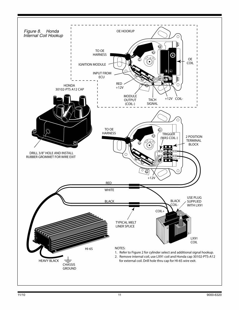
HONDA INTERNAL COIL CONVERSIONRefertoFig.8.Youwillrequireanexternalcoildistributorcap.
Removethedistributorcapanddustshield.Youshouldkeepthedustshieldforhighboostturboapplicationsasitreducesthepossibilityofarcing.Youmayhavetomodifyittofitthenewcap.CarefullynotetheOEwiringwithinthedistributor.RemovetheOEcoil(heldinplacewithtwoscrews).Installa2positionter-minalblockasshown.YoucanuseRadio-ShackP/N274-656.Tiewrap the terminalblock tooneof thecoilmountingholesorfabricateasupportbracketfromaluminumchannelmaterial.ConnecttheOEcoilwirestotheterminalblockasshown.
UsethehookupshowninFig.8tomakethepower,coil,andtriggerconnections.Then follow the instructionsstartingonpage3andreferbacktoFig.2tohookupthegroundwire,cylinderselect,andanyrequireddigitalinputandMAPsen-sorconnections.
Youwillhavetofabricateahighvoltagecableforusebetweenthecoilandnewdistributorcap.
FINAL CHECK Beforestartingtheengineforthefirsttime,doublecheckallelectrical connections. Make sure you have set the rotaryswitches for the intendedoperatingmode.Start theengineandverifythattimingissettomanufacturer’sspecifications.
TROUBLESHOOTING HI-6S OPERATION DidtheenginerunproperlybeforeinstallationoftheHI-6S?Ifnot,restoretheOEconnections,findandcorrecttheorigi-nalproblem.TheHI-6SwillnotfunctioniftheOEmoduleisdefective.DidtheHI-6Sfunctioncorrectlybeforetheproblemoccurred?Iftheanswerisyes,didyouchangeanythingthatmayhaveaffectedit?Ifyouconnectedanexternalcontrolorchanged ignitioncoils, trygoingback to the lastsetup thatworkedOKtohelpisolatetheproblem.
Iftheenginewillnotstart,orrunsroughorintermittently,fol-lowthecheckliststepsgiveninthefollowingsections.
NO STATUS LED WHEN IGNITION IS ON If thestatusLEDdoesn’t lightupaftertheignitionswitchisturnedon,checkpowerandgroundconnections.Useavoltmetertoverify+12voltsattheredHI-6SwireandtheCoil+terminal.Alsoverify+12voltswhentheignitionswitch is inthestartposition.Duringcranking,theHI-6Swillcontinuetooperatedowntoabout+5volts.
HOOKUP INSTRUCTIONS FOR SPECIFIC APPLICATIONS VEHICLES WITH HALL EFFECT SYSTEMS Many late model vehicles, especially European vehicles,haveOEHallEffectignitionsystems.UsethebasichookupshowninFig.2andexplainedstartingonpage3.TheHallEffectpickupcannotdirectlytriggertheHI-6S;theOEmodulemustbefunctioningcorrectlyandremaininstalled.
1972–86 MOPAR VEHICLES WITH 4 OR 5 PIN MODULES Use thebasichookupshown inFig.2andexplainedstart-ingonpage3.AlltheseMoparvehicleshaveaceramicbal-lastresistormountedonthefirewall.Fourpinmodulesuseatwoterminalballastresistor.Youcanbypassthisresistorbysolderingallthewiresgoingtoittogether.Fivepinmodulesuseafourterminalballastresistor.Theballastresistoralsosuppliespowertothefivepinmodule.Bypassingtheresis-tormaydamagethemodule.YoumustusethepowerrelaycircuitshowninFig.9ifyourvehiclehasafivepinmodule.
FORD VEHICLES WITH TFI-IV ELECTRONIC IGNITION Followtheinstructionsstartingonpage3andreferbacktoFig. 2 to hookup thegroundwire, cylinder select, andanyrequireddigitalinputandMAPsensorconnections.
FORD VEHICLES WITH DURASPARK ELECTRONIC IGNITION FordDuraspark applications require addition of an ignitionpower relayas theonlypracticalmeans tobypass theOEballastresistancewire.Usethepowerrelayhookupshownin Fig. 9 tomake the power, coil, and trigger connections.Thenfollowtheinstructionsstartingonpage3andreferbacktoFig.2tohookupthegroundwire,cylinderselect,andanyrequireddigitalinputandMAPsensorconnections.
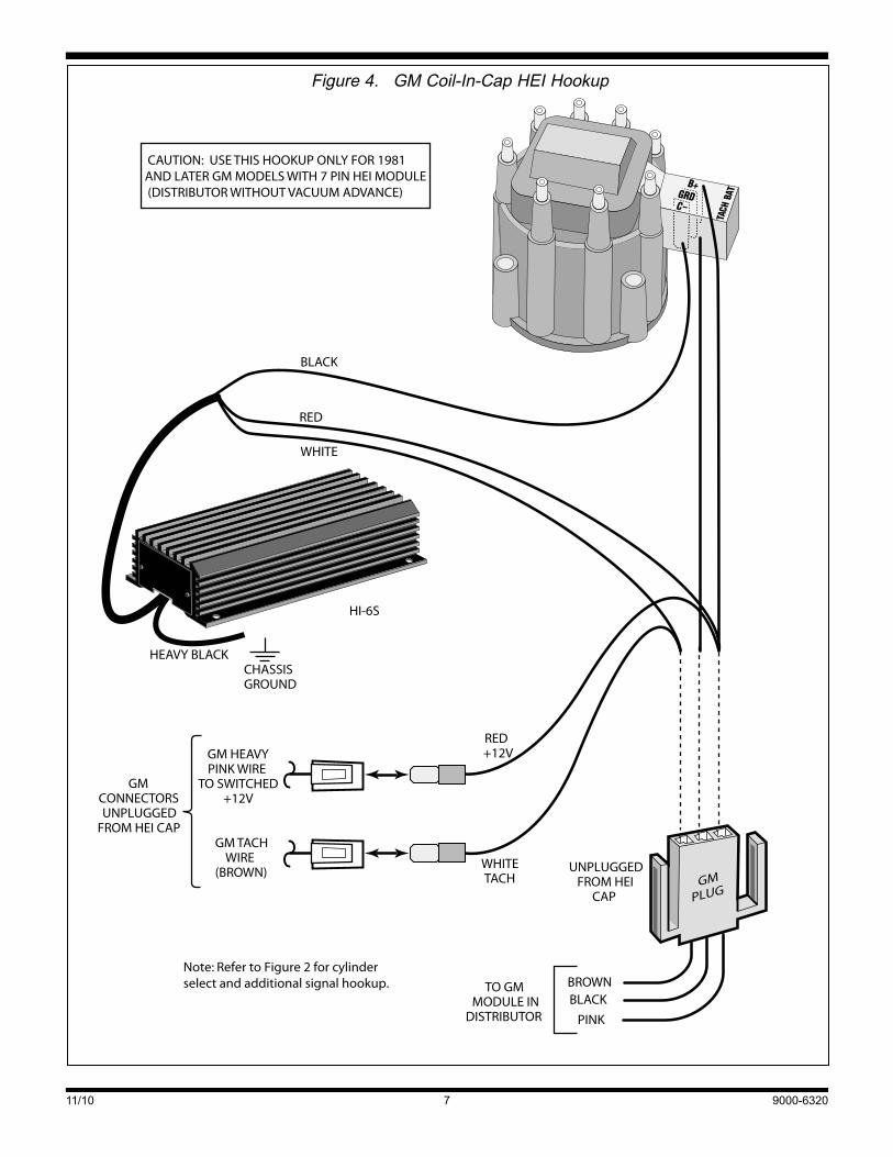
GM VEHICLES NotethattheHI-6ScannotbeusedwithearlyGMvehicleswith4or5pinHEImodules(typically1974-1980modelyearsanddistributorwithvacuumadvance).GMHEIsystemswithvacuumadvancerequiretriggeringdirectlyfromthemagneticpickup.UsetheCraneHI-6RCDsystem(P/N6000-6400)fortheseearlyGMHEIapplications.
Make thepower, coil, and triggerconnectionsasshown inFig.s4-6.Thenfollowtheinstructionsstartingonpage3andreferbacktoFig.2tohookupthegroundwire,cylinderselect,andany
HONDA AND ACURA INTEGRALatemodel Honda andAcura Integra have either a distribu-torwithinternalcoiloranexternalcoil.TheOEinternalcoilisnotsuitableforusewiththeHI-6SandmustbereplacedwithaCraneLX91orPS91.Internalcoildistributorscaneasilybeconvertedtoexternalcoilbychangingthedistributorcap.
Detailedinstructionsaregiveninthefollowingsections.

11/10 9000-63206
ENGINE WILL NOT START 1. If the status LED lights upwhen the ignition switch is
turnedonbuttheenginewillnotstart,verifythatthesta-tusLEDblinkswhiletheengineiscranking.
2. IfthestatusLEDdoesn’tblink,theHI-6Sisnotreceivingatriggersignal.Rechecktriggersignalelectricalconnec-tions(whitewire)andtriggersource.
3. IfthestatusLEDblinks,butenginewillnotstart,recheckcoil primary connections or replace coil.TheonlywiregoingtoCoil-shouldbetheblackHI-6Swire.Tachandfuel injection systemsmust be connected to thewhiteHI-6Striggerwire.Ifthehookupiscorrectandtheenginewill not start upon installation of anHI-6S system, thefuelinjectionmaynotbereceivingapropertriggersignal.PleasecallCraneTechSupportforfurtherassistance.
CHECKING FOR SPARKTocranktheenginewithoutstartingortocheckforspark,useaKDToolstestplug.Makeupalengthofsparkplugwiretoconnectthetestplugtothecoil.
MISFIRE OR INTERMITTENT OPERATION 1. MisfireathighRPMmaybecausedbylowvoltageatthe
Coil+terminalduetopoorwiringorballastresistance.IfthevoltageattheCoil+terminaldropsbelow+11Vwhentheengineisrunning,youshouldaddanignitionpowerrelayusingthehookupshowninFig.9.
2. Aweakbatterymaycausemisfireorintermittentopera-tion,especiallyathighRPM.Ifindoubt,chargeorreplacethebattery.
3. FieldexperiencehasshownthatmisfireathighRPMisusu-allynotanelectricalproblemwithintheHI-6S.Coilfailureandarcingatcoilorplugconnectionsarecommoncauses.
4. Routeall triggersignalconnectionsawayfromanycoilconnectionsandsparkplugwires.
5. Replace spark plugs, plug wires, distributor cap, androtor.Useonlyspiralcoreplugwires.Verifypluggapandheatrange.Checkforlooseorcorrodedconnections.
RUNNING ON Runningonisaconditionwheretheenginecontinuestorunaftertheignitionswitchisturnedoff.First,verifythatthecon-ditionisduetotheignitionsystem.Dieselingcancauserun-ningon.Theenginewillrunveryroughwhenitisdieseling.Thismaybeduetoanoverlyrichmixture,excessivetiming,orheavycarbondeposits.Dieselingcanusuallybecuredbyinstallingcoldersparkplugs.
With ignition runon, theenginecontinues to runsmoothly,as if the ignitionhadnotbeenturnedoff.RunonproblemscanoccurwhenusingtheignitionpowerrelaycircuitshowninFig.9.Currentleaksthroughthechargingsystemindicatorlightandkeeps the relayenergizedevenwhen the ignitionswitchisturnedoff.Tosolvethisproblem,installthesupplieddiodeonthevoltageregulator.
RED / LIGHT GREEN
DARK GREEN / YELLOW MELT LINER SPLICE
HI-6S
HEAVY BLACKCHASSISGROUND
TO FORDOE HARNESS
A
RED WHITE
BLACK
FORDOE
COIL
Note: Refer to Figure 2 for cylinderselect and additional signal hookup.
Figure 3. Ford TFI-IV Hookup
11/10 9000-63207
BROWNBLACK
TO GMMODULE IN
DISTRIBUTOR PINK
GM HEAVYPINK WIRE
TO SWITCHED+12V
GM TACHWIRE
(BROWN)
RED+12V
WHITETACH
GMCONNECTORSUNPLUGGED
FROM HEI CAP
HI-6S
HEAVY BLACK
BLACK
RED
WHITE
CHASSISGROUND
CAUTION: USE THIS HOOKUP ONLY FOR 1981AND LATER GM MODELS WITH 7 PIN HEI MODULE(DISTRIBUTOR WITHOUT VACUUM ADVANCE)
GMPLUG
UNPLUGGEDFROM HEI
CAP
Note: Refer to Figure 2 for cylinderselect and additional signal hookup.
Figure 4. GM Coil-In-Cap HEI Hookup

11/10 9000-63208
Conductednoisefromthecoilprimaryiscarriedthrough+12voltpowerconnections.ConductednoiseappearsasawhinethatfollowsengineRPMandmayaffectallsystemsincludingtapeplayersandFMradio.
UsethefollowingchecklisttoreduceRFnoise:
1. Makesureagroundstrapisinstalledbetweentheengineandchassis.Makesurethatthecoilbracketisgrounded.
2. Makesurethatradio,tapeandCBsystemsaregroundeddirecttothechassis.
3. Mount theHI-6Sunitas farawayaspossible fromtheantenna(includingwindshieldantenna)andotherelec-tronicdevices.MakesuretheHI-6S isgroundeddirecttothechassis.Keepthegroundwireshort,preferablynomorethan6”.
4. Replacesparkplugwireswithspiralcoretypewire.Replacerotorandcap.Applyasmallamountofsiliconedielectricgreasetotherotortipandtoallhighvoltageterminals.Useonlyresistorsparkplugswhenrunningonthestreet.
HI-6S
HEAVY BLACKCHASSISGROUND
COIL +
BLACKCOIL -
GRAY
RED
WHITE
CONNECTOR
BLACKCONNECTOR
GMOE HARNESSUNPLUGGEDFROM COIL
GM OECOIL
Note: Refer to Figure 2 for cylinderselect and additional signal hookup.
Figure 5. GM Dual Plug Coil Hookup
GMvehicleswithDelcotronalternatorandinternalregulator:refertoFig.10.Installthediodeinthethinbrownwiregoingtotheindicatorlight.
GMorFordwithexternalvoltageregulator:refertoFig.11.ForGMvehicles,installthediodeonthe#4terminal
Installationofthediodemaynotcorrecttherunonproblemonsomevehicles.RefertoFig.12.Usea1973-76Chryslerdualballastresistor(availableatmostpartsstores).Solderajumperwireacrossbothterminalsononeend.Thenconnectthetermi-nalsontheotherendtogroundandtotheignitionswitchwire.Theballastresistorsendstheleakagecurrenttoground.
RADIO NOISE All ignitionsystemsgeneratesomenoise.Apowerfulmulti-spark ignitionsystemsuchas theHI-6Swill tend togener-atemorenoisethantheOEignition.Tosomeextentthisisunavoidable,butstepscanbetakentoreducethenoiselevel.
Radio frequency(RF)noise is radiated fromcoilandsparkplug wires. RF noise primarily affectsAM and CB radios.

11/10 9000-63209
OPERATION TheTRC-2moduleallowsyoutoadjust theamountofretardproducedbytheHI-6S.ItalsocontainsanLEDthatindicateswhentheretardfunctionisactivated.HowyouusetheTRC-2depends on whether you have connected it for continuous,demand,orboost-proportionalretard.
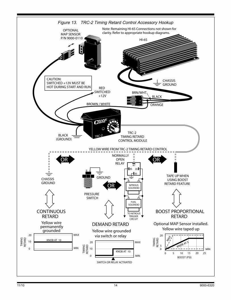
CONTINUOUS RETARD RefertoFig.13.ConnecttheyellowwirefromtheTRC-2directlytochassisgroundforcontinuousretard.Sincetheretardfeatureisactiveallthetime,theLEDontheTRC-2willbeilluminatedwheneverthekeyison.Turningtheknobfullycounterclockwise(0°)producesnoretard.Turningtheknobclockwiseincreasestheretardupto20°.TheTRC-2isapproximatelylinearthrough-out itsrange,sohalfscaleisabout10°ofretard.Forpreciseretardcalibration,youmustuseahigh-qualitytiminglight.
Theusesforthistypeoftimingcontrolincludeadjustingtim-ingtopreventknockbecauseofinferiorfuelqualityorinsuf-ficient octane, altitude adjustments, etc.As you drive, youcanapplyjusttheamountofretardrequiredtopreventsparkknockandoptimizefueleconomy.Inracingapplicationstheretardcontrolcanbeusedtotunethevehicletospecifictrackandatmosphericconditions.TheTRC-2alsomaybeusedonvehicleswithmechanicaladvancedistributororcomputerenginecontrolstochangethetotalignitiontiming.
DEMAND RETARD RefertoFig.13.ConnecttheyellowwirefromtheTRC-2toanormallyopenswitchorrelaythatwillcompleteapathtochassisgroundwhenretardisdesired.Example:Apressureswitch thatclosesatacertainboost level.TheLEDontheTRC-2willlightupwhentheyellowwireisgrounded.When
Conductednoisecanbereducedbyinstallingapowerlinenoisefilter(availableatRadioShack)neartheaffectedradio.
TRC-2 TIMING RETARD CONTROL ACCESSORY TheCraneCamsTRC-2isanaccessoryforHI-6Ssystemsthat provides driver-adjustable retard.TheTRC-2 can pro-videcontinuoustimingretard(0°–20°),retardusingaswitch(0°–20°),orretardproportionaltoboost(upto4°perpsi)onsuperchargeror turbocharger installations (withanoptionalMAPsensor,notincluded).
INSTALLATION Complete the installationof theHI-6S ignitionmoduleprior toinstalling theTRC-2. Fig. 13 shows hookup of theTRC-2 totheHI-6S.TheredwirefromtheTRC-2isconnectedtoakeyswitched,+12voltsupply.YoumayspliceitintotheredwireontheHI-6Sadapterharness.TheyellowwirefromtheTRCiscon-necteddirectlytogroundforcontinuousretardcontrol,throughaboost/nitrousswitchtogroundforretardondemand,ortapedoffwhenusingtheoptionalboostsensor.Whenusingretardondemand,theswitchmustcompletethecircuittogroundtoacti-vatetheretard(useanormallyopenswitchorrelay).
FINAL CHECK Beforestartingtheengineforthefirsttime,doublecheckallelectricalconnections.SettheTRC-2knobto0°(fullycoun-terclockwise), then start the engine and check the ignitiontiming.Thetimingmaychangeafewdegreesafterinstalla-tion.Resettimingtomanufacturer’sspecs.Uponstartingtheengine, theLEDontheTRC-2modulewillbe litonly if theyellowwireisgrounded.
HI-6S
HEAVY BLACK
RED
WHITE
BLACK
CHASSISGROUND
GM OEHARNESS
UNPLUGGEDFROM COIL
GM OECOIL
COIL+
COIL-
Note: Refer to Figure 2 for cylinderselect and additional signal hookup.
Figure 6. GM LT-1 Hookup

11/10 9000-632010
MODULEOUTPUT
BLUE
NOTES:1. Refer to Figure 2 for cylinder select and additional signal hookup.2. Cut wires at Honda coil plugs and connect wire harness to HI-6 as shown.3. Use LX91 coil in place of Honda coil.
HI-6
HEAVY BLACK CHASSISGROUND
– +
12 VOLTBATTERY
+12V
GROUND
HEAVY REDBAT +
LX91COIL
COIL +
COIL +
BLACKCOIL - USE PLUG
SUPPLIEDWITH LX91
TYPICAL MELTLINER SPLICE
FM
BLK-YEL
TACHBLUE
TO OEIGNITIONSWITCH
ANDTACH
TYPICAL1/4" MALE-FEMALE
QUICKDISCONNNECTS
WHITETRIGGER
TO OEIGNITIONMODULE
SWITCHED
+12VBLK-YELMODULEOUTPUT
BLUE
LENGTH OFWHITE WIRE
LENGTHOF RED
WIRE
TOP VIEW OF HONDA COIL(shown for reference only)
SMALLPLUG
LARGEPLUG
SWITCHED+12V
FM
F M
FM
THIN REDSWITCHED
+12V
OROR
OR
TO OEIGNITIONSWITCH
ANDMODULE
FOUR TERMINALCOIL HOOKUP
THREE TERMINALCOIL HOOKUP
F M
SWITCHED +12VBLACK/YELLOW
MODULE +12VBLACK/YELLOW
123
TOP VIEW OF HONDA COIL(SHOWN FOR REFERENCE ONLY)
123 COILPLUG
WHITETRIGGER
THIN RED
REDWHITE
SWITCHED +12V
FM
Figure 7. Honda External Coil Hookup
11/10 9000-632011
HI-6S
HEAVY BLACKCHASSISGROUND
RED
WHITE
BLACK
NOTES:1. Refer to Figure 2 for cylinder select and additional signal hookup.2. Remove internal coil, use LX91 coil and Honda cap 30102-PTS-A12 for external coil. Drill hole thru cap for HI-6S wire exit.
TO OEHARNESS
TO OEHARNESS
TRIGGER(WAS COIL-) 2 POSITION
TERMINALBLOCK
+12V
+12V
RED+12V
TACHSIGNAL
MODULEOUTPUT(COIL-)
INPUT FROMECU
IGNITION MODULE
OE HOOKUP
OECOIL
+ -
DRILL 3/8" HOLE AND INSTALLRUBBER GROMMET FOR WIRE EXIT
HONDA30102-PTS A12 CAP
LX91COIL
TYPICAL MELTLINER SPLICE
COIL+
BLACKCOIL-
USE PLUGSUPPLIEDWITH LX91
COIL-
Figure 8. HondaInternal Coil Hookup

11/10 9000-632012
HI-6S
+
12 VOLTBATTERY
IGNITIONSWITCH
BALLASTRESISTOR
+12V
RUN
START
CUT WIREAND REMOVECONDENSER
IF NECESSARY TACHOMETER
RPMX100
GROUND
CONDENSER
HEAVY BLACKCHASSISGROUND
GROUND
O. E.ELECTRONIC
IGNITIONMODULE
87
8630
85OE WIRE THAT
WENT TO COIL+
OECOIL
CAUTION: WHEN USING THE RELAY CIRCUIT SHOWN,YOU MUST ALSO ADD A DIODE BETWEEN THEVOLTAGE REGULATOR AND CHARGING INDICATORLAMP AS SHOWN IN FIGURE 10 TO PREVENT RUN ON.
USE HEAVY GAUGE16 AWG STRANDED WIRE
FOR OPTIMUM RESULTS-REPLACE WITH CRANE LX91 COILNOTES:
1. Use relay as shown to supply direct +12V power to HI-6S and coil.2. Refer to Figure 2 for cylinder select and additional signal hookup.3. Use 1/4" female quick disconnects for relay connections.
IGNITION POWER RELAYSUCH AS RADIO-SHACK
275-226
CUT OE WIRESTO COIL ANDRECONNECTAS SHOWN
TYPICAL MELTLINER SPLICE
USED TO CONNECTTO OE HARNESS
BLACK
RED
WHITE
Figure 9. Ignition Power Relay Hookup

11/10 9000-632013
theLED is lit, the retard feature is active and the spark isretardedbytheamountsetontheTRC-2knobfrom0°–20°.TheTRC-2 isapproximately linear throughout its range,sohalfscaleisabut10°ofretard.Forpreciseretardcalibration,youmustuseahigh-qualitytiminglight.ThediagraminFig.13showsanexamplewiththeknobsetfor10°ofretard.
Thistypeoftimingcontrolisgreatfornitrousoxideandsuper-charged applications, or any vehicle that requires adjustableretard.Fornitrousapplications,Fig.13showshowanormallyopenrelayisusedtogroundtheyellowwirewhennitrousandfuelsolenoidsareactivated.Thepinnumbersareforastan-dardautomotiverelaysuchasRadioShackP/N275-226.Fig.13alsoshowsapressureactivatedswitchdesignedtoretardtimingwhentheboostpressurereachesapre-setvalue.NAPABalkamp offers two adjustable pressure switches: P/N 701-1591(3-7psigrange)andP/N701-1603(1.1-3psigrange).
Demandretardmodeisalsogreatforcrank-triggersystemswhereamomentarystartretardisrequired.Amanualswitchoranormallyopenrelayenergizedbythestartersolenoidcanbeusedtogroundthe yellowwire during cranking to provideup to 20° of startingretard.Oncetheswitchisreleased,timingreturnstonormal.
BOOST PROPORTIONAL RETARD RefertoFig.13.AnoptionalMAPsensor(CraneP/N9000-0110) is required for boost proportional retard. This sen-sor is a rugged unit that canmeasure pressures up to 15psiabovenormalatmosphericpressure.Thesensorcomeswithvacuumtubingandadaptersforplumbingittotheintakemanifold.TheyellowwirefromtheTRC-2shouldbetapedupwhenusingtheMAPsensor.
WhentheMAPsensorisconnected,theretardsettingontheTRC-2nowreferstoaretardslopefrom0°to4°perpsiofboost.Simplydividetheknobsettingby5todeterminetheretardslope(seeFig.13below).Forexample,iftheknobissetto5°theretardslopeis1°perpsiandat5psiofboosttheretard is5°.Asboostrisesfurther, theretard increasesatthissameslopeuptoamaximumof20°.Iftheboostlevelexceeds15psi,theretardlevelsoffasshowninFig.13below(sensordamagemayoccurabove18psi).
ThestatusLEDontheTRC-2illuminateswhenretardisbeingapplied.Undermostconditions,thisoccursbetween0.5and1.0psiofboost.Asboostrises,retardriseswithaslopedeterminedbytheknobsetting.Notethattheretardslopestopsrisingwhentheboostreaches15psiortheretardreaches20°.TheTRC-2isapproximatelylinearthroughoutitsrange,butforpreciseretardcalibrationuseatiminglighttoobtainretardvalue.
TROUBLESHOOTING DidtheenginerunproperlybeforeinstallationoftheTRC-2?Ifnot,removetheboththeTRC-2andHI-6Sunits,reinstalltheOEignitionoranotherknowngoodunitandthenfindandcorrecttheoriginalproblem.MakesuretheHI-6Ssystemfunctionsprop-erlybefore installingor troubleshooting theTRC-2accessory.DidtheTRC-2functioncorrectlybeforetheproblemoccurred?If theanswer isyes,didyouchangeanything thatmayhaveaffectedit?Ifyouconnectedanexternalcontrolorchangedigni-tioncoils, trygoingbacktothelastsetupthatworkedtohelpisolatetheproblem.RefertotheHI-6Sinstallationinstructions
No. 2TERMINAL
BATTERMINAL
1973-83 GMDELCOTRON
No. 1TERMINAL
NOTE:USE BUTT SPLICES TO CONNECT DIODE, THEN WRAP WITH ELECTRICAL TAPE.
BROWN WIRETo No. 1 TERMINAL
INDICATORLAMP
1N4007 DIODE
TYPICAL BUTTSPLICE
Figure 10. Diode Installation on Delcotron Alternator
NOTE:USE BUTT SPLICES TO CONNECT DIODE, THEN WRAP WITH ELECTRICAL TAPE.
FORD VEHICLESATTACH DIODE TOTERMINAL MARKED "I"
EARLY GM VEHICLESATTACH DIODE TO TERMINAL MARKED "4"
1N4007 DIODE
INDICATORLAMP
VOLTAGEREGULATOR
TYPICAL BUTTSPLICE
Figure 11. Diode Installation on External Regulator
CHASSISGROUND
87
8630
85
JUMPERWIRE
IGNITIONSWITCH
CHRYSLER DUALBALLAST RESISTOR
CHASSISGROUND
TO BATTERY+
IGNITION POWER RELAYRADIO SHACK 275-226
+12V POWERTO COIL +AND HI-6S
Figure 12. Run-On Fix Using Chrysler Ballast Resistor
formoredetails,includingtheuseoftheHI-6Sbuilt-indiagnosticLEDlocatedontheignitionmodule.
Ifyouarenotgettingtheamountofretardyouexpect,checktheLEDontheTRC-2module;itlightsupwhenretardisbeingapplied.If itdoesnot lightupincontinuousordemandretardmodes,checktheyellowwirefromtheTRC-2.Itmustcontactagoodchassisgroundwhenretardisneeded.Alsore-checkthebrown/whitewireconnectionfromtheTRC-2totheHI-6S.
Inboost retardmode theamountof retardshouldbepropor-tional to thepressuremeasuredby theoptionalMAPsensor.Theamountof retardmayvary inagivenapplication if localatmospheric (barometric) pressure changes significantly.Thisoccursmostoftenwithachangeinaltitudeof1000feetormore.
IftheTRC-2settingsseemtobeoff,checkthetraveloftheknobfromno-retard(0°)tomaximum(20°).Makesurethatthepointerisproperlyalignedwhentheknobisateachlimit.
11/10 9000-632014
HI-6S
CHASSISGROUND
REDSWITCHED
+12V
NITROUSSOLENOID
FUELSOLENOID
TO NITROUSTRIGGERCIRCUIT
8786
30
85
BOOST (PSI)
20
50
0 5 10 15 20 25MINMIN
MAX
MAX
KNOB AT 5
TIM
ING
RETA
RD
TIM
ING
RETA
RD TIM
ING
RETA
RD
20
10
0
KNOB AT 10
MIN
MAX
SWITCH OR RELAY ACTIVATED
20
10
0
KNOB AT 10
PRESSURESWITCH
NORMALLYOPENRELAY
CHASSISGROUND
GROUND
RETARD
TRC-2
OR OR
OR
TRC-2TIMING RETARD
CONTROL MODULE
TAPE UP WHENUSING BOOST
RETARD FEATURE
YELLOW WIRE FROM TRC-2 TIMING RETARD CONTROL
BLACK(GROUND)
BROWN / WHITE
CONTINUOUSRETARD
DEMAND RETARD
BOOST PROPORTIONALRETARD
Yellow wirepermanently
grounded Yellow wire groundedvia switch or relay
Optional MAP Sensor installed.Yellow wire taped up
A
BC
BLACK
ORANGE
BRN/WHT
Note: Remaining HI-6S Connections not shown forclarity. Refer to appropriate hookup diagrams.
CAUTION:SWITCHED +12V MUST BEHOT DURING START AND RUN
OPTIONALMAP SENSORP/N 9000-0110
Figure 13. TRC-2 Timing Retard Control Accessory Hookup