hi - hose century installation · pdf filemarch 2003 séries no 921193 rev.c...
TRANSCRIPT
HI - HOSE CENTURY
SUCTION PUMPS AND
REMOTE DISPENSERS
3/G3000
INS
TA
LL
AT
ION
OP
ER
AT
ION
March 2003 Séries No 921193 Rev.C
INSTALLATION & OPERATION
HI - HOSE CENTURY SUCTION PUMPS
AND REMOTE DISPENSERS
3/G3000.

Séries No 921193 Rev.C March 2003
Module “INSTALLATION & OPERATION”
Intelligent Global Electronics Module
Dresser Europe GmbH
Wayne Germany Dresser Inc.
All rights reserved.
Printed in Europe
No part of this publication may be electronically or mechanically reproduced, stored in a retrieval system, or transmitted, in any form or by any means without express written permission of Dresser Inc. Translation of this material to another language without express written permission of Dresser Inc. is prohibited.
The information in this publication is for informational use only and is subject to change without notice. The contents should not be construed as a commitment by Dresser Inc. who assumes no responsibility or liability for inaccuracies that may appear in this publication.
Séries No 921193 Rev.C March 2003 1
WARNING
READ THIS MANUAL BEFORE YOU BEGIN Dispensers have both electricity and hazardous, flammable and potentially explosive liquid. Failure to follow the below precautions and the Warning and Caution instructions in this manual may result in serious injury. Follow all rules, codes and laws that apply to your area and installation.
SAFTY PRECAUTIONS- INSTALLATION AND MAINTENANCE Always make sure ALL power (motors and electronic head) to the dispenser is turned OFF before you open the dispenser cabinet for maintenance. Physically lock, restrict access to, or tag the circuit breakers you turn off when serving the dispenser. Be sure to trip (close) the emergency valve(s) under the dispenser BEFORE beginning maintenance. Make sure that you know how to turn OFF power to the dispenser and submersible pumps in an emergency. Have all leaks or defects repaired immediately.
EQUIPMENT PRECAUTIONS Be sure to bleed air from product lines of remote dispensers and prime suction pumps before dispensing product, otherwise, damage to the equipment may occur. Always use the approved method for lifting the dispenser. Never lift by the nozzle boot, sheet metal, valance, etc., otherwise equipment damage or personal injury may occur.
USE ONLY GENUINE PARTS. For product liability to be valid no changes, completions or similar may be done in the equipment without the written consent of Wayne.
HOW TO CONTACT WAYNE Trouble with the installation and operation of the dispenser should be referred to your Wayne service personnel or Wayne Technical Support.
INDICATORS AND NOTATIONS
DANGER
Danger indicates a hazard or unsafe practice which, if not avoided, will result in severe injury or possible death.
WARNING
Warning indicates a hazard or unsafe practice which, if not avoided, may result in severe injury or possible death.
CAUTION
Caution indicates a hazard or unsafe practice which, if not avoided, may result in minor injury.
Note:
Important information to consider, otherwise, improper installation and/or damage to components may occur.

Séries No 921193 Rev.C March 2003 2

Séries No 921193 Rev.C March 2003 3
TABLE OF CONTENTS
1 INTRODUCTION.......................................................................................................... 8 1.1 Dispensers Covered......................................................................................................................8 1.2 Model Description .........................................................................................................................8 1.3 Model Designation Format ...........................................................................................................9 1.4 Technical information .................................................................................................................10 1.5 Safety Precautions ......................................................................................................................11 1.6 Local, State and Federal Codes.................................................................................................11 1.7 Inspect The Equipment...............................................................................................................11
2 GAS STATION PREPARATION ................................................................................ 12 2.1 Emergency Shutdown.................................................................................................................12 2.2 Safety switch................................................................................................................................12 2.3 Emergency shut-off valve...........................................................................................................13 2.4 Pipelines (Remote Pumps) (For UL markets) ...........................................................................13 2.5 Check Valves (Suction Pumps Only) (For UL markets) ..........................................................15 2.6 Connecting More Than One Pump To a Tank (Suction Dispensers) (For UL markets) .......15 2.7 Fill Pipe (For UL markets)...........................................................................................................15 2.8 Venting (For UL markets) ...........................................................................................................16
3 INSTALLING THE DISPENSER................................................................................ 17 3.1 Cable drawing..............................................................................................................................20
3.1.1 Routing of power cables......................................................................................................20 3.2 Emergency shutdown.................................................................................................................20 3.3 Safety switch................................................................................................................................21 3.4 Submersible Pump Controls ......................................................................................................21 3.5 Multiple Dispenser Wiring ..........................................................................................................22 3.6 Hose Installation (UL) .................................................................................................................22 3.7 Bleeding Product Lines (Remote Dispenser) ...........................................................................23 3.8 Priming Suction Pumps..............................................................................................................23 3.9 Above Ground Storage Tanks....................................................................................................25
4 START-UP PROCEDURE ......................................................................................... 26 4.1 Hose Position Coding .................................................................................................................26 4.2 Nozzle Switch Check...................................................................................................................27 4.3 Meter Check .................................................................................................................................28
4.3.1 Pumps Calibration...............................................................................................................28 4.4 Link Belt Adjustment ..................................................................................................................29
4.4.1 Z-profile belt ........................................................................................................................29 4.5 Adjusting Compact Pumping Unit .............................................................................................29 4.6 Fluorescent Lights ......................................................................................................................30 4.7 Totalizer Readings ......................................................................................................................30
4.7.1 Electro-mechanical volume totalizer (Option) .....................................................................30 4.7.2 Volume Totalizer Through Preset .......................................................................................30
4.8 Coalescent Filter Pump – Start Up Procedure .........................................................................31 4.9 Press Filter Pump – Start Up Procedure...................................................................................31

Séries No 921193 Rev.C March 2003 4
5 COMPUTER OPERATION.........................................................................................33
5.1 Introduction ................................................................................................................................. 33 5.2 Programming functions ............................................................................................................. 33 5.3 Access to functions.................................................................................................................... 33 5.4 Exit (F00) ...................................................................................................................................... 35 5.5 Password Change (F33) ............................................................................................................. 36 5.6 Filling Modes (F01) ..................................................................................................................... 36 5.7 Checking the Electronics Totals (F11)...................................................................................... 36
5.7.1 Access to the statistic model .............................................................................................. 38 5.7.2 Mode “Statistics” ................................................................................................................. 39
5.8 Changing Unit price (F03) .......................................................................................................... 40 5.8.1 Changing prices on Side A ................................................................................................. 40 5.8.2 Changing prices on Side B ................................................................................................. 43
5.9 Pump Startup .............................................................................................................................. 45 5.9.1 Changing decimal points of unit price ................................................................................ 45 5.9.2 Changing decimal points of Paying Total ........................................................................... 47 5.9.3 Changing decimal points of Volume................................................................................... 48
6 DEMOUNTING ...........................................................................................................50 6.1 Preparations ................................................................................................................................ 50 6.2 Drain fuel from the pump ........................................................................................................... 50
7 OPERATION ..............................................................................................................51 7.1 Introduction ................................................................................................................................. 51 7.2 Portable Tanks and Containers................................................................................................. 51 7.3 Operation of the Preset (Option) ............................................................................................... 51
7.3.1 Twelve button keyboard ..................................................................................................... 52 7.3.2 Five button keyboard .......................................................................................................... 53
7.4 Health Note .................................................................................................................................. 54 7.5 Hazardous Zone Areas............................................................................................................... 54
7.5.1 Hazardous Zone UL ........................................................................................................... 55 7.5.2 Hazardous Zone IEC .......................................................................................................... 56
7.6 How To Get Service On Your Dispenser .................................................................................. 57 8 PREVENTIVE MAINTENANCE .................................................................................58
8.1 Water Damage ............................................................................................................................. 58 8.2 Maintenance Guidelines............................................................................................................. 58 8.3 Cleaning of filters........................................................................................................................ 58
8.3.1 Inlet filter (Standard) ........................................................................................................... 59 8.3.2 Inlet filter (US)..................................................................................................................... 59 8.3.3 After filter cleaning: ............................................................................................................. 60 8.3.4 Coalescent Filter................................................................................................................. 60 8.3.5 Press Filter.......................................................................................................................... 60
9 ENGINEERING DRAWINGS......................................................................................61 9.1 Installation Instructions 3/G3000 .............................................................................................. 62 9.2 Electrical Installation Scheme 3/G3000P.................................................................................. 65 9.3 Electrical Installation Scheme 3/G3000D ................................................................................. 66 9.4 Installation Instruction of Models 3/G3397P/FC-FP ................................................................ 67 9.5 Installation Instruction of Suction Models ............................................................................... 68 9.6 Installation Instruction of Remote Models ............................................................................... 69 9.7 7151-C – Typical Electric Installation Scheme......................................................................... 70
Séries No 921193 Rev.C March 2003 5
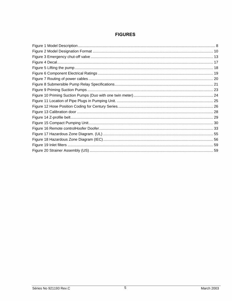
FIGURES Figure 1 Model Description ................................................................................................................................... 8
Figure 2 Model Designation Format ................................................................................................................... 10
Figure 3 Emergency chut-off valve ..................................................................................................................... 13
Figure 4 Decal..................................................................................................................................................... 17
Figure 5 Lifting the pump .................................................................................................................................... 18
Figure 6 Component Electrical Ratings .............................................................................................................. 19
Figure 7 Routing of power cables ....................................................................................................................... 20
Figure 8 Submersible Pump Relay Specifications.............................................................................................. 21
Figure 9 Priming Suction Pumps ........................................................................................................................ 23
Figure 10 Priming Suction Pumps (Duo with one twin meter) ............................................................................ 24
Figure 11 Location of Pipe Plugs in Pumping Unit. ............................................................................................ 25
Figure 12 Hose Position Coding for Century Series........................................................................................... 26
Figure 13 Calibration door .................................................................................................................................. 28
Figure 14 Z-profile belt........................................................................................................................................ 29
Figure 15 Compact Pumping Unit....................................................................................................................... 30
Figure 16 Remote controlHoofer Doofer............................................................................................................. 33
Figure 17 Hazardous Zone Diagram. (UL) ......................................................................................................... 55
Figure 18 Hazardous Zone Diagram (IEC)......................................................................................................... 56
Figure 19 Inlet filters ........................................................................................................................................... 59
Figure 20 Strainer Assembly (US) ...................................................................................................................... 59

Séries No 921193 Rev.C March 2003 6
HEALTH AND SAFETY REGULATIONS When using inflammable liquids it is important that the following rules and regulations are followed:
Within a radius from the pump it is prohibited to smoke and light or enter fire. Idle running is prohibited while fuelling. Distribution box must be easily accessible and may not be blocked with goods or similar. Always let specialists make electrical installations of all kinds. Special regulations are applied! WARNING!
Never run a leaking pump! (Failure to observe this information results in immediate danger to life.) Please watch any leakage from pumps. If there is a leakage, cut the power to the pump (motors and electronic head) and call Wayne After Sales Service. Always follow the regulations regarding handling of petrol and oil, published by each oil company. Always follow the special authority demands regarding the vapour recovery system. Make sure that adequate functioning fire-extinguisher is in its place and not blocked. WARNING!
ge which may result in electric shock or fire, disconnect the main power (motors and electronic head) prior to any work WARNING!
Action to be taken after elimination of short-circuits in components located behind the motor protection: contactors and protective motor switches must be replaced. To avoid incorrect function or that the pump is damaged, make sure that there is enough fuel in each tank. Adequate personal safety equipment should be used by maintenance of the equipment (gloves, breathing mask, glasses etc.).
Explosion hazard Prohibited to smoke Prohibited to take fire

Séries No 921193 Rev.C March 2003 7
Product liability
For product liability to be valid no changes, completions or similar may be done in the equipment without the written consent of Wayne. Intended use
The pump is designed to move (pump) petrol, kerosene and diesel in correct quantities from tank to vehicle. Product limitation The pump is designed and approved for measuring of petrol, kerosene and diesel, all in accordance with type approval.

Séries No 921193P Rev.C March 2003 8
1 INTRODUCTION
1.1 Dispensers Covered This manual describes the installation and operation of Hi - Hose Century dispensers. Hi - Hose Century dispensers are designated by 3/G3000 model number series. These dispensers have iGEM computer and either Lift-to-Start or Auto on nozzle boot configurations.
The 3/G3000 dispenser may be installed and operated as a stand-alone unit or as a component part of a Wayne Management Control System. This manual provides installation and operation information for 3/G3000 series dispensers operating as stand-alone units; however, information concerning Wayne Control Systems is included where appropriate. Each side of the dispenser is referred to as a fuelling point for connection to a control system. Single-sided dispensers are designated by an "R" in the model number suffix and have only one fuelling point. Complete installation and operation information for the appropriate Wayne Control System can be obtained from the manuals provided with the system.
For programming the iGEM computer on these models, refer to the Programming Manual, Part Number 921279.
A description of each model is shown in Figure 1 and the model number suffix designations are defined in Figure 2.
1.2 Model Description
Configurations for Global “H”Style & Dispensers
Figure 1 Model Description
3/G3390 3/G3490 3/G3498
3/G3399 3/G3389 3/G3388
3/G3387 3/G3397 PFC3/G3397 PFP –
3/G3490
3/G3390
3/G3498
3/G3389
3/G3388
3/G3397 PFP 3/G3397 PFC
3/G3399
Single ProductPump and DispenserTwo Hose
Two ProductsPumps and DispensersTwo Hose
Six Hose
Four Hose
Multi-GradePumps and Dispensers
Eight Hose
Four Hose Four Hose

Séries No 921193 Rev.C March 2003 9
1.3 Model Designation Format
Prefix / Main Body / First Suffix / Second Suffix X X X / A B C D E F / Z Z Z Z Z Z Z Z / Y Y Y Y Y Y Y Y
Prefix Electronic & Hydraulic Configuration
3 iGEM + iGHM X
Main Body
Model Series G Global A 3 Hi-Hose Century B Model Style 3 1,2 or 3 products pump or dispenser 4 4 products pump or dispenser
C
Construction 8 Narrow body 9 Wide body
D
Nozzle & Product
Configuration 7 Twin (Duo I), Lane Oriented
8 Duo (Duo II), Lane Oriented 9 Quadro, Lane Oriented 0 MGD, 3 or 4 products
E
Hydraulic System D Dispenser - Remote P Pump - Self Contained
F
Activation Default - Lift -to-Start A Auto On (not UL Listable) - Magnetic Activation
on Nozzle A1 Auto On (not UL Listable) - Magnetic Activation
on Flipper B Flow Indicator D 3 Phase Operation E Alcohol Densimeter (Brazil only) G Filter (Remotes only) J Explosion Proof J-Box O No EMT's - Electronic Totals Only - Default
One (1) EMT per Product Stop Button P Stop Button - Electrical Interruption P1 Stop Button - Computer Controlled Function Preset S Preset - 16 button with dedicated display -
reserved S1 Preset - 12 Button - Shared functions with
sales display S2 Preset - 5 Button - Shared functions with sales
display
Z

Séries No 921193 Rev.C March 2003 10
2nd Suffix Options 3 Quadro Dispenser LCD U. Price per each
Product - Default Sales U.P. LCD Only B Drip Pan D reserved for CAT option E Export Crating G 3 Pole Relay H Hose Retractor
Communications Default is US Current Loop I ISM - DART - Default is US Current Loop I2 ISM - DART/IFSF - Default is US Current Loop J Hose Mast L Heating element and thermostat - Europe Only K EMT per each hose - Default one (1) EMT per
product Inlet Check Valve Default is No Inlet Check Valve M Spring Loaded Inlet Check Valve M1 Spring Loaded Inlet Check Valve with Bleeding
device P Door Lock with unique keys per each unit -
Default 1290 Key Lock U UL Approval - Default is IEC Control Valves Default - Global Proportional Control Valves W No Solenoids (Controls Suction Pump Relay -
No Preset) - Suction Only Luis Hoyo 11/06/2000 Rev. D. W1 On/Off Solenoid Valves (No Preset)
Y
Figure 2 Model Designation Format
1.4 Technical information Surrounding environment
Corrosive outdoor environment, -30 C - +60 C, good ventilation. Must be located outdoors.
Product limitations
The product is designed and approved for measuring of petrol, kerosene, ethanol and Noise The noise level does not exceed 70 dB (A).
Weight
Between 116 and 450 kg depending on design.
Note!
Where referred “to UL Markets”, understand as markets where the standards follow the American UL standards or similar.

Séries No 921193 Rev.C March 2003 11
Remark!
This product has no UL certification.
Power consumption
Maximum power consumption is between 850 W and 2400 W depending on the number of motors.
1.5 Safety Precautions For UL markets, NFPA 30A include that, "When maintenance to Class I dispensing devices becomes necessary and such maintenance may allow the accidental release or ignition of liquid, the following precautions shall be taken before such maintenance begins:
• Only persons knowledgeable in performing required maintenance shall perform the work;
• All electrical power to the dispensing device and pump serving the dispenser shall be shut off at the main electrical disconnect panel; the emergency shut-off valve at the dispenser, if installed, shall be closed; and
• All vehicle traffic and unauthorized persons shall be prevented from coming within 20 feet (6 m) of the dispensing device."
WARNING!
ELECTRIC SHOCK HAZARD! More than one disconnect switch may be required to de-energize the dispenser. Use a voltmeter to make sure circuits in the dispenser are de-energized. Failure to do so may result in serious injury.
WARNING!
Mind the rotating V-belt when the cover of the hydraulic unit is removed!
1.6 Local, State and Federal Codes All tanks (both underground and above ground), piping and fittings, foot valves, leak detectors, corrosion protection devices, wiring, venting systems, etc., must be installed in accordance with the manufacturer's instructions and in compliance with local and regional building codes and requirements pertaining to service stations (or other locations where the dispenser may be installed). Therefore, it is strongly recommended a licensed engineer or contractor familiar with local regulations and practices be consulted before starting installation.
For UL markets, these requirements are referenced in the National Electrical Code (NFPA 70); the Automotive and Marine Service Station Code (NFPA 30A); the Flammable and Combustible Liquids Code (NFPA 30); the Code of Federal Regulation, Title 40 (Protection of Environment), Section 280 (40- CFR 280); and other codes.
1.7 Inspect The Equipment Examine the shipment immediately upon arrival to make certain there has been no damage or loss in transit. Damaged or lost equipment must be reported to the carrier. Any damage or loss that may occur in transmit is not covered under the Wayne/Dresser Warranty.
Make sure that all the component parts, including keys and optional equipment, if any, are accounted for. Check and save the Packing Slip, Bill of Lading, Invoice, and all other

Séries No 921193 Rev.C March 2003 12
2 GAS STATION PREPARATION By installation of fuel stations the rules and regulations of the authorities for each country must be followed. You must always be updated regarding changes and completions of the rules.
Therefore, it is strongly recommended a licensed engineer or contractor familiar with local regulations and practices are consulted before starting installation.
If the dispenser is to be attached to an existing underground installation, check the installation carefully. The Wayne Division is not responsible for the improper operation of it due to accidents, abuse or faulty installation.
All equipment must be installed in accordance with all applicable regulation as described in Section 1.6 page 11.
WARNING!
Follow strictly local installation instructions to avoid pipe/pump leakage that may cause substantial fuel leakage.
2.1 Emergency Shutdown To be able to stop an unrequested outflow of petrol, the electric control of the meters must be connected in such a way that the flow can be stopped. This function should be designed as an emergency shutdown. A reset of the emergency shutdown must not result in an automatic start of the pump motor. The emergency shutdown is marked according to national standard and should be located in such a way that it can easily be reached by the pump area supervisor. The emergency shutdown must turn off the supply power in the electrical control center to all meter cabinets. All concerned staff must be informed of the location and function of the emergency shutdown."
2.2 Safety switch The pump is not equipped with electric circuit breaker, but the same has to be installed in the distribution board of the station.
Note!
"Every electrical supply must be supplied with a disconnecting device according to the requirements in EN 60204-1."
Séries No 921193 Rev.C March 2003 13
2.3 Emergency shut-off valve
WARNING!
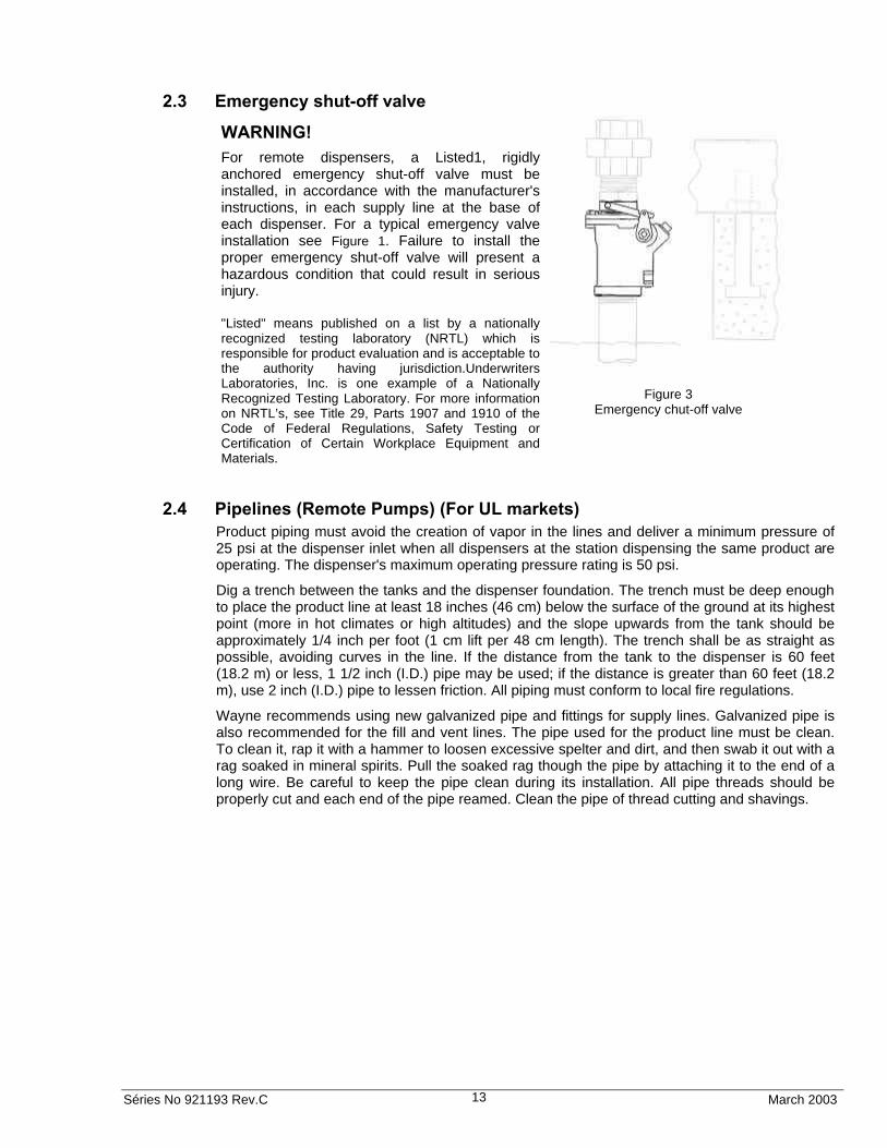
For remote dispensers, a Listed1, rigidly anchored emergency shut-off valve must be installed, in accordance with the manufacturer's instructions, in each supply line at the base of each dispenser. For a typical emergency valve installation see Figure 1. Failure to install the proper emergency shut-off valve will present a hazardous condition that could result in serious injury. "Listed" means published on a list by a nationally recognized testing laboratory (NRTL) which is responsible for product evaluation and is acceptable to the authority having jurisdiction.Underwriters Laboratories, Inc. is one example of a Nationally Recognized Testing Laboratory. For more information on NRTL’s, see Title 29, Parts 1907 and 1910 of the Code of Federal Regulations, Safety Testing or Certification of Certain Workplace Equipment and Materials.
Figure 3 Emergency chut-off valve
2.4 Pipelines (Remote Pumps) (For UL markets) Product piping must avoid the creation of vapor in the lines and deliver a minimum pressure of 25 psi at the dispenser inlet when all dispensers at the station dispensing the same product are operating. The dispenser's maximum operating pressure rating is 50 psi.
Dig a trench between the tanks and the dispenser foundation. The trench must be deep enough to place the product line at least 18 inches (46 cm) below the surface of the ground at its highest point (more in hot climates or high altitudes) and the slope upwards from the tank should be approximately 1/4 inch per foot (1 cm lift per 48 cm length). The trench shall be as straight as possible, avoiding curves in the line. If the distance from the tank to the dispenser is 60 feet (18.2 m) or less, 1 1/2 inch (I.D.) pipe may be used; if the distance is greater than 60 feet (18.2 m), use 2 inch (I.D.) pipe to lessen friction. All piping must conform to local fire regulations.
Wayne recommends using new galvanized pipe and fittings for supply lines. Galvanized pipe is also recommended for the fill and vent lines. The pipe used for the product line must be clean. To clean it, rap it with a hammer to loosen excessive spelter and dirt, and then swab it out with a rag soaked in mineral spirits. Pull the soaked rag though the pipe by attaching it to the end of a long wire. Be careful to keep the pipe clean during its installation. All pipe threads should be properly cut and each end of the pipe reamed. Clean the pipe of thread cutting and shavings.

Séries No 921193 Rev.C March 2003 14
To ensure tight pipe joints, wash all cutting oils off the threads and use a UL-Classified pipe joint sealing compound, suitable for use in devices handling petroleum-based products. Place the sealant on male threads only, being careful not to get excess inside the pipe or fittings when making up Joints.
Use nothing but ground joint unions in underground pipe work. No gasket or pipe sealing compound is required with this type of union. We recommend the use of at least one union in the dispenser supply line for accessibility in the event of trouble developing later. This should be placed as close to the tank as possible.
To prevent Zinc contamination of diesel fuels. It is recommended that all diesel fuel supply lines be non metallic, UL-Listed, and Installed per the manufacturers recommendations.
Swing joints and universal joints, or flexible connections, should be used at the ends of all horizontal runs, such as the pipe between the dispenser and the tanks. These aid in aligning the dispenser inlets with the underground piping, and prevent leaks which might develop through the settling of the tanks or heaving of the ground from heavy traffic or frost and thaw.
Block up the sloped section of products line, when installing in the trench to avoid settling. Take particular care that the lines slope continuously upward from tanks to dispenser, otherwise vapor traps may cause erratic dispenser operation. Test the lines for leaks before covering.
Breakaway devices should be used at the base of the dispenser so that damage to a dispenser will not also damage the product line. Certain applications may require emergency shutoff valves as a precaution against hazards due to fires and accidents, if these valves are required, they must be installed in accordance with the manufacturer's instructions. The automatic closing feature of the emergency shutoff valves should be tested at least once per year to ensure proper operation.
Emergency shutoff valves and breakaway devices are examples of the requirements stated in NFPA 30A, the Automotive and Marine Service Station Code. This equipment, as well as any other safety devices required by NFPA 30 and NFPA 30A, must be installed and maintained per the manufacturer's instructions.
When the dispenser has been connected and the pipe sealant is dry, the lines should be tested for leaks. Be sure to properly plug any passages to the underground tank, otherwise, over-pressurization of the tank will result in tank leaks.
To test underground lines, apply air pressure, in accordance with required local codes. While the pressure is on the line, apply soap and water solution completely around each joint. A slight leak will bubble when the solution is applied. This test must be performed /before the lines can be track filled.
On existing underground lines, an air pressure test can be performed by applying a soap and water solution to any visible joints in the line. To ensure a tight line, block any passages to the tank and apply air pressure to the line. Pressure should remain on the line for at least one hour with no loss in pressure, or in accordance with local codes. Also be sure to check unions and impact valves for leaks on the inlet valves under all the dispensers, not just the one being serviced.
Note!
Be certain to check local codes concerning line testing. In some areas a hydrostatic test as well as air pressure test is mandatory.
Séries No 921193 Rev.C March 2003 15
2.5 Check Valves (Suction Pumps Only) (For UL markets) Suction pumps require a check valve in the product lines to stop the product from draining back into the tank. Wayne recommends that double poppet foot valves are used inside the underground tank. The foot valves should be the same size as the suction lines. Foot valves designed for handling petroleum products are equipped with a coarse mesh strainer screen, the bottom of this screen is blocked off so that the product enters the valve from the side.
Some installers prefer a double poppet check valve in the line just above the tank. If a check valve is installed at the top of the tank, the end of the suction line in the tank should be equipped with a suction pipe strainer. The suction pipe strainer is similar in construction to the bottom of the foot valve and serves the same purpose.
Examine the valve carefully and remove any blocks or other means used by the manufacturer for protecting the valve in shipping. Clean the valve thoroughly with mineral spirits, because any dirt, lint, or foreign matter between the poppet and the seat will cause it to leak. The valve should be handled carefully, not dropped or thrown around. Never clamp the body of a check valve in a vise or apply a wrench to any part other than the hexagonal end of the valve. If done, it may spring or distort the valve, causing leakage or valve sticking.
Establish the length of the suction pipe in the tank to which the check valve will be attached, keeping in mind that the bottom of the suction stub must be at least four (4) inches (10 cm) off the bottom of the tank. The type of connection at the tank opening will have some bearing on the length of this pipe. Sometimes, a tank reducing plug (double tapped bushing) is used.
Wayne recommends the use of an extractable foot valve for easy and quick removal of the check valve in the tank. The importance of keeping the end of the line in the tank at least four (4) inches (10 cm) off the bottom of the tank cannot be overemphasized. Condensation is constantly occurring inside the tank and creating water on the bottom. Checking tanks regularly and keeping them clean reduces the risk of drawing water and debris into the lines and dispenser.
It is a good idea to test for leaks in both the check valve and the pipe as an assembly before installing them in the tank. Before installing the valve, pour petroleum into the check valve and pipe assembly and let it stand for an hour or two to make sure the check valve seals properly.
2.6 Connecting More Than One Pump To a Tank (Suction Dispensers) (For UL markets) If you intend to connect more than one suction dispenser to a tank, it is best to obtain a tank with enough openings to provide each pump with a separate suction line. Tanks used in remote systems normally require only one pump (submersible) to supply several dispensers; tanks designed specifically for suction dispensers will have additional openings.
Where a tank is equipped with only one opening for a suction pump connection, Wayne does not suggest the use of two or more pumps on one line; however, if this type of installation is unavoidable, it is very important that a swing check valve be used in each suction line branch, and that each valve be placed in the line as close as possible to the connection leading to the main suction line coming from the tank. This is necessary to prevent a pump from emptying the line leading to another pump instead of pulling the product out of the tank.
2.7 Fill Pipe (For UL markets) If the fill pipe is used for the insertion of the gauge (dip stick to determine the amount of product in the tank, it is important that this pipe be in a straight vertical position). The top of this pipe should be protected with a fill box so that in freezing weather, the frozen ground will not pull the tank flange loose from the tank.

Séries No 921193 Rev.C March 2003 16
2.8 Venting (For UL markets) The tank must be vented, Wayne recommends conforming to the rules of the National Fire Protection Association (NFPA). It is important that this vent line slopes slightly upward from the tank, avoiding traps or pockets, and this line should be equipped with swing joints to prevent its breaking due to settling or freezing. The top of the vent line should be at least 12 feet (366 cm) above the ground and at least 5 feet (152 cm) away from chimneys, windows or other openings. The vent outlet should be protected to minimize the possibility of blockage due to insects, nests, etc.

Séries No 921193 Rev.C March 2003 17
3 INSTALLING THE DISPENSER
A concrete foundation should be provided for the dispenser. Do not pour concrete around product or electrical risers.
Do not leave any loose dirt inside the bottom of the dispenser. Dirt and dust blown around by the motor fan or by the motion of the pulleys is likely to get attached to the V-Link belts and cause excessive wear on the belts.
Rules and regulations
By installation of fuel stations the rules and regulations of the authorities for each country must be followed. You must always be updated regarding changes and completions of the rules. CAUTION!
Danger of tipping! Follow the lifting instructions. Note the point of balance. Vertical supply risers and electrical conduits should be located in accordance with the installation drawings for the appropriate model. Proper height must be maintained to avoid undue stress on the dispenser. To install the dispenser, complete the following steps:
Figure 4 Decal
Step 1
Remove the dispenser from its shipping carton. This should have already been done when the equipment was inspected-refer to chapter 1.7"Inspect The Equipment" page 11.
Step 2
Unlock and remove the dispenser doors.
Step 3
Remove the shipping discs from the inlet unions.
NOTE!
Before performing the following steps, refer to the installation illustration (Drawing 1) page 62 for retrofit sites or Installation illustration
CAUTION
When handling the dispenser, lift only by the base or main chassis. Do not lift by the nozzle boot, hose outlet, operating lever or any external panels, this may result in dispenser damage and/or personal injury.

Séries No 921193 Rev.C March 2003 18
Unload the pump on box Installation
Figure 5 Lifting the pump
WARNING!
Danger of tipping! Bolt the pump on the base. See attachment points in the ”Installation instruction” page 61!
Step 4
Raise the dispenser up even with the island and slide the dispenser onto the island. Position the dispenser on the island in accordance with the dimensions shown on the appropriate engineering drawing in chapter 9 page 61.
Step 5
Make all piping and conduit connections and anchor the dispenser to the island using anchor bolts. The base of dispenser is provided with two bolt hole slots (3/4 inch by 1 1/2 inches) for anchoring the dispenser to the island.
1.5m
(min
.)
1.5m
(min
.)

Séries No 921193 Rev.C March 2003 19
Step 6
a) Make electrical connections as shown on appropriate engineering instruction drawing in chapter 9 page 61 and verify that electrical power source(s) match the component electrical ratings shown in Figure 6 Component Electrical Ratings and Figure 8 Submersible Pump Relay Specifications.
NOTE!
Wayne recommends employing a qualified licensed electrician for all wiring. A hazardous liquid is being handled, therefore, it is extremely important to ensure that all wiring is in accordance with the local rules, regulations, and codes discussed in Section 1.6 page 11, Local, State and Federal Codes.
CAUTION
Wires must be marked (labeled) within six (6) inches (15 cm) prior to entering the conduit union and also in the splice box to avoid component damage or shock hazard caused by incorrect wiring connections.
b) If the dispenser will be operated with a Wayne Control System, make the DATA wire connections as illustrated in the appropriate engineering drawing. These DATA wires are not required for full service (stand-alone) dispenser operations, however, if a Wayne Control System will be installed later, the DATA wires should be run at initial installation.
NOTE!
If the optional DATA wires are run they should not be physically connected to the DATA terminals in the dispenser junction box or left open ended in the dispenser splice box. Instead they should be properly terminated individually using wire nuts.
Component Electrical Ratings
Suction Pump Motor Options 1 HP, 50/60 Hz, 115/230V, 1 Phase 1 HP, 50/60 Hz, 230V, 3 Phase 1 HP, 50/60 Hz, 400V, 3 Phase 1 HP, 50/60 Hz, 230/400V, 3 Phase
Ballast Transformer Options 110VAC, 2x7W, 50/60 Hz 230VAC, 2x7W, 50/60 Hz
Figure 6 Component Electrical Ratings

Séries No 921193 Rev.C March 2003 20
3.1 Cable drawing
Cable ducts for low voltage and high voltage must be separated, to minimise the disturbances (at least 50 cm between them).
3.1.1 Routing of power cables
Cables is to be routed along the phased side of the pump as shown in Figure 7.
They shall be fastened with three appropriate cable-fasteners at the plate.
Figure 7 Routing of power cables
3.2 Emergency shutdown To be able to stop an unwanted outflow of petrol the electric control of the meters must be connected in such a way that the flow can be stopped. This function should be designed as an emergency shutdown. A reset of the emergency shutdown must not result in an automatic start of the pump motor. The emergency shutdown is marked according to national standard and should be located in such a way that it can easily be reached by the pump area supervisor. The emergency shutdown must turn off the supply power in the electrical control centre to all meter cabinets. All concerned staff must be informed of the location and function of the emergency shutdown.
Séries No 921193 Rev.C March 2003 21
3.3 Safety switch The pump is not equipped with electric circuit breaker, but the same has to be installed in the distribution board of the station.
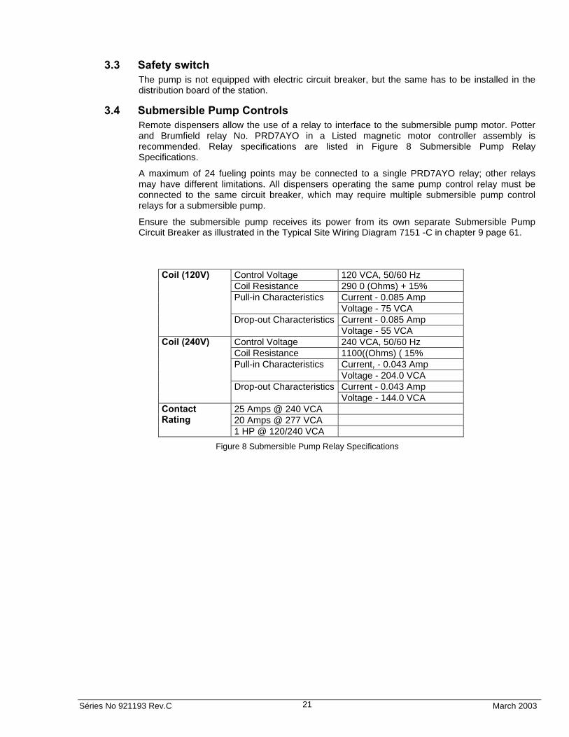
3.4 Submersible Pump Controls Remote dispensers allow the use of a relay to interface to the submersible pump motor. Potter and Brumfield relay No. PRD7AYO in a Listed magnetic motor controller assembly is recommended. Relay specifications are listed in Figure 8 Submersible Pump Relay Specifications.
A maximum of 24 fueling points may be connected to a single PRD7AYO relay; other relays may have different limitations. All dispensers operating the same pump control relay must be connected to the same circuit breaker, which may require multiple submersible pump control relays for a submersible pump.
Ensure the submersible pump receives its power from its own separate Submersible Pump Circuit Breaker as illustrated in the Typical Site Wiring Diagram 7151 -C in chapter 9 page 61.
Control Voltage 120 VCA, 50/60 Hz Coil Resistance 290 0 (Ohms) + 15%
Current - 0.085 Amp Pull-in Characteristics Voltage - 75 VCA Current - 0.085 Amp
Coil (120V)
Drop-out Characteristics Voltage - 55 VCA
Control Voltage 240 VCA, 50/60 Hz Coil Resistance 1100((Ohms) ( 15%
Current, - 0.043 Amp Pull-in Characteristics Voltage - 204.0 VCA Current - 0.043 Amp
Coil (240V)
Drop-out Characteristics Voltage - 144.0 VCA
25 Amps @ 240 VCA 20 Amps @ 277 VCA
Contact Rating
1 HP @ 120/240 VCA
Figure 8 Submersible Pump Relay Specifications

Séries No 921193 Rev.C March 2003 22
3.5 Multiple Dispenser Wiring A primary requirement in dispenser installation wiring is to provide a means for disconnecting all power connections, including the neutral, to the dispensers for safe shutdown and servicing of the units. Each dispenser can be provided with a separate control Power Circuit Breaker.
If this is not desirable or practical, several dispensers can be grouped together and tied to the same Control Power Circuit Breaker as illustrated in Typical Site Wiring Diagram 7151-C in chapter 9 page 70. A group of dispensers would then consist of all the dispensers and associated Submersible Pump Control Relay coils supplied by the same Control Power Circuit Breaker. When more than one dispenser within the group activates the same submersible pump the Relay Select lines may be tied together at the Submersible Pump Control Relay Coil terminal up to a maximum of 12 connections (24 fueling points). Where more than 12 connections activate the same submersible pump, additional relays should be used and the contacts paralleled as illustrated in 7151-C, found in chapter 9 page 70. In larger installations, dispensers can be separated into multiple groups.
WARNING
Electric Shock Hazard No connections (including neutral) may be shared between groups of dispensers. A separate Control Power Circuit Breaker must be provided for each group. Failure to do so may result in serious injury.
3.6 Hose Installation (UL) Hose assemblies should be UL Listed and installed in accordance with the manufacturer's instructions. To ensure a proper joint, wash all cutting oil off the threads and use a UL classified gasoline-resistant pipe joint sealing compound. Place the compound on male threads only; be careful not to get any excess compound inside fittings. Install the fixed end of the hose to the dispenser outlet; secure according to the instructions of the sealing compound and hose manufacturers. Install the swivel end of the hose or other swivels to the nozzle according to the manufacturer's instructions.
NFPA code requires that a Listed emergency breakaway device, designed to retain liquid on both sides of the breakaway point, must be installed on each hose dispensing Class I liquids; these devices must be installed and maintained per the manufacturer's instructions. Refer to your state and local codes for breakaway device requirements that apply to your installation.
WARNING
Use only Listed hoses and nozzles. Continuity must be present between the dispenser outlet and nozzle spout to prevent static discharge while fueling. Continuity must be checked for each outlet/hose assembly to insure that the nozzle is grounded. Failure to do so may result in a hazardous condition that could cause serious injury.

Séries No 921193 Rev.C March 2003 23
3.7 Bleeding Product Lines (Remote Dispenser) Make sure the power to the appropriate submersible pump is OFF.
NOTE!
To avoid severe damage to the dispenser, all air and air pockets must be bled from the product trunk lines before attempting to dispense product.
To bleed air from a trunk line, remove the pipe plug from the safety impact valve on the dispenser farthest from the storage tank.
Attach a flexible hose to the pipe plug opening in the safety impact valve. Energize the appropriate submersible pump and allow the air to bleed out of the trunk line into a test can until product flows into the test can. De-energize the submersible pump and replace the pipe plug. Repeat the procedure for each product and each trunk line.
3.8 Priming Suction Pumps Suction pumping units must be primed before their initial operation; it is not advisable to run any type of internal gear pump dry during the priming process. Remove the cover and the check valve and fill up with liquid in the pumping unit before starting the pump for the first time, see picture.
Figure 9 Priming Suction Pumps

Séries No 921193 Rev.C March 2003 24
Figure 10 Priming Suction Pumps (Duo with one twin meter)
Remove the tube.
Remove the cover and the check valve

Séries No 921193 Rev.C March 2003 25
3.9 Above Ground Storage Tanks When installing Wayne suction pumps in locations with above ground tanks and a pressure regulator valve, a pipe plug with an orifice (Wayne part number 129881) must be added into the pumping unit for optimum performance. Refer to the drawing Figure 11 Location of Pipe Plugs in Pumping Unit.that shows where to add the pipe plug.
Above ground tank installations with a pressure regulator valve may not allow the pumping unit to generate enough vacuum to keep the air chamber from over filling with fuel and allowing it to discharge from the vent. The addition of this orifice plug will prevent this problem.
Figure 11 Location of Pipe Plugs in Pumping Unit. The pipe plug is only required for above ground storage tanks.
Pipe plug orifice exploded view
Prime plug
Remove end cap to install pipe plug

Séries No 921193 Rev.C March 2003 26
4 START-UP PROCEDURE
Power should be OFF. Always turn the dispenser control power circuit breaker OFF before accessing the inside of the dispenser.
4.1 Hose Position Coding In order to set up the dispenser properly, the installer has to understand hose position coding. Unit Prices and Totals are given in hose position order; for an example of hose position coding see Figure 4-1. When viewing the dispenser from the junction box side, the "X" hose position is always the hose on the far left.
Figure 12 Hose Position Coding for Century Series. These positions are critical for unit price programming from a system.
DISPLAY X1A
SIDE A
SIDE B
VIEW OF PULLEY
MODEL 3/G3387 SUCTION & DISPENSER
DISPLAY X1B
NOZZLE 1A
NOZZLE 1B
X
SIDE A
SIDE B
VIEW OF PULLEY
MODEL 3/G3399 SUCTION & DISPENSER
DISPLAY X1A / AA4A
DISPLAY X1B / AA4B
NOZZLE 1A
NOZZLE 1B
X
NOZZLE 2A
NOZZLE 2B
AA
SIDE A
SIDE B
VIEW OF PULLEY
MODEL 3/G3397 3/G3397P/FP 3G3397P/FC
SUCTION & DISPENSER
DISPLAY X1A
DISPLAY X1B
NOZZLE 1A
NOZZLE 1B
X
VIEW OF PULLEY
DISPLAY X1A / AA2A
SIDE A
SIDE B
MODEL 3/G3498 SUCTION & DISPENSER
DISPLAY Y1B / Z2B
NOZZLE 1A
NOZZLE 1B
X
NOZZLE 2A
NOZZLE 2B
AAZY

Séries No 921193 Rev.C March 2003 27
Hose Position Coding for Century Series. These positions are critical for unit price programming from a system.
4.2 Nozzle Switch Check Check the operation of the nozzle switch as follows:
1. Remove the nozzle from the nozzle boot. Lift the drive handle in all the extension (if the model is not auto-on), driving the micro switch in the receptacle. An “on” switch will be indicated by the “displays”, showing 8 digits and, afterwards, the unit price and zero in the “displays”, for “Volume” and “Total to pay”.
2. Lower the Lift-to Start lever to the down position (replace the nozzle in the nozzle boot, on the Auto-on activated models) and check that the switch turns OFF.
MODEL 3/G3388 SUCTION & DISPENSER
DISPLAY X1A / AA4A
SIDE A
SIDE B
VIEW OF PULLEY
MODEL 3/G3389 SUCTION & DISPENSER
DISPLAY X1B / AA4B
NOZZLE 1A NOZZLE 2A
NOZZLE 1B NOZZLE 2B
X AA
DISPLAY X1A
SIDE A
SIDE B
VIEW OF PULLEY
DISPLAY AA4B
NOZZLE 1A
NOZZLE 1B
X AA
DISPLAY X1A / AA4A
SIDE A
SIDE B
VIEW OF PULLEY
MODEL 3/G3490 SUCTION & DISPENSER
DISPLAY X1B / AA4B
NOZZLE 1A
NOZZLE 1B
X
NOZZLE 4A
NOZZLE 4B
AA
NOZZLE 3A
NOZZLE 3B
Z
NOZZLE 2A
NOZZLE 2B
Y
DISPLAY X1A / AA4A
SIDE A
SIDE B
VIEW OF PULLEY
MODEL 3/G3390 SUCTION & DISPENSER
DISPLAY X1B / AA4B
NOZZLE 1A
NOZZLE 1B
X
NOZZLE 3A
NOZZLE 3B
AA
NOZZLE 2A
NOZZLE 2B
Y

Séries No 921193 Rev.C March 2003 28
4.3 Meter Check
NOTE!
Except at calibration/verification the power to the pulser should be turned off when handling it.
4.3.1 Pumps Calibration.
Only one side of meter can be calibrated of each time. The valid calibration volumes are 5, 10 and 20 litres. A verification should be done after each calibration.
1. Wet the can and return the product to the tank, letting the product drain for 10 seconds.
2. Identify the calibration door of the meter that need calibration and remove the respective seal.
3. Remove the nozzle corresponding to the meter to be calibrated.
4. Actuate the handle of the nozzle boot (if it is no “Auto-on”).
5. Observe that motor and the solenoid are on.
6. Open the calibration door of the meter, certifying the door is fully open.
Figure 13 Calibration door
In the picture the calibration door for the A-side is closed and the door for the B-side is opened.
7. Fill the can (5, 10 or 20 liters) up to the zero mark. Considering that the system is not yet calibrated, the display will show a volume not totally corresponding to the volume contained in the can.
8. Close the calibration door.
9. Observe if the motor and the solenoid are off.
10. Return the nozzle to rest position.
11. Empty the can.
12. If several meters supply one nozzle, repeat the procedure of steps 5 to 8 for the next meter.
13. To check the calibration, fill the can until the display shows the correct volume. The can volume shall now be within the limits approved by the authorities. On the contrary, a new calibration shall be conducted.
Séries No 921193 Rev.C March 2003 29
4.4 Link Belt Adjustment 4.4.1 Z-profile belt
NOTE!
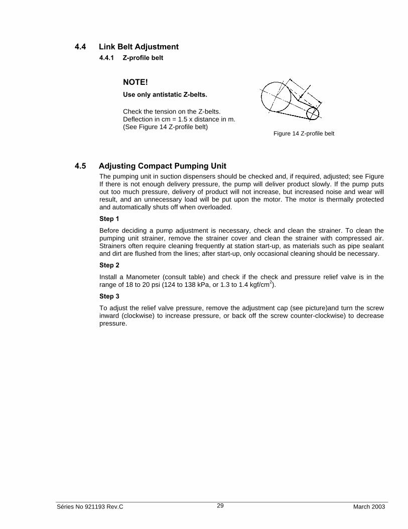
Use only antistatic Z-belts.
Check the tension on the Z-belts. Deflection in cm = 1.5 x distance in m. (See Figure 14 Z-profile belt)
Figure 14 Z-profile belt
4.5 Adjusting Compact Pumping Unit The pumping unit in suction dispensers should be checked and, if required, adjusted; see Figure If there is not enough delivery pressure, the pump will deliver product slowly. If the pump puts out too much pressure, delivery of product will not increase, but increased noise and wear will result, and an unnecessary load will be put upon the motor. The motor is thermally protected and automatically shuts off when overloaded.
Step 1
Before deciding a pump adjustment is necessary, check and clean the strainer. To clean the pumping unit strainer, remove the strainer cover and clean the strainer with compressed air. Strainers often require cleaning frequently at station start-up, as materials such as pipe sealant and dirt are flushed from the lines; after start-up, only occasional cleaning should be necessary.
Step 2
Install a Manometer (consult table) and check if the check and pressure relief valve is in the range of 18 to 20 psi (124 to 138 kPa, or 1.3 to 1.4 kgf/cm2).
Step 3
To adjust the relief valve pressure, remove the adjustment cap (see picture)and turn the screw inward (clockwise) to increase pressure, or back off the screw counter-clockwise) to decrease pressure.

Séries No 921193 Rev.C March 2003 30
Figure 15 Compact Pumping Unit
4.6 Fluorescent Lights If the dispenser is lighted, turn on the light circuit breaker and ensure that all of the fluorescent lights operate correctly. Replace any fluorescent light bulbs that fail to illuminate.
4.7 Totalizer Readings Totals can be read off at the display for the respective pump sides. The pump must not be activated, not even disengaged during this operation. Press the stop-key. Volumes for each grade will be displayed for 5 seconds.
4.7.1 Electro-mechanical volume totalizer (Option)
There is a seven digit electro-mechanical volume totalizer located on the side of the head. Read and record the totals. The initial readings must be given to the station manager in order to maintain accurate station totals.
4.7.2 Volume Totalizer Through Preset
In the Preset, press the keys “1” and “2” simultaneously. The least significant six (6) digits of the data value appear on the “Volume” display. The higher order non-zero digits of the data value, if present, appear as blanks. In the “Unit price” display appear corresponding nozzles. Ex. A1, B1, A2, B2, A3, B3, A4, B4.
Install a pressure gauge

Séries No 921193 Rev.C March 2003 31
4.8 Coalescent Filter Pump – Start Up Procedure Before beginning the supply start up, check if the inlet valve 1 and outlet valve 3 are closed and the by-pass valve 2 is open, and during at least one working day (or 2000 liters) the fuel shall be recirculated, returning the above mentioned volume to the tank. After this line cleaning procedure, put the valves in reverse position inlet 1 and outlet 3 opened and by-pass 2 closed.
CAUTION!
This recommendation for initial by-pass is important to increase the service life of the filter.
WARNING!
The purge valve shall be open until the pressure vessel is full in order to facilitate the line flow.
Figure Coalescent Filter
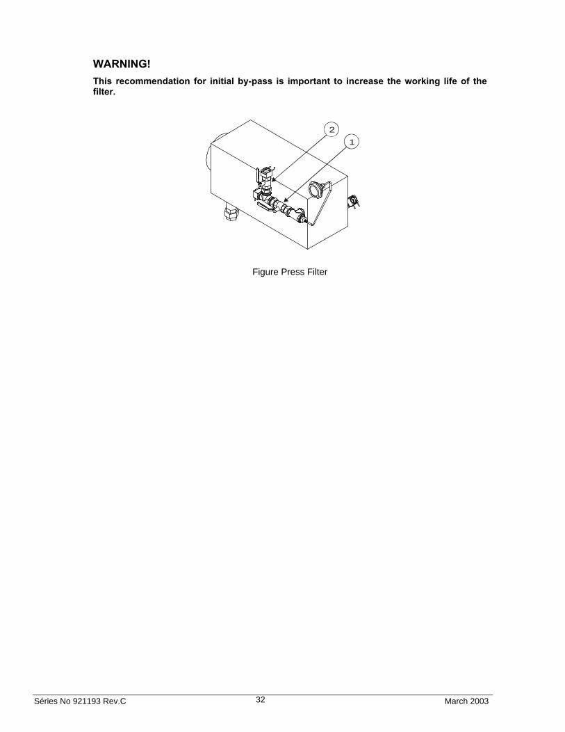
4.9 Press Filter Pump – Start Up Procedure Before beginning the start up, check if inlet valve 1 is closed and by-pass valve 2 is open, and during at least one working day (or 2000 liters) the fuel shall be recirculated, returning the above recommended volume to the tank. After this line cleaning procedure, put the valves in reverse form inlet 1 open and by-pass 2 closed.
1
2
3
Séries No 921193 Rev.C March 2003 32
WARNING!
This recommendation for initial by-pass is important to increase the working life of the filter.
Figure Press Filter
1
2

Séries No 921193 Rev.C March 2003 33
5 COMPUTER OPERATION
5.1 Introduction You will need to access the maintenance mode in order to program functions and/or view statistics. The function and statistics data appear in the money, volume, and unit price display windows. The infrared interface is similar to a television remote control. It has 16 buttons (see Figure 23). Use the infrared interface to access dispenser functions. This interface uses only the pump display for user feedback. There is no additional display.
5.2 Programming functions Change Unit Price (F03) page 40 Checking the Electronic Totals (S11) page 36 Pump Start up page 45 Exit Function page 35 Filling Modes (F01) page 36 Exit (F00) page 35 Password Change (F33) page 36 Access to Functions page 33 Note! The Infrared interfaces only suitable for use in unclassified (non-hazardous) locations. See Figure 24 Hazardous Zone Diagram. (UL) and Figure 25 Hazardous Location Diagram (IEC).
Figure 16 Remote controlHoofer
Doofer
5.3 Access to functions Access the programming mode by pressing one of the following keys:
1 Station manager entry using station manager password.
2 Operator entry using operator password.
CLEAR Weights and Measures entry using weights and measures password.
1 2
3 4
5 6
7 8
9 0
MM
$
L
P-6 A99
E-06E5
CC
Memory Checksum
Memory checksum W&M part

Séries No 921193 Rev.C March 2003 34
The programming mode asks you for a password twice before allowing access to the functions. A 10-second time-out is built into the password entry code.
After 3 seconds, the display shows:
1 2
3 4
5 6
7 8
9 0
MM
$
L
PASS 1
- - - - - -
CC
When the word PASS 1 appears on the sale display, you have 10 seconds to start entering the password. The timer restarts after you press a key. When you finish entering the password and press ENTER (=M).
PASS 2 appears in the sale display window, prompting you to enter the password again.
The display will show:
1 2
3 4
5 6
7 8
9 0
MM
$
L
PASS 2
- - - - - -
CC
Note1!
If you press nothing more, press <ENTER> (=MM) or press the wrong password, or there’s no confirmation after pressing the password and the <ENTER> key, after about 10 seconds the computer will leave this function automatically.
Note 2!
If you press the wrong keys, press <CLEAR> (=CC) key to erase the last digit you typed.
Press again the password to confirm and press <ENTER>

Séries No 921193 Rev.C March 2003 35
Press <ENTER>
The Display shows the function screen
1 2
3 4
5 6
7 8
9 0
MM
$
L
4.01
7.25.00
CC
Software version Software date
F--
When you enter the programming mode, the unit price display windows show "F - - ", the money display window shows the software version number, and the volume display window shows the date of the software version. To edit or view specific functions, enter any function number using the number keys and press ENTER. The corresponding number appears in the money display window.
5.4 Exit (F00) Use this function to select one of three maintenance mode exits.
Type 00
Press <ENTER> (=M)
1 2
3 4
5 6
7 8
9 0
MM
$
L
- - - - - -
F00 CC
.01 Do not exit and do not save changes
.02 Exit, but do not save changes
.03 Exit and save changes
Séries No 921193 Rev.C March 2003 36
5.5 Password Change (F33) Dashes appear in the money display window, and the word PASS appears on the volume display. When you begin editing, the money display goes blank and dashes appear instead of the regular entries. Enter the new password twice. The sub-function numbers are defined as follows:
.01 Station Manager Password, maximum of 6 characters (Use numbers only)
.02 Station Operator Password, maximum of 6 characters (Use numbers only)
.03 Weights and Measures Password, maximum of 6 characters (Use numbers only)
5.6 Filling Modes (F01) Selected configuration parameters defined as follows:
.01 Serial Mode, dispenser controlled by site controller via serial link
.02 Stand Alone Mode, dispenser not supervised by a site controller
.03 Serial W&M Mode, same as 01 but volume decimal point format forced to .xxx volume units
.04 Stand Alone W&M Mode.
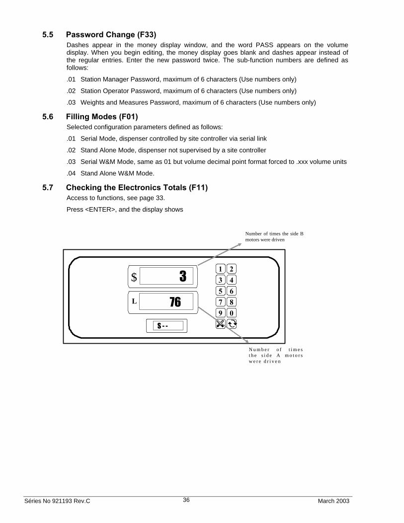
5.7 Checking the Electronics Totals (F11) Access to functions, see page 33.
Press <ENTER>, and the display shows
Number of times the side B motors were driven
N u m b e r o f t i m e s t h e s i d e A m o t o r s w e r e d r i v e n
1 2
3 4
5 6
7 8
9 0
MM
$
L
3
76
S - - CC

Séries No 921193 Rev.C March 2003 37
Type 11
Press the <UP> or <DOWN> keys to enter statistical mode, and the display shows:
1 2
3 4
5 6
7 8
9 0
MM
$
L
- - - - - -
S 11 CC
Press <ENTER> to access the function and view the last dispensing.
1 2
3 4
5 6
7 8
9 0
MM
$
L
590.11
11.11 CC
The volume above are example.
Press <UP> to read the volume total of the other nozzle.
1 2
3 4
5 6
7 8
9 0
MM
$
L
54.91
11.12 CC

Séries No 921193 Rev.C March 2003 38
If you press <UP> will read the money totals of nozzle 1A
1 2
3 4
5 6
7 8
9 0
MM
$
L
5903.11
11.21 CC
To read other total press.
1 2
3 4
5 6
7 8
9 0
MM
$
L
21
82
S - - CC
Exit, see page 35.
5.7.1 Access to the statistic model
S11 – GENERAL TOTAL BY LOGICAL NOZZLE – SIDE A
Exemple: S.11.11
TN
11.11
StatisticFunctionSide A
Unit PriceDisplay
Séries No 921193 Rev.C March 2003 39
The substatistical numbers have the format “.TN” :
T = type of totals 1 = volume 2 = total in cash 3 = total in credit 4 = total on demand 5 = number of dispensing done with console 6 = number of dispensing done without console N = number of the logical nozzle 0-8, where 0 = not configured
At least six (6) data digits shows up at the window “VOLUME”. The complement of data digits different from “zero”, if any, shows at the window “TOTAL SALES”. The decimal “zeros” are blank.
S12 – GENERAL TOTAL BY LOGICAL NOZZLE – SIDE B
The substatistical numbers have the format “.TN” :
T = type of totals 1 = volume 2 = total in cash 3 = total in credit card 4 = total on demand 5 = number of dispensings done with console 6 = number of dispensings done without console N = number of the logical nozzle 0-8, where 0 = not configured
At least six (6) data digits shows up at the window “VOLUME”. The complement of data digits different of “zero”, if any, shows at the window “TOTAL SALES”. The decimal “zeros” are blank.
5.7.2 Mode “Statistics”
S01 – PARTIAL TOTALS (W/O SHIFT) PER LOGIC NOZZLE – SIDE A
At least six (6) data digits show up at the window “VOLUME”. The complement of data digits different from “zero”, if any, shows at the window “TOTAL SALES”. The non-significative “zeros” are blank.
PROCEDURE TO ERASE SHIFT TOTALS – SIDE A
- Access the function S01
- Press “ENTER” (the display shows UNIT PRICE the subfunction “1.11” and in display VOLUME the registered volume)
- Press “#”(the display shows PAYING TOTAL “CLEAR” and in display VOLUME “TOTALS”
- Press “ENTER” (the display shows PAYING TOTAL “PASS”)
- Type PASS 42
- Press “ENTER” (All shift totals are zeroed)

Séries No 921193 Rev.C March 2003 40
S02 – SHIFT TOTALS BY LOGICAL NOZZLE – SIDE B
The substatistical numbers have the format “.TN” :
T = type of totals 1 = volume 2 = total in cash 3 = total in credit card 4 = total on demand 5 = number of dispensings done with console 6 = number of dispensings done without console N = number of the logical nozzle 0-8, where 0 = not configured
At least six (6) data digits show up at the window “VOLUME”. The complement of data digits different of “zero”, if any, shows at the window “TOTAL SALES”. The non-significative “zeros” are blank.
- Press “Next” to go forward
Exit, see page 35.
5.8 Changing Unit price (F03) 5.8.1 Changing prices on Side A
Access to functions, see page 33.
The Display shows the function screen
- Step 1 – Press 03 and press <ENTER>, and the display shows:
1 2
3 4
5 6
7 8
9 0
MM
$
L
- - - - - -
F03 CC

Séries No 921193 Rev.C March 2003 41
- Step 2 - Press <ENTER> and the display shows:
1 2
3 4
5 6
7 8
9 0
MM
$
L
- - - - - -
1.300
3.01 CC
Note!
To access the other unit price press <Next>.
Sub-Function 3.01 is responsible for changing unit price of fuel at nozzle 1 on side A, and so on, according to the table below:
Sub-Function Credit Prices
Nozzle ( Position )
Side
3.01 1 A 3.02 2 A
Sub-Function Cash Prices
Nozzle ( Position )
Side
3.11 1 A 3.12 2 A
Pump Side Identification
Séries No 921193 Rev.C March 2003 42
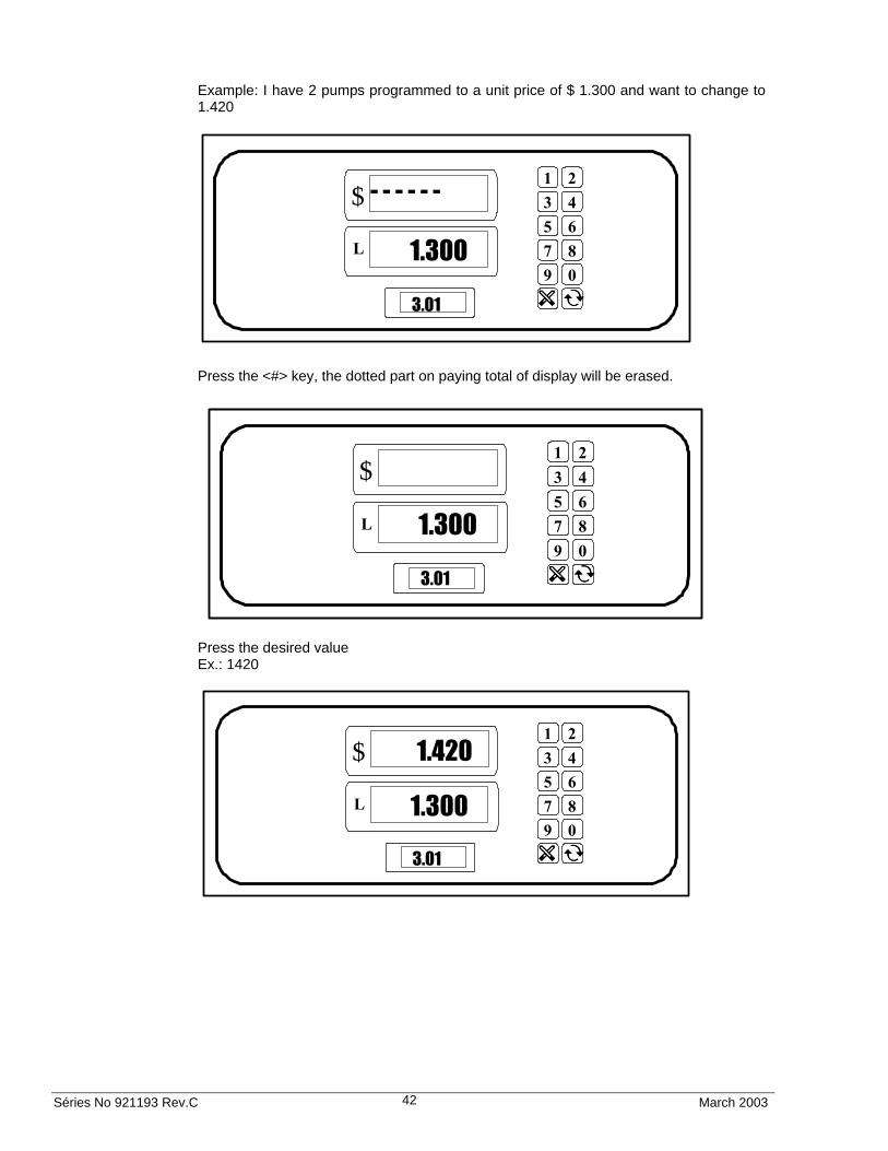
Example: I have 2 pumps programmed to a unit price of $ 1.300 and want to change to 1.420
1 2
3 4
5 6
7 8
9 0
MM
$
L
- - - - - -
1.300
3.01 CC
Press the <#> key, the dotted part on paying total of display will be erased.
1 2
3 4
5 6
7 8
9 0
MM
$
L
1.300
3.01 CC
Press the desired value Ex.: 1420
1 2
3 4
5 6
7 8
9 0
MM
$
L
1.420
1.300
3.01 CC

Séries No 921193 Rev.C March 2003 43
Press <ENTER>, and the display shows
1 2
3 4
5 6
7 8
9 0
MM
$
L
- - - - - -
1.420
3.01 CC
To change from one Sub-Function to another use the <NEXT> key (Ex.: from 3.01 to 3.02).
The same procedure applies to change the cash prices. ( Sub functions 3.11 to 3.12, see table)
To save all changes follow the procedure of “F00” exiting, value 3. (see page 35)
5.8.2 Changing prices on Side B
Access to functions, see page 33.
- Step 1 – Press 04 and press <ENTER>, and the display shows:
1 2
3 4
5 6
7 8
9 0
MM
$
L
- - - - - -
F04 CC
- Step 2 - Press <ENTER>
1 2
3 4
5 6
7 8
9 0
MM
$
L
- - - - - -
1.300
4.01 CC

Séries No 921193 Rev.C March 2003 44
The Sub-Function 4.01 is responsible for changing unit price of fuel at nozzle 1 on side B, and so on, according to the table below:
Sub-Function Credit Prices
Nozzle ( Position )
Side
4.01 1 B 4.02 2 B
Sub-Function Cash Prices
Nozzle ( Position )
Side
4.11 1 B 4.12 2 B
Example: I have 2 pumps programmed to a unit price of $ 1.300 and want to change to 1.420
1 2
3 4
5 6
7 8
9 0
MM
$
L
0.00
0.00
1.300 CC
Press the <#> key, the dotted part on paying total of display will be erased.
1 2
3 4
5 6
7 8
9 0
MM
$
L
1.300
4.01 CC
Séries No 921193 Rev.C March 2003 45
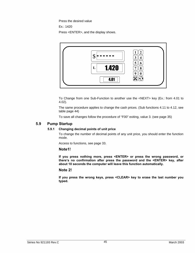
Press the desired value
Ex.: 1420
Press <ENTER>, and the display shows.
1 2
3 4
5 6
7 8
9 0
MM
$
L
- - - - - -
1.420
4.01 CC
To Change from one Sub-Function to another use the <NEXT> key (Ex.: from 4.01 to 4.02).
The same procedure applies to change the cash prices. (Sub functions 4.11 to 4.12, see table page 44)
To save all changes follow the procedure of “F00” exiting, value 3. (see page 35)
5.9 Pump Startup 5.9.1 Changing decimal points of unit price
To change the number of decimal points of any unit price, you should enter the function mode.
Access to functions, see page 33.
Note1!
If you press nothing more, press <ENTER> or press the wrong password, or there’s no confirmation after press the password and the <ENTER> key, after about 10 seconds the computer will leave this function automatically.
Note 2!
If you press the wrong keys, press <CLEAR> key to erase the last number you typed.

Séries No 921193 Rev.C March 2003 46
Step 1- Select function 14 and press <ENTER> twice and the display shows:
1 2
3 4
5 6
7 8
9 0
MM
$
L
- - - - - -
1
14.00 CC
Step 2- Using the <NEXT> key, select Sub function 14.04, and the display shows:
1 2
3 4
5 6
7 8
9 0
MM
$
L
- - - - - -
3
14.04 CC
Note!
In this manual example, the unit price value is $1.000 (three decimal points).
Example of UP Function 14.04 1000 0 100.0 1 10.00 2 1.000 3

Séries No 921193 Rev.C March 2003 47
Press the <#> key, the dotted part of paying total will be erased.
1 2
3 4
5 6
7 8
9 0
MM
$
L
3
14.04 CC
Press the desired value and press <ENTER>. Ex.: 2
1 2
3 4
5 6
7 8
9 0
MM
$
L
- - - - - -
2
14.04 CC
Press <ENTER> to return to function 14, press <CLEAR> to return to function menu, and follow procedure at function F00, value 3 to save the changes. To save all changes follow the procedure of “F00” exiting, value 3. (see page 35)
5.9.2 Changing decimal points of Paying Total
Function 14.02
- Step 1 – Select Function 14 and press <ENTER>, and the display shows:
1 2
3 4
5 6
7 8
9 0
MM
$
L
- - - - - -
1
14.00 CC

Séries No 921193 Rev.C March 2003 48
- Step 2 – Using the <NEXT> key, select Sub-Function 14.02, and the display shows:
1 2
3 4
5 6
7 8
9 0
MM
$
L
- - - - - -
2
14.02 CC
- Step 3 Press #
- Step 4 – Press the desired value and press <ENTER>, and the display shows:
Ex.: 1
1 2
3 4
5 6
7 8
9 0
MM
$
L
- - - - - -
1
14.02 CC
Press <CLEAR> to return to function 14 and follow as described at “Exiting functions (Function zero)”. To save all changes follow the procedure of “F00” exiting, value 3. (see page 35)
5.9.3 Changing decimal points of Volume
Function 14.03
- Step 1 – Select function 14 and press <ENTER>, and the display shows:
1 2
3 4
5 6
7 8
9 0
MM
$
L
- - - - - -
1 14.00 CC

Séries No 921193 Rev.C March 2003 49
- Step 2 – Using the <NEXT> key, select Subfunction 14.03, and the display shows:
1 2
3 4
5 6
7 8
9 0
MM
$
L
- - - - - -
2 14.03 CC
- Step 3 Press #
- Step 4 – Press desired value number and press <ENTER>, and the display shows:
Ex.: 3
1 2
3 4
5 6
7 8
9 0
MM
$
L
- - - - - -
3
14.03 CC
To save all changes follow the procedure of “F00” exiting, value 3. (see page 35)
NOTE:
The UL master-satellite models have a “satellite in use” indication in a display besides the unit price, as show in the picture. Once the satellite nozzle is activated, the display shows dashes going up.
1 2
3 4
5 6
7 8
9 0
MM
$
L
- - - - - -
3
14.03 CC
Séries No 921193 Rev.C March 2003 50
6 DEMOUNTING
6.1 Preparations Read chapter 2 page 12 and forward.
WARNING!
To prevent damage which may result in electric shock or fire, disconnect the main power (motors and electronic head) prior to any work
6.2 Drain fuel from the pump It is important that the pump is emptied of fuel before demounting.
Seal the inlet pipes with a flange with gasket. Depending on the pump model between one and two pump units must be emptied and seal.
If needed, ask a transportation company for special regulations.

Séries No 921193 Rev.C March 2003 51
7 OPERATION
7.1 Introduction The dispensers are one or two inlet dispensers, with one or two outlets (depending on model). Each side of the dispenser represents a fueling point.
The dispenser is equipped with one unit price per nozzle. Unit price must be set to operate. If the dispenser is connected to a Management Control System, each dispenser must have a unique fueling point number set for communication with a Management Control System.
Select the desired product. The dispenser is turned on by removing the nozzle from the nozzle boot and lifting the operating lever (the lever is not lifted with the Auto-On models). The sales display will show 8s, blanks and then reset to zero.
The pump motor starts at the end of the reset cycle and the solenoid valves open approximately 3-5 seconds later.
To complete the sale, lower the operating lever, replace the nozzle in the nozzle boot and the pump motor will be switched OFF.
7.2 Portable Tanks and Containers Portable containers of 12 gallons (45 liters) or less shall not be filled while they are in or on a motor vehicle. Filling portable containers, especially when they are sitting on a non-conductive surface such as a floor mat or a plastic bedliner in the back of a pick-up truck, can present a possible safety hazard and should avoided as so stated in the following WARNING:
WARNING
FIRE HAZARD! The flow of gasoline through the dispenser nozzle can produce static electricity, which can cause a fire if gasoline is pumped into an ungrounded gasoline container. To avoid static buildup and the possible resulting serious injury:
• Place approved container on the ground. Do not fill the container in the vehicle or truck bed.
• Keep the nozzle in contact with the can or container while filling. Do not use an automatic pump handle (latch-open) device.
7.3 Operation of the Preset (Option) Dispensers with the preset option will have a preset keypad assembly installed in them. This option allows the customer, or attendant, to input the amount of product desired, either in volume or money, prior to the beginning of the sale. The following sections describe typical operational scenarios using the preset option.

Séries No 921193 Rev.C March 2003 52
7.3.1 Twelve button keyboard
• Preset Operation
1. Pump Display shows last sale
2. Operator presses a digit key.
The display starts to blink
If this is a numeric key the number will be indicated at the default panel (volume or money panel), the other panel shows dashes.
If this is the C key, the display will switch to the Money/Volume line, in case of money selected, dashes are indicated on the volume panel.
Pressing the “M” key cancels the preset operation.
3. Display will continue to blink showing the entered numbers at one panel and dashes at the other until the operator lifts the nozzle.
4. The display starts the reset cycle and stop blinking.
5. The normal filling information will be indicated at the display.
6. At the end of the sale the display shows the sale (without blinking and showing the preset entry).
1 23 45 67 89 0M C

Séries No 921193 Rev.C March 2003 53
7.3.2 Five button keyboard
• Preset Operation
1. Pump display shows last sale
2. Operator presses a digit key.
The display starts to blink.
There are 3 fixed values of 10, 20 and 50.
Multiple press of any of the fixed preset value buttons will be added to the preset value.
For example, if the button 10 is pressed, 10 will be indicated,
next if 50 is pressed, then 60 (10+50) will be indicated,
next if 20 is pressed, then 80 will be indicated as preset value at the display.
If this is a numeric key the number will be indicated at the default panel (volume or money panel), the other panel shows dashes.
If this is the C key, the display will switch to the Money/Volume line, in case of money selected, dashes are indicated on the volume panel.
Pressing the “M” key cancels the preset operation.
3. Display will continue to blink showing the entered numbers at one panel and dashes at the other until the operator lifts the nozzle.
4. The display starts the reset cycle and stop blinking.
5. The normal filling information will be indicated at the display.
6. At the end of the sale the display shows the sale (without blinking and showing the preset entry).
10 Softkey 110
20 Softkey 220
50 Softkey 350
C Softkey 4Mon./Vol.
M Clear

Séries No 921193 Rev.C March 2003 54
7.4 Health Note Be advised that petroleum fuel and fuel vapors can damage your health.
Warning
Never run a leaking pump! Be careful with the environment and mind the skidding risk; take care of leaching fuel immediately.
Adequate personal safety equipment should be used by maintenance of the equipment (gloves, breathing mask, glasses etc.).
7.5 Hazardous Zone Areas It is important to know the Hazardous Zone area around the dispenser as shown in Figure .
Zones Risk types Protection class Example
0 A risk area where explosive gas mixture exists all the time or during a long period.
Exia In a tank.
1 A risk area where explosive gas mixture may exist occasionally during normal operation.
Exd, Exe, Exib, Exp, Exia, Exs, Exm
Within the meter. (within the hydraulic areas and pillar of the pump, see Figure 17 and Figure 18.
2 A risk area where explosive gas mixture is not expected to exist during normal operation and, if it should exist anyway, in that case seldom and during a short period of time.
Exd, Exe, Exib, Exp, Exia, Exs, Exo, Exq, Exm
see Figure 17 and Figure 18.
Possible risk ofirreversible effects.Also danger ous:may cause lungdamage if swallowed.
Keep out of the reach of children.After contact with skin wash immediately withsoap and water.If swallowed do not induce vomiting: seekmedival advice immediately.do not breath fumes or vapour.avoid release to the environment. Do notempty into drains.
Contains: Gas oil - unspecifiedContains: Gasoline Benzene - unspecified
UNLEADED GASOLINE
EXTREMELYFLAMMABLE
May cause cancer.Also danger ous: may causelung danger ous: may causelung damage if swallowed.Irritating to skin.
Avoide exposure - obtainspecial instructiond before use.In case of accident, or if youfeel unwell, seek medicaladvice immediately (show thelabel where possible). Aftercontact with skin washimmediately with soap andwater.
If swalloed do not inducevomiting: Seek medical adviceemmediately.Avoide release to theenvironment. Keep out of thereach of children. Do notempty into drains.
DIESEL OIL

Séries No 921193 Rev.C March 2003 55
7.5.1 Hazardous Zone UL
Figure 17 Hazardous Zone Diagram. (UL)
Front and top views showing horizontal and vertical distances.

Séries No 921193 Rev.C March 2003 56
7.5.2 Hazardous Zone IEC
Figure 18 Hazardous Zone Diagram (IEC)
IP23
IP54
IP67
IP54
IP23
8” 8”
2”
0.8”
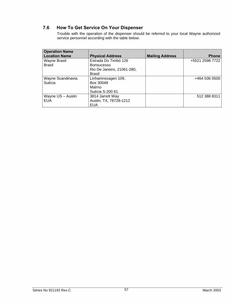
Séries No 921193 Rev.C March 2003 57
7.6 How To Get Service On Your Dispenser Trouble with the operation of the dispenser should be referred to your local Wayne authorized service personnel according with the table below.
Operation Name Location Name
Physical Address
Mailing Address
Phone
Wayne Brasil Brasil
Estrada Do Timbó 126 Bonsucesso Rio De Janeiro, 21061-280, Brasil
+5521 2598 7722
Wayne Scandinavia Suécia
Linhamnsvagen 109, Box 30049 Malmo Suécia S-200 61
+464 036 0500
Wayne US – Austin EUA
3814 Jarrett Way Austin, TX, 78728-1212 EUA
512 388 8311

Séries No 921193 Rev.C March 2003 58
8 PREVENTIVE MAINTENANCE
8.1 Water Damage It is recommended that the following precautions be taken to prevent water from getting inside the dispenser:
If it is necessary to clean the dispenser, wipe it off with a damp cloth. Do not spray the dispenser with water.
Do not use abrasive cleaners on the bezel. Use only mild soap and water with a soft cloth. Do not use gasoline or other petroleum based products to clean the dispenser.
Before removing the bezel, wipe off any water lying along the top edge of the dispenser so it will not run inside when the bezel is removed.
Care must be taken to prevent rain from getting inside if the bezels must be removed during rainy weather.
Always remove snow and ice from the pump.
8.2 Maintenance Guidelines A correctly installed, properly maintained dispenser, will seldom require emergency service.
Check the dispenser for internal and external leaks regularly. Check nozzles, swivels, hoses, and joints for leaks and wear. Have all defects repaired immediately.
WARNING!
Never run a leaking pump!
(Failure to observe this information results in immediate danger to life.)
Test the tank for water regularly. Water in petroleum is not only a source of engine trouble, but will also cause damage to the dispenser.
Do not abuse the hose by trying to stretch it to reach an automobile. This will cause early failure at the couplings.
8.3 Cleaning of filters A dirty strainer screen will slow down the delivery of petroleum. If the underground installation is a new one, it may be necessary to clean the strainer screen two or three times the first few days of operation to remove debris and pipe sealant. After this, occasional cleaning is all that should be required.
NOTE!
Before removing the fuel filter or strainer assembly turn of the circuit breaker to the pump.
NOTE!
Replacement fuel filters can be obtained from the vendor or from Wayne Division, Dresser Industries, Inc.
1. Wash the screen in gasoline and dislodge lint and other foreign particles with compressed air. Check for leakage after reinstalling.
2. All keylock cylinders and locking mechanisms should be periodically checked and lubricated.

Séries No 921193 Rev.C March 2003 59
8.3.1 Inlet filter (Europe)
Remove the tube and filter (see Figure 19 Inlet filters). The filter can then be rinsed in water and/or blown with pressure air.
Figure 19 Inlet filters
8.3.2 Inlet filter (US)
The strainer is removed for cleaning by unfastening the cap; see Figure 20 Strainer Assembly (US). Place a container under the cap to catch the petroleum and sediment.
Figure 20 Strainer Assembly (US)
Inlet filter
CAP
STRAINER
Séries No 921193 Rev.C March 2003 60
8.3.3 After filter cleaning:
Put on the power and check the functions. Make sure that there is no leakage.
WARNING!
Never run a leaking pump!
(Failure to observe this information results in immediate danger to life.)
8.3.4 Coalescent Filter
The filter elements of the coalescent filters consists of sets of filter elements and separators. The filter element installed inside the separator is disposable and manufactured with special components of pleated paper and coalescent material with retention of solids of 1 to 5 microns and water separation e efficiency varying up to 99.7%, or approximately 100 ppm of residual water.
The separator is manufactured with steel screen covered with Teflon, water repellent, with controlled pores, which does not hinder the water from passing through the screen, directing it to the bottom of the pressure vessel.
WARNING!
The separators are reusable, but depend on the correct handling and maintenance.
- Do not crush and/or perforate the Teflon screen,
- Do not clean and/or wash the screen with solvents; water and soap are recommended.
PRESSURE AND VACUUM CONTROL P1 AND P2.
Monitors the pressure or vacuum at the inlet of filter P1 and outlet P2. The initial differential (P2 – P1), with new elements is approximately zero (0) as long as the maximum flow indicated in the filter is obeyed.
The saturation indication is checked according to the pressure differential of 1.3 bar.
The final flow drop is proportional to the filter element saturation, and normally felt by the operator.
8.3.5 Press Filter
The filter element of the press filters consists of a set of press plates, formed by frames in special plastic fiber or aluminum, containing special paper boards of cotton linter cellulose, with high solid retention power (5 microns) in free water.
PRESSURE CONTROL (P1) – MANOMETER
Monitors the inlet pressure of the press filter. Its initial indication, with new cardboards, varies from 0 to 20 psi according to the model, and the cardboards shall be changed when pressure reaches 30 psi above the initial pressure.
The durability of the various components depends directly on the change frequency of the filter element.
WARNING!
For perfect equipment operation, change the cardboards as indicated.
The durability of the various components depends directly on the change frequency of the cardboards.

Séries No 921193 Rev.C March 2003 61
9 ENGINEERING DRAWINGS
This chapter contains engineering drawings for reference when installing and configuring dispensers.
The following drawings are included in this chapter:
Drawing 1 – Installation Instructions 3/G3000 – 1305476 Rev. A ........................................................... 62
Drawing 2 – Electrical Installation Scheme 3/G3000P – IN 2131 Rev. C................................................ 65
Drawing 3 – Electrical Installation Scheme – 3/G3000D – IN 2132 Rev. A............................................. 66
Drawing 4 – Installation Instruction of Model 3/G3397P/FC-FP – 1-306010 Rev. A............................... 67
Drawing 5 – Installation Instruction of Suction Model – 1-305532 Rev. D............................................... 68
Drawing 6 – Installation Instruction of Remote Model – 2-305532 Rev. D .............................................. 69
Drawing 7 – Installation Instruction of Suction Models ............................................................................ 70

Séries No 921193 Rev.C March 2003 62
9.1 Installation Instructions 3/G3000
Drawing 1 – Installation Instructions 3/G3000 – 1305476 Rev. A
CO
MP
UT
ER
FE
ED
ING
LIG
HT
ING
FE
ED
ING
M
OT
OR
CA
RE
CO
MM
EN
DE
D C
AB
LE
S’ L
EN
GT
H >
OR
= 2
500
mm
SE
T U
P IN
ST
RU
CT
ION
S:
1 –
RE
MO
VE
TH
E D
ISP
LA
Y O
N B
OT
H S
IDE
S E
PL
AC
E T
HE
M O
VE
R T
HE
PU
MP
. 2
– IN
SE
RT
TH
E W
IRE
S T
HR
OU
GH
TH
E C
AB
LE
CL
AM
P.
PU
MP
C
ON
TR
OL
LE
R
SW
ITC
HG
EA
R
CO
MM
UN
ICA
TIO
N

Séries No 921193 Rev.C March 2003 63
*4
10 T
O S
LO
W
4000
TO
RE
FR
AC
TIV
E
TO
ME
ET
IEC
602
04-1
CL
AS
S 5
NO
TE
S:
*1)
TH
E C
HO
ICE
OF
OU
TE
R C
AB
LE
SH
OU
LD
BE
EQ
UIV
AL
EN
T T
O C
EN
EL
EC
DO
CU
ME
NT
HD
-603
-S1-
3L (
EK
Kj)
AN
D
HD
-627
-S1
PA
RT
4 C
2 (F
KA
R-P
G).
*2
) T
RA
NS
MIT
TIN
G A
ND
RE
CE
IVIN
G
*3)
IF A
CA
BL
E T
YP
E D
IFF
ER
EN
T T
HA
N T
HE
ON
E R
EC
OM
ME
ND
ED
S U
SE
D B
Y T
HE
MA
XIM
UM
“C
PU
“ U
NIT
S A
ND
T
HE
MA
XIM
UM
LE
NG
TH
OF
TH
E C
AB
LE
S, T
HE
FU
NC
TIO
NA
LIT
Y O
F T
HE
SE
RIA
L C
OM
MU
NIC
AT
ION
WIL
L N
OT
BE
S
EC
UR
E.
*5)
TH
IS C
ON
NE
CT
ION
IS O
PT
ION
AL
.
*6) IN
ST
AL
LA
TIO
N W
ITH
OU
T A
TE
RM
INA
L B
OX
.
SP
IND
LE
D
ES
CR
IPT
ION
VC
A C
AB
LE
230
AN
D V
CA
40
0 D
AT
A C
OM
MU
NIC
AT
ION
CA
BL
E
DE
SC
RIP
TIO
N
CO
NN
EC
TE
D T
O
PU
MP
C
ON
TR
OL
DA
TA
TY
PE
*4
10 T
O S
LO
W
4000
TO
R
EF
RA
CT
IVE
*4
10 T
O S
LO
W
4000
TO
R
EF
RA
CT
IVE
*4
10 T
O S
LO
W
4000
TO
R
EF
RA
CT
IVE
LIN
E 1
(L
1)
LIN
E 2
(L
1)
LIN
E 3
(L
3)
PR
OT
EC
-TIO
N E
AR
TH
(P
E)
PH
AS
E
(P)
NE
UT
ER
(N
)
PH
AS
E
(P)
NE
UT
ER
(N
)
PH
AS
E
(P)
NE
UT
ER
(N
)
PR
OT
EC
TIO
N
EA
RT
H
(PE
)
PH
AS
E
(P)
NE
UT
ER
(N
)
PR
OT
EC
TIO
N
EA
RT
H
(PE
)
LIN
E 1
(L
1)
LIN
E 2
(L
1)
LIN
E 3
(L
3)
PR
OT
EC
-TIO
N E
AR
TH
(P
E)
SW
ITC
HB
OA
RD
CO
MP
UT
ER
SW
ITC
HB
OA
RD
LIG
HT
ING
SW
ITC
HB
OA
RD
MO
TO
R
TY
PE
C
ON
NE
CT
ED
TO
PU
MP
PU
MP
PU
MP
PU
MP
TY
PE
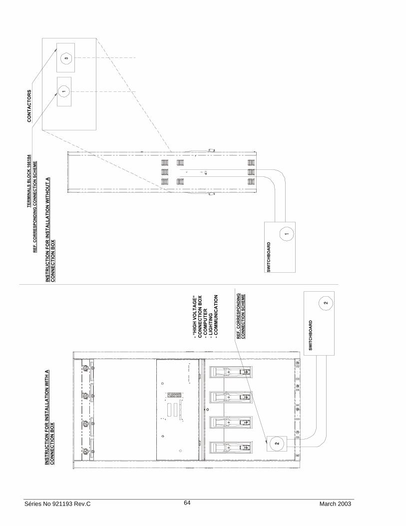
Séries No 921193 Rev.C March 2003 64
INS
TR
UC
TIO
N F
OR
INS
TA
LL
AT
ION
WIT
H A
C
ON
NE
CT
ION
BO
X
INS
TR
UC
TIO
N F
OR
INS
TA
LL
AT
ION
WIT
HO
UT
A
CO
NN
EC
TIO
N B
OX
TE
RM
INA
LS
BL
OC
K 1
6618
4 R
EF
. CO
RR
ES
PO
ND
ING
CO
NN
EC
TIO
N S
CH
EM
E
CO
NT
AC
TO
RS
SW
ITC
HB
OA
RD
- “H
IGH
VO
LT
AG
E“
CO
NN
EC
TIO
N B
OX
-
CO
MP
UT
ER
-
LIG
HT
ING
-
CO
MM
UN
ICA
TIO
N
RE
F. C
OR
RE
SP
ON
DIN
G
CO
NN
EC
TIO
N S
CH
EM
E
SW
ITC
HB
OA
RD

Séries No 921193 Rev.C March 2003 65
9.2 Electrical Installation Scheme 3/G3000P
Drawing 2 Electrical Installation Scheme 3/G3000P – IN 2131 Rev. C
GREEN/YELLOW GREEN/YELLOW
BLACK
BLACK
BLACK
BLACK
BLACK
BLACK
NATURAL
GREEN
BLUE
BLACK
BLUE
BLACK
BLACK
BLACK
110 V MOTOR 4
110 V COMPUTER
110 V LIGHTING
COMMUNICATION
SINGLE-PHASE
MOTOR
MOTOR
MOTOR
MOTOR
MOTOR
MOTOR
MOTOR
COMPUTER
LIGHTING
COMMUNICATION
THREE-PHASE
SINGLE-PHASE
GREEN/YELLOW GREEN/YELLOW
BLACK
BLACK
BLACK
BLACK
BLUE
BLACK
BLUE
GREEN
NATURAL
BLACK
BLACK
BLACK
BLACK
BLACK
BLACK
BLACK
BLACK
BLACK
MOTOR
MOTOR
MOTOR
THREE-PHASE
BLACK
BLACK
BLACK
BLACK
BLACK
BLACK
BLACK
BLACK
BLACK NATURAL
GREEN
BLUE
BLACK
BLUE
BLACK
BLACK
BLACK
BLACK
COMMUNICATION
LIGHTING
COMPUTER
MOTOR
GREEN/YELLOW GREEN/YELLOW
CHECK THAT THE MOTOR IS CONNECTED ACCORDING TO LOCAL VOLTAGE.
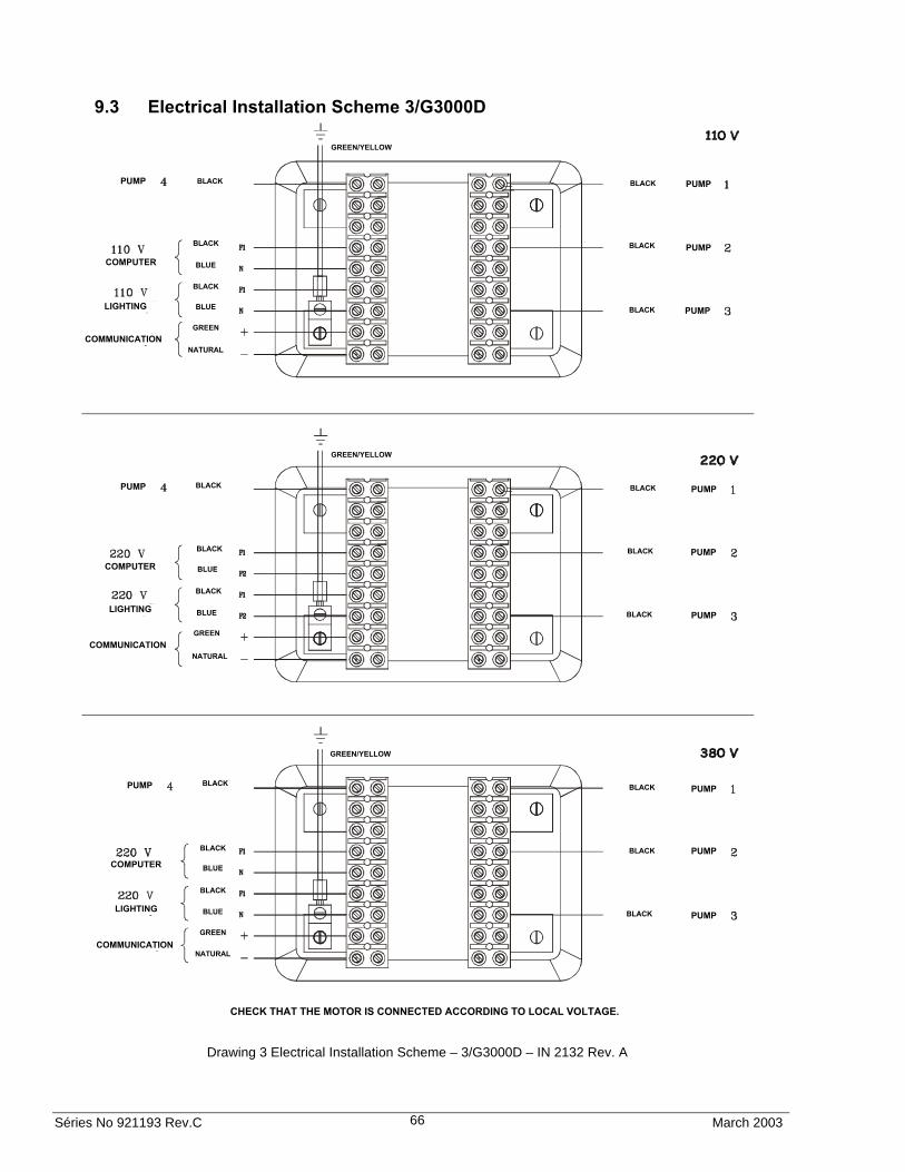
Séries No 921193 Rev.C March 2003 66
9.3 Electrical Installation Scheme 3/G3000D
Drawing 3 Electrical Installation Scheme – 3/G3000D – IN 2132 Rev. A
CHECK THAT THE MOTOR IS CONNECTED ACCORDING TO LOCAL VOLTAGE.
PUMP
PUMP
PUMP PUMP
COMPUTER
LIGHTING
COMMUNICATION
PUMP
PUMP
PUMP
PUMP
COMPUTER
LIGHTING
COMMUNICATION
PUMP
PUMP
PUMP PUMP
COMPUTER
LIGHTING
COMMUNICATION
GREEN/YELLOW
GREEN/YELLOW
GREEN/YELLOW
BLACK
BLACK
BLUE
BLACK
BLUE
GREEN
NATURAL
BLACK
BLACK
BLACK
BLACK
BLACK
BLACK
NATURAL
GREEN
BLUE
BLACK
BLUE
BLACK
BLACK
BLACK
BLACK
BLUE
BLACK
BLUE
GREEN
NATURAL
BLACK
BLACK
BLACK

Séries No 921193 Rev.C March 2003 67
9.4 Installation Instruction of Models 3/G3397P/FC-FP
Drawing 4 – Installation Instruction of Models 3/G3397P/FC-FP – 1-306010 Rev. A
NO
TAS

Séries No 921193 Rev.C March 2003 68
9.5 Installation Instruction of Suction Models
Drawing 5 – Installation Instruction of Suction Models – 1-305532 Rev. D

Séries No 921193 Rev.C March 2003 69
9.6 Installation Instruction of Remote Models
Drawing 6 Installation Instruction of Remote Models – 2-305532 Rev. D

Séries No 921193 Rev.C March 2003 70
9.7 7151-C – Typical Electric Installation Scheme
Drawing 7 Installation Instruction of Suction Models

UL markets:
NOTE: "This equipment has been tested and found to comply with the limits for Class A digital device, pursuant to Part 15 of the FCC Rules. These limits are designed to provide reasonable protection against harmful interference when the equipment is operated in a commercial environment. This equipment generates, uses, and can radiate radio frequency energy and, if not installed and used in accordance with the instruction manual, may cause harmful interference to radio communications. Operation of this equipment in a residential area is likely to cause harmful interference in which case the user will be required to correct the interference at his own expense”.
Dresser Indústria e Comércio Ltda. Division Wayne – Estrada do Timbó, 126 – Bonsucesso CEP: 21061-280 – Rio de Janeiro – RJ – Brasil – Tel.: (21) 2598-7722
March 2003 Séries No 921193 Rev. C