hickman , leonard and broviac catheters · hickman, leonard, and broviac central venous catheters...
TRANSCRIPT

Bard Access Systems
Hickman®, Leonard® andBroviac® Catheters
NURSING PROCEDURE MANUAL
HBLCATHNM/MRKTING 11/30/04 8:25 AM Page 1
Page
Introduction .............................................................................1Description of Catheters and AccessoriesPlacementIndications for UseVitaCuff® Antimicrobial CuffWarnings
Catheter Irrigation Procedure ................................................6Routine Maintenance
Hemodialysis and PlasmapheresisCatheter Irrigation Procedure . ...............................................8
Catheter Irrigation After Blood Aspiration or When Blood is Observed in the Catheter . ..........................10
Blood Withdrawal/Aspiration Procedure . ...........................11
Injection Cap Change Procedure ........................................15
Dressing Change Procedure ...............................................17
Clearing Occluded Catheters Procedure ............................23
Repair Kit / Specifications Table ..........................................26
Broviac® Catheter Repair Procedure....................................28
Hickman® Single-Lumen Catheter andMulti-Lumen Adapter Leg Repair Procedure .......................32
Hickman / Leonard® Multi-Lumen CatheterBody Repair Procedure .........................................................36
Troubleshooting Guide. ........................................................41
I. Aspiration DifficultiesII. Catheter OcclusionIII. Catheter DamageIV. Air in LineV. Fluid Leakage From Catheter Exit Site
Table Of Contents
HBLCATHNM/MRKTING 11/30/04 8:25 AM Page 1

1
Description of Catheters and Accessories
Bard Access Systems Hickman®, Broviac® and Leonard® tun-neled catheters are made of radiopaque medical grade silicone.Each has female luer locking adapter(s) and SureCuff™ TissueIngrowth Cuff for fixation of the catheters in the subcutaneoustunnel.
Each catheter is supplied in a double sterile package. Catheterrepair kits for Hickman, Broviac and Leonard catheters arealso sterile packaged.
Placement
The catheter tip is placed via one of the large central veins intothe superior vena cava above the right atrium. The proximalend of the catheter is tunnelled subcutaneously for several inch-es to the desired exit site. The SureCuff Tissue Ingrowth Cuff,attached to the catheter, is positioned in the tunnel. The cuffhelps secure the catheter through fibrous tissue ingrowth andcreates a physical barrier to help reduce the potential for infec-tion caused by the migration of bacteria through the subcuta-neous tunnel.
ntroductionI
SuperiorVena Cava
Exit Site
Insertion Site
Ventricle
Heart
Atrium
Catheter TipPlacement
Cla
mp
Her
e
HBLCATHNM/MRKTING 11/30/04 8:25 AM Page 2

2
Single-Lumen Features
Adapter Leg
Attached Clamp
VitaCuff®
AntimicobialCuff
SureCuff™ TissueIngrowth Cuff
Cathete
ProtectiveClampingSleeve
Clam
p Here
HBLCATHNM/MRKTING 11/30/04 8:25 AM Page 3
3
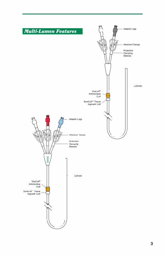
Adapter Legs
Attached Clamps
VitaCuff®
AntimicobialCuff
Catheter
ProtectiveClampingSleeves
Clam
p Here
Clam
p Here
SureCuff™ TissueIngrowth Cuff
Multi-Lumen Features
Adapter Legs
Attached Clamps
VitaCuff®
AntimicobialCuff
ProtectiveClampingSleeves
Clam
p Here
Clam
p Here
Clam
p Here
SureCuff™ TissueIngrowth Cuff
Catheter
HBLCATHNM/MRKTING 11/30/04 8:25 AM Page 4

4
Indications For Use
Hickman, Leonard, and Broviac central venous catheters aredesigned for the administration of I.V. fluids, blood products,drugs and parenteral nutrition solutions, as well as blood with-drawal. Catheters with a VitaCuff Antimicrobial Cuff are intend-ed to help provide protection against catheter related exit siteinfections and sepsis.
VitaCuff® Antimicrobial Cuff
Description
The VitaCuff device is designed to help provide protectionagainst infections related to vascular access catheters. Theouter, tissue-interfacing surface of the VitaCuff device may helpreduce the incidence of infection by incorporating an antimicro-bial agent into the porous collagen matrix.
The VitaCuff device is comprised of two concentric layers ofmaterial.
The internal layer is constructed of speciallyformulated and processed medical grade sil-icone. The external, tissue-interfacinglayer is VitaGuard® antimicrobial colla-gen matrix. The antimicrobial activityof the VitaGuard material is attrib-utable to the silver ions bound tothe collagen matrix. The activ-ity lasts until the VitaGuardmatrix is completely absorbedby the tissue in four to six weeks.The VitaGuard collagen sponge isinitially in a compressed state for easeof insertion. After placement, the matrixabsorbs physiological fluids, quickly expandsto approximately twice its original size, and helps provide anantimicrobial barrier and a physical barrier at the exit site.
HBLCATHNM/MRKTING 11/30/04 8:25 AM Page 5

Tissue ingrowth into the VitaGuard collagen matrix occurs in afew days, further securing the catheter in place, and reducingcatheter movement.
CAUTION: The antimicrobial cuff is not intended to be used asa treatment for catheter related infections. The antimicrobial cuffdoes not provide protection against “blood seeding” infection orinfusate-related infection. It is not intended to provide protectionfrom bacteria for longer than one month. The antimicrobial cuffshould not be used on patients with known sensitivities to silverions or collagen.
Warnings
Infusion pressures should never exceed 25 psi. Smallersyringes generate more pressure than larger syringes. A twopound weight equivalent force on the barrel of a 3 cc syringegenerates pressure in excess of 25 psi. The same two poundweight equivalent force on the barrel of a 10cc syringe gener-ates less than 8 psi of pressure. It is recommended that nosmaller than a 10cc syringe be used for infusion into aHickman, Leonard, or Broviac catheter.
When catheter damage or connector separation occurs, thecatheter should be immediately clamped or kinked closed to pre-vent any possibility of air embolism or loss of blood.
Universal precautions should be observed by all health care pro-fessionals when performing the procedures included in this man-ual.
5
Exit Site
VitaCuff®
AntimicrobialCuff
SureCuff™
TissueIngrowth Cuff
HBLCATHNM/MRKTING 11/30/04 8:25 AM Page 6

6
C atheter Irrigation ProcedurePurpose
To maintain catheter patency.
Routine Maintenance
Flushing frequencies from once daily to once weekly have beenfound to be effective when the catheter is not in use. Flush withheparin after IV administration of TPN, IV fluids, or after medica-tions. NOTE: For frequently accessed catheters (accessed atleast every 8 hours), flushing with 5cc of normal saline withoutheparin between infusions has been found to be effective.
Supplies
• Isopropyl alcohol and/or povidone-iodine wipes• 10cc syringe with attached 1 in. needle, filled with 2.5cc of
heparinized saline, or 5cc normal saline (Using a 10ccsyringe reduces pressure during flushing and reduceschances of rupturing the catheter due to over pressuriza-tion.)
NOTE: The appropriate heparin concentration, volume, andflushing frequency should be based on the patient’s medicalcondition, laboratory tests, and prior clinical experience.Heparin concentrations of 10 u/ml - 1,000 u/ml have been foundto be effective.
HBLCATHNM/MRKTING 11/30/04 8:25 AM Page 7

7
Procedure
Hickman and Leonard Catheters:
1. Clean injection cap with alcohol and/or povidone-iodinewipe.
2. Insert needle of 10cc syringe containing 5cc normal salineor 2.5cc heparinized saline into injection cap.
3. Release clamp.
4. Inject irrigation solution, withdrawing needle from injectioncap as last 1/2 cc of solution is infused (Helps prevent a vac-uum which can pull a small amount of blood into cathetertip).
5. Close catheter clamp if indicated by hospital procedure.
Broviac Catheters:
Follow the above procedure except use 2cc normal saline or1.5cc heparinized saline.
CAUTION: Always use a 10cc or larger syringe and flush slowlyto avoid rupturing the catheter.
HBLCATHNM/MRKTING 11/30/04 8:25 AM Page 8

Purpose
To maintain catheter patency.
Routine Maintenance
Prior to initiation of therapy or reinstallation of fresh heparinizedsaline, the indwelling heparin should be aspirated from thecatheter and the lumen(s) flushed with 10cc sterile normalsaline. Flush with 10cc sterile normal saline and then heparinafter completion of therapy.
Supplies
• Isopropyl alcohol and/or povidone-iodine wipes• 10cc syringe with attached 1 in. needle, filled with 10cc
normal saline• 10cc syringe with attached 1 in. needle, filled with
catheter priming volume of heparinized saline
NOTE: The appropriate heparin concentration and flushing fre-quency should be based on the duration of the interdialytic peri-od, patient’s medical condition, laboratory tests, and prior expe-rience. Heparin concentrations of 1000-5000 USP units/ml havebeen found to be effective for maintaining the patency hemodial-ysis and plasmapheresis catheters.
8
H emodialysis and PlasmapheresisCatheter Irrigation Procedure
HBLCATHNM/MRKTING 11/30/04 8:25 AM Page 9

Procedure
1. Wash hands thoroughly.
2. Clean injection cap with alcohol and/or povidone-iodinewipe.
3. Insert needle of saline-filled 10cc syringe into injection cap.
4. Release clamp.
5. Inject normal saline into catheter and remove needle frominjection cap.
6. Clean injection cap with alcohol and/or povidone-iodinewipe.
7. Insert needle of heparin-filled 10 cc syringe into injectioncap.
8. Release clamp.
9. Inject irrigation solution, withdrawing needle from injectioncap as last 0.5cc of solution is infused (helps prevent a vac-uum which can pull a small amount of blood into cathetertip).
10. Close catheter clamp, if indicated by hospital procedure.
9
HBLCATHNM/MRKTING 11/30/04 8:25 AM Page 10

10
C atheter Irrigation After BloodAspiration or When Blood is Observedin the Catheter
Supplies
• Isopropyl alcohol and/or povidone-iodine wipes• 10cc syringe with attached 1 in. needle containing
10cc normal saline.• 10cc syringe with attached 1 in. needle containing 2.5cc
heparinized saline (if catheter is to be heparin-locked).
Procedure
Hickman and Leonard Catheters:
1. Follow Routine Maintenance Procedure, except use 10ccnormal saline to clear blood from the catheter, followed by2.5cc heparinized saline to heparin lock the catheter.
2. If unable to flush all blood residue out of the injection cap,replace it after blood sampling per Injection Cap ChangeProcedure (per hospital policy).
Broviac Catheters:
Follow above procedure except use 3cc normal saline, followedby 1.5cc heparinized saline. The injection cap may need to bechanged because blood cannot be flushed entirely out of capwith this amount of fluid.
HBLCATHNM/MRKTING 11/30/04 8:25 AM Page 11

Purpose
To obtain blood samples for laboratory evaluation, withoutperipheral venipunctures.
To verify venous placement prior to administration of hypertonicor vesicant solutions.
NOTE: While smaller lumen Broviac catheters have been usedsuccessfully for blood withdrawal, their small lumen sizesincrease the chance of clotting. The larger Hickman single-lumen catheter is intended for both infusion of I.V. fluids, med-ications, and nutritional solutions, and for withdrawal of bloodsamples.
Hub-To-Hub Technique (syringe)
Supplies
• 4 - 10cc syringes• 1 - 1 in. needle• 0.9% Sodium Chloride (normal saline)• Heparinized saline (10u - 1000u/ml. per hospital policy)• Isopropyl alcohol wipes/povidone-iodine wipes• Blood specimen tubes
Procedure
1. Wash hands thoroughly.
2. Draw 10cc of normal saline into one 10cc syringe and 2.5ccheparinized saline into another 10cc syringe and set aside.
3. Apply smooth-edged atraumatic clamp to silicone clampingsleeve.
11
B lood Withdrawal / Aspiration Procedure
HBLCATHNM/MRKTING 11/30/04 8:25 AM Page 12

4. Stop any IV fluids infusing through the catheter, includinganother lumen of the catheter. Remove injection cap/I.V.tubing from catheter hub.
5. Clean catheter hub with alcohol and/or povidone-iodinewipe.
6. Attach an empty 10cc syringe to catheter hub.
7. Open clamp.
8. Aspirate 5cc of blood.
9. Re-clamp catheter.
10. Disconnect syringe and discard (saline or heparin incatheter dilutes specimen and may alter lab values).
11. Attach an empty 10cc syringe, open clamp, and aspiratesample.
12. Re-clamp catheter.
13. Disconnect syringe and attach saline-filled syringe.
14. Open clamp.
15. Flush the catheter with 10cc normal saline.
16. Re-clamp catheter.
17. Attach heparin-filled syringe.
18. Open clamp.
19. Flush the catheter with 2.5cc heparinized saline.
20. Re-clamp catheter.
21. Disconnect syringe and clean catheter hub with alcoholand/or povidone-iodine wipe.
22. Attach new injection cap per Injection Cap Change Procedureor attach sterile I.V. tubing to hub of catheter.
23. Attach 1 in. needle to blood sample syringe to transfer toblood collection tubes.
NOTE: If you encounter difficulties with blood withdrawal, seeTroubleshooting Guide - Aspiration Difficulties.
12
HBLCATHNM/MRKTING 11/30/04 8:25 AM Page 13
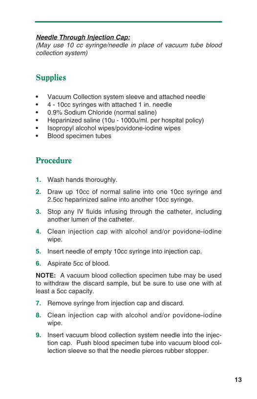
Needle Through Injection Cap:(May use 10 cc syringe/needle in place of vacuum tube bloodcollection system)
Supplies
• Vacuum Collection system sleeve and attached needle• 4 - 10cc syringes with attached 1 in. needle• 0.9% Sodium Chloride (normal saline)• Heparinized saline (10u - 1000u/ml. per hospital policy)• Isopropyl alcohol wipes/povidone-iodine wipes• Blood specimen tubes
Procedure
1. Wash hands thoroughly.
2. Draw up 10cc of normal saline into one 10cc syringe and2.5cc heparinized saline into another 10cc syringe.
3. Stop any IV fluids infusing through the catheter, includinganother lumen of the catheter.
4. Clean injection cap with alcohol and/or povidone-iodinewipe.
5. Insert needle of empty 10cc syringe into injection cap.
6. Aspirate 5cc of blood.
NOTE: A vacuum blood collection specimen tube may be usedto withdraw the discard sample, but be sure to use one with atleast a 5cc capacity.
7. Remove syringe from injection cap and discard.
8. Clean injection cap with alcohol and/or povidone-iodinewipe.
9. Insert vacuum blood collection system needle into the injec-tion cap. Push blood specimen tube into vacuum blood col-lection sleeve so that the needle pierces rubber stopper.
13
HBLCATHNM/MRKTING 11/30/04 8:25 AM Page 14

10. Blood needed for specimen will flow into specimen tube.Change tubes as needed for required tests.
11. Remove vacuum blood collection system needle and sleevefrom injection cap.
12. Clean injection cap with alcohol and/or povidone-iodinewipe.
13. Insert needle of saline-filled syringe and flush the catheterwith 10cc of normal saline.
14. Clean injection cap with alcohol and/or povidone-iodinewipe.
15. If unable to flush all of the blood residue out of the injectioncap, attach a new sterile injection cap per Injection CapChange Procedure (or hospital policy).
16. Insert needle of heparin-filled syringe and flush the catheterwith 2.5cc heparinized saline.
NOTE: If you encounter difficulties with blood withdrawal, seeTroubleshooting Guide - Aspiration Difficulties.
14
HBLCATHNM/MRKTING 11/30/04 8:25 AM Page 15
15
Purpose
To minimize potential for infection from overuse and leakage ofinjection cap.
Frequency
- Every seven days, 18 needle insertions, or per hospitalpolicy.
- When the cap has been removed for any reason.
- Anytime the cap appears damaged, is leaking, blood is seenin the catheter without explanation, or blood residue isobserved in the cap.
- After blood withdrawal through the injection cap (per hospi-tal policy).
Supplies
• New sterile injection cap• Alcohol wipes• Tape• 10cc syringe with attached 1 in. needle filled with 2.5cc
heparinized saline (10u - 1000u/ml. per hospital policy) or5cc normal saline.
Procedure
1. Wash hands.
I njection Cap Change
HBLCATHNM/MRKTING 11/30/04 8:25 AM Page 16

2. Using aseptic technique, open sterile injection cap packageand pre-fill injection cap with heparinized saline, or normalsaline.
3. Apply smooth-edged atraumatic clamp to silicone clampingsleeve and remove the old injection cap.
4. Clean the outside of the catheter hub with an alcohol wipeand/or povidone-iodine wipe.
5. Remove the tip protector from the new injection cap andtwist the cap clockwise onto the catheter hub.
6. Irrigate the catheter with 2.5cc heparinized saline, or 5ccnormal saline following the Catheter Irrigation Procedure(per hospital policy).
7. Tape the connection (per hospital policy).
16
HBLCATHNM/MRKTING 11/30/04 8:25 AM Page 17

Purpose
To prevent infection of the central venous catheter.
Frequency
- Gauze and tape dressing - M, W, F, and prn if soiled, damp,or loosened.
- Transparent dressing - every 7 days and prn if loosened.
NOTE: If granulocyte count less than 200/mm, you may wish toconsider changing the dressing daily.
Gauze and Tape Dressing
(Long-term catheters: recommended for first 1-2 weeks afterplacement until the cuff is healed in due to exit site exudate dur-ing healing process)
Supplies
• Sterile dressing kit which includes:• 3 - 70% Isopropyl alcohol swabsticks or hydrogen peroxide
and sterile cotton-tipped applicators.• 3 - Povidone-iodine swabsticks• 1 - Packet povidone-iodine ointment (optional)• 1 - 2 in. x 2 in. split gauze• 1 - 2 in. x 2 in. gauze• 1 - Protective dressing wipe or swabstick (optional)• 2 - Isopropyl alcohol wipes• 1 Pr. - Sterile gloves (recommended if dressing is changed
in a health care facility due to universal precautions andincreased risk of cross-contamination)
17
D ressing Change Procedure
HBLCATHNM/MRKTING 11/30/04 8:25 AM Page 18

Procedure
1. Wash hands thoroughly.
2. Carefully remove old dressing and discard. Avoid tuggingon the catheter, or the use of scissors, or other sharpobjects near the catheter.
3. Inspect catheter exit site for swelling, redness, or exudate.Notify physician if problem is observed.
4. Wash hands thoroughly.
5. Put on sterile gloves.
6. Clean the catheter exit site with an alcohol swabstick orhydrogen peroxide-soaked cotton-tipped applicator, startingat the exit site and spiraling outward until a circle at least 3inches in diameter has been covered. Do not return to thecatheter exit site with the same swabstick/applicator.Repeat with the remaining 2 swabsticks/applicators.
7. Clean the catheter exit site with a povidone-iodine swab-stick, starting at the exit site and spiraling outward until a cir-cle at least 3 inches in diameter has been covered. Do notreturn to the catheter exit site with the same swabstick.Repeat with the remaining 2 swabsticks.
8. Allow povidone-iodine to dry at least 2 minutes.
9. Gently clean the outside of the catheter with the inside sur-face of an alcohol wipe, starting from the exit site to thecatheter hub. Prevent pulling on the catheter by holdingthe catheter at the exit site with one alcohol wipe andcleaning with another alcohol wipe.
10. Apply a small amount of povidone-iodine ointment to thecatheter exit site (optional).
11. Apply a split 2 in. x 2 in. gauze over the catheter exit site.
12. Top with a 2 in. x 2 in. gauze.
13. If a protective dressing wipe or swabstick is used, apply it tothe skin to be taped around the periphery of the gauze andallow to dry completely.
18
HBLCATHNM/MRKTING 11/30/04 8:25 AM Page 19

14. Cover gauze and 1 in. of surrounding skin with tape.
15. Loop catheter tubing and tape it securely to dressing or skin(prevents pulling on the catheter).
Transparent Dressing
Supplies
• 3 - Alcohol swabsticks or hydrogen-peroxide and sterile cotton-tipped applicators
• 3 - Povidone-iodine swabsticks• 1 - Packet povidone-iodine ointment (optional)• 1 - Transparent dressing• 2 - Isopropyl alcohol wipes• 1 Pr. - Sterile gloves (recommended if dressing is changed
in a health care facility due to universal precautions andincreased risk of cross-contamination)
• 1 - 2 in. x 2 in. or 4 in. x 4 in. sterile gauze
Procedure
1. Wash hands thoroughly.
2. Carefully remove old dressing and discard. Avoid tuggingon the catheter, or the use of scissors, or other sharpobjects near the catheter.
3. Inspect catheter exit site for swelling, redness, or exudate.Notify physician if problem observed.
4. Wash hands thoroughly.
5. Put on sterile gloves.
6. Clean the catheter exit site with an alcohol swabstick orhydrogen peroxide soaked cotton-tipped applicator, startingat the exit site and spiraling outward until a circle at least 3inches in diameter has been prepped. Do not return to thecatheter exit site with the same swabstick/applicator.Repeat with the remaining 2 swabsticks/applicators.
19
HBLCATHNM/MRKTING 11/30/04 8:25 AM Page 20

7. Clean the catheter exit site with a povidone-iodine swab-stick, starting at the exit site and spiraling outward until a cir-cle at least 3 inches in diameter has been covered. Do notreturn to the catheter exit site with the same swabstick.Repeat with the remaining 2 swabsticks.
8. Allow povidone-iodine to dry at least 2 minutes.
9. Gently clean the outside of the catheter with the inside sur-face of an alcohol wipe, starting from the exit site to thecatheter hub. Avoid pulling on the catheter by holding thecatheter at the exit site with one alcohol wipe and cleaningwith another alcohol wipe.
10. Pat the exit site with sterile gauze to remove any excesspovidone-iodine.
11. Apply a small amount of povidone-iodine ointment to thecatheter exit site (optional).
12. Apply the transparent dressing by centering it over thecatheter exit site.
13. Loop the catheter tubing and tape it securely to the skin(Prevents pulling on the catheter).
20
HBLCATHNM/MRKTING 11/30/04 8:25 AM Page 21

Broviac Catheters
Try to secure catheter out of sight for infants and children by:
- Tunneling catheter to lateral back exit site.
- Using vests and other clothing to completely cover tubingand exit site.
Do not allow child to chew or pull on tubing at any time to avoidcatheter damage or breakage.
References
Jarrard, MM, Olsen, CM, Freeman, JB, “Daily Dressing ChangeEffects On Skin Flora Beneath Subclavian Catheter DressingsDuring Total Parenteral Nutrition”, Journal of Parenteral andEnteral Nutrition, Vol. 4, No. 4, 1980, pp. 391-392.
Murphy, LM, Lipman, TO, “Central Venous Catheter Care inParenteral Nutrition: A Review”, Journal of Parenteral & EnteralNutrition, Vol. II, No. 2, 1987, pp. 190-201.
Nehme, AE, Trigger, JA “Catheter Dressings in Central VenousParenteral Nutrition: A Prospective Randomized ComparativeStudy”, Nutritional Support Services, Vol. 4, 1984, pp.42-50.
Palidar, PJ, Siminowitz, DA, Oreskovich, MR, “Use of OpSite asan Occlusive Dressing for Total Parenteral Nutrition Catheters”,Journal of Parenteral & Enteral Nutrition, Vol. 6, No. 2, 1982, pp.150-151.
Powell, C., Regan, C., Fabri, PJ, et al, “Evaluation of OpSiteCatheter Dressings for Parenteral Nutrition: A ProspectiveRandomized Study”, Journal of Parenteral & Enteral Nutrition,Vol. 6, No. 1, 1982, pp. 43-46.
Schwartz, Fulton, J., Colley, R., Valanis, B., et al,“Hyperalimentation Dressings & Skin Flora”, NITA, Vol. 4, 1981,pp. 354-357.
21
HBLCATHNM/MRKTING 11/30/04 8:25 AM Page 22

Vasquez, RM, Jarrard, MM, “Care of the Central VenousCatheterization Site: The Use of a Transparent PolyurethaneFilm”, Journal of Parenteral & Enteral Nutrition, Vol. 8, No. 2,1984, pp. 181-186.
Petrosino, B, Becker, H, Christian, B, “Infection Rates in CentralVenous Catheter Dressings”, Oncology Nursing Forum, Vol. 15,No. 6, 1988, pp. 709-717.
Shevnan, JC, McGuire, D, Freedman, S. et al, “A Comparison ofTransparent Adherent and Dry Sterile Gauze Dressings forLong-Term Central Catheters in Patients Undergoing BoneMarrow Transplant”, Oncology Nursing Forum, Vol. 18, No. 8,1991, pp. 1349-1356.
22
HBLCATHNM/MRKTING 11/30/04 8:25 AM Page 23

Purpose
To restore patency to a catheter with an occlusion.
Supplies
• 1 - Sterile injection cap• 5,000 IU/cc urokinase (catheter priming volume)• 1 - 10cc syringe with attached 1 in. needle • 1 - 10cc sterile normal saline-filled syringe with attached
1 in. needle• Isopropyl alcohol wipes
Procedure
1. Wash hands.
2. Apply smooth-edged atraumatic clamp to silicone clampingsleeve.
3. Remove injection cap, attach an empty 10cc syringe,release clamp, and attempt to aspirate. If aspiration is suc-cessful, withdraw clots, clamp catheter, and attach saline-filled syringe. Release clamp and flush catheter with 10 ml.normal saline. Clamp catheter. Replace cap per InjectionCap Change Procedure. If aspiration is unsuccessful, pro-ceed to step 4.
4. Obtain physician’s order for the use of urokinase 5,000 IU/ccto declot the catheter.
5. Draw up enough urokinase 5,000 IU/cc into a 10cc syringeto equal the internal volume of the catheter (volume may bereduced if catheter length has been cut). SeeHickman/Leonard /Broviac Catheter Repair Kit /Specifications Table for catheter priming volumes.
23
C learing Occluded Catheters
HBLCATHNM/MRKTING 11/30/04 8:25 AM Page 24

6. Aseptically attach the urokinase-filled syringe to the catheterhub. Release clamp and slowly and gently inject the uroki-nase solution into the catheter. To avoid catheter rupture,do not force entire amount into catheter.
7. Leave 10cc syringe attached to catheter. Do not attempt toaspirate for 30-60 minutes.
8. After 30-60 minutes, attempt to aspirate the drug and resid-ual clot. If unsuccessful, repeat urokinase instillation.
9. When patency is restored, aspirate 5cc of blood to assureremoval of all drug and clots.
10. Clamp catheter, remove blood-filled syringe, and replace itwith a 10cc syringe filled with normal saline. Open clampand flush catheter to verify patency.
11. Clamp catheter and remove syringe.
12. Attach sterile heparin-filled injection cap and flush catheterwith heparin per Catheter Irrigation Procedure.
NOTE:
If infusing:
- TPN and lipid solutions, and urokinase does not clear theblockage, an ethanol 70% solution may be instilled and leftin place for 1 hour. Follow procedure for urokinase instilla-tion. This may help to clear the catheter of lipid materialdeposition.
- TPN or calcium and phosphate IV solutions or other medica-tions which might leave a precipitate, and urokinase doesnot clear blockage, a sterile 0.1 N Hydrochloric Acid solutionmay be instilled in the catheter and left in place for one hour.The solution is then aspirated and the catheter flushed withnormal saline. This may help to clear the catheter of calci-um-phosphate or other drug precipitates. Sodium bicarbon-ate may also be used for precipitates that are soluble in abasic solution.
24
HBLCATHNM/MRKTING 11/30/04 8:25 AM Page 25

REFERENCES:
Bjeletich, J., “Declotting Central Venous Catheters withUrokinase in the Home by Nurse Clinicians”, NITA, Nov/Dec1987, pp. 428-430.
Faubion, WC, Bollish, SJ, Wesley, JR, “Central Venous CatheterOcclusion Treated by Thrombolytic Agents”, Nutritional SupportServices, Vol. 3, No. 2, 1983, pp. 24-26.
Gale, GB, O’Connor, DM, Chu, J-Y, Stanley, D., “RestoringPatency of Thrombosed Catheters with CryopreservedUrokinase”, Journal of Parenteral & Enteral Nutrition, Vol. 8, No.3, 1984, pp. 298-299.
Murphy, LM, Lipman, TO, “Central Venous Catheter Care inParenteral Nutrition: A Review”, Journal of Parenteral & EnteralNutrition, Vol. 11, No. 2, 1987, pp. 190-201.
Pennington, CR, Pithic, AD, “Ethanol Lock in the Managementof Catheter Occlusion”, Journal of Parenteral & Enteral Nutrition,Vol. 11, No. 5, 1987, pp. 507-508.
Shulman, RJ, Reed, T., Pitre, D., Laine, L., “Use of HydrochloricAcid to Clear Obstructed Central Venous Catheters,” Journal ofParenteral & Enteral Nutrition, Vol. 12, No. 6, 1988,pp. 509-510.
Holcombe, BJ, Forloines-Lynn, S, Garmhausen, LW, “RestoringPatency of Long-Term Central Venous Access Devices”, Journalof Intravenous Nursing, Vol. 15, No. 1, January/February 1992,pp.36-41.
25
HBLCATHNM/MRKTING 11/30/04 8:25 AM Page 26

Repair Kit / Specifications Table (part I)
26
Catheter Description Repair Kit # Temporary TotalRepair Length
Repair Kit # Description
0601600
0601610
0601620
0601620
0601630
0601650
0601670
24 Ga.
22 Ga.
20 Ga.
20 Ga.
16 Ga.
N/A
N/A
16 Ga. (Legs)
16 Ga. (Legs)
16 Ga. (Legs)
16 Ga. (Legs)
16 Ga. (Legs)
N/A
N/A
N/A
71cm
71cm
90 cm
90 cm
90 cm
30 cm
26 cm
Single-Lumen
Dual-Lumen
Triple-Lumen
Adhesive
Broviac 2.7 Fr.
Broviac 4.2 Fr.
Broviac 6.6 Fr.
Broviac 6.6 Fr. Short Length
Hickman 9.6 Fr.
Hickman 10.8 Fr. Pheresis / Dialysis
Hickman 14.4 Fr. Pheresis / Dialysis
0601680 - White ext.0601690 - Red ext.0601760 - Body
0601680 - White ext.0601690 - Red ext.0601700 - Body
0601680 - White ext.0601690 - Red ext.0601700 - Body
0601680 - White ext.0601690 - Red ext.0601750 - Body
0601680 - White ext.0601690 - Red ext.0601710 - Body
0601770 - Blue ext.0601780 - Red ext.
0601770 - Blue Leg0601780 - Red Leg
0601770 - Blue Leg0601780 - Red Leg
65 cm
65 cm
90 cm
90 cm
90 cm
36 cm
28 cm
40 cm
Hickman 7.0 Fr.
Hickman 9.0 Fr. Pediatric
Hickman 9.0 Fr.
Leonard 10.0 Fr.
Hickman 12.0 Fr.
Hickman 13.5 Fr.
Hickman 13.5 Fr. Pheresis / Dialysis
Hickman 13.5 Fr. Pheresis / Dialysis
16 Ga. (Legs)
16 Ga. (Legs)
0601680 - White ext.0601690 - Red ext.0601730 - Blue ext.0601790 - Body
0601680 - White ext.0601690 - Red ext.0601730 - Blue ext.0601740 - Body
90 cm
90 cm
Hickman 10.0 Fr.
Hickman 12.5 Fr.
Adhesive Repair Kit 0601720Silicone Adhesive for CatheterRepair (Does not contain cathetercomponents)
HBLCATHNM/MRKTING 11/30/04 8:25 AM Page 27

27
Repair Kit / Specifications Table (part II)
Catheter Description Volume O.D. / I.D.
0.9 / 0.5 mm
1.4 / 0.7 mm
2.2 / 1.0 mm
2.2 / 1.0 mm
3.2 / 1.6 mm
3.6 / 2.0 mm
4.8 / 2.6 mm
2.3 / 0.8 mm - White1.0 mm - Red
3.0 / 0.7 mm - White1.3 mm - Red
3.0 / 0.7 mm - White1.3 mm - Red
3.3 / 1.3 mm - White1.3 mm - Red
4.0 / 1.6 mm - White1.6 mm - Red
4.5 / 2.0 mm - Blue2.0 mm - Red
4.5 / 2.0 mm - Blue2.0 mm - Red
4.5 / 2.0 mm - Blue2.0 mm - Red
3.3 / 0.8 mm - White0.8 mm - Blue1.5 mm - Red
4.2 / 1.0 mm - White1.0 mm - Blue1.5 mm - Red
Single-Lumen
Dual-Lumen
Triple-Lumen
Broviac 2.7 Fr.
Broviac 4.2 Fr.
Broviac 6.6 Fr.
Broviac 6.6 Fr. Short Length
Hickman 9.6 Fr.
Hickman 10.8 Fr. Pheresis / Dialysis
Hickman 14.4 Fr. Pheresis / Dialysis
Hickman 7.0 Fr.
Hickman 9.0 Fr. Pediatric
Hickman 9.0 Fr.
Leonard 10.0 Fr.
Hickman 12.0 Fr.
Hickman 13.5 Fr.
Hickman 13.5 Fr. Pheresis / Dialysis
Hickman 13.5 Fr. Pheresis / Dialysis
Hickman 10.0 Fr.
Hickman 12.5 Fr.
0.15 cc
0.3 cc
0.7 cc
0.7 cc
1.8 cc
0.9 cc
1.4 cc
0.6 cc.- White0.8 cc - Red
0.6 cc.- White1.3 cc - Red
0.6 cc.- White1.3 cc - Red
1.3 cc.- White1.3 cc - Red
1.8 cc.- White1.8 cc - Red
1.4 cc.- Blue1.3 cc - Red
1.0 cc.- Blue1.0 cc - Red
1.4 cc.- Blue1.4 cc - Red
0.8 cc.- White0.8 cc.- Blue1.4 cc - Red
0.7 cc.- White0.7 cc.- Blue1.6 cc - Red
HBLCATHNM/MRKTING 11/30/04 8:25 AM Page 28

Purpose
To repair the damaged external segment of a Broviac catheterif there is at least 3 cm. of undamaged catheter remaining.
NOTE: Catheter should have been clamped with atraumaticclamp between catheter exit site and damaged area when dam-age occurred and must remain clamped during repair.
Repair Kit Contents
• Silicone External Replacement Catheter Segment• Silicone Splicing Sleeve (Shipped Loose-Mounted on
Replacement Segment).• Splice Connector Stent (Mounted on Replacement
Segment).• Injection Cap• Clamp• Tube of Medical Adhesive• Disposable Plastic Syringe• Blunt 18 Ga. Needle• Instructions
Additional Supplies Needed:
AlcoholAntiseptic (Povidone-Iodine is Recommended)Atraumatic Clamp and ForcepsSterile Drapes4 in. x 4 in. Gauze SpongesHeparin (Volume & Concentration per Hospital Policy)Sterile Scalpel or Scissors
28
B roviac® CatheterRepair Procedure
HBLCATHNM/MRKTING 11/30/04 8:25 AM Page 29

Sterile Gloves10cc SyringeTapeTongue Blade or Application Sticks
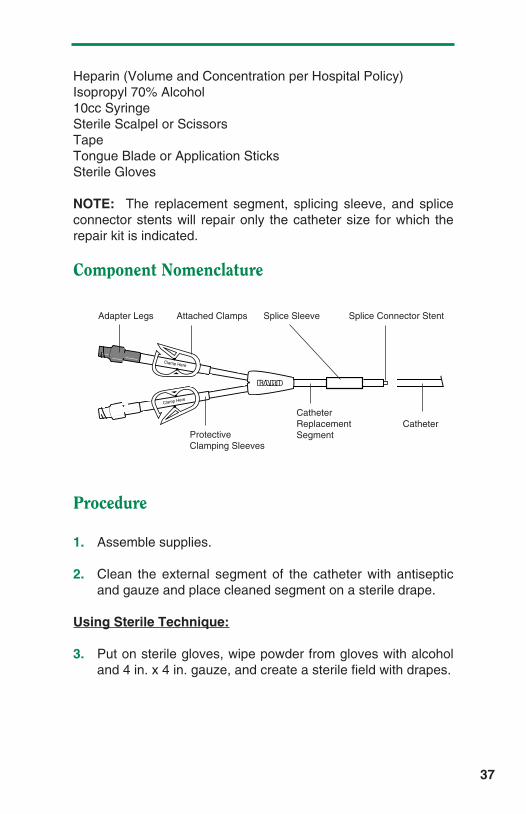
NOTE: The replacement segment, splicing sleeve, and spliceconnector stents will repair only the catheter size for which therepair kit is indicated.
Component Nomenclature
1. Assemble supplies.
2. Clean the external segment of the catheter with antisepticand gauze and place cleaned segment on a sterile drape.Do not pull on catheter while cleaning.
Using Sterile Technique:
3. Put on sterile gloves, wipe powder from gloves with alcoholand 4 in. x 4 in. gauze, and create a sterile field with drapes.
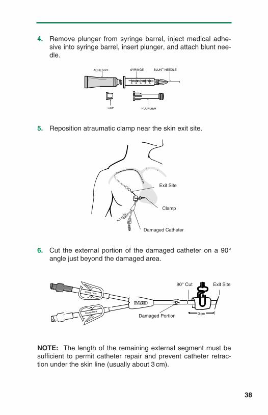
4. Remove plunger from syringe barrel, inject medical adhe-sive into syringe barrel, insert plunger, and attach blunt nee-dle.
29
Adapter Leg Attached Clamp Splice Sleeve Splice Connector Stent
Protective Clamping SleeveCatheterReplacement Segment
InnerLumen
Catheter
Clamp Here
12345
ADHESIVE
PLUNGERCAP
SYRINGE BLUNT NEEDLE
HBLCATHNM/MRKTING 11/30/04 8:25 AM Page 30

5. Reposition atraumatic clamp near the skin exit site.
6. Cut the external portion of the damaged catheter at a 90°angle just distal to the damaged area.
NOTE: The length of the remaining external segment must besufficient to permit catheter repair and prevent catheter retrac-tion under the skin line. If the inner lumen of the catheterretracts inside the outer sheath, the outer sheath should be cutoff flush with the inner lumen.
7. Pull inner tubing from outer sheath 1 cm with atraumatic for-ceps. Insert the splice connector (stent) into the inner lumenuntil catheter segments are together. Lubricate withIsopropyl 70% alcohol if necessary, but be sure the alcoholis removed or evaporated before proceeding.
30
Damaged Catheter
90° Cut
Clamp
Inner Tubing
Outer Sheath
1 cm
Exit Site
Exit Site
Clamp H
ere
HBLCATHNM/MRKTING 11/30/04 8:25 AM Page 31

8. Use syringe to apply adhesive onto the exposed inner lumenand ease outer sheath over it. Roll between fingers to even-ly distribute the adhesive and wipe away excessive adhe-sive.
9. Use syringe again to apply adhesive onto the outside of thecatheter around the spliced joint. Slide the splicing sleevedown and center it over the joint. Inject adhesive under-neath each end of the splicing sleeve. Roll the splicingsleeve between fingers to distribute and extrude excessadhesive. Wipe away excess adhesive.
Sterile Field Is No Longer Required
10. Remove clamp and GENTLY fill catheter with heparin.CAUTION: Excessive pressure may rupture joint.
11. Fasten catheter repair joint to splint (application sticks ortongue blade) with tape.
NOTE: If necessary, the catheter may be used for infusion afterfour hours. The joint will not achieve full mechanical strength for48 hours. The splint may be removed at that time.
1
�
���
��
��
����
���
�
���
���
��
1
2
1
2
3
4
5
��
���
���
��
31
Splice Sleeve Adhesive
HBLCATHNM/MRKTING 11/30/04 8:25 AM Page 32

Purpose
To repair the damaged external segment of a single-lumenHickman catheter if there is at least 3 cm. of undamagedcatheter remaining beyond the skin exit site, or 3 cm. remainingon the adapter leg of a multi-lumen catheter.
NOTE: Catheter should have been clamped with atraumaticclamp between the catheter exit site and the damaged areawhen damage occurred and must remain clamped during repair.
Repair Kit Contents
• Silicone External Replacement Catheter Segment• Silicone Splicing Sleeve (Shipped Loose-Mounted on
Replacement Segment)• Splice Connector Stent (Mounted on Replacement
Segment)• Injection Cap• Clamp• Tube of Medical Adhesive• Disposable Plastic Syringe• Blunt 18 Ga. Needle• Instructions
Additional Supplies Needed
Antiseptic (Povidone-Iodine is Recommended)Atraumatic ClampSterile Drapes
32
H ickman® Single-LumenCatheter and Multi-LumenAdapter Leg Repair Procedure
HBLCATHNM/MRKTING 11/30/04 8:25 AM Page 33

4 in. x 4 in. Gauze SpongesHeparin (Volume and Concentration per Hospital Policy)Isopropyl 70% AlcoholSterile Scalpel or ScissorsSterile Gloves10cc SyringeTapeTongue Blade or Application Sticks
NOTE: The replacement segment, splicing sleeve, and spliceconnector stents will repair only the catheter size for which therepair kit is indicated.
Component Nomenclature
1. Assemble supplies.
2. Clean the external segment of the catheter with antisepticand gauze and place cleaned segment on a sterile drape.
Using Sterile Technique:
3. Put on sterile gloves, wipe powder from gloves with alcoholand 4 in. x 4 in. gauze, and create a sterile field with drapes.
4. Remove plunger from syringe barrel, inject medical adhe-sive into syringe barrel, insert plunger, and attach blunt nee-dle.
33
Clamp Here
Adapter Leg Attached Clamp Splice Sleeve Splice Connector Stent
Protective Clamping SleeveCatheterReplacement Segment
Catheter
12345
ADHESIVE
PLUNGERCAP
SYRINGE BLUNT NEEDLE
HBLCATHNM/MRKTING 11/30/04 8:25 AM Page 34

5. Reposition atraumatic clamp near the skin exit site.
6. Cut the external portion of the damaged catheter at a 90°angle just distal to the damaged area.
NOTE: The length of the remaining external segment mustbe sufficient to permit catheter repair and prevent catheterretraction under the skin line.
7. Insert the splice connector stent attached to the replacementcatheter segment into the catheter lumen until the end of thereplacement catheter tubing is 1/8 in. from the cut end of thecatheter.
8. Dry space between catheter ends with a sterile 4 in. x 4 in.gauze pad. Fill the 1/8 in. space with adhesive and approxi-mate the catheter ends.
NOTE: If the replacement segment is to be cut to desiredlength, the splice connector stent can be removed and reinsert-ed. Do not remove the splicing sleeve that is loose-mounted onthe replacement catheter segment.
34
Clamp H
ere
Cla
mp
Her
e
Clamp Here
Clamp Here
Splice Sleeve Replacement Segment
1/8 in.
Single-LumenRepair
Exit Site
Clamp
Damaged Catheter
Adapter LegRepair
Exit Site
Clamp
Damaged Catheter
HBLCATHNM/MRKTING 11/30/04 8:25 AM Page 35

9. Use syringe to apply adhesive onto the outside of thecatheter around the spliced joint, covering an area about 1 in. overall length. Slide the splicing sleeve down and cen-ter it over the joint. Inject adhesive underneath each end ofthe splicing sleeve. Roll the splicing sleeve between fingersto distribute and extrude excess adhesive. Wipe awayexcess adhesive.
Sterile Field Is No Longer Required
10. Remove clamp and GENTLY fill catheter with heparin.CAUTION: Excessive pressure may rupture joint.
11. Fasten catheter repair joint to splint (application sticks ortongue blade) with tape.
NOTE: If necessary, the catheter may be used for infusion afterfour hours. The joint will not achieve full mechanical strength for48 hours. The splint may be removed at that time.
35
��
����
���
�
���
���
��
1
2
1
2
3
4
5��
���
���
��
Splice Sleeve Adhesive
HBLCATHNM/MRKTING 11/30/04 8:25 AM Page 36

Purpose
To repair the damaged external segment of a dual or triplelumen Hickman or Leonard catheter if there is at least 3 cm. ofundamaged catheter remaining.
NOTE: Catheter should have been clamped with atraumaticclamp between the catheter exit site and the damaged areawhen damage occurred and must remain clamped during repair.
Repair Kit Contents
• Silicone External Replacement Catheter Segment• Silicone Splicing Sleeve (Shipped Loose-Mounted on
Replacement Segment)• Splice Connector Stents (Mounted on Replacement
Segment)• Injection Cap (one per lumen)• Clamp (one per lumen)• Tube of Medical Adhesive• Disposable Plastic Syringe• Blunt 18 Ga. Needle• Instructions
Additional Supplies Needed
Antiseptic (Povidone-Iodine is Recommended)Atraumatic ClampSterile Drapes4 in. x 4 in. Gauze Sponges
36
H ickman® / Leonard®
Multi-Lumen Catheter BodyRepair Procedure
HBLCATHNM/MRKTING 11/30/04 8:25 AM Page 37
Heparin (Volume and Concentration per Hospital Policy)Isopropyl 70% Alcohol10cc SyringeSterile Scalpel or ScissorsTapeTongue Blade or Application SticksSterile Gloves
NOTE: The replacement segment, splicing sleeve, and spliceconnector stents will repair only the catheter size for which therepair kit is indicated.
Component Nomenclature
Procedure
1. Assemble supplies.
2. Clean the external segment of the catheter with antisepticand gauze and place cleaned segment on a sterile drape.
Using Sterile Technique:
3. Put on sterile gloves, wipe powder from gloves with alcoholand 4 in. x 4 in. gauze, and create a sterile field with drapes.
37
Clamp Here
Clamp Here
Adapter Legs Attached Clamps Splice Sleeve Splice Connector Stent
Protective Clamping Sleeves
CatheterReplacement Segment
Catheter
HBLCATHNM/MRKTING 11/30/04 8:25 AM Page 38
4. Remove plunger from syringe barrel, inject medical adhe-sive into syringe barrel, insert plunger, and attach blunt nee-dle.
5. Reposition atraumatic clamp near the skin exit site.
6. Cut the external portion of the damaged catheter on a 90°angle just beyond the damaged area.
NOTE: The length of the remaining external segment must besufficient to permit catheter repair and prevent catheter retrac-tion under the skin line (usually about 3 cm).
38
12345
ADHESIVE
PLUNGERCAP
SYRINGE BLUNT NEEDLE
Cla
mp
Her
e
Clamp Here
Clamp Here
Clamp Here
90° Cut
Damaged Portion
Exit Site
3 cm
Exit Site
Clamp
Damaged Catheter
HBLCATHNM/MRKTING 11/30/04 8:25 AM Page 39

7. Insert the splice connector stent attached to the replacementcatheter segment into the catheter lumen until the end of thereplacement catheter tubing is 1/8 in. from the cut end of thecatheter.
NOTE: Do not remove the splicing sleeve that is loose-mountedon the replacement catheter segment.
8. Dry space between catheter ends with a sterile 4 in. x 4 in.gauze pad. Fill the 1/8 in. space with adhesive and approxi-mate the catheter ends.
9. Use syringe to apply adhesive onto the outside of thecatheter around the spliced joint, covering an area about 1 in. overall length. Slide splicing sleeve down and center itover the joint between the catheter segments.
10. Inject adhesive underneath each end of the splicing sleeve.Roll the splicing sleeve between fingers to distribute andextrude excess adhesive. Wipe away excess adhesive.
39
��
���
���
�
1
2
��
���
���
�
1
2
3
4
5
��
����
���
�
Splice Sleeve
Splice Sleeve
Replacement Catheter Small Splice Connector
Large Splice Connector
HBLCATHNM/MRKTING 11/30/04 8:25 AM Page 40

Sterile Field Is No Longer Required
11. Remove clamp and GENTLY fill catheter with heparin.
CAUTION: Excessive pressure may rupture joint.
12. Fasten catheter repair joint to splint (application sticks ortongue blade) with tape.
NOTE: If necessary, the catheter may be used for infusion afterfour hours. The joint will not achieve full mechanical strength for48 hours. The splint may be removed at that time.
40
HBLCATHNM/MRKTING 11/30/04 8:25 AM Page 41

41
I. Aspiration Difficulties
A. Possible Causes
1. Failure to flush according to Catheter Irrigation Procedure,resulting in lumen obstruction.
2. Catheter tip sucking up to vein wall with aspiration.
3. Blood clot, fibrin sheath, or particulate matter obstructinglumen when catheter is aspirated.
• A clot or other obstruction in the catheter lumen can pro-duce a one-way valve effect. During infusion, thecatheter wall expands slightly and allows fluid to flowaround the plug. During aspiration, the catheter wall con-tracts slightly, tightening down around the obstructionand preventing aspiration.
• Fibrin sheaths usually begin to form within a few daysafter the insertion of a central venous catheter. If it hasgrown enough to extend to the tip of the catheter, it maybe pulled into and obstruct the catheter opening whenaspiration is attempted, but offer no resistance to infu-sion.
4. Compression or transection of the catheter between theclavicle and first rib (“pinch-off area”).
5. Kinked catheter outside or inside the body.
• Suture constriction at the catheter skin exit site, cuff, orvessel insertion site.
• Catheter may be pulled too tight through skin tunnel,causing kink at vessel insertion site, or where it curvesinto the subcutaneous tunnel.
• Catheter may be curled or kinked within the vessel, orunder the dressing.
6. Malposition of catheter tip (i.e. jugular vein, outside of vein).
T roubleshooting Guide
HBLCATHNM/MRKTING 11/30/04 8:25 AM Page 42

B. Possible Solutions
1. Visually check catheter for any exterior kinks, or constrictingsutures. Check operative report, or with placement physi-cian, for placement of sutures. If sutures are present, theirremoval may release the constriction and allow aspiration.
2. If no resistance to infusion is felt, attempt to flush with 10ccnormal saline. Then pull back gently on syringe plunger 2-3cc, pause and proceed with aspiration.
3. If resistance to infusion is felt, check for signs of extravasa-tion. If present, notify physician of possible catheter leakageor transection and embolization. If not present, see step 5.
4. Attempt to aspirate with a 20cc syringe (creates a greatervacuum).
5. Move patient’s arm, shoulder and head to see if a change inposition will allow aspiration. If aspiration can only beaccomplished with the patient in a certain position, thepatient should be examined to see if the catheter has beenplaced in the “pinch-off” area. See step 7.
6. Obtain physician’s order and instill urokinase 5000 IU/ml perClearing Occluded Catheters Procedure.
7. Obtain physician’s order for chest x-ray to verify catheterplacement.
• If the insertion into the subclavian vein is between theclavicle and first rib (“pinch-off” area), the catheter maybe occluded mechanically enough to allow low-volumeinfusion, but prevent aspiration by compression betweenthe clavicle and first rib. The more medial the venipunc-ture site, the greater the potential for “pinch-off ”.Catheters in this area are at risk for catheter transectionand embolization and the physician should evaluate thepatient for catheter replacement.
• If the catheter tip is not in the superior vena cava, itshould be repositioned.
• If the catheter tip is out of the vein, it should be replaced.
42
HBLCATHNM/MRKTING 11/30/04 8:25 AM Page 43

43
References
Aitken, Delmar R., and Minton, John P., “The Pinch-Off Sign”: AWarning of Impending Problems with Permanent SubclavianCatheters”. American Journal of Surgery, Vol. 148, November1984, pp. 633-636.
Rubenstein, Richard B., et al, “Hickman Catheter Separation”,Journal of Parenteral and Enteral Nutrition, Vol. 9, No. 6,Nov/Dec 1985, pp. 754-757.
HBLCATHNM/MRKTING 11/30/04 8:25 AM Page 44

II. Catheter Occlusion
A. Possible Causes
1. Blood clot completely obstructing lumen.
2. Drug precipitate completely obstructing lumen.
3. May be kinked, coiled, damaged, or compressed betweenthe clavicle and the first rib.
4. Catheter tip may not be within vein.
5. If sutures were used during the placement of the catheter,they can tighten and restrict flow.
6. May be partially or completely transected. Transection canoccur from the repeated pressure of the clavicle and the firstrib on the catheter during normal movement if it is placedthrough the “pinch-off” area.
B. Possible Solutions
1. Attempt to aspirate blood clot.
2. Move patient’s arm, shoulder and head to see if positionchange affects ability to infuse. If so, see step 5 (could bepinch-off).
3. Inspect patient and operative report for presence of suturesaround the catheter. If sutures are too tight they should beremoved.
4. Obtain physician’s order and instill urokinase or other solu-tion per Clearing Occluded Catheters Procedure.
5. Obtain physician’s order for a chest x-ray or dye study todetermine the position of the catheter.
• If the catheter tip is not in the superior vena cava, thecatheter should be repositioned.
44
HBLCATHNM/MRKTING 11/30/04 8:25 AM Page 45

• If the catheter tip is not in a vein, the catheter should bereplaced.
• If the catheter has been placed through the “pinch-off ”area, between the clavicle and the first rib, and is beingcompressed enough to interfere with infusion or aspira-tion, it is at risk for catheter transection and embolization.The physician should evaluate the patient for catheterreplacement.
References
See “Aspiration Difficulties.”
45
HBLCATHNM/MRKTING 11/30/04 8:25 AM Page 46

III. Catheter Damage
A. Possible Causes
1. Repeated clamping.
2. Contact with a sharp object.
3. Rupture from attempt to irrigate an occluded catheter with asmall syringe (i.e. 1 or 3cc syringe).
• Small syringes can generate very high internal pressureswith very little force. The back pressure from an occlu-sion may not be felt when using a small syringe untildamage to the catheter has occurred.
B. Possible Solutions
1. Always fold the catheter between the patient and the dam-aged area and tape it together, or clamp the catheterbetween the patient and the damaged area with a smooth-edged, atraumatic clamp.
2. Determine the site of damage and the size and type ofcatheter.
3. Refer to the appropriate Catheter Repair Procedure to repairthe damage. At least 3 cm. of intact catheter beyond theskin exit site is needed to be able to repair the body of thecatheter. The appropriate size repair kit must be used.
4. Always use a 10cc syringe or larger when infusing into thecatheter.
46
HBLCATHNM/MRKTING 11/30/04 8:25 AM Page 47

IV. Air In Line
A. Possible Causes
1. Hole in catheter.
2. Injection cap not pre-filled with normal saline.
3. Loose connections (injection cap, IV tubing).
4. Diffusion and evaporation of water through the externalcatheter segment due to silicone permeability.
• Silicone has an open matrix which allows water vaporand gases to diffuse through the membrane.
• The amount of diffusion that takes place is dependent onmany factors. Therefore, not all patients with siliconecatheters will demonstrate this phenomenon.
B. Possible Solutions
1. Check catheter for leakage by flushing well with normalsaline.
2. Pre-fill injection cap with normal saline before attaching it tothe catheter.
3. Check for loose connections (injection cap, IV tubing).
4. Aspirate the air and irrigate the catheter with 10cc normalsaline to flush out any aspirated blood. Then heparin lockthe catheter.
References
Dennis, William E., and Larson, Willard D., “Permeation andSilicone Elastomers”, Dow Corning Corporation, Medical ProductsBusiness, Technical Service & Development, Midland, MI.
47
HBLCATHNM/MRKTING 11/30/04 8:25 AM Page 48

V. Fluid Leakage From Catheter Exit Site
A. Possible Causes
1. Catheter punctured by sharp object (i.e. scalpel, suture nee-dle, trocar) just prior to or during placement.
2. Catheter ruptured from attempt to irrigate an occludedcatheter with a small syringe (i.e. 1 cc or 3cc syringe).
• Small syringes can generate very high internal pressurewith very little manual force. The back pressure from anocclusion may not be felt when using a small syringe untilthe damage to the catheter has occurred.
• Catheter may have become encapsulated by a fibrinsheath which is preventing infused fluid from entering thevenous system. The fluid will then take the path of leastresistance, flowing back along the outside of the catheterto the skin exit site.
• Central vein thrombosis or tumor growths occluding thevein can cause infused fluid to flow back outside thecatheter to the skin exit site.
• Catheter may have been transected by the clavicle andthe first rib due to placement through the “pinch-off” area,allowing fluid infused to flow back along the outside of thecatheter to the skin exit site.
48
HBLCATHNM/MRKTING 11/30/04 8:25 AM Page 49

B. Possible Solutions
1. Infuse 10cc of normal saline and observe for signs of fluidextravasation under the skin.
2. Obtain physician’s order for a dye study through the catheterto determine path of fluid flow.
3. Remove the catheter if a leak or transection is discoveredinside the body. If a transection has occurred, theembolized fragment may have to be retrieved with a snare.Please report such incidents to Bard Access Systems,Clinical Support and Field Assurance Department (800-443-3385).
4. If a leak is discovered in the catheter outside the body,repair it following the Catheter Repair Procedure appropriatefor the catheter type and the location of the damage.
5. If a fibrin sheath is encapsulating the catheter, obtain orderfor instillation of urokinase 5,000 IU/ml through the catheterinto the fibrin capsule. Follow the procedure for ClearingBlocked Catheter. Urokinase may be able to dissolve orsoften the sheath enough so that aspiration of it through thecatheter will be possible.
References
See references under “Aspiration Difficulties” and “ClearingOccluded Catheter Procedure” sections.
49
HBLCATHNM/MRKTING 11/30/04 8:25 AM Page 50

WARNING: An issued or revision date for these instructions isincluded for user’s information. In the event two years haveelapsed between this date and product use, the user shouldcontact Bard Access Systems to see if additional product infor-mation is available.
Revised Date: June 1994.HBLCATHNM
Patents Pending.
© Bard Access Systems 1994
,Hickman, Broviac and Leonard are registered trademarks of C.R. Bard, Inc., or an affiliate.
SureCuff is a trademark of C.R. Bard, Inc., or an affiliate.VitaCuff and VitaGuard are registered trademarks of Vitaphore Corp.
Bard Access Systems5425 West Amelia Earhart DriveSalt Lake City, Utah 84116
Toll Free Order Department: 1-800-545-0890
Clinical Information Hotline: 1-800-443-3385
HBLCATHNM/MRKTING 11/30/04 8:25 AM Page 51