hide in plain sight - rf, microwave, electronic and ... rrh / corona flexi one ericsson rrus 11 / 12...
TRANSCRIPT

HIDE IN PLAIN SIGHT®
Small Cell & DAS Solutions for all Concealment Levels
PRODUCT GUIDE I VERSION 3.1 I APRIL 2017
719-599-3400
www.ConcealFab.com
3525 N. Cascade Avenue
Colorado Springs, Colorado 80907
PRO
DU
CT G
UID
E I
VE
RSIO
N 3
I
201
7

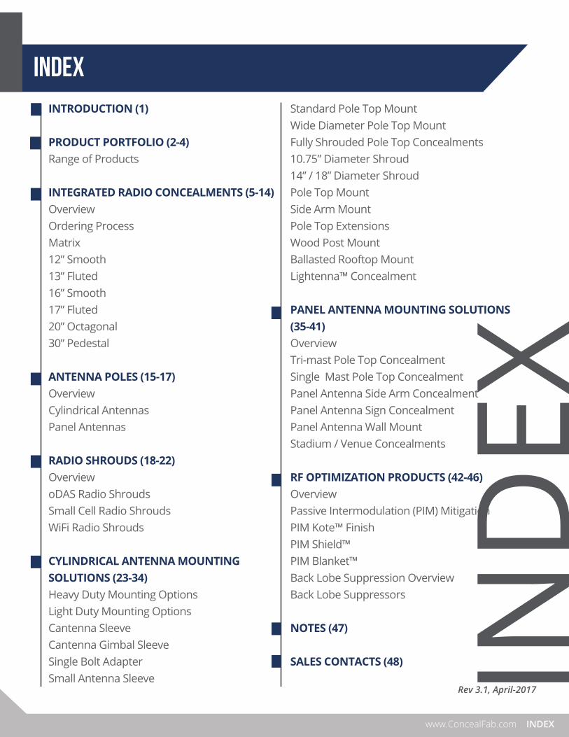
INTRODUCTION (1)
PRODUCT PORTFOLIO (2-4)Range of Products
INTEGRATED RADIO CONCEALMENTS (5-14)OverviewOrdering ProcessMatrix12” Smooth13” Fluted16” Smooth17” Fluted20” Octagonal30” Pedestal
ANTENNA POLES (15-17)OverviewCylindrical AntennasPanel Antennas
RADIO SHROUDS (18-22)OverviewoDAS Radio ShroudsSmall Cell Radio ShroudsWiFi Radio Shrouds
CYLINDRICAL ANTENNA MOUNTING SOLUTIONS (23-34)Heavy Duty Mounting OptionsLight Duty Mounting OptionsCantenna SleeveCantenna Gimbal SleeveSingle Bolt AdapterSmall Antenna Sleeve
Standard Pole Top MountWide Diameter Pole Top MountFully Shrouded Pole Top Concealments10.75” Diameter Shroud14” / 18” Diameter ShroudPole Top MountSide Arm MountPole Top ExtensionsWood Post MountBallasted Rooftop MountLightenna™ Concealment
PANEL ANTENNA MOUNTING SOLUTIONS (35-41)OverviewTri-mast Pole Top ConcealmentSingle Mast Pole Top ConcealmentPanel Antenna Side Arm Concealment Panel Antenna Sign ConcealmentPanel Antenna Wall MountStadium / Venue Concealments
RF OPTIMIZATION PRODUCTS (42-46)OverviewPassive Intermodulation (PIM) Mitigation PIM Kote™ FinishPIM Shield™PIM Blanket™Back Lobe Suppression OverviewBack Lobe Suppressors
NOTES (47)
SALES CONTACTS (48)
INDEXwww.ConcealFab.com
INDEX
INDEXwww.ConcealFab.com
Rev 3.1, April-2017

INTRODUCTION
1 ConcealFab® Corporation
ConcealFab Corporation has evolved its solution portfolio to focus on products that improve a carrier’s Signal-to-Interference-plus-Noise ratio (SINR). ConcealFab’s signal-enhancement products facilitate densification of DAS and Small Cell nodes by helping expedite zoning approvals with structurally sound, yet aesthetically pleasing product solutions. Our solution portfolio includes a full line of integrated poles, antenna poles, antenna-mounting solutions, radio cabinets / shrouds, and custom concealments (e.g., Stadium Signage and Pole-Top Shrouds). These pre-engineered infrastructure solutions are some of the most innovative and easy to deploy products available on the market today. Our noise / interference-reduction products target the mitigation of external PIM interference and antenna back lobes. External PIM is becoming an increasing problem both on rooftops and towers. ConcealFab has developed a PIM-mitigating rooftop product, for instance, which couples the latest in PIM-mitigation technology within proven rooftop products. ConcealFab’s line of back lobe suppressors assist with both sector isolation as well as PIM mitigation from discontinuities located behind antennas. Strategically, we have begun to directly partner with radio and antenna OEMs to ensure our products meet all the necessary thermal, acoustic, and RF-attenuation requirements in keeping with the OEM’s warranty conditions. Our relationships – established or emerging – are extremely important to us. We would like to thank you for choosing ConcealFab for your Small Cell or DAS projects and will do everything possible to ensure our customer’s deployments HIDE IN PLAIN SIGHT®.

HIDE IN PLAIN SIGHT®
SMALL CELL & DAS SOLUTIONS
PRODUCT PORTFOLIOOVERVIEW
• Pole top concealments• Rooftop concealments• Stadium concealments• Antenna poles• Integrated radio poles
• Radio shrouds• Back lobe suppressors• PIM mitigation
2www.ConcealFab.com

3
Attachments for Existing Poles
PRODUCT GUIDE VER. 3
PRODUCT PORTFOLIO
Pole Top - Antenna Pole Side - Antenna Pole Side - Radio Equipment
Replacement Poles
8” Smooth Antenna Pole 12” Smooth Integrated Radio 13” Fluted Integrated Radio

4www.ConcealFab.com
Custom Concealments
PRODUCT PORTFOLIO
RF Optimization Products
Stadium Concealments Sign Concealments Lightenna™
Back Lobe Suppressors PIM Blankets™ PIM Shield™

5
integrated radio concealments
OVERVIEW
ConcealFab’s line of integrated radio concealments combine all the equipment required at small cell / oDAS nodes into a single, aesthetically-pleasing design. Antennas, RF cabling, radios, power meter, power disconnect and even battery back-up can be incorporated inside a single structure providing wireless coverage and capacity with the lowest possible visual impact on the community.ConcealFab works directly with the major radio equipment OEMs to verify that appropriate air flow is provided to cool the electronics inside the pole. In addition, our solutions incorporate patented noise suppression technology to reduce fan noise for quiet operation in neighborhood environments.
Pole diameters are available ranging from 12-inch to 30-inch to accommodate a wide variety of oDAS and small cell radio configurations. ConcealFab’s steel structures are hot dip galvanized for environmental protection and painted to meet jurisdictional aesthetic requirements. For lighting applications, ConcealFab integrated radio poles can be outfitted with luminaires to closely match existing infrastructure.
Key features:
• Antenna + radio equipment housed in single structure• Eliminates need for separate radio cabinet • Small footprint on sidewalk• Lowest possible visual impact
.
PRODUCT GUIDE VER. 3

6www.ConcealFab.com
INTEGRATED RADIO CONCEALMENTS
Integrated Radio Concealments, Ordering Process
1. Define configuration: Use the matrix shown on the following pages to identify base diameters that are compatible with your radio equipment. The larger the radio, the fewer options you will have available. Then, choose the pole aesthetic (integrated pedestal, integrated base, or integrated monopole) that best suits your application.
2. Photo simulation: ConcealFab can create and provide photo simulations to realistically depict how your integrated radio concealment will look once installed. For the photo simulation to be accurate, ConcealFab needs a high-quality photograph of the proposed pole location. Think about lighting, what’s in the background, cars blocking the view of the base, etc. Frame your photograph with plenty of sky above the proposed location. If there are existing light poles / luminaires in the area that need to be replicated, please provide photos or a specification sheet. Finally, provide the antenna model, required antenna mounting height and the required luminaire mounting height. With this information, ConcealFab can provide a high quality photo simulation to help you promote the project to stakeholders.
3. Proposal: Once the stakeholders are satisfied and you are ready to proceed, ConcealFab will provide a formal proposal with an elevation drawing defining equipment locations as well as all assumptions related to proposal. The proposal will include prices for design, fabrication and delivery of the proposed solution. Lead-time will be quoted in weeks following final drawing approval.
Integrated pedestal Integrated base Integrated monopole
Antenna RAD ctr. elev.
Luminaire mounting elev.
Finish grade = 0 FT
Luminairemodel / Qty.
Radio model / Qty.
Antenna model
Combiner model / Qty.
Size / Qty. RF cables
Meter / disconnect
model
Meter elev.(if required)

7
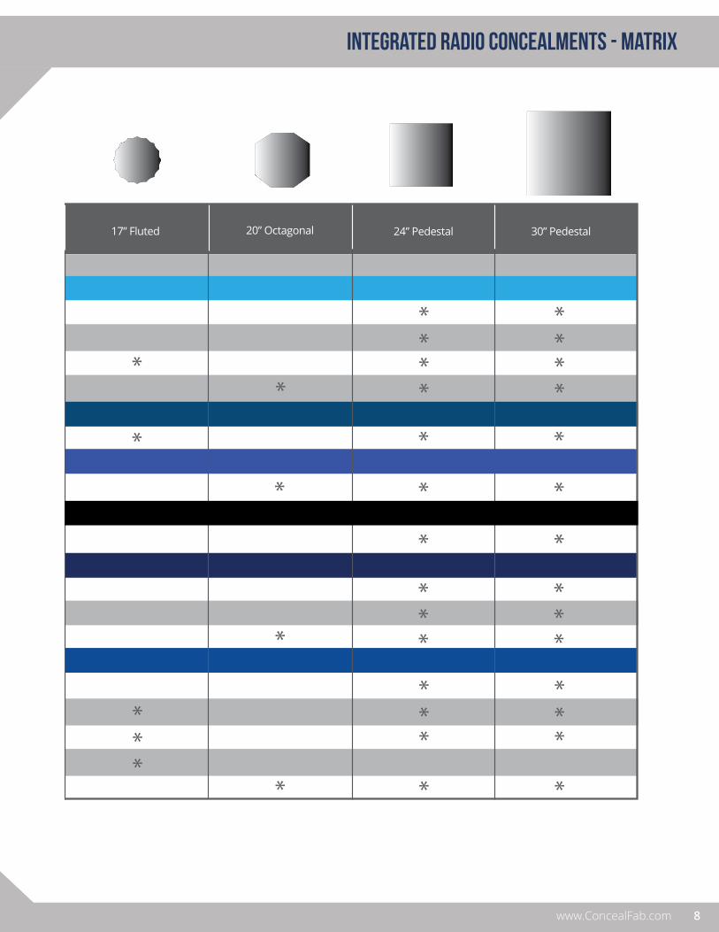
INTEGRATED RADIO CONCEALMENTS - matrix
PRODUCT GUIDE VER. 3
MANUFACTURER/ RADIO MODEL
COMMSCOPE
JMA
Medium PowerDual Band Radios
ION - M
ION - U
ION - ML
Teko
SOLiD
City DAS
PRISM
NOKIA
RRH / Corona
Flexi Zone
ERICSSON
RRUS 11 / 12
mRRU
2203
cMRO
12” Smooth
MCO, MRO
13” Fluted 20” Octagonal16” Smooth 17” Fluted 24” Pedestal 30” Pedestal
ADRF
ADX-HPR
*Optimum solution for selected radio. Radio can typically fit within any larger diameter pole.
ION-M oDAS radio installed in12” Smooth pole
8www.ConcealFab.com
INTEGRATED RADIO CONCEALMENTS - matrix
*Optimum solution for selected radio. Radio can typically fit within any larger diameter pole.
MANUFACTURER/ RADIO MODEL
COMMSCOPE
JMA
Medium PowerDual Band Radios
ION - M
ION - U
ION - ML
Teko
SOLiD
City DAS
PRISM
NOKIA
RRH / Corona
Flexi Zone
ERICSSON
RRUS 11 / 12
mRRU
2203
cMRO
12” Smooth
MCO, MRO
13” Fluted 20” Octagonal16” Smooth 17” Fluted 24” Pedestal 30” Pedestal
ADRF
ADX-HPR

12” Smooth
The most compact of ConcealFab’s line of integrated radio concealments, the 12” diameter smooth concealment is a modular, stackable design able to accommodate a variety radio configurations. The radio compartment within the pole can house Commscope ION-M oDAS radios as well as multiple Ericsson 2203 or Nokia cMRO small cell radios. Due to the small diameter, these poles are typically deployed in a monopole configuration with four radio compartments supporting multi-band / multi-operator deployments in locations that have demanding zoning requirements.
9
INTEGRATED RADIO CONCEALMENTS
PRODUCT GUIDE VER. 3
8'-0"
0" 2"
7'-9 14 "
12'-10 14 "
21'- 14 "
29'-2"
35'-0" 34'-3"
36'-5 12 "
37'-3 12 "
38'-5 12 "
GROUT (BY OTHERS)
DOUBLE ION-M SECTION
DOUBLE ION-M SECTION
INTEGRATED BASE/ POWER SECTION WITH INTERNAL SPACE TO MOUNT ELECTRICITY METER (SUBJECT TO LOCAL POWER COMPANY APPROVAL) AT 5'-3" CL (BY OTHERS), DISCONNECT (BY OTHERS) & BATTERY BACKUP EQUIPMENT (BY OTHERS)
FOUNDATION (INSTALLATION BY OTHERS)
FINISH GRADE
LUMINAIRE MOUNTING SECTION
DIPLEXER/ SPLITTER MOUNTING SECTION
CABLE CONCEALMENT SHROUD
RAD CENTER
GALTRONICS EXTENT T5622 TRI-SECTOR
ANTENNA (BY OTHERS)
CUSTOMER SPECIFIED LIGHT ARM
GE EVOLVE LED ROADWAY
LIGHTING ERS2
NOTES:POLE FINISH: GALVANIZED PER ASTM123 1.AND POWDER COATED (COLOR TBD.)
SPACER SECTION
PRELIMINARY
A
5
H
G
F
E
D
C
B
1234
H
G
F
E
D
C
B
A
4 3 2 15
Apvd:Description:Date:Rev:
A NEW RELEASE DOC03/02/15
Project:
DIMENSIONS ARE IN INCHES
Consultant:
Sheet Title:
Consultant:
003573Part Number:
CB
04/08/15
03/03/15UPDATED COBRA PER
CUST' REQ'. RECONFIG'D SPACER
ADDED DETAIL TO LUMINAIRE ARM
DOC
DOC
FRACTIONANGLEDECIMALX.XX ± 0.020
X.XXX ± 0.010 ±1° ±1/16"
DO NOTSCALE DWG
OBC 03/02/15 DOC 03/02/15
Date:Ckd By:Date:Drawn By:
© 2014 ConcealFab Corp - All Rights ReservedPERTINENT CONTRACTUAL DOCUMENTS.IN NON-DISCLOSURE AGREEMENTS ANDIS SUBJECT TO RESTRICTIONS SET FORTHUSE, REPRODUCTION, OR DISCLOSURE
PROPRIETARY INFORMATIONPH: 719-599-3400 FX: 719-599-0057COLORADO SPRINGS, CO 809073265 FILLMORE RIDGE HEIGHTS
12" ION-M MONOPOLE WITH 35' LUMINAIRE
PROPOSAL
SCALE 1:36
DR-14-0212MIAMI BEACH MONOPOLES
Commscope
Ericsson
Nokia
RADIO SECTION
RADIO SECTION

Commscope
Ericsson
Nokia
13” Fluted
0" 7 1
2 "
1'-7 12 "
20'-5"
19'-6"
24'-3"
25'-2"
28'-2"
29'- 78 "
30'-2"
31'-5 14 "
RAD CENTER
FINISH GRADE
HATCH
AIR FLOW
0" 2" (GROUT)
17'-0"
19'-4" 19'-6"
20'-5"
21'-9"
24'-1" 24'-3"
25'-2"
26'-8"
27'-9"
AA
B
B
2X BASE ACCESS HATCH 12" H X 6.75" W CLEAR OPENING. PROVISION INSIDE POLE FOR MOUNTING GROUND BAR (BY OTHERS) AND FIBER SPLICE BOX (BY OTHERS)
ALL HATCHES SECURED WITH TAMPER RESISTANT PIN-IN-TORX HARDWARE
DECORATIVE TRANSITION SHROUD
SPACE PROVIDED FOR MOUNTING 2X COMMSCOPE ION-U RADIOS (BY OTHERS)
DIPLEXER/ SPLITTER MOUNTING AREA
FOUNDATION (INSTALLATION
BY OTHERS)
FINISH GRADE
HATCH
VENT
HATCH
VENT
HATCH
COMMSCOME QUASI-OMNI ANTENNA (BY OTHERS) LUMINAIRE & ARM, STYLE &
HEIGHT AS SPECIFIED BY CUSTOMER
INSIDE12.03
OUTSIDE13.00
SECTION A-APOLE PROFILE & APPROX. POSITION OF ION-U RADIO
SCALE 1 : 4
COMMSCOPE ION-U RADIO.
(BY OTHERS)
2X SPACE FOR ROUTING COAX, FIBER, POWER ETC.
SECTION B-BSCALE 1 : 16
SCREEN MATERIAL
SPACE FOR ROUTING AND CONNECTING
COAX, POWER, FIBER ETC.
COMMSCOPE ION-U (BY OTHERS)
AIR FLOW
NOTES:APPROXIMATE POLE WEIGHT 1000 lbs EXCLUDING CUSTOMER SUPPLIED 1.EQUIPMENT (RADIOS, ANTENNA, FIBER SPLICE BOX & ANCILLIARY EQUIPMENT).AVAILABLE IN A VARIETY OF COLORS & WITH OPTIONAL ANTI-GRAFFITI 2.COATING.OPTIONAL DECORATIVE BASE COVER CAN BE SUPPLIED AS REQUIRED.3.
A
5
H
G
F
E
D
C
B
1234
H
G
F
E
D
C
B
A
4 3 2 15
Apvd:Description:Date:Rev:
A NEW RELEASE DOC06/12/15
Project:
DIMENSIONS ARE IN INCHES
Consultant:
Sheet Title:
Consultant:
004473Part Number:
FRACTIONANGLEDECIMAL X.XX ± 0.020X.XXX ± 0.010
X ±1° X.X ± 0.5° ±1/16"
DO NOTSCALE DWG
OBC 06/12/15 DOC 06/12/15
Date:Ckd By:Date:Drawn By:
© 2014 ConcealFab Corp - All Rights ReservedPERTINENT CONTRACTUAL DOCUMENTS.IN NON-DISCLOSURE AGREEMENTS ANDIS SUBJECT TO RESTRICTIONS SET FORTHUSE, REPRODUCTION, OR DISCLOSURE
PROPRIETARY INFORMATIONPH: 719-599-3400 FX: 719-599-0057COLORADO SPRINGS, CO 809073265 FILLMORE RIDGE HEIGHTS
13" FLUTED ION-U MONOPOLE W/
LUMINAIRE
SCALE 1:32
DR-15-0219SAVANNAH, GA
2X ION-U MONOPOLE
Commscope
Ericsson
Nokia
ConcealFab’s 13” integrated radio concealment includes a fluted profile to better match the more decorative and ornate light poles often found in city environments. The radio compartments within the pole can house Commscope ION-M or ION-U oDAS radios as well as a variety of low power small cell radios from Ericsson and Nokia. These poles are typically supplied as a single-piece monopole with multiple radio compartments per pole. Decorative clamshell bases are available to conceal the anchor bolts and match existing poles in the area.
10www.ConcealFab.com
INTEGRATED RADIO CONCEALMENTS

11
INTEGRATED RADIO CONCEALMENTS
PRODUCT GUIDE VER. 3
16” Smooth
AA
CABLE CONCEALMENT SKIRT / DIPLEXER AREA
CSS CYL-X7CAP-2CANTENNA (BY OTHERS)
EXTENSION SECTION
LIGHTARM WITHCOBRAHEAD LUMINAIRE
TRANSITION SHROUD
RADIO SECTION(CAPABLE OF HOLDING UP TO TWO (2) TEKO REMOTE UNITS)
PEDESTAL SECTION
15'-0"
3'-0"
6.63
16.00
0
2'-0"
11'-0" 11'-10"
25'-9"
29'-5"
24'-11"
8'-0"
28'-5" RAD CENTER
FOUN
DA
TION
(BY
OTH
ERS)
FOUN
DA
TION
(BY
OTH
ERS)
1.375
16.13
0
2.0
0
18.
00
20.
00
2.5
0
17.
50
0 2.00 2.50
17.50 18.00 20.00
SECTION A-ASCALE 1 : 10
1.50" THK.A36 STEEL
PRELIMINARY
NOTES:LIGHTARM MODEL, LIGHTARM HEIGHT & LIGHTARM LENGTH CAN BE VARIED.1.FOUNDATION DEPTH AND DIAMETER CAN BE ADJUSTED DEPENDING ON POLE HEIGHT & SOIL COMPOSITION.2.POLE MOUNTED BANNERS ARE OPTIONAL.3.
SIDE ELEVATION VIEW FRONT ELEVATION VIEW BASE PLATE W/ ANCHOR BOLT LOCATIONS(ANCHOR BOLTS ARE 1.25")
16" O.D. SMOOTH INTEGRATED POLE
SAMPLE ELEVATION DRAWING
TIL-15-071516" O.D. SMOOTH INTEGRATED POLE 004753
A
B
C
D
234
4 3 2 1
1
Drawn By: Date: Ckd By: Date:
10/06/15DOC10/06/15MDH DOC10/06/15A NEW RELEASE
Apd:Description:Date:Rev: Sheet Title:
±1/16"X ±1° X.X ± 0.5°
X.X ± 0.050 X.XX ± 0.020X.XXX ± 0.010
DECIMAL ANGLE FRACTION
DIMENSIONS ARE IN INCHES
DO NOTSCALE DWG
E
F
G
H
A
B
C
D
E
F
G
H
PH: 719-599-3400 FX: 719-599-0057COLORADO SPRINGS, CO 80907
3525 NORTH CASCADE AVENUE
© 2015 ConcealFab Corp - All Rights ReservedPERTINENT CONTRACTUAL DOCUMENTS.IN NON-DISCLOSURE AGREEMENTS ANDIS SUBJECT TO RESTRICTIONS SET FORTHUSE, REPRODUCTION, OR DISCLOSUREPROPRIETARY INFORMATION
Drawing / Part Number:
Project:
Consultant:
Sheet:Sheet Scale:
1:50 1 OF 1 ARev:
ConcealFab’s 16” integrated radio concealment provides a smooth profile system able to accommodate larger oDAS radios such asJMA / Teko and Commscope ION-ML. This system can be deployed as a continuous diameter monopole but is more frequently deployed as an integrated base with smaller diameter extension pole. Additional radio compartments are typically incorporated to support MIMO operation in multiple frequency bands.
Commscope
JMA

12www.ConcealFab.com
INTEGRATED RADIO CONCEALMENTS
17” Fluted
AA
CABLE CONCEALMENT SKIRT / DIPLEXER AREA
CSS CYL-X7CAP-2CANTENNA (BY OTHERS)
EXTENSION SECTION
DECORATIVE LIGHTARMWITH LUMINAIRES
TRANSITION SHROUD
RADIO SECTION(CAPABLE OF HOLDING UP TO TWO (2) TEKO REMOTE UNITS)
PEDESTAL SECTION(DECORATIVE SHROUD OUTLINED)
15'-0"
3'-0"
6.63
17.00
2.00 0
2'-0"
11'-0" 11'-10"
22'-6"
26'-2"
16'-0"
25'-2" RAD CENTER
FOUN
DA
TION
(BY
OTH
ERS)
FOUN
DA
TION
(BY
OTH
ERS)
FINISH GRADE
1.375
16.13
0
0 2.00
18.00 20.00
2.50
17.50
2.5
0 2
.00
17.
50
18.
00
20.
00
SECTION A-ASCALE 1 : 10
1.50" THK.A36 STEEL
PRELIMINARY
NOTES:LIGHTARM MODEL, LIGHTARM HEIGHT & LIGHTARM LENGTH CAN BE VARIED.1.FOUNDATION DEPTH AND DIAMETER CAN BE ADJUSTED DEPENDING ON POLE HEIGHT & SOIL COMPOSITION.2.POLE MOUNTED BANNERS ARE OPTIONAL.3.
SIDE ELEVATION VIEW FRONT ELEVATION VIEW BASE PLATE W/ ANCHOR BOLT LOCATIONS(ANCHOR BOLTS ARE 1.25")
17" O.D. FLUTED INTEGRATED POLE
SAMPLE ELEVATION DRAWING
TIL-15-071517" O.D. FLUTED
INTEGRATED POLE 004754
A
B
C
D
234
4 3 2 1
1
Drawn By: Date: Ckd By: Date:
10/06/15DOC10/06/15MDH DOC10/06/15A NEW RELEASE
Apd:Description:Date:Rev: Sheet Title:
±1/16"X ±1° X.X ± 0.5°
X.X ± 0.050 X.XX ± 0.020X.XXX ± 0.010
DECIMAL ANGLE FRACTION
DIMENSIONS ARE IN INCHES
DO NOTSCALE DWG
E
F
G
H
A
B
C
D
E
F
G
H
PH: 719-599-3400 FX: 719-599-0057COLORADO SPRINGS, CO 80907
3525 NORTH CASCADE AVENUE
© 2015 ConcealFab Corp - All Rights ReservedPERTINENT CONTRACTUAL DOCUMENTS.IN NON-DISCLOSURE AGREEMENTS ANDIS SUBJECT TO RESTRICTIONS SET FORTHUSE, REPRODUCTION, OR DISCLOSUREPROPRIETARY INFORMATION
Drawing / Part Number:
Project:
Consultant:
Sheet:Sheet Scale:
1:50 1 OF 1 ARev:
ConcealFab’s 17” integrated radio concealment provides a fluted profile able to accommodate larger oDAS radios such as JMA / Teko and Commscope ION-ML. A fluted profile is often required to more closely match the more decorative and ornate light poles often found in city environments. This system can be deployed as a continuous diameter monopole but is more frequently deployed as an integrated base with smaller diameter extension pole. Decorative clamshell bases are available to conceal the anchor bolts and match existing poles in the area.
CommScope
JMA
Commscope
JMA
13
INTEGRATED RADIO CONCEALMENTS
PRODUCT GUIDE VER. 3
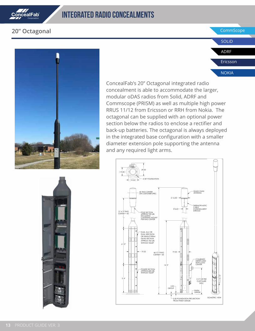
20” Octagonal
ConcealFab’s 20” Octagonal integrated radio concealment is able to accommodate the larger, modular oDAS radios from Solid, ADRF and Commscope (PRISM) as well as multiple high power RRUS 11/12 from Ericsson or RRH from Nokia. The octagonal can be supplied with an optional power section below the radios to enclose a rectifier and back-up batteries. The octagonal is always deployed in the integrated base configuration with a smaller diameter extension pole supporting the antenna and any required light arms.
5'-4"
6'-10"
31'-6" IF RADCENTER = 45'
19.50
45' RAD CENTEROR CUSTOMER SPEC
DUAL ALU ORDUAL ERICSSONOR SINGLE PRISMQUAD SECTIONAPPROX 700 LBSWITHOUT EQUIP
POWER SECTIONAPPROX 600 LBSWITHOUT EQUIP
POLE SECTIONAPPROX 750 LBSINCLUDING CANTENNA MOUNTPER RAD CENTER
ISOMETRIC VIEW
19.50
19.50 29.00
30" FOUNDATION
46'-0" IF RADCENTER = 45'
2.00 FOUNDATION PROJECTIONFROM FINISH GRADE
2.00GROUT
6.63
19.50
16.00
14'-0"
5'-0" OR PERCUSTOMER
SPEC
FINISH GRADE
COMBINED METER MAIN WITH LOAD CENTER
THERMOPLASTIC CABLE CONCEALMENT SHROUD
QUASI-OMNIANTENNA
A
B
C
D
234
4 3 2 1
1
Drawn By: Date: Ckd By: Date:
10/19/15OBC10/19/15SDR DOC10/22/15A NEW RELEASE
Apd:Description:Date:Rev:
OCTAGONAL INTEGRATED POLE,
PRODUCT DRAWING
Sheet Title:
±1/16"X ±1° X.X ± 0.5°
X.X ± 0.050 X.XX ± 0.020X.XXX ± 0.010
DECIMAL ANGLE FRACTION
DIMENSIONS ARE IN INCHES
DO NOTSCALE DWG
E
F
G
H
A
B
C
D
E
F
G
H
PH: 719-599-3400 FX: 719-599-0057COLORADO SPRINGS, CO 80907
3525 NORTH CASCADE AVENUE
© 2015 ConcealFab Corp - All Rights ReservedPERTINENT CONTRACTUAL DOCUMENTS.IN NON-DISCLOSURE AGREEMENTS ANDIS SUBJECT TO RESTRICTIONS SET FORTHUSE, REPRODUCTION, OR DISCLOSUREPROPRIETARY INFORMATION
005104Drawing / Part Number:
OCTAGONAL INTEGRATED POLE
Project:
DR-15-0724
Consultant:
Sheet:Sheet Scale:
1:24 1 OF 1 ARev:
CommScope
Ericsson
NOKIA
SOLiD
ADRF

14www.ConcealFab.com
INTEGRATED RADIO CONCEALMENTS
CommScope
Ericsson
NOKIA
SOLiD
ADRF
24” and 30” Pedestal
ConcealFab’s pedestal integrated radio concealments are a highly flexible alternative for deploying a variety of oDAS and small cell radios in urban environments. The vented square base can accommodate multiple small cell and oDAS radios with only minor changes to mounting hardware. As radio requirements change, this system can be easily modified to accommodate new deployment needs. Large doors and removable side access panels provide maximum access to internal equipment during initial installation and service.
CommScope
Ericsson
NOKIA
SOLiD
ADRF
10.75
2.00 GROUT
0 FINISH GRADE
24'-4 12 "
28'- 12 "
27'- 12 " RAD CENTER
2" FOUNDATION (BY OTHERS)
4'-10"
EXTENSION SECTION
TRANSITION SHROUD
PEDESTAL SECTION WITH 3 ACCESSIBLE SIDESHOUSES RADIOS AND ANCILLARY EQUIPMENT
CABLE CONCEALMENT
SHROUD
QUASI-OMNI ANTENNA
(BY OTHERS)
ISOMETRIC VIEWSCALE 1 : 42
30.00
30.00
PART NUMBER DESCRIPTION
000000
A
B
C
D
234
4 3 2 1
1
Drawn By: Date: Ckd By: Date:
A NEW RELEASE
Apd:Description:Date:Rev: Sheet Title:
±1/16"X ±1° X.X ± 0.5°
X.X ± 0.050 X.XX ± 0.020X.XXX ± 0.010
DECIMAL ANGLE FRACTION
DIMENSIONS ARE IN INCHES
DO NOTSCALE DWG
E
F
G
H
A
B
C
D
E
F
G
H
PH: 719-599-3400 FX: 719-599-0057COLORADO SPRINGS, CO 809073525 NORTH CASCADE AVENUE
© 2016 ConcealFab Corp - All Rights ReservedPERTINENT CONTRACTUAL DOCUMENTS.IN NON-DISCLOSURE AGREEMENTS ANDIS SUBJECT TO RESTRICTIONS SET FORTHUSE, REPRODUCTION, OR DISCLOSUREPROPRIETARY INFORMATION
00000000Drawing Number:
Project:
Consultant:
Sheet:Sheet Scale:
1:36 1 OF 1

15
antenna poles
PRODUCT GUIDE VER. 3
OVERVIEW
When an existing pole is unable to support the added load of wireless equipment, ConcealFab’s antenna pole concealments are a perfect solution. These aesthetically pleasing designs incorporate convenient mounting for small cell / oDAS antennas with the structural integrity needed to support external radio and power line equipment. Structural accommodations can also be made for road signs, pedestrian cross-walks and banners.
ConcealFab’s antenna poles can be designed to accommodate quasi-omni antennas as well as larger panel antenna concealments. The poles can be produced in a variety of shapes and sizes and outfitted with luminaires as required to match existing infrastructure. ConcealFab’s antenna poles are hot dip galvanized for environmental protection and can be painted to meet jurisdictional aesthetic requirements.
Key features:
• Designed to support mechanical load of wireless equipment
• Integrated antenna mounting / concealment
• Blends with existing infrastructure

16www.ConcealFab.com
antenna poles
Cylindrical Antennas
Antenna poles for cylindrical antennas are aesthetically pleasing replacement poles with convenient mounting provisions for a wide variety of small cell antennas. Featuring ConcealFab’s universal cantenna sleeve and cable concealment shroud, these poles easily accommodate small cell antennas from manufacturers such as Amphenol, Commscope, Galtronics, JMA and Kathrein. If antenna requirements change in the future, only minor hardware changes are required to accommodate a different antenna model. Poles are available with optional radio concealment shrouds to protect radio equipment and can be outfitted with decorative luminaires to match existing infrastructure in city environments.
21 18 "
8" NOM SCH 40
0
6'-8 1116 " (3"X5" HANDHOLE)
7'- 18 "
9'- 1116 "
12'-0"
17'-10 716 " (3"X5" HANDHOLE)
22'-1 316 "
26'-3 34 "
18'-2 316 "
RAD CENTER 25'-1 78 "
8 716 " (3" X 5" HANDHOLE)
7'-7 78 "
11'-7 116 " (3" X 5" HANDHOLE)
8'-8 516 " (3"X5" HANDHOLE)
FOUNDATION(BY OTHERS)
14-1/2" SMALL CELL AMPHENOL CANTENNA
CUT070X06FXYZ0(BY OTHERS)
CONCEALFAB UNIVERSAL CANTENNA MOUNT
FINISHGRADE
CONCEALFAB RADIO SHROUD FOR 2X COMMSCOPE ION-M RADIOS20" W X 45" H X 14" D
MILBANK U7588-XLMETER BOX(BY OTHERS)
SQUARE D QO1DM10030TRBRDISCONNECT BOX / MANUAL TRANSFER SWITCH(BY OTHERS)
HOLOPHANE PTUELUMINAIRE
CONCEALFAB MOUNTING SLEEVE & BRACKETS FOR
4X CLEARCOMM CCHC-102-XD COMBINERS
CONCEALFABLUMINAIRE ARM
GROUT (2.00")
GROUND BARUGBKIT-0210-T
(BY OTHERS)
GROUND BARUGBKIT-0210-T(BY OTHERS)
CONCEALFAB CABLE CONCEALMENT SHROUD
CLMTR
NOTES:APPROX. WEIGHT: 1498.19 LBS.1.MATERIAL: 2.BREAK ALL SHARP CORNERS AND EDGES. 3.
4.5.6.
TOP OF ANTENNA
TOP OF POLE
A
B
C
D
234
4 3 2 1
1
Drawn By: Date: Ckd By: Date:
07/13/16MEA06/16/16BHB DOC07/13/16A NEW RELEASE
Apd:Description:Date:Rev:
POLE, ENGINEERED, SMOOTH, 8" NOM X 25' RAD, 2X ION-M, PTUE,
TOP ASSEMBLY
Sheet Title:
±1/16"X ±1° X.X ± 0.5°
X.X ± 0.050 X.XX ± 0.020X.XXX ± 0.010
DECIMAL ANGLE FRACTION
DIMENSIONS ARE IN INCHES
DO NOTSCALE DWG
E
F
G
H
A
B
C
D
E
F
G
H
PH: 719-599-3400 FX: 719-599-0057COLORADO SPRINGS, CO 809073525 NORTH CASCADE AVENUE
© 2016 ConcealFab Corp - All Rights ReservedPERTINENT CONTRACTUAL DOCUMENTS.IN NON-DISCLOSURE AGREEMENTS ANDIS SUBJECT TO RESTRICTIONS SET FORTHUSE, REPRODUCTION, OR DISCLOSUREPROPRIETARY INFORMATION
007254Drawing / Part Number:
ROCHESTER, NY, 2X ION-M, 8.625" O.D. SMOOTH
ENGINEERED POLE
Project:
DR-16-0211
Consultant:
Sheet:Sheet Scale:
1:27 1 OF 1 ARev:

17
antenna poles
PRODUCT GUIDE VER. 3
Panel Antennas
Heavy duty replacement poles are also available to support panel antenna concealments. Paired with one of ConcealFab’s single mast or tri-mast antenna concealments, this system gives RF engineers maximum flexibility to optimize RF performance. With RF feed-line cables and antennas hidden from public view these systems often gain quick approval in urban / suburban environments. Poles are available with optional radio concealment shrouds to protect radio equipment and can be outfitted with luminaires to match existing lighting.
1
A
C
1
1
A
±1/16"
FRACTION
F
A
C
F
©
PROPRIETARY INFORMATION
POLE TOP CONCEALMENT
ARRANGEMENT

2www.ConcealFab.com
radio shrouds
18www.ConcealFab.com
OVERVIEW
Radio concealment shrouds provide a convenient and functional method for mounting the radio equipment and supporting components at cell sites. These shrouds not only improve the appearance of the site but also protect the equipment and sensitive connections from vandalism.
In addition to the radio, concealment shrouds can be configured to house the power meter, disconnect, load center, diplexers, fiber management boxes, grounding bars, etc. Radio shrouds are designed to allow heat generated within the enclosure to be removed by natural convection or with the assistance of fans incorporated into the enclosure. Radio shrouds are available in both pole mount and ground mount configurations to suit individual site requirements.
ConcealFab’s radio equipment shrouds are manufactured using stamped aluminum or steel, depending on the application, and powder coated for long term environmental protection. ConcealFab’s shrouds are designed to be compliant with UL and GR487 requirements and can be outfitted with ConcealFab’s patented sound suppression technology to reduce fan noise in neighborhood environments.
PROTECTED UNPROTECTED

19
radio shrouds
PRODUCT GUIDE VER. 3
oDAS Radio Shrouds
ConcealFab’s oDAS radio concealment shrouds are designed to accommodate a wide variety oDAS radios. These cabinets are designed using the same philosophy as our line of integrated radio pole concealments, targeting the most compact design possible and leveraging our patented and proprietary techniques for sound suppression, cable management and thermal dissipation. Our radio shrouds are typically designed to accommodate two oDAS radios with appropriate room to route RF cables and make all required electrical and optical connections. Pole mount as well as ground mount shrouds are available to meet deployment requirements.
Shroud with door open
Door closed, measuring fan noise

20www.ConcealFab.com
Radio shrouds
Small Cell Radio Shrouds
ConcealFab’s small cell radio shroud is designed to efficiently package a host of telecom equipment in the smallest envelope possible. Space is available for two high power radios or a larger number of low power small cell radios mounted to opposite sides of a central septum. Room is provided for multiple RF combiners as well as a fiber optic drop / add module for WDM applications. Clam-shell style doors open wide to each side providing maximum access for installation and maintenance. Due to the large number of vents on the sides and top of the enclosure, sufficient air flow is achieved to passively cool the enclosed radio equipment. The small cell radio shroud has provision to be either pole mounted or ground mounted.
An optional power cabinet attaches to the bottom of the shroud supporting 3RU of 19” rack space and sufficient battery capacity to provide 2 hours back-up power for typical radio configurations. The initial configuration was designed for a 1 RU, 19” rack-mounted rectifier and a 1 RU DC distribution shelf. An additional 1RU shelf is available for an AC distribution unit with surge suppression if desired.
RadioCompartment A
Optical Fiber Management
Batteries
RadioCompartment B
Combiners
Rectifier / DC Distribution

21
radio shrouds
PRODUCT GUIDE VER. 3
WiFi Radio Shrouds
In addition to concealments for small cell and oDAS radios, ConcealFab has experience designing and deploying solutions for WiFi applications. Since WiFi access points typically have antennas integrated with the radio, enclosures must be manufactured using materials with low RF loss in the 2.5 GHz and 5.8 GHz frequency bands. ConcealFab’s concealment materials have been tested up to 100 GHz and exhibit exceptional performance well into the mmW frequency bands.
A particularly challenging deployment entailed concealing two Ruckus WiFi access points on street lights on Boston’s historic Newbury Street. Given the high-profile nature of this deployment, multiple city agencies had to sign off on the aesthetics to sanction the deployment. The existing infrastructure consisted of hexagonal concrete light poles. ConcealFab replaced these poles with hexagonal steel poles coated to mimic concrete. ConcealFab also applied concrete texture to the hexagonal radio concealment shrouds. This design not only met the aesthetic requirements of the stakeholders but also met the requirements for RF transparency, structural integrity, lighting and thermal compliance.

22www.ConcealFab.com
Radio shrouds

23
cylindrical antenna mounting solutions
PRODUCT GUIDE VER. 3
HEAVY DUTYHeavy Duty Mounting Options
Standard MountRefer to Page 27
for Details
Optional CableConcealment Shroud
ConcealFab manufactures a wide variety of mounting solutions for the quasi-omni “cantennas” commonly deployed at multi-band small cell and oDAS sites. Mounting kits with optional cable concealment shrouds are available to securely attach these larger wind load antennas to existing wood, metal or concrete poles as well as to other structures. ConcealFab’s “cantenna sleeve” design enables each mount to support a variety of antenna models, eliminating the need for a different mounting kit for each brand of antenna.
Specifying a complete mounting solution requires multiple part numbers:
1 – Cantenna sleeve
2 – Mount
3 – Shroud (optional)
ConcealFab’s mounting solutions includeour proprietary PIM Kote™ finish tominimize passive intermodulation (PIM.)
Wide DiameterMount
Refer to Page 28for Details
Ballasted Rooftop MountRefer to Page 33
for Details
Side Arm MountRefer to Page 31
for Details
Wood Post Mount
Refer to Page 32for Details
Pole Top Extension
Refer to Page 32for Details
Cantenna Gimbal SleeveRefer to Page 25 for Details
Standard Cantenna SleeveRefer to Page 25 for Details

24www.ConcealFab.com
cylindrical antenna mounting solutions
Optional Cable Concealment Shroud
Light Duty Pole Top MountRefer to Page 30
for Details
Light Duty Side Arm Mount
Refer to Page 30for Details
Light Duty Pole Top Extension
Refer to Page 32for Details
Lighter duty mounting solutions are available for lower wind load quasi-omni antennas used in higher frequency applications. These mounts include an adapter to convert the antenna manufacturer’s bolt pattern to a single mounting bolt which attaches directly to the light duty pole top mount or the light duty side arm mount. An optional cable concealment shroud is available to hide RF feed-line cables from public view.
Lower wind load antennas can be attached to any of ConcealFab’s heavy duty mounts using a single bolt adapter and small antenna sleeve. Specifying a complete mounting system requires up to four part numbers, depending on the desired mount:
1 – Single bolt adapter
2 – Small antenna sleeve (optional)
3 – Mount
4 – Shroud (optional)
LIGHT DUTYLight Duty Mounting Options
Single Bolt AdapterRefer to Page 26
for Details
Small Antenna SleeveRefer to Page 26
for Details
AnyHeavy Duty
MountRefer to Page 23
for Details

25
cylindrical antenna mounting solutions
PRODUCT GUIDE VER. 3
Cantenna Sleeve
PN - PPPPPP-S-F
HEAVY DUTY
2” Nom
S = Size of nom pipe stub
BlackBrownGraySilver
F = Finish Code
1
1234
AmphenolKathreinJMA GaltronicsCommScope
PPPPPP = Base Part #
007941007942
007943
Cantenna Gimbal Sleeve
PN - PPPPPP-S-F
2” Nom
S = Size of nom pipe stub
1
AmphenolKathreinJMA GaltronicsCommScope
PPPPPP = Base Part #
007966007967
007968
007942
007943
Antenna interface hardware to be the same as shown in Universal Cantenna Sleeve section
HEAVY DUTY
Cantenna sleeves are used to create a standard interface between an antenna manufacturer’s bolt pattern and a ConcealFab mounting kit. Cantenna sleeves are designed to mount to the 2 inch nominal (2.375 inch OD) pipe stub on ConcealFab mounting kits, enabling 360 degree azimuth adjustment.
007941
The gimbal sleeve can be used with any ConcealFab heavy duty mount to correct for up to 15 degrees error in pitch / roll of the installed mount. This adjustment is often required on direct-bury wooden poles that are leaning in one direction. The gimbal sleeve is taller than a standard sleeve and is not compatible with most cable concealment shrouds
F = Finish Code
02
None (Stainless Steel)Brown
26www.ConcealFab.com
cylindrical antenna mounting solutions
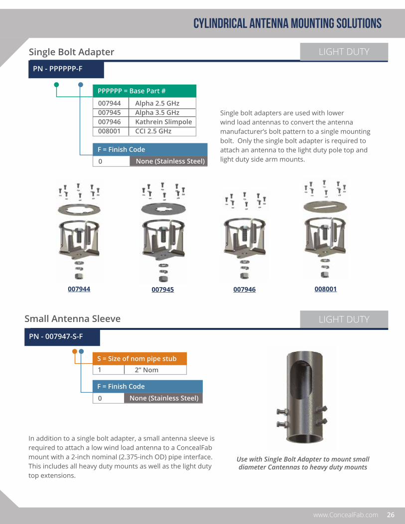
LIGHT DUTY
PN - PPPPPP-F
Alpha 2.5 GHzAlpha 3.5 GHzKathrein SlimpoleCCI 2.5 GHz
PPPPPP = Base Part #
007944007945007946008001
LIGHT DUTY
PN - 007947-S-F
2” Nom
S = Size of nom pipe stub
1
Small Antenna Sleeve
Single Bolt Adapter
007944 007946
Use with Single Bolt Adapter to mount small diameter Cantennas to heavy duty mounts
Single bolt adapters are used with lower wind load antennas to convert the antenna manufacturer’s bolt pattern to a single mounting bolt. Only the single bolt adapter is required to attach an antenna to the light duty pole top and light duty side arm mounts. None (Stainless Steel)
F = Finish Code
0
In addition to a single bolt adapter, a small antenna sleeve is required to attach a low wind load antenna to a ConcealFab mount with a 2-inch nominal (2.375-inch OD) pipe interface. This includes all heavy duty mounts as well as the light duty top extensions.
None (Stainless Steel)
F = Finish Code
0
007945 008001

27
cylindrical antenna mounting solutions
PRODUCT GUIDE VER. 3
Standard Pole Top Mount
PN - 007948-F (Bracket)
ConcealFab’s standard pole top mount is designed to attach an antenna to the top of an existing wood, concrete or steel pole ranging from 5.0 to 8.37 inch outside diameter. These mounts are engineered to support the sail area of typical 2-FT tall, multi-band small cell / oDAS antennas in extreme exposure zones. An optional cable concealment shroud is available to hide the RF feed-line connections and mounting brackets from public view. Order sleeve separately.
BlackBrownGraySilver
F = Finish Code
1234
PN - PPPPPP-F (Shroud)
BlackBrownGraySilver
F = Finish Code
1234
AmphenolKathreinJMA GaltronicsCommScope
PPPPPP = Base Part #
007949
007950
HEAVY DUTY
007949
007950

28www.ConcealFab.com
cylindrical antenna mounting solutions
Wide Diameter Pole Top Mount
ConcealFab’s wide diameter pole top mount is designed to attach an antenna to the top of an existing wood, concrete or steel pole ranging from 5.25 to 14.12 inch outside diameter. These mounts are engineered to support the sail area of typical 2-FT tall, multi-band small cell / oDAS antennas in extreme exposure zones. An optional cable concealment shroud is available to hide the RF feed-line connections and mounting brackets from public view. Order sleeve separately.
BlackBrownGraySilver
F = Finish Code
1234
BlackBrownGraySilver
F = Finish Code
1234
AmphenolKathreinJMA GaltronicsCommScope
PPPPPP = Base Part #
007952
007953
PN - 007951-F (Bracket) PN - PPPPPP-F (Shroud)
HEAVY DUTY
007952
007953

29
cylindrical antenna mounting solutions
PRODUCT GUIDE VER. 3
Fully Shrouded Pole Top Concealments
10.75” Diameter Shroud
The 10.75 inch diameter pole top shroud is designed to enclose a cylindrical antenna at the top of an existing 3.25 to 6.63 inch outside diameter pole. The shroud consists of a field removable top section to hide the serving antenna and a two-piececlam-shell lower section to hide the RF feed-lines and mounting brackets to provide a smooth transition to the pole outside diameter.
14” / 18” Diameter Shroud
The 14.0-inch and 18.0-inch diameter pole top shrouds are designed to enclose a cylindrical antenna as well as the small cell radio equipment at the top of a new or existing pole. Both products include a welded stainless steel internal structure with off-set mounting pipe to provide maximum volume for mounting radio equipment below the serving antenna. The units can be band clamped to existing poles ranging from 4.0 to 15.25 inch outside diameter or bolted directly to the top of new poles. Transition shrouds are available to hide the RF feed-lines and mounting brackets and provide an aesthetically pleasing transition to the pole outside diameter.
ConcealFab offers an assortment of mounting solutions that fully enclose the small cell radio equipment at the top of new or existing street lights or utility poles. The enclosures are manufactured from low RF loss ABS plastic and factory painted to achieve UV stability. Custom paint colors are available upon request. Perforated vents can be included to allow airflow for cooling of the enclosed electronics. For ordering information, please contact ConcealFab customer service.

30www.ConcealFab.com
cylindrical antenna mounting solutions
Pole Top Mount LIGHT DUTY
Side Arm Mount
PN - 007958-F (Bracket)
BlackBrownGraySilver
F = Finish Code
1234
ConcealFab’s light duty side arm mount is designed to attach a low wind load cylindrical antenna to the side of an existing pole or structure. RF cables can be concealed inside the arm, exiting either into the pole or to the outside surface of the pole. An optional cable concealment shroud is available to hide the RF feed-line connections from public view. Order single bolt adapter separately.
PN - 007959-F (Bracket) PN - 007954-F (Shroud)
BlackBrownGraySilver
F = Finish Code
1234
BlackBrownGraySilver
F = Finish Code
1234
ConcealFab’s light duty pole top mount is designed to attach a low wind load cylindrical antenna to the top of an existing wood, concrete or steel pole ranging from 3.25 to 6.63 inch outside diameter. An optional cable concealment shroud is available to hide the RF feed-line connections from public view. Order single bolt adapter separately. The light duty cable
concealment shroud is designed to work with both the light duty pole top and light duty side arm mounts.
31
cylindrical antenna mounting solutions
PRODUCT GUIDE VER. 3
Side Arm Mount
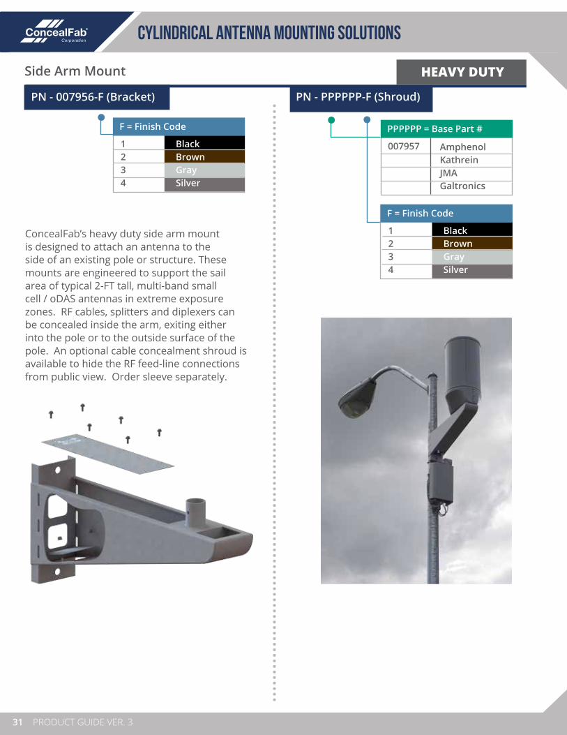
PN - 007956-F (Bracket)
BlackBrownGraySilver
F = Finish Code
1234
ConcealFab’s heavy duty side arm mount is designed to attach an antenna to the side of an existing pole or structure. These mounts are engineered to support the sail area of typical 2-FT tall, multi-band small cell / oDAS antennas in extreme exposure zones. RF cables, splitters and diplexers can be concealed inside the arm, exiting either into the pole or to the outside surface of the pole. An optional cable concealment shroud is available to hide the RF feed-line connections from public view. Order sleeve separately.
HEAVY DUTY
PN - PPPPPP-F (Shroud)
AmphenolKathreinJMA Galtronics
PPPPPP = Base Part #
007957
BlackBrownGraySilver
F = Finish Code
1234

32www.ConcealFab.com
cylindrical antenna mounting solutions
Pole Top Extensions
PN - 007960-H-F
3’4’5’
H = Mast Height
123
BlackBrownGraySilver
F = Finish Code
1234
Wood Post Mount
PN - 007961-H-F
HEAVY DUTY
HEAVY DUTY
Brown
F = Finish Code
1
ConcealFab offers a variety of pole top extensions to increase the antenna RAD center above the top of an existing pole. Pole top extensions may be required for safety reasons at power line sites or to improve coverage / reduce PIM when luminaires are positioned close to the top of an existing pole. Order sleeve separately.
LIGHT DUTY
3’4’5’
H = Mast Height
123
BlackBrownGraySilver
F = Finish Code
1234
PN - 007962-H-F
• 5.25 to 14.12 inch outside pole diameter.• For typical 2-FT tall, multi-band antennas in
extreme exposure zones.
• 3.25 to 6.63 inch outside pole diameter.• For smaller sail area antennas
ConcealFab’s wood post mount provides a convenient way to attach a small cell antenna to an existing wooden structure. The mount is bolted to an existing 4-inch nominal (3.5-inch actual) wooden member and is available with a variety of mast lengths to place the antenna RAD center at the required elevation. Order sleeve separately.
1’2’3’
H = Mast Height
123

33
cylindrical antenna mounting solutions
PRODUCT GUIDE VER. 3
Ballasted Rooftop Mount
PN - 007963-H-M-F (Mount)
4.6 FT – Optimized for 6 FT vent6.6 FT – Optimized for 8 FT vent10 FT – Field trim to desired height
H = Mast Height
123
PN-PPPPPP-H-F (Vent Concealment)
HEAVY DUTY
ConcealFab’s ballasted rooftop mount allows small cell antennas to be discreetly deployed on existing rooftops without penetrating the roof membrane. Up to three optional radio mounting masts can attach to each mount. An adjustable version for sloped rooftops is available. Please contact ConcealFab customer service for additional information. Order sleeve and vent concealment separately.
An optional RF-transparent vent concealment is available to hide the antenna and RF feed-line cables from public view. This concealment is secured to the 2-inch nominal (2.375-inch OD) mounting mast, allowing it to be deployed on any vertical pipe of sufficient length. The optimized mast pipe lengths referenced in the Ballasted Rooftop Mount section place the bottom of the concealment 2 FT above the rooftop.
None1 Radio Mast2 Radio Masts3 Radio Masts
M = # of Radio Masts
0123
6’8’
H = Height of Concealment
12
BrownSilver
F = Finish Code
24
F = Finish Code
24
BrownSilver
16 inch diameter, segmented profile16 inch diameter, smooth profile18 inch diameter, segmented profile18 inch diameter, smooth profile
PPPPPP = Base Part #
007964008195008002008196
34www.ConcealFab.com
cylindrical antenna mounting solutions
Lightenna™ Concealment
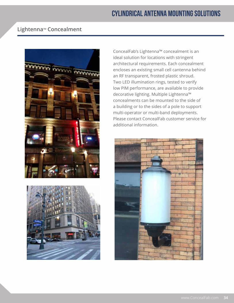
ConcealFab’s Lightenna™ concealment is an ideal solution for locations with stringent architectural requirements. Each concealment encloses an existing small cell cantenna behind an RF transparent, frosted plastic shroud. Two LED illumination rings, tested to verify low PIM performance, are available to provide decorative lighting. Multiple Lightenna™ concealments can be mounted to the side of a building or to the sides of a pole to support multi-operator or multi-band deployments. Please contact ConcealFab customer service for additional information.

35
panel antenna MOUNTING solutions
PRODUCT GUIDE VER. 3
OVERVIEW
Cylindrical antennas are great in terms of size, but limit an operator’s ability to fine tune performance at small cell sites. Panel antennas, on the other hand, provide maximum optimization flexibility at the cost of larger size. With panel antennas, unique coverage scenarios can be achieved by phasing together antennas with different beamwidths at non-120° azimuth spacing. In addition, as new technology becomes available, panel antennas can be easily swapped to expand capability of a site / sector without significantly changing the physical appearance.
To help operators maintain near term and long term flexibility, ConcealFab has developed and continues to expand its portfolio of panel antenna mounting solutions. Standard solutions are currently available for pole tops, pole sides, building walls and signs. Drawing on this experience, ConcealFab can quickly develop customized solutions to meet new operator requirements.
When concealing antennas, it is important to use low loss materials with a low dielectric constant to minimize signal loss and reduce pattern distortion. This becomes increasingly important at frequencies above 2 GHz. For this reason, ConcealFab rarely uses fiberglass as a concealment material. Rather, materials such as ABS and PVC are preferred which provide an optimum combination of outdoor weatherability, structural rigidity and RF properties.

36www.ConcealFab.com
panel antenna MOUNTING solutions
Tri-mast Pole Top Concealment
ConcealFab’s tri-mast pole top concealment provides maximum flexibility for operators deploying multiple panel antennas at small cell / oDAS sites. This 30-inch outside diameter concealment is available in 6-FT and 8-FT lengths. The concealment is large enough to enable +/- 15° independent azimuth adjustment per sector with typical 65° beam width multi-band antennas. This unit can be deployed with a single array of high gain antennas or in a multi-operator configuration with stacked low gain antennas. The tri-mast pole top concealment can be attached to existing poles ranging from 8.25 to 15.75 inch outside diameter or bolted directly to the top new poles. Custom, PIM friendly antenna mounting hardware is available. Please contact ConcealFab customer service for additional information.

37
Single Mast Pole Top Concealment
PANEL ANTENNA mounting SOLUTIONS
PRODUCT GUIDE VER. 3
ConcealFab’s family of single-mast pole top concealments can be easily customized to meet operator requirements. Standard shroud outside diameters include 24, 30 and 36-inch in heights ranging from 3-FT to 8-FT tall. Custom mounting brackets to support ancillary equipment such as diplexers, splitters and grounding bus bars inside the shroud can be provided.
The single-mast pole top concealment can be attached to existing poles ranging from 4.0 to 15.75 inch outside diameter or bolted directly to the top of new poles. Custom antenna mounting hardware is available enabling antennas to be mounted in the smallest diameter shroud possible. Transition shrouds are available to hide the mounting brackets and provide an aesthetically pleasing transition to the pole outside diameter.
Custom antenna brackets
Tri-sector mount

38www.ConcealFab.com
Panel Antenna Side Arm Concealment
PANEL ANTENNA mounting SOLUTIONS
ConcealFab’s panel antenna side arm concealment provides customers the ability to adjust mechanical down tilt and azimuth pointing direction for two back-to-back small cell panel antennas. The concealment is 24-inch diameter x 24-inch tall with an integrated cable concealment shroud for hiding splitters and RF feed-line cabling from public view.
39
Panel Antenna Sign Concealment
PANEL ANTENNA MOUNTING SOLUTIONS
PRODUCT GUIDE VER. 3
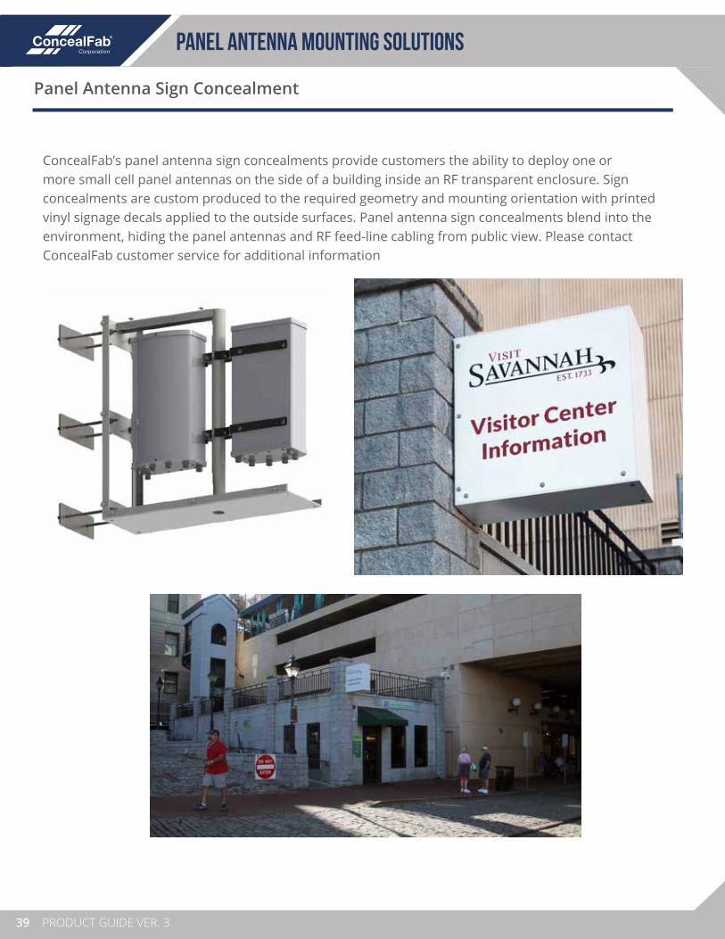
ConcealFab’s panel antenna sign concealments provide customers the ability to deploy one or more small cell panel antennas on the side of a building inside an RF transparent enclosure. Sign concealments are custom produced to the required geometry and mounting orientation with printed vinyl signage decals applied to the outside surfaces. Panel antenna sign concealments blend into the environment, hiding the panel antennas and RF feed-line cabling from public view. Please contact ConcealFab customer service for additional information

40www.ConcealFab.com
Panel Antenna Wall Mount
PANEL ANTENNA mounting SOLUTIONS
PN - PPPPPP-F
AMPHENOL HTXCWW63111414FAMPHENOL HTXCWW4513FAMPHENOL CUUX063X06F
PN - PPPPPP = Base Part #
007314007315007316
F = Finish Code
1 Gray
007315007314 007316
ConcealFab’s panel antenna wall mounting system is designed to mount small cell panel antennas as flush as possible to a building surface. The kit includes a universal mounting frame with custom interface brackets to attach the specific antenna model to the frame. A cable concealment shroud is provided to hide RF feed-line cabling from public view.

41
Stadium / Venue Concealments
PANEL ANTENNA mounting SOLUTIONS
PRODUCT GUIDE VER. 3
Stadiums present an interesting capacity challenge for mobile operators. Even small college university stadiums can seat more than 40,000 fans on game day. Larger stadiums can seat more than 100,000 fans. Designing and optimizing a DAS network that can meet peak data demand while remaining largely out of site is a significant challenge.
ConcealFab has experience deploying custom concealments for venues of all sizes. Our concealments are PIM-free by design and often include custom antenna mounting brackets to achieve the required azimuth and elevation adjustability. Our concealments are structurally rated, including welded steel frames covered by RF transparent materials. Concealments can be painted to match the venue color or covered with vinyl graphic signage with team logos and seating section identification.

2www.ConcealFab.com
rf optimization products
OVERVIEW
The key to optimizing LTE network performance is maximizing the Signal-to-Interference-plus-Noise-Ratio (SINR). When the signal level is strong and the noise level is low, LTE networks can evoke higher order modulation schemes to increase data throughput. One could argue that all ConcealFab products are RF optimization solutions since small cell / oDAS concealments help operators achieve site approval at the best possible locations, maximizing the “signal” side of the equation. However, in this section we will highlight ConcealFab products that minimize the “noise” side of the equation. These include back lobe suppressors as well as passive intermodulation (PIM) mitigation solutions.
42www.ConcealFab.com
PIM mitigation on rooftop
Backlobe Suppressors
Antenna Test Chamber

43
Passive Intermodulation (PIM) Mitigation
RF OPTIMIZATION PRODUCTS
PRODUCT GUIDE VER. 3
OVERVIEW
Passive intermodulation (PIM) is a well-known problem in cellular systems. Downlink signals at the cell site mix at passive, non-linear junctions in the RF path, creating new signals. If these new signals (intermodulation products) fall in an operator’s uplink band, they can elevate the noise floor and degrade system performance.
RF equipment manufacturers have spent decades developing methods to improve the PIM performance of the RF components deployed at cell sites. In addition, the crews installing these components have fine-tuned their skills to the point that PIM levels below -150 dBc (with 20W test tones) are now readily achievable within antenna feed systems. Unfortunately, a low PIM feed system by itself doesn’t insure that a site will perform to expectations. PIM sources beyond the antenna are now often the limiting factor for site PIM performance.
ConcealFab is a leader in the wireless industry in developing solutions to mitigate external passive intermodulation. ConcealFab began by developing its proprietary PIM Kote™ finish to reduce PIM at metal-to-metal contacts in the antenna mounting system and later developed our PIM Shield™ line to suppress radiation of near field PIM sources in small cell installations. ConcealFab is expanding the PIM Shield™ family of products to rooftop as well as tower top applications by developing a portfolio of temporary and permanent solutions for mitigating external PIM at cell sites.
Network operators need to be very careful when selecting mounting and concealment solutions for small cell antennas. Even when located behind or below the antenna, these products fall in the antenna’s near field where PIM performance is critical. ConcealFab’s proprietary PIM Kote™ finish was developed to not only enhance site aesthetics but also insure low PIM performance. PIM Kote™ is factory applied to ConcealFab’s antenna mounting solutions and is available in four standard colors (Black, Brown, Gray and Silver).
PIM Kote™ Finish

44www.ConcealFab.com
PIM Shield™
RF OPTIMIZATION PRODUCTS
PIM Blanket™
PIM Shield™ is a family of RF optimization products developed to greatly reduce external PIM at cell sites. PIM Shield™ creates a barrier to prevent radiated energy from the antenna from reaching external PIM sources. PIM Shields™ are available that attach directly to antennas to suppress near field PIM sources above, below and behind the antenna. Products are also available for rooftop applications to suppress PIM sources in front of the antenna. For more information, please contact ConcealFab customer service.
ConcealFab’s PIM Blanket™ is a temporary RF barrier that can be deployed on rooftops, both in front of as well as behind base station antennas to help isolate sources of Passive intermodulation (PIM). When a PIM blanket is placed over an external PIM source, PIM from that source reduces by >30 dB. PIM blankets not only help validate the exact location of external PIM but also show the level of improvement that could be achieved with a permanent repair. Reference Anritsu application note 11410-00992A, Identifying Sources of External PIM for additional information.
ConcealFab’s PIM blanket is designed for field use and will resist punctures and tears when dragged across abrasive roofing materials. Tie-down points are provided at each corner to help secure the blanket in windy test conditions. A variety of standard sizes are available to support different test scenarios.
PN - 000000
Part Number Length Width
007640-120060
007640-060060
007640-060030
007640-030030
120 inch
60 inch
60 inch
30 inch
60 inch
60 inch
30 inch
30 inch

45
Back Lobe Suppression
RF OPTIMIZATION PRODUCTS
PRODUCT GUIDE VER. 3
OVERVIEW
In a perfect LTE system, each mobile device in a sector would only receive a strong signal from the base station antenna designated to serve that sector. The signal from one sector should be dominant all the way to the edge of coverage, then rapidly decay as the user moves across the sector boundary. In the real world, this is very difficult to achieve. In many cases signals from adjacent or even distant sectors can arrive stronger than desired within the coverage area creating interference and causing unwanted hand-offs. This is particularly challenging in stadium applications which may include more than 50 sectors within and around a single venue.
Engineers designing a cellular system use directional base station antennas to focus energy into the desired area of coverage. An ideal base station antenna would only radiate energy where intended and not radiate energy in unwanted directions. Unfortunately, that is not possible (or practical) given the size and cost constraints placed on base station antenna manufacturers. Unwanted side and back lobe radiation often occurs at lower frequencies where the physical size of the antenna is small with respect to a wavelength.
To combat undesired back lobe radiation, ConcealFab has developed surface wave suppression technology that can be applied to existing base station antennas. The suppressors are built onto an aluminum frame and coated with polyurethane (truck bed liner) for environmental protection. Hardware is provided to attach the suppressor between the antenna and its existing pole mounting bracket. Due to size and physical mounting differences, a unique back lobe suppressor design is required for each different antenna model.
46www.ConcealFab.com
Back Lobe Suppressors
RF OPTIMIZATION PRODUCTS
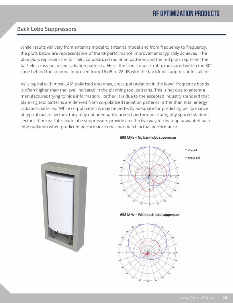
While results will vary from antenna model to antenna model and from frequency to frequency, the plots below are representative of the RF performance improvements typically achieved. The blue plots represent the far field, co-polarized radiation patterns and the red plots represent the far field, cross-polarized radiation patterns. Here, the front-to-back ratio, measured within the 30° cone behind the antenna improved from 16 dB to 28 dB with the back lobe suppressor installed.
As is typical with most ±45° polarized antennas, cross-pol radiation in the lower frequency bands is often higher than the level indicated in the planning tool patterns. This is not due to antenna manufactures trying to hide information. Rather, it is due to the accepted industry standard that planning tool patterns are derived from co-polarized radiation patterns rather than total energy radiation patterns. While co-pol patterns may be perfectly adequate for predicting performance at typical macro sectors, they may not adequately predict performance at tightly spaced stadium sectors. ConcealFab’s back lobe suppressors provide an effective way to clean-up unwanted back lobe radiation when predicted performance does not match actual performance.

notes:
47

sales contactConcealFab is working with two of the largest Manufacturing Representative firms in the country in order to have a local presence in major metropolitan areas. EPIC Marketing and Precision Marketing give ConcealFab continuous coverage in 39 states. Their knowledge of RF products in general and our products specifically, coupled with their Carrier and non-carrier relationships creates a powerful local support team for ConcealFab. In addition, our reps have extensive PIM, fiber, and power expertise.
Regional Manufacturing Representatives
48www.ConcealFab.com
Epic MarketingAK, WA, HI, OR, CA, NV
Epic Marketing Contact: [email protected]
Precision Marketing Inc.AL, CT, FL, DE, GA, IA, IL, KY, KS, MA, MI, MD, ME, MN, MO, MS, NH, ND, NE, NJ, NC, NY, PA, SC, SD, TN, RI, VA, VT, DC, WI, WV, IN, OH
Precision Marketing Contact:[email protected]

HIDE IN PLAIN SIGHT®
Small Cell & DAS Solutions for all Concealment Levels
PRODUCT GUIDE I VERSION 3.1 I APRIL 2017
719-599-3400
www.ConcealFab.com
3525 N. Cascade Avenue
Colorado Springs, Colorado 80907
PRO
DU
CT G
UID
E I
VE
RSIO
N 3
I
201
7