hierarchical model - db-book.com · appendix e hierarchical model in the network model, the data...
TRANSCRIPT

A P P E N D I X EHierarchical Model
In the network model, the data are represented by collections of records andrelationships between data are represented by links. This structure holds for thehierarchical model as well. The only difference is that, in the hierarchical model,records are organized as collections of trees, rather than as arbitrary graphs.
In this chapter we illustrate our concepts using a bank enterprise with theschema shown in Figure 2.15.
E.1 Basic Concepts
A hierarchical database consists of a collection of records that are connected toeach other through links. A record is similar to a record in the network model.Each record is a collection of fields (attributes), each of which contains only onedata value. A link is an association between precisely two records. Thus, a linkhere is similar to a link in the network model.
Consider a database that represents a customer-account relationship in a bank-ing system. There are two record types: customer and account. The customerrecord type can be defined in the same manner as in Appendix A. It consistsof three fields: customer name, customer street, and customer city. Similarly, the ac-count record consists of two fields: account number and balance.
A sample database appears in Figure E.1. It shows that customer Hayes hasaccount A-102, customer Johnson has accounts A-101 and A-201, and customerTurner has account A-305.
Note that the set of all customer and account records is organized in the formof a rooted tree, where the root of the tree is a dummy node. As we shall see, ahierarchical database is a collection of such rooted trees, and hence forms a forest.We shall refer to each such rooted tree as a database tree.
The content of a particular record may have to be replicated in several differentlocations. For example, in our customer-account banking system, an accountmay belong to several customers. The information pertaining to that account,or the information pertaining to the various customers to which that accountmay belong, will have to be replicated. This replication may occur either in the
1

2 Appendix E Hierarchical Model
Figure E.1 Sample database.
same database tree or in several different trees. Record replication has two majordrawbacks:
1. Data inconsistency may result when updating takes place.
2. Waste of space is unavoidable.
We shall deal with this issue in Section E.5 by introducing the concept of a virtualrecord.
E.2 Tree-Structure Diagrams
A tree-structure diagram is the schema for a hierarchical database. Such a diagramconsists of two basic components:
1. Boxes, which correspond to record types
2. Lines, which correspond to links
A tree-structure diagram serves the same purpose as an entity–relationship (E-R)diagram; namely, it specifies the overall logical structure of the database. A tree-structure diagram is similar to a data-structure diagram in the network model.The main difference is that, in the latter, record types are organized in the form ofan arbitrary graph, whereas in the former, record types are organized in the formof a rooted tree.
We have to be more precise about what a rooted tree is. First, there can be nocycles in the underlying graph. Second, there is a record type that is designated asthe root of the tree. The relationships formed in the tree-structure diagram mustbe such that only one-to-many or one-to-one relationships exist between a parentand a child. The general form of a tree-structure diagram appears in Figure E.2.Note that the arrows are pointing from children to parents. A parent may have anarrow pointing to a child, but a child must have an arrow pointing to its parent.
The database schema is represented as a collection of tree-structure diagrams.For each such diagram, there exists one single instance of a database tree. The rootof this tree is a dummy node. The children of the dummy node are instances of the

E.2 Tree-Structure Diagrams 3
Figure E.2 General structure of a tree-structure diagram.
root record type in the tree-structure diagram. Each record instance may, in turn,have several children, which are instances of various record types, as specified inthe corresponding tree-structure diagram.
To understand how tree-structure diagrams are formed, we shall show how totransform E-R diagrams to their corresponding tree-structure diagrams. We firstshow how to apply such transformations to single relationships. We then explainhow to ensure that the resulting diagrams are in the form of rooted trees.
E.2.1 Single Relationships
Consider the E-R diagram of Figure E.3a; it consists of the two entity sets customerand account related through a binary, one-to-many relationship depositor, withno descriptive attributes. This diagram specifies that a customer can have severalaccounts, but an account can belong to only one customer. The corresponding tree-structure diagram appears in Figure E.3b. The record type customer corresponds to
Figure E.3 E-R diagram and its corresponding tree-structure diagram.

4 Appendix E Hierarchical Model
Figure E.4 Tree-structure diagram with one-to-one relationship.
the entity set customer. It includes three fields: customer name, customer street, andcustomer city. Similarly, account is the record type corresponding to the entity setaccount. It includes two fields: account number and balance. Finally, the relationshipdepositor has been replaced with the link depositor, with an arrow pointing tocustomer record type.
An instance of a database corresponding to the described schema may thuscontain a number of customer records linked to a number of account records, asin Figure E.1. Since the relationship is one to many from customer to account,a customer can have more than one account, as does Johnson, who has bothaccounts A-101 and A-201. An account, however, cannot belong to more than onecustomer; none do in the sample database.
If the relationship depositor is one to one, then the link depositor has twoarrows: one pointing to account record type, and one pointing to customer recordtype (Figure E.4). A sample database corresponding to this schema appears inFigure E.5. Since the relationship is one to one, an account can be owned byprecisely one customer, and a customer can have only one account, as is indeedthe case in the sample database.
If the relationship depositor is many to many (see Figure E.6a), then the trans-formation from an E-R diagram to a tree-structure diagram is more complicated.Only one-to-many and one-to-one relationships can be directly represented in thehierarchical model.
There are many different ways to transform this E-R diagram to a tree-structurediagram. All these diagrams, however, share the property that the underlyingdatabase tree (or trees) will have replicated records.
Figure E.5 Sample database corresponding to diagram of Figure E.4.

E.2 Tree-Structure Diagrams 5
Figure E.6 E-R diagram and its corresponding tree-structure diagrams.
The decision regarding which transformation should be used depends onmany factors, including
• The type of queries expected on the database
• The degree to which the overall database schema being modeled fits the givenE-R diagram
We shall present a transformation that is as general as possible. That is, all otherpossible transformations are a special case of this one transformation.
To transform the E-R diagram of Figure E.6a into a tree-structure diagram, wetake these steps:
1. Create two separate tree-structure diagrams, T1 and T2, each of which hasthe customer and account record types. In tree T1, customer is the root; in treeT2, account is the root.
2. Create the following two links:
• depositor, a many-to-one link from account record type to customer recordtype, in T1
• account customer, a many-to-one link from customer record type to ac-count record type, in T2
The resulting tree-structure diagrams appear in Figure E.6b. The presence of twodiagrams (1) permits customers who do not participate in the depositor relation-ship as well as accounts that do not participate in the depositor relationship, and(2) permits efficient access to account information for a given customer as well ascustomer information for a given account.
6 Appendix E Hierarchical Model
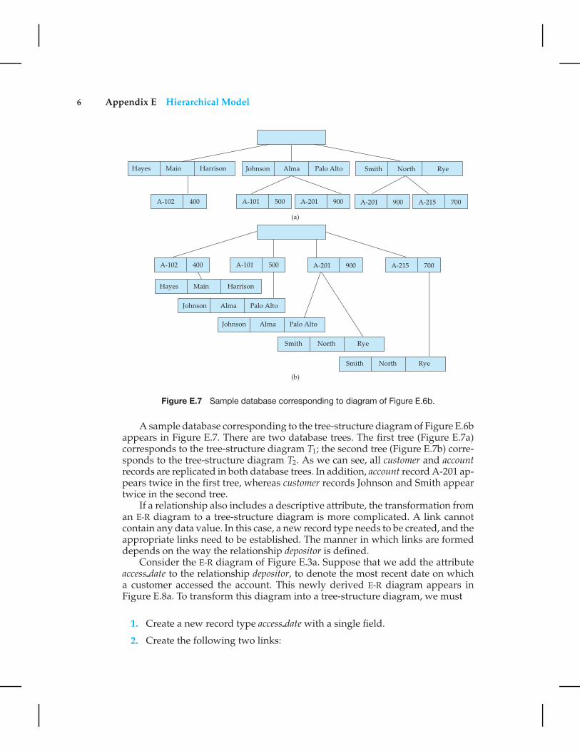
Figure E.7 Sample database corresponding to diagram of Figure E.6b.
A sample database corresponding to the tree-structure diagram of Figure E.6bappears in Figure E.7. There are two database trees. The first tree (Figure E.7a)corresponds to the tree-structure diagram T1; the second tree (Figure E.7b) corre-sponds to the tree-structure diagram T2. As we can see, all customer and accountrecords are replicated in both database trees. In addition, account record A-201 ap-pears twice in the first tree, whereas customer records Johnson and Smith appeartwice in the second tree.
If a relationship also includes a descriptive attribute, the transformation froman E-R diagram to a tree-structure diagram is more complicated. A link cannotcontain any data value. In this case, a new record type needs to be created, and theappropriate links need to be established. The manner in which links are formeddepends on the way the relationship depositor is defined.
Consider the E-R diagram of Figure E.3a. Suppose that we add the attributeaccess date to the relationship depositor, to denote the most recent date on whicha customer accessed the account. This newly derived E-R diagram appears inFigure E.8a. To transform this diagram into a tree-structure diagram, we must
1. Create a new record type access date with a single field.
2. Create the following two links:

E.2 Tree-Structure Diagrams 7
Figure E.8 E-R diagram and its corresponding tree-structure diagram.
• customer date, a many-to-one link from access date record type to customerrecord type
• date account, a many-to-one link from account record type to access daterecord type
Figure E.9 Sample database corresponding to diagram of Figure E.8b.

8 Appendix E Hierarchical Model
Figure E.10 Tree-structure diagram with many-to-many relationships.
The resulting tree-structure diagram is illustrated in Figure E.8b.An instance corresponding to the described schema appears in Figure E.9. It
shows that:
• Hayes has account A-102, which was last accessed on 10 June 2009.
• Johnson has two accounts: A-101, which was last accessed on 24 May 2009,and A-201, which was last accessed on 17 June 2009.
Figure E.11 Sample database corresponding to diagram of Figure E.10.

E.2 Tree-Structure Diagrams 9
• Turner has account A-305, which was last accessed on 10 June 2009.
Note that two different accounts can be accessed on the same date, as wereaccounts A-102 and A-305. These accounts belong to two different customers, sothe access date record must be replicated to preserve the hierarchy.
If the relationship depositor were one to one with the attribute date, thenthe transformation algorithm would be similar to the one described. The onlydifference would be that the two links customer date and date account would beone-to-one links.
Assume that the relationship depositor is many to many with the attributeaccess date; here again, we can choose among a number of alternative transfor-mations. We shall use the most general transformation; it is similar to the oneapplied to the case where the relationship depositor has no descriptive attribute.The record types customer, account, and access date need to be replicated, and twoseparate tree-structure diagrams must be created, as in Figure E.10. A sampledatabase corresponding to this schema is in Figure E.11.
Until now, we have considered only binary relationships. We shift our at-tention here to general relationships. The transformation of E-R diagrams cor-responding to general relationships into tree-structure diagrams is complicated.
Figure E.12 E-R diagram and its corresponding tree-structure diagrams.
10 Appendix E Hierarchical Model
Rather than present a general transformation algorithm, we present a single ex-ample to illustrate the overall strategy that you can apply to deal with such atransformation.
Consider the E-R diagram of Figure E.12a, which consists of the three entitysets customer, account, and branch, related through the general relationship setCAB with no descriptive attribute.
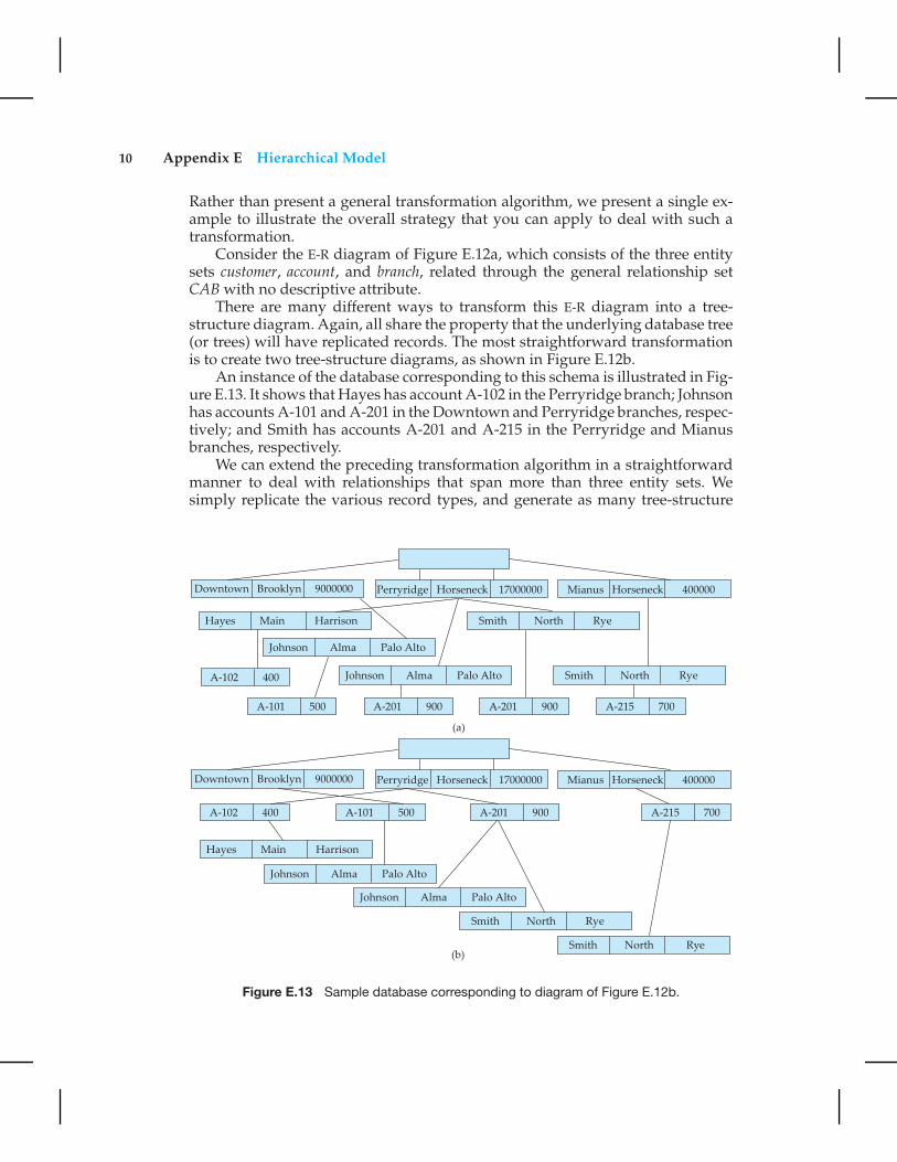
There are many different ways to transform this E-R diagram into a tree-structure diagram. Again, all share the property that the underlying database tree(or trees) will have replicated records. The most straightforward transformationis to create two tree-structure diagrams, as shown in Figure E.12b.
An instance of the database corresponding to this schema is illustrated in Fig-ure E.13. It shows that Hayes has account A-102 in the Perryridge branch; Johnsonhas accounts A-101 and A-201 in the Downtown and Perryridge branches, respec-tively; and Smith has accounts A-201 and A-215 in the Perryridge and Mianusbranches, respectively.
We can extend the preceding transformation algorithm in a straightforwardmanner to deal with relationships that span more than three entity sets. Wesimply replicate the various record types, and generate as many tree-structure
Figure E.13 Sample database corresponding to diagram of Figure E.12b.

E.2 Tree-Structure Diagrams 11
Figure E.14 E-R diagram and its transformation.
diagrams as necessary. We can extend this approach, in turn, to deal with ageneral relationship that has descriptive attributes. We need only to create a newrecord type with one field for each descriptive attribute, and then to insert thatrecord type in the appropriate location in the tree-structure diagram.
E.2.2 Several Relationships
The scheme that we have described to transform an E-R diagram to a tree-structurediagram ensures that, for each single relationship, the transformation will resultin diagrams that are of the form of rooted trees. Unfortunately, application ofsuch a transformation individually to each relationship in an E-R diagram doesnot necessarily result in diagrams that are rooted trees.
Next, we shall discuss means for resolving the problem. The technique is tosplit the diagrams in question into several diagrams, each of which is a rooted tree.We present here two examples to illustrate the overall strategy that you can applyto deal with such transformations. (The large number of different possibilitieswould make it cumbersome to present a general transformation algorithm.)
Consider the E-R diagram of Figure E.14a. By applying the transformationalgorithm in Section E.2.1 separately to the relationships account-branch and de-positor, we obtain the diagram of Figure E.14b. This diagram is not a rooted tree,
Figure E.15 Tree-structure diagram corresponding to Figure E.14a.
12 Appendix E Hierarchical Model
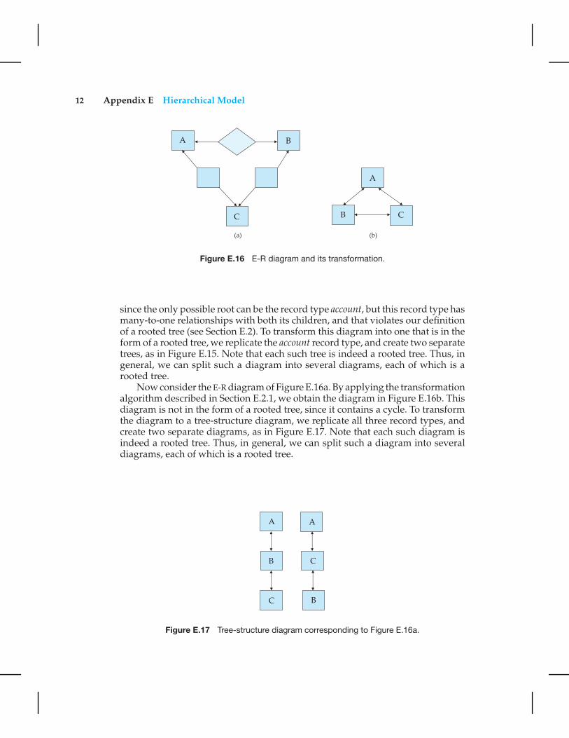
Figure E.16 E-R diagram and its transformation.
since the only possible root can be the record type account, but this record type hasmany-to-one relationships with both its children, and that violates our definitionof a rooted tree (see Section E.2). To transform this diagram into one that is in theform of a rooted tree, we replicate the account record type, and create two separatetrees, as in Figure E.15. Note that each such tree is indeed a rooted tree. Thus, ingeneral, we can split such a diagram into several diagrams, each of which is arooted tree.
Now consider the E-R diagram of Figure E.16a. By applying the transformationalgorithm described in Section E.2.1, we obtain the diagram in Figure E.16b. Thisdiagram is not in the form of a rooted tree, since it contains a cycle. To transformthe diagram to a tree-structure diagram, we replicate all three record types, andcreate two separate diagrams, as in Figure E.17. Note that each such diagram isindeed a rooted tree. Thus, in general, we can split such a diagram into severaldiagrams, each of which is a rooted tree.
Figure E.17 Tree-structure diagram corresponding to Figure E.16a.
E.3 Data-Retrieval Facility 13
Figure E.18 Tree-structure diagram.
E.3 Data-Retrieval Facility
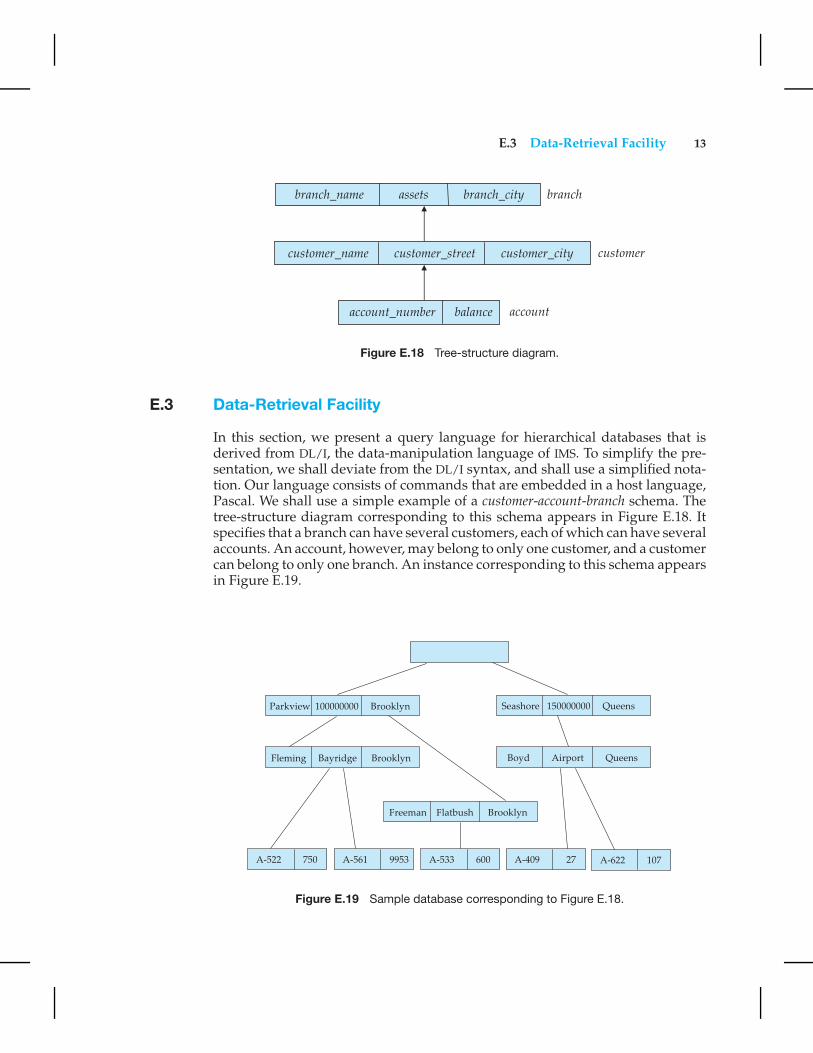
In this section, we present a query language for hierarchical databases that isderived from DL/I, the data-manipulation language of IMS. To simplify the pre-sentation, we shall deviate from the DL/I syntax, and shall use a simplified nota-tion. Our language consists of commands that are embedded in a host language,Pascal. We shall use a simple example of a customer-account-branch schema. Thetree-structure diagram corresponding to this schema appears in Figure E.18. Itspecifies that a branch can have several customers, each of which can have severalaccounts. An account, however, may belong to only one customer, and a customercan belong to only one branch. An instance corresponding to this schema appearsin Figure E.19.
Figure E.19 Sample database corresponding to Figure E.18.

14 Appendix E Hierarchical Model
E.3.1 Program Work Area
Each application program executing in the system consists of a sequence of state-ments. Some of these statements are in Pascal; others are data-manipulation-language command statements. These statements access and manipulate databaseitems, as well as locally declared variables. For each such application program, thesystem maintains a program work area, which is a buffer storage area that containsthe following variables:
• Record templates. A record (in the Pascal sense) for each record type accessedby the application program
• Currency pointers. A set of pointers, one for each database tree, containingthe address of the record in that particular tree (regardless of type) mostrecently accessed by the application program
• Status flag. A variable set by the system to indicate to the application programthe outcome of the most recent database operation; we call this flag DB-statusand use the same convention as in the DBTG model to denote failure—namely,if DB-status = 0, then the most recent operation succeeded.
We reemphasize that a particular program work area is associated with preciselyone application program.
For our branch-customer-account example, a particular program work areacontains the following:
• Templates. One record for each of three record types:
◦ branch record
◦ customer record
◦ account record
• Currency pointer. A pointer to the most recently accessed record of branch,customer, or account type
• Status. One status variable
E.3.2 The get Command
Data are retrieved through the get command. The actions taken in response to aget are as follows:
1. Locate a record in the database and set the currency pointer to it.
2. Copy that record from the database to the appropriate program area tem-plate.

E.3 Data-Retrieval Facility 15
The get command must specify which of the database trees is to be searched. Forour example, we assume that the only database tree to be searched is the sampledatabase of Figure E.19; thus, we omit this specification in our queries.
As an illustration of the general effect that the get command has on theprogram work area, consider the sample database of Figure E.19. Suppose thata get command is issued to locate the customer record belonging to Freeman.Once this command executes successfully, these changes occur in the state of theprogram work area:
• The currency pointer points now to the record of Freeman.
• The information pertaining to Freeman is copied into the customer recordwork-area template.
• DB-status is set to the value 0.
To scan all records in a consistent manner, we must impose an ordering on therecords. The one commonly used is preorder. A preorder search starts at the root,and then searches the subtrees of the root from left to right, recursively. Thus, westart at the root, visit the leftmost child, visit its leftmost child, and so on, until wereach a leaf (childless) node. We then move back to the parent of the leaf and visitthe leftmost unvisited child. We proceed in this manner until we have visited theentire tree. For example, the preordered listing of the records in the database treeof Figure E.19 is:
Parkview, Fleming, A-522, A-561, Freeman, A-533,Seashore, Boyd, A-409, A-622
E.3.3 Access within a Database Tree
There are two different get commands for locating records in a database tree. Thesimplest command has the form
get first <record type>
where <condition>
The where clause is optional. The attached <condition> is a predicate that mayinvolve any record type that is either an ancestor of <record type> or the <recordtype> itself.
The get command locates the first record (in preorder) of type <record type>
in the database that satisfies the <condition> of the where clause. If the whereclause is omitted, then the command locates the first record of type <record-type>. Once such a record is found, the currency pointer is set to point to thatrecord, and the content of the record is copied into the appropriate work-areatemplate. If no such record exists in the database tree, then the search fails, andthe variable DB-status is set to an appropriate error message.
16 Appendix E Hierarchical Model
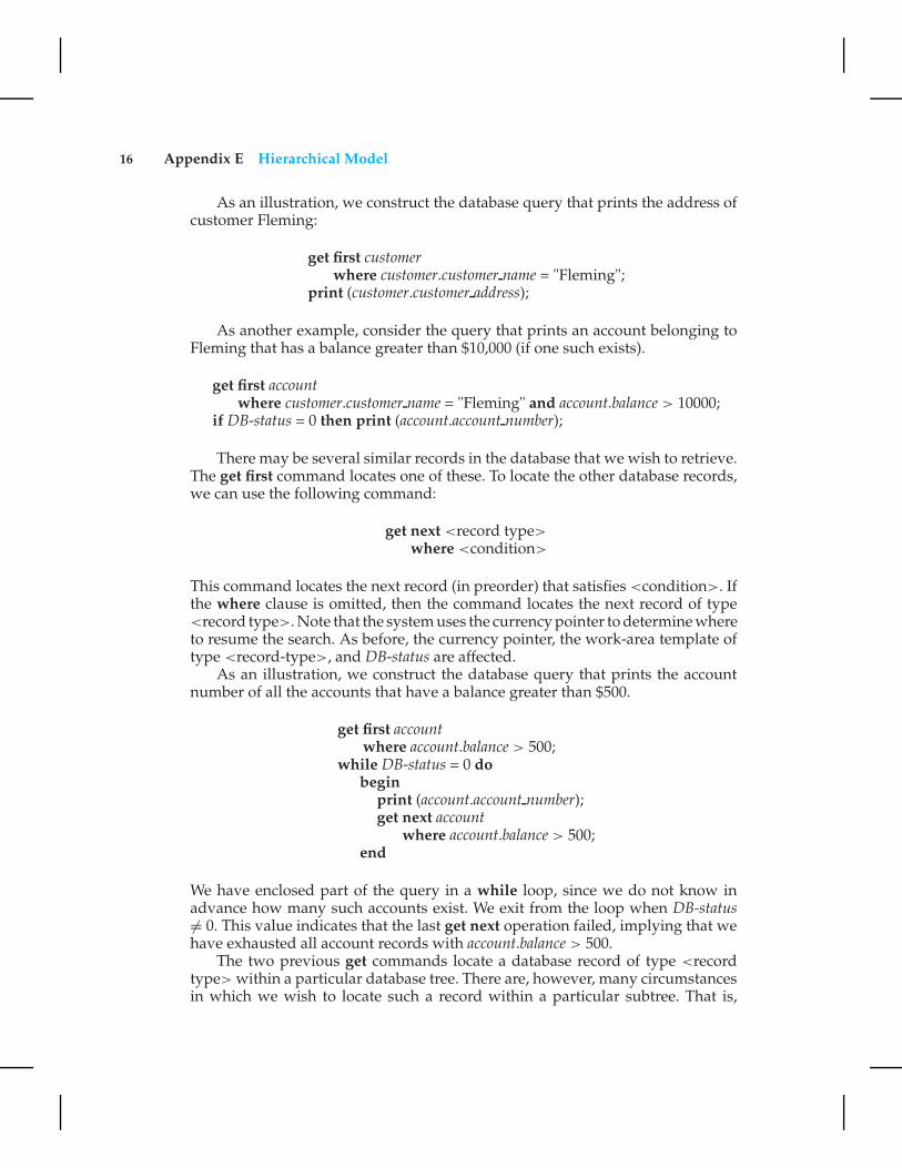
As an illustration, we construct the database query that prints the address ofcustomer Fleming:
get first customerwhere customer.customer name = "Fleming";
print (customer.customer address);
As another example, consider the query that prints an account belonging toFleming that has a balance greater than $10,000 (if one such exists).
get first accountwhere customer.customer name = "Fleming" and account.balance > 10000;
if DB-status = 0 then print (account.account number);
There may be several similar records in the database that we wish to retrieve.The get first command locates one of these. To locate the other database records,we can use the following command:
get next <record type>
where <condition>
This command locates the next record (in preorder) that satisfies <condition>. Ifthe where clause is omitted, then the command locates the next record of type<record type>. Note that the system uses the currency pointer to determine whereto resume the search. As before, the currency pointer, the work-area template oftype <record-type>, and DB-status are affected.
As an illustration, we construct the database query that prints the accountnumber of all the accounts that have a balance greater than $500.
get first accountwhere account.balance > 500;
while DB-status = 0 dobegin
print (account.account number);get next account
where account.balance > 500;end
We have enclosed part of the query in a while loop, since we do not know inadvance how many such accounts exist. We exit from the loop when DB-status�= 0. This value indicates that the last get next operation failed, implying that wehave exhausted all account records with account.balance > 500.
The two previous get commands locate a database record of type <recordtype> within a particular database tree. There are, however, many circumstancesin which we wish to locate such a record within a particular subtree. That is,

E.4 Update Facility 17
we want to limit the search to one specific subtree, rather than search the entiredatabase tree. The root of the subtree in question is the most recent record thatwas located with either a get first or get next command. This record is known asthe current parent. There is only one current parent record per database tree. Theget command to locate a record within the subtree rooted at the current parenthas the form
get next within parent <record type>
where <condition>
It locates the next record (in preorder) of type <record type> that satisfies<condition> and is in the subtree rooted at the current parent. If the whereclause is omitted, then the command locates the next record of type <recordtype> within the designated subtree. The system uses the currency pointer todetermine where to resume the search. As before, the currency pointer and thework-area template of type <record type> are affected. In this case, however,the DB-status is set to a nonzero value if no such record exists in the designatedsubtree, rather than if none exists in the entire tree. Note that a get next withinparent command will not modify the pointer to the current parent.
To illustrate how this get command executes, we shall construct the querythat prints the total balance of all accounts belonging to Boyd:
sum := 0;get first customer
where customer.customer name = "Boyd";get next within parent account;while DB-status = 0 do
beginsum := sum + account.balance;get next within parent account;
endprint (sum);
Note that we exit from the while loop and print out the value of sum only whenthe DB-status is set to a value not equal to 0. Such a value exists after the get nextwithin parent operation fails, indicating that we have exhausted all the accountswhose owner is customer Boyd.
E.4 Update Facility
Section E.3 described commands for querying the database. In this section, wedescribe the mechanisms available for updating information in the database. Theyallow insertion and deletion of records, as well as modification of the content ofexisting records.

18 Appendix E Hierarchical Model
E.4.1 Creation of New Records
To insert a record of type <record type> into the database, we must first setthe appropriate values in the corresponding <record type> work-area template.Once we set them, we add the new record to the database tree by executing
insert <record type>
where <condition>
If the where clause is included, the system searches the database tree (inpreorder) for a record that satisfies the <condition> in the where clause. Onceit finds such a record—say, X—it inserts the newly created record into the treeas the leftmost child of X. If the where clause is omitted, the system inserts therecord in the first position (in preorder) in the database tree where a record type<record type> can be inserted in accordance with the schema specified by thecorresponding tree-structure diagram.
Consider the program for adding a new customer, Jackson, to the Seashorebranch:
customer.customer name := "Jackson";customer.customer street := "Old Road";customer.customer city := "Queens";insert customer
where branch.branch name = "Seashore";
The result of executing this program is the database tree of Figure E.20.As another example, consider the program for creating a new account num-
bered A-655 that belongs to customer “Jackson”:
account.account number := "A-655";account.balance := 100;insert account
where customer.customer name = "Jackson";
The result of executing this program is the database tree of Figure E.21.
E.4.2 Modification of an Existing Record
To modify an existing record of type <record type>, we must get that record intothe work-area template for <record type>, and change the desired fields in thattemplate. Then, we reflect the changes in the database by executing
replace

E.4 Update Facility 19
Figure E.20 New database tree.
Note that the replace command does not have <record type> as an argument.The record that is affected is the one to which the currency pointer points, whichmust be the desired record.
Figure E.21 New database tree.
20 Appendix E Hierarchical Model
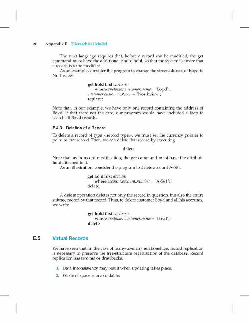
The DL/I language requires that, before a record can be modified, the getcommand must have the additional clause hold, so that the system is aware thata record is to be modified.
As an example, consider the program to change the street address of Boyd toNorthview:
get hold first customerwhere customer.customer name = "Boyd";
customer.customer street := "Northview";replace;
Note that, in our example, we have only one record containing the address ofBoyd. If that were not the case, our program would have included a loop tosearch all Boyd records.
E.4.3 Deletion of a Record
To delete a record of type <record type>, we must set the currency pointer topoint to that record. Then, we can delete that record by executing
delete
Note that, as in record modification, the get command must have the attributehold attached to it.
As an illustration, consider the program to delete account A-561:
get hold first accountwhere account.account number = "A-561";
delete;
A delete operation deletes not only the record in question, but also the entiresubtree rooted by that record. Thus, to delete customer Boyd and all his accounts,we write
get hold first customerwhere customer.customer name = "Boyd";
delete;
E.5 Virtual Records
We have seen that, in the case of many-to-many relationships, record replicationis necessary to preserve the tree-structure organization of the database. Recordreplication has two major drawbacks:
1. Data inconsistency may result when updating takes place.
2. Waste of space is unavoidable.

E.5 Virtual Records 21
Figure E.22 Tree-structure diagram with virtual records.
There are several ways to eliminate these drawbacks.To eliminate record replication, we need to relax our requirement that the
logical organization of data be constrained to a tree structure. We need to do thatcautiously, however, since otherwise we will end up with the network model.
The solution is to introduce the concept of a virtual record. Such a recordcontains no data value; it does contain a logical pointer to a particular physicalrecord. Instead of replication, we keep a single copy of the physical record, andeverywhere else we keep virtual records containing a pointer to that physicalrecord.
More specifically, we let R be a record type that is replicated in several tree-structure diagrams—say, T1, T2, · · · , Tn. To eliminate replication, we create a newvirtual record type virtual-R, and replace R in each of the n − 1 trees with a recordof type virtual-R.
Figure E.23 Sample database corresponding to diagram of Figure E.22.
22 Appendix E Hierarchical Model
As an example, consider the E-R diagram of Figure E.6a and its correspondingtree-structure diagram, which comprises two separate trees, each consisting ofboth customer and account record types (Figure E.6b).
To eliminate data replication, we create two virtual record types: virtualcustomer and virtual account. We then replace record type account with record
type virtual account in the first tree, and replace record type customer with recordtype virtual customer in the second tree. We also add a dashed line from virtualcustomer record to customer record, and a dashed line from virtual account record
to account record, to specify the association between a virtual record and itscorresponding physical record. The resulting tree-structure diagram appears inFigure E.22.
A sample database corresponding to the diagram of Figure E.22 appears inFigure E.23. Note that only a single copy of the information for each customer andeach account exists. Contrast this database with the same information depictedin Figure E.7, where replication is allowed.
The data-manipulation language for this new configuration remains the sameas in the case where record replication is allowed. Thus, a user does not need tobe aware of these changes. Only the internal implementation is affected.
E.6 Mapping of Hierarchies to Files
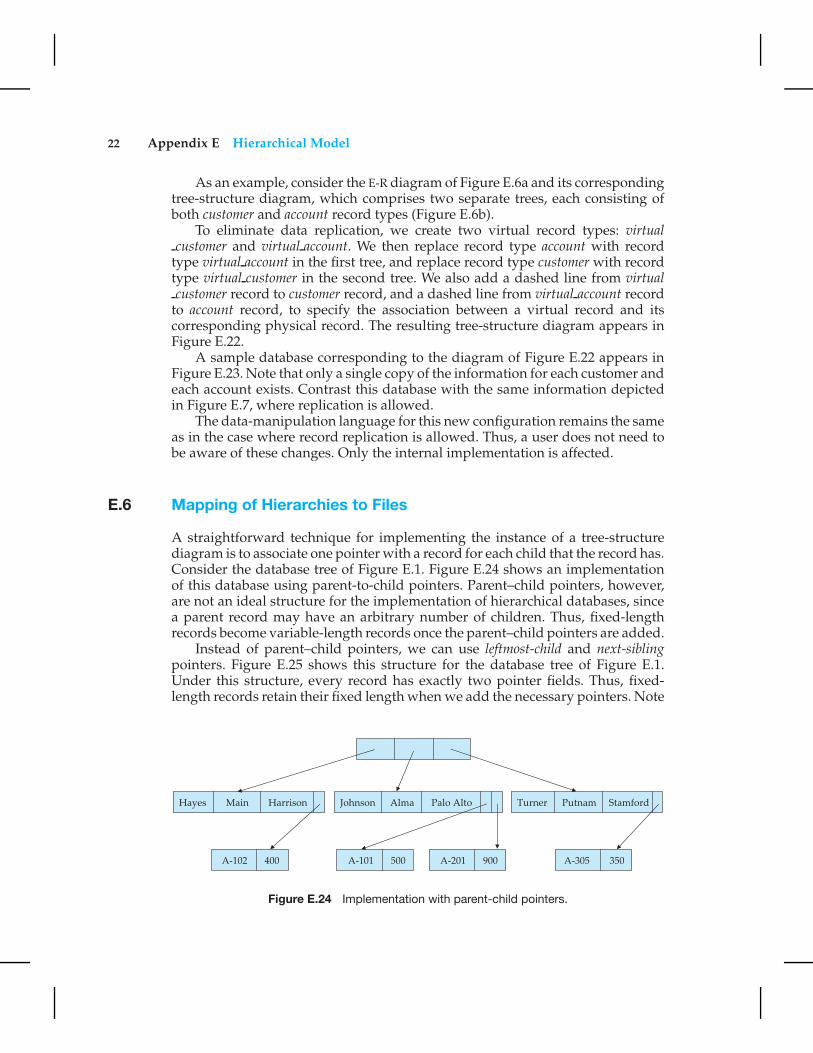
A straightforward technique for implementing the instance of a tree-structurediagram is to associate one pointer with a record for each child that the record has.Consider the database tree of Figure E.1. Figure E.24 shows an implementationof this database using parent-to-child pointers. Parent–child pointers, however,are not an ideal structure for the implementation of hierarchical databases, sincea parent record may have an arbitrary number of children. Thus, fixed-lengthrecords become variable-length records once the parent–child pointers are added.
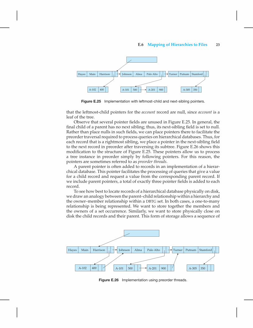
Instead of parent–child pointers, we can use leftmost-child and next-siblingpointers. Figure E.25 shows this structure for the database tree of Figure E.1.Under this structure, every record has exactly two pointer fields. Thus, fixed-length records retain their fixed length when we add the necessary pointers. Note
Figure E.24 Implementation with parent-child pointers.
E.6 Mapping of Hierarchies to Files 23
Figure E.25 Implementation with leftmost-child and next-sibling pointers.
that the leftmost-child pointers for the account record are null, since account is aleaf of the tree.
Observe that several pointer fields are unused in Figure E.25. In general, thefinal child of a parent has no next sibling; thus, its next-sibling field is set to null.Rather than place nulls in such fields, we can place pointers there to facilitate thepreorder traversal required to process queries on hierarchical databases. Thus, foreach record that is a rightmost sibling, we place a pointer in the next-sibling fieldto the next record in preorder after traversing its subtree. Figure E.26 shows thismodification to the structure of Figure E.25. These pointers allow us to processa tree instance in preorder simply by following pointers. For this reason, thepointers are sometimes referred to as preorder threads.
A parent pointer is often added to records in an implementation of a hierar-chical database. This pointer facilitates the processing of queries that give a valuefor a child record and request a value from the corresponding parent record. Ifwe include parent pointers, a total of exactly three pointer fields is added to eachrecord.
To see how best to locate records of a hierarchical database physically on disk,we draw an analogy between the parent–child relationship within a hierarchy andthe owner–member relationship within a DBTG set. In both cases, a one-to-manyrelationship is being represented. We want to store together the members andthe owners of a set occurrence. Similarly, we want to store physically close ondisk the child records and their parent. This form of storage allows a sequence of
Figure E.26 Implementation using preorder threads.

24 Appendix E Hierarchical Model
get first, get next, and get next within parent statements to be executed with aminimal number of block accesses.
E.7 The IMS Database System
The hierarchical model is significant primarily because of the importance of IBM’sIMS database system.
The IBM Information Management System (IMS) is one of the oldest and mostwidely used database systems. Since IMS databases have historically been amongthe largest, the IMS developers were among the first to deal with such issues asconcurrency, recovery, integrity, and efficient query processing. Through severalreleases, IMS acquired a large number of features and options. As a result, IMS isa highly complex system. We shall consider only a few features of IMS here.
Queries on IMS databases are issued through embedded calls in a host lan-guage. The embedded calls are part of the IMS database language DL/I. (Thelanguage used in this appendix is a simplified form of DL/I.)
Since performance is critically important in large databases, IMS allows thedatabase designer a broad number of options in the data-definition language. Thedatabase designer defines a physical hierarchy as the database schema. She candefine several subschemas (or views) by constructing a logical hierarchy fromthe record types constituting the schema. The various options available in thedata-definition language (block sizes, special pointer fields, and so on) allow thedatabase administrator to tune the system for improved performance.
Several record access schemes are available in IMS:
• The hierarchical sequential-access method (HSAM) is used for physically se-quential files (such as tape files). Records are stored physically in preorder.
• The hierarchical indexed-sequential-access method (HISAM) is an index- se-quential organization at the root level of the hierarchy. Records are storedphysically in preorder.
• The hierarchical indexed-direct-access method (HIDAM) is an ordered indexorganization at the root level with pointers to child records.
• The hierarchical direct-access method (HDAM) is similar to HIDAM, but withhashed access at the root level.
The original version of IMS predated the development of concurrency-controltheory. Early versions of IMS had a simple form of concurrency control. Onlyone update application program could run at a time. However, any numberof read-only applications could run concurrently with an update application.This feature permitted applications to read uncommitted updates and allowednonserializable executions. Exclusive access to the database was the only optionavailable to applications that demanded a greater degree of isolation from theanomalies of concurrent processing.

E.8 Summary 25
Later versions of IMS included a more sophisticated program-isolation featurethat allowed for both improved concurrency control and more sophisticatedtransaction-recovery techniques (such as logging). These features increased inimportance as more IMS users began to use online transactions, as opposed to thebatch transactions that were originally the norm.
The need for high-performance transaction processing led to the introductionof IMS Fast Path. Fast Path uses an alternative physical data organization designedto allow the most active parts of the database to reside in main memory. Insteadof forcing updates to disk at the end of a transaction (as standard IMS does),Fast Path defers update until a checkpoint or synchronization point. In the eventof a crash, the recovery subsystem must redo all committed transactions whoseupdates were not forced to disk. These tricks and others allow for extremely highrates of transaction throughput. IMS Fast Path is a forerunner of much of thework on developing main-memory database systems that has emerged as mainmemory has become larger and less expensive.
E.8 Summary
A hierarchical database consists of a collection of records that are connected toeach other through links. A record is a collection of fields, each of which containsonly one data value. A link is an association between precisely two records. Thehierarchical model is thus similar to the network model in the sense that data andrelationships between data are also represented by records and links, respectively.The hierarchical model differs from the network model in that the record typesare organized as collections of trees, rather than as arbitrary graphs.
A tree-structure diagram is a schema for a hierarchical database. Such a dia-gram consists of two basic components: boxes, which correspond to record types,and lines, which correspond to links. A tree-structure diagram serves the samepurpose as an E-R diagram; it specifies the overall logical structure of the database.A tree-structure diagram is similar to a data-structure diagram in the networkmodel. The main difference is that, in the former, record types are organized in theform of an arbitrary graph, whereas in the latter, record types are organized in theform of a rooted tree. For every E-R diagram, there is a corresponding tree-structurediagram.
The database schema is thus represented as a collection of tree-structurediagrams. For each such diagram, there exists a single instance of a databasetree. The root of this tree is a dummy node. The children of the dummy nodeare instances of the root record type in the tree-structure diagram. Each recordinstance may, in turn, have several children, which are instances of various recordtypes, as specified in the corresponding tree-structure diagram.
The data-manipulation language discussed in this appendix consists of com-mands that are embedded in a host language. These commands access and ma-nipulate database items, as well as locally declared variables. For each applicationprogram, the system maintains a program work area that contains record templates,currency pointers, and a status flag.

26 Appendix E Hierarchical Model
Data items are retrieved through the get command, which locates a record inthe database, sets the currency pointer to point to that record, and then copiesthe record from the database to the appropriate program work-area template.There are various forms of the get command. The main distinction among themis where in the database tree the search starts and whether the search continuesuntil the end of the entire database tree or restricts itself to a particular subtree.
Various mechanisms are available for updating information in the database.They allow the creation and deletion of records (via the insert and delete opera-tions), and the modification (via the replace operation) of the content of existingrecords.
In the case of many-to-many relationships, record replication is necessary topreserve the tree-structure organization of the database. Record replication hastwo major drawbacks: (1) data inconsistency may result when updating takesplace and (2) waste of space is unavoidable. The solution is to introduce theconcept of a virtual record. Such a record contains no data value; it does containa logical pointer to a particular physical record. When a record needs to bereplicated, a single copy of the actual record is retained, and all other records arereplaced with a virtual record containing a pointer to that physical record. Thedata-manipulation language for this new configuration remains the same as inthe case where record replication is allowed. Thus, a user does not need to beaware of these changes. Only the internal implementation is affected.
Implementations of hierarchical databases do not use parent-to-child point-ers, since that would require the use of variable-length records. Instead, theyuse preorder threads. This technique allows each record to contain exactly twopointers. Optionally, a third child-to-parent pointer may be added.
Exercises
E.1 Transform the E-R diagram of Figure E.27 to a tree-structure diagram.
E.2 Construct a sample database for the tree-structure diagram of Exercise E.1,with three students and three different classes.
E.3 Show the preorder order of the sample database of Exercise E.2.
E.4 Show the set of variables in a program work area for the tree-structurediagram corresponding to the E-R diagram of Figure E.27.
Figure E.27 Class-enrollment E-R diagram.
Exercises 27
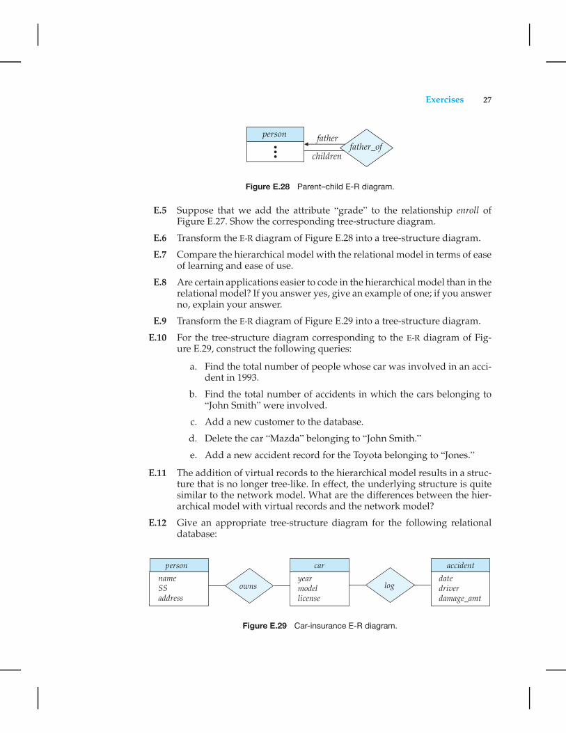
Figure E.28 Parent–child E-R diagram.
E.5 Suppose that we add the attribute “grade” to the relationship enroll ofFigure E.27. Show the corresponding tree-structure diagram.
E.6 Transform the E-R diagram of Figure E.28 into a tree-structure diagram.
E.7 Compare the hierarchical model with the relational model in terms of easeof learning and ease of use.
E.8 Are certain applications easier to code in the hierarchical model than in therelational model? If you answer yes, give an example of one; if you answerno, explain your answer.
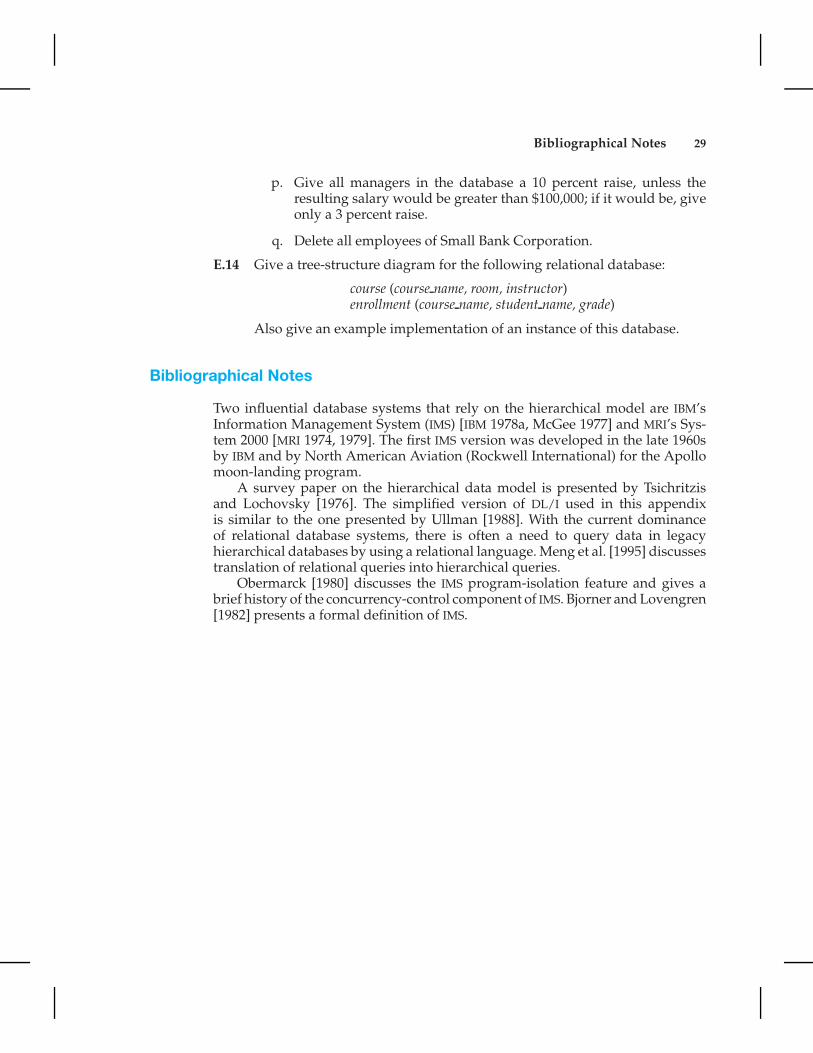
E.9 Transform the E-R diagram of Figure E.29 into a tree-structure diagram.
E.10 For the tree-structure diagram corresponding to the E-R diagram of Fig-ure E.29, construct the following queries:
a. Find the total number of people whose car was involved in an acci-dent in 1993.
b. Find the total number of accidents in which the cars belonging to“John Smith” were involved.
c. Add a new customer to the database.
d. Delete the car “Mazda” belonging to “John Smith.”
e. Add a new accident record for the Toyota belonging to “Jones.”
E.11 The addition of virtual records to the hierarchical model results in a struc-ture that is no longer tree-like. In effect, the underlying structure is quitesimilar to the network model. What are the differences between the hier-archical model with virtual records and the network model?
E.12 Give an appropriate tree-structure diagram for the following relationaldatabase:
Figure E.29 Car-insurance E-R diagram.

28 Appendix E Hierarchical Model
employee (person name, street, city)works (person name, company name, salary)company (company name, city)manages (person name, manager name)
E.13 Consider the database schema corresponding to the tree-structure diagramthat you obtained as a solution to Exercise E.12. For each of the followingqueries, construct the appropriate program:
a. Find the names of all employees who work for First Bank Corpora-tion.
b. Find the names and cities of residence of all employees who workfor First Bank Corporation.
c. Find the names, streets, and cities of residence of all employees whowork for First Bank Corporation and earn more than $10,000.
d. Find all employees who live in the city where the company for whichthey work is located.
e. Find all employees who live in the same city and on the same streetas their managers.
f. Find all employees in the database who do not work for First BankCorporation.
g. Find all employees in the database who earn more than every em-ployee of Small Bank Corporation.
h. Assume that the companies can be located in several cities. Find allcompanies located in every city in which Small Bank Corporation islocated.
i. Find all employees who earn more than the average salary of em-ployees who work in their company.
j. Find the company that employs the most people.
k. Find the company that has the smallest payroll.
l. Find those companies that pay higher salaries, on average, than theaverage salary at First Bank Corporation.
m. Modify the database such that Jones now lives in Newtown.
n. Give all employees of First Bank Corporation a 10 percent raise.
o. Give all managers in the database a 10 percent raise.
Bibliographical Notes 29
p. Give all managers in the database a 10 percent raise, unless theresulting salary would be greater than $100,000; if it would be, giveonly a 3 percent raise.
q. Delete all employees of Small Bank Corporation.
E.14 Give a tree-structure diagram for the following relational database:
course (course name, room, instructor)enrollment (course name, student name, grade)
Also give an example implementation of an instance of this database.
Bibliographical Notes
Two influential database systems that rely on the hierarchical model are IBM’sInformation Management System (IMS) [IBM 1978a, McGee 1977] and MRI’s Sys-tem 2000 [MRI 1974, 1979]. The first IMS version was developed in the late 1960sby IBM and by North American Aviation (Rockwell International) for the Apollomoon-landing program.
A survey paper on the hierarchical data model is presented by Tsichritzisand Lochovsky [1976]. The simplified version of DL/I used in this appendixis similar to the one presented by Ullman [1988]. With the current dominanceof relational database systems, there is often a need to query data in legacyhierarchical databases by using a relational language. Meng et al. [1995] discussestranslation of relational queries into hierarchical queries.
Obermarck [1980] discusses the IMS program-isolation feature and gives abrief history of the concurrency-control component of IMS. Bjorner and Lovengren[1982] presents a formal definition of IMS.
