hierarchical structures for a robustness-oriented capacity
TRANSCRIPT
Hierarchical structures for a robustness-oriented capacity design
September 18, 2018
E. Masoero1, F. K. Wittel2, H. J. Herrmann3, B. M. Chiaia4.
Abstract
In this paper, we study the response of 2D framed structures made of rectangular cells, to the suddenremoval of columns. We employ a simulation algorithm based on the Discrete Element Method, wherethe structural elements are represented by elasto-plastic Euler Bernoulli beams with elongation-rotationfailure threshold. The effect of structural cell slenderness and of topological hierarchy on the dynamicresidual strength after damage R1 is investigated. Topologically hierarchical frames have a primarystructure made of few massive elements, while homogeneous frames are made of many thin elements. Wealso show how R1 depends on the activated collapse mechanisms, which are determined by the mechanicalhierarchy between beams and columns, i.e. by their relative strength and stiffness. Finally, principles ofrobustness-oriented capacity design which seem to be in contrast to the conventional anti-seismic capacitydesign are addressed.
Keywords: frames, progressive collapse, robustness, hierarchy
Introduction
Since many decades, design codes ensure a very low probability that a building collapses under ordinaryloads, like self weight, dead and live service load, or snow. Nevertheless buildings still do collapse, from timeto time. An extremely small fraction of collapses originates from unlikely combinations of intense ordinaryload with very poor strength of the building. The majority of structural collapses are due to accidental eventsthat are not considered in standard design. Examples of such events are: gross design or construction errors,irresponsible disregard of rules or design prescriptions, and several rare load scenarios like e.g. earthquakes,fire, floods, settlements, impacts, or explosions [Alexander, 2004]. Accidental events have low probabilityof occurrence, but high potential negative consequences. Since risk is a combination of probability andconsequences, the risk related to accidental events is generally significant [BS Eurocode 1, 2004].
In 1968 a gas explosion provoked the partial collapse of the Ronan Point building in London. This eventhighlighted for the first time the urgency for robust structures, enduring safety in extraordinary scenarios[Pearson and Delatte, 2005]. Since then, interes was driven by striking catastrophic collapses [Val and Val,2006], until in 2001 the tragic collapse of the World Trade Center renewed the attention to the topic (seee.g. [Bazant and Zhou, 2002] and [Cherepanov and Esparragoza, 2007]). The last decades, several designrules aimed at improving structural robustness have been developed (see e.g. [Masoero, 2010]).
Accidental events can be classified into identified and unidentified [BS Eurocode 1, 2004; DoD, 2005].Identified events are statistically characterizable in terms of intensity and frequency of occurrence. Examples
1Dr., Politecnico di Torino, Department of Structural and Geotechnical Engineering, Corso Duca degli Abruzzi 24, 10129Torino, Italy. Massachusetts Institute of Technology, Department of Civil and Environmental Engineering, 77 MassachusettsAvenue, 02139, Cambridge, MA, U.S.A. Email address: [email protected]
2Dr., ETH Zurich, Institute for Building Materials, Schafmattstrasse 6, 8093 Zurich, Switzerland. Email address: [email protected]
3Prof., ETH Zurich, Institute for Building Materials, Schafmattstrasse 6, 8093 Zurich, Switzerland. Email address:[email protected]
4Prof., Politecnico di Torino, Department of Structural and Geotechnical Engineering, Corso Duca degli Abruzzi 24, 10129Torino, Italy. Email address: [email protected]
1
arX
iv:1
509.
0195
0v1
[co
nd-m
at.s
oft]
7 S
ep 2
015

are earthquakes, fire not fueled by external sources, gas explosions, and unintentional impacts by ordinaryvehicles, airplanes, trains, or boats. Specific design rules and even entire codes are devoted to specificidentified accidental events. Unidentified events comprise a wide variety of incidents whose intensity andfrequency of occurrence can not be described statistically, e.g. terrorist attacks or gross errors.
The risk related to unidentified accidental events can be mitigated both by structural and nonstructuralmeasures [Gulvanessian and Vrouwenvelder, 2006]. Nonstructural measures such as barriers and monitoringcan reduce the probability that an accidental event affects the structural integrity, others like a wise dis-tribution of plants and facilities can minimize the negative consequences of eventual collapses. Otherwise,structural measures can improve local resistance of structural elements to direct damage, e.g. the design ofkey elements for intense local load [BS Eurocode 1, 2004], or the application of the Enhanced Local Resis-tance method [DoD, 2005]. Structural measures can also provide progressive collapse resistance, i.e. preventspreading of local direct damage inside the structure to an extent that is disproportioned with respect tothe initial event. Usual strategies to improve progressive collapse resistance are compartmentalization ofstructures [Starossek, 2006] and delocalization of stress after local damage. Stress delocalization can beobtained exploiting redundancy, plastic stress redistributions (Masoero, Wittel et al., 2010), ties [Alexander,2004], and moment resisting connections [Hamburger and Whittaker, 2004; Vlassis et al., 2008].
Nowadays several design codes employ the conventinal Alternate Load Path Method (ALPM) to evaluateprogressive collapse resistance, e.g. [GSA, 2003] and [DoD, 2005]. The method consists in removing one keyelement, generally a column or a wall, and measuring the extent of subsequent collapse. If the final collapseis unacceptably wide, some of the previously listed measures have to be employed. Hence structures are firstdesigned and subsequently tested to be robust - they are not conceived a priori. This course of action excludesoptimizations of the basic structural topology and geometry, that actually play a key role in the response tolocal damage, considering as an example the very different behavior of redundant and statically determinedstructures. Anti-seismic design [BS Eurocode 8, 2004] already contains some prescriptions that shouldbe considered before starting a new design, e.g. geometric regularity on the horizontal and on the verticalplanes. Furthermore, anti-seismic capacity design requires a hierarchy of the structural elements ensuring thatearthquakes can only provoke ductile collapse of the horizontal beams, while failure of columns and brittleruptures due to shear are inhibited. Differently, for what concerns progressive collapse resistance, optimaloverall geometric features are not known, except for the concepts of redundancy and compartmentalization.Furthermore, the idea of hierarchically maximizing progressive collapse resistance is completely absent.
In this paper, we make a first step to cover this deficiency, showing that progressive collapse resistancecan be improved by hierarchy in the overall geometry (topological hierarchy) and in the relative strength andstiffness of horizontal and vertical structural elements (mechanical hierarchy). Our approach incorporatesthe simulation of progressive collapse of regular 2D frames made of reinforced concrete (RC) subjected tothe sudden removal of structural elements, following the ALPM framework. We first describe the analyzedframe structures and briefly sketch the approach that is based on the Discrete Element Method (DEM).After the model description, we present the results of the simulations, with focus on the effect of geometryand hierarchy on the activated collapse mechanisms and, consequently, on progressive collapse resistance.
Hierarchical structures and damage
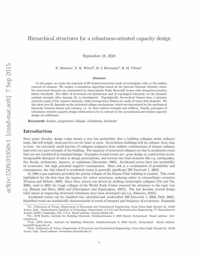
We consider two representative sets of regular 2D framed structures in Fig. 1-a. Each set consists of threeframes with identical total width Ltot and different topological hierarchical level 1/n, where n2 is the numberof structural cells in a frame. The horizontal beams, excluded those of the secondary structure, carry auniform load per unit length qext. The frames are made of RC with typical mechanical parameters ofconcrete and steel, as shown in Table 1. The total height Htot of the structure is kept constant, and twodifferent height-bay aspect ratios λ = H/L of the structural cells are considered (λ = 0.75 and λ = 1.33).
There exist several ways of introducing hierarchy into the topology of framed structures; here we call astructure “hierarchical” if it has a primary structure, made of few massive structural elements, that supportsa secondary one. The latter defines the living space and has negligible stiffness and strength compared to theprimary structure. The frames with n = 2 and n = 5 can be seen as reorganizations of those with n = 11.In detail, each column of the frames with n = 5 corresponds to two columns of the frames with n = 11, andthe same is valid for the beams, disregarding the first floor beam of the frames with n = 11, which is simply
2
(a) (b)
L
Secondary structure
H
H
LLtot = 44m
Hto
t = 3
3mH
tot =
33m
Ltot = 24.75m
1 2 n
n
2
1 2 nc
1 2nr,s
ns
1 2 nr,cRebars
hc
bc
hb
bb!
3/4
4/3
1/n1/51/2 1/11
Figure 1: a) Map of the studied frames. The cohesion of the elements inside the dotted damage area issuddenly removed to represent the initial accidental damage. b) Cross sections and rebars of beams (above)and columns (below).
deleted (see Fig. 1-a). Analogously, the geometry of the frames with n = 2 can be obtained starting fromthe frames with n = 5.
The cross sections of columns are square (see Fig. 1-b), with edges hc = bc proportional to H withfactor λc = 1/10. The beams have rectangular cross section whose height hb is proportional to L with factorλb = 1/10, and whose base bb is proportional to hb with aspect ratio δb = 2/3. The reinforcement is arrangedas shown in Fig. 1-b, with area As proportional to the area of the cross section by factor ρs,c = 0.0226 forthe columns (i.e. 8φ18 when n=11), and ρs,b = 0.0029 for the beams (i.e. 4φ14 when n=11).
The damage areas, (dotted in Fig. 1-a) contain the structural elements that are suddenly removed torepresent an accidental damage event, following the ALPM framework. The damage is identical for frameswith same λ, and is defined by the breakdown of one third of the columns on a horizontal line. The columnsand beams removed from frames with n = 11 correspond to the structural elements removed from frameswith n = 5 and n = 2. This kind of damage is employed to represent accidental events with a given
Parameter Symbol Units V alue
Reinforced concreteSpecific weight γRC kg/m3 2500Young modulus Ec N/m2 30·109
Compressive strength (high) fc N/m2 35·106
Compressive low (low) fc N/m2 0.35·106
Ultimate shortening εu,c - 0.0035SteelYoung’s modulus Es N/m2 200·109
Yield stress fy N/m2 440·106
Ultimate strain εu,s - 0.05
Table 1: Mechanical properties of reinforced concrete and steel.
3

amount of destructive energy or spatial extent, like explosions or impacts. In this work we do not explicitlysimulate very local damage events like gross errors, which would be better represented by the removal ofsingle elements. Nevertheless, we will generalize our results to consider also localized damage events.
DEM model
We employ the Discrete Element Method (DEM) to simulate the dynamics after a sudden damage [Poscheland Schwager, 2005; Carmona et al., 2008]. DEM is based on a Lagrangian framework, where the structureis meshed by massive elements interacting through force potentials. The equations of motion are directlyintegrated, in our case using a 5th order Gear predictor-corrector scheme, with time increments between10−6s and 10−5s (see Masoero, Wittel et al., 2010). DEM is an equivalent formulation to Finite Elements,converging to the same numerical solution of the dynamics if identical force-displacement laws are imple-mented. A detailed description of the algorithm for 3D systems can be found in (Masoero, Wittel et al.,2010); [Masoero, 2010], together with a discussion on the applicability. For this work, the code was restrictedto 2D by allowing only two displacements and one rotation in the vertical plane. In (Masoero, Vallini et al.,2010), the DEM model is tested against dynamic energy-based collapse analyses of a continuous horizontalbeam suddenly losing a support. In the appendix, we compare our DEM results to experimental observa-tions of a 2D frame undergoing quasi-static column removal [Yi et al., 2008]. To the best of our knowlede,literature still lacks on experiments of dynamic collapse of framed structures due to accidental damage.
In the following we will review only the essentials of our model, focusing on the details tha are relevantfor the application to 2D frames. We assume simplified force-displacement laws for the beam element andfor the Hertzian contacts. Predicting collapse of real structures would require more specialized interaction ascompared to here, for example using the fiber approach for the cross sections. By contrast, we are interestedin fundamental mechanisms of damage propagation within complex structural systems. In this researchperspective, and according to a basic principle of Statistical Mechanics, minimizing the complexity of localinteractions improves the interpretation of the systemic response. Despite the strong assumptions, in theAppendix we show that our model can match reasonably well with with experimental observations.
Structural representation
In a first step, the structure needs to be assembled by discrete elements and beams. Fig. 2-a shows the fourtypes of Spherical Discrete Elements (SDE) that we employed. Columns and beams are made of 9 SDEs,respectively with diameter Dc = 0.8hc and Db = 0.8hb, slightly smaller than the distance between them toprevent contact form occurring before local rupture. Constrained SDEs and connection SDEs have samediameter Dc as column SDEs. The constrained SDEs are clamped to a plane that represents the ground bymeans of the Hertzian contact model, discussed further in this section.
Beam SDEs
Connection SDEs
Column SDEs
Constraint SDEs
Ground plane
(a) (b)
!0
!1
N0
B0
Le
Le + "Le
1
T1
T0
B1
0
N1
Figure 2: a) Typical DEM mesh of a 2D frame. The centers of the spheres are connected by b) Euler-Bernoullibeam elements, shown in undeformed (above) and deformed state (below).
4
Euler-Bernoulli beam elements
Pairs of SDEs are connected by Euler-Bernoulli beam elements - (EBE) that, when deformed, transmitforces and moments to their edge nodes, locally labeled 0 and 1 (see Fig. 2-b). The mass M of an SDE isdefined on the basis of the EBEs connected to it. Namely M =
∑e
1/2 γRCAeLe, where e labels the generic
EBE connected to SDE, and Ae is the cross sectional area of the structural element corresponding to theEBE. The external load qext is introduced adding a mass qextL
e/g to the beam SDEs. qext is not treateddirectly as a force to avoid downward accelerations of the SDEs greater than gravity g during free fall.
For sufficiently small deformations, the EBEs are linear elastic and exert a force N proportional tothe elongation ε and directed along the 01 segment, a shear force T proportional to the sum of the nodalrotations 6 (ϕ0 + ϕ1), and a bending moment B proportional to the nodal effective rotations, defined as
ϕeff0 = 4ϕ0 + 2ϕ1, and ϕeff
1 = 2ϕ0 + 4ϕ1. Furthermore, we introduce damping by forces and momentsdirected opposite to N , T , and B, and proportional to the time derivative of ε with factor γL = 100Ns/m,and of ϕ0,ϕ1 with factor γB = 10Nms. Geometric nonlinearity due to large displacements is considered byreferring rotations and elongation to the 01 segment. In the small deformations regime of our simulations,N is with good approximation equal to the axial force inside the EBE, and thus perpendicular to T .
If N overcomes a yield threshold in tension Ny or under compression Ncy, the ideally plastic regime isentered and plastic axial strain εpl is applied to maintain N = Ny or N = Ncy. Neglecting the contributionsof concrete in tension and of steel in compression, we set the yield thresholds in terms of N and ε to:
Ny = Asfy → εy =Ny
AeEc=ρsfyEc
, and (1)
Ncy = (Ae −As) fc → εcy =Ncy
(Ae −As)Ec≈ fcEc
. (2)
Ideally plastic regime in bending is entered when |B| ≥ By. We obtain the bending yield threshold By
and the corresponding yielding effective rotation ϕeffy , neglecting the strength contribution of concrete and
assuming a lever arm between upper and lower reinforcement equal to the height h of the cross section:
By = tsρsAefyh+ ∆By and ϕeff
y =By
EcIeLe . (3)
Ie is the cross sectional moment of inertia of the EBE, and ts is the fraction of reinforcement in tension (3/8for columns and 1/2 for beams, as in Fig. 1-b). ∆By considers the beneficial compression effect compressionin the EBE. We set ∆By assuming bending carried by the reinforcement alone, and that the strain εs (∆By)in the reinforcement put under tension by ∆By equals the compressive strain εs (N) due to N < 0, namely:
εs (N) = εs (∆By) → − N
AeEc=
∆By
tsρsAehEs. (4)
In this way, eventual tension N > 0 inside the EBE produces negative ∆By, and thus reduces By. Whenyielding in bending occurs, plastic rotations are added at the edge nodes of the EBE. If only |Bi|, with
i = 0, 1, is greater than By, then only ϕpli is applied to restore |Bi| = By. Differently, if both |B0| and |B1|
are greater than By, both ϕpl0 and ϕpl
1 are applied to restore |B0| = |B1| = By. For the sake of simplicity,we assume yielding in bending uncoupled from yielding in axial direction. Furthermore, we neglect yieldingdue to shear because small plastic deformations are generally associated with shear.
We consider an EBE failed when excessive εpl and ϕpl are cumulated. For this purpose, the coupledbreaking criterion:
εpl
(εth − εy)+ max
i
∣∣∣ϕpl
i
∣∣∣ϕth
≥ 1 if εpl > 0 and (5)
− εpl
|εcth − εcy|+ max
i
∣∣∣ϕpl
i
∣∣∣ϕth
≥ 1 if εpl < 0 , (6)
5
is employed. εth, εcth, and ϕth are the maximum allowed plastic elongation, shortening, and rotation inuncoupled conditions. We consider high plastic capacity of the structural elements setting εth = 2εu,s,εcth = 2εu,c, and ϕth = 0.2rad (see Table 1). Failed EBEs are instantly removed from the system. Weneglect ruptures due to shear assuming that, in agreement with a basic principle of capacity design, asufficient amount of bracings ensures the necessary shear strength.
Inter-sphere contact
The Hertzian contact model is employed for the SDEs to consider collisions between structural elements.The model consist of repulsive forces between partially overlapping SDEs, damped by additional forcesproportional and opposite to the overlapping velocity. We also set tangential forces that simulate static anddynamic friction, as well as damping moments opposed to the relative rolling velocity. A similar Hertziancontact model is also employed for SDEs colliding with the ground plane. In the following simulationswe employ contact parameters that can be found in [Masoero, 2010]. We do not transcribe them becauseimpacts do not affect significantly the collapse mechanisms sudied here. Nevertheless, in general simulationalgorithms for progressive collapse should consider impacts, because initial damage located at upper storiesgenerates falling debris, and because impacts can drive the transition from partial to total collapse (see(Masoero, Wittel et al., 2010) and [Bazant and Zhou, 2002]). In granular dynamics, the contact parametersare generally set referring to the material of the grains [Poschel and Schwager, 2005]. In our model theSDEs represent large heterogeneous portions of structural elements, for which there are not conventionallydefined contact parameters so far. We emply parameters yielding a qualitatively realistic dynamics (e.g. theelements do not rebound or pass through each other), and chosen from sets of possible one that were definedthrough preliminary studies. Such studies also indicated that the collapse loads of a beam due to debrisimpact varies of less than 15% upon orders of magnitude change in the contact parameters.
Simulating progressive collapse
The simulations are organized into two steps: first the structure is equilibrated under the effect of qext andgravity, then the EBEs inside the damage area are suddenly removed, and the subsequent dynamic responseis simulated. Our aim is to quantify three collapse loads:
• qIu: maximum static load that the intact structure can carry;
• qc: minimum critical load that causes dynamic collapse after damage. Applied statically to the intactstructure first, it is then kept constant during the post-damage dynamic response.
• qp,t: minimum load corresponding to total collapse after damage. By definition, qc ≤ qp,t ≤ qIu.
In our DEM model we do not have a straightforward unique measure of load, because the mass of the SDEsdepends on the external load qext and on the self weight of the structural elements. The mass of the beamSDEs effectively acts as a distributed horizontal load. On the other hand, the columns at each story transmitvertical concentrated forces either to other columns at a lower story, or to the horizontal transfer beam overthe damage area. Therefore we introduce a load measure that we call equivalent load qeq, applied to themassless structure and analytically related to the geometry, the mass, and the activated collapse mechanismof the frames in the simulations. Namely, qeq is defined to produce the same static effect as the variousmasses and concentrated forces of the simulation frames, at the critical points where collapse is triggered.The derivation of the analytical expressions used in this work is shown in [Masoero, 2010].
For each analyzed structure, we first apply the entire structural mass. In a subsequent step, the externalload qext is increased until the intact structure collapses in static conditions. The collapse mechanismindicates what equivalent load expression should be used to compute qIu. Then we slightly decrease qext,equilibrate, introduce the damage, and calculate whether dynamic progressive collapse is triggered and towhat an extent. Performing several simulations with progressively smaller qext, the final extent of collapsechanges from total to partial, and we employ again an adequate equivalent load to compute qp,t. If thestructure collapses even when qext is reduced to zero, we start reducing the specific weight of the structuralelements, i.e. the structural mass. When dynamic collapse does not occur anymore, an adequate equivalent
6

load provides qc. Once we obtain the collapse loads, we estimate the progressive collapse resistance referringto the residual strength fraction R1 = qc/q
Iu. Actually, progressive collapse resistance is more directly related
to qc, but the advantage of R1 is that it can not be improved by simply strengthening the structural elements,which would increase both qc and qIu. Robustness-oriented structural optimization is required to increaseR1, which therefore is a good indicator to compare different structural solutions.
Bending collapse
In our model, the bending yield threshold By does not depend on the strength of concrete fc. Therefore,setting the high value fc = 35N/mm2, the mainly compressed columns get much stronger than the horizontalbeams, that fail in bending (see Figs. 3,4). The resulting collapse mechanisms resemble triple-hinge and fourhinges mechanisms, reflecting the large plastic capacity of the structural elements.
1/5 1/21/111/n
3/4
4/3
!
t = 0.5s t = 0.6s t = 0.8s
t = 0.5s t = 0.5s t = 0.8s
Figure 3: Static bending collapse mechanism before damage. Time t = 0s corresponds to the first breakingof an EBE.
1/5 1/21/111/n
3/4
4/3
!
t = 2.0s t = 2.0s t = 1.6s
t = 2.1s t = 2.0s t = 2.4s
Figure 4: Dynamic bending collapse mechanism after damage. Time t = 0s corresponds to the applicationof the initial damage.
If the initial damage triggers a bending mechanism, frames with n = 2 undergo total collapse, whileframes with lower hierarchical level 1/n initially suffer only a local collapse (see Fig. 5). The local collapse
7

can nevertheless evolve to total collapse, if high applied load and plastic capacity cause the falling centralpart of the structure to dynamically drag down the lateral portions (Masoero, Wittel et al., 2010).
1.4 4.30.5t[s]
13
26
qeq[kN/m]
2.5 4.10.4t[s]
Figure 5: Snapshots of partial (qeq=13kN/m) and total (qeq=26kN/m) bending collapse after damage of aframe with very strong columns, n=11, and λ = 1.33. Time t = 0s corresponds to the application of theinitial damage.
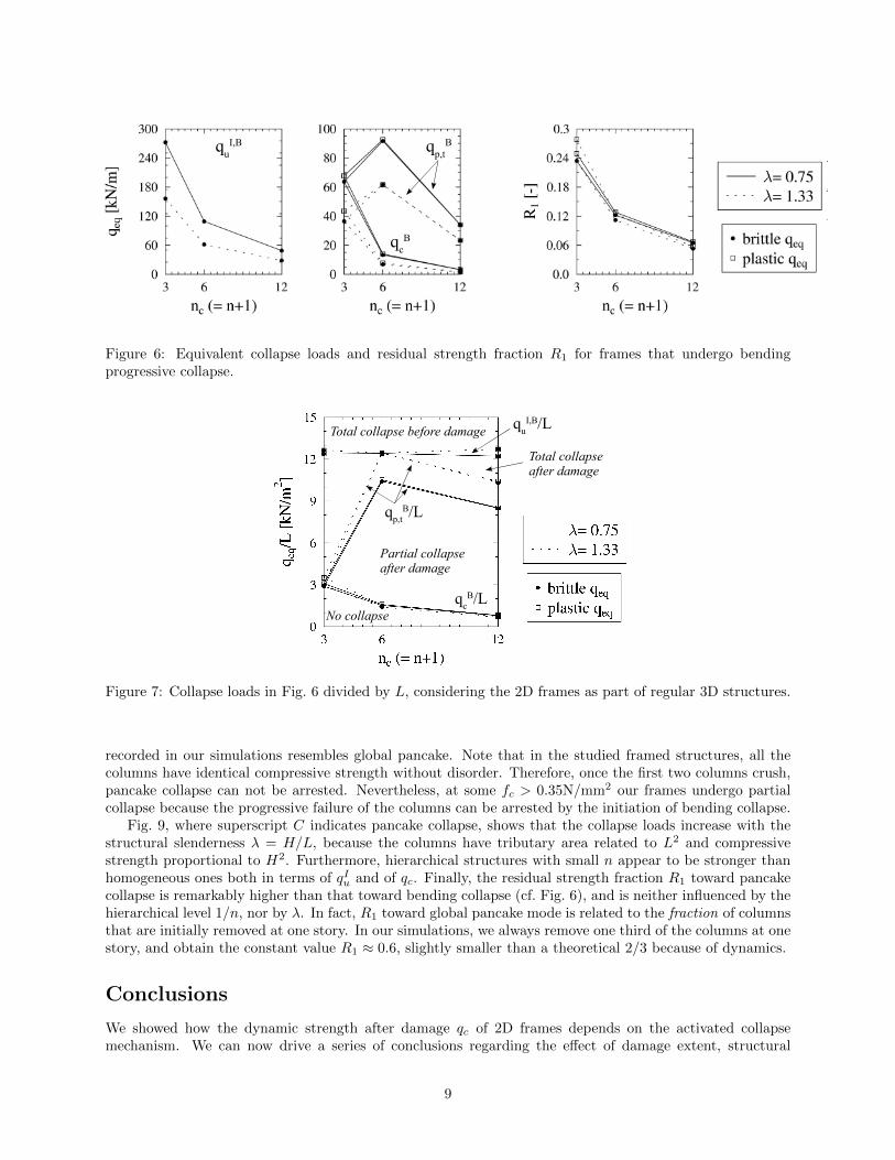
The collapse loads, expressed in terms of equivalent loads qeq, are summarized in Fig. 6 as a functionof the hierarchical level 1/n, for different slenderness of the structural cells λ. In Fig. 6, superscript Bindicates bending collapse mechanism. We employ equivalent loads referring to perfectly brittle or perfectlyplastic bending failure (see the Appendix). The collapse loads decrease with λ, i.e. a slender structure seemsweaker, and increase with 1/n, i.e. hierarchical frames are stronger. The residual strength fraction R1 doesnot depend on λ, while hierarchical structures with low n are more robust than homogeneous ones (seeFig. 6). In fact, the concentration of bending moment at the connection between a beam hanging above thedamage area and the first intact column depends on the number of removed columns. In the simulations,we remove a constant fraction of one third of the columns on a horizontal line (see Fig. 1). Thereforehomogeneous structures lose more columns and are less robust toward the bending collapse mechanisms. Onthe other hand, since the number of removed columns is decisive, we expect that the hierarchical level doesnot influence R1 toward bending collapse in case of single column removal. Finally we consider the 2D frameas part of a regular 3D structure and divide the collapse loads in Fig. 6 by L, i.e.by the tributary length ofthe beams in the direction perpendicular to the frame. In this way, collapse loads per unit area are obtainedin Fig. 7, showing that: λ does not influence qc/L and qIu/L; structures with slender cells are less likely tocollapse entirely; qIu/L is independent from the hierarchical level; qc/L is proportional to 1/n.
Pancake collapse
Progressive compressive failure of the columns, also called pancake collapse, occurs when we set the com-pressive strength of concrete to a small value fc = 0.35N/mm2 (see Fig. 8). This choice is unphysical butallows us to separate the effect of strength reduction from that of stiffness reduction in the columns. Morerealistic scenarios would involve columns with small cross section and highly reinforced, tall beams.
The columns immediately next to the damage area are the first to fail under compression, and thenprogressive collapse spreads horizontally to the outside. We employ equivalent loads qeq referring to thetwo limit cases of local and of global pancake collapse. Local pancake collapse occurs when the bendingstiffness of the beams is very low and when the compressive failure of the columns is very brittle. In thiscase, the overload after damage is entirely directed to the intact columns that are closer to the damage area,and collapse propagates by nearest neighbor interactions. On the other hand, high stiffness of the beamsand large plastic capacity of the columns induce democratic redistribution of overload between the columns.Consequently, the columns crush simultaneously triggering global pancake collapse. The collapse dynamics
8
quI,B qp,t
B
qcB
Figure 6: Equivalent collapse loads and residual strength fraction R1 for frames that undergo bendingprogressive collapse.
No collapse
Total collapse before damage
Partial collapse after damage
Total collapse after damage
qcB/L
qp,tB/L
quI,B/L
Figure 7: Collapse loads in Fig. 6 divided by L, considering the 2D frames as part of regular 3D structures.
recorded in our simulations resembles global pancake. Note that in the studied framed structures, all thecolumns have identical compressive strength without disorder. Therefore, once the first two columns crush,pancake collapse can not be arrested. Nevertheless, at some fc > 0.35N/mm2 our frames undergo partialcollapse because the progressive failure of the columns can be arrested by the initiation of bending collapse.
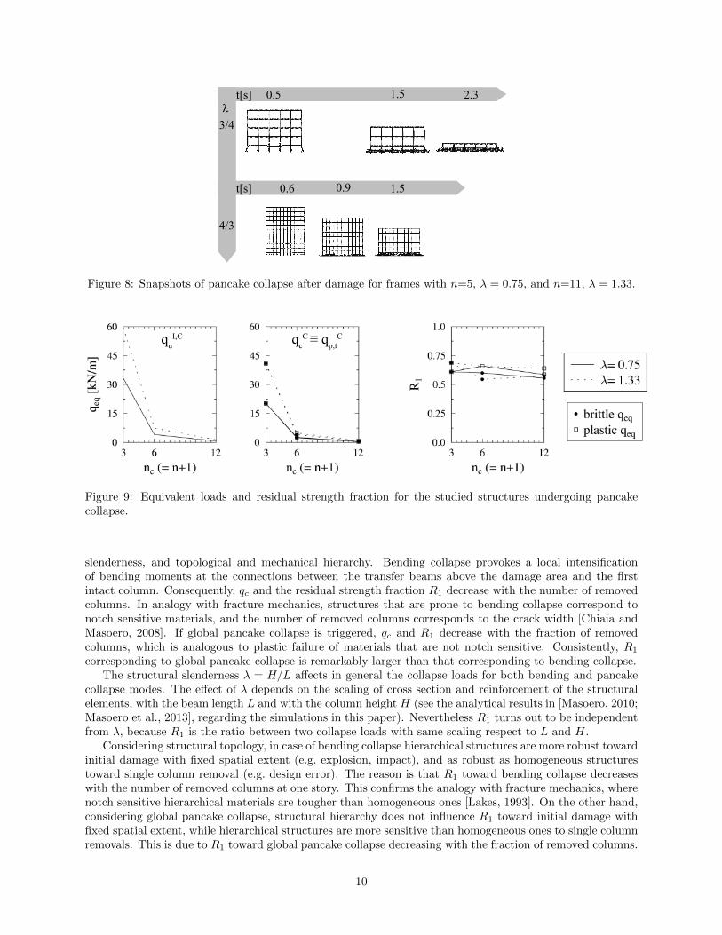
Fig. 9, where superscript C indicates pancake collapse, shows that the collapse loads increase with thestructural slenderness λ = H/L, because the columns have tributary area related to L2 and compressivestrength proportional to H2. Furthermore, hierarchical structures with small n appear to be stronger thanhomogeneous ones both in terms of qIu and of qc. Finally, the residual strength fraction R1 toward pancakecollapse is remarkably higher than that toward bending collapse (cf. Fig. 6), and is neither influenced by thehierarchical level 1/n, nor by λ. In fact, R1 toward global pancake mode is related to the fraction of columnsthat are initially removed at one story. In our simulations, we always remove one third of the columns at onestory, and obtain the constant value R1 ≈ 0.6, slightly smaller than a theoretical 2/3 because of dynamics.
Conclusions
We showed how the dynamic strength after damage qc of 2D frames depends on the activated collapsemechanism. We can now drive a series of conclusions regarding the effect of damage extent, structural
9
3/4
4/3
!1.5 2.30.5t[s]
0.9 1.50.6t[s]
Figure 8: Snapshots of pancake collapse after damage for frames with n=5, λ = 0.75, and n=11, λ = 1.33.
quI,C qc
C ! qp,tC
Figure 9: Equivalent loads and residual strength fraction for the studied structures undergoing pancakecollapse.
slenderness, and topological and mechanical hierarchy. Bending collapse provokes a local intensificationof bending moments at the connections between the transfer beams above the damage area and the firstintact column. Consequently, qc and the residual strength fraction R1 decrease with the number of removedcolumns. In analogy with fracture mechanics, structures that are prone to bending collapse correspond tonotch sensitive materials, and the number of removed columns corresponds to the crack width [Chiaia andMasoero, 2008]. If global pancake collapse is triggered, qc and R1 decrease with the fraction of removedcolumns, which is analogous to plastic failure of materials that are not notch sensitive. Consistently, R1
corresponding to global pancake collapse is remarkably larger than that corresponding to bending collapse.The structural slenderness λ = H/L affects in general the collapse loads for both bending and pancake
collapse modes. The effect of λ depends on the scaling of cross section and reinforcement of the structuralelements, with the beam length L and with the column height H (see the analytical results in [Masoero, 2010;Masoero et al., 2013], regarding the simulations in this paper). Nevertheless R1 turns out to be independentfrom λ, because R1 is the ratio between two collapse loads with same scaling respect to L and H.
Considering structural topology, in case of bending collapse hierarchical structures are more robust towardinitial damage with fixed spatial extent (e.g. explosion, impact), and as robust as homogeneous structurestoward single column removal (e.g. design error). The reason is that R1 toward bending collapse decreaseswith the number of removed columns at one story. This confirms the analogy with fracture mechanics, wherenotch sensitive hierarchical materials are tougher than homogeneous ones [Lakes, 1993]. On the other hand,considering global pancake collapse, structural hierarchy does not influence R1 toward initial damage withfixed spatial extent, while hierarchical structures are more sensitive than homogeneous ones to single columnremovals. This is due to R1 toward global pancake collapse decreasing with the fraction of removed columns.
10

Fig. 9 shows that damaged frames undergoing global pancake collapse can carry the R1 ≈ 60% of the staticultimate load of the intact structure qIu. Since well designed structures can carry a qIu remarkably greaterthan the environmental load expected when an accidental event occurs, R1 related to global pancake collapsecan ensure structural robustness for most of the practical cases [Masoero, 2010]. On the other hand, R1
related to bending collapse is generally much smaller, making structures vulnerable to accidental damage.In this work we considered idealized structures, with simplified geometry and mechanical behavior of the
elements. Reducing local complexity enables a better interpretation of the coral system response to damage.This study provides a basis of knowledge preceding the incorporation of more details and degrees of freedom,to investigate further aspects of progressive collapse. Shear failures can cause brittle ruptures and reducethe collapse resistance of large structural elements. Different locations of the initial damage may activatedifferent collapse mechanisms. For example, damaging the upper stories would cause debris impacts, whileremoving external columns reduces qc without producing significant lateral toppling [Calvi, 2010]. The DEMalgorithm was already applied to 3D structures in (Masoero, Wittel et al., 2010), showing that the bendingand pancake collapse mechanisms persist also in 3D. On the other hand, in 3D structures the horizontalfloor slabs improve the horizontal redistribution of loads and the catenary action, increasing the strengthtoward bending collapse and impacting debris (see the Appendix and, e.g. , [Vlassis et al., 2008]). It is worthnoting that horizontal ties and diaphragms increase the strength both after and before damage, causing acompensation that limits the effect on R1. Finally, future works can incorporate a detailed description ofstructural connections, which are crucial for energy dissipation, catenary effect, and compartmentalization.
Coming back to the central theme of structural hierarchy, our results already suggest that hierarchicalstructures are more robust toward accidental damage. An optimal solution would be to design: 1) a primaryframe made of few large elements, with columns weaker than the beams, and 2) a secondary structure,made of many smaller elements, which defines the living space and follows traditional design rules. Theprimary frame would provide topological hierarchy, maximizing R1 toward bending collapse and enablingnew possible compartmentalization strategies. The strong beams and weak columns of the primary framewould favor pancake collapse over bending collapse, and improve the vertical compartmentalization of high-rise buildings against falling debris. On the other hand, in real structures, the beams generally fail beforethe columns, and imposing the opposite is expensive. Nevertheless, designing a strong-beam weak-columnbehavior only for the primary frame can significantly limit the extra cost. Hierarchical structures can bea novel and somehow counterintuitive feature of robustness-oriented capacity design. Planning structuralhierarchy requires understanding the complex system response to local damage, and should drive the designprocess since the very beginning. By contrast, traditional design is focused on local resistance againstordinary actions, and considers robustness toward accidents only at the end. This generally leads to non-hierarchical structures with strong columns and poorly understood system behavior. In addition, anti-seismiccapacity design requires plastic failure of the beams to precede columns rupture (see e.g. [Byfield, 2004]).Overcoming these contradictions is a challenge toward optimizing structures against exceptional events.
References
S. Alexander. New approach to disproportionate collapse. Struct. Eng., 82(23/24):14–18, 2004.
Z.P. Bazant and Y. Zhou. Why did the World Trade Center collapse? - Simple analysis. J. Eng. Mech.-ASCE,128(1):2–6, 2002.
BS Eurocode 1. Actions on structures - part 1-7: General actions - accidental actions. Technical Report EN1991-1-7, BSI, 2004.
BS Eurocode 8. Design of structures for earthquake resistance. Technical report, BSI, 2004.
M.P. Byfield. Design of steel framed buildings at risk from terrorist attack. Struct. Eng., 82(22):31–38, 2004.
A. Calvi. Il crollo delle torri gemelle: analisi dell’evento e insegnamenti strutturali. Master’s thesis, Politec-nico di Torino, 2010. (In Italian).
H.A. Carmona, F.K. Wittel, F. Kun, and H.J. Herrmann. Fragmentation processes in impact of spheres.Phys. Rev. E, 77(5):243–253, 2008.
11
G.P. Cherepanov and I.E. Esparragoza. Progressive collapse of towers: the resistance effect. Int. J. Fract.,143:203–206, 2007.
B.M. Chiaia and E. Masoero. Analogies between progressive collapse of structures and fracture of materials.Int. J. Fract., 154(1-2):177–193, 2008.
DoD. Unified Facilities Criteria (UFC): Design of Buildings to Resist Progressive Collapse. Technical report,Department of Defence, 2005.
GSA. General Services Administration. Progressive Collapse Analysis and Design Guidelines for New FederalOffice Buildings and Major Modernization Projects. Technical report, GSA, 2003.
H. Gulvanessian and T. Vrouwenvelder. Robustness and the eurocodes. Struct. Eng. Int., 2:161–171, 2006.
R. Hamburger and A. Whittaker. Design of steel structures for blast-related progressive collapse resistance.Modern Steel Constr., March:45–51, 2004.
R. Lakes. Materials with structural hierarchy. Nature, 361:511–515, 1993.
E. Masoero. Progressive collapse and robustness of framed structures. PhD thesis, Politecnico di Torino,Italy, 2010.
E. Masoero, P. Daro, and B.M. Chiaia. Progressive collapse of 2d framed structures: an analytical model.Engn. Struct., 54:94–102, 2013.
C. Pearson and N. Delatte. Ronan point apartment tower collapse and its effect on building codes. J. Perf.Constr. Fac. -ASCE, 19(2):172–177, 2005.
T. Poschel and T. Schwager. Computational Granular Dynamics. Springer-Verlag GmbH, Berlin, 2005.
U. Starossek. Progressive collapse of structures: nomenclature and procedures. Struct. Eng. Int., 16(2):113–117, 2006.
D.V. Val and E.G. Val. Robustness of framed structures. Struct. Eng. Int., 16(2):108–112, 2006.
A.G. Vlassis, B.A Izzuddin, A.Y. Elghazouli, and D.A Nethercot. Progressive collapse of multi-storeybuildings due to sudden column loss-Part II: application. Eng. Struct., 30(5):1424–1438, 2008.
W.-J. Yi, Q.-F. He, Y. Xiao, and S.K. Kunnath. Experimental study on progressive collapse-resistantbehavior of reinforced concrete frame structures. ACI Structural Journal, 105(4):433–439, 2008.
12

Appendix: experimental benchmark
In this appendix, we compare the numerical predictions of our DEM model with the experimental observa-tions in [Yi et al., 2008]. We also briefly discuss some effects of catenary actions on collapse resistance.
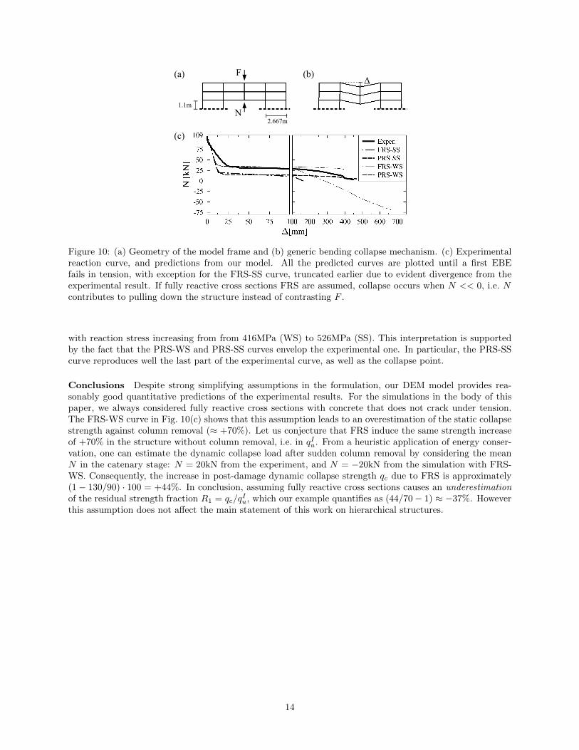
Experiments The experimental setup in [Yi et al., 2008] consists of a plane frame made of reinforcedconcrete (see Fig. 10(a)). Columns are square in section (200x200mm), beams are rectangular (200mm tall,100mm wide). Everywhere, the longitudinal reinforcement is symmetrically distributed within the crosssection (4φ12 steel bars). The strength and ultimate strain of concrete and steel are specified in [Yi et al.,2008], while the elastic moduli are not. The mid column at the first floor is replaced by jacks that providesan upward vertical force N . In the middle of the top floor, a servo-hydraulic actuator applies a constantdownward vertical force F=109kN, to represent the self weight of upper stories. Initially N = F =109kN,and then it is progressively reduced to reproduce quasi-static column loss, until a bending mechanism triggerscollapse (see Fig. 10(b)). During the experiments, the increasing values of the midspan inflection ∆ is plottedagainst N , to get the force-displacement reaction curve. The integral of the curve represents the energydissipation capacity, which relates to the dynamic strength of the structure with respect to the activatedcollapse mechanism.
Model description Our target is to capture the experimental reaction curve N −∆ through DEM simu-lations. The parametrization of our model, based on the geometry and mechanical data in [Yi et al., 2008],is straightforward. Therefore, we focus on the discrepancies between model and experimental inputs, anda few necessary additional assumptions. Regarding the overall geometry, we consider all the columns to beequally tall (1,100mm), while in the experiments the columns at the first floor were taller (1,567mm). Thisdiscrepancy should not have a significant effect on the collapse mechanism and the strength. The mechanicalbehavior of the real steel bars was strain hardening, with yielding at 416MPa, and rupture at 526MPa. Inour model, we consider two limit cases of elastic-perfectly plastic behavior of the steel bars: weak steel “WS”with yielding threshold set at 416MPa, and strong steel “SS” yielding at 526MPa. [Yi et al., 2008] providetwo measures of the ultimate tensile strain δ of the steel bars. We employ δ10 = 23%, which was measuredon a longer bar segment, because in our simulation the strain develops within relatively long Euler-BernoulliBeam Elements, EBEs. We assume Young moduli Es = 200GPa for the steel, and Ec = 30GPa for theconcrete. In order to better understand the development of catenary actions, we consider two limit cases ofcross section behavior under tension: fully reacting sections “FRS”, where the concrete always contributesto the tensile stiffness, and partially reacting sections “PRS” , where the concrete cracks and only the steelprovides axial stiffness as soon as the cross section goes in tension. Furthermore, in order to focus exclusivelyon ruptures due to tensile strain in the steel, we allow for an infinite rotation capacity of the cross sections.
Simulations and results We subject our model frames to gravity, but remain in the quasi-static regimeby adding a high viscous damping force proportional to the velocity of each Spherical Discrete Element.We repeat numerous simulations with fixed F = 109kN and N , ranging from N = 109kN to values thatare small enough to cause the quasi-static rupture of at least one EBE. We track the midspan deflection∆ (N)for comparison in Fig. 10(c).
Discussion In the experimental results, as N decreases, the system crosses several stages: (I) linear elastic∆ / 5mm, (II) elasto-plastic ∆ < 22mm, (III) plastic hinges ∆ < 140mm, (IV) catenary action ∆ < 450mm,and (V) collapse. The transition from elastic to elasto-plastic is not evident from the curve, as well as thatfrom plastic hinge to catenary action. By contrast, plastic hinges formation is clearly marked by a suddenchange of slope at ∆ ≈ 40mm. Our simulations do not capture the initial elasto-plastic stage because we donot model the non-linear elasto-plastic behavior of concrete. This leads to an overestimation of the stiffnessdN/d∆ before the formation of the plastic hinges. Nevertheless, the additional strain energy produced bythis approximation is negligible when compared to the energy dissipated in the subsequent stages, ie. theoverestimation of the initial stiffness is irrelevant for the actual dynamic collapse. Assuming weak steel WS,yielding at 416MPa, provides a good agreement with the experiment in terms of transition point to the plastichinges stage. Considering fractured concrete under tension yields the PRS-WS curve, which underestimatesthe structural strength at large ∆. The reason for this divergence can be that the steel hardens under strain,
13
(a)
N1.1m
F (b)
(c)2.667m
!
Figure 10: (a) Geometry of the model frame and (b) generic bending collapse mechanism. (c) Experimentalreaction curve, and predictions from our model. All the predicted curves are plotted until a first EBEfails in tension, with exception for the FRS-SS curve, truncated earlier due to evident divergence from theexperimental result. If fully reactive cross sections FRS are assumed, collapse occurs when N << 0, i.e. Ncontributes to pulling down the structure instead of contrasting F .
with reaction stress increasing from from 416MPa (WS) to 526MPa (SS). This interpretation is supportedby the fact that the PRS-WS and PRS-SS curves envelop the experimental one. In particular, the PRS-SScurve reproduces well the last part of the experimental curve, as well as the collapse point.
Conclusions Despite strong simplifying assumptions in the formulation, our DEM model provides rea-sonably good quantitative predictions of the experimental results. For the simulations in the body of thispaper, we always considered fully reactive cross sections with concrete that does not crack under tension.The FRS-WS curve in Fig. 10(c) shows that this assumption leads to an overestimation of the static collapsestrength against column removal (≈ +70%). Let us conjecture that FRS induce the same strength increaseof +70% in the structure without column removal, i.e. in qIu. From a heuristic application of energy conser-vation, one can estimate the dynamic collapse load after sudden column removal by considering the meanN in the catenary stage: N = 20kN from the experiment, and N = −20kN from the simulation with FRS-WS. Consequently, the increase in post-damage dynamic collapse strength qc due to FRS is approximately(1− 130/90) · 100 = +44%. In conclusion, assuming fully reactive cross sections causes an underestimationof the residual strength fraction R1 = qc/q
Iu, which our example quantifies as (44/70− 1) ≈ −37%. However
this assumption does not affect the main statement of this work on hierarchical structures.
14