hifi service manual - diagramasde.comdiagramas.diagramasde.com/otros/pa 6 grundig hifi.pdfpa 6-i...
TRANSCRIPT
PA 6-IGLI1651
PA 6-IIGLI1967
PA 6-IIIGLI1950
Zusätzlich erforderliche Unterlagen für den KomplettserviceAdditionally required Service Documents for the Complete Service
ServiceManual
Grundig ServiceHotline Deutschland...
TVTVSATVCR/LiveCamHiFi/AudioCar AudioTelekommunikation
Fax:Planatron (8.00-22.00 Uhr)
0180/52318-410180/52318-490180/52318-480180/52318-420180/52318-430180/52318-440180/52318-450180/52318-510180/52318-99
...Mo.-Fr. 8.00-18.00 Uhr
0180/52318-400180/52318-50
Telefon:Fax:
Technik:
Ersatzteil-Verkauf: ...Mo.-Fr. 8.00-19.00 Uhr
SicherheitSafety
Materialnr./Part No.72010 800 0000
HiFi Service Manual
Materialnummer/Part Number 72010 760 7000Änderungen vorbehalten/Subject to alteration • Printed in Germany • MÜE-BS 36 0800 • 8002/8012, 8005/8015, 8006/8016http://www.grundig.com
DISCOPEN/CLOSE
TAPEOPEN/CLOSE
3
2
1
DISC SELECT
1 2 3
U
B NR
Allgemeiner Teil / General Section PA 6
1 - 2 GRUNDIG Service
Es gelten die Vorschriften und Sicherheitshinweisegemäß dem Service Manual "Sicherheit", Material-nummer 72010 800 0000, sowie zusätzlich die even-tuell abweichenden, landesspezifischen Vorschriften!
The regulations and safety instructions shall be validas provided by the "Safety" Service Manual, partnumber 72010 800 0000, as well as the respectivenational deviations.
Table of ContentsPage
General Section ........................... 1 - 3 … 1 - 33Test equipment / aids ................................................................ 1 - 3Technical Data .......................................................................... 1 - 3Service Hints ............................................................................. 1 - 4Operations of the CD Mechanism ............................................. 1 - 5Disassembly Instructions .......................................................... 1 - 7Operating Hints ....................................................................... 1 - 26
Adjustment Procedures................ 2 - 1 … 2 - 7Tuner ......................................................................................... 2 - 1Alignment Layout Tuner ............................................................ 2 - 2Tape Deck ................................................................................. 2 - 5Alignment Layouts Tape Deck .................................................. 2 - 7
Circuit Diagrams andLayout of PCBs ........................... 3 - 1 … 3 - 36IC Block Diagrams .................................................................... 3 - 1Wiring Diagram ......................................................................... 3 - 2Circuit Diagrams
Audio Board, AUX In/Out Board, Mains Switch Board,Headphone Board, Illumination Board .................................. 3 - 5Tape Audio Board ................................................................. 3 - 9Tape Logic Board, Detector Board ...................................... 3 - 11CD Servo Board .................................................................. 3 - 13CD Logic Board ................................................................... 3 - 15Tuner ................................................................................... 3 - 17AF Amplifier Board .............................................................. 3 - 19Display Board ...................................................................... 3 - 21Key Boards, Eject Board ..................................................... 3 - 24
Layout of PCBsAudio Board ........................................................................ 3 - 25AUX In/Out Board, Mains Switch Board, Detector Board,Headphone Board, Illumination Board, Eject Board ............ 3 - 28Tuner ................................................................................... 3 - 29Tape Audio Board ............................................................... 3 - 30Tape Logic Board ................................................................ 3 - 31CD Logic Board ................................................................... 3 - 31CD Servo Board .................................................................. 3 - 33AF Amplifier Board .............................................................. 3 - 33Display Board ...................................................................... 3 - 35Key Boards .......................................................................... 3 - 35
Spare Parts Listsand Exploded Views ..................... 4 - 1 … 4 - 8Exploded View PA 6 ................................................................. 4 - 1Exploded View Tape Loading .................................................... 4 - 3Spare Parts List PA 6-I ............................................................. 4 - 3Spare Parts List Speaker PA 6-I ............................................... 4 - 5Spare Parts List PA 6-II ............................................................ 4 - 6Spare Parts List Speaker PA 6-II .............................................. 4 - 6Spare Parts List PA 6-III ........................................................... 4 - 7Spare Parts List Speaker PA 6-III ............................................. 4 - 7Spare Parts List Tape Drive TN 1800 D ................................... 4 - 8Exploded View Tape Drive TN 1800 D ..................................... 4 - 8
InhaltsverzeichnisSeite
Allgemeiner Teil .......................... 1 - 3 … 1 - 25Messgeräte / Messmittel ........................................................... 1 - 3Technische Daten ..................................................................... 1 - 3Servicehinweise ........................................................................ 1 - 4Funktionsbeschreibung CD-Laufwerk ....................................... 1 - 5Ausbauhinweise ........................................................................ 1 - 7Bedienhinweise ....................................................................... 1 - 18
Abgleichvorschriften .................... 2 - 1 … 2 - 7Tuner ......................................................................................... 2 - 1Abgleichlageplan Tuner ............................................................ 2 - 2Cassetten-Laufwerk .................................................................. 2 - 3Abgleichlagepläne Cassetten-Laufwerk .................................... 2 - 7
Schaltpläne undDruckplattenabbildungen ........... 3 - 1 … 3 - 36IC-Innenbeschaltungen ............................................................. 3 - 1Verdrahtungsplan ...................................................................... 3 - 2Schaltpläne
Audio-Platte, AUX-In/Out-Platte, Netzschalter-Platte,Kopfhörer-Platte, Beleuchtungsstreifen ................................ 3 - 5Cassetten-Audio-Platte ......................................................... 3 - 9Cassetten-Logik-Platte, Detektor-Platte .............................. 3 - 11CD-Servo-Platte .................................................................. 3 - 13CD-Logik-Platte ................................................................... 3 - 15Tuner ................................................................................... 3 - 17NF-Verstärker-Platte ........................................................... 3 - 19Display-Platte ...................................................................... 3 - 21Tasten-Platten, Eject-Platte ................................................ 3 - 24
DruckplattenabbildungenAudio-Platte ......................................................................... 3 - 25AUX-In/Out-Platte, Netzschalter-Platte, Detektor-Platte,Kopfhörer-Platte, Beleuchtungsstreifen, Eject-Platte .......... 3 - 28Tuner ................................................................................... 3 - 29Cassetten-Audio-Platte ....................................................... 3 - 30Cassetten-Logik-Platte ........................................................ 3 - 31CD-Logik-Platte ................................................................... 3 - 31CD-Servo-Platte .................................................................. 3 - 33NF-Verstärker-Platte ........................................................... 3 - 33Display-Platte ...................................................................... 3 - 35Tasten-Platten ..................................................................... 3 - 35
Ersatzteillisten undExplosionszeichnungen ............... 4 - 1 … 4 - 8Explosionszeichnung PA 6 ....................................................... 4 - 1Explosionszeichnung Cassetten-Loading ................................. 4 - 3Ersatzteilliste PA 6-I .................................................................. 4 - 3Ersatzteilliste Speaker PA 6-I ................................................... 4 - 5Ersatzteilliste PA 6-II ................................................................. 4 - 6Ersatzteilliste Speaker PA 6-II .................................................. 4 - 6Ersatzteilliste PA 6-III ................................................................ 4 - 7Ersatzteilliste Speaker PA 6-III ................................................. 4 - 7Ersatzteilliste Cassetten-Laufwerk TN 1800 D ......................... 4 - 8Explosionszeichnung Cassetten-Laufwerk TN 1800 D ............. 4 - 8
PA 6 Allgemeiner Teil / General Section
GRUNDIG Service 1 - 3
Technische Daten
VerstärkerSinusleistung ........................................................................... 200WMusikleistung .......................................................................... 360WEingangsempfindlichkeit / Impedanz ........................ 180mV / 47kΩSignal-Rausch-Abstand ....................................................... >100dBKlirrfaktor (-1dB, 8Ω, 1kHz) .................................................... 0,01%Leistungsbandbreite ................................................. 10Hz … 80kHzFrequenzbereich (AUX IN) ....................................... 5Hz … 100kHz
TunerEmpfindlichkeit
Mono (S/N=26dB) .............................................................. 1,5µV Stereo (S/N=46dB) .............................................................. 31µV
FM (25kHz Schrittweite) ......................................... 87,5 … 108MHzStereo Übersprechen (1kHz) ................................................... 40dBFrequenzbereich (-3dB) ........................................... 10Hz … 15kHz
CD-PlayerFrequenzgang (±0,5dB) ........................................... 20Hz … 20kHzKlirrfaktor (IEC gew.) ............................................................ <0,01%Stereo Übersprechen ............................................................... >85BIntermodulation ...................................................................... <0,1%Dynamikbereich ..................................................................... >90dBSignal-Rausch-Abstand (gew.) ............................................ >104dBPhasenlinearität ....................................................................... +0,5°
CassettendeckFrequenzbereich ...................................................... 40Hz … 16kHzSignal-Rausch-Abstand
mit Dolby B ........................................................................... 64dBohne Dolby ........................................................................... 56dB
Gleichlauf ............................................................................... 0,13%Stereo Übersprechen (1kHz) ................................................... 40dB
StromversorgungNetzspannung ................................................................. 230-240V~Netzfrequenz ..................................................................... 50 / 60HzLeistungsaufnahme ............................................................... <400WLeistungsaufnahme bei Standby ............................................... <2W
Technical Data
AmplifierNominal power ........................................................................ 200WMusic power ............................................................................ 360WInput sensitivity / impedance ..................................... 180mV / 47kΩSignal-to-noise ratio ............................................................. >100dBDistortion (-1dB, 8Ω, 1kHz) .................................................... 0.01%Power Bandwidth ..................................................... 10Hz … 80kHzFrequency response (AUX IN) ................................. 5Hz … 100kHz
TunerSensitivity
Mono (S/N=26dB) .............................................................. 1.5µV Stereo (S/N=46dB) .............................................................. 31µV
FM (25kHz steps) ................................................... 87.5 … 108MHzStereo crosstalk (1kHz) ............................................................ 40dBFrequency response (-3dB) ..................................... 10Hz … 15kHz
CD PlayerFrequency response (±0.5dB) ................................. 20Hz … 20kHzDistortion (IEC wtd.) ............................................................. <0.01%Stereo crosstalk ..................................................................... >85dBIntermodulation ...................................................................... <0.1%Dynamic range ....................................................................... >90dBSignal-to-noise ratio (wtd.) ................................................... >104dBPhase linearity ......................................................................... +0.5°
Tape DeckFrequency range ...................................................... 40Hz … 16kHzSignal-to-noise ratio
with Dolby B ......................................................................... 64dBwithout Dolby ........................................................................ 56dB
Wow and flutter ...................................................................... 0.13%Stereo crosstalk (1kHz) ............................................................ 40dB
Power supplyMains voltage .................................................................. 230-240V~Mains frequency ................................................................ 50 / 60HzPower consumption .............................................................. <400WStandby power consumption ..................................................... <2W
Allgemeiner Teil
Messgeräte / MessmittelMesssender Digital-VoltmeterNF-Voltmeter Klirrfaktor-MessgerätFrequenzzähler NF-GeneratorTonhöhenschwankungsmesser Cr-TestcassetteDrehmomentcassette.
Beachten Sie bitte das GRUNDIG Messtechnik-Programm, das Sieunter folgender Adresse erhalten:
General Section
Test Equipment / AidsTest generator Digital voltmeterAF voltmeter Distortion meterFrequency counter AF generatorWow and flutter meter Cr test cassetteTorque test cassette.
Please note the Grundig Catalog "Test and Measuring Equipment"obtainable from:
GRUNDIG InstrumentsTest- und Messsysteme GmbH
Würzburger Str. 150D 90766 Fürth/BayTel. 0911/703-4118Fax 0911/703-4130
eMail: [email protected]: http://www.grundig-instruments.de
Dolby Rauschunterdrückung ist hergestellt unter Lizenz von DolbyLaboratories Licensing Corporation.DOLBY und das Doppel-D-Symbol g sind Warenzeichen der DolbyLaboratories Licensing Corporation.NR = Noise Reduction (Rauschunterdrückung).
Dolby noise reduction under license from Dolby Laboratories Licens-ing Corporation.„DOLBY“ and the double D Symbol g are trademarks of DolbyLaboratories Licensing Corporation.NR = Noise Reduction.
Allgemeiner Teil / General Section PA 6
1 - 4 GRUNDIG Service
Service Hints
Wiring
Before disconnecting any leads and especially the earth connectingleads observe the way they are routed to the individual assemblies.On completion of the repairs the leads must be laid out as originallyfitted at the factory to avoid later failures or disturbances.
Service Mode
Hold the buttons "Disc Select 1" and "Disc Select 3" depressed andswitch on the set.The display shows the software version (e.g. ).
Press the button 3 on the remote control.The display shows the CDC software version (e.g. ).
Press the button 3 on the remote control.The display shows the EEPROM version (e.g. ).By pressing the button 2 on the remote control the EEPROM can nowbe erased. After this the set must be switched off.
Press the button 3 on the remote control.All segments of the display will be switched on.
Press the button 3 on the remote control.All segments of the display will be switched off.
The service mode can be finished any time by pressing the button 9on the remote control.
Ejecting a CD when the Drive is defective
See also "Operations of the CD Mechanism " on the following pages.
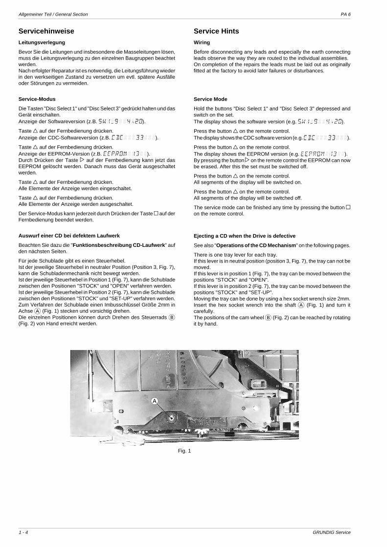
There is one tray lever for each tray.If this lever is in neutral position (position 3, Fig. 7), the tray can not bemoved.If this lever is in position 1 (Fig. 7), the tray can be moved between thepositions "STOCK" and "OPEN".If this lever is in position 2 (Fig. 7), the tray can be moved between thepositions "STOCK" and "SET-UP".Moving the tray can be done by using a hex socket wrench size 2mm.Insert the hex socket wrench into the shaft A (Fig. 1) and turn itcarefully.The positions of the cam wheel B (Fig. 2) can be reached by rotatingit by hand.
Servicehinweise
Leitungsverlegung
Bevor Sie die Leitungen und insbesondere die Masseleitungen lösen,muss die Leitungsverlegung zu den einzelnen Baugruppen beachtetwerden.Nach erfolgter Reparatur ist es notwendig, die Leitungsführung wiederin den werkseitigen Zustand zu versetzen um evtl. spätere Ausfälleoder Störungen zu vermeiden.
Service-Modus
Die Tasten "Disc Select 1" und "Disc Select 3" gedrückt halten und dasGerät einschalten.Anzeige der Softwareversion (z.B. ).
Taste 3 auf der Fernbedienung drücken.Anzeige der CDC-Softwareversion (z.B. ).
Taste 3 auf der Fernbedienung drücken.Anzeige der EEPROM-Version (z.B. ).Durch Drücken der Taste 2 auf der Fernbedienung kann jetzt dasEEPROM gelöscht werden. Danach muss das Gerät ausgeschaltetwerden.
Taste 3 auf der Fernbedienung drücken.Alle Elemente der Anzeige werden eingeschaltet.
Taste 3 auf der Fernbedienung drücken.Alle Elemente der Anzeige werden ausgeschaltet.
Der Service-Modus kann jederzeit durch Drücken der Taste 9 auf derFernbedienung beendet werden.
Auswurf einer CD bei defektem Laufwerk
Beachten Sie dazu die "Funktionsbeschreibung CD-Laufwerk " aufden nächsten Seiten.
Für jede Schublade gibt es einen Steuerhebel.Ist der jeweilige Steuerhebel in neutraler Position (Position 3, Fig. 7),kann die Schubladenmechanik nicht bewegt werden.Ist der jeweilige Steuerhebel in Position 1 (Fig. 7), kann die Schubladezwischen den Positionen "STOCK" und "OPEN" verfahren werden.Ist der jeweilige Steuerhebel in Position 2 (Fig. 7), kann die Schubladezwischen den Positionen "STOCK" und "SET-UP" verfahren werden.Zum Verfahren der Schublade einen Imbusschlüssel Größe 2mm inAchse A (Fig. 1) stecken und vorsichtig drehen.Die einzelnen Positionen können durch Drehen des Steuerrads B(Fig. 2) von Hand erreicht werden.
A
Fig. 1
PA 6 Allgemeiner Teil / General Section
GRUNDIG Service 1 - 5
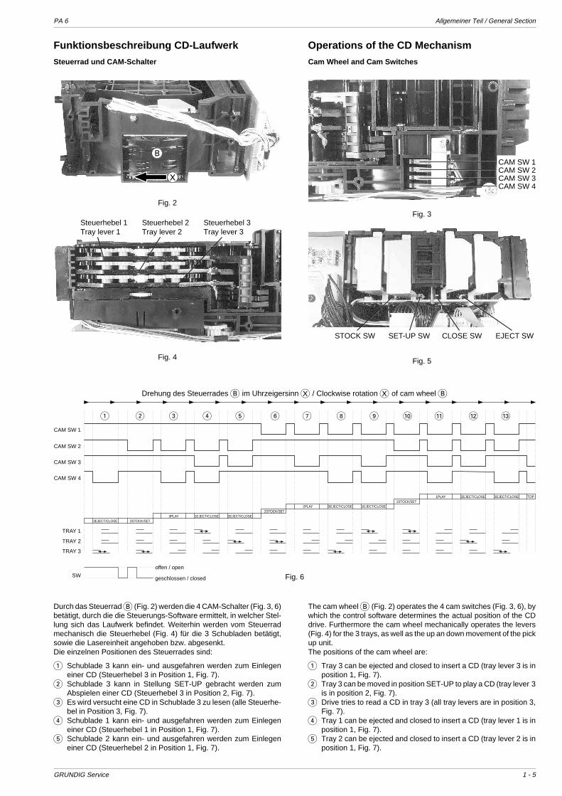
Funktionsbeschreibung CD-Laufwerk
Steuerrad und CAM-Schalter
Operations of the CD Mechanism
Cam Wheel and Cam Switches
Durch das Steuerrad B (Fig. 2) werden die 4 CAM-Schalter (Fig. 3, 6)betätigt, durch die die Steuerungs-Software ermittelt, in welcher Stel-lung sich das Laufwerk befindet. Weiterhin werden vom Steuerradmechanisch die Steuerhebel (Fig. 4) für die 3 Schubladen betätigt,sowie die Lasereinheit angehoben bzw. abgesenkt.Die einzelnen Positionen des Steuerrades sind:
1 Schublade 3 kann ein- und ausgefahren werden zum Einlegeneiner CD (Steuerhebel 3 in Position 1, Fig. 7).
2 Schublade 3 kann in Stellung SET-UP gebracht werden zumAbspielen einer CD (Steuerhebel 3 in Position 2, Fig. 7).
3 Es wird versucht eine CD in Schublade 3 zu lesen (alle Steuerhe-bel in Position 3, Fig. 7).
4 Schublade 1 kann ein- und ausgefahren werden zum Einlegeneiner CD (Steuerhebel 1 in Position 1, Fig. 7).
5 Schublade 2 kann ein- und ausgefahren werden zum Einlegeneiner CD (Steuerhebel 2 in Position 1, Fig. 7).
The cam wheel B (Fig. 2) operates the 4 cam switches (Fig. 3, 6), bywhich the control software determines the actual position of the CDdrive. Furthermore the cam wheel mechanically operates the levers(Fig. 4) for the 3 trays, as well as the up an down movement of the pickup unit.The positions of the cam wheel are:
1 Tray 3 can be ejected and closed to insert a CD (tray lever 3 is inposition 1, Fig. 7).
2 Tray 3 can be moved in position SET-UP to play a CD (tray lever 3is in position 2, Fig. 7).
3 Drive tries to read a CD in tray 3 (all tray levers are in position 3,Fig. 7).
4 Tray 1 can be ejected and closed to insert a CD (tray lever 1 is inposition 1, Fig. 7).
5 Tray 2 can be ejected and closed to insert a CD (tray lever 2 is inposition 1, Fig. 7).
Fig. 5
STOCK SW SET-UP SW CLOSE SW EJECT SW
Fig. 3
CAM SW 1CAM SW 2CAM SW 3CAM SW 4
Fig. 2
B
X
Fig. 4
Steuerhebel 1 Steuerhebel 2 Steuerhebel 3Tray lever 1 Tray lever 2 Tray lever 3
SW
offen / open
geschlossen / closed
CAM SW 1
CAM SW 2
CAM SW 3
CAM SW 4
3EJECT/CLOSE 3STOCK/SET3PLAY 2EJECT/CLOSE1EJECT/CLOSE
2STOCK/SET
1STOCK/SET2PLAY 3EJECT/CLOSE 1EJECT/CLOSE
1PLAY 2EJECT/CLOSE 3EJECT/CLOSE TOP
TRAY 1
TRAY 2
TRAY 3
1 2 3 4 5 6 7 8 9 0 ! @ #
Fig. 6
Drehung des Steuerrades B im Uhrzeigersinn X / Clockwise rotation X of cam wheel B
Allgemeiner Teil / General Section PA 6
1 - 6 GRUNDIG Service
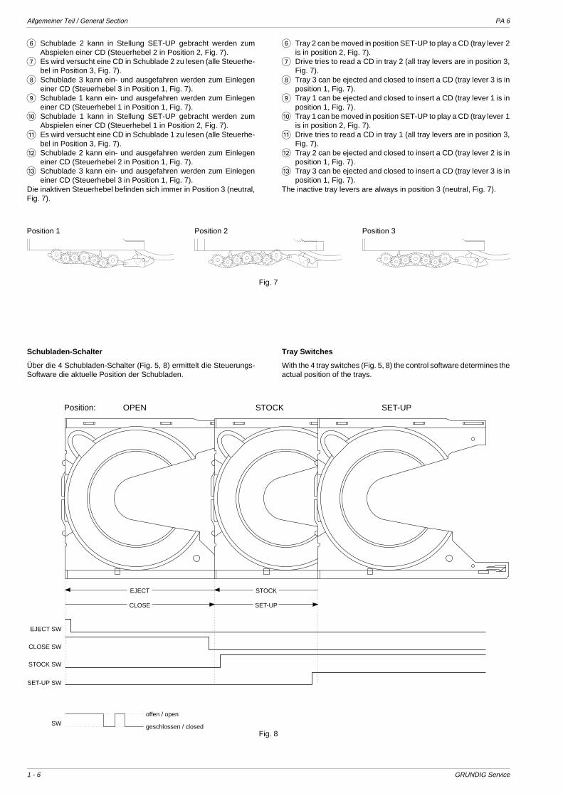
Position 1 Position 2 Position 3
Fig. 7
Schubladen-Schalter
Über die 4 Schubladen-Schalter (Fig. 5, 8) ermittelt die Steuerungs-Software die aktuelle Position der Schubladen.
Tray Switches
With the 4 tray switches (Fig. 5, 8) the control software determines theactual position of the trays.
6 Tray 2 can be moved in position SET-UP to play a CD (tray lever 2is in position 2, Fig. 7).
7 Drive tries to read a CD in tray 2 (all tray levers are in position 3,Fig. 7).
8 Tray 3 can be ejected and closed to insert a CD (tray lever 3 is inposition 1, Fig. 7).
9 Tray 1 can be ejected and closed to insert a CD (tray lever 1 is inposition 1, Fig. 7).
0 Tray 1 can be moved in position SET-UP to play a CD (tray lever 1is in position 2, Fig. 7).
! Drive tries to read a CD in tray 1 (all tray levers are in position 3,Fig. 7).
@ Tray 2 can be ejected and closed to insert a CD (tray lever 2 is inposition 1, Fig. 7).
# Tray 3 can be ejected and closed to insert a CD (tray lever 3 is inposition 1, Fig. 7).
The inactive tray levers are always in position 3 (neutral, Fig. 7).
6 Schublade 2 kann in Stellung SET-UP gebracht werden zumAbspielen einer CD (Steuerhebel 2 in Position 2, Fig. 7).
7 Es wird versucht eine CD in Schublade 2 zu lesen (alle Steuerhe-bel in Position 3, Fig. 7).
8 Schublade 3 kann ein- und ausgefahren werden zum Einlegeneiner CD (Steuerhebel 3 in Position 1, Fig. 7).
9 Schublade 1 kann ein- und ausgefahren werden zum Einlegeneiner CD (Steuerhebel 1 in Position 1, Fig. 7).
0 Schublade 1 kann in Stellung SET-UP gebracht werden zumAbspielen einer CD (Steuerhebel 1 in Position 2, Fig. 7).
! Es wird versucht eine CD in Schublade 1 zu lesen (alle Steuerhe-bel in Position 3, Fig. 7).
@ Schublade 2 kann ein- und ausgefahren werden zum Einlegeneiner CD (Steuerhebel 2 in Position 1, Fig. 7).
# Schublade 3 kann ein- und ausgefahren werden zum Einlegeneiner CD (Steuerhebel 3 in Position 1, Fig. 7).
Die inaktiven Steuerhebel befinden sich immer in Position 3 (neutral,Fig. 7).
EJECT SW
EJECT STOCK
CLOSE SET-UP
CLOSE SW
STOCK SW
SET-UP SW
Position: OPEN STOCK SET-UP
SW
offen / open
geschlossen / closedFig. 8
PA 6 Allgemeiner Teil / General Section
GRUNDIG Service 1 - 7
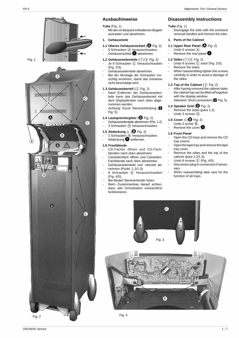
Ausbauhinweise
Tube (Fig. 1)- Mit den im Beipack enthaltenen Bügeln
ausrasten und abnehmen.
1. Gehäuseteile
1.1 Oberes Gehäuserückteil (A Fig. 2)- 5 Schrauben A herausschrauben.- Gehäuserückteil AAAAA abnehmen.
1.2 Gehäuseseitenteile (7/8 Fig. 2)- Je 9 Schrauben C herausschrauben
(Fig. 2/3).- Gehäuseseitenteile abnehmen.- Bei der Montage die Schrauben vor-
sichtig anziehen, damit das Gehäusenicht beschädigt wird.
1.3 Gehäuseoberteil (2 Fig. 2)- Nach Entfernen der Gehäuseseiten-
teile kann das Gehäuseoberteil mitdem Displayfenster nach oben abge-nommen werden.Achtung: Kurze Steckverbindung (6Fig. 5).
1.4 Lautsprechergitter (D Fig. 2)- Gehäuseseitenteile abnehmen (Pkt. 1.2)- 3 Schrauben D herausschrauben.
1.5 Abdeckung S (B Fig. 2)- 2 Schrauben B herausschrauben.- Abdeckung BBBBB entfernen.
1.6 Frontblende- CD-Fächer öffnen und CD-Fach-
blenden nach oben abnehmen.- Cassettenfach öffnen und Cassetten-
Fachblende nach oben abnehmen.- Gehäuseseitenteile und -oberteil ab-
nehmen (Punkt. 1.2/1.3).- 8 Schrauben E herausschrauben
(Fig. 4/5).- Bei Bedarf Steckverbinder lösen.- Beim Zusammenbau darauf achten,
dass alle Schubladen einwandfreifunktionieren.
Disassembly Instructions
Tube (Fig. 1)- Disengage the tube with the enclosed
removal handles and remove the tube.
1. Parts of the Cabinet
1.1 Upper Rear Panel (A Fig. 2)- Undo 5 screws A.- Remove the rear panel AAAAA.
1.2 Sides (7/8 Fig. 2)- Undo 9 screws C each (Fig. 2/3).- Remove the sides.- When reassembling tighten the screws
carefully in order to avoid a damage ofthe sides.
1.3 Top of the Cabinet (2 Fig. 2)- After having removed the cabinet sides
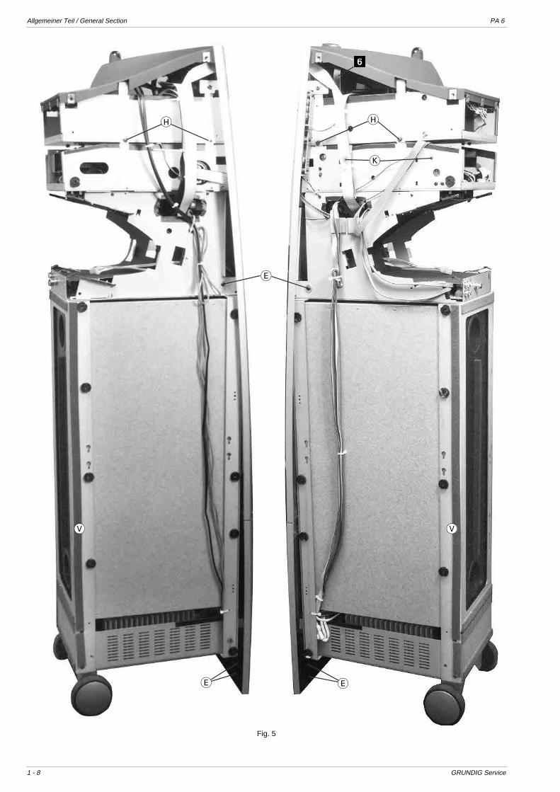
the cabinet top can be lifted off togetherwith the display window.Attention: Short connection (6 Fig. 5).
1.4 Speaker Grid (D Fig. 2)- Remove the sides (para 1.2).- Undo 3 screws D.
1.5 Cover S(B Fig. 2)- Undo 2 screw B.- Remove the cover BBBBB.
1.6 Front Panel- Open the CD trays and remove the CD
tray covers.- Open the tape tray and remove the tape
tray cover.- Remove the sides and the top of the
cabinet (para 1.2/1.3).- Undo 8 screws E (Fig. 4/5).- Disconnect plug in connectors if neces-
sary.- When reassembling take care for the
function of all trays.
A
B
C
C
D
7
8
2
S
Fig. 2
C
Fig. 3
Fig. 1
Fig. 4
E
D
A
B
Allgemeiner Teil / General Section PA 6
1 - 8 GRUNDIG Service
E
EE
Fig. 5
H H
K
VV
6

PA 6 Allgemeiner Teil / General Section
GRUNDIG Service 1 - 9
2. Komponenten
2.1 CD Laufwerk- Gehäuseoberteil entfernen (Punkt 1.3).- Alle Schubladen in Position "STOCK" (Fig. 7) bringen. Beachten
Sie dazu den Servicehinweis "Auswurf einer CD bei defektemLaufwerk" und die Funktionsbeschreibung auf den Seiten 1-4bis 1-6.
- 2 Schrauben F herausschrauben (Fig. 6).- Schraube G (Fig. 7) herausschrauben.- Steckverbinder bei Bedarf abziehen.
Fig. 6
F
G
Fig. 7
2.2 Cassetten-Teil- Alle Gehäuseteile außer dem Lautsprechergitter abnehmen
(Punkt 1).- 4 Schrauben H herausschrauben (Fig. 5).- CD-Teil abnehmen. Beim Einbau CD-Teil so justieren, dass die
CD-Schubladen nach Aufsetzen der Blenden einwandfrei schlie-ßen.
- Bei Bedarf Masseleitung ablöten und Steckverbinder abziehen.Cassetten-Laufwerk:
- 4 Schrauben I herausschrauben (Fig. 8/9).Cassetten-Logik-Platte:
- 2 Schrauben K herausschrauben (Fig. 5).Cassetten-Audio-Platte:
- 4 Abstandshalter L ausrasten (Fig. 9).
I
I
Fig. 8
Fig. 9
L
P
2. Components
2.1 CD Mechanism- Remove the top of the cabinet (para 1.3).- Move all trays to position "STOCK" (Fig. 7). Observe the service
hint "Ejecting a CD when the drive is defective" and the part"Operations of the CD mechanism" on pages 1-4 to 1-6.
- Undo 2 screws F (Fig. 6).- Undo screw G (Fig. 7).- Disconnect plug in connectors if necessary.
2.2 Tape Part- Remove all parts of the cabinet except of the speaker grid (para 1).- Undo 4 screws H (Fig. 5).- Remove the CD part. When reassembling position the CD part so
that after reassembling of the tray covers all trays close perfect.- Unsolder the ground wire and disconnect plug in connectors if
necessary.Tape Mechanism:
- Undo 4 screws I (Fig. 8/9).Tape Logic Board:
- Undo 2 screws K (Fig. 5).Tape Audio Board:
- Release 4 expansion clips L (Fig. 9).

Allgemeiner Teil / General Section PA 6
1 - 10 GRUNDIG Service
2.3 Audio-Platte- Alle Gehäuseteile außer dem Lautsprechergitter abnehmen
(Punkt 1).- 2 Schrauben M herausschrauben (Fig. 10).- Leiterplatte nach hinten aus den Führungen N (Fig. 11) heraus-
ziehen (bei Bedarf Leitungen aus den Kabelführungen aushän-gen).
Fig. 10 Fig. 11
2.3 Tuner-Platte- Gehäuseteile nach Bedarf abnehmen (Punkt 1).- 3 Schrauben O herausschrauben (Fig. 12).
2.4 Chassisoberteil- Gehäuseteile abnehmen (Punkt 1).- 4 Schrauben P herausschrauben (Fig. 8/10).
2.5 System-Transformator- Chassisoberteil abnehmen (Punkt 2.4).- Die Transformatorschrauben sind nun zugänglich.
2.6 Verstärker-Teil- Gehäuseteile abnehmen (Punkt 1).- 4 Schrauben Q herausschrauben (Fig. 13) und Fuß abnehmen.- 2 Schrauben R herausschrauben (Fig. 14).- 6 Schrauben S herausschrauben (Fig. 15).- Bodenwanne mit Verstärkerteil abnehmen.
Fig. 12
Fig. 13 Fig. 14
M
P
O
Fig. 15
Q
N
R
ST
2.3 Audio Board- Remove all parts of the cabinet except of the speaker grid (para 1).- Undo 2 screws M (Fig. 10).- Pull the board out of the guides N (Fig. 11) (unhook the wires from
its guides if necessary).
2.3 Tuner Board- Remove parts of the cabinet on demand (para 1).- Undo 3 screws O (Fig. 12).
2.4 Chassis - Upper Part- Remove the parts of the cabinet (para 1).- Undo 4 screws P (Fig. 8/10).
2.5 System Transformer- Remove the chassis - upper part (para 2.4).- The screws of transformer can now be unscrewed.
2.6 Amplifier Part- Remove all parts of the cabinet (para 1).- Undo 4 screws Q (Fig. 13) and remove the foot.- Undo 2 screws R (Fig. 14).- Undo 6 screws S (Fig. 15).- Remove the amplifier part with its housing.
PA 6 Allgemeiner Teil / General Section
GRUNDIG Service 1 - 11
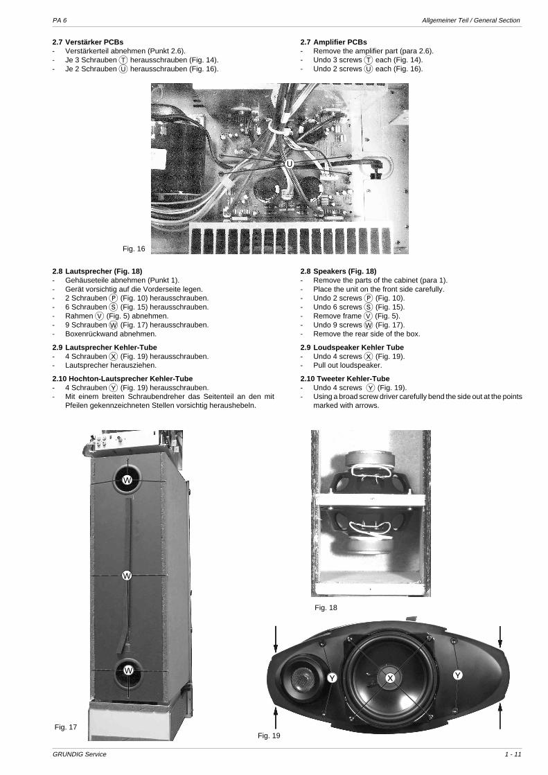
2.7 Verstärker PCBs- Verstärkerteil abnehmen (Punkt 2.6).- Je 3 Schrauben T herausschrauben (Fig. 14).- Je 2 Schrauben U herausschrauben (Fig. 16).
Fig. 16
U
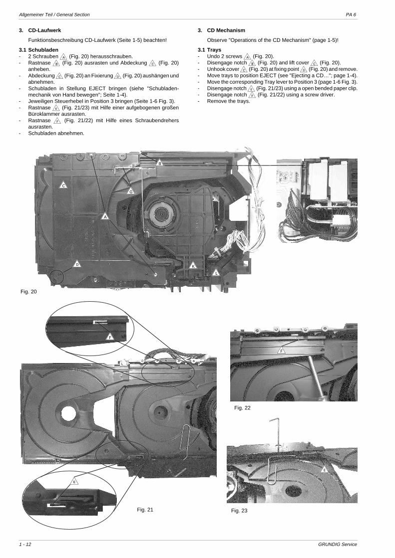
2.8 Lautsprecher (Fig. 18)- Gehäuseteile abnehmen (Punkt 1).- Gerät vorsichtig auf die Vorderseite legen.- 2 Schrauben P (Fig. 10) herausschrauben.- 6 Schrauben S (Fig. 15) herausschrauben.- Rahmen V (Fig. 5) abnehmen.- 9 Schrauben W (Fig. 17) herausschrauben.- Boxenrückwand abnehmen.
2.9 Lautsprecher Kehler-Tube- 4 Schrauben X (Fig. 19) herausschrauben.- Lautsprecher herausziehen.
2.10 Hochton-Lautsprecher Kehler-Tube- 4 Schrauben Y (Fig. 19) herausschrauben.- Mit einem breiten Schraubendreher das Seitenteil an den mit
Pfeilen gekennzeichneten Stellen vorsichtig heraushebeln.
Fig. 17
Fig. 18
W
W
W
Fig. 19
X YY
2.7 Amplifier PCBs- Remove the amplifier part (para 2.6).- Undo 3 screws T each (Fig. 14).- Undo 2 screws U each (Fig. 16).
2.8 Speakers (Fig. 18)- Remove the parts of the cabinet (para 1).- Place the unit on the front side carefully.- Undo 2 screws P (Fig. 10).- Undo 6 screws S (Fig. 15).- Remove frame V (Fig. 5).- Undo 9 screws W (Fig. 17).- Remove the rear side of the box.
2.9 Loudspeaker Kehler Tube- Undo 4 screws X (Fig. 19).- Pull out loudspeaker.
2.10 Tweeter Kehler-Tube- Undo 4 screws Y (Fig. 19).- Using a broad screw driver carefully bend the side out at the points
marked with arrows.
Allgemeiner Teil / General Section PA 6
1 - 12 GRUNDIG Service
3. CD-Laufwerk
Funktionsbeschreibung CD-Laufwerk (Seite 1-5) beachten!
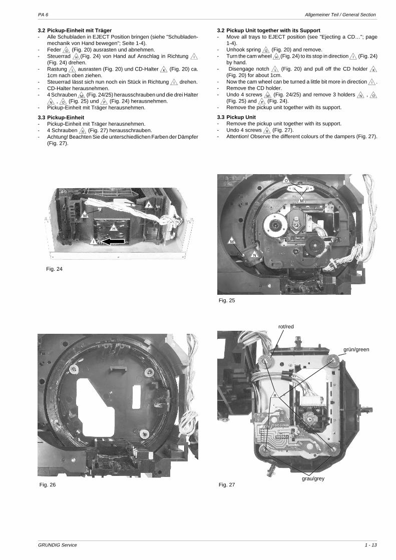
3.1 Schubladen- 2 Schrauben a (Fig. 20) herausschrauben.- Rastnase b (Fig. 20) ausrasten und Abdeckung c (Fig. 20)
anheben.- Abdeckung c (Fig. 20) an Fixierung d (Fig. 20) aushängen und
abnehmen.- Schubladen in Stellung EJECT bringen (siehe "Schubladen-
mechanik von Hand bewegen"; Seite 1-4).- Jeweiligen Steuerhebel in Position 3 bringen (Seite 1-6 Fig. 3).- Rastnase e (Fig. 21/23) mit Hilfe einer aufgebogenen großen
Büroklammer ausrasten.- Rastnase f (Fig. 21/22) mit Hilfe eines Schraubendrehers
ausrasten.- Schubladen abnehmen.
Fig. 20
Fig. 21
Fig. 22
Fig. 23
f
e
e
f
a
d
c
b
g
kl
3. CD Mechanism
Observe "Operations of the CD Mechanism" (page 1-5)!
3.1 Trays- Undo 2 screws a (Fig. 20).- Disengage notch b (Fig. 20) and lift cover c (Fig. 20).- Unhook cover c (Fig. 20) at fixing point d (Fig. 20) and remove.- Move trays to position EJECT (see "Ejecting a CD…"; page 1-4).- Move the corresponding Tray lever to Position 3 (page 1-6 Fig. 3).- Disengage notch e (Fig. 21/23) using a open bended paper clip.- Disengage notch f (Fig. 21/22) using a screw driver.- Remove the trays.
PA 6 Allgemeiner Teil / General Section
GRUNDIG Service 1 - 13
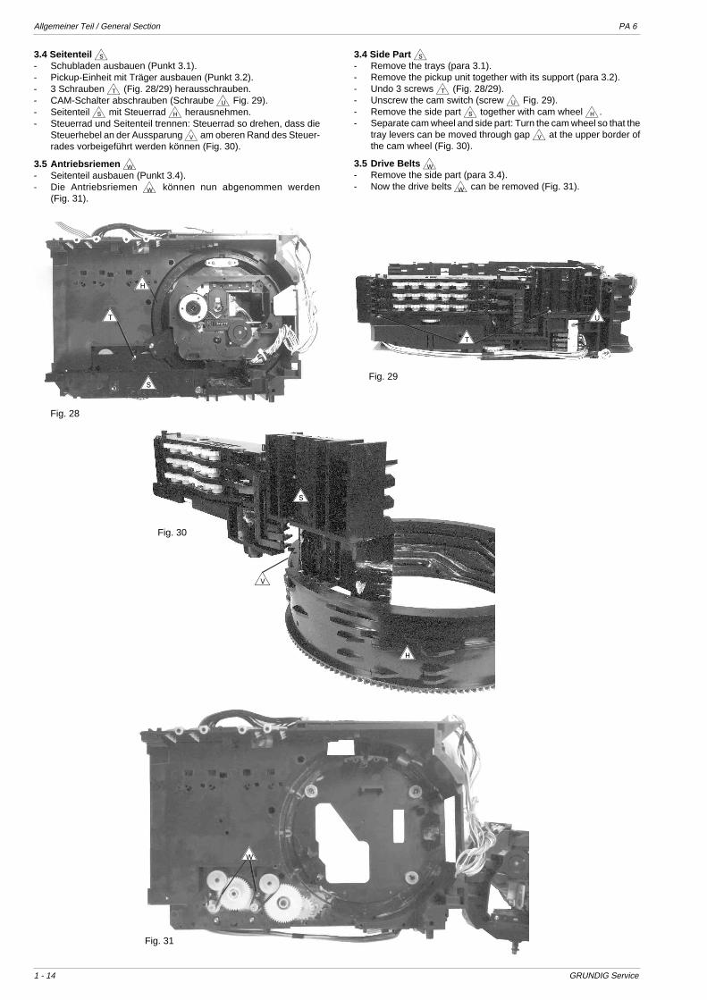
3.2 Pickup-Einheit mit Träger- Alle Schubladen in EJECT Position bringen (siehe "Schubladen-
mechanik von Hand bewegen"; Seite 1-4).- Feder g (Fig. 20) ausrasten und abnehmen.- Steuerrad h(Fig. 24) von Hand auf Anschlag in Richtung i
(Fig. 24) drehen.- Rastung l ausrasten (Fig. 20) und CD-Halter k (Fig. 20) ca.
1cm nach oben ziehen.- Steuerrad lässt sich nun noch ein Stück in Richtung i drehen.- CD-Halter herausnehmen.- 4 Schrauben m (Fig. 24/25) herausschrauben und die drei Halter
n , o (Fig. 25) und p (Fig. 24) herausnehmen.- Pickup-Einheit mit Träger herausnehmen.
3.3 Pickup-Einheit- Pickup-Einheit mit Träger herausnehmen.- 4 Schrauben r (Fig. 27) herausschrauben.- Achtung! Beachten Sie die unterschiedlichen Farben der Dämpfer
(Fig. 27).
Fig. 24
Fig. 25
h
p
m
o
n
m
m
Fig. 26 Fig. 27
r
rot/red
grün/green
grau/grey
3.2 Pickup Unit together with its Support- Move all trays to EJECT position (see "Ejecting a CD…"; page
1-4).- Unhook spring g (Fig. 20) and remove.- Turn the cam wheel h(Fig. 24) to its stop in direction i (Fig. 24)
by hand.- Disengage notch l (Fig. 20) and pull off the CD holder k
(Fig. 20) for about 1cm.- Now the cam wheel can be turned a little bit more in direction i.- Remove the CD holder.- Undo 4 screws m (Fig. 24/25) and remove 3 holders n , o
(Fig. 25) and p (Fig. 24).- Remove the pickup unit together with its support.
3.3 Pickup Unit- Remove the pickup unit together with its support.- Undo 4 screws r (Fig. 27).- Attention! Observe the different colours of the dampers (Fig. 27).
i
Allgemeiner Teil / General Section PA 6
1 - 14 GRUNDIG Service
3.4 Seitenteil s- Schubladen ausbauen (Punkt 3.1).- Pickup-Einheit mit Träger ausbauen (Punkt 3.2).- 3 Schrauben t (Fig. 28/29) herausschrauben.- CAM-Schalter abschrauben (Schraube u Fig. 29).- Seitenteil s mit Steuerrad h herausnehmen.- Steuerrad und Seitenteil trennen: Steuerrad so drehen, dass die
Steuerhebel an der Aussparung v am oberen Rand des Steuer-rades vorbeigeführt werden können (Fig. 30).
3.5 Antriebsriemen w- Seitenteil ausbauen (Punkt 3.4).- Die Antriebsriemen w können nun abgenommen werden
(Fig. 31).
Fig. 28
s
t
t
u
Fig. 31
Fig. 29
h
s
h
Fig. 30
v
3.4 Side Part s- Remove the trays (para 3.1).- Remove the pickup unit together with its support (para 3.2).- Undo 3 screws t (Fig. 28/29).- Unscrew the cam switch (screw u Fig. 29).- Remove the side part s together with cam wheel h.- Separate cam wheel and side part: Turn the cam wheel so that the
tray levers can be moved through gap v at the upper border ofthe cam wheel (Fig. 30).
3.5 Drive Belts w- Remove the side part (para 3.4).- Now the drive belts w can be removed (Fig. 31).
w
PA 6 Allgemeiner Teil / General Section
GRUNDIG Service 1 - 15
C
C
C
C
N
N
O
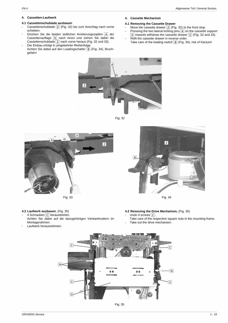
4. Cassetten-Laufwerk
4.1 Cassettenschublade ausbauen- Cassettenschublade Z (Fig. 32) bis zum Anschlag nach vorne
schieben.- Drücken Sie die beiden seitlichen Arretierungszapfen A der
Cassettenauflage X nach innen und ziehen Sie dabei dieCassettenschublade Z nach vorne heraus (Fig. 32 und 33).
- Der Einbau erfolgt in umgekehrter Reihenfolge.Achten Sie dabei auf den Loadingschalter B (Fig. 34), Bruch-gefahr!
4. Cassette Mechanism
4.1 Removing the Cassette Drawer- Move the cassette drawer Z (Fig. 32) to the front stop.- Pressing the two lateral locking pins A on the cassette support
X inwards withdraw the cassette drawer Z (Fig. 32 and 33).- Refit the cassette drawer in reverse order.
Take care of the loading switch B (Fig. 34), risk of fracture!
Fig. 32
Fig. 33 Fig. 34
4.2 Laufwerk ausbauen , (Fig. 35)- 4 Schrauben C herausdrehen.
Achten Sie dabei auf die dazugehörigen Vierkantmuttern imMontagerahmen.
- Laufwerk herausnehmen.
4.2 Removing the Drive Mechanism, (Fig. 35)- Undo 4 screws C.
Take care of the respective square nuts in the mounting frame.- Take out the drive mechanism.
Fig. 35
A
Z
A
X
Z Z
B

Allgemeiner Teil / General Section PA 6
1 - 16 GRUNDIG Service
4.4 Andruckrollenhebel auswechseln (Fig. 37 / 38)- Laufwerk ausbauen (Punkt. 4.2)- Rastnase I nach außen drücken und Andruckrollenhebel J,
K nach oben abziehen.
4.4 Replacing the Presure Roller Levers (Fig. 37 / 38)- Remove the drive mechanism (para 4.2).- Press the locking lug I outwards and pull off the pressure roller
levers J, K.
4.5 Schwungräder auswechseln- Laufwerk ausbauen (Punkt. 4.2)- Ölfangscheiben L und M abziehen (Fig. 36).- 3 Schrauben N herausdrehen und Laufwerkabdeckung O
abnehmen (Fig. 35).- Riemen P und Q abnehmen (Fig. 39).- Schwungräder R und S herausnehmen.
Nach dem Einbau der Schwungräder müssen die Capstanwellenmit Spiritus oder Reinigungsbenzin gereinigt werden.
4.6 Laufwerkleiterplatte ausbauen (Fig. 40)- 2 Schrauben T herausdrehen und Haltewinkel U abnehmen.- Schraube V herausdrehen.- Beide Servomagnete W ablöten.- Leiterplatte vorsichtig abnehmen.
4.5 Replacing the Flywheels- Remove the drive mechanism (para 4.2).- Pull off the oil seals L and M (Fig. 36).- Undo 3 screws N and take the cover O off the drive mechanism
(Fig. 35).- Remove the belts P and Q (Fig. 39).- Take out the flywheels R and S.
After having fitted the new flywheels the capstans must becleaned with spirit or cleaning benzine.
4.6 Removing the Drive Mechanism Circuit Board (Fig. 40)- Undo 2 screws T and take out bracket U.- Undo screw V.- Unsolder both servo magnets W.- Remove the circuit board carefully.
Fig. 37
Fig. 36
Fig. 40
Fig. 38
D
L E FG H M
I
J
I
Fig. 39
K
Q
P
R S
T U W U V W U T
4.3 Kopfträger ausbauen (Fig. 36)- Laufwerk ausbauen (Punkt. 4.2)- 2 Schrauben D herausdrehen.- Achtung! Die Schrauben E und F nicht verdrehen, sie dienen
zur Kopfspalt- und Bandlaufeinstellung.- Kopfleitungen ablöten (evtl. notieren)- Kopfträger G (mit Kombikopf H) abnehmen.
4.3 Removing the Head Base (Fig. 36)- Remove the drive mechanism (para 4.2).- Undo 2 screws D.- Warning! Do not turn the screws E and F. They are used to
adjust the head gap position and the tape transport.- Unsolder the head connecting leads (mark them, if necessary).- Remove the head base G (with combi head H).

PA 6 Allgemeiner Teil / General Section
GRUNDIG Service 1 - 17
Fühlhebel - BSensing lever - B
Fühlhebel - BSensing lever - B
(Normal) (Reverse)
SCHIEBER - ASLIDER - A
FÜHLHEBEL - BSENSING LEVER - B
KOPFLEHRE 401HEAD GAUGE 401
KopflehreHead gauge
Fühlhebel - BSensing lever - B
KopflehreHead gauge
Fig. 41 Fig. 42
Fig. 44Fig. 43 Fig. 45
4.7 BandlaufeinstellungDie Bandlaufeinstellung wird notwendig nach einem Wechseldes Kombikopfes H bzw. des Kopfträgers G (Fig. 36).Prüfen Sie den Bandlauf (Bandführungshöhe) mit der Kopflehre401 (Fig. 41) und einer Bandlaufcassette. Der Schieber A derKopflehre ist bei diesem Gerät ohne Funktion.
- 4 Schrauben 1 herausdrehen und Cassettenschachthalter 2abnehmen (Fig. 42).
- 2 Federn 3 aushängen und Klappe 4 abnehmen (Fig. 42).- Cassettenschublade bis zum Anschlag ganz einfahren.- Legen Sie die Kopflehre auf.
Achten Sie dabei auf die Bandselectoren (Cassettenfühler) undeine korrekte Auflage der Kopflehre.
- Gerätefunktion: Start B oder Start A, d.h. der Kopfschlitten wirdin die Richtung der Kopflehre bewegt.
- Führen Sie den Fühlhebel B der Kopflehre zur Bandführungs-gabel 5 (Fig. 43) bzw. 6 (Fig. 44).
- Einstellschrauben 7 so verdrehen, dass sich der Fühlhebel B leichtzwischen den Bandführungen 5 bzw. 6 bewegen lässt. Sind diebeiden Bandführungen in der Höhe eingestellt, so muss die Unter-kante des Fühlhebels B sich auch leicht über die Unterkante derKopfgabel 8 (Fig. 45) des Kombikopfes schieben lassen (Laufrich-tung B und A). Der Kombikopf muss dabei senkrecht stehen unddarf keine Neigung aufweisen. Der Kopfspiegel muß im rechtenWinkel zum Chassis bzw. parallel zur Tonwelle stehen.
- Gerät auf Stop 9 schalten.- Kopflehre abnehmen.
4.7 Adjustment of the Tape TransportAdjustment of the tape transport is necessary after changing thecombi head H or the head base G (Fig. 36).Check the tape path (tape guiding height) with the head gauge401 (Fig. 41) and a tape transport test cassette. The slider A doesnot have any function with this set.
- Undo 4 screws 1 and remove the cassette compartment holder2 (Fig. 42).
- Unhook 2 springs 3 and remove the flap 4 (Fig. 42).- Push the cassette drawer in until it reaches the rear end stop.- Place the head gauge on to the drive mechanism.
Take care of the tape selectors (cassette sensing levers) andensure that the head gauge is correctly positioned.
- Press Start B or Start A, i.e. the head base is moved in thedirection of the head gauge.
- Move the sensing lever B of the head gauge towards the tapeguide 5 (Fig. 43) or 6 (Fig. 44).
- Turn the adjustment screws 7 so that the sensing lever B movessmoothly between the tape guides 5 or 6. When the height ofboth tape guides is correctly adjusted, it must also be possible tomove the lower edge of the sensing lever B smoothly over thelower edge of the head guide 8 (Fig. 45) (direction B and A).The combi head must be in vertical position and must not be tilted.The head face must be perpendicular to the chassis or in parallelwith the capstan.
- Press Stop 9.- Remove the head gauge.
Vor der Prüfung mit der Bandlaufcassette muss das Laufwerkangeschlossen und das Gerät elektrisch betriebsbereit sein.Die Andruckrolle, die Tonwelle und der Kombikopf müssen freivon Bandabrieb und Schmutz sein.
- Bandlaufcassette (z.B. 457) einlegen.- Durch Umspulen der Bandlaufcassette erzeugen Sie einen ge-
räteeigenen Bandwickel.- Gerätefunktion: Start B oder Start A. Beim Durchlauf der
Bandlaufcassette darf das Band nicht an der oberen oder unte-ren Kante der Kopfgabel des Kombikopfes umknicken. Einegeringe Korrektur des Bandlaufes ist möglich durch Verdrehender Schrauben 7 (Fig. 43 / 44).Nach der Bandlaufeinstellung ist mit einer Testbandcassette dieSenkrechtstellung (Azimut) des Kombikopfes zu prüfen undwenn notwendig, mit den Kopfschrauben E oder F nachzu-justieren, siehe >Abgleichvorschriften <.
For carrying out the test with the tape transport test cassette, thedrive mechanism must be connected and the recorder must beelectrically operable.The pressure roller, the capstan and the combi head must be freeof abraded tape material and dirt.
- Insert the test cassette (e.g. 457).- Wind the test cassette to produce a typical tape roll of this machine.- Select function: Start B or Start A. During this operation the
tape must not bend on the upper or lower edge of the guide forkof the combi head. The tape transport can be corrected by a smallamout by turning the screws 7 (Fig. 43 / 44).After adjustment of the tape transport with a test cassette checkthe head gap position (Azimuth) of the combi head and ifnecessary re-adjust with the head screws E or F as describedin chapter >Adjustment Procedures <.
1 12 43
7
5
7
6
8
E F
(Normal)
Allgem
einer Teil / G
eneral Section
PA
6
1 - 18G
RU
ND
IG S
ervice
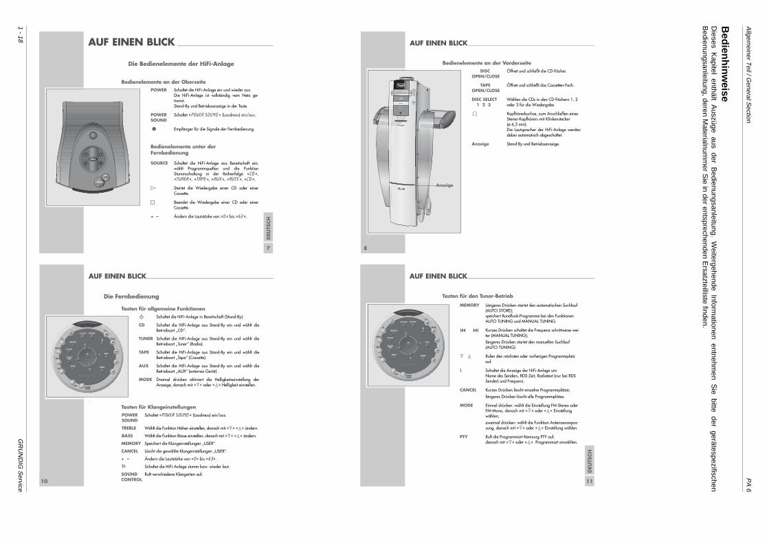
Die Bedienelemente der HiFi-Anlage
Bedienelemente an der OberseitePOWER Schaltet die HiFi-Anlage ein und wieder aus.
Die HiFi-Anlage ist vollständig vom Netz ge-trennt.Stand-By und Betriebsanzeige in der Taste.
POWER Schaltet »POWER SOUND « (Loudness) ein/aus.SOUND
• Empfänger für die Signale der Fernbedienung.
Bedienelemente unter der Fernbedienung
SOURCE Schaltet die HiFi-Anlage aus Bereitschaft ein;wählt Programmquellen und die FunktionStummschaltung in der Reihenfolge »CD «,»TUNER «, »TAPE «, »AUX «, »MUTE «, »CD «.
E Startet die Wiedergabe einer CD oder einer Cassette.
§§ Beendet die Wiedergabe einer CD oder einerCassette.
+ – Ändern die Lautstärke von »0« bis »63 «.
POWER
POWERSOUND
SOURCE
DEU
TSCH
7
AUF EINEN BLICK _____________________________________________________ AUF EINEN BLICK______________________________________________________________________
8
Bedienelemente an der VorderseiteDISC Öffnet und schließt die CD-Fächer.
OPEN/CLOSE
TAPE Öffnet und schließt das Cassetten-Fach.OPEN/CLOSE
DISC SELECT Wählen die CDs in den CD-Fächern 1, 2 1 2 3 oder 3 für die Wiedergabe.
0 Kopfhörerbuchse, zum Anschließen einesStereo-Kopfhörers mit Klinkenstecker (ø 6,3 mm).Die Lautsprecher der HiFi-Anlage werdendabei automatisch abgeschaltet.
Anzeige Stand-By und Betriebsanzeige.
DISCOPEN/CLOSE
TAPEOPEN/CLOSE
3
2
1
DISC SELECT
1 2 3
U
B NR
Anzeige
10
AUF EINEN BLICK______________________________________________________________________
Die Fernbedienung
Tasten für allgemeine Funktionen99 Schaltet die HiFi-Anlage in Bereitschaft (Stand-By).
CD Schaltet die HiFi-Anlage aus Stand-By ein und wählt dieBetriebsart „CD“.
TUNER Schaltet die HiFi-Anlage aus Stand-By ein und wählt dieBetriebsart „Tuner“ (Radio).
TAPE Schaltet die HiFi-Anlage aus Stand-By ein und wählt dieBetriebsart „Tape“ (Cassette).
AUX Schaltet die HiFi-Anlage aus Stand-By ein und wählt dieBetriebsart „AUX“ (externes Gerät).
MODE Dreimal drücken aktiviert die Helligkeitseinstellung derAnzeige, danach mit »1« oder »2« Helligkeit einstellen.
Tasten für KlangeinstellungenPOWER Schaltet »POWER SOUND « (Loudness) ein/aus.SOUND
TREBLE Wählt die Funktion Höhen einstellen, danach mit »1« »2« ändern.
BASS Wählt die Funktion Bässe einstellen; danach mit »1« »2« ändern.
MEMORY Speichert die Klangeinstellungen „USER”.
CANCEL Löscht die gewählte Klangeinstellungen „USER”.
+ – Ändern die Lautstärke von »0« bis »63«.
a Schaltet die HiFi-Anlage stumm bzw. wieder laut.
SOUND Ruft verschiedene Klangarten auf.CONTROL
CD-COPY RECORD
MEMORY
CANCEL
SOUNDCTRL
MODE TREBLE
BASS
CD
TUNER
TAPE
AUX
DISCPOWERSOUND
PTY
PAUSE
8
111
DEU
TSCH
11
AUF EINEN BLICK______________________________________________________________________
Tasten für den Tuner-Betrieb
MEMORY Längeres Drücken startet den automatischen Suchlauf(AUTO STORE);speichert Rundfunk-Programme bei den FunktionenAUTO TUNING und MANUAL TUNING.
8 9 Kurzes Drücken schaltet die Frequenz schrittweise wei-ter (MANUAL TUNING);
längeres Drücken startet den manuellen Suchlauf(AUTO TUNING).
1 2 Rufen den nächsten oder vorherigen Programmplatzauf.
i Schaltet die Anzeige der HiFi-Anlage um:Name des Senders, RDS-Zeit, Radiotext (nur bei RDSSender) und Frequenz.
CANCEL Kurzes Drücken löscht einzelne Programmplätze;
längeres Drücken löscht alle Programmplätze.
MODE Einmal drücken: wählt die Einstellung FM-Stereo oderFM-Mono, danach mit »1« oder »2« Einstellungwählen;
zweimal drücken: wählt die Funktion Antennenanpas-sung, danach mit »1« oder »2« Einstellung wählen.
PTY Ruft die Programmart-Kennung PTY auf,danach mit »1« oder »2« Programmart anwählen.
CD-COPY RECORD
MEMORY
CANCEL
SOUNDCTRL
MODE TREBLE
BASS
CD
TUNER
TAPE
AUX
DISCPOWERSOUND
PTY
PAUSE
8
111
Bedienhinw
eiseD
ieses Kapitel enthält A
uszüge aus der Bedienungsanleitung. W
eitergehende Informationen entnehm
en Sie bitte der gerätespezifischen
Bedienungsanleitung, deren M
aterialnumm
er Sie in der entsprechenden E
rsatzteilliste finden.
PA
6A
llgemeiner T
eil / General S
ection
GR
UN
DIG
Service
1 - 19
AUF EINEN BLICK______________________________________________________________________
12
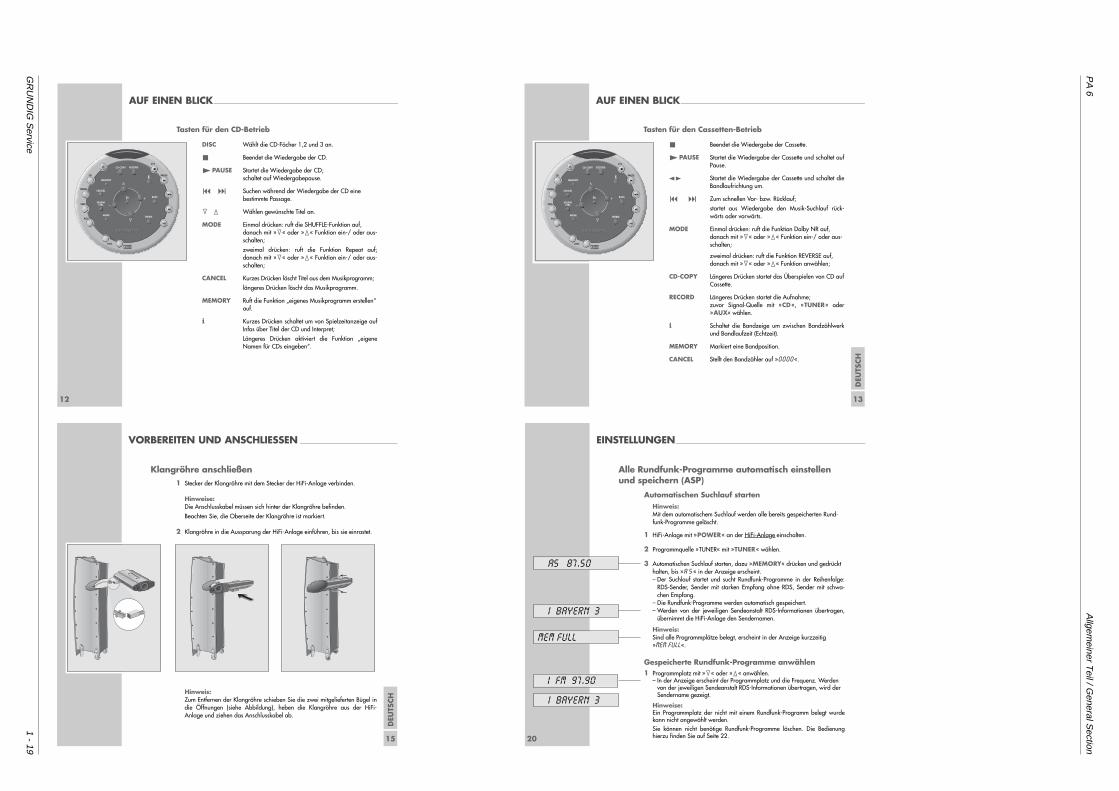
Tasten für den CD-Betrieb
DISC Wählt die CD-Fächer 1,2 und 3 an.
5 Beendet die Wiedergabe der CD.
4PAUSE Startet die Wiedergabe der CD; schaltet auf Wiedergabepause.
8 9 Suchen während der Wiedergabe der CD einebestimmte Passage.
1 2 Wählen gewünschte Titel an.
MODE Einmal drücken: ruft die SHUFFLE-Funktion auf, danach mit »1« oder »2« Funktion ein-/ oder aus-schalten;
zweimal drücken: ruft die Funktion Repeat auf;danach mit »1« oder »2« Funktion ein-/ oder aus-schalten;
CANCEL Kurzes Drücken löscht Titel aus dem Musikprogramm;
längeres Drücken löscht das Musikprogramm.
MEMORY Ruft die Funktion „eigenes Musikprogramm erstellen“auf.
i Kurzes Drücken schaltet um von Spielzeitanzeige aufInfos über Titel der CD und Interpret;
Längeres Drücken aktiviert die Funktion „eigeneNamen für CDs eingeben“.
CD-COPY RECORD
MEMORY
CANCEL
SOUNDCTRL
MODE TREBLE
BASS
CD
TUNER
TAPE
AUX
DISCPOWERSOUND
PTY
PAUSE
8
111
AUF EINEN BLICK______________________________________________________________________
DEU
TSCH
13
Tasten für den Cassetten-Betrieb
5 Beendet die Wiedergabe der Cassette.
4PAUSE Startet die Wiedergabe der Cassette und schaltet aufPause.
z t Startet die Wiedergabe der Cassette und schaltet dieBandlaufrichtung um.
8 9 Zum schnellen Vor- bzw. Rücklauf;
startet aus Wiedergabe den Musik-Suchlauf rück-wärts oder vorwärts.
MODE Einmal drücken: ruft die Funktion Dolby NR auf,danach mit »1« oder »2« Funktion ein-/ oder aus-schalten;
zweimal drücken: ruft die Funktion REVERSE auf,danach mit »1« oder »2« Funktion anwählen;
CD-COPY Längeres Drücken startet das Überspielen von CD aufCassette.
RECORD Längeres Drücken startet die Aufnahme;zuvor Signal-Quelle mit »CD«, »TUNER« oder»AUX« wählen.
i Schaltet die Bandzeige um zwischen Bandzählwerkund Bandlaufzeit (Echtzeit).
MEMORY Markiert eine Bandposition.
CANCEL Stellt den Bandzähler auf »0000«.
CD-COPY RECORD
MEMORY
CANCEL
SOUNDCTRL
MODE TREBLE
BASS
CD
TUNER
TAPE
AUX
DISCPOWERSOUND
PTY
PAUSE
8
111
DEU
TSCH
15
VORBEREITEN UND ANSCHLIESSEN _____________________________________
Klangröhre anschließen1 Stecker der Klangröhre mit dem Stecker der HiFi-Anlage verbinden.
Hinweise: Die Anschlusskabel müssen sich hinter der Klangröhre befinden.
Beachten Sie, die Oberseite der Klangröhre ist markiert.
2 Klangröhre in die Aussparung der HiFi-Anlage einführen, bis sie einrastet.
Hinweis: Zum Entfernen der Klangröhre schieben Sie die zwei mitgelieferten Bügel indie Öffnungen (siehe Abbildung), heben die Klangröhre aus der HiFi-Anlage und ziehen das Anschlusskabel ab.
TOP SIDE
OBEN
20
Alle Rundfunk-Programme automatisch einstellenund speichern (ASP)
Automatischen Suchlauf startenHinweis:Mit dem automatischem Suchlauf werden alle bereits gespeicherten Rund-funk-Programme gelöscht.
1 HiFi-Anlage mit »POWER« an der HiFi-Anlage einschalten.
2 Programmquelle »TUNER« mit »TUNER« wählen.
3 Automatischen Suchlauf starten, dazu »MEMORY« drücken und gedrückthalten, bis »A S« in der Anzeige erscheint.– Der Suchlauf startet und sucht Rundfunk-Programme in der Reihenfolge:
RDS-Sender, Sender mit starken Empfang ohne RDS, Sender mit schwa-chen Empfang.
– Die Rundfunk-Programme werden automatisch gespeichert.– Werden von der jeweiligen Sendeanstalt RDS-Informationen übertragen,
übernimmt die HiFi-Anlage den Sendernamen.
Hinweis:Sind alle Programmplätze belegt, erscheint in der Anzeige kurzzeitig»MEM FULL«.
Gespeicherte Rundfunk-Programme anwählen1 Programmplatz mit »1« oder »2« anwählen.
– In der Anzeige erscheint der Programmplatz und die Frequenz. Werdenvon der jeweiligen Sendeanstalt RDS-Informationen übertragen, wird derSendername gezeigt.
Hinweise:Ein Programmplatz der nicht mit einem Rundfunk-Programm belegt wurdekann nicht angewählt werden.Sie können nicht benötige Rundfunk-Programme löschen. Die Bedienunghierzu finden Sie auf Seite 22.
EINSTELLUNGEN________________________________________________________________________
AS 87.50
MEM FULL
I FM 97.90
I BAYERN 3
I BAYERN 3
Allgem
einer Teil / G
eneral Section
PA
6
1 - 20G
RU
ND
IG S
ervice
EINSTELLUNGEN________________________________________________________________________
DEU
TSCH
21
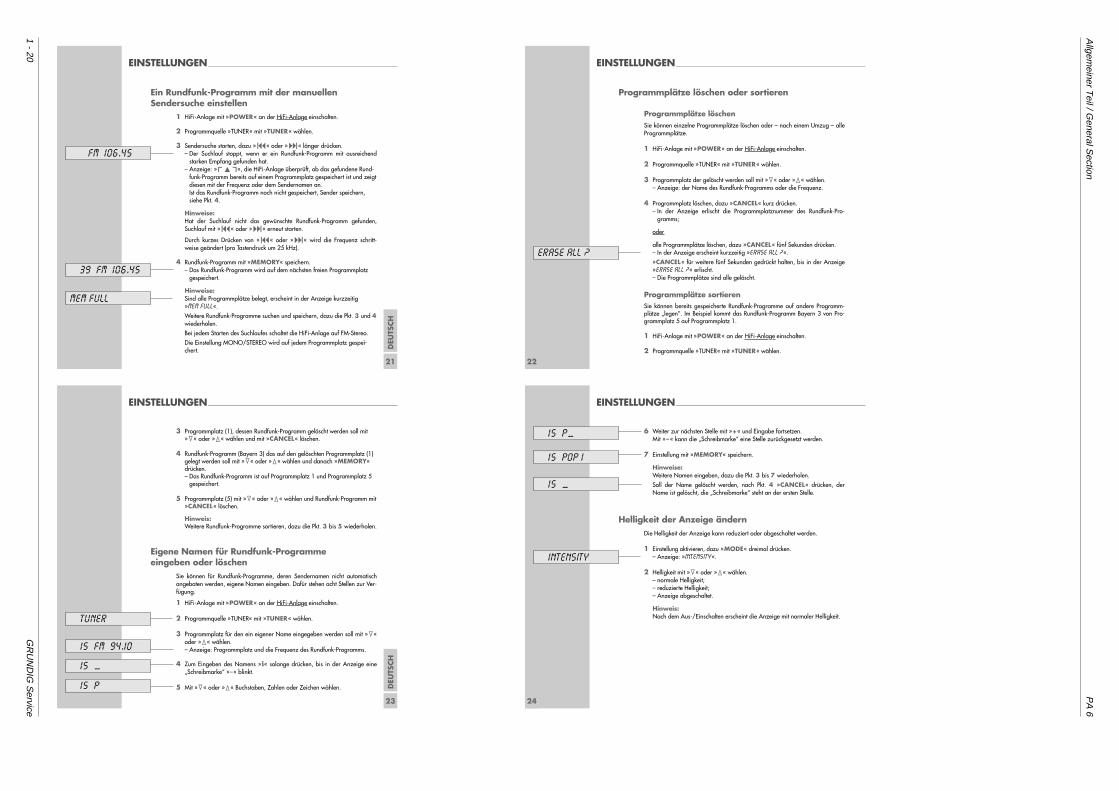
Ein Rundfunk-Programm mit der manuellen Sendersuche einstellen
1 HiFi-Anlage mit »POWER« an der HiFi-Anlage einschalten.
2 Programmquelle »TUNER« mit »TUNER« wählen.
3 Sendersuche starten, dazu »8« oder »9« länger drücken.– Der Suchlauf stoppt, wenn er ein Rundfunk-Programm mit ausreichend
starken Empfang gefunden hat.– Anzeige: »%«, die HiFi-Anlage überprüft, ob das gefundene Rund-
funk-Programm bereits auf einem Programmplatz gespeichert ist und zeigtdiesen mit der Frequenz oder dem Sendernamen an.Ist das Rundfunk-Programm noch nicht gespeichert, Sender speichern,siehe Pkt. 4.
Hinweise:Hat der Suchlauf nicht das gewünschte Rundfunk-Programm gefunden,Suchlauf mit »8« oder »9« erneut starten.
Durch kurzes Drücken von »8« oder »9« wird die Frequenz schritt-weise geändert (pro Tastendruck um 25 kHz).
4 Rundfunk-Programm mit »MEMORY« speichern.– Das Rundfunk-Programm wird auf dem nächsten freien Programmplatz
gespeichert.
Hinweise:Sind alle Programmplätze belegt, erscheint in der Anzeige kurzzeitig »MEM FULL«.
Weitere Rundfunk-Programme suchen und speichern, dazu die Pkt. 3 und 4wiederholen.
Bei jedem Starten des Suchlaufes schaltet die HiFi-Anlage auf FM-Stereo.
Die Einstellung MONO/STEREO wird auf jedem Programmplatz gespei-chert.
MEM FULL
FM 106.45
39 FM 106.45
22
EINSTELLUNGEN________________________________________________________________________
Programmplätze löschen oder sortieren
Programmplätze löschenSie können einzelne Programmplätze löschen oder – nach einem Umzug – alleProgrammplätze.
1 HiFi-Anlage mit »POWER« an der HiFi-Anlage einschalten.
2 Programmquelle »TUNER« mit »TUNER« wählen.
3 Programmplatz der gelöscht werden soll mit »1« oder »2« wählen.– Anzeige: der Name des Rundfunk-Programms oder die Frequenz.
4 Programmplatz löschen, dazu »CANCEL« kurz drücken.– In der Anzeige erlischt die Programmplatznummer des Rundfunk-Pro-
gramms;
oder
alle Programmplätze löschen, dazu »CANCEL« fünf Sekunden drücken.– In der Anzeige erscheint kurzzeitig »ERASE ALL ?«.
»CANCEL« für weitere fünf Sekunden gedrückt halten, bis in der Anzeige»ERASE ALL ?« erlischt.– Die Programmplätze sind alle gelöscht.
Programmplätze sortierenSie können bereits gespeicherte Rundfunk-Programme auf andere Programm-plätze „legen”. Im Beispiel kommt das Rundfunk-Programm Bayern 3 von Pro-grammplatz 5 auf Programmplatz 1.
1 HiFi-Anlage mit »POWER« an der HiFi-Anlage einschalten.
2 Programmquelle »TUNER« mit »TUNER« wählen.
ERASE ALL ?
DEU
TSCH
23
EINSTELLUNGEN________________________________________________________________________
3 Programmplatz (1), dessen Rundfunk-Programm gelöscht werden soll mit»1« oder »2« wählen und mit »CANCEL« löschen.
4 Rundfunk-Programm (Bayern 3) das auf den gelöschten Programmplatz (1)gelegt werden soll mit »1« oder »2« wählen und danach »MEMORY«drücken.– Das Rundfunk-Programm ist auf Programmplatz 1 und Programmplatz 5
gespeichert.
5 Programmplatz (5) mit »1« oder »2« wählen und Rundfunk-Programm mit»CANCEL« löschen.
Hinweis:Weitere Rundfunk-Programme sortieren, dazu die Pkt. 3 bis 5 wiederholen.
Eigene Namen für Rundfunk-Programme eingeben oder löschen
Sie können für Rundfunk-Programme, deren Sendernamen nicht automatischangeboten werden, eigene Namen eingeben. Dafür stehen acht Stellen zur Ver-fügung.
1 HiFi-Anlage mit »POWER« an der HiFi-Anlage einschalten.
2 Programmquelle »TUNER« mit »TUNER« wählen.
3 Programmplatz für den ein eigener Name eingegeben werden soll mit »1«oder »2« wählen.– Anzeige: Programmplatz und die Frequenz des Rundfunk-Programms.
4 Zum Eingeben des Namens »i« solange drücken, bis in der Anzeige eine„Schreibmarke“ »–« blinkt.
5 Mit »1« oder »2« Buchstaben, Zahlen oder Zeichen wählen.
15 FM 94.10
TUNER
15 __
15 P
24
EINSTELLUNGEN________________________________________________________________________
6 Weiter zur nächsten Stelle mit »+« und Eingabe fortsetzen.Mit »–« kann die „Schreibmarke“ eine Stelle zurückgesetzt werden.
7 Einstellung mit »MEMORY« speichern.
Hinweise:Weitere Namen eingeben, dazu die Pkt. 3 bis 7 wiederholen.
Soll der Name gelöscht werden, nach Pkt. 4 »CANCEL« drücken, derName ist gelöscht, die „Schreibmarke“ steht an der ersten Stelle.
Helligkeit der Anzeige ändernDie Helligkeit der Anzeige kann reduziert oder abgeschaltet werden.
1 Einstellung aktivieren, dazu »MODE« dreimal drücken.– Anzeige: »INTENSITY«.
2 Helligkeit mit »1« oder »2« wählen.– normale Helligkeit;– reduzierte Helligkeit;– Anzeige abgeschaltet.
Hinweis:Nach dem Aus-/Einschalten erscheint die Anzeige mit normaler Helligkeit.
15 POP 1
15 __
INTENSITY
15 P__
PA
6A
llgemeiner T
eil / General S
ection
GR
UN
DIG
Service
1 - 21
DEU
TSCH
25
ALLGEMEINE-FUNKTIONEN ___________________________
Grundfunktionen
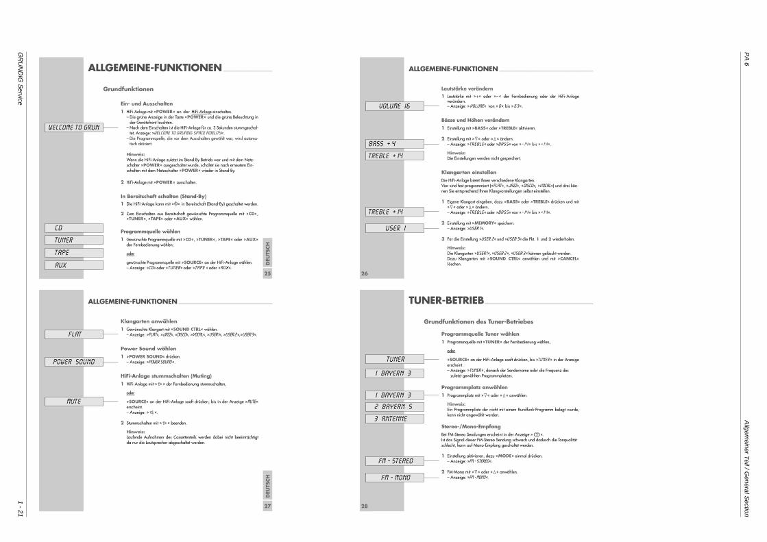
Ein- und Ausschalten1 HiFi-Anlage mit »POWER« an der HiFi-Anlage einschalten.
– Die grüne Anzeige in der Taste »POWER« und die grüne Beleuchtung inder Gerätefront leuchten.
– Nach dem Einschalten ist die HiFi-Anlage für ca. 3 Sekunden stummgeschal-tet, Anzeige: »WELCOME TO GRUNDIG SPACE FIDELITY«.
– Die Programmquelle, die vor dem Ausschalten gewählt war, wird automa-tisch aktiviert.
Hinweis:Wenn die HiFi-Anlage zuletzt im Stand-By Betrieb war und mit dem Netz-schalter »POWER« ausgeschaltet wurde, schaltet sie nach erneutem Ein-schalten mit dem Netzschalter »POWER« wieder in Stand-By.
2 HiFi-Anlage mit »POWER« ausschalten.
In Bereitschaft schalten (Stand-By)1 Die HiFi-Anlage kann mit »88« in Bereitschaft (Stand-By) geschaltet werden.
2 Zum Einschalten aus Bereitschaft gewünschte Programmquelle mit »CD«,»TUNER«, »TAPE« oder »AUX« wählen.
Programmquelle wählen1 Gewünschte Programmquelle mit »CD«, »TUNER«, »TAPE« oder »AUX«
der Fernbedienung wählen;
oder
gewünschte Programmquelle mit »SOURCE« an der HiFi-Anlage wählen.– Anzeige: »CD« oder »TUNER« oder »TAPE « oder »AUX «.
WELCOME TO GRUN
CD
TUNER
TAPE
AUX26
ALLGEMEINE-FUNKTIONEN ____________________________________________________
Lautstärke verändern1 Lautstärke mit »+« oder »–« der Fernbedienung oder der HiFi-Anlage
verändern.– Anzeige: » VOLUME« von » 0 « bis » 6 3 «.
Bässe und Höhen verändern1 Einstellung mit »BASS« oder »TREBLE« aktivieren.
2 Einstellung mit »1« oder »2« ändern.– Anzeige: »TREBLE« oder »BASS« von »- I 4 « bis »+ I 4 «.
Hinweis:Die Einstellungen werden nicht gespeichert.
Klangarten einstellenDie HiFi-Anlage bietet Ihnen verschiedene Klangarten.Vier sind fest programmiert (»FLAT«, »JAZZ«, »DISCO«, »VOCAL«) und drei kön-nen Sie entsprechend Ihren Klangvorstellungen selbst einstellen.
1 Eigene Klangart eingeben, dazu »BASS« oder »TREBLE« drücken und mit»1« oder »2« ändern.– Anzeige: »TREBLE« oder »BASS« von »- I 4 « bis »+ I 4 «.
2 Einstellung mit »MEMORY« speichern.– Anzeige: »USER 1«.
3 Für die Einstellung »USER 2« und »USER 3« die Pkt. 1 und 2 wiederholen.
Hinweis:Die Klangarten »USER I«, »USER 2 «, »USER 3 « können gelöscht werden.Dazu Klangarten mit »SOUND CTRL« anwählen und mit »CANCEL«löschen.
BASS + 4
TREBLE + I4
TREBLE + I4
USER 1
VOLUME 16
DEU
TSCH
27
ALLGEMEINE-FUNKTIONEN ____________________________________________________
Klangarten anwählen1 Gewünschte Klangart mit »SOUND CTRL« wählen.
– Anzeige: »FLAT«, »JAZZ«, »DISCO«, »VOCAL«, »USER I«, »USER 2 «,»USER 3 «.
Power Sound wählen1 »POWER SOUND« drücken.
– Anzeige: »POWER SOUND «.
HiFi-Anlage stummschalten (Muting) 1 HiFi-Anlage mit »s« der Fernbedienung stummschalten,
oder
»SOURCE« an der HiFi-Anlage sooft drücken, bis in der Anzeige »MUTE«erscheint.– Anzeige: »S«.
2 Stummschalten mit »s« beenden.
Hinweis: Laufende Aufnahmen des Cassettenteils werden dabei nicht beeinträchtigtda nur die Lautsprecher abgeschaltet werden.
POWER SOUND
MUTE
FLAT
28
TUNER-BETRIEB____________________________________________________________
Grundfunktionen des Tuner-Betriebes
Programmquelle Tuner wählen1 Programmquelle mit »TUNER« der Fernbedienung wählen,
oder
»SOURCE« an der HiFi-Anlage sooft drücken, bis »TUNER« in der Anzeigeerscheint.– Anzeige: »TUNER «, danach der Sendername oder die Frequenz des
zuletzt gewählten Programmplatzes.
Programmplatz anwählen1 Programmplatz mit »1« oder »2« anwählen.
Hinweis: Ein Programmplatz der nicht mit einem Rundfunk-Programm belegt wurde,kann nicht angewählt werden.
Stereo-/Mono-EmpfangBei FM-Stereo Sendungen erscheint in der Anzeige »!«.Ist das Signal dieser FM-Stereo Sendung schwach und dadurch die Tonqualitätschlecht, kann auf Mono-Empfang geschaltet werden.
1 Einstellung aktivieren, dazu »MODE« einmal drücken.– Anzeige: »FM - STEREO«.
2 FM-Mono mit »1« oder »2« anwählen.– Anzeige: »FM - MONO«.
TUNER
I BAYERN 3
FM - STEREO
FM - MONO
I BAYERN 3
3 ANTENNE
2 BAYERN 5
Allgem
einer Teil / G
eneral Section
PA
6
1 - 22G
RU
ND
IG S
ervice
DEU
TSCH
29
TUNER-BETRIEB__________________________________________________________________________
RDS-Empfang
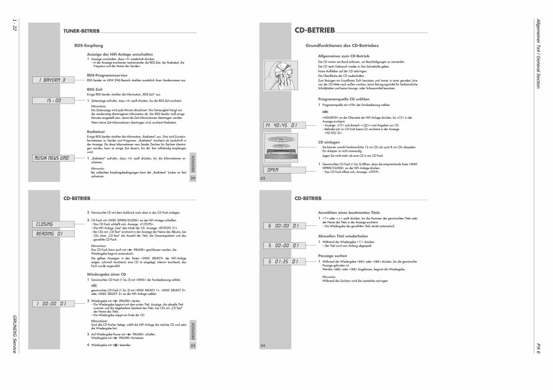
Anzeige der HiFi-Anlage umschalten1 Anzeige umschalten, dazu »i« wiederholt drücken.
– In der Anzeige erscheinen nacheinander die RDS-Zeit, der Radiotext, dieFrequenz und der Name des Senders.
RDS-ProgrammserviceRDS-Sender im UKW (FM)-Bereich strahlen zusätzlich ihren Sendernamen aus.
RDS-ZeitEinige RDS-Sender strahlen die Information „RDS-Zeit“ aus.
1 Zeitanzeige aufrufen, dazu »i« sooft drücken, bis die RDS-Zeit erscheint.
Hinweise:Die Zeitanzeige wird jede Minute aktualisiert. Die Genauigkeit hängt vonder senderseitig übertragenen Information ab. Der RDS-Sender muß einigeMinuten eingestellt sein, damit die Zeit-Informationen übertragen werden.
Wenn keine Zeit-Informationen übertragen wird, erscheint Radiotext.
RadiotextEinige RDS-Sender strahlen die Information „Radiotext“ aus. Dies sind Zusatzin-formationen zu Sender und Programm. „Radiotext“ erscheint als Laufschrift inder Anzeige. Da diese Informationen vom Sender Zeichen für Zeichen übertra-gen werden, kann es einige Zeit dauern, bis der Text vollständig empfangenwird.
1 „Radiotext“ aufrufen, dazu »i« sooft drücken, bis die Informationen er-scheinen.
Hinweis:Bei schlechten Empfangsbedingungen kann der „Radiotext“ Lücken im Textaufweisen.
15 : 00
I BAYERN 3
MUSIK NEWS UND
32
CD-BETRIEB_______________________________________________________________________
Grundfunktionen des CD-Betriebes
Allgemeines zum CD-BetriebDie CD immer am Rand anfassen, um Beschädigungen zu vermeiden.
Die CD nach Gebrauch wieder in ihre Schutzhülle geben.
Keine Aufkleber auf der CD anbringen.
Die Oberfläche der CD sauberhalten.
Zum Reinigen ein fusselfreies Tuch benutzen und immer in einer geraden Linievon der CD-Mitte nach außen wischen, keine Reinigungsmittel für herkömmlicheSchallplatten und keine Lösungs- oder Scheuermittel benutzen.
Programmquelle CD wählen1 Programmquelle mit »CD« der Fernbedienung wählen,
oder
»SOURCE« an der Oberseite der HiFi-Anlage drücken, bis »CD« in derAnzeige erscheint.– Anzeige: »CD« und danach »&« und Angaben zur CD.– Befindet sich im CD-Fach keine CD, erscheint in der Anzeige
»NO DISC DI«.
CD einlegenSie können sowohl herkömmliche 12 cm CDs als auch 8 cm CDs abspielen.Ein Adapter ist nicht notwendig.
Legen Sie nicht mehr als eine CD in ein CD-Fach.
1 Gewünschtes CD-Fach (1 bis 3) öffnen, dazu die entsprechende Taste »DISCOPEN/CLOSE« an der HiFi-Anlage drücken. – Das CD-Fach öffnet sich, Anzeige: »OPEN«.
14 40 :45 D I
OPEN
12 cm
8 cm
DEU
TSCH
33
CD-BETRIEB _________________________________________________________________________________
2 Gewünschte CD mit dem Aufdruck nach oben in das CD-Fach einlegen.
3 CD-Fach mit »DISC OPEN/CLOSE« an der HiFi-Anlage schließen.– Das CD-Fach schließt sich, Anzeige: »CLOSing«.– Die HiFi-Anlage „liest“ den Inhalt der CD, Anzeige: »READING DI«.– Bei CDs mit „CD-Text“ erscheint in der Anzeige der Name des Albums, bei
CDs ohne „CD-Text“ die Anzahl der Titel, die Gesamtspielzeit und dasgewählte CD-Fach.
Hinweise:Das CD-Fach kann auch mit »4 PAUSE« geschlossen werden, dieWiedergabe beginnt automatisch.
Die gelben Anzeigen in den Tasten »DISC SELECT« der HiFi-Anlagezeigen: schwach leuchtend, eine CD ist eingelegt; intensiv leuchtend, dasFach wurde angewählt.
Wiedergabe einer CD1 Gewünschtes CD-Fach (1 bis 3) mit »DISC« der Fernbedienung wählen
oder
gewünschtes CD-Fach (1 bis 3) mit »DISC SELECT 1«, »DISC SELECT 2«oder »DISC SELECT 3« an der HiFi-Anlage wählen.
2 Wiedergabe mit »4 PAUSE« starten.– Die Wiedergabe beginnt mit dem ersten Titel, Anzeige: die aktuelle Titel-
nummer und die abgelaufene Spielzeit des Titels, bei CDs mit „CD-Text“der Name des Titels.
– Die Wiedergabe stoppt am Ende der CD.
Hinweise: Sind alle CD-Fächer belegt, wählt die HiFi-Anlage die nächste CD und setztdie Wiedergabe fort.
3 Auf Wiedergabe-Pause mit »4 PAUSE« schalten. Wiedergabe mit »4 PAUSE« fortsetzen.
4 Wiedergabe mit »5« beenden.
closing
reading d 1
1 00 :00 D I
34
CD-BETRIEB _________________________________________________________________________________
Anwählen eines bestimmten Titels1 »1« oder »2« sooft drücken, bis die Nummer des gewünschten Titels oder
der Name des Titels in der Anzeige erscheint.– Die Wiedergabe des gewählten Titels startet automatisch.
Aktuellen Titel wiederholen1 Während der Wiedergabe »1« drücken.
– Der Titel wird vom Anfang abgespielt.
Passage suchen1 Während der Wiedergabe »9« oder »8« drücken, bis die gewünschte
Passage gefunden ist.Werden »9« oder »8« losgelassen, beginnt die Wiedergabe.
Hinweis:Während des Suchens wird die Lautstärke verringert.
6 00:00 D I
5 00 :00 D I
5 0 1 :35 D I

PA
6A
llgemeiner T
eil / General S
ection
GR
UN
DIG
Service
1 - 23
DEU
TSCH
35
CD-BETRIEB _________________________________________________________________________________
Besonderheiten im CD-Betrieb
Wiedergabe der Titel in zufälliger Reihenfolge (SHUFFLE)Bei dieser Funktion werden die Titel der CD in zufälliger Reihenfolge wiederge-geben.
1 Funktion anwählen, dazu »MODE« einmal drücken, die Anzeige »SHUFFLE OFF« erscheint.
2 Funktion »SHUFFLE ON« mit »1« oder »2« wählen.– Die Wiedergabe beginnt, die Titel aller eingelegten CDs oder des Musik-
programmes werden in zufälliger Reihenfolge abgespielt.
3 Zum Beenden der Funktion »5« drücken,
oder
CD-Fach mit »DISC OPEN/CLOSE« an der HiFi-Anlage öffnen.
Eine CD oder ein Musikprogramm wiederholen(Repeat)1 Funktion anwählen, dazu »MODE« zweimal drücken, die Anzeige
»REPEAT ON« oder »REPEAT OFF« erscheint.
2 Funktion »REPEAT ON« mit »1« oder »2« wählen.– Alle Titel der CDs, die sich in den CD-Fächern befinden oder das Musik-
programm werden wiederholt abgespielt. In der Anzeige der erscheint»J«.
3 Zum Beenden der Funktion die Einstellung wiederholen und die Anzeige»REPEAT OFF« wählen.
repeat ON
repeat OFF
shuffle ON
shuffle OFF
36
CD-BETRIEB _________________________________________________________________________________
Wiedergabe von Titeln in einer gewünschtenReihenfolge – Musikprogramm erstellen
Bei dieser Funktion können Sie bis zu 50 Titel der 3 CDs – die sich in den CD-Fächern befinden – in der von Ihnen gewünschten Reihenfolge speichern unddanach wiedergegeben.
Hinweis:Das Musikprogramm wird gelöscht, wenn das CD-Fach öffnen.
Titel auswählen und speichern
1 HiFi-Anlage mit »POWER« an der HiFi-Anlage einschalten.
2 CDs in die CD-Fächer einlegen.
3 Funktion mit »MEMORY« anwählen.
4 Gewünschten Titel mit »1« oder »2« anwählen und mit »MEMORY« speichern.– Anzeige: »2« die Anzahl der gespeicherten Titel, »5 P« der gewählte Titel, »D 1« das CD-Fach.
Hinweise:Weitere Titel speichern, dazu die Pkt.3 bis 4 wiederholen.
Wenn die Titel von mehreren CDs ausgewählt werden sollen, die jeweiligeCD mit »DISC« anwählen.
Nach dem 50 ten Titel erscheint in der Anzeige »MEM FULL«.
5 Einstellung mit »i« beenden.
0 1 D I
1 3 D I
2 5 p D I
MEM FULL
DEU
TSCH
37
Titelauswahl überprüfen
1 Zum Prüfen der gespeicherten Titel »MEMORY« 2 Sekunden drücken.
2 Titel mit »1« oder »2« anwählen.
Titelauswahl abspielen1 Wiedergabe der Titelauswahl mit »4 PAUSE« starten.
– Die Wiedergabe beginnt mit dem ersten Titel.
Titel aus dem Musikprogramm löschen1 Musikprogramm aufrufen, dazu »MEMORY« länger drücken.
2 Titel der gelöscht werden soll mit »1« oder »2« anwählen und mit »CANCEL« löschen.
Musikprogramm löschen1 Musikprogramm aufrufen, dazu »MEMORY« länger drücken.
– In der Anzeige erscheinen die gespeicherten Titel.
2 Zum Löschen des Musikprogramms »CANCEL« länger drücken.– Anzeige: »PRG ERASED«,
oder
CD-Fach öffnen.
CD-BETRIEB _________________________________________________________________________________
3 00:00 p
1 4 p D I
prg erased
40
CASSETTEN-BETRIEB________________________________________________
Allgemeines zum Cassetten-BetriebSchützen Sie Ihre Cassetten vor Feuchtigkeit, Staub, Hitze und Kälte.
Bewahren Sie Ihre Cassetten nicht in der Nähe starker Magnetfelder wie Fern-sehgeräte, Lautsprecherboxen usw. auf.
Geben Sie die Cassette nach Gebrauch wieder in die Schutzhülle.
Halten Sie bandführende Teile wie Andruckrolle, Tonwelle, Tonkopf oder Lösch-kopf frei von Bandabrieb, um gleichbleibend gute Aufnahme- und Wiedergabe-qualität zu erreichen. Reinigen Sie die Teile in regelmäßigen Abständen undverwenden Sie dazu spezielle Reinigungscassetten.
Programmquelle Cassette wählen1 Programmquelle mit »TAPE« der Fernbedienung wählen,
oder
»SOURCE« an der Oberseite der HiFi-Anlage drücken, bis »TAPE« in derAnzeige erscheint.– Befindet sich im Cassetten-Fach keine Cassette, erscheint in der Anzeige
»NO CASS«.
Cassette einlegenHinweis:Verwenden Sie für Wiedergabe Eisenoxid (I/Fe)-, Chromdioxid (II/Cr)- oderReineisen (IV/ME)-Cassetten. Die HiFi-Anlage paßt sich der verwendetenBandsorte automatisch an.Verwenden Sie für Aufnahmen nur Eisenoxid (I/Fe)- oder Chromdioxid(II/Cr)-Cassetten.
1 Cassetten-Fach öffnen, dazu »TAPE OPEN/CLOSE« an der HiFi-Anlage drücken.– Das Cassetten-Fach öffnet sich, Anzeige: »OPEN«.
NO CASS
OPEN
TAPE
Allgem
einer Teil / G
eneral Section
PA
6
1 - 24G
RU
ND
IG S
ervice
DEU
TSCH
41
CASSETTEN-BETRIEB__________________________________________________________________
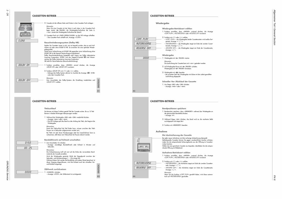
2 Cassette mit der offenen Seite nach hinten in das Cassetten-Fach einlegen.
Hinweis:Wenn Sie eine Cassette mit der Seite A nach oben in das Cassetten-Fachlegen startet »4 PAUSE« die Wiedergabe/Aufnahme der Seite A,»z t« startet die Wiedergabe/Aufnahme der Seite B.
3 Cassetten-Fach mit »TAPE OPEN/CLOSE« an der HiFi-Anlage schließen.– Das Cassetten-Fach schließt sich, Anzeige: »CLOSE«.
Rauschminderungssystem (Dolby NR)Spielen Sie Cassetten immer so ab, wie sie bespielt wurden, also je nach Auf-nahme mit oder ohne DOLBY B NR. So erreichen Sie eine optimale Wieder-gabequalität.Vorteil einer Aufzeichnung mit DOLBY NR gegenüber einer Aufzeichnung ohneDOLBY NR ist der bessere Geräuschspannungsabstand. Dolby Rauschunterdrückung hergestellt unter Lizenz von Dolby LaboratoriesLicensing Corporation. DOLBY und das Doppel-D-Symbol g sind Waren-zeichen der Dolby Laboratories Licensing Corporation.NR steht für Noise Reduction (Rauschunterdrückung).
1 Funktion anwählen, dazu »MODE« einmal drücken, die Anzeige »DOLBY ON« oder »DOLBY OFF« erscheint.
2 Funktion »DOLBY ON« mit »1« oder »2« wählen.– Solange das Dolby-System aktiviert ist, leuchtet die Anzeige »g B NR«
unter dem Cassetten-Fach.
Hinweis:Zum Ausschalten des Dolby-Systems die Einstellung wiederholen und»DOLBY OFF« wählen.
CLOSE
DOLBY ON
DOLBY OFF
A
42
CASSETTEN-BETRIEB__________________________________________________________________
Wiedergabe
Wiedergabe-Betriebsart wählen1 Funktion anwählen, dazu »MODE« zweimal drücken, die Anzeige
»CONT PLAY«, »AUTOREVERSE« oder »REVERSE OFF« erscheint.
2 Funktion mit »1« oder »2« wählen.– »CONT. PLAY« – die Wiedergabe beider Cassettenseiten wird endlos fort-
gesetzt, Anzeige: »J«.
– »AUTOREVERSE« – die Wiedergabe stoppt am Ende der zweiten Casset-tenseite, Anzeige: »H«.
– »REVERSE OFF« – die Wiedergabe stoppt am Ende der Cassettenseite,Anzeige: »G«.
Wiedergabe1 Wiedergabe mit »4 PAUSE« starten.
Hinweis:Die Laufrichtung der Cassette kann mit »z t« geändert werden.
2 Auf Wiedergabe-Pause mit »4 PAUSE« schalten. Wiedergabe mit »4 PAUSE« fortsetzen.
3 Wiedergabe mit »5« beenden.– Bei erneutem Start der Wiedergabe wird diese mit der zuletzt gewählten
Laufrichtung abgespielt.
Schneller Vor-/Rücklauf der Cassette1 Aus Stopp »9« oder »8« drücken.
– Anzeige: »W« oder »Q«.
autoreverse
reverse OFF
cont. play
0000
DEU
TSCH
43
CASSETTEN-BETRIEB__________________________________________________________________
TitelsuchlaufSie können mit dieser Funktion gezielt Titel der Cassette suchen. Bis zu 15 Titelkönnen in beiden Richtungen übersprungen werden.
1 Während der Wiedergabe »9« oder »8« wiederholt drücken.– Anzeige: »W« oder »Q«.– Die HiFi-Anlage spult das Band an den Anfang des Titels, dort beginnt die
Wiedergabe.
Hinweise:Damit der Titelsuchlauf die Titel finden kann, müssen zwischen den Titeln Pausen von 4 Sekunden aufgenommen worden sein.
Bei Titeln mit sehr leisen Musikpassagen oder bei Liveaufnahmen kann esvorkommen, daß diese vom Titelsuchlauf als Pausen erkannt werden.
Bandzählwerk auf Echtzeit umschalten1 Zum Umschalten »i« drücken.
– Anzeige: vierstelliges Bandzählwerk oder Echtzeit in Minuten undSekunden.
Hinweise:Die Echtzeitmessung muß sich erst auf die Dicke des verwendeten Band-materials der Cassette einstellen.
Wird die Wiedergabe gestartet, blinkt der Doppelpunkt zwischen derSekunden- und Minutenanzeige (- -:- -) für einige Zeit. Während dieser Zeit werden die Banddicke und andere Werte berechnet. Istdieser Vorgang abgeschlossen, wird die Echtzeit auch bei schnellem Vor-und Rücklauf angezeigt.
Zählwerk zurücksetzen1 »CANCEL« drücken.
– Anzeige: »0000«, der Zählerstand ist zurückgesetzt.
0 I50
00 : 25
0000
44
CASSETTEN-BETRIEB__________________________________________________________________
Bandpositionen speichern1 Bandposition speichern, dazu »MEMORY« während der Wiedergabe an
der gewünschten Bandstelle drücken.– Anzeige: »X«.
2 Während Stopp »8« drücken, das Band wird an die markierte Stellezurückgespult und stoppt dort.
3 Funktion mit »MEMORY« beenden.
Aufnahme
Die Löschsicherung der CassetteBei jeder neuen Aufnahme wird die vorherige Aufzeichnung überspielt.Selbstbespielte Cassetten können Sie gegen versehentliches Löschen schützen,indem Sie die entsprechende Sicherungslasche aus der Öffnung im Cassetten-rücken brechen.Wollen Sie eine gesicherte Cassette neu bespielen, überkleben Sie die entspre-chende Öffnung mit Klebeband.
Aufnahme-Betriebsart wählen1 Funktion anwählen, dazu »MODE« zweimal drücken, die Anzeige
»CONT PLAY«, »AUTOREVERSE« oder »REVERSE OFF« erscheint.
2 Funktion mit »1« oder »2« wählen.– »AUTOREVERSE« – die Aufnahme stoppt am Ende der zweiten Cassetten-
seite. Anzeige: »H«.
– »REVERSE OFF« – die Aufnahme stoppt am Ende der Cassettenseite.Anzeige: »G«.
Hinweis:Wenn Sie die Funktion »CONT PLAY« gewählt haben, wird diese automa-tisch auf »AUTOREVERSE« geschaltet.
autoreverse
reverse OFF
1
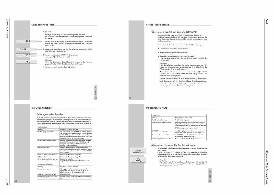
PA
6A
llgemeiner T
eil / General S
ection
GR
UN
DIG
Service
1 - 25
DEU
TSCH
45
CASSETTEN-BETRIEB__________________________________________________________________
AufnahmeWenn gewünscht, Dolby Rauschunterdrückungssystem aktivieren.Die Einstellung finden Sie im Kapitel „Rauschminderungssystem (Dolby NR)“auf Seite 41.
1 Cassette ohne Löschsicherung in das Cassetten-Fach legen, Cassettenlauf-richtung mit »z t« wählen und gewünschte Bandstelle mit »9« oder»8« suchen.
2 Gewünschte Signal-Quelle von der Sie aufnehmen möchten mit »CD«,»TUNER« oder »AUX« wählen.
3 Aufnahme starten, dazu »RECORD« länger drücken.– Anzeige: »)«, die Aufnahme startet.
Hinweis:Wenn Sie Cassetten mit Löschsicherung verwenden, ist die Aufnahmegesperrt, Anzeige »CASS«. Das Cassetten-Fach fährt heraus.
4 Aufnahme vorzeitig beenden, dazu »5« drücken.
1050
tuner
105 1
CASS
46
Überspielen von CD auf Cassette (CD COPY)Sie können das Überspielen von CD auf Cassette mit einer Taste startenSie können einzelne Titel einer CD oder eines Musikprogrammes so auf diebeiden Seiten einer Cassette verteilen, daß keine langen Leerpassagen am Endedes Bandes entstehen.
1 Cassette in das Cassetten-Fach und eine CD in das CD-Fach einlegen.
2 Cassette an die vorgesehene Bandstelle spulen.
3 Am CD-Spieler die gewünschten Titel wählen.
4 Überspielen starten, dazu »CD-COPY« länger drücken.– Die Aufnahme beginnt. Der CD-Spieler beginnt nach 4 Sekunden die
Wiedergabe.
Hinweise:Wird die Aufnahme am Anfang des Bandes begonnen, spielt die HiFi-Anlage ca. 6 Sekunden das Vorspannband ab. Anschließend wird dieWiedergabe der CD automatisch gestartet.
Während des Überspielens können nur die Tasten »5«, »DISCOPEN/CLOSE« oder »TAPE OPEN/CLOSE« betätigt werden. Alleanderen Funktionen sind gesperrt.
Wird die Wiedergabe der CD als erstes beendet, stoppt auch die Aufnahme.
Ist die Cassettenseite voll, wird die Wiedergabe der CD auf Pause geschaltet.
Ist der Reverse-Betrieb angewählt, wird die zweite Cassettenseite auto-matisch angewählt und die Aufnahme wird fortgesetzt.
CASSETTEN-BETRIEB__________________________________________________________________
48
INFORMATIONEN _____________________________________________________________________
Störungen selbst behebenNicht jede Tonstörung muß auf einen Defekt Ihrer HiFi-Anlage zurückführen. Auch verse-hentlich herausgezogene Anschlußkabel, beschädigte CDs, sowie verbrauchte Batteriender Fernbedienung, führen zu Funktionsstörungen. Wenn die folgenden Maßnahmen zukeinem befriedigenden Ergebnis führen, dann wenden Sie sich bitte an den Fachhandel!
ALLGEMEINES
Störung
Die HiFi-Anlage schaltet ab.
Die HiFi-Anlage funktioniert nicht.
Kein Ausgangssignal.
Linker und rechter Kanal vertauscht.
Baßtöne fehlen.
Die Fernbedienung funktioniert nicht.
RUNDFUNKEMPFANG
Störung
Kein Ausgangssignal.
Starkes Brummen oder Rauschen.
Das Empfangssignal ist zu schwach.
Mögliche Ursache/Abhilfe
Der Transformator kann überhitzt sein. Schalten Sie dieHifi-Anlage aus und entfernen Sie alle Objekte, die even-tuell die Belüftungsschlitze an der Rückseite des Gerätsbedecken. Lassen Sie die HiFi-Anlage für ca. 15 Minutenabkühlen, bevor Sie sie wieder einschalten.
Probleme durch elektrostatische Aufladungen. SchaltenSie die HiFi-Anlage mit der Taste POWER aus und wieder ein, oder ziehen Sie den Netzstecker undschließen ihn dann wieder an.
Erhöhen Sie die Lautstärke. Evtl. angeschlossenen Kopfhörer vom Gerät trennen. Anschluss der Klangröhreüberprüfen. Stellen Sie sicher, daß die Funktion MUTINGnicht aktiviert ist.
Anschluss der Klangröhre überprüfen.
Anschluss der Klangröhre überprüfen.
Batterien auswechseln.Zu großer Abstand oder falscher Winkel zum Gerät.
Mögliche Ursache/Abhilfe
Abhängig von schlechtem Stereoempfang, ist die Funktion MUTING aktiviert. Wählen Sie FM MONOoder korrigieren Sie die Frequenz manuell.
Antenne einstellen.
Schließen Sie eine Außenantenne für besseren Empfangan. D
EUTS
CH
49
INFORMATIONEN _____________________________________________________________________
Allgemeine Hinweise für Geräte mit LaserEin Schild nach nebenstehender Abbildung finden Sie an der GeräteunterseiteIhres Gerätes. CLASS 1 LASER PRODUCT bedeutet, daß der Laser wegen seines technischenAufbaus eigensicher ist, so daß der maximal erlaubte Ausstrahlwert unter kei-nen Umständen überschritten werden kann.
Vorsicht:Wenn andere als die hier spezifizierten Bedienungseinrichtungen benutztoder andere Verfahrensweisen ausgeführt werden, kann es zu gefährlicherStrahlungsexposition kommen.
CLASS 1LASER PRODUCT
CD-BETRIEB
Störung
Das CD-Fach schließt nicht.
Die Wiedergabe funktioniert nicht.
„NO DISC“ wird angezeigt.
Abspielen nicht vom ersten Titel an.
Die HiFi-Anlage funktioniert nicht
Mögliche Ursache/Abhilfe
CD nicht richtig eingelegt.
Schmutzige oder verkratzte CD oder die CD ist verkehrt eingelegt. Durch große Temperaturschwankungen hat sich Kondensfeuchtigkeit auf dem Linsensystem des Lasersgebildet. Sie trocknet nach einiger Zeit von selbst.
Keine CD eingelegt oder die CD ist verschmutzt, stark verkratzt oder wellig. Versuchen Sie eine andere CD.
Der PROGRAM - oder SHUFFLE-Modus ist aktiviert.5 und danach 4PAUSE drücken.
5 dann CANCEL, dann 4PAUSE drücken.

Allgem
einer Teil / G
eneral Section
PA
6
1 - 26G
RU
ND
IG S
ervice
Operating H
intsT
his chapter contains excerpts from the operating instructions. F
or further particulars please refer to the appropriate user instructions the part number
of which is indicated in the relevant spare parts list.
The HiFi system controls
Operating controls on the top side of the systemPOWER Switches the HiFi system on and off.
The HiFi is completely disconnected from thepower supply.The button contains a stand-by and modeindicator.
POWER Switches »POWER SOUND « (Loudness) on/off.SOUND
• Receiver for remote conrol signals.
Operating elements under the remote control
SOURCE Switches the HiFi on from Stand-by; Selects the input source and muting in thefollowing order: »CD «, »TUNER «, »TAPE «,»AUX «, »MUTE «, »CD «.
E Begins CD or cassette playback.
§§ Ends CD or cassette playback.
+ – Changes the volume within a range from »0« to»63 «.
POWER
POWERSOUND
SOURCE
ENG
LISH
7
OVERVIEW________________________________________________________________________ OVERVIEW__________________________________________________________________________________
8
Operating controls on the frontDISC Opens and closes the CD compartments.
OPEN/CLOSE
TAPE Opens and closes the tape compartment.OPEN/CLOSE
DISC SELECT Selects the CD in compartment 1, 2 1 2 3 or 3 for playback.
0 Headphone jack for connecting a stereoheadphone set with a jack plug (ø 6,3 mm).The loudspeakers of the HiFi system areautomatically switched off.
Display Stand-by and mode indicator.
DISCOPEN/CLOSE
TAPEOPEN/CLOSE
3
2
1
DISC SELECT
1 2 3
U
B NR
10
OVERVIEW__________________________________________________________________________________
The remote control
Buttons for general functions99 Switches the HiFi to Stand-by.
The green indicator in the button and the green light on thefront of the system are lit.
CD Switches the HiFi on from Stand-by mode and selects ”CD”operating mode.
TUNER Switches the HiFi on from Stand-by mode and selects”Tuner” operating mode.
TAPE Switches the HiFi on from Stand-by mode and selects the”Tape” operating mode.
AUX Switches the HiFi on from Stand-by mode and selects”AUX” operating mode.
MODE To activate the brightness setting function for the display,press this button three times, then press »1« or »2« toadjust the brightness.
Buttons for sound settingsPOWER Switches »POWER SOUND « (Loudness) on/off.SOUND
TREBLE Selects the Set treble function, then adjust with »1« »2«.
BASS Selects the Set bass function; then adjust with »1« »2«.
MEMORY Stores the ”USER” sound settings.
CANCEL Deletes the ”USER” sound settings.
+ – Changes the volume within a range of »0« to »63«.
a Switches the HiFi to and from mute mode.
SOUND Calls up various sound types.CONTROL
CD-COPY RECORD
MEMORY
CANCEL
SOUNDCTRL
MODE TREBLE
BASS
CD
TUNER
TAPE
AUX
DISCPOWERSOUND
PTY
PAUSE
8
111
ENG
LISH
11
OVERVIEW__________________________________________________________________________________
Tuner mode buttons
MEMORY Press this button and briefly hold it down to activatethe automatic station search (AUTO STORE).Stores radio stations for the AUTO TUNING andMANUAL TUNING functions.
8 9 Press briefly to change the frequency in incrementalsteps (MANUAL TUNING).
Press and then hold down briefly to initiate a manualstation search (AUTO TUNING).
1 2 Call up the next or previous preset station.
i Changes the display of the HiFi:Station name, RDS time, radio text (RDS stations only)and frequency.
CANCEL Press briefly to delete individual preset stations.
Hold down to delete all preset stations.
MODE Press once to select the FM stereo or FM mono settingfunction, then select the setting with »1« or »2«.
Press twice to select the Antenna setting function, thenselect the setting with 1« or »2«.
PTY Calls up the programme type code PTY,select the programme type with »1« or »2«.
CD-COPY RECORD
MEMORY
CANCEL
SOUNDCTRL
MODE TREBLE
BASS
CD
TUNER
TAPE
AUX
DISCPOWERSOUND
PTY
PAUSE
8
111
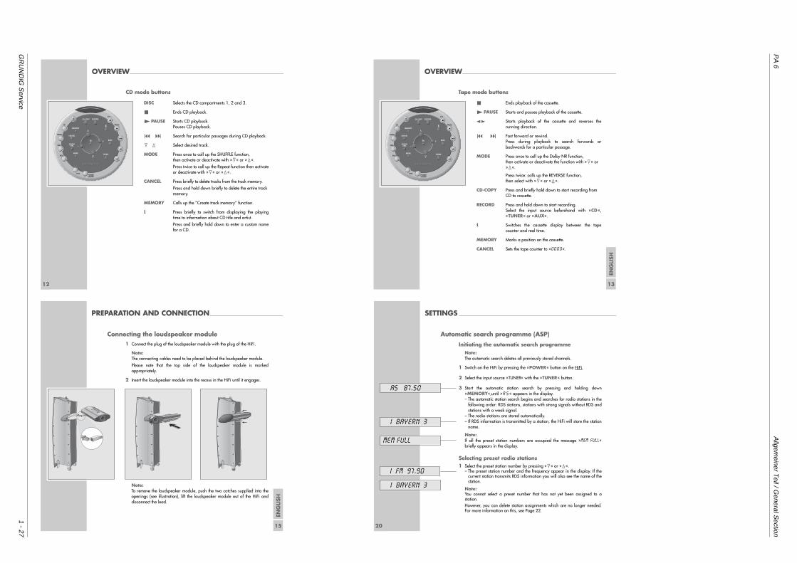
PA
6A
llgemeiner T
eil / General S
ection
GR
UN
DIG
Service
1 - 27
OVERVIEW__________________________________________________________________________________
12
CD mode buttons
DISC Selects the CD compartments 1, 2 and 3.
5 Ends CD playback.
4PAUSE Starts CD playback. Pauses CD playback.
8 9 Search for particular passages during CD playback.
1 2 Select desired track.
MODE Press once to call up the SHUFFLE function,then activate or deactivate with »1« or »2«.
Press twice to call up the Repeat function then activateor deactivate with »1« or »2«.
CANCEL Press briefly to delete tracks from the track memory.
Press and hold down briefly to delete the entire trackmemory.
MEMORY Calls up the ”Create track memory” function.
i Press briefly to switch from displaying the playingtime to information about CD title and artist.
Press and briefly hold down to enter a custom namefor a CD.
CD-COPY RECORD
MEMORY
CANCEL
SOUNDCTRL
MODE TREBLE
BASS
CD
TUNER
TAPE
AUX
DISCPOWERSOUND
PTY
PAUSE
8
111
OVERVIEW__________________________________________________________________________________
ENG
LISH
13
Tape mode buttons
5 Ends playback of the cassette.
4PAUSE Starts and pauses playback of the cassette.
z t Starts playback of the cassette and reverses therunning direction.
8 9 Fast forward or rewind.Press during playback to search forwards orbackwards for a particular passage.
MODE Press once to call up the Dolby NR function,then activate or deactivate the function with »1« or»2«.
Press twice: calls up the REVERSE function,then select with »1« or »2«.
CD-COPY Press and briefly hold down to start recording fromCD to cassette.
RECORD Press and hold down to start recording.Select the input source beforehand with »CD«,»TUNER« or »AUX«.
i Switches the cassette display between the tapecounter and real time.
MEMORY Marks a position on the cassette.
CANCEL Sets the tape counter to »0000«.
CD-COPY RECORD
MEMORY
CANCEL
SOUNDCTRL
MODE TREBLE
BASS
CD
TUNER
TAPE
AUX
DISCPOWERSOUND
PTY
PAUSE
8
111
ENG
LISH
15
PREPARATION AND CONNECTION_______________________________________
Connecting the loudspeaker module1 Connect the plug of the loudspeaker module with the plug of the HiFi.
Note: The connecting cables need to be placed behind the loudspeaker module.
Please note that the top side of the loudspeaker module is markedappropriately.
2 Insert the loudspeaker module into the recess in the HiFi until it engages.
Note:To remove the loudspeaker module, push the two catches supplied into theopenings (see illustration), lift the loudspeaker module out of the HiFi anddisconnect the lead.
TOP SIDE
OBEN
20
Automatic search programme (ASP)
Initiating the automatic search programmeNote:The automatic search deletes all previously stored channels.
1 Switch on the HiFi by pressing the »POWER« button on the HiFi.
2 Select the input source »TUNER« with the »TUNER« button.
3 Start the automatic station search by pressing and holding down»MEMORY«,until »A S« appears in the display.– The automatic station search begins and searches for radio stations in the
following order: RDS stations, stations with strong signals without RDS andstations with a weak signal.
– The radio stations are stored automatically.– If RDS information is transmitted by a station, the HiFi will store the station
name.
Note:If all the preset station numbers are occupied the message »MEM FULL«briefly appears in the display.
Selecting preset radio stations1 Select the preset station number by pressing »1« or »2«.
– The preset station number and the frequency appear in the display. If thecurrent station transmits RDS information you will also see the name of thestation.
Note:You cannot select a preset number that has not yet been assigned to astation.However, you can delete station assignments which are no longer needed.For more information on this, see Page 22.
SETTINGS ____________________________________________________________________________________
AS 87.50
MEM FULL
I FM 97.90
I BAYERN 3
I BAYERN 3
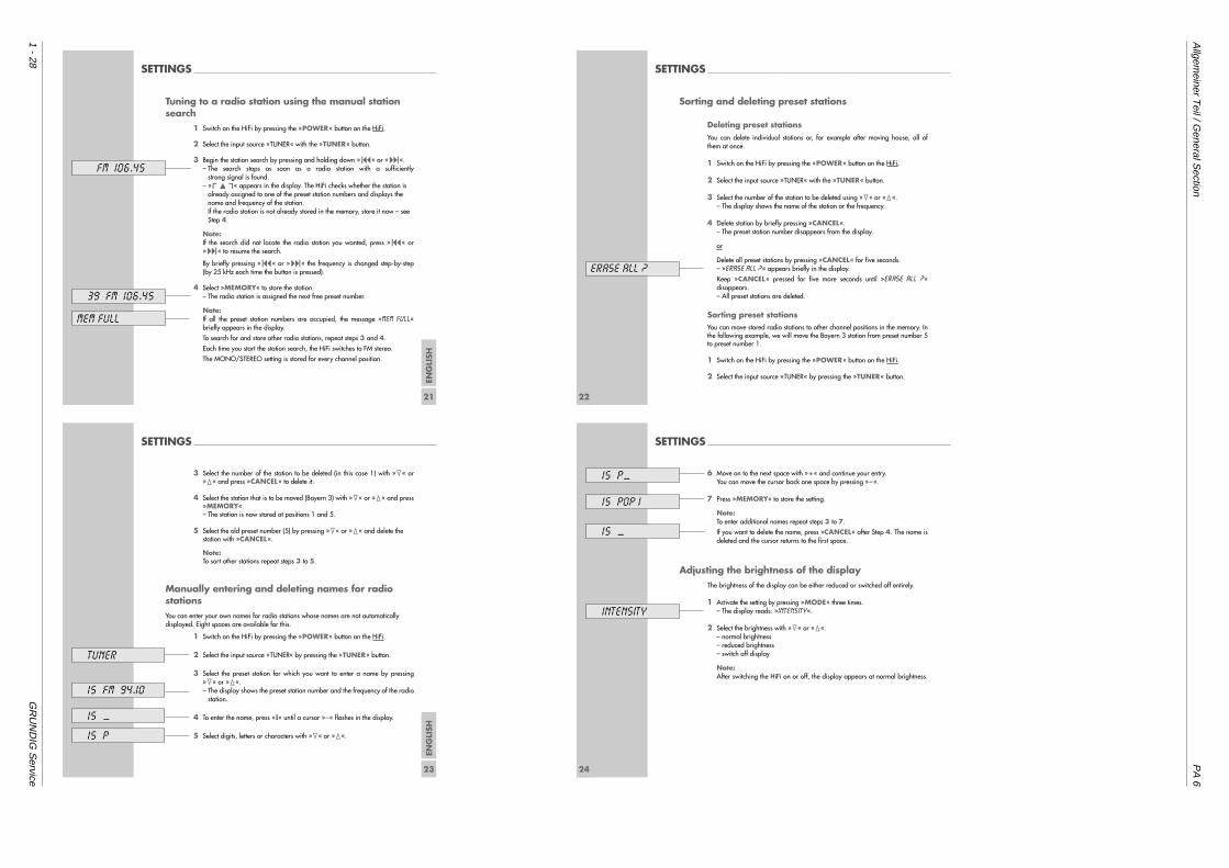
Allgem
einer Teil / G
eneral Section
PA
6
1 - 28G
RU
ND
IG S
ervice
SETTINGS ____________________________________________________________________________________
ENG
LISH
21
Tuning to a radio station using the manual stationsearch
1 Switch on the HiFi by pressing the »POWER« button on the HiFi.
2 Select the input source »TUNER« with the »TUNER« button.
3 Begin the station search by pressing and holding down »8« or »9«.– The search stops as soon as a radio station with a sufficiently
strong signal is found.– »%« appears in the display. The HiFi checks whether the station is
already assigned to one of the preset station numbers and displays thename and frequency of the station.If the radio station is not already stored in the memory, store it now – seeStep 4.
Note:If the search did not locate the radio station you wanted, press »8« or»9« to resume the search.
By briefly pressing »8« or »9« the frequency is changed step-by-step(by 25 kHz each time the button is pressed).
4 Select »MEMORY« to store the station.– The radio station is assigned the next free preset number.
Note:If all the preset station numbers are occupied, the message »MEM FULL«briefly appears in the display.
To search for and store other radio stations, repeat steps 3 and 4.
Each time you start the station search, the HiFi switches to FM stereo.
The MONO/STEREO setting is stored for every channel position.
MEM FULL
FM 106.45
39 FM 106.45
22
SETTINGS ____________________________________________________________________________________
Sorting and deleting preset stations
Deleting preset stationsYou can delete individual stations or, for example after moving house, all ofthem at once.
1 Switch on the HiFi by pressing the »POWER« button on the HiFi.
2 Select the input source »TUNER« with the »TUNER« button.
3 Select the number of the station to be deleted using »1« or »2«.– The display shows the name of the station or the frequency.
4 Delete station by briefly pressing »CANCEL«.– The preset station number disappears from the display.
or
Delete all preset stations by pressing »CANCEL« for five seconds.– »ERASE ALL ?« appears briefly in the display.
Keep »CANCEL« pressed for five more seconds until »ERASE ALL ?«disappears.– All preset stations are deleted.
Sorting preset stationsYou can move stored radio stations to other channel positions in the memory. Inthe following example, we will move the Bayern 3 station from preset number 5to preset number 1.
1 Switch on the HiFi by pressing the »POWER« button on the HiFi.
2 Select the input source »TUNER« by pressing the »TUNER« button.
ERASE ALL ?
ENG
LISH
23
SETTINGS ____________________________________________________________________________________
3 Select the number of the station to be deleted (in this case 1) with »1« or»2« and press »CANCEL« to delete it.
4 Select the station that is to be moved (Bayern 3) with »1« or »2« and press»MEMORY«.– The station is now stored at positions 1 and 5.
5 Select the old preset number (5) by pressing »1« or »2« and delete thestation with »CANCEL«.
Note:To sort other stations repeat steps 3 to 5.
Manually entering and deleting names for radiostationsYou can enter your own names for radio stations whose names are not automaticallydisplayed. Eight spaces are available for this.
1 Switch on the HiFi by pressing the »POWER« button on the HiFi.
2 Select the input source »TUNER« by pressing the »TUNER« button.
3 Select the preset station for which you want to enter a name by pressing»1« or »2«.– The display shows the preset station number and the frequency of the radio
station.
4 To enter the name, press »i« until a cursor »–« flashes in the display.
5 Select digits, letters or characters with »1« or »2«.
15 FM 94.10
TUNER
15 __
15 P
24
SETTINGS ____________________________________________________________________________________
6 Move on to the next space with »+« and continue your entry.You can move the cursor back one space by pressing »–«.
7 Press »MEMORY« to store the setting.
Note:To enter additional names repeat steps 3 to 7.
If you want to delete the name, press »CANCEL« after Step 4. The name isdeleted and the cursor returns to the first space.
Adjusting the brightness of the displayThe brightness of the display can be either reduced or switched off entirely.
1 Activate the setting by pressing »MODE« three times.– The display reads: »INTENSITY«.
2 Select the brightness with »1« or »2«.– normal brightness– reduced brightness– switch off display
Note:After switching the HiFi on or off, the display appears at normal brightness.
15 POP 1
15 __
INTENSITY
15 P__
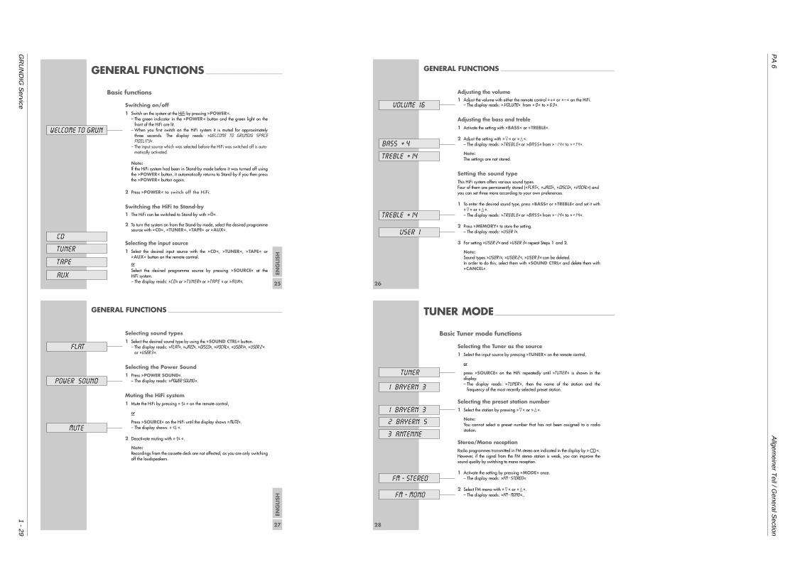
PA
6A
llgemeiner T
eil / General S
ection
GR
UN
DIG
Service
1 - 29
ENG
LISH
25
GENERAL FUNCTIONS _________________________________________
Basic functions
Switching on/off1 Switch on the system at the HiFi by pressing »POWER«.
– The green indicator in the »POWER« button and the green light on thefront of the HiFi are lit.
– When you first switch on the HiFi system it is muted for approximatelythree seconds. The display reads: »WELCOME TO GRUNDIG SPACEFIDELITY«.
– The input source which was selected before the HiFi was switched off is auto-matically activated.
Note:If the HiFi system had been in Stand-by mode before it was turned off usingthe »POWER« button, it automatically returns to Stand-by if you then pressthe »POWER« button again.
2 Press »POWER« to switch of f the HiFi.
Switching the HiFi to Stand-by1 The HiFi can be switched to Stand-by with »88«.
2 To turn the system on from the Stand-by mode, select the desired programmesource with »CD«, »TUNER«, »TAPE« or »AUX«.
Selecting the input source1 Select the desired input source with the »CD«, »TUNER«, »TAPE« or
»AUX« button on the remote control.
or
Select the desired programme source by pressing »SOURCE« at theHiFi system.– The display reads: »CD« or »TUNER« or »TAPE « or »AUX «.
WELCOME TO GRUN
CD
TUNER
TAPE
AUX26
GENERAL FUNCTIONS _____________________________________________________________
Adjusting the volume1 Adjust the volume with either the remote control »+« or »–« on the HiFi.
– The display reads: » VOLUME« from » 0 « to » 6 3 «.
Adjusting the bass and treble1 Activate the setting with »BASS« or »TREBLE«.
2 Adjust the setting with »1« or »2«.– The display reads: »TREBLE« or »BASS« from »- I 4 « to »+ I 4 «.
Note:The settings are not stored.
Setting the sound typeThis HiFi system offers various sound types.Four of them are permanently stored (»FLAT«, »JAZZ«, »DISCO«, »VOCAL«) andyou can set three more according to your own preferences.
1 To enter the desired sound type, press »BASS« or »TREBLE« and set it with»1« or »2«.– The display reads: »TREBLE« or »BASS« from »- I 4 « to »+ I 4 «.
2 Press »MEMORY« to store the setting.– The display reads: »USER 1«.
3 For setting »USER 2« and »USER 3« repeat Steps 1 and 2.
Note:Sound types »USER I«, »USER 2 «, »USER 3 « can be deleted.In order to do this, select them with »SOUND CTRL« and delete them with»CANCEL«.
BASS + 4
TREBLE + I4
TREBLE + I4
USER 1
VOLUME 16
ENG
LISH
27
GENERAL FUNCTIONS _____________________________________________________________
Selecting sound types1 Select the desired sound type by using the »SOUND CTRL« button.
– The display reads: »FLAT«, »JAZZ«, »DISCO«, »VOCAL«, »USER I«, »USER 2 «or »USER 3 «.
Selecting the Power Sound1 Press »POWER SOUND«.
– The display reads: »POWER SOUND «.
Muting the HiFi system1 Mute the HiFi by pressing »s« on the remote control,
or
Press »SOURCE« on the HiFi until the display shows »MUTE«.– The display shows: »S«.
2 Deactivate muting with »s«.
Note: Recordings from the cassette deck are not affected, as you are only switchingoff the loudspeakers.
POWER SOUND
MUTE
FLAT
28
TUNER MODE ________________________________________________________________
Basic Tuner mode functions
Selecting the Tuner as the source1 Select the input source by pressing »TUNER« on the remote control,
or
press »SOURCE« on the HiFi repeatedly until »TUNER« is shown in thedisplay.– The display reads: »TUNER «, then the name of the station and the
frequency of the most recently selected preset station.
Selecting the preset station number1 Select the station by pressing »1« or »2«.
Note: You cannot select a preset number that has not been assigned to a radiostation.
Stereo/Mono receptionRadio programmes transmitted in FM stereo are indicated in the display by »!«.However, if the signal from the FM stereo station is weak, you can improve thesound quality by switching to mono reception.
1 Activate the setting by pressing »MODE« once.– The display reads: »FM - STEREO«.
2 Select FM mono with »1« or »2«.– The display reads: »FM - MONO«.‚
TUNER
I BAYERN 3
FM - STEREO
FM - MONO
I BAYERN 3
3 ANTENNE
2 BAYERN 5
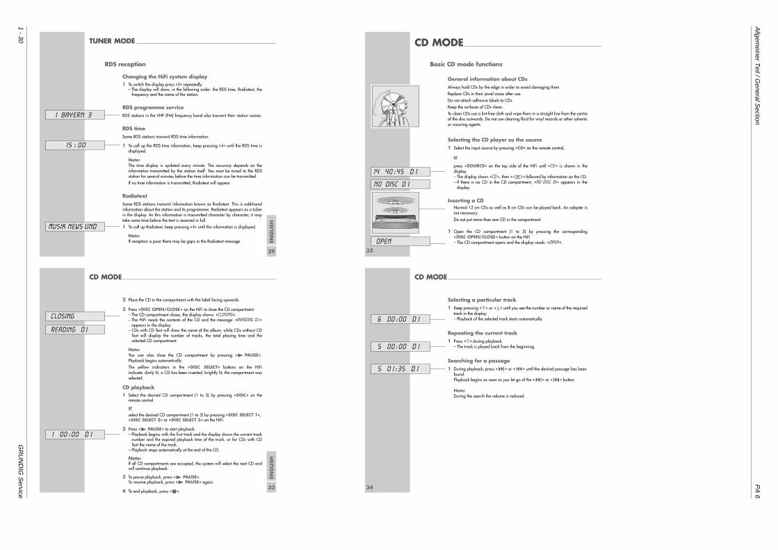
Allgem
einer Teil / G
eneral Section
PA
6
1 - 30G
RU
ND
IG S
ervice
ENG
LISH
29
TUNER MODE_____________________________________________________________________________
RDS reception
Changing the HiFi system display1 To switch the display press »i« repeatedly.
– The display will show, in the following order: the RDS time, Radiotext, thefrequency and the name of the station.
RDS programme serviceRDS stations in the VHF (FM) frequency band also transmit their station names.
RDS timeSome RDS stations transmit RDS time information.
1 To call up the RDS time information, keep pressing »i« until the RDS time isdisplayed.
Note:The time display is updated every minute. The accuracy depends on theinformation transmitted by the station itself. You must be tuned to the RDSstation for several minutes before the time information can be transmitted.
If no time information is transmitted, Radiotext will appear.
RadiotextSome RDS stations transmit information known as Radiotext. This is additionalinformation about the station and its programmes. Radiotext appears as a tickerin the display. As this information is transmitted character by character, it maytake some time before the text is received in full.
1 To call up Radiotext, keep pressing »i« until the information is displayed.
Note:If reception is poor there may be gaps in the Radiotext message.
15 : 00
I BAYERN 3
MUSIK NEWS UND
32
CD MODE___________________________________________________________________________
Basic CD mode functions
General information about CDsAlways hold CDs by the edge in order to avoid damaging them.
Replace CDs in their jewel cases after use.
Do not attach adhesive labels to CDs.
Keep the surfaces of CDs clean.
To clean CDs use a lint-free cloth and wipe them in a straight line from the centreof the disc outwards. Do not use cleaning fluid for vinyl records or other solventsor scouring agents.
Selecting the CD player as the source1 Select the input source by pressing »CD« on the remote control,
or
press »SOURCE« on the top side of the HiFi until »CD« is shown in thedisplay.– The display shows »CD«, then »&« followed by information on the CD.– If there is no CD in the CD compartment, »NO DISC DI« appears in the
display.
Inserting a CDNormal 12 cm CDs as well as 8 cm CDs can be played back. An adapter isnot necessary.
Do not put more than one CD in the compartment.
1 Open the CD compartment (1 to 3) by pressing the corresponding»DISC OPEN/CLOSE« button on the HiFi.– The CD compartment opens and the display reads: »OPEN«.
14 40 :45 D I
NO DISC D I
OPEN
12 cm
8 cm
ENG
LISH
33
CD MODE____________________________________________________________________________________
2 Place the CD in the compartment with the label facing upwards.
3 Press »DISC OPEN/CLOSE« on the HiFi to close the CD compartment.– The CD compartment closes, the display shows: »CLOSing«.– The HiFi reads the contents of the CD and the message: »READING DI«
appears in the display.– CDs with CD Text will show the name of the album, while CDs without CD
Text will display the number of tracks, the total playing time and theselected CD compartment.
Note:You can also close the CD compartment by pressing »4 PAUSE«.Playback begins automatically.
The yellow indicators in the »DISC SELECT« buttons on the HiFi indicate: dimly lit, a CD has been inserted; brightly lit, the compartment wasselected.
CD playback1 Select the desired CD compartment (1 to 3) by pressing »DISC« on the
remote control
or
select the desired CD compartment (1 to 3) by pressing »DISC SELECT 1«,»DISC SELECT 2« or »DISC SELECT 3« on the HiFi.
2 Press »4 PAUSE« to start playback.– Playback begins with the first track and the display shows the current track
number and the expired playback time of the track, or for CDs with CDText the name of the track.
– Playback stops automatically at the end of the CD.
Note:If all CD compartments are occupied, the system will select the next CD andwill continue playback.
3 To pause playback, press »4 PAUSE«.To resume playback, press »4 PAUSE« again.
4 To end playback, press »5«.
closing
reading d 1
1 00 :00 D I
34
CD MODE____________________________________________________________________________________
Selecting a particular track1 Keep pressing »1« or »2« until you see the number or name of the required
track in the display.– Playback of the selected track starts automatically.
Repeating the current track1 Press »1« during playback.
– The track is played back from the beginning.
Searching for a passage1 During playback, press »9« or »8« until the desired passage has been
found.Playback begins as soon as you let go of the »9« or »8« button.
Note:During the search the volume is reduced.
6 00:00 D I
5 00 :00 D I
5 0 1 :35 D I
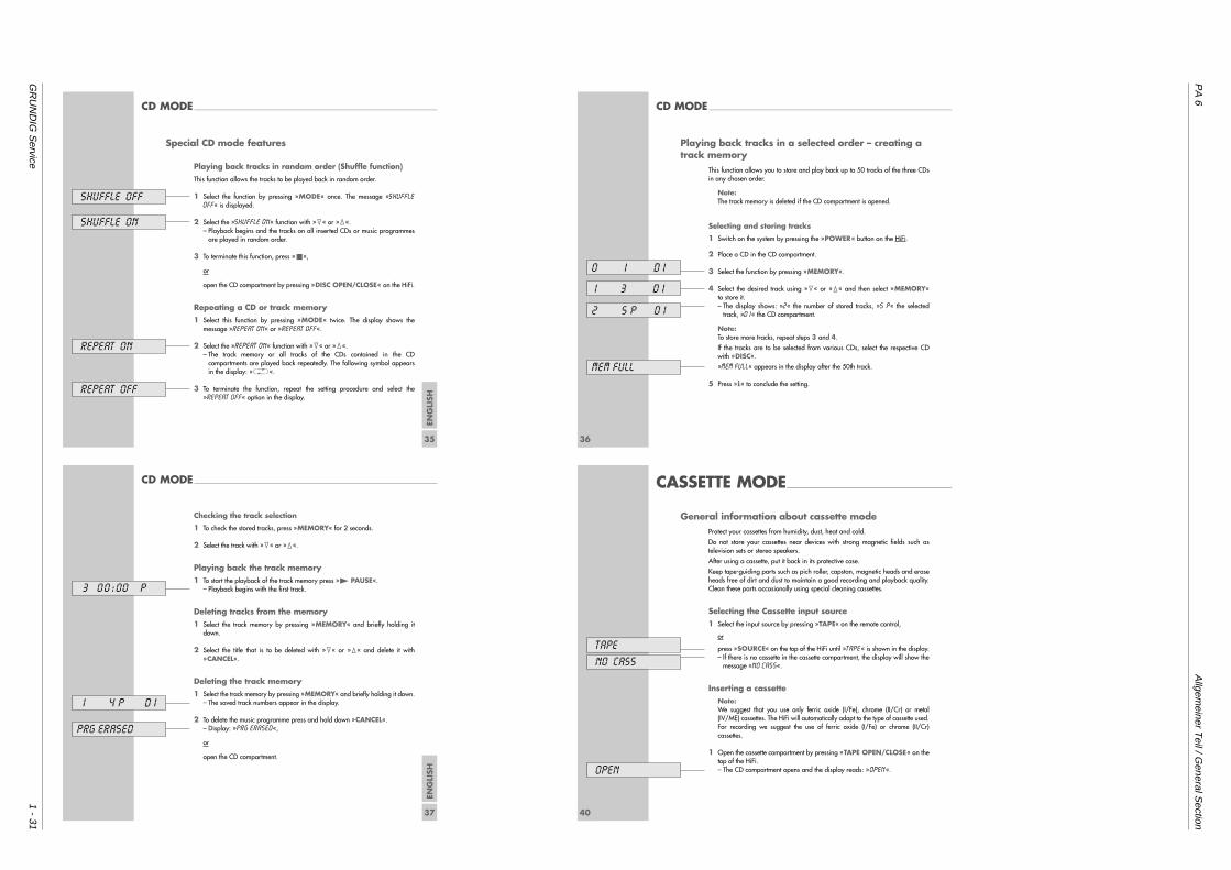
PA
6A
llgemeiner T
eil / General S
ection
GR
UN
DIG
Service
1 - 31
ENG
LISH
35
CD MODE____________________________________________________________________________________
Special CD mode features
Playing back tracks in random order (Shuffle function)This function allows the tracks to be played back in random order.
1 Select the function by pressing »MODE« once. The message »SHUFFLEOFF« is displayed.
2 Select the »SHUFFLE ON« function with »1« or »2«.– Playback begins and the tracks on all inserted CDs or music programmes
are played in random order.
3 To terminate this function, press »5«,
or
open the CD compartment by pressing »DISC OPEN/CLOSE« on the HiFi.
Repeating a CD or track memory1 Select this function by pressing »MODE« twice. The display shows the
message »REPEAT ON« or »REPEAT OFF«.
2 Select the »REPEAT ON« function with »1« or »2«.– The track memory or all tracks of the CDs contained in the CD
compartments are played back repeatedly. The following symbol appearsin the display: »J«.
3 To terminate the function, repeat the setting procedure and select the»REPEAT OFF« option in the display.
repeat ON
repeat OFF
shuffle ON
shuffle OFF
36
CD MODE____________________________________________________________________________________
Playing back tracks in a selected order – creating atrack memory
This function allows you to store and play back up to 50 tracks of the three CDsin any chosen order.
Note:The track memory is deleted if the CD compartment is opened.
Selecting and storing tracks
1 Switch on the system by pressing the »POWER« button on the HiFi.
2 Place a CD in the CD compartment.
3 Select the function by pressing »MEMORY«.
4 Select the desired track using »1« or »2« and then select »MEMORY« to store it.– The display shows: »2« the number of stored tracks, »5 P« the selected
track, »D 1« the CD compartment.
Note:To store more tracks, repeat steps 3 and 4.
If the tracks are to be selected from various CDs, select the respective CDwith »DISC«.
»MEM FULL« appears in the display after the 50th track.
5 Press »i« to conclude the setting.
0 1 D I
1 3 D I
2 5 p D I
MEM FULL
ENG
LISH
37
Checking the track selection
1 To check the stored tracks, press »MEMORY« for 2 seconds.
2 Select the track with »1« or »2«.
Playing back the track memory1 To start the playback of the track memory press »4 PAUSE«.
– Playback begins with the first track.
Deleting tracks from the memory1 Select the track memory by pressing »MEMORY« and briefly holding it
down.
2 Select the title that is to be deleted with »1« or »2« and delete it with»CANCEL«.
Deleting the track memory1 Select the track memory by pressing »MEMORY« and briefly holding it down.
– The saved track numbers appear in the display.
2 To delete the music programme press and hold down »CANCEL«.– Display: »PRG ERASED«,
or
open the CD compartment.
CD MODE____________________________________________________________________________________
3 00:00 p
1 4 p D I
prg erased
40
CASSETTE MODE_________________________________________________________
General information about cassette modeProtect your cassettes from humidity, dust, heat and cold.
Do not store your cassettes near devices with strong magnetic fields such astelevision sets or stereo speakers.
After using a cassette, put it back in its protective case.
Keep tape-guiding parts such as pich roller, capstan, magnetic heads and eraseheads free of dirt and dust to maintain a good recording and playback quality.Clean these parts occasionally using special cleaning cassettes.
Selecting the Cassette input source1 Select the input source by pressing »TAPE« on the remote control,
or
press »SOURCE« on the top of the HiFi until »TAPE« is shown in the display.– If there is no cassette in the cassette compartment, the display will show the
message »NO CASS«.
Inserting a cassetteNote:We suggest that you use only ferric oxide (I/Fe), chrome (II/Cr) or metal(IV/ME) cassettes. The HiFi will automatically adapt to the type of cassette used.For recording we suggest the use of ferric oxide (I/Fe) or chrome (II/Cr)cassettes.
1 Open the cassette compartment by pressing »TAPE OPEN/CLOSE« on thetop of the HiFi.– The CD compartment opens and the display reads: »OPEN«.
NO CASS
OPEN
TAPE
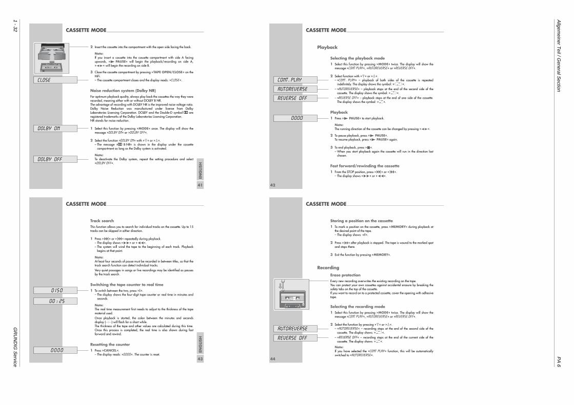
Allgem
einer Teil / G
eneral Section
PA
6
1 - 32G
RU
ND
IG S
ervice
ENG
LISH
41
CASSETTE MODE________________________________________________________________________
2 Insert the cassette into the compartment with the open side facing the back.
Note:If you insert a cassette into the cassette compartment with side A facingupwards, »4 PAUSE« will begin the playback/recording on side A,»z t« will begin the recording on side B.
3 Close the cassette compartment by pressing »TAPE OPEN/CLOSE« on theHiFi.– The cassette compartment closes and the display reads: »CLOSE«.
Noise reduction system (Dolby NR)For optimum playback quality, always play back the cassettes the way they wererecorded, meaning either with or without DOLBY B NR.The advantage of recording with DOLBY NR is the improved noise voltage ratio. Dolby Noise Reduction was manufactured under license from DolbyLaboratories Licensing Corporation. DOLBY and the Double-D symbol g areregistered trademarks of the Dolby Laboratories Licensing Corporation.NR stands for noise reduction.
1 Select this function by pressing »MODE« once. The display will show themessage »DOLBY ON« or »DOLBY OFF«.
2 Select the function »DOLBY ON« with »1« or »2«.– The message »g B NR« is shown in the display under the cassette
compartment as long as the Dolby system is activated.
Note:To deactivate the Dolby system, repeat the setting procedure and select»DOLBY OFF«.
CLOSE
DOLBY ON
DOLBY OFF
A
42
CASSETTE MODE________________________________________________________________________
Playback
Selecting the playback mode1 Select this function by pressing »MODE« twice. The display will show the
message »CONT PLAY«, »AUTOREVERSE« or »REVERSE OFF«.
2 Select function with »1« or »2«.– »CONT. PLAY« – playback of both sides of the cassette is repeated
indefinitely. The display shows the symbol: »J«.
– »AUTOREVERSE« – playback stops at the end of the second side of thecassette. The display shows the symbol: »H«.
– »REVERSE OFF« – playback stops at the end of one side of the cassette.The display shows the symbol: »G«.
Playback1 Press »4 PAUSE« to start playback.
Note:The running direction of the cassette can be changed by pressing »z t«.
2 To pause playback, press »4 PAUSE«. To resume playback, press »4 PAUSE« again.
3 To end playback, press »5«.– When you start playback again the cassette will run in the direction last
chosen.
Fast forward/rewinding the cassette1 From the STOP position, press »9« or »8«.
– The display shows »W« or »Q«.
autoreverse
reverse OFF
cont. play
0000
ENG
LISH
43
CASSETTE MODE________________________________________________________________________
Track searchThis function allows you to search for individual tracks on the cassette. Up to 15tracks can be skipped in either direction.
1 Press »9« or »8« repeatedly during playback.– The display shows »W« or »Q«.– The system will wind the tape to the beginning of each track. Playback
begins at that point.
Note:At least four seconds of pause must be recorded in between titles, so that thetrack search function can detect individual tracks.
Very quiet passages in songs or live recordings may be identified as pausesby the track search.
Switching the tape counter to real time1 To switch between the two, press »i«.
– The display shows the four-digit tape counter or real time in minutes andseconds.
Note:The real time measurement first needs to adjust to the thickness of the tapematerial used.
Once playback is started, the colon between the minutes and secondsdisplay (- -:- -) will flash for a short while.The thickness of the tape and other values are calculated during this time.Once this process is completed, the real time is also shown during fastforward and rewind.
Resetting the counter1 Press »CANCEL«.
– The display reads: »0000«. The counter is reset.
0 I50
00 : 25
0000
44
CASSETTE MODE________________________________________________________________________
Storing a position on the cassette1 To mark a position on the cassette, press »MEMORY« during playback at
the desired point of the tape.– The display shows: »X«.
2 Press »8« after playback is stopped. The tape is wound to the marked spotand stops there.
3 Exit the function by pressing »MEMORY«.
Recording
Erase protectionEvery new recording overwrites the existing recording on the tape.You can protect your own cassettes against accidental erasure by breaking thesafety tabs on the top of the cassette.If you want to record on to a protected cassette, cover the opening with adhesivetape.
Selecting the recording mode1 Select this function by pressing »MODE« twice. The display will show the
message »CONT PLAY«, »AUTOREVERSE« or »REVERSE OFF«.
2 Select the function by pressing »1« or »2«.– »AUTOREVERSE« – recording stops at the end of the second side of the
cassette. The display shows: »H«.
– »REVERSE OFF« – recording stops at the end of the current side of thecassette. The display shows: »G«.
Note:If you have selected the »CONT PLAY« function, this will be automaticallyswitched to »AUTOREVERSE«.
autoreverse
reverse OFF
1
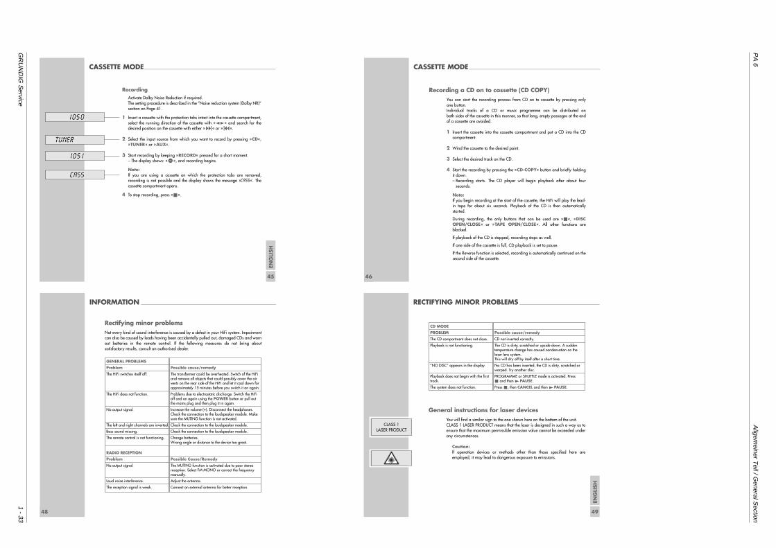
PA
6A
llgemeiner T
eil / General S
ection
GR
UN
DIG
Service
1 - 33
ENG
LISH
45
CASSETTE MODE________________________________________________________________________
RecordingActivate Dolby Noise Reduction if required.The setting procedure is described in the ”Noise reduction system (Dolby NR)”section on Page 41.
1 Insert a cassette with the protection tabs intact into the cassette compartment,select the running direction of the cassette with »z t« and search for thedesired position on the cassette with either »9« or »8«.
2 Select the input source from which you want to record by pressing »CD«,»TUNER« or »AUX«.
3 Start recording by keeping »RECORD« pressed for a short moment.– The display shows: »)«, and recording begins.
Note:If you are using a cassette on which the protection tabs are removed,recording is not possible and the display shows the message »CASS«. Thecassette compartment opens.
4 To stop recording, press »5«.
1050
tuner
105 1
CASS
46
Recording a CD on to cassette (CD COPY)You can start the recording process from CD on to cassette by pressing only one button.Individual tracks of a CD or music programme can be distributed onboth sides of the cassette in this manner, so that long, empty passages at the endof a cassette are avoided.
1 Insert the cassette into the cassette compartment and put a CD into the CDcompartment.
2 Wind the cassette to the desired point.
3 Select the desired track on the CD.
4 Start the recording by pressing the »CD-COPY« button and briefly holdingit down.– Recording starts. The CD player will begin playback after about four
seconds.
Note:If you begin recording at the start of the cassette, the HiFi will play the lead-in tape for about six seconds. Playback of the CD is then automaticallystarted.
During recording, the only buttons that can be used are »5«, »DISCOPEN/CLOSE« or »TAPE OPEN/CLOSE«. All other functions areblocked.
If playback of the CD is stopped, recording stops as well.
If one side of the cassette is full, CD playback is set to pause.
If the Reverse function is selected, recording is automatically continued on thesecond side of the cassette.
CASSETTE MODE________________________________________________________________________
48
INFORMATION __________________________________________________________________________
Rectifying minor problemsNot every kind of sound interference is caused by a defect in your HiFi system. Impairmentcan also be caused by leads having been accidentally pulled out, damaged CDs and wornout batteries in the remote control. If the following measures do not bring aboutsatisfactory results, consult an authorised dealer.
GENERAL PROBLEMS
Problem
The HiFi switches itself off.
The HiFi does not function.
No output signal.
The left and right channels are inverted.
Bass sound missing.
The remote control is not functioning.
RADIO RECEPTION
Problem
No output signal.
Loud noise interference.
The reception signal is weak.
Possible cause/remedy
The transformer could be overheated. Switch of the HiFiand remove all objects that could possibly cover the airvents on the rear side of the HiFi and let it cool down forapproximately 15 minutes before you switch it on again.
Problems due to electrostatic discharge. Switch the HiFioff and on again using the POWER button or pull outthe mains plug and then plug it in again.
Increase the volume (+). Disconnect the headphones.Check the connection to the loudspeaker module. Makesure the MUTING function is not activated.
Check the connection to the loudspeaker module.
Check the connection to the loudspeaker module.
Change batteries.Wrong angle or distance to the device too great.
Possible Cause/Remedy
The MUTING function is activated due to poor stereoreception. Select FM MONO or correct the frequencymanually.
Adjust the antenna.
Connect an external antenna for better reception.
ENG
LISH
49
RECTIFYING MINOR PROBLEMS ____________________________________________
General instructions for laser devicesYou will find a similar sign to the one shown here on the bottom of the unit. CLASS 1 LASER PRODUCT means that the laser is designed in such a way as toensure that the maximum permissible emission value cannot be exceeded underany circumstances.
Caution:If operation devices or methods other than those specified here areemployed, it may lead to dangerous exposure to emissions.
CLASS 1LASER PRODUCT
CD MODE
PROBLEM
The CD compartment does not close.
Playback is not functioning.
”NO DISC” appears in the display.
Playback does not begin with the firsttrack.
The system does not function.
Possible cause/remedy
CD not inserted correctly.
The CD is dirty, scratched or upside down. A suddentemperature change has caused condensation on thelaser lens system.This will dry off by itself after a short time.
No CD has been inserted, the CD is dirty, scratched orwarped. Try another disc.
PROGRAMME or SHUFFLE mode is activated. Press 5 and then 4PAUSE.
Press 5, then CANCEL and then 4PAUSE.
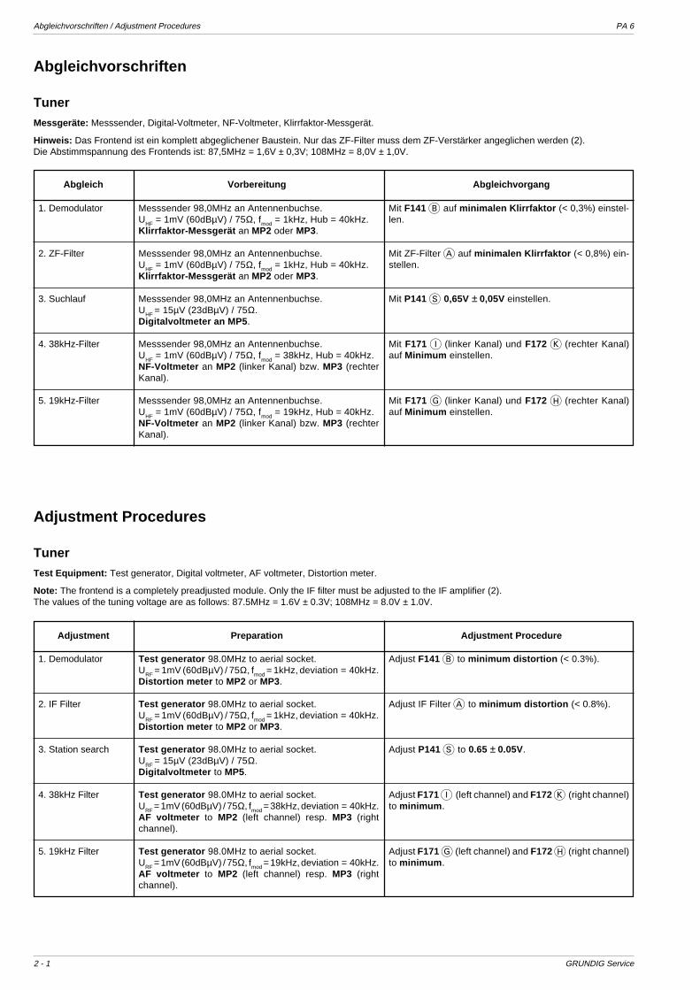
Abgleichvorschriften / Adjustment Procedures PA 6
2 - 1 GRUNDIG Service
Abgleichvorschriften
TunerMessgeräte: Messsender, Digital-Voltmeter, NF-Voltmeter, Klirrfaktor-Messgerät.
Hinweis: Das Frontend ist ein komplett abgeglichener Baustein. Nur das ZF-Filter muss dem ZF-Verstärker angeglichen werden (2).Die Abstimmspannung des Frontends ist: 87,5MHz = 1,6V ± 0,3V; 108MHz = 8,0V ± 1,0V.
Abgleich Vorbereitung Abgleichvorgang
Mit F141 B auf minimalen Klirrfaktor (< 0,3%) einstel-len.
Mit ZF-Filter A auf minimalen Klirrfaktor (< 0,8%) ein-stellen.
Mit P141 S 0,65V ± 0,05V einstellen.
Mit F171 I (linker Kanal) und F172 K (rechter Kanal)auf Minimum einstellen.
Mit F171 G (linker Kanal) und F172 H (rechter Kanal)auf Minimum einstellen.
1. Demodulator
2. ZF-Filter
3. Suchlauf
4. 38kHz-Filter
5. 19kHz-Filter
Messsender 98,0MHz an Antennenbuchse.UHF = 1mV (60dBµV) / 75Ω, fmod = 1kHz, Hub = 40kHz.Klirrfaktor-Messgerät an MP2 oder MP3.
Messsender 98,0MHz an Antennenbuchse.UHF = 1mV (60dBµV) / 75Ω, fmod = 1kHz, Hub = 40kHz.Klirrfaktor-Messgerät an MP2 oder MP3.
Messsender 98,0MHz an Antennenbuchse.UHF = 15µV (23dBµV) / 75Ω.Digitalvoltmeter an MP5 .
Messsender 98,0MHz an Antennenbuchse.U
HF = 1mV (60dBµV) / 75Ω, f
mod = 38kHz, Hub = 40kHz.
NF-Voltmeter an MP2 (linker Kanal) bzw. MP3 (rechterKanal).
Messsender 98,0MHz an Antennenbuchse.UHF = 1mV (60dBµV) / 75Ω, fmod = 19kHz, Hub = 40kHz.NF-Voltmeter an MP2 (linker Kanal) bzw. MP3 (rechterKanal).
Adjustment Procedures
TunerTest Equipment: Test generator, Digital voltmeter, AF voltmeter, Distortion meter.
Note: The frontend is a completely preadjusted module. Only the IF filter must be adjusted to the IF amplifier (2).The values of the tuning voltage are as follows: 87.5MHz = 1.6V ± 0.3V; 108MHz = 8.0V ± 1.0V.
Adjustment Preparation Adjustment Procedure
Test generator 98.0MHz to aerial socket.URF = 1mV (60dBµV) / 75Ω, fmod = 1kHz, deviation = 40kHz.Distortion meter to MP2 or MP3.
Test generator 98.0MHz to aerial socket.URF = 1mV (60dBµV) / 75Ω, fmod = 1kHz, deviation = 40kHz.Distortion meter to MP2 or MP3.
Test generator 98.0MHz to aerial socket.URF = 15µV (23dBµV) / 75Ω.Digitalvoltmeter to MP5.
Test generator 98.0MHz to aerial socket.URF = 1mV (60dBµV) / 75Ω, fmod = 38kHz, deviation = 40kHz.AF voltmeter to MP2 (left channel) resp. MP3 (rightchannel).
Test generator 98.0MHz to aerial socket.URF = 1mV (60dBµV) / 75Ω, fmod = 19kHz, deviation = 40kHz.AF voltmeter to MP2 (left channel) resp. MP3 (rightchannel).
Adjust F141 B to minimum distortion (< 0.3%).
Adjust IF Filter A to minimum distortion (< 0.8%).
Adjust P141 S to 0.65 ± 0.05V.
Adjust F171 I (left channel) and F172 K (right channel)to minimum .
Adjust F171 G (left channel) and F172 H (right channel)to minimum .
1. Demodulator
2. IF Filter
3. Station search
4. 38kHz Filter
5. 19kHz Filter
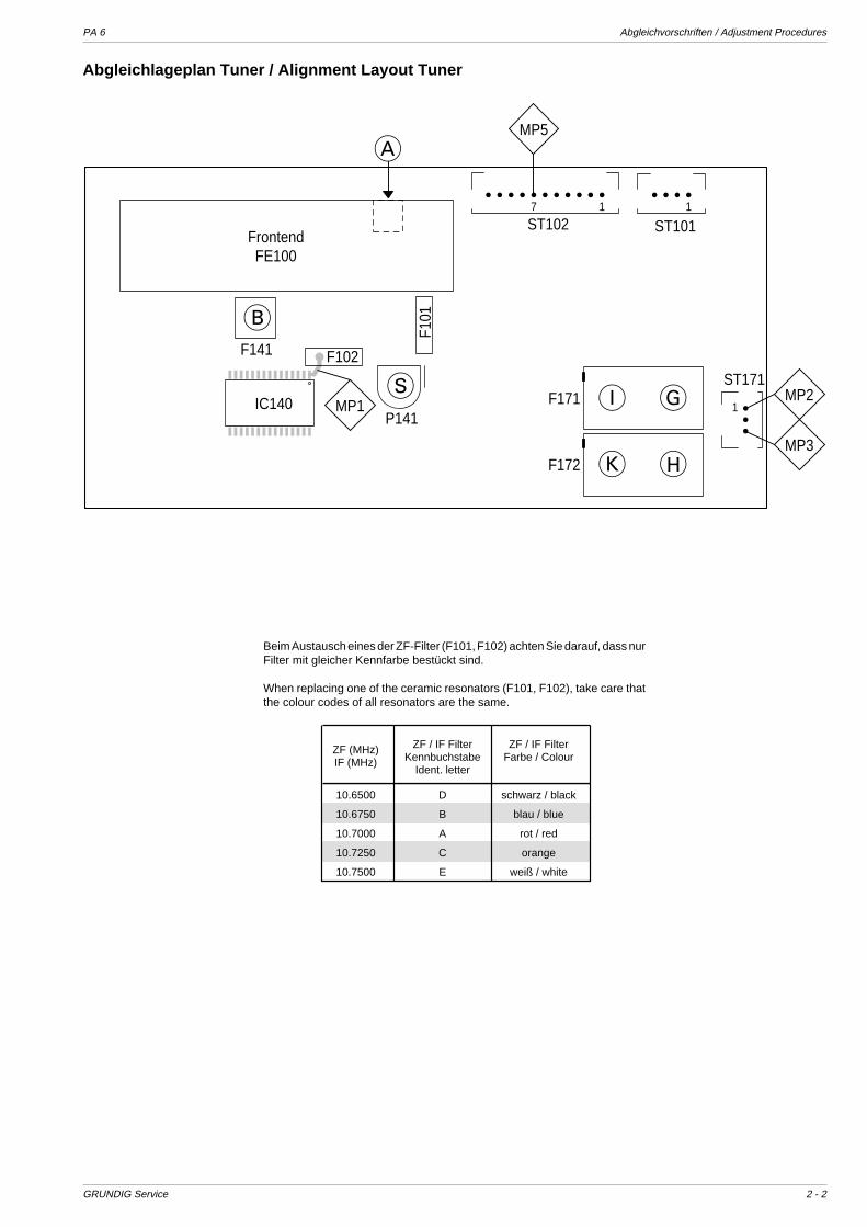
PA 6 Abgleichvorschriften / Adjustment Procedures
GRUNDIG Service 2 - 2
F171
F141
FrontendFE100
F172
P141
ST171
1
117
ST101ST102
F101
F102
IC140
A
B
S I G
K H
MP2
MP3
MP1
MP5
Abgleichlageplan Tuner / Alignment Layout Tuner
Beim Austausch eines der ZF-Filter (F101, F102) achten Sie darauf, dass nurFilter mit gleicher Kennfarbe bestückt sind.
When replacing one of the ceramic resonators (F101, F102), take care thatthe colour codes of all resonators are the same.
ZF (MHz)IF (MHz)
ZF / IF FilterKennbuchstabe
Ident. letter
ZF / IF FilterFarbe / Colour
10.6500 D schwarz / black
10.6750 B blau / blue
10.7000 A rot / red
10.7250 C orange
10.7500 E weiß / white
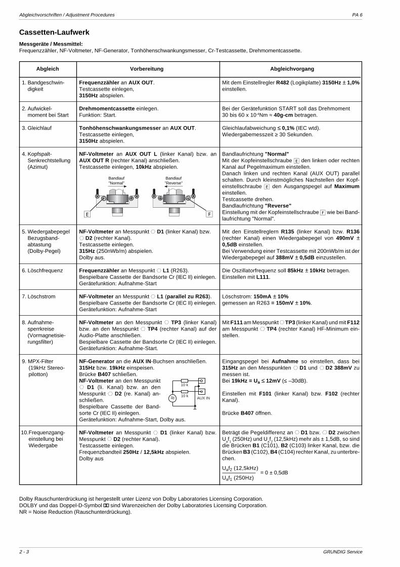
Abgleichvorschriften / Adjustment Procedures PA 6
2 - 3 GRUNDIG Service
Mit dem Einstellregler R482 (Logikplatte) 3150Hz ± 1,0%einstellen.
Bei der Gerätefunktion START soll das Drehmoment30 bis 60 x 10-4Nm ≈ 40g-cm betragen.
Gleichlaufabweichung ≤ 0,1% (IEC wtd).Wiedergabemesszeit ≥ 30 Sekunden.
Bandlaufrichtung "Normal"Mit der Kopfeinstellschraube E den linken oder rechtenKanal auf Pegelmaximum einstellen.Danach linken und rechten Kanal (AUX OUT) parallelschalten. Durch kleinstmögliches Nachstellen der Kopf-einstellschraube E den Ausgangspegel auf Maximumeinstellen.Testcassette drehen.Bandlaufrichtung "Reverse"Einstellung mit der Kopfeinstellschraube F wie bei Band-laufrichtung "Normal".
Mit den Einstellreglern R135 (linker Kanal) bzw. R136(rechter Kanal) einen Wiedergabepegel von 490mV ±0,5dB einstellen.Bei Verwendung einer Testcassette mit 200nWb/m ist derWiedergabepegel auf 388mV ± 0,5dB einzustellen.
Die Oszillatorfrequenz soll 85kHz ± 10kHz betragen.Einstellen mit L111.
Löschstrom: 150mA ± 10%gemessen an R263 = 150mV ± 10%.
Mit F111 am Messpunkt TP3 (linker Kanal) und mit F112am Messpunkt TP4 (rechter Kanal) HF-Minimum ein-stellen.
Eingangspegel bei Aufnahme so einstellen, dass bei315Hz an den Messpunkten D1 und D2 388mV zumessen ist.Bei 19kHz = Ua ≤ 12mV (≤ –30dB).
Einstellen mit F101 (linker Kanal) bzw. F102 (rechterKanal).
Brücke B407 öffnen.
Beträgt die Pegeldifferenz an D1 bzw. D2 zwischenU
af1 (250Hz) und U
af2 (12,5kHz) mehr als ± 1,5dB, so sind
die Brücken B1 (C101), B2 (C103) linker Kanal, bzw. dieBrücken B3 (C102), B4 (C104) rechter Kanal, zu unterbre-chen.
Uaf2 (12,5kHz)
Uaf1 (250Hz)
1. Bandgeschwin-digkeit
2. Aufwickel-moment bei Start
3. Gleichlauf
4. Kopfspalt-Senkrechtstellung(Azimut)
5. WiedergabepegelBezugsband-abtastung(Dolby-Pegel)
6. Löschfrequenz
7. Löschstrom
8. Aufnahme-sperrkreise(Vormagnetisie-rungsfilter)
9. MPX-Filter(19kHz Stereo-pilotton)
10.Frequenzgang-einstellung beiWiedergabe
Abgleich Vorbereitung Abgleichvorgang
Frequenzzähler an AUX OUT.Testcassette einlegen,3150Hz abspielen.
Drehmomentcassette einlegen.Funktion: Start.
Tonhöhenschwankungsmesser an AUX OUT.Testcassette einlegen,3150Hz abspielen.
NF-Voltmeter an AUX OUT L (linker Kanal) bzw. anAUX OUT R (rechter Kanal) anschließen.Testcassette einlegen, 10kHz abspielen.
NF-Voltmeter an Messpunkt D1 (linker Kanal) bzw. D2 (rechter Kanal).
Testcassette einlegen.315Hz (250nWb/m) abspielen.Dolby aus.
Frequenzzähler an Messpunkt L1 (R263).Bespielbare Cassette der Bandsorte Cr (IEC II) einlegen.Gerätefunktion: Aufnahme-Start
NF-Voltmeter an Messpunkt L1 (parallel zu R263 ).Bespielbare Cassette der Bandsorte Cr (IEC II) einlegen.Gerätefunktion: Aufnahme-Start
NF-Voltmeter an den Messpunkt TP3 (linker Kanal)bzw. an den Messpunkt TP4 (rechter Kanal) auf derAudio-Platte anschließen.Bespielbare Cassette der Bandsorte Cr (IEC II) einlegen.Gerätefunktion: Aufnahme-Start.
NF-Generator an die AUX IN-Buchsen anschließen.315Hz bzw. 19kHz einspeisen.Brücke B407 schließen.NF-Voltmeter an den Messpunkt
D1 (li. Kanal) bzw. an denMesspunkt D2 (re. Kanal) an-schließen.Bespielbare Cassette der Band-sorte Cr (IEC II) einlegen.Gerätefunktion: Aufnahme-Start, Dolby aus.
NF-Voltmeter an Messpunkt D1 (linker Kanal) bzw.Messpunkt D2 (rechter Kanal).Testcassette einlegen.Frequenzbandteil 250Hz / 12,5kHz abspielen.Dolby aus
Cassetten-Laufwerk
Messgeräte / Messmittel:Frequenzzähler, NF-Voltmeter, NF-Generator, Tonhöhenschwankungsmesser, Cr-Testcassette, Drehmomentcassette.
FE
Bandlauf"Reverse"
Bandlauf"Normal"
≈
10 k
10 kAUX IN
= 0 ± 0,5dB
Dolby Rauschunterdrückung ist hergestellt unter Lizenz von Dolby Laboratories Licensing Corporation.DOLBY und das Doppel-D-Symbol g sind Warenzeichen der Dolby Laboratories Licensing Corporation.NR = Noise Reduction (Rauschunterdrückung).
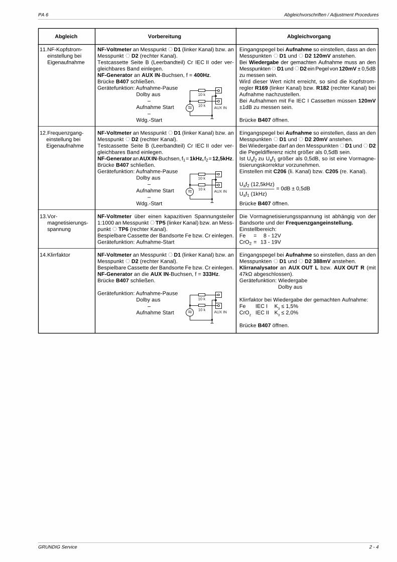
PA 6 Abgleichvorschriften / Adjustment Procedures
GRUNDIG Service 2 - 4
Abgleich Vorbereitung Abgleichvorgang
11.NF-Kopfstrom-einstellung beiEigenaufnahme
12.Frequenzgang-einstellung beiEigenaufnahme
13.Vor-magnetisierungs-spannung
14.Klirrfaktor
NF-Voltmeter an Messpunkt D1 (linker Kanal) bzw. anMesspunkt D2 (rechter Kanal).Testcassette Seite B (Leerbandteil) Cr IEC II oder ver-gleichbares Band einlegen.NF-Generator an AUX IN-Buchsen, f = 400Hz.Brücke B407 schließen.Gerätefunktion: Aufnahme-Pause
Dolby aus–
Aufnahme Start–
Wdg.-Start
NF-Voltmeter an Messpunkt D1 (linker Kanal) bzw. anMesspunkt D2 (rechter Kanal).Testcassette Seite B (Leerbandteil) Cr IEC II oder ver-gleichbares Band einlegen.NF-Generator an AUX IN-Buchsen, f1 = 1kHz, f2 = 12,5kHz.Brücke B407 schließen.Gerätefunktion: Aufnahme-Pause
Dolby aus–
Aufnahme Start–
Wdg.-Start
NF-Voltmeter über einen kapazitiven Spannungsteiler1:1000 an Messpunkt TP5 (linker Kanal) bzw. an Mess-punkt TP6 (rechter Kanal).Bespielbare Cassette der Bandsorte Fe bzw. Cr einlegen.Gerätefunktion: Aufnahme-Start
NF-Voltmeter an Messpunkt D1 (linker Kanal) bzw. anMesspunkt D2 (rechter Kanal).Bespielbare Cassette der Bandsorte Fe bzw. Cr einlegen.NF-Generator an die AUX IN-Buchsen, f = 333Hz.Brücke B407 schließen.
Gerätefunktion: Aufnahme-PauseDolby aus
–Aufnahme Start
Eingangspegel bei Aufnahme so einstellen, dass an denMesspunkten D1 und D2 120mV anstehen.Bei Wiedergabe der gemachten Aufnahme muss an denMesspunkten D1 und D2 ein Pegel von 120mV ± 0,5dBzu messen sein.Wird dieser Wert nicht erreicht, so sind die Kopfstrom-regler R169 (linker Kanal) bzw. R182 (rechter Kanal) beiAufnahme nachzustellen.Bei Aufnahmen mit Fe IEC I Cassetten müssen 120mV±1dB zu messen sein.
Brücke B407 öffnen.
Eingangspegel bei Aufnahme so einstellen, dass an denMesspunkten D1 und D2 20mV anstehen.Bei Wiedergabe darf an den Messpunkten D1 und D2die Pegeldifferenz nicht größer als 0,5dB sein.Ist Uaf2 zu Uaf1 größer als 0,5dB, so ist eine Vormagne-tisierungskorrektur vorzunehmen.Einstellen mit C206 (li. Kanal) bzw. C205 (re. Kanal).
Uaf2 (12,5kHz)
Uaf1 (1kHz)
Brücke B407 öffnen.
Die Vormagnetisierungsspannung ist abhängig von derBandsorte und der Frequenzgangeinstellung.Einstellbereich:Fe = 8 - 12VCrO2 = 13 - 19V
Eingangspegel bei Aufnahme so einstellen, dass an denMesspunkten D1 und D2 388mV anstehen.Klirranalysator an AUX OUT L bzw. AUX OUT R (mit47kΩ abgeschlossen).Gerätefunktion: Wiedergabe
Dolby aus
Klirrfaktor bei Wiedergabe der gemachten Aufnahme:Fe IEC I K3 ≤ 1,5%CrO2 IEC II K3 ≤ 2,0%
Brücke B407 öffnen.
= 0dB ± 0,5dB
≈
10 k
10 kAUX IN
≈
10 k
10 kAUX IN
≈
10 k
10 kAUX IN
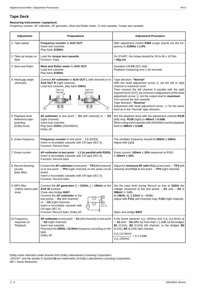
Abgleichvorschriften / Adjustment Procedures PA 6
2 - 5 GRUNDIG Service
Tape Deck
Measuring instruments / equipment:Frequency counter, AF voltmeter, AF generator, Wow and flutter meter, Cr test cassette, Torque test cassette.
With adjustment control R482 (Logic board) set the fre-quency to 3150Hz ± 1.0%.
On START, the torque should be 30 to 60 x 10-4Nm≈ 40g-cm .
Deviation ≤ 0.1% (IEC wtd).Playback measuring time ≥ 30 seconds.
Tape direction: "Normal"With the head adjustment screw E set the left or rightchannel to maximum level.Then connect the left channel in parallel with the rightchannel (AUX OUT). By minimum readjustment of the headadjustment screw E set the output level to maximum .Turn around the test cassette.Tape direction: "Reverse "Adjustment with head adjustment screw F for the samelevel as in the "Normal" tape direction.
Set the playback level with the adjustment controls R135(left) resp. R136 (right) to 490mV ± 0.5dB.When using a test cassette with 200nWb/m set the playbacklevel to 388mV ± 0.5dB .
The oscillator frequency should be 85kHz ± 10kHz.Adjust with L111.
Erase current: 150mA ± 10% measured at R263= 150mV ± 10%.
Adjust for minimum RF with F111 at test point TP3 (leftchannel) and F112 at test point TP4 (right channel).
Set the input level during Record so that at 315Hz thevoltage measured at the test points D1 and D2 is388mV (= 0dB).At 19kHz: Uo ≤ 12mV (≤ –30dB).Adjust with F101 (left channel) resp. F102 (right channel).
Open wire bridge B407.
If the levels between Vof1 (250Hz) and Vof2 (12.5kHz) atD1 and D2 differ by more than + 1.5dB cut the bridges
B1 (C101), B2 (C103) left channel, or the bridges B3(C102), B4 (C104) right channel.
Vof2 (12.5kHz)
Vof1 (250Hz)
Adjustment Preparations Adjustment Procedure
Frequency counter to AUX OUT.Insert test cassette.Play back 3150Hz.
Load the torque test cassette .Function: Start.
Wow and flutter meter to AUX OUT.Load test cassette.Play back 3150Hz.
Connect AF-voltmeter to AUX OUT L (left channel) or toAUX OUT R (right channel).Load test cassette, play back 10kHz.
AF-voltmeter to test point D1 (left channel) or D2(right channel).Insert test cassette.Play back 315Hz (250nWb/m).Dolby off.
Frequency counter to test point L1 (R263).Insert a recordable cassette with CR tape (IEC II).Function: Record-Start.
AF-voltmeter to test point L1 (in parallel with R263).Insert a recordable cassette with CR tape (IEC II).Function: Record-Start.
Connect the AF-voltmeter to test point TP3 (left channel)or to test point TP4 (right channel) on the audio circuitboard.Insert a recordable cassette with CR tape (IEC II).Function: Record-Start.
Connect the AF-generator (f1 = 315Hz, f2 = 19kHz) to theAUX IN sockets.Close wire bridge B407.Connect the AF-voltmeter to thetest points D1 (left channel)or D2 (right channel).Insert a recordable cassette withCR tape (IEC II).Function: Record-Start, Dolby off.
AF-voltmeter to test point D1 (left channel) or test point D2 (right channel).
Insert test cassette.Play back the 250Hz / 12.5kHz frequency recording on thetape.Dolby off
FE
Tape run"Reverse"
Tape run"Normal"
1. Tape speed
2. Take-up torque onStart
3. Wow and flutter
4. Head gap angle(Azimuth)
5. Playback levelReference tapescanning(Dolby level)
6. Erase frequency
7. Erase current
8. Record blockingcircuits(bias filter)
9. MPX-filter(19kHz stereo pilottone)
10.Frequencyresponse onPlayback
≈
10 k
10 kAUX IN
= 0 ± 0.5dB
Dolby noise reduction under license from Dolby Laboratories Licensing Corporation.„DOLBY“ and the double D Symbol g are trademarks of Dolby Laboratories Licensing Corporation.NR = Noise Reduction.

PA 6 Abgleichvorschriften / Adjustment Procedures
GRUNDIG Service 2 - 6
Adjustment Preparations Adjustment Procedure
Set the input level during Record so that the voltagemeasured at the test points D1 and D2 is 120mV.On playing back the recording made on the cassetterecorder, a voltage level of 120mV ± 0.5dB must bepresent at the test points D1 and D2.If the level differs from the value above re-adjust the headcurrent control R169 (left channel) resp. R182 (right chan-nel) during recording.When recording on Fe IEC I cassettes the voltage must be120mV ± 1dB.
Open wire bridge B407.
Set the input level during Record so that the voltagemeasured at the test points D1 and D2 is 20mV.When playing back the recording the levels at the testpoints D1 and D2 must not differ by more than 0.5dB.If Vof2 to Vof1 is higher than 0.5dB correct the bias.Re-adjust with C206 left channel, resp. C205 right chan-nel.
Vof2 (12.5kHz)
Vof1 (1kHz)
Open wire bridge B407.
The bias voltage depends on the type of tape and thefrequency response setting .Adjustment range:Fe = 8 - 12VCrO2 = 13 - 19V
Set the input level during Record so that the voltagemeasured at the test points D1 and D2 is 388mV.Distortion analyzer to AUX OUT L or AUX OUT R sockets(47kΩ termination).Function: Playback
Dolby offDistortion factor measured on playing back the recordingmade:Fe IEC I K3 ≤ 1.5%CrO2 IEC II K3 ≤ 2.0%
Open wire bridge B407.
AF-voltmeter to test point D1 (left channel) or test point D2 (right channel).
Insert test cassette, side B (blank part), Cr IEC II or similartape.AF-generator to AUX IN sockets, f = 400Hz.Close wire bridge B407.Function: Record-Pause
Dolby off–
Record-Start–
Playback-Start
AF-voltmeter to test point D1 (left channel) or test point D2 (right channel).
Insert test cassette, side B (blank part) Cr IEC II or similartape.AF-generator to AUX IN sockets, f1 = 1kHz, f2 = 12.5kHz.Close wire bridge B407.Function: Record-Pause
Dolby off–
Record-Start–
Playback-Start
AF-voltmeter with a 1:1000 capacitive voltage divider totest point TP5 (left channel) or TP6 (right channel).Insert a recordable cassette, Fe or Cr tape.Function: Record-Start
AF-voltmeter to test point D1 (left channel) or test point D2 (right channel).
Insert a recordable cassette, Fe or Cr tape.AF-generator to AUX IN sockets, f = 333Hz.Close wire bridge B407.
Function: Record-PauseDolby off
–Record-Start
= 0dB ± 0.5dB
11.AF head currentadjustment duringrecording
12.Frequencyadjustment duringrecording
13.Bias voltage
14.Distortion factor
≈
10 k
10 kAUX IN
≈
10 k
10 kAUX IN
≈
10 k
10 kAUX IN
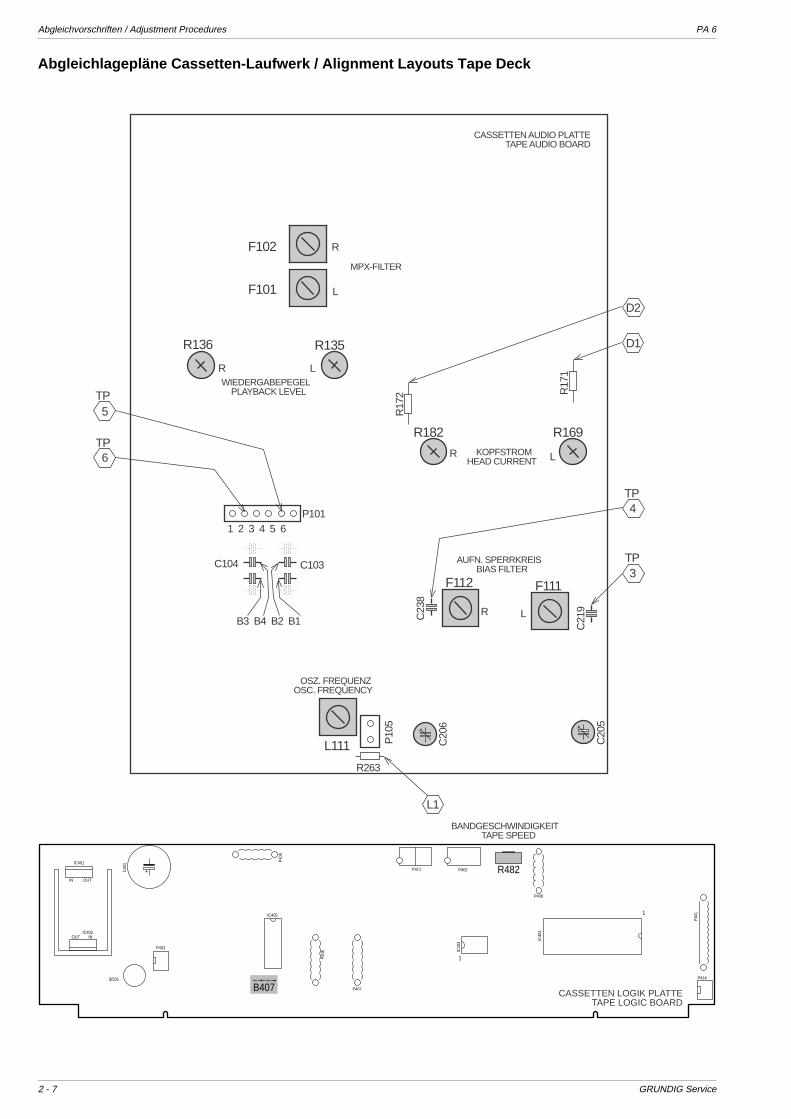
Abgleichvorschriften / Adjustment Procedures PA 6
2 - 7 GRUNDIG Service
Abgleichlagepläne Cassetten-Laufwerk / Alignment Layouts Tape Deck
F102
F101
R
L
R136 R135
LR
R17
2 R17
1
F112 F111
LR
R169R182
LRC23
8
C21
9
C20
5
C20
6
R263
L111
C104 C103
P1011 2 3 4 5 6
P10
5
D1
D2
4
3
TP
TP
L1
B3 B4 B2 B1
TP
5
6
TPWIEDERGABEPEGEL
PLAYBACK LEVEL
KOPFSTROMHEAD CURRENT
AUFN. SPERRKREISBIAS FILTER
OSZ. FREQUENZOSC. FREQUENCY
BANDGESCHWINDIGKEITTAPE SPEED
MPX-FILTER
OUT INIC402
P409
P40
6
C40
1
1
IC40
3
SI501
IC405
P403
B407
R482
P407
P40
8
OUTIN
IC401
P402
P414
1
IC40
4
P40
1
P411
CASSETTEN LOGIK PLATTETAPE LOGIC BOARD
CASSETTEN AUDIO PLATTETAPE AUDIO BOARD
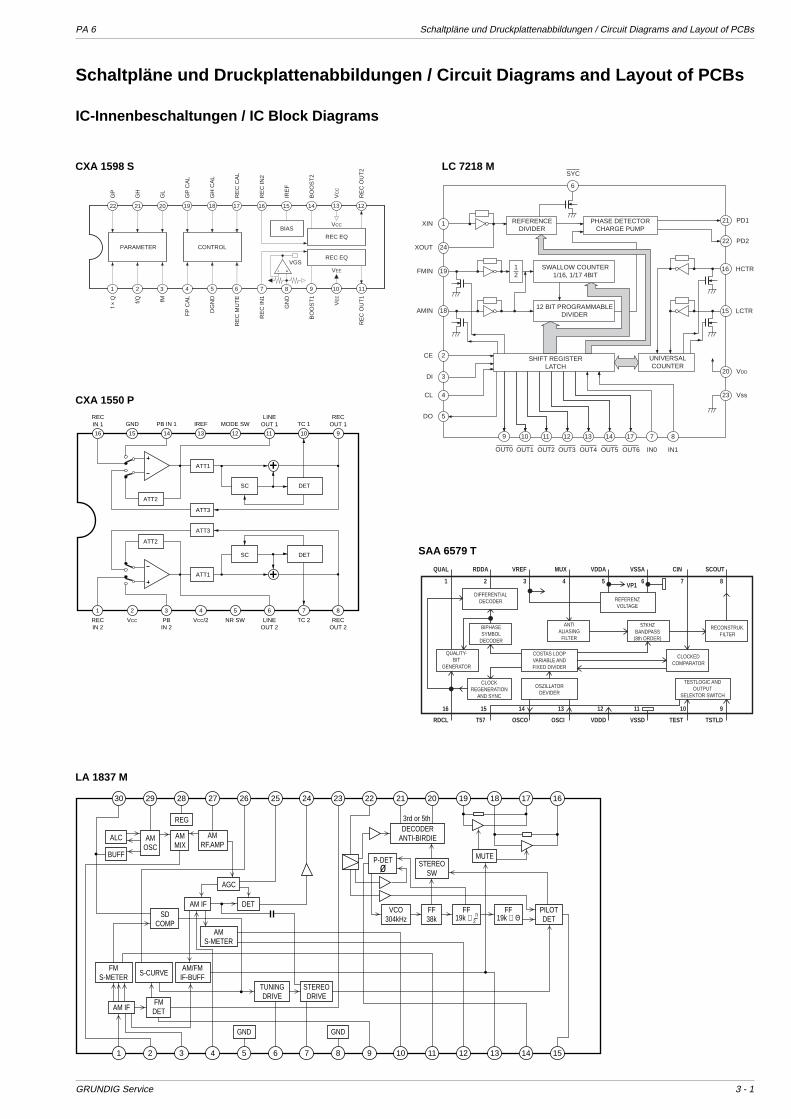
PA 6 Schaltpläne und Druckplattenabbildungen / Circuit Diagrams and Layout of PCBs
GRUNDIG Service 3 - 1
Schaltpläne und Druckplattenabbildungen / Circuit Diagrams and Layout of PCBs
IC-Innenbeschaltungen / IC Block Diagrams
10111213141516
ATT1
SC DET
ATT3
ATT2
ATT1
SC DET
ATT3
ATT2
1 2 3 4 5 6 7 8
RECIN 1 GND PB IN 1 IREF MODE SW
LINEOUT 1 TC 1
RECOUT 1
9
RECIN 2
VCC/2VCC PBIN 2
NR SW LINEOUT 2
TC 2 RECOUT 2
GN
D
BIASREC EQ
RE
C O
UT
1
BO
OS
T1
VE
E
RE
C IN
1 fM
DG
ND
f × Q
PARAMETER CONTROL
REC EQ
VCC
VEE
9 10 112 3 4 5 6 7 81
1213141516171819202122
VGS
FP
CA
L
RE
C M
UT
E
f/Q
IRE
F
RE
C O
UT
2
BO
OS
T2
VC
C
RE
C IN
2
GL
GH
CA
L
GP
GP
CA
L
RE
C C
AL
GH
REFERENCEDIVIDER
PHASE DETECTORCHARGE PUMP
SWALLOW COUNTER1/16, 1/17 4BIT
12 BIT PROGRAMMABLEDIVIDER
SHIFT REGISTERLATCH
UNIVERSALCOUNTER
12
22
16
15
20
23
5
4
3
2
18
19
24
1
1211109 13 14 17 7 8
21
6
PD2
HCTR
LCTR
VDD
Vss
PD1
DO
CL
DI
CE
AMIN
FMIN
XOUT
XIN
OUT3OUT2OUT1OUT0 OUT4 OUT5 OUT6 IN0 IN1
SYC
VP1
CLOCKREGENERATION
AND SYNC
OSZILLATORDEVIDER
TESTLOGIC ANDOUTPUT
SELEKTOR SWITCH
QUALITY-BIT
GENERATOR
COSTAS LOOPVARIABLE ANDFIXED DIVIDER
CLOCKEDCOMPARATOR
BIPHASESYMBOL
DECODER
ANTIALIASING
FILTER
57KHZBANDPASS
(8th ORDER)
RECONSTRUK.FILTER
REFERENZVOLTAGE
DIFFERENTIALDECODER
RDCL T57 OSCO OSCI VDDD VSSD TEST TSTLD
SCOUTCINVSSAVDDAMUXVREFRDDAQUAL
16 12131415 91011
1 2 3 4 5 6 7 8
CXA 1598 S LC 7218 M
CXA 1550 P
SAA 6579 T
LA 1837 M
1 2 3 4 5 6 7 8 9 10 11 12 13 14 15
30 29 28 27 26 25 24 23 22 21 20 19 18 17 16
ALC
BUFF
AMOSC
AMMIX
REG
AMRF.AMP
AGC
DETAM IFSD
COMPAM
S-METER
FMS-METER S-CURVE
AM/FMIF-BUFF
AM IFFM
DET
TUNINGDRIVE
STEREODRIVE
GND GND
STEREOSW
MUTE
VCO304kHz
FF38k
PILOTDET
FF19k ∠ –π2
FF19k ∠ Θ
P-DETø
DECODERANTI-BIRDIE
3rd or 5th
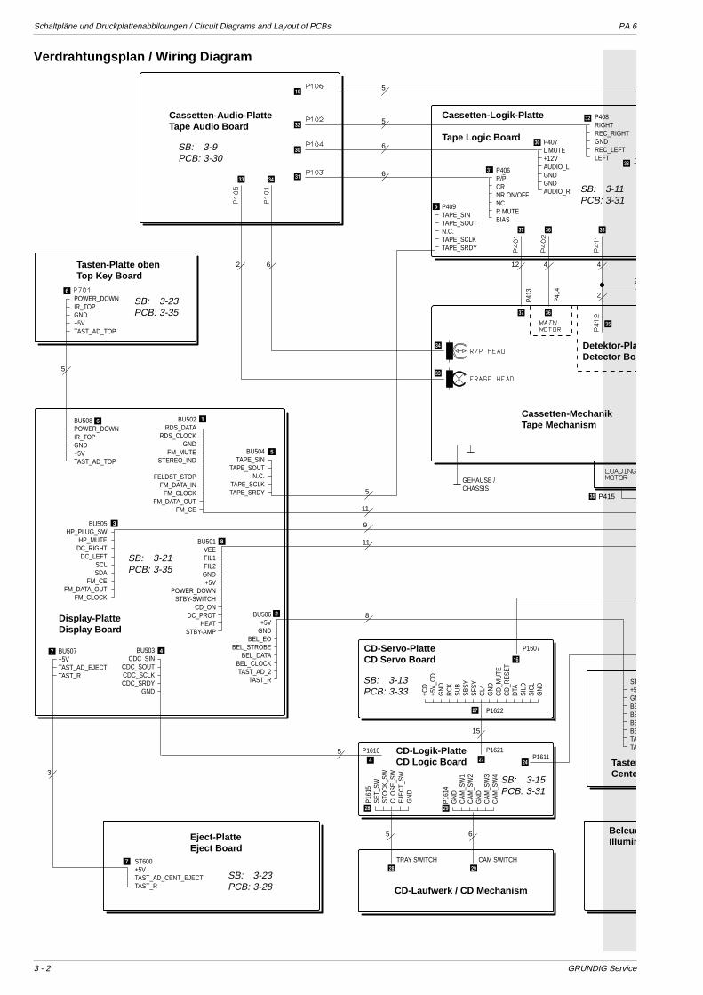
Schaltpläne und Druckplattenabbildungen / Circuit Diagrams and Layout of PCBs PA 6
3 - 2 GRUNDIG Service
5
5
6
6
5
11
9
11
8
5
5 6
15
12 4 4
2
2
62
5
3
P415
CD-Servo-PlatteCD Servo Board
BeleucIllumin
BU503CDC_SIN
CDC_SOUTCDC_SCLKCDC_SRDY
GND
P1607
P1611P1610
P1622
P1621
BU507+5VTAST_AD_EJECTTAST_R
BU508POWER_DOWNIR_TOPGND+5VTAST_AD_TOP
BU502RDS_DATA
RDS_CLOCKGND
FM_MUTESTEREO_IND
FELDST_STOP
FM_DATA_INFM_CLOCK
FM_DATA_OUTFM_CE
BU504TAPE_SIN
TAPE_SOUTN.C.
TAPE_SCLKTAPE_SRDY
BU501-VEEFIL1FIL2GND+5V
POWER_DOWNSTBY-SWITCH
CD_ONDC_PROT
HEATSTBY-AMP
BU506+5V
GNDBEL_EO
BEL_STROBEBEL_DATA
BEL_CLOCKTAST_AD_2
TAST_R ST+5GNBEBEBEBETATA
BU505HP_PLUG_SW
HP_MUTEDC_RIGHT
DC_LEFTSCLSDA
FM_CEFM_DATA_OUT
FM_CLOCK
P409TAPE_SINTAPE_SOUTN.C.TAPE_SCLKTAPE_SRDY
P407L MUTE+12VAUDIO_LGNDGNDAUDIO_R
P408RIGHTREC_RIGHTGNDREC_LEFTLEFT
POWER_DOWNIR_TOPGND+5VTAST_AD_TOP
ST600+5VTAST_AD_CENT_EJECTTAST_R
+CD
+5V_
CD
GN
DR
CK
SUB
SBSY
SFSY
CL4
GN
DC
D_M
UTE
CD
_RES
ETD
TASI
LDSI
CL
GN
D
P161
5SE
T_SW
STO
CK_
SWC
LOSE
_SW
EJEC
T_SW
GN
D
P161
4G
ND
CAM
_SW
1C
AM_S
W2
GN
DC
AM_S
W3
CAM
_SW
4
CD-Laufwerk / CD Mechanism
P413
P414
GEHÄUSE / CHASSIS
TRAY SWITCH CAM SWITCH
P406R/PCRNR ON/OFFNCR MUTEBIAS
(
=
>
>
?
?
=
1
5
7 4
2
4
7
:
8
3
6
6
+
\\
@@
[[
|
|
_
_
_
^
^
]
]
5
Cassetten-Audio-PlatteTape Audio Board
Cassetten-Logik-Platte
Tape Logic Board
Tasten-Platte obenTop Key Board
Display-PlatteDisplay Board
Eject-PlatteEject Board
CD-Logik-PlatteCD Logic Board Tasten
Cente
Cassetten-MechanikTape Mechanism
Detektor-PlaDetector Boa
Verdrahtungsplan / Wiring Diagram
SB: 3-9PCB: 3-30
SB: 3-23PCB: 3-35
SB: 3-21PCB: 3-35
SB: 3-23PCB: 3-28
SB: 3-15PCB: 3-31
SB: 3-13PCB: 3-33
SB: 3-11PCB: 3-31
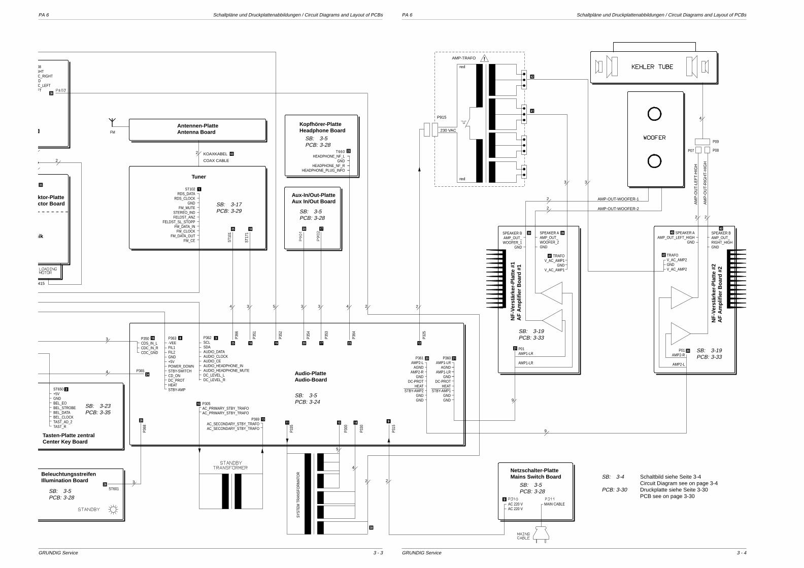
PA 6 Schaltpläne und Druckplattenabbildungen / Circuit Diagrams and Layout of PCBs PA 6 Schaltpläne und Druckplattenabbildungen / Circuit Diagrams and Layout of PCBs
GRUNDIG Service GRUNDIG Service
3
4
3
2
2
34 5 3 3 4 2
2
2
2
9
33
2 2
4
2
4
5
2
9
415
BeleuchtungsstreifenIllumination Board
230 VAC
P915
AMP-TRAFO
red
red
!
AM
P-O
UT-
RIG
HT-
HIG
H
AM
P-O
UT-
LEF
T-H
IGH
AMP-OUT-WOOFER-1
AMP-OUT-WOOFER-2
TRAFOV_AC_AMP2GNDV_AC_AMP2
TRAFOV_AC_AMP1
GNDV_AC_AMP1
P369AC_SECONDARY_STBY_TRAFOAC_SECONDARY_STBY_TRAFO
ST650+5VGNDBEL_EOBEL_STROBEBEL_DATABEL_CLOCKTAST_AD_2TAST_R
08GHTC_RIGHTDC_LEFTFT
P350CDS_IN_LCDC_IN_RCDC_GND
P01AMP1-LR
AMP1-LR
P01AMP2-R
AMP2-L
HEADPHONE_NF_LGND
HEADPHONE_NF_RHEADPHONE_PLUG_INFO
P305AC_PRIMARY_STBY_TRAFOAC_PRIMARY_STBY_TRAFO
SPEAKER BAMP_OUT_WOOFER_1
GND
SPEAKER A AMP_OUT_WOOFER_2GND
SPEAKER AAMP_OUT_LEFT_HIGH
GND
SPEAKER B AMP_OUT_RIGHT_HIGHGND
ST102RDS_DATA
RDS_CLOCKGND
FM_MUTESTEREO_INDFELDST_ANZ
FELDST_SL_STOPPFM_DATA_IN
FM_CLOCKFM_DATA_OUT
FM_CE
AC 220 VAC 220 V
MAIN CABLE
ST601
P366
P351
P352
P354
P353
P364
P325
P335
SYST
EM T
RAN
SFO
RM
ATO
R
P300
T660
P330
P315
P368
P363-VEEFIL1FIL2GND+5VPOWER_DOWNSTBY-SWITCHCD_ONDC_PROTHEATSTBY-AMP
P362SCLSDAAUDIO_DATAAUDIO_CLOCKAUDIO_CEAUDIO_HEADPHONE_INAUDIO_HEADPHONE_MUTEDC_LEVEL_LDC_LEVEL_R
P08P07
P09
ST10
1
ST17
1
FM
P365
P360AMP1-LR
AGNDAMP1-LR
GNDDC-PROT
HEATSTBY-AMP1
GNDGND
P361AMP2-L
AGNDAMP2-R
GNDDC-PROT
HEATSTBY-AMP2
GNDGND
(
8 3
; ~
;
1
3
~
+ , )
, )
/
/
#
,
,
-
9%&"$
!
<
:
<
9
-
V V
1
1
2
2
00
_
_
2
Tasten-Platte zentralCenter Key Board
nik
ktor-Plattector Board
Antennen-PlatteAntenna Board
Tuner
Kopfhörer-PlatteHeadphone Board
Aux-In/Out-PlatteAux In/Out Board
Audio-PlatteAudio-Board
Netzschalter-PlatteMains Switch Board
NF
-Ver
stär
ker-
Pla
tte
#1A
F A
mp
lifie
r B
oar
d #
1
NF
-Ver
stär
ker-
Pla
tte
#2A
F A
mp
lifie
r B
oar
d #
2
KOAXKABEL
COAX CABLE
3 - 43 - 3
SB: 3-4 Schaltbild siehe Seite 3-4Circuit Diagram see on page 3-4
PCB: 3-30 Druckplatte siehe Seite 3-30PCB see on page 3-30
SB: 3-5PCB: 3-24
SB: 3-19PCB: 3-33
SB: 3-23PCB: 3-35
SB: 3-5PCB: 3-28
SB: 3-17PCB: 3-29
SB: 3-5PCB: 3-28
SB: 3-5PCB: 3-28
SB: 3-5PCB: 3-28
SB: 3-19PCB: 3-33
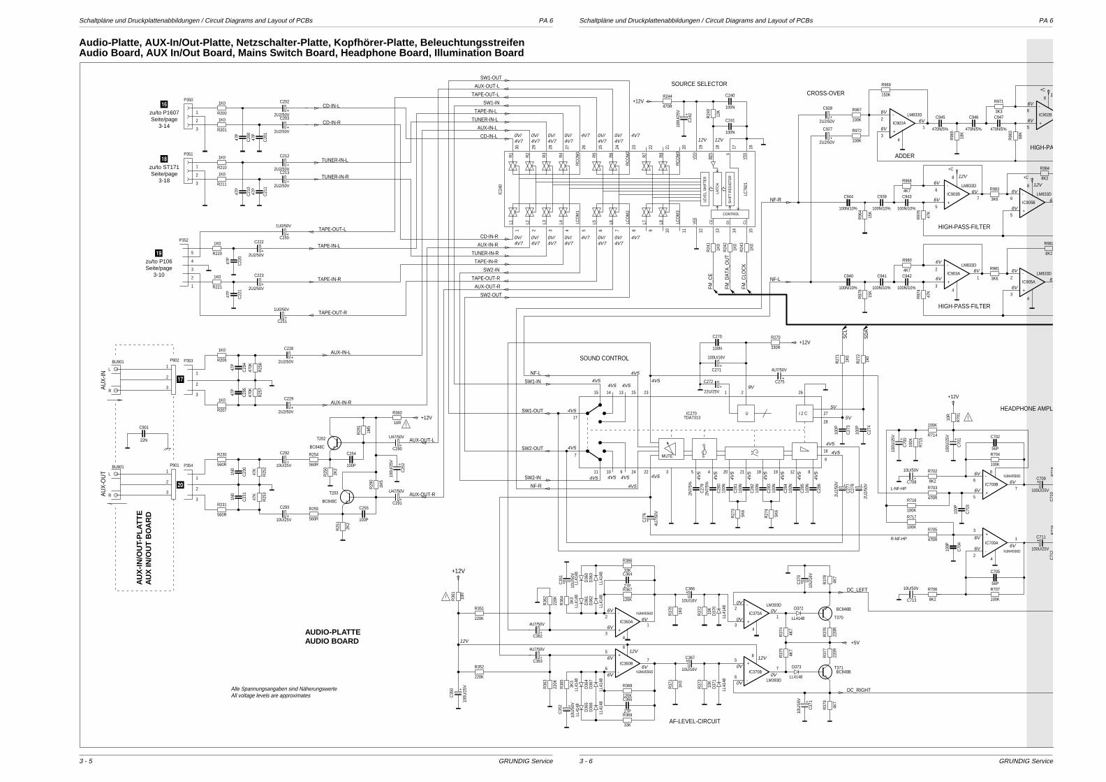
Schaltpläne und Druckplattenabbildungen / Circuit Diagrams and Layout of PCBs PA 6 Schaltpläne und Druckplattenabbildungen / Circuit Diagrams and Layout of PCBs PA 6
GRUNDIG Service GRUNDIG Service
100N
C241
100N
C240
1K0
R24
2
1K0
R24
1
1K0
R24
3
12K
R24
0
LCO
M3
L8L7LCO
M2
L6L5LCO
M1
L4L3L2L1
RC
OM
3
R8
R7
RC
OM
2
R6
R5
RC
OM
1
R4
R3
R2
R1
VE
E
CE
DI
CL
VS
SS
RE
S
VD
D
CONTROL
SH
IFT
RE
GIS
TER
LATC
H
LEV
EL
SH
IFTE
R
LC78
21
IC24
0
+
100U
/25V
C24
2
470R
R244
TUNER-IN-L
TAPE-IN-R
CD-IN-L
FM_C
LOC
K
CD-IN-R
AUX-OUT-L
SW1-IN
TAPE-OUT-L
FM_C
E
FM_D
ATA
_OU
T
SW2-OUT
+12V
TAPE-OUT-R
AUX-OUT-R
TAPE-IN-L
AUX-IN-L
SW1-OUT
TUNER-IN-R
AUX-IN-R
SW2-IN
SOURCE SELECTOR
30 29 28 27 26 25 24 23 22 21 20 19 18 17 16151413121110987654321
+2U2/50V
C213
+2U2/50V
C212
+2U2/50V
C203
+2U2/50V
C202
47P
C20
1
47P
C20
0
47P
C21
047
P
C21
1
1K0
R201
1K0
R200
1K0
R210
1K0
R211
P351
P350
TUNER-IN-L
CD-IN-L
CD-IN-R
TUNER-IN-R
1
2
3
1
2
3
47P
C22
1
1K0
R221
47P
C22
01K0
R220
P352
+
1U0/50V
C251
+
1U0/50V
C250
+2U2/50V
C222
+2U2/50V
C223TAPE-IN-R
TAPE-OUT-L
TAPE-OUT-R
TAPE-IN-L5
4
3
2
1
47P
C29
4
47P
C29
5
+
100U
/25V
C25
2
2K2
R25
12K
2
R25
0
470K
R25
6
1K0
R206
1M5
R29
0
470K
R25
7
1K0
R207
1M5
R29
1
560R
R254
560R
R255
47K
R25
3
47K
R25
2
10R
R360
+10U/25V
C293
C901
+10U/25V
C292
+
U47/50V
C291
+
U47/50V
C290
+2U2/50V
C228
+2U2/50V
C229
1N0
C23
1
100P
22N
C255
100P
C254
1N0
C23
0
560R
R231BC848C
T203
P354
P353P902
P901
BU901
L
R
L
R
BU901 560R
R230
BC848C
T202 AUX-OUT-L
+12V
AUX-OUT-R
AUX-IN-L
AUX-IN-R
AU
X-O
UT
AU
X-IN
3
2
1
3
2
1
3
2
1
3
2
1
4K7
R968
100N/10%
C943 3K6
R983-
+
IC905B
LM833D
47K
R97
6
-
+
IC903B
LM833D
100N/10%
C940
15K
R97
8 100N/10%
C9414K7
R980
100N/10%
C942 3K6
R981-
+
IC905A
LM833D
47K
R97
4
-
+
IC903A
LM833D
100N/10%
C939
15K
R96
4100N/10%
C944
8K2
R982
8K2
R984
470N/5%
C945
18K
R96
5 470N/5%
C946
-
+
IC902B
68K
R96
3470N/5%
C9473K3
R971
-
+
IC902A
LM833D
150K
R969
100K
R967
100K
R972
+2U2/50V
C927
+2U2/50V
C928
+C
+C
+C
NF-L
NF-R
HIGH-PAADDER
HIGH-PASS-FILTER
HIGH-PASS-FILTER
CROSS-OVER
1
43
2
5
6
8
7 6
5
8
7
3
2
4
1
8
5
6
3
2
4
1
100N
C28
6
100P
C27
3
100P
C27
4
100N
C28
2
100N
C28
1
2N7/
5%
C28
0
100N
C28
310
0N
C28
410
0N
C28
5
2N7/
5%
C27
9
100P
C70
410
0P
C70
3
27P
C365
27P
C364
C71
0
56P
C702
56P
C705
1k0
R27
2
1K0
R27
1
330R
R270
5K6
R27
4
5K6
R27
3
100K
R707
100K
R704
8K2
R706
8K2
R702
470R
R703
470R
R705
10K
R37
3120K
R368
120K
R367
3K3
R36
5
33K
R366
1K0
R37
1
220K
R36
3
33K
R369
1K0
R37
0
10K
R37
2
3K3
R36
4
220K
R36
2
4K7
R37
4
220R
R37
7
4K7
R37
9
4K7
R37
8
220R
R37
6
4K7
R37
5
I 2 C
26
27
28
16
6
812191821204
212325131415
53222491011
7
17U
MUTE
TDA7313IC270
10R
R36
1
10R
R70
1
BC848BT371
+
10U/50V
C708
+
100U/25V
C711
R71
8
+10
0U/2
5V
C35
0
+
100U/25V
C709
100K
R716
R71
9
100K
R71
5
+22U/25V
C272
+
4U7/
50V
C27
6
+
100U/16V
C271
+2U
2/50
V
C27
8+
2U2/
50V
C27
7
+
4U7/50V
C363
+
4U7/50V
C362
+
10U/50V
C713
+
4U7/50V
C275
+
10U/16V
C366
+
10U/16V
C367
C71
2
+
10U
/16V
C37
0
+
100U
/25V
C70
1+
100U
/25V
C70
0
+
10U
/16V
C37
1
-
+
NJM4556D
IC700A
-
+
NJM4556D
IC700B
-
+
NJM4556D
IC360A
-
+
NJM4556D
IC360B
-
+
LM393D
IC370B
-
+
LM393D
IC370A
100K
R717
100K
R714
100N
C270
LL4148
D373
LL41
48
D36
7
LL41
48
D36
6
LL41
48
D36
5
LL41
48
D36
4
LL41
48
D36
1
LL41
48
D36
3
LL41
48
D36
0
LL41
48
D36
2
LL41
48
D37
1
LL41
48
D37
0
LL4148
D372 BC848B
T370
220K
R352
220K
R351
+
10U
/50V
C35
1
+10
U/5
0V
C35
2
L-NF-HP
R-NF-HP
SC
L
SW1-IN
SD
A
SW2-OUT
+12V
+12V
+12V
DC_LEFT
+5V
SW1-OUT
NF-L
NF-R
DC_RIGHT
SW2-IN
SOUND CONTROL
AF-LEVEL-CIRCUIT
HEADPHONE AMPL
3
2
1
8
6
5
7
7
6
5
43
2
1
7
4
8
8
1
6
5
3
2
AUDIO-PLATTEAUDIO BOARD
AU
X-I
N/O
UT-
PL
AT
TE
AU
X IN
/OU
T B
OA
RD
12
12V
12V
6V
6V
6V 6V
6V
6V
6V
6V6V
6V
6V
6V
6V
6V
6V
6V
6V
6V
6V
6V
6V
6V
6V
12V
6V
6V
6V 0V
0V
0V
0V
0V
0V
6V
6V
6V
12V12V
4
9V4V5
4V5
4V5
4V5 4V5 4V5
4V5
4V5
4V5
4V5
5V
5V
4V5
4V5
4V5
4V5
4V5
4V5
4V5
4V5
4V5 4V5
4V5
4V5
0V/4V7
4V7 4V7
4V7 4V712V 12V
0V/4V7
0V/4V7
0V/4V7
0V/4V7
0V/4V7
0V/4V7
0V/4V7
0V/4V7
0V/4V7
0V/4V7
0V/4V7
Alle Spannungsangaben sind NäherungswerteAll voltage levels are approximates
3 - 63 - 5
Audio-Platte, AUX-In/Out-Platte, Netzschalter-Platte, Kopfhörer-Platte, BeleuchtungsstreifenAudio Board, AUX In/Out Board, Mains Switch Board, Headphone Board, Illumination Board
(zu/to P1607Seite/page
3-14
~zu/to ST171Seite/page
3-18
+zu/to P106Seite/page
3-10
)
,
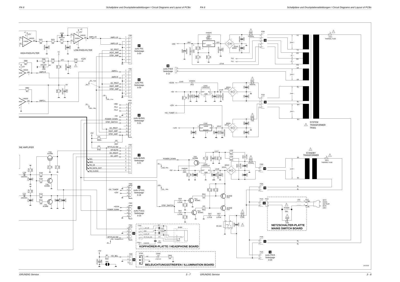
PA 6 Schaltpläne und Druckplattenabbildungen / Circuit Diagrams and Layout of PCBs PA 6 Schaltpläne und Druckplattenabbildungen / Circuit Diagrams and Layout of PCBs
GRUNDIG Service GRUNDIG Service
P325
100N
C93
6
100N
/50V
C90
1
100N
/50V
C90
022
N
C91
0
22N
C91
1
100N
C91
4
100N
C91
3
100N
C93
0
100N
C92
3
100N
C92
4
22n
C92
1
22n
C92
0
100N
C93
4
100N
C93
1
12k
R90
1
220R
R90
2
10k
R90
0
100K
R91
0
100K
R91
1
10K
R92
2
47K
R92
3
18K
R92
5
470R
R921
470R
R920
1K0
R912
1K0
R913
100K
R91
510
0K
R91
4
BC848BT920
3
2
1GNDOUT IN
L7805ACD2T
SN
IC910
3
2
1GNDOUT IN
L7805ACD2TIC920
SI910
15V3 ~
GR
GR1
2
T800mAL
SI920
T315mAL
102¡CTHERMAL FUSE
SI930
T1AL
SI940
T2,5AL
P335
1 2 3
45
REL900
1N4004G
D900
1N4004G
D923
+
10U
/50V
C90
3
+
4700
U/2
5V
C91
2
SI900
T500mAL
+
4700
U/2
5V
C93
2
P369
BN
BN
BL
BL
+
2U2/
50V
C92
6
+
470U
/63V
C90
2
+
1U0/
50V
C91
5
INOUTADJUST
IC900LM337T ~
~
+
-
DF04SBR900
~
~
+
-
DF02SBR920
~
~
+
-
DF02SBR930
~
~
+
-
DF02SBR910
P315 P310 P311
S801
L301
LL4148
D912
C801
LL41
48
D92
0
LL41
48
D92
1
LL4148
D922
LL4148
D910
LL4148
D911
P300
BZX
84C
4V7
D90
1
BC848CT911
3300
P
C95
0
P305
BC848CT912
BC858BT913
BC858BT914
+
1000
U/2
5V
C92
2
0RR90
5
ADJUSTINOUT
3
2
1
IC930
LM340
1N4004G
D913
4
3
2
1
P330
+20V
+5V_TUNER
POWER_DOWN
STBY_SWITCH
+DCIN
+12V
FIL2
FIL1
-VEE
+5V
+5V
14.03.00
4
3
2
1
P365
POWER_DOWN
+DCIN
4
3
2
1
3
2
1
P366
+20V
+5V_TUNER
11
10
9
8
7
6
5
4
3
2
1
P363
1K0
R937
DC_PROT
POWER_DOWN
STBY_SWITCH
HEAT_AMP
FIL2
FIL1
STBY_AMP
-VEE
+5V
STANDBY
SYSTEMTRANSFORMERTR301
TRANSFORMER
3 2
1
2
1
2
1
2
21
1
2
1
2
1
5
4
3
2
1
P362
HP-MUTE
FM_CLOCK
SCL
SDA
FM_CE
FM_DATA_OUT
HP-PLUG-SW
HP-PLUG-SW
DC_LEFT
DC_RIGHT
9
8
7
6
5
4
3
2
1
P361AMP2-L
DC_PROT
HEAT_AMP
STBY_AMP
AMP2-R
9
8
7
6
5
4
3
2
1
P360
DC_PROT
AMP1-LR
AMP1-LR
HEAT_AMP
STBY_AMP
9
8
7
6
5
4
3
2
1
9V8 ~
16V3 ~
11V5 ~
35V5 ~
2V ~
2V ~
115¡CTHERMAL FUSE
P368+5V_BEL0R
R924
LBR1
+5V
POWER
NETZMAINSSECTEURRETE230V~
3300P
K
1
2
BN
BL
LTA673-R
CD640
3
2
1ST601
82R
CR640+5V
1
2
ST661-122n
CC602
4n7
CC603
54
32
1
BU661
4
3
4n7
CC601
HP_PLUG_SW
R_NF_HP
CHASSIS
GND
L_NF_HP
ST660
10R
R383
905B
LM833D
47N
/5%
C94
8
905A
LM833D
+
100U/25V
C361+
100U
/25V
C36
0
+
100U
/25V
C38
5
8K2
R982
8K2
R98410K
R381
-
+
IC902B
LM833D
18K
R975
10K
R382
18K
R979
18K
R97768N/10%
C949
12N
/5%
C93
8
-
+
IC904A
LM833D
10K
R38
4
10K
R38
5
AMP2-L
+C
C
+C
+C
+12V
AMP1-LR
AMP2-R
LOW-PASS-FILTERHIGH-PASS-FILTER
8
7
4
1
1
4
8
3
28
5
6
56P
C70
656
P
C70
7
2N2
C71
0
68R
R708
68R
R710
1K0
R709
1K0
R711
100K
R71
3
10K
R71
2
47K
R720
BC858BT702
+
100U/25V
C711
100K
R71
8
+
100U/25V
C709
100K
R71
9
2N2
C71
2
BC848BT701
BC848BT700
4
3
2
1
P364
+5V
ONE AMPLIFIER
47K
R939Y
KOPFHÖRER-PLATTE / HEADPHONE BOARD
BELEUCHTUNGSSTREIFEN / ILLUMINATION BOARD
NETZSCHALTER-PLATTEMAINS SWITCH BOARD
1V5
0V Stby
5V
4V2 Stby
0V
5V Headphone in
5V
0V Prot.
5V
0V Stby
5V
0V
Heat
12V
12V6V
6V
6V
6V
6V
6V
6V
6V
6V
6V
12V
12V
11V7
13V6
20V3
11V5
11V0
-32V
-27V4
-30V
47U
/16V
C99
9+
3 - 83 - 7
-zu/to P01
Seite/page3-20
.zu/to P01
Seite/page3-20
8zu/to BU501Seite/page
3-21
3zu/to BU505Seite/page
3-21
;zu/to ST101Seite/page
3-18
:zu/to P1611Seite/page
3-15
zu/to P403Seite/page
3-12
#zu/to P915Seite/page
3-20
/
<
"
9
!
$
&
%
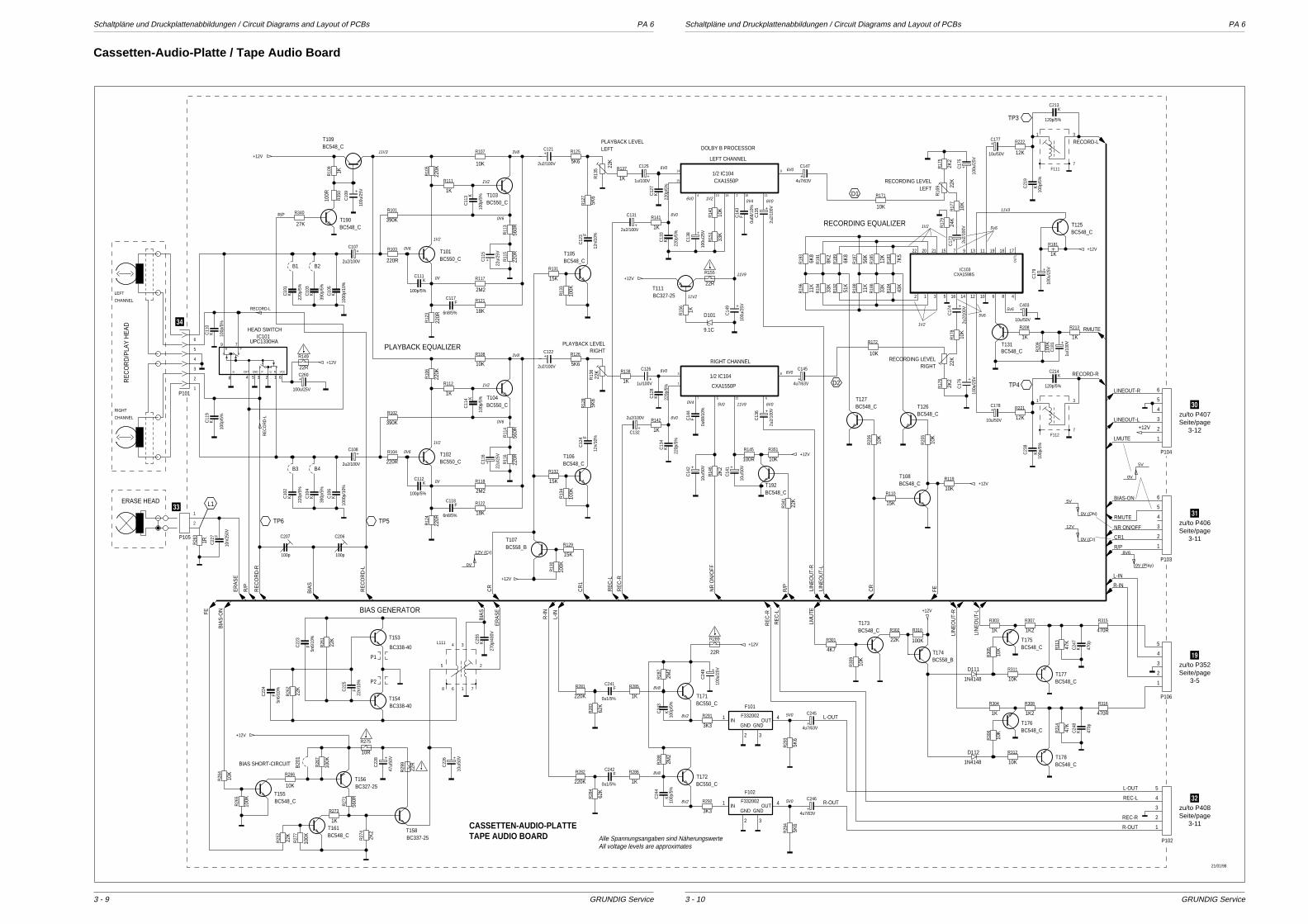
Schaltpläne und Druckplattenabbildungen / Circuit Diagrams and Layout of PCBs PA 6 Schaltpläne und Druckplattenabbildungen / Circuit Diagrams and Layout of PCBs PA 6
GRUNDIG Service GRUNDIG Service
+12V
22R
R289
BC548_CT178
+12V
47K
R31
4
K 470p
C24
8
BC548_CT176
1K2
R308
1K
R304
470R
R316
10K
R312
10K
R30
6
1N4148
D112
LIN
EO
UT-
R
LIN
EO
UT-
R
10K
R30
9
1N4148
D111
10K
R30
5
10K
R311
470R
R315
1K
R303
BC558_BT174
1K2
R307
BC548_CT173
22K
R302
100K
R310
BC548_CT175
K 470p
C24
7
4K7
R301
47K
R31
3
BC548_CT177
R-IN
L-IN
5K6
R29
4
+4u7/63V
C246
3K3
R2925K
6
R29
3
+4u7/63V
C245
3K3
R291+
100u
/25V
C24
9
K10
0p/5
%
C24
4
2M2
R28
7
F
0u1/5%
C242
62K
R28
3
BC550_CT172
220K
R281
1K
R286
220K
R282
1K
R285
BC550_CT171
L-OUT
L-OUT
REC-LR-OUT
R-OUT
REC-R
RE
C-L
RE
C-R
R-IN
+12VLINEOUT-L
LINEOUT-R
F
0u1/5%
C241
K10
0p/5
%
C24
3
LIN
EO
UT-
L
62K
R28
4
L-IN
2M2
R28
8
P104
1
2
3
4
5
6
P102
1
2
3
4
5
P103
1
2
3
4
5
6
P106
1
2
3
4
5
+12V
B20
1
2K2
R27
4
22K
R25
2
100K
R27
7
1K
R273
560R
R27
1
10K
R26
4
100K
R26
5
10K
R266
BC548_CT155
100K
R26
7 +47
u/50
V
C22
8
22R
R29
9
BC327-25T156
10R
R275
BC548_CT161
BC337-25T158
K
270p
/400
V
C25
5
L111
1
2
34
5
6 78
22K
R26
2
F22
n/10
%
C22
5
22K
R26
1
BC338-40
T153
+10
u/50
V
C22
6
F5n
6/10
%
C22
3
BC338-40T154
F5n
6/10
%
C22
4
BIA
S
ER
AS
E
K
120p/5%
C213
12K
R222
F111
K
120p/5%
C214
K10
0p/5
%
C21
9
K10
0p/5
%
C23
8
F112
22K
12K
R221
2K2
R17
6
+1u
/100
V
C18
110
0K
R20
9
BC548_CT131
1K
R208
1K
R213
22K
R16
9
10K
R17
8
+
100u
/25V
C17
5
+
10u/50V
C177
+
10u/50V
C178
+
10u/50V
C403
10K
R171D1
2K2
R17
5
+10
0u/2
5V
C17
610
K
R17
7
+2u
2/10
0V
C17
4+
C17
324
K
R17
9
+12V
15K
R11010K
R119BC548_CT108
10K
R20
5
10K
R20
6
BC548_CT127
BC548_CT126
43K
R18
433
K
R18
611
K
R18
8
51K
R19
233
K
R19
411
K
R19
6
7K5
R18
312
K
R18
556
K
R18
7
6K8
R18
9
6K8
R19
3
BC327-25T111
9.1C
D101
F
0u68
/10%
C14
3
33K
R15
1
+10
0u/2
5V
C14
9
10K
R14
3
1KR15
6
22R
R155
+2u
2/10
0V
C13
5
+10
0u/2
5V
C13
8
K 220p
/5%
C12
8
K
220p
/5%
C13
4
1K
R138
+1u/100V
C126
+
2u2/100V
C132 1K
R142
RE
C-R
RE
C-L
K
220p
/5%
C12
7
K
220p
/5%
C13
3
22K
R13
6
22K
R13
5
1K
R137
+1u/100V
C125
+2u2/100V
C131
BC558_BT107
100K
R13
0
+12V
1K
R141
15K
R129
R/P
+12V
100K
R13
4
15K
R132
5K6
R12
8F
12n/
10%
C12
4
5K6
R126
10K
R108
+
22u/
25V
C11
6
220R
R11
6
560R
R11
4
2M2
R118
18K
R122
220R
R12
4
K
100p
/5%
C11
4
1K
R112
BC550_CT104
220K
R10
6390K
R102
+
2u2/100V
C122
F
6n8/5%
C118
K
100p/5%
C112
BC548_CT106
BC550_CT102
220R
R104
100K
R13
3
15K
R131
5K6
R12
7F
12n/
10%
C12
3
5K6
R125
+10
0u/2
5V
C10
9
27K
B1 B2
B3 B4
R340
100R
R35
01KR10
9
10K
R107
+
22u/
25V
C11
5
220R
R11
5
560R
R11
3
2M2
R117
18K
R121
220R
R12
3
K
100p
/5%
C11
3
1K
R111
BC550_CT103
100R
R145
10K
R351
220K
R10
5
+12V
22K
R34
1
390K
R101
+
10u/
50V
C14
2
+
2u2/100V
C121
F
6n8/5%
C117
F
0u68
/10%
C14
4
+
10u/
50V
C14
1
10K
R172
K
100p/5%
C111
+2u
2/10
0V
C13
6
BC548_CT192
+4u7/63V
C145
8K2
R19
1
+4u7/63V
C147
2K2
R14
6
BC548_CT105
BC548_CT190
BC550_CT101
+12V
BC548_CT109
220R
R103
+12V22R
R149
+
100u/25V
C260
K
100p
/5%
C11
9K 10
0p/5
%
C11
0
K
390p
/5%
C10
3
K
1000
p/10
%
C10
5
K
220p
/5%
C10
1
P1011
2
3
4
5
6
+
2u2/100V
C108
+
2u2/100V
C107
RECORD-L
RECORD-L
LIN
EO
UT-
L
RECORD-R
RE
CO
RD
-R
RE
CO
RD
-L
21/01/98
PLAYBACK EQUALIZER
62 13548
79
7
31
7
31
8V2
8V8
8V8
5V0
5V0
8V2
P2
P1
HEAD SWITCH
LMU
TE
CR
CR1
LMUTE
R/P
NR ON/OFF
RMUTE
RMUTE
BIAS-ON
FER/P
NR
ON
/OFF
CR
1
CR
R/P
RECORDING EQUALIZER
DOLBY B PROCESSOR
RIGHT
LEFTPLAYBACK LEVEL
PLAYBACK LEVEL
RIGHTRECORDING LEVELRIGHT CHANNEL
LEFT CHANNEL
CASSETTEN-AUDIO-PLATTETAPE AUDIO BOARD
BIAS SHORT-CIRCUIT
BIAS GENERATOR
CHANNEL
RIGHT
CHANNEL
LEFT
RE
CO
RD
/PLA
Y H
EA
D
ERASE HEAD
1
3
7 5 12 6
8
4 13 16 2 10 11
9
15
14
OU
TL
CXA1598SIC103
CXA1550P
CXA1550P
1/2 IC104
1/2 IC104
UPC1330HAIC101
D2
TP3
TP4
2u2/
100V
+12V
BC548_CT125
+10
0u/2
5V
C17
9
1K
R181
PR
CHT GG P RGND VCC
1713 11 19 189715212022
4121416 10 6 85312
K
390p
/5%
C10
4
K
1000
p/10
%
C10
6
K
220p
/5%
C10
2
RE
CO
RD
-L
ER
AS
E
BIA
S-O
NFE
F332002IN
GND GNDOUT1
2 3
4
F101
F332002IN
GND GNDOUT1
2 3
4
F102
P105
1
2
1RR26
3 F
10n/
250V
C22
7
L1
100p
C207
100p
C206
BIA
S
TP6 TP5
LEFTRECORDING LEVEL
8V6
0V (Play)
5V
0V
5V
0V (ON)
12V
0V (Cr)
12V (Cr)
0V
Alle Spannungsangaben sind NäherungswerteAll voltage levels are approximates
1V2
0V6
1V2
0V6
0V
11V3 3V8
0V6
0V6
0V
3V8
1V2
1V2
6V0
6V0 1V2
11V9
11V95V0
11V2
6V0 6V0
6V0
6V0
0V4
0V4
5V6
11V3
5V65V6
1V2
6V0
6V0 6V0
1V2
3 - 103 - 9
Cassetten-Audio-Platte / Tape Audio Board
@zu/to P407Seite/page
3-12
[zu/to P406Seite/page
3-11
+zu/to P352Seite/page
3-5
\zu/to P408Seite/page
3-11
^
]

PA 6 Schaltpläne und Druckplattenabbildungen / Circuit Diagrams and Layout of PCBs PA 6 Schaltpläne und Druckplattenabbildungen / Circuit Diagrams and Layout of PCBs
GRUNDIG Service GRUNDIG Service
A A
A
A
A
AA
A
A
A
BC558_BT419
BC548_BT415
ALC IN2
ALC IN1
NONALC IN2
NONALC IN1
IN1
RE
CIN
2R
EC
OU
T1O
UT2
PR
EP
RE
NONALCALC/
REC2
REC1
MUTEREC.
DETALC
TA8135P
IC405
1
23
456
7
8
9
10
11 12 13
14
15
16
A
A
BC548_BT416
R431
10K
+C
431
100u
/25V
F
0u1/
10%
C40
9
+C433
2u2/100V
D414
1N4148
+5V
B40
7
R429
10K
R410
22K
F
0u1/10%
C413
R46
8
22K
R462
22K
R47
3
3K6
R/P
CR
1
P4021
2
3
4
R447
100K
R46
9
3K6
R471
3K6
R472
3K6
+C434
2u2/100V
R47
5
270
+
4u7/63V
C437
K
C428
220p/5%
K
C426
220p/5%
BC640T411
R45
8
4K7
+C
429
100u
/25V
+5V
+12V
BC548_BT421
R459
22K
R46
1
47K
R46
4
22K
COUT IN
LM340IC402
R48
6
22K
+12V
R465
4K7+12V
BC548_CT402
R47
6
100K
R466
4K7
R48
9
47K
P4031
2
BC640T403
KC427
220p/5%
R48
8
47K
BC548_BT407
KC425
220p/5%
R43
3
10K
+
C412
100u/25V
R44
6
10K
R432
15K
R444
15K
R48
1
10K
F
0u1/
10%
C40
8
D40
8
4.3C
D40
9
BA
T42
+C
414
2u2/
100V
F
0u1/10%
C415
BC548_CT417
R463
22K
D41
1
4.3C
+12V
F
0u1/
10%
C40
5
F
0u1/
10%
C41
1
R47
8
10K
R47
9
10K
BC639T414
+12V
A
+12V
+5V
R43
0
10K
R426
3K3
R423
3K3
R42
5
10K
R42
2
10K
R47
7
10K
D415
1N4148
D424
1N4148
D417
1N4148
R412820
D40
3
1N41
48
BC327-25T404
A
CR
BC548_BT406
BC548_BT422
BC548_BT401
F
0u1/
10%
C40
3
+5V
R42
7
4K7
+5V
R428
1K
R421
680
R424
680
R41
4
220K
R41
3
330K
R41
5
100K
R41
6
10K
R40
5
22K
+5V
SR
DY
CLK
SIN
SO
UT
RE
SE
T
VC
C
VS
S
VR
EF
DO
LBY
/TY
PE
XO
UT
XIN
M37471-M4-458SP
IC404
1
234 5
6
7
8
9 10 1112
13
14 151617 1819 20 21 2223 2425
26
27
28
29
30 3132 33
34 4235363738394041
P40
71 2 3 4 5 6
+5V
+12V
+5V
PD
+5V
BC548_BT408 T800mA
SI501D402
1N4148R406
47K
R420
33
R404
47K
R40
1
470
R402
470
R47
4
2M2
P40
91 2 3 4 5
P40
6
123456
P412
1
2
+12V
P401
1
2
3
4
5
6
7
8
9
10
11
12
S10011
23
R41
7
10K
D41
2
BA
T42
P408
1
2
3
4
5
F
0u1/
10%
C40
7
COUT IN7805CTIC401
F
0u1/
10%
C40
2
F
0u1/
10%
C41
9
F
0u1/
10%
C40
6
+
10u/50V
C432
P4111
2
3
4
R41
8
10K
D40
7
1N40
04
+
4u7/63V
C436
D40
6
1N40
04
D427
1N4148
D40
5
1N40
04
R48
3
2K2
D40
4
1N40
04
4K7
R48
2+
C40
1
4700
u/25
V
R457
47K
R41
9
10K
D426
1N4148
R452
1K2
R45
6
10K
R44
8
4K7
R454
1K
R44
9
4K7
R48
5
22K
R45
3
10K
R451
1K2
R48
4
22K
R455
1K
D42
1
1N41
48
R40
3
10K
D41
8
1N41
48
D42
2
1N41
48
D41
9
1N41
48
D428
1N4148
BC548_BT409
D425
1N4148
BC639T412
BR412
D413
1N4148
BC327-25T405
4.00MHzF401
BC640T413
BC639T423
+
C40
4
0u47
/100
V
Vcc
TEST
SCL
SDA Vss
A2
A1
A0
X24C04PIC403
1
2
3
45
6
7
8
21/01/98
MECHANISM
TAPE DRIVEDRIVER
SOLENOID 1
DRIVER
SOLENOID 2
MOTOR DRIVER
REC-R
R-OUT
REC-L
L-OUT
REC-R
REC-F
CR
TAPE
FF/REW DETECT
PLAY DETECT
P2
P1
REEL-F
REEL-R
AU
DIO
R
AU
DIO
L
LMU
TE
SR
DY
CLK
SIN
SO
UT
NR
ON
/OFF
RM
UTE
BIA
S-O
N
CAPSTANMOTOR
P2
P1
ICICHALLHALL
-
+
B
A
SL_
IN
SL_
OU
T
TRAYMOTOR
+12V
CASSETTEN-LOGIK-PLATTETAPE LOGIC BOARD
DETEKTOR-PLATTEDETECTOR BOARD
Alle Spannungsangaben sind NäherungswerteAll voltage levels are approximates
7.5V (IN) 7.5V (OUT)11.0V (STOP)
7.5V (IN) 0V (OUT) 0V (STOP)
0V (IN)7.5V (OUT) 0V (STOP)
7.5V (IN) 6.8V (OUT)11.0V (STOP)
6.8V (IN) 7.5V (OUT)11.0V (STOP)
15V3 ~
20V0
14V9
5V
0V
5V
0V (ON)5V
0V12V
0V (Cr)
8V6
0V (Play)
5V (PLAY)
0V
9V3
9V3
2V8
2V8 0V5
0V52V8
2V8
2V8
2V8
2V8
0V
Cassetten-Logik-Platte, Detektor-Platte / Tape Logic Board, Detector Board
3 - 123 - 11
\zu/to P102Seite/page
3-10
zu/to TR301Seite/page
3-7
[zu/to P103Seite/page
3-10
5zu/to BU504Seite/page
3-21
@zu/to P104Seite/page
3-10
_
|
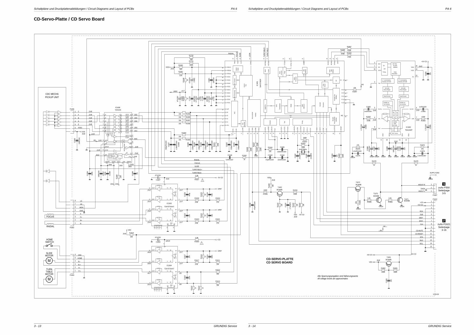
Schaltpläne und Druckplattenabbildungen / Circuit Diagrams and Layout of PCBs PA 6 Schaltpläne und Druckplattenabbildungen / Circuit Diagrams and Layout of PCBs PA 6
GRUNDIG Service GRUNDIG Service
1
2
34
5
6
7
8
9
1011
12
13
1415
16
1
2
3
4
5
6
7
8 9
10
11
12
131415
16
17 18
19
20 21 2223 24 25
26 27 28
29
30
31
32
33 34
35 36 3738
39
40
41
42
43
444546
47
48
49
505152 53 54
55
56
5758
59
6061
62
63
64
1
2
3
4
5 6
7
8
9 10 11 12
13
14
15
16
1
2
34
5
6
7
8
9
1011
12
13
1415
16
10
9
8
7
6
5
4
3
2
1
1
2
3
8
7
6
5
4
3
2
1
6
5
4
3
2
1
7
6
5
4
3
2
1
1
2
3
45
6
7
8
9
10
11
12
13
14
15
16
17
18
19
20
21
22
23 24
25
2627
28
15
14
13
12
11
220p
/5%
/16V
C16
54
220p
/5%
/16V
C16
53
10k R1655
I-i
I-i
I+i
I+i
OUT-
OUT-
OUT+
OUT+
GND
VP
IN-
IN-
IN+
IN+
NCNCNCNCNC
+
+
-
-
TDA7073A/AT
IC1603
NC
Pro
cess
orA
udio
Det
ect
Pea
k
Dem
odul
ator
EFM
SR
AM
Pro
cess
or
Sub
code
RA
MA
ddre
sser
RC
K
SU
B
SFS
Y
SB
SY
Tim
ing Inte
rface
Mic
roco
ntro
ller
Dec
oder
STA
TUS
V5
V4
V3
V2
V1
Inte
rface
Ver
satil
e P
ins
Kill Kill
/RE
SE
T
CL4
CL1
1
CL1
6
CR
OU
T
CR
IN
SE
LPLL
TES
T3
TES
T2
TES
T1
Test
Dig
ital P
LL
Fron
tend
Iref
ISLI
CE
HFR
EF
HFI
N
Inte
rface
Mic
roco
ntro
ller
SIL
D
RA
B
SD
A
SC
L
Vre
fG
ener
ator
VR
H
AD
CR
2
R1
VRL
D1
D2
D3
D4
IrefT
Ctrl
. Fun
ctio
n
Par
tC
ontro
l
Pre
-Pro
cess
ing
stag
esO
utpu
t
Con
trol
Mot
or
Cor
rect
orE
rror
Flag
s
Inte
rface
EB
U
Inte
rface
Dat
aS
eria
l
EF
DA
TA
WC
LK
SC
LK
DO
BM
C2F
AIL
CFL
G
MO
TO2
MO
TO1
LDO
N
SL
FORA
VDDDc3
VDDDp2
VDDDp1
VSSD4
VSSD3
VSSD2
VSSD1
VDDA2
VDDA1
VSSA3
VSSA2
VSSA1
SA
A73
78G
P
IC16
01
220p
/5%
/16V
C16
55
220p
/5%
/16V
C16
52
220p
/5%
/16V
C16
51
220p
/5%
/16V
C16
56
10k R1656
220k
R16
51
1n/5%/16V
C1646
47p/5%/16V
C1643
22n/5%/16V
C1644
100n/5%/16V
C1645
1k
R1645
22k
R1644
560p
C16
26
1.8n
C16
23
5.6n
C16
24
10n
C16
211k
R16
25
1k
R16
226.8k
R1626
27k
R1624
6.8k
R1623
27k
R1621
+
47U/16V
C1627
3.3R
R1627
+
47U
/16V
C16
62
10R
R1662
10N
/16V
C16
61
47R
R1661
470R
R1669470R
R1668 470R
R1667
putout
swswputout
left rgt
curr.sinkscalibr.
curr.sources curr.sources16(4Bit) cal. 16(4Bit) cal.
16(4Bit)
VS
SA
VD
DA
VD
DO
VS
SO Ref. Source
FILTCL
VOL VOR
FILTCR
Vref
++
--
NC
VSSD
VDDD
Data EncoderData Encoder
interpolatorlinear
halfband7th order
FIR Filter
Noise Shaper Noise Shaper2nd order 2nd order
(Sample and hold) (Sample and hold)6 * oversampling 6 * oversampling
Test
Timing
and
Ctrl.BCK
WS
DATA
TDA1549T
IC1602
3.3R
R1603+
47U/16V
C1618
39k
R1612
39k
R1613
33k
R1611
6.8k
R1617
1k
R16
15
1k
R16
161k
R16
14
100n
C16
11
220n
C16
15
10n
C16
17
I-i
I-i
I+i
I+i
OUT-
OUT-
OUT+
OUT+
GND
VP
IN-
IN-
IN+
IN+
NCNCNCNCNC
+
+
-
-
TDA7073A/AT
IC1604
1k
R16
48
1k
R16
49+
47U
/16V
C16
49
100N
/16V
C16
47
100N
/16V
C16
48
P1622
10k
R1618
8.4672MHz
Q1601
27p/
NP
0
C16
42
27p/
NP
0
C16
41
100k
R1641
330R
R1642
10n
C16
63
220R
R16
63
220R
R16
39
220R
R16
3847
p/5%
/16V
C16
36
220R
R1636
2.7p
/0p2
5
C16
32
10k
R16
33
BC848BT1601
10k
R16
32
100R
R1634
10k
R16
35
10k
R16
31
BC848BT1671
10n
C16
01
100R
R1601
220R
R1602
1N
C16
99
22n
C16
88
22n
C16
81
1n/5%/16V
C16831n/5%/16V
C1682
470R
R1682 470R
R1683
+
22U
/16V
C16
86
+
4.7U
/16V
C16
85+
4.7U
/16V
C16
84
22n
C16
89+
100U
/16V
C16
90
22n
C16
87
47k
R1675 47k
R1676
1.5n/5%/16V
C1675 1.5n/5%/16V
C1676
220R
R16
37
2.2k
R1665
2.2k
R1664
22k
R16
66
P1607
10k
R1659
10k R1658
P1602
P1603
BC848BT1670
1k
R1679
1k
R1678
10k R1657
10k R1660
1.5N
/5%
/16V
C16
58
560p
/5%
/16V
C16
57
+
4.7U
/16V
C17
01+
4.7U
/16V
C17
02
100R
R170133R
R1702
10N
/16V
C17
04
10N
/16V
C17
03
P1696
BC848BT1602
100N
C16
50
BC858BT1672
10R
R16
98
MON
VCOM
RFRWR
GSE
GARF
S6
S5
D4
D3
D2
D1
LD
VREF
RFN
RFP
RTC
O6
O5
O4
O3
O2
O1
CFIL
PWRONGNDVDD(L)VDD(IF)VDD(RF)
VGap
V/IV/I
V/I
-
++++++
+
+
+
+
+
+
+
TZA1015IC1606
100N
C16
98
10k
R1697
SUPPLYGND
RFE
FOC
US
FOCUS
LDO
N
LDON
VDD2 (D5)
(D3)
HOME
TT+
SL+
SLI
DE
SLIDE
RADIAL
RADIAL
TUR
NTA
BLE
+
TURNTABLE+
TUR
NTA
BLE
-
TURNTABLE-
R+
R-
F+
F-
SL-
C
B
TT-
SBSY
CD-RESET
CL4
SFSY
SUB
RCK
SICL
SILD
A
E
UREF
UREF
UREF
UREF
LD
CD-MUTE
(D1)
ANOUT-R
(D4)
DTA
F (D2)
GNDA
GNDA GNDA
GNDA GNDA
GNDA
GNDA
GNDA GNDAGNDAGNDA GNDAGNDA
ANOUT-L
MON
HG
HG
VDDVDD
VDD
VDD
VDD
VDD
VDD
VDD
+5V-CD
+5V-CD+5V-CD
+5V-CD
+5V-CD
+5V-CD
+CD
+CD
GND
GND
GND GND
13.04.00
RADIAL
FOCUS
SWITCHHOME
MOTORSLIDE
MOTORTABLETURN
M
M
PICKUP UNITCDC MECHA
VR
CD-SERVO-PLATTECD SERVO BOARD
5V
0V
Alle Spannungsangaben sind NäherungswerteAll voltage levels are approximates
1V7
4V5
2V2
2V3
2V0
2V5
4V8
5V0
4V7
5V3
10V3
1V7
1V7
1V7
1V7
1V7
0V
0V
2V5
2V5
2V5
2V5
2V5
5V0
5V0
1V9
1V9
1V8
2V0
1V5
0V2
3V63V53V0
1V9
1V9
1V9
1V9
1V9
1V9
3V6
3V6
1V7
3V6
3V6
3V6
3V6
3 - 143 - 13
CD-Servo-Platte / CD Servo Board
(zu/to P350Seite/page
3-5
=zu/to P1621Seite/page
3-16

PA 6 Schaltpläne und Druckplattenabbildungen / Circuit Diagrams and Layout of PCBs PA 6 Schaltpläne und Druckplattenabbildungen / Circuit Diagrams and Layout of PCBs
GRUNDIG Service GRUNDIG Service
100n
C61
1
ST666
0RR63
3
0RR63
4
1N40
01
D60
4
1N4001
D6053
2
1 GNDOUTIN
L7805CD2TIC601
P1614
P1615
ZPD2V7
D1601 +
47U/16V
C1708
1k
R16
071k
R16
08
1.8k
R1606
33k
R1604
33k
R1605
22k
R62
7
22k
R62
6
22k
R62
5
22k
R62
4
22k
R62
3
22k
R62
2
22k
R62
1
10k
R620
22K
R60
0
P1611
100k
R630
100k
R63
2
BC848BT630
220N
C63
0
3.3R
R1708
BSP60T601
P1610
100n
C609
100n
C608
100n
C60
7
100n
C60
5
100n
/63V
C60
0
100n
C61
047
R
R67
6
470R
R677470R
R678 470R
R679
TM+
CM-
CM+
10K
R631
470R
R671
470R
R672
P47/AD7
P46/AD6
P45/AD5
P44/AD4
P43/AD3
P42/AD2
P41/AD1
P40/AD0
P67/ASTB
P66/_WAIT
P65/_WR
P64/_RD
P75/BUZ
P74/PCL
P52/TI50
P73/TI51/TO51
TO50 P71
/TI0
1
P70
/TI0
0/TO
0
P03
/INTP
3/A
DTR
G
P02
/INTP
2
P01
/INTP
1
P00
/INTP
0
VS
S1
X1
X2
IC XT1
XT2
_RE
SE
T
AV
DD
AV
RE
F
P10
/AN
I0
P11/ANI1
P12/ANI2
P13/ANI3
P14/ANI4
P15/ANI5
P16/ANI6
P17/ANI7
AVSS
VDD1
P25/ASCK0
P24/TxD0
P23/RxD0
P22/_SCK30
P21/SO30
P20/SI30
P36/_SCK31
P35
/SO
31
P34
/SI3
1
P33
P32
P31
P30
VS
S0
VD
D0
P57
/A15
P56
/A14
P55
/A13
P54
/A12
P53
/A11
P52
/A10
P51
/A9
P50
/A8
UPD78F0034AGC-AB8
IC602
470R
R673
LL41
48
D63
0
470R
R674
470R
R675
1
2
3
4
5
6
7
8
9
10
11
12
13
1415
16
17
18
19
20
21
22
23
24
25
26
27
28
RAM
Vss
Vcc
PGM
NC
A8
A9
A11
OE
A10
CE
O7
O6
O5
O4
O3
Vpp
A12
A7
A6
A5
A4
A3
A2
A1
A0
O0
O1
O2UL6264A
IC604
+
47U
/16V
C60
1
100n
C60
2
1
2
3
4
5
6
78
9
10
11
12
13
14VDD
DQSY
SRDT
SCLK
SW2
SW1
TEST
EXCK
SBSO
SCOR
WFCK
MCK
XMODE
GNDLC89170M
IC605
4.19MQ601
1k
R17
061k
R17
07
22k
R66
4
33k
R1709
33k
R1710
22k
R64
9
22k
R66
6
22k
R66
7
22k
R66
122
k
R66
022
k
R65
922
k
R65
822
k
R65
722
k
R65
622
k
R65
522
k
R65
4
22k
R66
3
22k
R66
2
22k
R64
6
22k
R64
7
22k
R64
8
22k
R65
122
k
R65
0
22k
R65
2
BC848BT602
TM-
5.6k
R60
2
1N4148
D602
1N41
48
D60
3
4.7k
R601
1kR60
4
22k
R61
5
22k
R61
2
22k
R61
3
22k
R61
4
10k
R60
5
15
14
13
12
11
P1621
1
2
3
4
5
6
7
8
9
10 11
12
13
14
15
16
17
18
19
20
LATCH
Vcc
Q0
Q1
Q2
Q3
Q4
Q5
Q6
Q7
LE
OE
D0
D1
D2
D3
D4
D5
D6
D7
GND74HCT573M
IC603
+
47U
C60
3
22k
R65
3
22k
R67
0
22k
R61
1
22k
R61
0
I-i
I-i
I+i
I+i
OUT-
OUT-
OUT+
OUT+
GND
VP
IN-
IN-
IN+
IN+
NCNCNCNCNC
+
+
-
-
TDA7073A/AT
IC1605
22k
R60
9
22N
C63
1
CAM+
CAM+
SICL
SICL
SET-SW
SET-SW
STOCK-SW
STOCK-SW
CLOSE-SW
CLOSE-SW
+CD
+CD
+CD
CAM-
CAM-
CD-RESET
CD
-RE
SE
T
CL4
SFSY
SBSY
SUB
RCK
SILD
SILD
A11
A11
A10
A10
LE
LE
LE
SRDT
SRDT
A12
A12
CE
A8
A8
A7
A6
A5
A4
A3
A2
A1
A9
A9
D2
D2
D7
D7
EJECT-SW
EJECT-SW
D1
D1
+5V-CD
+5V-CD
WR
WR
CAM-SW3
CAM-SW3
D6
D6
D5
D5
DQSY
DQ
SY
CD-MUTECD-MUTE
SCLK
SCLK
D4
D4
TRAY+
TRAY+
CAM-SW1
CAM-SW1
CAM-SW2
CAM-SW2
+5VLOG
+5VLOG
+5VLOG
+5VLOG
+5VLOG
+5VLOG
+5VLOG
+5VLOG
+5VLOG
+5VLOG
+5VLOG
CAMMOT+
DTA
DTA
SR
DY
SRDY
SCLKTSCLKT
SIN
SIN
SOUT
SOUT
CAMMOT-
PD
PD
PD
TRAYMOT+
CD-ON
CD-ON
TRAYMOT-
_RESET
_RESET
TRAY-
TRAY-
D3
D3
A10
A9
A8
D7
D6
D5
D4
D3
D2
D1
D0
A0
RD
RD
D0
D0
D2
D7
D1
D6
D5
D4
D3
D0
CA
M-S
W4
CAM-SW4
VP
P
VP
P
16.02.00
Flash Masterfor
Target Connector
+CD
M
M CAM MOTOR
TRAY MOTOR
22k
R66
9
22k
R66
5A
12
A11
22k
R63
7
22k
R66
8W
R
LE
22k
R63
8R
D
1 2
3 4
5 6
7 8
9 10
6
5
4
3
2
1
5
4
3
2
1
4
3
2
1
5
4
3
2
1
1 2 3 4 5 6 7 8 9 10 11 12 13 14 15 16
17
18
19
20
21
22
23
24
25
26
27
28
29
30
31
32
33343536373839404142434445464748
49
50
51
52
53
54
55
56
57
58
59
60
61
62
63
64
10
9
8
7
6
5
4
3
2
1
1
2
3 4
5
6
7
8
9
10 11
12
13
14 15
16
22k
R61
6
CD-LOGIK-PLATTECD LOGIC BOARD
5V
0V
11V0
11V0
11V0
CD-Logik-Platte / CD Logic Board
3 - 163 - 15
?zu/to
CD MechanismCAM Switches
>zu/to
CD MechanismTray Switches
4zu/to BU503Seite/page
3-21
:zu/to P365Seite/page
3-7
=zu/to P1622Seite/page
3-14
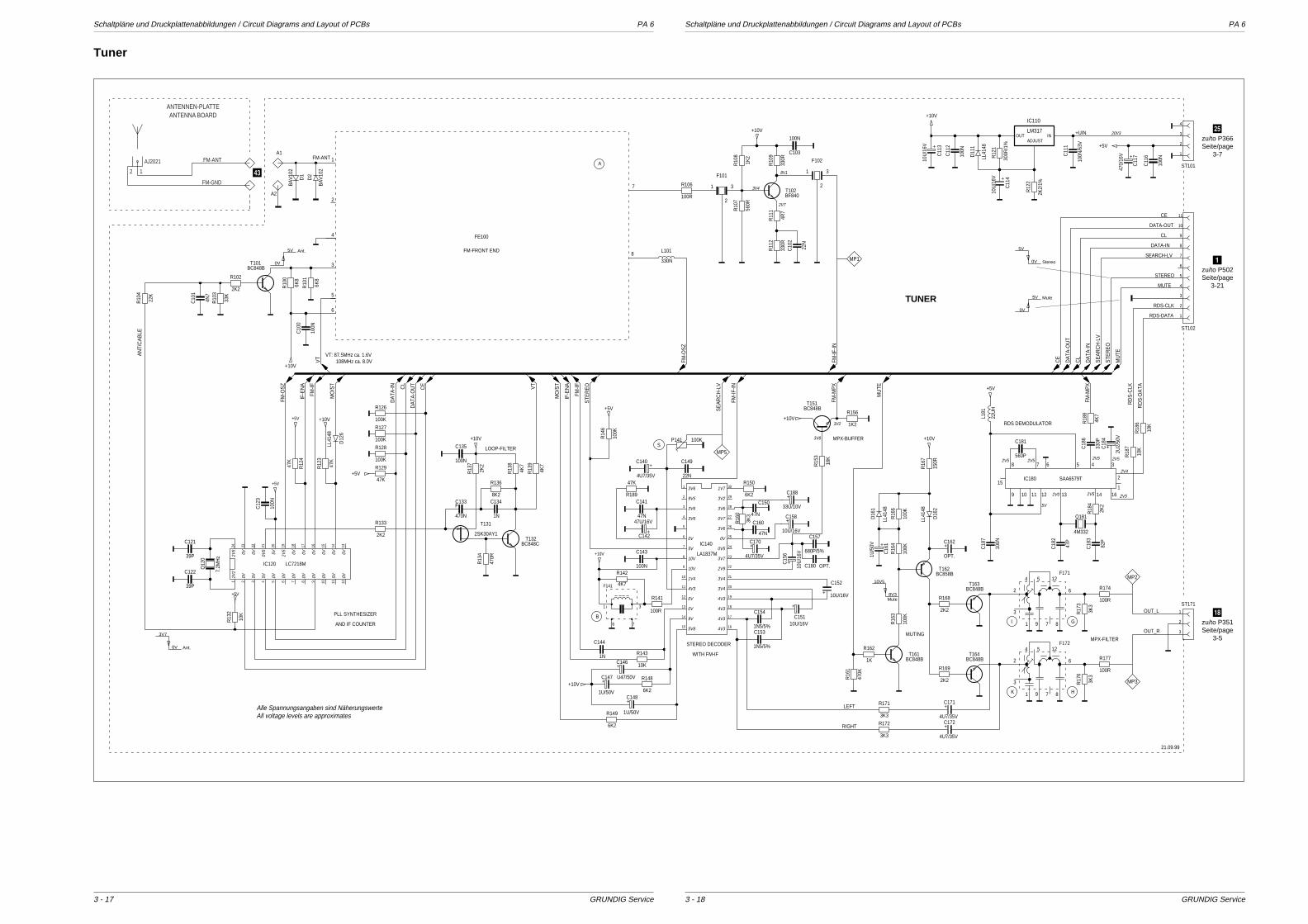
Schaltpläne und Druckplattenabbildungen / Circuit Diagrams and Layout of PCBs PA 6 Schaltpläne und Druckplattenabbildungen / Circuit Diagrams and Layout of PCBs PA 6
GRUNDIG Service GRUNDIG Service
100KP141
R126
R18
8
10K
R18
61K2
R156
S
LL41
48
D16
1
BC848BT161
BC858BT162
100K
R16
6
6K2
R148
SAA6579TIC180
8
6
1 9 7
5 124
2
3
F171
A1
22N
C149
BC848BT101
6K8
R10
1
6K8
R10
02K2
R102
33K
R10
34N
7
C10
1
22K
R10
4
330N
L101
100R
R106
7.2M
Hz
Q12
039P
C121
39P
C122
100N
C12
3
47N
C160
47N
C150
3K3
R16
0
100K
47K
R12
4
100K
R127
100K
R128
47K
R129
10K
R13
2
470R
R13
4
1N
C134
2K2
R133
BC848CT132
2SK30AY1
T131
F
470N
C1338K2
R1362K
2
R13
7
4K7
R13
8
4K7
R13
9
+
33U/10V
C188
LL41
48
D12
6
47K
R12
3
22U
H
L181
BA
V10
2
D2
4M332
Q181
2K2
R18
4
47P
C18
2
+
2U2/
50V
C18
482
P
C18
3
560P
C181
330P
C18
6
4K7
100N
C18
7
10K
R18
7
BA
V10
2
D1
+
4U7/35V
C170
100N
C135
3K3
R17
3
100R
R174
100R
R177
3K3
R17
6
8
6
1 9 7
5 124
2
3
F172
BC848BT163
BC848BT164
2K2
R168
2K2
R169
+
OPT.
C162
100K
R16
3
100K
R16
4
LL41
48
D16
215
0R
R16
7
+
1U/5
0V
C16
1
1K
R162
470K
R16
1
+
4U7/35V
C171
+
4U7/35V
C1723K3
R171
3K3
R172
3
2
1
F101
22N
C10
2
560R
R10
7
1K2
R10
8
330R
R10
9
3
2
1
F102
MP1
4R7
R11
1
330R
R11
2
LA1837M
IC140
100N
C143
+
U47/50V
C146
1N5/5%
C1531N5/5%
C154
+ 10U/16V
C152
+
10U/16VC151
680P/5%
C157
18K
R15
3
+
10U
/16V
C15
6
+
10U/16V
C15847N
C141
+
47U/16V
C142
47K
R189
100K
R14
6
100R
R141
4K7
R142
+
1U/50V
C148
6K2
R149
10K
R1431N
C144
+
1U/50V
C147
BC848BT151
100N
/63V
C11
1
100N
C11
2
ADJUST
LM317OUT IN
IC110
+
470/
16V
C11
7
100N
C11
6
6K2
R150
ST101
OPT.C180
ST171
100N
C103
+
10U
/16V
C11
3
100N
C10
0
LL41
48
D11
1
+
10U
/16V
C11
4
2K2/
1%
R12
2
BF840T102
6
1 3
7
F141
ST102
+
4U7/35V
C140
1
2
4
3
5
6
7
8
FE100
A2
LC7218MIC120
300R
/1%
R12
1
VT
VT
RDS-CLK
RD
S-C
LK
FM-O
SZ
FM-O
SZ
DA
TA-IN
DATA-IN
DA
TA-IN
+UIN
SEARCH-LV
SE
AR
CH
-LV
SE
AR
CH
-LV
LEFT
RIGHT
MO
/ST
MO
/ST
DA
TA-O
UT
DATA-OUT
DA
TA-O
UT
FM-M
PX
FM-M
PX
OUT_R
FM-IF
-IN
FM-IF
-IN
CL
CL
CL
IF-E
NA
IF-E
NA
MUTE
MU
TE
MU
TEAN
T/C
AB
LE
STEREO
STE
RE
O
STE
RE
O
+10V
+10V
+10V
+10V
+10V
+10V
+10V
+10V
+10V
+5V
+5V
+5V
+5V
+5V
+5V
+5V
FM-IF
FM-IF
RDS-DATA
RD
S-D
ATAC
E
CE
CE
OUT_L
FM-ANT
HK
GI
A
B
21.09.99
AND IF COUNTER
PLL SYNTHESIZER
WITH FM-IF
STEREO DECODER
MUTINGMPX-FILTER
RDS DEMODULATOR
MPX-BUFFER
LOOP-FILTER
FM-FRONT END
8 7 6 5 4 3
2
1614139 10 11 121
151
2
3
4
5
6
7
8
9
10
11
12
13
14
15 16
17
18
19
20
21
22
23
24
25
26
27
28
29
30
1
2
3
4
1
2
3
4
5
6
7
8
9
10
11
1 2 3 4 5 6 7 8 9 10 11 12131415161718192021222324
1
2
3
MP5
MP2
MP3
AJ2021
FM-GND
FM-ANT
12
ANTENNEN-PLATTEANTENNA BOARD
TUNER
5V
0V Stereo
5V
0V
Mute
5V
0V
Ant.
3V7
0V Ant.
10V5
8V3Mute
Alle Spannungsangaben sind NäherungswerteAll voltage levels are approximates
2V5
0V 0V 0V5
5V 2V5
0V 0V 0V 0V 0V 0V
2V2
0V 5V 5V 0V 0V 0V 0V 0V 0V 5V 0V
3V6
9V5
3V6
3V6
0V
5V
10V
10V
1V4
4V3
0V
0V
9V
5V8
1V7
3V2
3V6
0V7
3V6
0V
0V5
3V7
2V9
3V4
3V4
4V3
4V3
4V3
4V3
2V4
2V52V5
5V
2V5
2V52V5
2V5
2V0
20V3
VT: 87.5MHz ca. 1.6V 108MHz ca. 8.0V
8V1
2V7
3V4
3V8
3V2
Tuner
3 - 183 - 17
;zu/to P366Seite/page
3-7
1zu/to P502Seite/page
3-21
~zu/to P351Seite/page
3-5
3
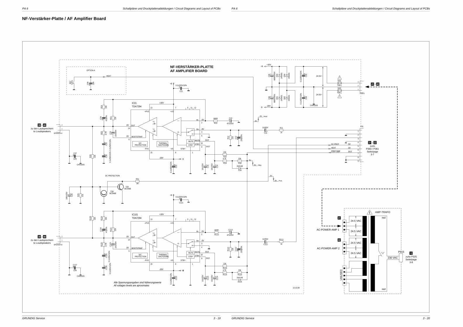
PA 6 Schaltpläne und Druckplattenabbildungen / Circuit Diagrams and Layout of PCBs PA 6 Schaltpläne und Druckplattenabbildungen / Circuit Diagrams and Layout of PCBs
GRUNDIG Service GRUNDIG Service
NF-VERSTÄRKER-PLATTEAF AMPLIFIER BOARD
230 VAC
P915
AMP-TRAFO
red
red
24.5 VAC
24.5 VAC
24.5 VAC
24.5 VAC
!
AC-POWER-AMP 1
AC-POWER-AMP 2
UN
US
ED
5V
0V Prot.
5V
0V Stby
5V
0V
Heat
K
22N
C127
K
22N
C27
F
0.1U
/50V
/10%
C03
85C
THP
01
22k
R28
22k
R12
4
22k
R12
8T4A-L
SI02
4.7R
R12
5
22k
R12
1
680R
R113
D116
1N4148
47k
R29
22k
R1154.7k
R114
TRAFO
1
2
3
+
1U/50V
C111
F
0.1U
/50V
/10%
C04
+
22U
/50V
C12
3
1N54
01
D04
1N54
01
D01
K
220p
/5%
C11
2
22k
R24
+
47U/25V
C113
BOOTSTRAP
OUT
+VS+PVS
-PVS -VS STBY-
IN+
IN-
STBY
MUTE
SHUTDOWNTHERMAL
PROTECTIONS/C
STBY
MUTE
22k
R11
2
F
0.1U
/50V
/10%
C12
5
33k
R116
K 47p/
5%
C24
F
0.1U
/50V
/10%
C12
2F
0.1U
/50V
/10%
C22
F0.1U/50V/10%
C121
F
0.1U
/50V
/10%
C25
+
10U
/25V
C11
4
F0.1U/50V/10%
C21
+
10U
/25V
C11
5
4.7RR25
K
220p
/5%
C12
1k
R111
22k
R21 680R
R13
1N54
01
D02
22k
R154.7k
R14
+
1U/50V
C11
+
22U
/50V
C23
F
0.1U
/50V
/10%
C12
6
+
47U/25V
C13
BOOTSTRAP
OUT
+VS+PVS
-PVS -VS STBY-
IN+
IN-
STBY
MUTE
SHUTDOWNTHERMAL
PROTECTIONS/C
STBY
MUTE
TDA7294IC01
22k
R12
K 10N
C09
K 47p/
5%
C12
4
F
0.1U
/50V
/10%
C26
33k
R16
D16
1N4148
+
6800
U/5
0V
C06
+
6800
U/5
0V
C05
+
10U
/25V
C14
0R
R31
1N54
01
D03
+
10U
/25V
C15
SPEAKER-B
1
2
9
8
7
6
5
4
3
2
1
P01
T4A-L
SI01
1k
R11
+
100U
/25V
C29
BC546BT28
BC546BT29
SPEAKER-A
1
2
+B
+B
+B
-B
-B
-B
-B
HEAT
HEAT
CHASSIS
CHASSIS
CHASSIS
DC-PROT
13.10.99
STBY-AMP
OPTION-A
DC PROTECTION
13 7 5 11 12
2
3
4
10
9
1815
6
14
13 7 5 11 12
2
3
4
10
9
1815
6
14
TDA7294IC101
-30V
+30V
+30V
-30V
0V
0V
0V
0V
5V3
5V3
5V3
5V3
+30V
-30V
0V
0V
0V
0V
24.5V~
24.5V~
Alle Spannungsangaben sind NäherungswerteAll voltages levels are aproximates
5V3
0V
5V
3 - 203 - 19
NF-Verstärker-Platte / AF Amplifier Board
- / .zu/to
P360 / P361Seite/page
3-7
#zu/to P325Seite/page
3-8
V / 0zu den Lautsprechern
to Loudspeakers
V / 0zu den Lautsprechern
to Loudspeakers
1
2
1 / 2
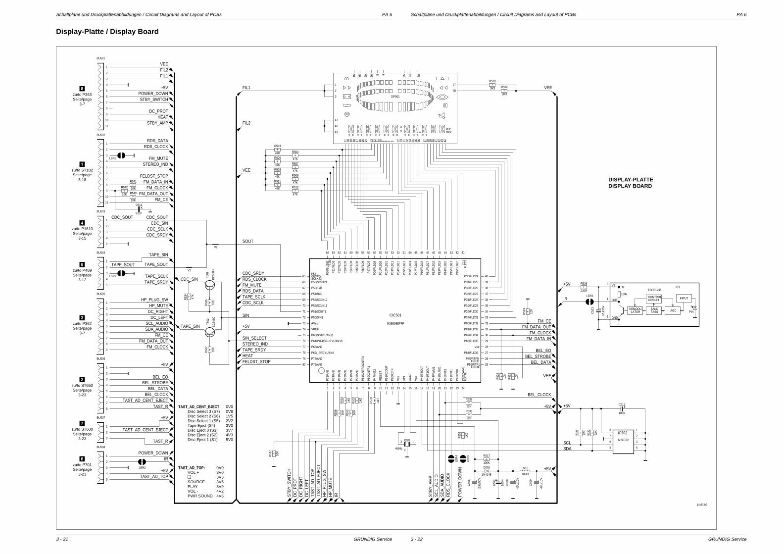
Schaltpläne und Druckplattenabbildungen / Circuit Diagrams and Layout of PCBs PA 6 Schaltpläne und Druckplattenabbildungen / Circuit Diagrams and Layout of PCBs PA 6
GRUNDIG Service GRUNDIG Service
5
4
3
2
1
BU504
5
4
3
2
1
BU508
11
10
9
8
7
6
5
4
3
2
1
BU502
9
8
7
6
5
4
3
2
1
BU505
8
7
6
5
4
3
2
1
BU506
10K
R52
8
5
4
3
2
1
BU503
3
2
1
BU507
4526294546
REC
kHzMHz
1
2
3
6789101112131415161718192021 22 23
2425
27
28
30
31 32 33 34 35 36 37 38 39 40 41 42 43 44
47
48
49
DP501
FLD38P86/RTP1
FLD37P85/RTP0
P84/FLD36
Vee
P83/FLD35
P82/FLD34
P81/FLD33
P80/FLD32
P37/FLD31
P36/FLD30
P35/FLD29
P34/FLD28
P33/FLD27
P32/FLD26
P31/FLD25
P30/FLD24
FLD
23P17
P16
/FLD
22
P15
/FLD
21
P14
/FLD
20
P13
/FLD
19
P12
/FLD
18
P11
/FLD
17
P10
/FLD
16
P07
/FLD
15
P06
/FLD
14
P05
/FLD
13
P04
/FLD
12
P03
/FLD
11
P02
/FLD
10
P01
/FLD
09
P00
/FLD
08
P27
/FLD
7
P26
/FLD
6
P25
/FLD
5
P24
/FLD
4
P23
/FLD
3
P22
/FLD
2
P21
/FLD
1FL
D0
P20
/BU
Z02
P57/SRDY2SCLK22P56/SCLK21
P55/TxD
P54/RxD
P53/SCLK12
P52/SCLK11
P51/SOUT1
P50/SIN1
AVss
VREF
P65/SSTB1/AN11
P64/INT4/SBUSY1/AN10
P63/AN9
P62/_SRDY1/AN8
P77/AN7
P76/AN6
FLD
39P
87/P
WM
0
P40
/INT0
P41
/INT1
P42
/INT3
P43
/BU
Z01
P44
/PW
M1
P45
/T1O
UT
P46
/T3O
UT
Vcc
XO
UT
XIN
Vss
P90
/XC
IN
P91
/XC
OU
T
/RE
SE
T
P47
/INT2
P60
/CN
TR1
P61
/CN
TR0/
CN
TR2
P70
/AN
0
P71
/AN
1
P72
/AN
2
P73
/AN
3
P74
/AN
4
P75
/AN
5
65
66
67
68
69
70
71
72
73
74
75
76
77
78
79
80
414243444546474849505152535455565758596061626364
25
26
27
28
29
30
31
32
33
34
35
36
37
38
39
40
10 11 12 13 14 15 16 17 18 19 20 21 22 23 241 2 3 4 5 6 7 8 9
CIC501
47K
R504
47K
R506
47K
R507
47K
R509
47K
R503
47K
R508
47K
R511
47K
R512
3K3
R501
3K3
R502
100K
R51710K
R52
7
220R
R526
BC
548C
T502
3
2
1Q502
4MHz
F
100N
C50
7+
2U2/
50V
C50
6
BC
558B
T501
+
22U
/35V
C51
3
+
47U
/10V
C50
8
10UH
L501
+
47U
/10V
C50
9
1N4148
D501
10K
R541
LBR7
F
100N
C512
10K
R53
6
10K
R53
7
47K
R53
4
LBR
4
10K
R542
LBR
5
5
6
7
8
4
3
2
1
M24C32
IC50222K
R52
2
22K
R52
1
LBR2
LBR1
PIN
100k
VS
GND
OUT
LATORDEMODU-
CIRCUITCONTROL
PASSBAND
INPUT
AGC
3
2
1
TSOP1236IR1
10K
R52
9
10K
R53
2
22K
R539
4K7
R53
3
1K0
R55
2
1K0
R55
4
1K0
R55
3
1K0
R55
1
1K0
R55
6
V2
V1
10K
R543
11
10
9
8
7
6
5
4
3
2
1
BU501
22K
R538
LBR6
DC
_PR
OT
DC_PROT
FIL1
FIL1
SCL
TAPE_SCLK
TAPE_SCLK
HP
_PLU
G_S
W
HP_PLUG_SW
TAPE_SRDY
TAPE_SRDY
STBY_SWITCH
STB
Y_S
WIT
CH
FELDST_STOP
FELDST_STOP
PO
WE
R_D
OW
N
POWER_DOWN
POWER_DOWN
FM_MUTE
FM_MUTE
FM_CLOCK
FM_CLOCK
FM_CLOCK
TAPE_SIN
TAPE_SIN
HEAT
HEAT
HP
_MU
TE
HP_MUTE
FM_DATA_IN
FM_DATA_IN
+5V
+5V
+5V
+5V
+5V
+5V
+5V
+5V
+5V
TAPE_SOUTTAPE_SOUT
STB
Y_A
MP
STBY_AMP
BEL_DATA
BEL_DATA
IR
IR
IR
FM_DATA_OUT
FM_DATA_OUT
FM_DATA_OUT
CDC_SOUTCDC_SOUT
DC
_RIG
HT
DC_RIGHTTA
ST_
AD
_TO
P
TAST_AD_TOP
SDA_AUDIO
SD
A_A
UD
IO
STEREO_IND
STEREO_IND
BEL_EO
BEL_EO
BEL_STROBE
BEL_STROBE
BEL_CLOCKBEL_CLOCK
TAST_R
TAST_R
DC
_LE
FT
DC_LEFTTA
ST_
AD
_EJE
CT
TAST_AD_CENT_EJECT
TAST_AD_CENT_EJECT
RDS_DATA
RDS_DATA
FIL2
FIL2
SDA
VEE
VEE
VEE
VEE
SOUT
FM_CE
FM_CE
FM_CE
CDC_SIN
CDC_SIN
CDC_SCLK
CDC_SCLK
RD
S_C
LOC
K
RDS_CLOCK
RDS_CLOCK
SCL_AUDIO
SC
L_A
UD
IO
CDC_SRDY
CDC_SRDY
SIN
SIN_SELECT
14.03.00
M38B59EFFP
DISPLAY-PLATTEDISPLAY BOARD
K
220P
C511
TAST_AD_TOP: 0V0VOL + 3V09 3V3SOURCE 3V6PLAY 3V9VOL - 4V2PWR SOUND 4V6
TAST_AD_CENT_EJECT: 0V0Disc Select 3 (S7) 0V8Disc Select 2 (S6) 1V5Disc Select 1 (S5) 2V2Tape Eject (S4) 3V0Disc Eject 3 (S3) 3V7Disc Eject 2 (S2) 4V3Disc Eject 1 (S1) 5V0
3 - 223 - 21
Display-Platte / Display Board
8zu/to P363Seite/page
3-7
1zu/to ST102Seite/page
3-18
4zu/to P1610Seite/page
3-15
5zu/to P409Seite/page
3-12
3zu/to P362Seite/page
3-7
2zu/to ST650Seite/page
3-23
7zu/to ST600Seite/page
3-23
6zu/to P701Seite/page
3-23
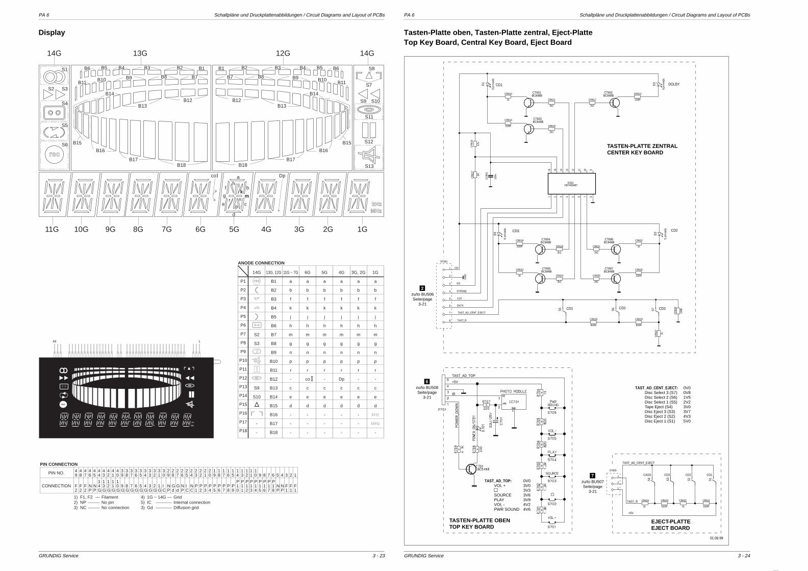
PA 6 Schaltpläne und Druckplattenabbildungen / Circuit Diagrams and Layout of PCBs PA 6 Schaltpläne und Druckplattenabbildungen / Circuit Diagrams and Layout of PCBs
GRUNDIG Service GRUNDIG Service 3 - 243 - 23
B15
B16
B17B18
B12B13
B14
B11B10 B9 B8 B7
B1B2B3B4B5B6
B18B17
B16
B15
B13B12
B7 B8 B9 B10B11
B6B5B4B3B2B1
rec
S1
S3S2
S4
S5
S6
S13
S12
S11
S10S9
S7
S8
kHzMHz
co a
b
c
d
e
f
g
h jkk
mmn
pr
Dp
14G 13G 12G 14G
11G 10G 9G 8G 7G 6G 5G 4G 3G 2G 1G
B14
Display
49 1
MHz
kHz
rec
49
48
47
46
45
44
43
42
41
40
39
38
37
36
35
34
33
32
31
30
29
28
27
26
25
24
23
22
21
20
19
18
17
16
15
14
13
12
F2
F2
F2
NP
NP
14G
13G
12G
11G
10G
9G
8G
7G
6G
5G
4G
3G
2G
1G
IC
NP
Gd
Gd
NP
IC
NC
P1
P2
P3
P4
P5
P6
P7
P8
P9
P10
P11
P12
PIN NO.
CONNECTION
PIN CONNECTION
11
P13
10
P14
9
P15
8
P16
7
P17
6
P18
5
NP
4
NP
3
F1
2
F1
1
F1
1) F1, F22) NP 3) NC
FilamentNo pinNo connection
-------------------
4) 1G ~ 14G5) IC3) Gd
GridInternal connectionDiffusion grid
-------------------------
P1
P2
P3
P4
P5
P6
P7
P8
P9
P10
P11
P12
P13
P14
P15
P16
P17
P18
14G
S2
S3
S9
S10
-
-
13G, 12G
B1
B2
B3
B4
B5
B6
B7
B8
B9
B10
B11
B12
B13
B14
B15
B16
B17
B18
11G ~ 7G
a
b
f
k
j
h
m
g
n
p
r
-
c
e
d
-
-
-
6G
a
b
f
k
j
h
m
g
n
p
r
co
c
e
d
-
-
-
5G
a
b
f
k
j
h
m
g
n
p
r
-
c
e
d
-
-
-
4G
a
b
f
k
j
h
m
g
n
p
r
Dp
c
e
d
-
-
-
3G, 2G
a
b
f
k
j
h
m
g
n
p
r
-
c
e
d
-
-
-
1G
a
b
f
k
j
h
m
g
n
p
r
-
c
e
d
kHz
MHz
-
ANODE CONNECTION
rec
PO
WE
R_D
OW
N
+5V
IR
TAST_AD_TOP
2k2
CR612
8
0R
CR
617
820R
CR629
D4
TLH
Y44
05
S6
S5
S7
BC848BCT606
1k
CR622
BC848BCT607
330R
CR613
2k2
CR624 330R
CR626
330R
CR619
100n
CC
601
1k
CR623
2k2
CR620
2k2
CR621
2k2
CR625
820R
CR628
BC848BCT605
BC848BCT604
16 15 14 13 12 11 10 987654321
IC601HEF4094BT
1k
CR
627
2
D3
TLH
Y44
05
3
4
5
6
7
47k
CR
616
BC848BCT601
BC848BCT603
2k2
CR611
330R
CR614
1k
CR610
2k2
CR615
D1
TLH
Y44
05
BC848BCT602
D2
TLH
Y44
05
1
100K
CR
630
STROBE
DATA
TAST_R
CLK
+5V
EO
GN
D
TAST_AD_CENT_EJECT
01.06.99
CD3CD2CD1
CD2CD3
DOLBYCD1
ST650
1k
CR634
S2
S3
S4
820R
CR633
1k
CR632
820R
CR631
1
2
3
S1
+5V
TAST_R
TAST_AD_CENT_EJECT
CD1CD2CD3CASSST600
TASTEN-PLATTE ZENTRALCENTER KEY BOARD
TASTEN-PLATTE OBENTOP KEY BOARD
EJECT-PLATTEEJECT BOARD
TAST_AD_TOP: 0V0VOL + 3V09 3V3SOURCE 3V6PLAY 3V9VOL - 4V2PWR SOUND 4V6
TAST_AD_CENT_EJECT: 0V0Disc Select 3 (S7) 0V8Disc Select 2 (S6) 1V5Disc Select 1 (S5) 2V2Tape Eject (S4) 3V0Disc Eject 3 (S3) 3V7Disc Eject 2 (S2) 4V3Disc Eject 1 (S1) 5V0
Tasten-Platte oben, Tasten-Platte zentral, Eject-PlatteTop Key Board, Central Key Board, Eject Board
7zu/to BU507Seite/page
3-21
6zu/to BU508Seite/page
3-21
2zu/to BU506Seite/page
3-21
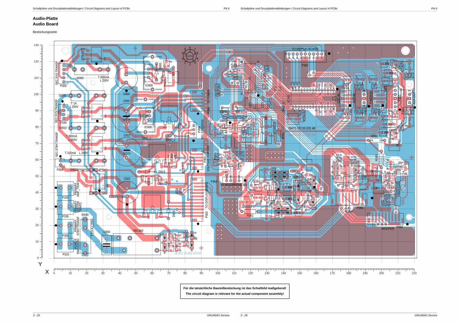
Schaltpläne und Druckplattenabbildungen / Circuit Diagrams and Layout of PCBs PA 6 Schaltpläne und Druckplattenabbildungen / Circuit Diagrams and Layout of PCBs PA 6
GRUNDIG Service GRUNDIG Service
~~ -
+
BR
910
~~ -
+
BR
930
~~ -
+
BR
920
~~ -
+
BR
900
T371
T920
T700
T370
T912
T202
T911
T203
IC370IC360
IC70
0
IC90
4IC
902
IC90
3IC
905
IC920
IC910
IC931Y
T913
T702
+-
C29
3
+-
C29
2
C25
4
C29
5
C364
C29
4
C93
5Y
C365
C20
0C
201
C703C704
C707
C27
9
C93
0
C285
C284
C283
C28
0
C281
C282
C27
0
C274
C273
C91
3
C91
4
C91
1C
910
C93
6
C286
C25
5
C22
0
C22
1
C23
0C
231
C21
0C
211
C92
3
C92
4
C921 C920
C241
C240
C70
2
C70
5
C93
4
C93
1C
901
C90
0
C93
8C
949
C94
4
C93
9
C94
2
C948
C94
1
C94
0
C94
3
R910
R91
1
R25
1
R272
R271
R27
0
R274
R25
0
R273
R70
8
R71
0
R70
7
R70
4
R706
R702
R703R705
C706
R20
1
R37
3
R368
R367
R365
R290
R366
R37
1R36
3
R291
R20
0
R25
4R
255
R25
3R
252
R22
0
R22
1
R23
0R
231
R21
0R
211
R92
2
R923
R925
R921
R369
R37
0
R920
R24
2
R24
1
R24
3
R240
R37
2
R364
R36
2
R374
R377
R709
R711
R713
R379
R378
R712
R376
R375
R91
2R
913
R91
5R
914
R901
R90
2
R900
R24
4
R385
R38
4
R351
R352
R977
R97
9
R97
2
R96
7
R96
9
R38
2
R971
R975
R963R96
5
R381R98
4R98
2
R96
4
R97
4
R71
4
R717
C712
R98
1
R71
5
R98
0
R719
R716
R718
R97
8
R72
0
R97
6
R20
7
R98
3R
257
R20
6
R25
6
C710
R96
8
R93
7
-+C999
11415
28
IC27
0
T914
-+
C27
2
-+
C27
1
-+C252
-+
C70
1-
+C
700
- +C361
-+
C36
0
-+
C90
3
- +C242
-+
C35
2
-+
C35
1
-+C385
-+
C71
3
-+
C70
9
-+C350
-+
C71
1
-+
C70
8
-+C251
-+C250
- +C276
-+
C27
8
-+
C27
7
-+C291
- +C275
-+C366
-+C367
-+C290
-+
C92
6
- +C370
- +C371
-+
C91
5
-+
C92
8
-+
C92
7
-+C223
-+C222
-+C229
-+C228
- +C362
- +C363
-+C202
-+C203
-+C212
-+C213
14
14
D91
2
D37
3
D367 D366
D365D364
D361
D363
D360
D362
D37
1
D920
D921
D92
2
D37
0
D37
2
D91
0D
911
D90
1
111
C947C946
C94
5
T701
R905
R92
4
R93
9Y
51
P35
2
R360R70
1
R361
R38
3
3016
15 1
IC24
0
31
P35
4
31
P35
3
D90
0
D92
3D913
P35
0
P35
1
P361
P360
SI910
SI920
SI930
SI940
SI900
+
C912
+
C932
1
6
32
54 8
7
051
423
9
P36
6P
365
14
P364
P369
P36
3
P300
REL900
9 1
P362
P330
32
1
IC930
32
1
IC900
C950
21
P315
21
P325
21
P335
21
P305
C922
C902
31
P36
8 59472-322.00 (03) 4B
GN
D_3
GND_2GND_1
T 2,
5 A
L 25
0V
HT/MT
WOOFER
BE
L-S
TRE
IFE
N
STB
Y-TR
AN
SF
SW
ITC
H-B
DP
OW
ER
TRA
FOS
YS
TEM
AM
P_T
RA
FOP
RIM
AR
YP
RIM
AR
YP
RIM
AR
Y
SE
C.S
TBY.
TRA
NS
FS
EC
.SY
S.T
RA
NS
FS
EC
.SY
S.T
RA
NS
F
TAP
E
AU
X-O
UT
TUN
ER
-IN
AU
X-IN
CD
C-IN
TO DISPLAY-BOARD
TO T
UN
ER
VO
LTG
AE
FO
R C
DC
TO D
ISP
LAY-
BO
AR
D
TO HEADPHONE-BD
T 315mA
T 500mA
L 250V
L 250V
T 800mA
L 250V T 1A
L 250V
1501401301201101009080706050403020100 160 170 180 190 200 210 220
130
120
110
100
90
80
70
60
50
40
30
20
10
0
XY
3 - 263 - 25
Audio-PlatteAudio Board
Für die tatsächliche Bauteilbestückung ist das Schaltbild maßgebend!
The circuit diagram is relevant for the actual component assembly!
Bestückungsseite

PA 6 Schaltpläne und Druckplattenabbildungen / Circuit Diagrams and Layout of PCBs PA 6 Schaltpläne und Druckplattenabbildungen / Circuit Diagrams and Layout of PCBs
GRUNDIG Service GRUNDIG Service
Bauteil-Koordinaten Audio-PlatteCoordinates of Components Audio Board
Pos.-Nr./ Koordinaten/Pos. No. Coordinates
X Y
Pos.-Nr./ Koordinaten/Pos. No. Coordinates
X Y
Pos.-Nr./ Koordinaten/Pos. No. Coordinates
X Y
Pos.-Nr./ Koordinaten/Pos. No. Coordinates
X Y
3 - 283 - 27
AUX-In/Out-PlatteAUX In/Out Board
Netzschalter-PlatteMains Switch Board
Detektor-PlatteDectector Board
CD640ST601
CR
640
1A K
BeleuchtungsstreifenIllumination Board
1
ST660
2
43
ST661
CC603
CC601
CC602
Kopfhörer-PlatteHeadphone Board
Eject-PlatteEject Board
S1S4 S3 S23 2 1ST600 CR631CR632CR633CR634
BR900 26 124BR910 27 69BR920 28 47BR930 27 89
C200 178 90C201 178 105C202 178 86C203 179 109C210 195 90
C211 195 105C212 195 86C213 195 109C220 209 87C221 207 108
C222 203 87C223 203 108C228 187 86C229 187 109C230 217 89
C231 217 112C240 152 88C241 149 90C242 146 85C250 204 82
C251 204 113C252 208 69C254 211 79C255 211 119C270 132 93
C271 128 95C272 120 95C273 100 100C274 100 104C275 114 90
C276 105 90C277 129 110C278 111 119C279 130 105C280 128 105
C281 111 111C282 111 110C283 111 115C284 111 113C285 130 117
C286 130 115C290 201 77C291 202 119C292 217 83C293 217 118
C294 187 90C295 187 105C350 118 34C351 129 51C352 130 28
C360 195 53C361 198 43C362 125 43C363 125 37C364 135 48
C365 134 33C366 142 43C367 142 36C370 150 49C371 150 28
C385 189 45C700 130 83C701 130 73C702 116 79C703 113 86
C704 108 86C705 105 81C706 108 57C707 113 57C708 122 79
C709 114 71C710 113 63C711 105 71C712 108 63C713 99 79
C900 18 123C901 18 127C902 45 110
C903 73 111C910 18 71
C911 18 68C912 45 65C913 55 57C914 68 57C915 72 61
C920 20 54C921 16 54C922 45 40C923 55 26C924 66 26
C926 58 48C927 215 57C928 206 57C930 18 91C931 18 87
C932 45 86C934 55 87C935Y 77 81C936 55 83C938 205 33
C939 186 58C940 173 60C941 171 57C942 171 53C943 186 54
C944 184 59C945 202 49C946 206 43C947 210 43C948 202 33
C949 205 37C950 32 8C999 154 58
D360 141 52D361 136 52D362 136 50D363 141 50D364 138 30
D365 143 30D366 143 28D367 138 28D370 149 44D371 149 35
D372 159 48D373 159 34D900 63 114D901 69 119D910 84 14
D911 84 8D912 68 7D913 57 53D920 24 40D921 24 54
D922 68 13D923 70 29
IC240 159 98IC270 120 110IC360 134 40IC370 154 40IC700 111 79
IC900 58 113IC902 210 50IC903 179 54IC904 210 35IC905 179 47
IC910 63 63IC920 61 32IC930 59 87IC931Y 71 87
P300 6 113P305 7 19P315 7 8P325 7 42P330 6 89
P335 7 31P350 179 98P351 199 98P352 207 98P353 188 98
P354 216 98P360 203 24P361 180 36P362 154 123P363 88 36
P364 109 48P365 88 61P366 88 96P368 85 78P369 4 58
R200 179 90R201 179 105R206 189 90R207 189 105R210 197 90
R211 197 105R220 207 87R221 209 108R230 219 89R231 219 112
R240 152 90R241 150 106R242 148 106R243 146 106R244 153 85
R250 213 83R251 213 116R252 215 89R253 215 112R254 213 79
R255 213 119R256 184 90R257 184 105R270 132 97R271 100 102
R272 100 106R273 107 111R274 107 113R290 210 116R291 208 78
R351 124 47R352 125 33R360 197 72R361 120 28R362 129 43
R363 129 37R364 134 54R365 136 25R366 138 48R367 135 46
R368 134 35R369 137 33R370 138 44R371 138 35R372 147 43
R373 147 37R374 159 42R375 159 38R376 156 46R377 159 30
R378 153 46R379 151 32R381 199 48R382 200 51R383 200 60
R384 189 53R385 189 50R701 138 75R702 117 76R703 117 86
R704 117 79R705 105 86R706 105 78R707 104 81R708 116 64
R709 100 61R710 106 64R711 100 63R712 104 58R713 104 59
R714 135 78R715 135 81
R716 117 84R717 105 84R718 113 65
R719 108 65R720 106 52R900 67 108R901 67 110R902 67 113
R905 73 57R910 72 14R911 75 9R912 75 13R913 75 6
R914 82 14R915 82 9R920 30 40R921 30 54R922 54 49
R923 63 50R924 81 54R925 63 48R937 78 41R939Y 75 41
R963 210 46R964 182 59R965 205 46R967 209 55R968 184 56
R969 205 51R971 210 41R972 211 55R974 171 50R975 210 39
R976 186 51R977 202 35R978 175 60R979 203 37R980 173 57
R981 173 53R982 173 50R983 184 52R984 184 48
REL900 51 9
SI900 23 115SI910 21 80SI920 21 59SI930 21 99SI940 19 13
T202 208 75T203 208 119T370 155 49T371 155 33T700 114 59
T701 108 59T702 100 58T911 79 14T912 79 9T913 72 11
T914 72 6T916Y 78 49T917Y 74 49T920 67 47
Für die tatsächliche Bauteilbestückung ist das Schaltbild maßgebend!
The circuit diagram is relevant for the actual component assembly!
Bestückungsseite
Bestückungsseite
Lötseite
Bestückungsseite Bestückungsseite Bestückungsseite
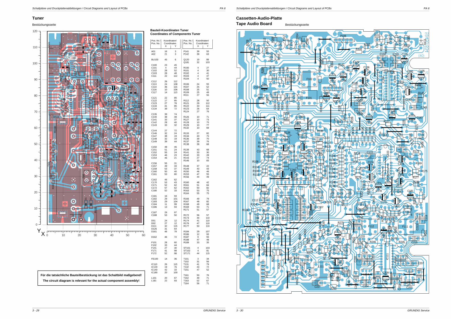
Schaltpläne und Druckplattenabbildungen / Circuit Diagrams and Layout of PCBs PA 6 Schaltpläne und Druckplattenabbildungen / Circuit Diagrams and Layout of PCBs PA 6
GRUNDIG Service GRUNDIG Service
C184
C135
L101
C103
P14
2F1
71
IC18
0
T102
D16
1
C10
0
DST131
C13
3
F101
2 3 1IC110
F141
FE10
0
C113
R16
6Q12
0
R148
-+
C11
7
C14
9
R10
1R
100
R10
2R
103
C10
1R
104
R10
6
C121C122
C16
0C
150
R160
R12
6
R124
R12
7R
128
R129
D111
R13
2
Q18
1
R13
4
C134
R133
R136
R137
R138R139
R123
R18
4C
182
C18
3
C18
1C18
6
R188
C18
7
R18
6
R18
7
D2
D1
A1
R173R174 R177
R176
R168
R16
9
R163R164
R16
7R
162 R161
R171
R17
2
C102R10
7
R10
8
R109
R111
R112
C14
3
C154
C153
C15
7R
153
C14
1
R18
9
R146
R14
1
R142
R14
9
R143
C144
IC140
R15
6
C112
C11
6
R15
0
D126
T162
D16
2
T101
R122
T132
T163
T164
T151
F172
P14
1
L181
ST1
71
-+
C18
8
-+
C16
2
-+
C14
2
C16
1
C17
1
C17
2
C14
6
C152C151
C15
6C
158
C14
8
C14
7
F102
A2
ST1
01
R121
ST102
IC12
0
C123
C17
0
C114
C14
0
C18
0
T161
C11
1
BU
100
5947
2-31
0.00
(02)
4BR
DS
/FM
-Tun
er
6050403020100
120
110
100
90
80
70
60
50
40
30
20
10
0
XY
R149
R108
CET192
C119
+
C402
R136
1 9IC101
R130
CE
T153
L114
R145
R129
D10
2
R350
R125
R17
1
R10
9
R105
R111
R113
R26
8
R123
R117
R121
R340
R10
1
R103
R14
1
R133
R142
R104
R102
R15
4
R122
R118
R114 R116
R112
R106
R13
2
R126
R124
R134
R13
8
R127R128
22
11 12
1
IC10
3+
C403
R146
R20
1
R198
R202
R19
7
R204
R19
5
R18
9
R196
R19
1
R194
R192
R19
3
R18
3
R188
R18
5
R186
R184
R18
7
R21
3
R20
6
R20
5
R20
7
R34
1
R177
R179
R173
R175
R351
R20
8
R20
9
R178
R22
2
R176
R174
R181
R21
5R24
7
R22
9
R21
8
R24
8
R21
6
R27
6
R25
4R
217
R272
R26
9
R26
5
R27
3
R25
2
R274
R271
R26
6R
267
R277
R25
3
R26
1
R26
2
R263
R243
R24
1R24
9
R24
4
R11
9
R110
R303
R30
7 R31
1
R30
2
R30
5
R31
3R30
9
R315
R316
R31
4
R30
6
R31
2
R30
8
D11
1
R28
7
R29
4
R28
5
R281
R29
1
R28
3
R29
3
R28
4
R29
2
R28
6R
288
R26
4
D10
3
D10
1
D11
2
R15
6
R13
1
R28
2
R30
4
C ET190
C E
T103
C ET101
CET109
CE T1
11
CET102
CET104
CE
T105
CET1
28
CET1
27
CE T1
55
CE
T157
C ET163
CET151
CE
T161 C
E T158
CE
T154
C ET164
CE T1
73
CE
T156
CET125
CET162
CE
T126
CE
T108
CE T1
77 CE T1
75
CE T1
71
CE T1
74
CE T1
76
CE T1
78C
E T172
C118
C113
C11
1
C101C103
C105
C114
C127
C133
C123C124
C134
C128
C106C112
C110
C104C102
F111
C143
C145
C146
C144
+C107
C11
7
C171
C21
9
C238
C172
C22
5
C227
C22
3
C22
4C203
C21
1 C21
7
C215
C205
C21
3
C207
C204
C208
C21
4
C20
6
C216
C20
2
C21
8
C21
2C
247C24
8
C24
3
C24
1C
242
C24
4
C25
5
C22
1
C20
1
+
C109
+C121
+
C125
+
C131
+
C132
+
C126
+
C122
+
C116
+C108
+
C149
+
C136
+
C260
+
C135
+
C147
R143R151
+
C179
+
C228
+
C173
+
C148
+
C175
+
C174
+
C176
+
C178
+
C177
+
C181
+ C22
6
+
C222
+
C209
+
C246
+
C249
+
C245+C141
R135
R169R182
R245R246
R30
1
R15
5
R17
2
1
P10
5-1
1 P10
5-2
+C138
R107
L113
CET1
07
+C142
22
11 12
1
IC10
2
R24
2
R28
9
+ C115
F102
F101
L111
R22
1
R137
+C200
C ET106
18 9
16
IC10
4
18109
1
IC11
1
F112
R31
0
R25
1
R275
CET1
31
R115
1
P10
11
P105
1
1
P10
3
P10
4
1P102
1
P106
Cassetten-Audio-PlatteTape Audio Board
3 - 303 - 29
Bauteil-Koordinaten TunerCoordinates of Components Tuner
Pos.-Nr./ Koordinaten/Pos. No. Coordinates
X Y
A01 16 3A02 21 3
BU100 45 6
C100 23 45C101 4 44C102 28 52C103 28 48C111 22 112
C112 26 112C113 24 108C114 36 115C116 10 106C117 14 113
C121 22 85C122 17 85C123 27 78C133 41 85C134 39 72
C135 39 74C140 38 48C141 33 37C142 28 40C143 33 32
C144 27 72C146 32 24C147 38 19C148 32 19C149 39 44
C150 48 46C151 51 24C152 55 24C153 46 23C154 46 21
C156 55 31C157 49 33C158 53 37C160 50 40C161 53 80
C162 46 62C170 53 43C171 52 62C172 57 62C180 52 33
C181 16 93C182 29 101C183 29 104C184 11 99C186 13 93
C187 29 97C188 53 50
D01 24 12D02 27 12D111 32 115D126 31 64D161 46 78
D162 46 72
F101 28 60F102 33 44F141 27 30F171 41 98F172 52 98
FE100 14 36
IC110 26 115IC120 19 76IC140 42 33IC180 20 100
L101 20 67L181 22 93
Pos.-Nr./ Koordinaten/Pos. No. Coordinates
X Y
P141 39 55P142 39 63
Q120 19 89Q181 32 103
R100 4 27R101 4 30R102 4 41R103 4 47R104 4 50
R106 24 55R107 25 52R108 25 51R109 25 49R111 27 55
R112 28 50R121 29 112R122 33 111R123 26 64R124 27 76
R126 10 71R127 10 73R128 10 75R129 10 77R132 10 69
R133 27 82R134 43 75R136 39 70R137 39 76R138 39 68
R139 43 68R141 33 30R142 33 28R143 27 74R146 10 83
R148 37 22R149 43 43R150 46 46R153 47 55R156 44 49
R160 48 42R161 51 84R162 50 82R163 53 75R164 55 75
R166 49 79R167 48 82R168 49 68R169 53 71R171 51 57
R172 56 57R173 44 110R174 41 110R176 47 110R177 50 110
R184 29 107R186 12 93R187 9 93R188 47 48R189 33 35
ST101 4 103ST102 4 81ST171 44 115
T101 3 34T102 31 56T131 41 79T132 43 72T151 47 52
T161 50 76T162 49 71T163 52 67T164 56 71
Tuner
Für die tatsächliche Bauteilbestückung ist das Schaltbild maßgebend!
The circuit diagram is relevant for the actual component assembly!
Bestückungsseite Bestückungsseite
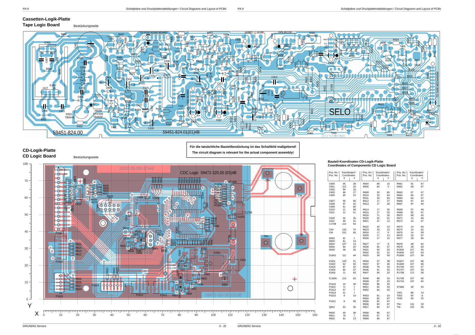
PA 6 Schaltpläne und Druckplattenabbildungen / Circuit Diagrams and Layout of PCBs PA 6 Schaltpläne und Druckplattenabbildungen / Circuit Diagrams and Layout of PCBs
GRUNDIG Service GRUNDIG Service
R45
1
R45
3
R48
5
R44
9
R454
B42
0
R45
6
R452
R41
9
R45
7
R48
3
R41
8
R41
7
R474
R402
R40
1
R40
4
R420
B41
4
R405
R41
6
R41
4 R424
R42
1
B41
7 R42
7 R41
5
R47
7
R422
R425R43
0
R47
9
R47
8
R463
R48
1
R444 R44
8
R44
6
R43
3
R488
R489
R47
6
R465
R48
6
R464
R461
R45
9
R458
R47
5
R472
R471
R46
9
R473
R46
2
B42
2
B41
0
B480
D407
OUT INIC402
B42
1
1
P409
1
P40
6
C40
1
1
IC40
3
R40
6
SI501T800mA
E B
T423
IC405
C E
T415
1P403
C42
7
D41
3
C433 C411
B450
C431
R44
7
R48
4R45
5
R403
C429
C40
9
C434C404
C41
2
D41
2
B403
D409
D414
D415
D42
4
D417
D403
D40
2
D427
D426
D421
D41
8
D42
2
D41
9
D428
B407
F401
C42
8
C426
C425
B425
R42
9
R482
C E
T402
C E
T417
CE
T421
CE
T419
CE
T416
C E
T405
C E
T404
CE
T407
C E
T406
CE
T422
CE
T401
CE
T408
C E
T409
EB
T403
E B
T414
EB
T412
EB
T411
E B
T413
1
P407
1
P40
8
OUTIN
IC401
D405
D404
C432
1
P40
2
B40
9
R413
B40
6 D40
8
B41
1
B401
B41
6
R466
B40
8
B413
R43
2D411
B405
B41
8
R412
R41
0
B427
D42
5
B41
5
R46
0
B40
4
R46
8
B428
B41
9
1
P414
B43
5
R42
3
R43
1
1
IC40
4
1
P40
1
B445
B438
B43
9
R428
B437
B43
6
B43
0
B42
3
B451
B429
BR
412
R49
0
C414R480
C E
T425
R470
1 P411
R426
B446
B424B
402
B426
B447
D406
C436
C406
C41
9
C402
C40
7
C403
C405
C41
5
C40
8
C43
7
C413
59451-824.01(01)4B59451-824.00
SRDY
CLK
SIN
SOUT
TAPE MOTORLD-MOT LD-SW
TO T
AP
E M
EC
HA
NIS
M
TO M
AIN
BD
.
GND
TO P
104
AU
DIO
BO
AR
D
TO P
103
AU
DIO
BO
AR
D
TRANSF.SYSTEM
FROM
TO P102 AUDIO BOARD
4222
21 1
SELO
P1612
IC60
4
D1601
P1621
T602
IC602
IC601
ST6
66
D604
IC60
5
D60
5
R1607R1608
R1606
R1604R1605R1710R1709R1707R1706
R17
08
-+C1708
P1610
D60
3D
602
R616T630
R610R611
R670
R668
R605
R614R613R612
R615
R604
R601
R602
R65
3
R65
1R
652
R65
0R
649
R64
8R
647
R64
6
R65
4R
655
R65
6R
657
R65
8R
659
R66
0R
661
R667R666
R66
9
R637
R63
8
R66
5R
664
R66
3R
662
R675
R67
4
R67
3
R67
2
R671
R631
R679R678
R677 R676
R632
R630
R60
0
R62
2R
623
R624
R625R626
R633
C602
C610
R634
C605
C60
7
C608
C609
C61
1
IC60
3
Q601
IC1605
D63
0
R627
C631
R609
1P1614
1
P1615
-+C60
3
-+ C601
T601
C630
R620
R62
1
TM+
C600
CM-
P1611
CM+
TM-
CDC Logic 59472-320.00 (03)4B
1501401301201101009080706050403020100 160
180
70
60
50
40
30
20
10
0
XY
Bauteil-Koordinaten CD-Logik-PlatteCoordinates of Components CD Logic Board
Pos.-Nr./ Koordinaten/Pos. No. Coordinates
X Y
C600 95 28C601 112 20C602 94 16C603 86 27C605 85 23
C607 95 56C608 97 42C609 61 60C610 21 58C611 51 51
C630 52 35C631 59 31C1708 114 54
CM+ 132 74CM- 151 65
D602 81 7D603 81 13D604 107 13D605 84 20D630 58 35
D1601 111 49
IC601 100 21IC602 62 50IC603 87 42IC604 84 57IC605 21 63
IC1605 114 63
P1610 10 30P1611 71 7P1612 57 7P1614 41 7P1615 9 10
P1621 9 59
Q601 63 35
R600 59 38R601 79 7R602 91 13
Pos.-Nr./ Koordinaten/Pos. No. Coordinates
X Y
R604 88 10R605 84 5
R609 33 65R610 33 64R611 33 63R612 17 27R613 17 28
R614 17 30R615 17 33R616 71 30R620 52 41R621 37 13
R622 42 13R623 43 13R624 17 6R625 17 12R626 17 10
R627 17 8R630 55 37R631 50 33R632 52 31R633 39 58
R634 57 38R637 97 46R638 79 33R646 91 33R647 90 33
R648 88 33R649 87 33R650 86 33R651 84 33R652 82 33
R653 81 33R654 80 67R655 82 67R656 83 67R657 84 67
R658 86 67R659 87 67R660 89 67
Pos.-Nr./ Koordinaten/Pos. No. Coordinates
X Y
R661 91 67R662 69 67
R663 67 67R664 66 67R665 64 67R666 97 43R667 97 45
R668 97 48R669 92 67R670 68 40R671 14 69R672 14 67
R673 14 64R674 14 62R675 14 59R676 33 67R677 28 65
R678 28 64R679 28 63R1604 107 65R1605 107 63R1606 107 56
R1607 107 66R1608 107 68R1706 107 57R1707 107 58R1708 112 39
R1709 107 60R1710 107 62
ST666 39 54
T601 86 14T602 84 8T630 55 32
TM+ 131 33TM- 152 35
3 - 323 - 31
Cassetten-Logik-PlatteTape Logic Board
CD-Logik-PlatteCD Logic Board
Für die tatsächliche Bauteilbestückung ist das Schaltbild maßgebend!
The circuit diagram is relevant for the actual component assembly!
Bestückungsseite
Bestückungsseite

Schaltpläne und Druckplattenabbildungen / Circuit Diagrams and Layout of PCBs PA 6 Schaltpläne und Druckplattenabbildungen / Circuit Diagrams and Layout of PCBs PA 6
GRUNDIG Service GRUNDIG Service
C16
43
P1607
C1650
T167
1
P16
96
IC1606
T1601
1
P16
03
T160
2
T167
0
C16
98
R1698
P16
02
C1704
IC1602
R16
03
-+
C1684
-+
C1690
- +
C1686
-+
C1649
-+
C1618
- +C1662
IC16
03
R17
02
R16
78R
1679
R16
66
R1664
R1665
R1637
R1676
R1675
R1683
R1682
R1602
R16
01
R1631
R1635
R16
34R1632R1633
R16
36
R16
38R
1639
R16
63
R1642R1641
R16
18R
1649
R16
48
R16
14
R1616
R16
15
R16
17
R16
11
R16
13R
1612
R1667
R16
68
R16
69
R1661
R1662
R1621R1623
R16
24
R16
26R
1622
R16
25
T167
2
R16
44R1645
R1651
R1659
C1699
P1622
C1676
C1675
C1687
C1689
C1682C1683
C1681
C16
88
C1601
C1632
C1636
C1663
C1641
C1642
C1648
C1647
C1617C1615
C1611
C1661
C16
21
C16
24
C16
23
C16
26
C1645C
1644
C1646
C1656
C1651C1652
C1655
Q1601
IC1604
R16
27
-+
C1685
- +
C16
27
R16
97R1656
C1653C1654
C1657
R1655
R1660
R1657R1658
R1701C1658
-+C17
02
-+C
1701
C1703
IC16
01
SUPPLYGND
59472-324.00 (04)4B
to /
from
CD
C L
ogic
par
t
CDC-Servo
NF-
CD
1401301201101009080706050403020100
80
70
60
50
40
30
20
10
0
XY
SI01
SPEAKER-A
+C15
+
C05
D03 IC101
R25
IC01
TRA
FO
D16
R31
R16
C26
C124
C09
R12
C126
R14
R15
R13
R21
R11
1
C12
C21
C25C121
C22 C122
C24
R116
C12
5
R11
2
R24
C112
BR
14
C04
R11
4
R115
D116
R11
3
BR16
R121
BR
32
BR23
R124
BR
36
C03
SI02
SPEAKER-B
+
C14+
C13
+
C23
+
C11
+
C115+
C114
+C113
+
C123
+
C111 +
C06
D02
D01 D04
R12
5
C27
C12
7
R11
BR22
BR15
BR21
BR
33
BR17
BR
12
BR
35
BR
34
BR
31
BR
11
E C
T29
E C
T28
+
C29
R29
R12
8
R28
BR
13
THP01
91
P01
59452-302.00(02)4B
T4A-LT4A-L
POWERAMP
Bauteil-Koordinaten CD-Servo-PlatteCoordinates of Components CD Servo Board
Pos.-Nr./ Koordinaten/Pos. No. Coordinates
X Y
C1601 56 65C1611 84 25C1615 78 22C1617 84 22C1618 72 12
C1621 64 22C1623 61 22C1624 62 19C1626 61 19C1627 51 11
C1632 62 65C1636 74 55C1641 59 33C1642 66 33C1643 56 36
C1644 57 36C1645 55 40C1646 51 39C1647 23 44C1648 23 58
C1649 65 12C1650 23 43C1651 55 43C1652 55 45C1653 55 51
C1654 55 49C1655 55 48C1656 55 46C1657 51 42C1658 51 43
C1661 73 35C1662 51 63C1663 67 55C1675 109 56C1676 109 59
Pos.-Nr./ Koordinaten/Pos. No. Coordinates
X Y
C1681 89 59C1682 106 56C1683 106 58C1684 107 52C1685 107 63
C1686 97 65C1687 97 69C1688 86 53C1689 87 64C1690 87 69
C1698 40 53C1699 23 55C1701 53 56C1702 51 35C1703 56 33
C1704 58 52
IC1601 68 45IC1602 97 56IC1603 51 20IC1604 81 15IC1606 33 50
P1602 10 34P1603 10 13P1607 127 57P1622 128 20P1696 10 57
Q1601 62 29
R1601 58 66R1602 58 60R1603 89 15R1611 71 24R1612 79 24
R1613 77 24R1614 75 24
Pos.-Nr./ Koordinaten/Pos. No. Coordinates
X Y
R1615 76 24R1616 84 23R1617 87 23
R1618 63 58R1621 65 25R1622 62 22R1623 61 25R1624 65 19
R1625 64 19R1626 61 16R1627 58 15R1631 62 66R1632 62 62
R1633 62 63R1634 67 66R1635 62 60R1636 73 58R1637 71 55
R1638 70 58R1639 71 58R1641 62 33R1642 66 34R1644 57 40
R1645 55 39R1648 67 19R1649 68 19R1651 55 42R1655 51 48
R1656 51 46R1657 51 49R1658 51 51R1659 51 45R1660 51 40
R1661 73 33R1662 58 59
Pos.-Nr./ Koordinaten/Pos. No. Coordinates
X Y
R1663 68 58R1664 118 59R1665 118 53
R1666 113 57R1667 81 50R1668 81 49R1669 81 52R1675 109 55
R1676 109 58R1678 112 52R1679 112 63R1682 106 55R1683 106 59
R1697 37 63R1698 23 56R1701 54 33R1702 61 58
T1601 58 63T1602 66 62T1670 113 54T1671 113 60T1672 118 56
3 - 343 - 33
CD-Servo-PlatteCD Servo Board
NF-Verstärker-PlatteAF Amplifier Board
Für die tatsächliche Bauteilbestückung ist das Schaltbild maßgebend!
The circuit diagram is relevant for the actual component assembly!
Bestückungsseite
Bestückungsseite
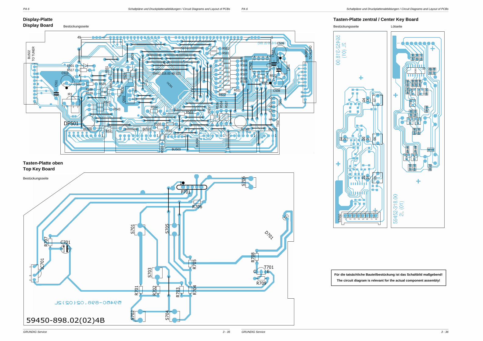
PA 6 Schaltpläne und Druckplattenabbildungen / Circuit Diagrams and Layout of PCBs PA 6 Schaltpläne und Druckplattenabbildungen / Circuit Diagrams and Layout of PCBs
GRUNDIG Service GRUNDIG Service
R517
R53
7
R526
R522
R521
R53
3
R53
4
R53
2
R53
6
R512
R501
CE
T502
49 1
DP501
1
BU507
1
BU506
1
BU505
1
BU508
1
BU
504
C50
7C51
2
C506
C513
C508
C509
L501D501
85
4 1
IC50
2R503
R509
R507R506R504
R508
R511
R52
8
R539
3 21
IR1
13
Q50
2
BR
514
R52
7
R55
1
R541
CE T5
01
R52
9
R543
R542
51
BU503
111
BU
502
111
BU
501
R552
R538
C51
1
R554
R556
R553
R502
59452-316.00 4B (02)
TO A
UD
IO
TO T
UN
ER
6465
180
24
25
4041
CIC501
8
D4
S6
2 3 4 5 6 71
D3
D1
D2
S7
S5
ST6
50
CR
612
CT6
06
CC
601
IC60
1
CR
617
CR
629
CR
622
CR
613
CR
624
CR
626
CR
619
CR
623
CR
620
CR
621
CR
625
CR
628
CR
627
CR
618
CR
616
CR
611
CR
614
CR
610
CR
615
CT6
07
CT6
05
CT6
04
CT6
01
CT6
03
CT6
02
CR630
3 - 363 - 35
Display-PlatteDisplay Board
Tasten-Platte obenTop Key Board
Tasten-Platte zentral / Center Key Board
Bestückungsseite Lötseite3
21 IC70
1R70
7
C701+
R70
1S70
2
S70
3
S70
4
S70
1
S70
5
S70
6
R70
2
R70
3
R70
4R70
5 R70
8
R709
T701
R706
P701
1
C E
D701
59450-898.02(02)4B
Für die tatsächliche Bauteilbestückung ist das Schaltbild maßgebend!
The circuit diagram is relevant for the actual component assembly!
Bestückungsseite
Bestückungsseite
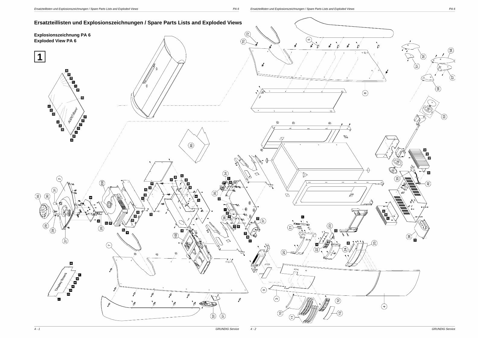
Ersatzteillisten und Explosionszeichnungen / Spare Parts Lists and Exploded Views PA 6 Ersatzteillisten und Explosionszeichnungen / Spare Parts Lists and Exploded Views PA 6
GRUNDIG Service GRUNDIG Service4 - 24 - 1
Ersatzteillisten und Explosionszeichnungen / Spare Parts Lists and Exploded Views
Explosionszeichnung PA 6Exploded View PA 6
1

GR
UN
DIG
Service
4 - 3
PA
6E
rsatzteillisten und Explosionszeichnungen / S
pare Parts Lists and E
xploded View
s
12
3
4
56
7
8
9!
" %
&
$
™
#
(
Explosionszeichnung C
assetten-LoadingE
xploded View
Tape Loading
2
ÄNDERUNGEN VORBEHALTEN / SUBJECT TO ALTERATION
ErsatzteillisteSpare Parts List
PA 6-I
HIFI / AUDIO
MATERIAL-NR. / PART NO.: 95540 310 5000BESTELL-NR. / ORDER NO.: G.LI 16-51 DUNKEL-GRAU
1
7 / 2000
POS. NR. ABB. MATERIAL-NR. ANZ. BEZEICHNUNG DESCRIPTIONPOS. NO. FIG. PART NUMBER QTY. d ©
95540 310 5000 PA 6-I PA 6-IKEIN E-TEIL NO SPARE PART
0002.000 1 55398 201 0107 ABDECKUNG OBEN (PA6) COVER TOP (PA6)0003.000 1 55403 300 5000 FRONTTEIL OBEN (PA 6) FRONT PART TOP (PA 6)0004.000 1 55403 301 5000 FRONTTEIL UNTEN (PA 6) FRONT PART BOTTOM (PA 6)0005.000 1 55398 298 0000 8 ABDECKUNG CLIP COVER CLIP0007.000 1 55403 500 0100 SEITENWAND LINKS SIDE PANEL LEFT0008.000 1 55403 501 0100 SEITENWAND RECHTS SIDE PANEL RIGHT0009.000 1 55317 405 0100 FOLIE FILTER FOIL FILTER0010.000 1 55403 209 0000 FENSTER DISPLAY (PA 6) WINDOW DISPLAY (PA 6)0011.000 1 55403 150 0100 BLENDENSATZ CD KPL (PA6) MASK SET CD CPL (PA6)0012.000 1 55403 212 0100 HALTER BLENDE CF (PA 6) HOLDER MASK CF (PA 6)0013.000 1 55403 305 5000 BLENDE CF (PA 6) MASK CF (PA 6)0015.000 52025 230 0000 LED-HALTER LED HOLDER0018.000 55301 264 0000 LED-HALTER LED HOLDER0020.000 1 55403 202 0100 GEHAEUSE CD/CF KEYS (PA6) CABINET CD/CF KEYS (PA6)0021.000 1 55403 204 0200 4 TASTE CF/CD (POLARIS) (PA6) KEY CF/CD (POLARIS) (PA6)0022.000 1 55403 207 0200 TASTEN-SATZ SELECT (POLARIS) KEYS SET SELECT (POLARIS)0023.000 1 09621 147 0100 STEREO-KOPFHOERERB.1-FACH PHONE SOCKET STEREO 1 FOL0024.000 1 55403 206 0100 GEHAEUSE SELECT KEYS (PA6) CABINET SELECT KEYS (PA6)0025.000 1 55403 210 0000 FENSTER STAND-BY (PA 6) WINDOW STAND-BY (PA 6)0026.000S1 59400 310 0000 NETZSCHALTER (SDLCIP) MAINS SWITCH0027.000 1 55398 216 0100 TASTENSTREIFEN KEY STRIP0028.000 1 55398 250 0000 LINSE NETZ LENS POWER0029.000 1 55398 210 0100 NETZTASTE POWER KEY0030.000 1 55398 212 1200 TASTE SUPER-BASS PA 6 (POLARIS) KEY SUPER-BASS PA 6 (POLARIS)0031.000 1 55398 252 0000 LINSE RC LENS RC0034.000 1 09623 449 0000 CINCH-BUCHSE 4-FACH JALCO CINCH SOCKET 4 FOLD JALCO0035.000 1 81261 252 9300 KOAX-BUCHSE LP AJ-2021 J COAX BUCHSE PCB AJ-20210036.000 1 59430 027 0200 TRAFO STAND BY TRANSFORMER STAND BY0037.000 1 59430 062 0100 TRAFO AMPL.99R-072 (PA 6) TRANSFORMER AMPL.99R-0720038.000S1 59430 064 0100 NETZTRAFO SYSTEM 99R-071 POWER TRANSFORMER SYSTEM0039.000S1 82909 913 0800 NETZKABEL KPL GWN9.20 WF POWER CABLE KPL GWN9.20 S0040.000 1 09666 613 0000 NETZKABEL-ZUGENTLASTUNG MAINS LEAD-CORD GRIP0041.000 09621 113 0200 10 SICHERUNGSHALTER FUSE HOLDER0042.000S 29303 452 0200 NETZSTECKER-UNTERTEIL KPL MAINS PLUG LOWER PART CPL0045.000 59401 031 0000 DETEKTORSCHALTER DETECTOR SWITCH0046.000 55135 215 0500 2 DISPLAYHALTER DISPLAY HOLDER0051.000 1 55403 218 0200 2 ABDECKUNG FUSS (POLARIS) COVER FOOT (POLARIS) (PA6)0052.000 1 55403 217 0200 2 FUSS HINTEN (POLARIS) (PA6) FOOT BEHIND (POLARIS) (PA6)0053.000 1 55403 240 0200 2 RAD KPL M.KAPPE (POLARIS) WHEEL CPL W.CAP (POLARIS)0054.000 55301 400 0000 2 FUSS GUMMI FOOT RUBBER0055.000 55301 401 0000 FUSS GUMMI FOOT RUBBER0056.000 55398 270 0200 FUSS AUSSEN/HINTEN (POLARIS) FOOT OUTSIDE/BACK (POLARIS)0057.000 55398 271 0200 FUSS INNEN/HINTEN (POLARIS) FOOT INSIDE/BACK (POLARIS)0060.000 55403 603 0100 LAUTSPRECHER TIEFTON (PA6) LOUDSPEAKER WOOFER (PA 6)0063.000 59709 049 0100 WURFANTENNE KPL WIRE AERIAL CPL0065.000 81229 951 1800 4 GLIMMERSCHEIBE GS127 18/25,5 MICA WASHER GS127 18/25,50067.000 09647 020 9700 2 FERRITPERLE 2 FERRIT BEAD 20068.000 81049 820 6900 2 FERRITPERLE BD3/0,7/4-4S2 FERRITE BEAD BD3/0.7/4-4S0070.000 1 55398 296 0000 6 BUCHSE SOCKET0072.000 1 81160 040 2100 6 LIBLSHR GWN1.60 C4,2X19 K TAPPING SCR.GWN1.60 C4.2X0075.000 55398 114 0000 2 DEMONTAGEBUEGEL DISMOUNTING BOW0080.000 59852 001 0000 IR-EMPFAENGER TFMS 5360 TFK IR RECEIVER TFMS 5360 TFK0085.000 55398 115 0000 ABDECKUNG INNEN COVER INTERIOR

4 - 4G
RU
ND
IG S
ervice
Ersatzteillisten und E
xplosionszeichnungen / Spare P
arts Lists and Exploded V
iews
PA
6
ÄNDERUNGEN VORBEHALTEN / SUBJECT TO ALTERATION
POS. NR. ABB. MATERIAL-NR. ANZ. BEZEICHNUNG DESCRIPTIONPOS. NO. FIG. PART NUMBER QTY. d ©
0095.000 1 59802 620 5000 FERNBEDIENUNG (PA 6) REMOTE CONTROL (PA 6)0096.000 75955 028 1000 TUER BATTERIE DOOR BATTERY
0100.000 52318 501 0000 LOADING KPL LOADING CPLKEIN E-TEIL NO SPARE PART
0101.000 2 52304 240 0000 CASSETTENSCHUBLADE CASSETTE DRAWER0103.000 2 52304 243 0000 SCHUBLADENFUEHRUNG LINKS CASSETTE DOOR SUPPORT LHS0104.000 2 81260 296 7700 2 NADELROLLE GWN7.02 3X33,2 NEEDLE ROLLER GWN 7.02 3X33,20105.000 2 52304 241 0000 RAD 2 WHEEL 20106.000 2 52304 242 0000 RAD 3 WHEEL 30107.000 2 59852 002 0000 DC MINI-MOTOR (MITSUMI) DC MINI MOTOR (MITSUMI)0108.000 2 52304 245 0000 RAD 1 WHEEL 10109.000 2 52304 390 0000 TREIBRIEMEN DRIVING BELT0110.000 2 52304 247 0000 RIEGEL LINKS LOCK LEFT0111.000 2 52304 244 0000 SCHUBLADENRUEHRUNG RECHTS CASSETTE DOOR SUPPORT RHS0112.000 2 52304 249 0000 RIEGEL RECHTS LOCK RIGHT0113.000 2 52304 248 0000 CASSETTENHEBEL CASSETTE LEVER0114.000 2 52304 130 0000 CASSETTENSCHACHT-HALTER CASSETTENCOMPARTMENT-HOLD0115.000 2 59726 012 0000 X CASSETTENLAUFWERK (TN 1800 D) TAPE DRIVE (TN 1800 D)0122.000 2 09619 071 0000 3 ZUGFEDER TENSION SPRING0123.000 2 52304 141 0000 FEDER 1 SPRING 10125.000 2 59852 049 0000 CASSETTENEINLAGE CASSETTE INSERT
0200.000 1 59726 017 0000 LAUFWERK CD-V300DW 3CD CD-DRIVE CD-V300DW 3CD0300.000 59472 010 0000 LP CDC-LOGIK BST.KPL. PCB CDC LOGIC ASSY CPL0400.000 59472 012 0000 LP CDC-SERVO BST.KPL. PCB CDC SERVO ASSY CPL
55403 941 0200 BEDIENUNGSANLEITUNG D/I OPERATING INSTRUCTIONS D/I55403 941 0800 BEDIENUNGSANLEITUNG F/NL OPERATING INSTRUCTIONS F/NL55403 941 1100 BEDIENUNGSANLEITUNG GB/FIN OPERATING INSTRUCTIONS GB/FIN55403 941 1400 BEDIENUNGSANLEITUNG S/DK OPERATING INSTRUCTIONS SK/DK55403 941 1900 BEDIENUNGSANLEITUNG E/P OPERATING INSTRUCTIONS E/P72010 760 7000 SERVICE MANUAL D/GB SERVICE MANUAL D/GB
X = SIEHE GESONDERTE E-LISTE X = SEE SEPARATE PARTS LIST
POS. NR. MATERIAL-NR. BEZEICHNUNGPOS. NO. PART NUMBER DESCRIPTION
POS. NR. MATERIAL-NR. BEZEICHNUNGPOS. NO. PART NUMBER DESCRIPTION
BR 00910 83080 100 0200 SMD GLR DF02SBR 00920 83080 100 0200 SMD GLR DF02SBR 00930 83080 100 0200 SMD GLR DF02S
C 00005 84100 015 6800 ELKO 6800UF 50V USP (A) MC 00006 84100 015 6800 ELKO 6800UF 50V USP (A) MC 00205 86999 013 7000 TR.17 15/100PF VCT 56 ALPC 00206 86999 013 7000 TR.17 15/100PF VCT 56 ALPC 00255 86057 671 5600 SSPN 270PF 10% 400V -GRC 00401 84529 695 5500 ELKO 4700UF 25V H25 YK RC 00801 S 86601 970 4300 KERKO SI A 3300PF 20% 250VC 00912 84529 961 5500 ELKO 4700UF 20% 25V CBC 00922 84529 961 4700 ELKO 1000UF 20% 25V CBC 00932 84529 961 5500 ELKO 4700UF 20% 25V CBC 00950 S 86601 970 4300 KERKO SI A 3300PF 20% 250V
CD 00640 83260 306 7300 SMD LE-DIODE LTA673-R SI
CIC 00501 83057 524 5000 SMD IC M38B59EFFP MITCIC 00601 83057 340 9400 SMD IC HEF4094BT AV215-G1
CT 00601 83010 048 4800 SMD TRANS BC848B/ BC847BCT 00602 83010 048 4800 SMD TRANS BC848B/ BC847BCT 00603 83010 048 4800 SMD TRANS BC848B/ BC847BCT 00604 83010 048 4800 SMD TRANS BC848B/ BC847BCT 00605 83010 048 4800 SMD TRANS BC848B/ BC847BCT 00606 83010 048 4800 SMD TRANS BC848B/ BC847B
CT 00607 83010 048 4800 SMD TRANS BC848B/ BC847B
D 00001 83099 444 1200 LE DIODE TLHY 4405 AS12 AD 00001 83253 131 0200 MELF DIODE BAV102D 00001 83092 154 0100 DIODE 1 N 5401 G GI/FAG GD 00002 83253 131 0200 MELF DIODE BAV102D 00002 83099 444 1200 LE DIODE TLHY 4405 AS12 AD 00002 83092 154 0100 DIODE 1 N 5401 G GI/FAG GD 00003 83099 444 1200 LE DIODE TLHY 4405 AS12 AD 00003 83092 154 0100 DIODE 1 N 5401 G GI/FAG GD 00004 83092 154 0100 DIODE 1 N 5401 G GI/FAG GD 00004 83099 444 1200 LE DIODE TLHY 4405 AS12 AD 00016 83092 150 4500 DIODE 1N4148 AV619 -GAD 00101 83097 200 9100 Z-DIODE 9,1 C 0,5W AV619D 00111 83092 150 4500 DIODE 1N4148 AV619 -GAD 00111 83250 041 4800 SMD DIODE LS 4148D 00112 83092 150 4500 DIODE 1N4148 AV619 -GAD 00116 83092 150 4500 DIODE 1N4148 AV619 -GAD 00126 83250 041 4800 SMD DIODE LS 4148D 00161 83250 041 4800 SMD DIODE LS 4148D 00162 83250 041 4800 SMD DIODE LS 4148D 00360 83095 341 4900 MELF-DIODE LL 4148 TFK/ITD 00361 83095 341 4900 MELF-DIODE LL 4148 TFK/ITD 00362 83095 341 4900 MELF-DIODE LL 4148 TFK/ITD 00363 83095 341 4900 MELF-DIODE LL 4148 TFK/ITD 00364 83095 341 4900 MELF-DIODE LL 4148 TFK/ITD 00365 83095 341 4900 MELF-DIODE LL 4148 TFK/IT
ÄNDERUNGEN VORBEHALTEN / SUBJECT TO ALTERATION
POS. NR. MATERIAL-NR. BEZEICHNUNGPOS. NO. PART NUMBER DESCRIPTION
POS. NR. MATERIAL-NR. BEZEICHNUNGPOS. NO. PART NUMBER DESCRIPTION
D 00366 83095 341 4900 MELF-DIODE LL 4148 TFK/ITD 00367 83095 341 4900 MELF-DIODE LL 4148 TFK/ITD 00370 83095 341 4900 MELF-DIODE LL 4148 TFK/ITD 00371 83095 341 4900 MELF-DIODE LL 4148 TFK/ITD 00372 83095 341 4900 MELF-DIODE LL 4148 TFK/ITD 00373 83095 341 4900 MELF-DIODE LL 4148 TFK/ITD 00402 83092 150 4500 DIODE 1N4148 AV619 -GAD 00403 83092 150 4500 DIODE 1N4148 AV619 -GAD 00404 83092 150 2000 DIODE 1 N 4004 -GAD 00405 83092 150 2000 DIODE 1 N 4004 -GAD 00406 83092 150 2000 DIODE 1 N 4004 -GAD 00407 83092 150 2000 DIODE 1 N 4004 -GAD 00408 83097 200 4300 Z DIODE 4,3 C 0,5WD 00411 83097 200 4300 Z DIODE 4,3 C 0,5WD 00413 83092 150 4500 DIODE 1N4148 AV619 -GAD 00414 83092 150 4500 DIODE 1N4148 AV619 -GAD 00415 83092 150 4500 DIODE 1N4148 AV619 -GAD 00417 83092 150 4500 DIODE 1N4148 AV619 -GAD 00418 83092 150 4500 DIODE 1N4148 AV619 -GAD 00419 83092 150 4500 DIODE 1N4148 AV619 -GAD 00421 83092 150 4500 DIODE 1N4148 AV619 -GAD 00422 83092 150 4500 DIODE 1N4148 AV619 -GAD 00424 83092 150 4500 DIODE 1N4148 AV619 -GAD 00425 83092 150 4500 DIODE 1N4148 AV619 -GAD 00426 83092 150 4500 DIODE 1N4148 AV619 -GAD 00427 83092 150 4500 DIODE 1N4148 AV619 -GAD 00428 83092 150 4500 DIODE 1N4148 AV619 -GAD 00501 83092 150 4500 DIODE 1N4148 AV619 -GAD 00602 83250 041 4800 SMD DIODE LS 4148D 00603 83250 041 4800 SMD DIODE LS 4148D 00604 83300 040 0400 MELF DIODE LL4004D 00605 83300 040 0400 MELF DIODE LL4004D 00630 83250 041 4800 SMD DIODE LS 4148D 00701 83099 942 3200 LE DIODE LTL 4232 N BIN 3D 00900 83092 150 2000 DIODE 1 N 4004 -GAD 00901 83093 840 4700 SMD-Z DIODE BZX 84 C4V7D 00910 83095 341 4900 MELF-DIODE LL 4148 TFK/ITD 00911 83095 341 4900 MELF-DIODE LL 4148 TFK/ITD 00912 83095 341 4900 MELF-DIODE LL 4148 TFK/ITD 00920 83095 341 4900 MELF-DIODE LL 4148 TFK/ITD 00921 83095 341 4900 MELF-DIODE LL 4148 TFK/ITD 00922 83095 341 4900 MELF-DIODE LL 4148 TFK/ITD 00923 83092 150 2000 DIODE 1 N 4004 -GAD 01601 83303 960 2700 MELF DIODE ZPD2V7
DP 00501 55401 803 0000 DISPLAY FV719GN FUTABADP 00501 59740 017 0100 DISPLAY (FUTABA)
F 00101 86028 220 7000 KERFIL #70/Z 10,7MHZF 00101 81419 100 6000 FILTER 10X10 #60 SIGN9100F 00102 86028 220 7000 KERFIL #70/Z 10,7MHZF 00102 81419 100 6000 FILTER 10X10 #60 SIGN9100F 00111 81411 250 1900 SPULE 10X10 #19 FARBE358F 00112 81411 250 1900 SPULE 10X10 #19 FARBE358F 00141 81411 114 5000 FILTER 7X7 #450 10,7MHZF 00171 81419 100 6200 FILTER 10X10 #62 2FACH FAF 00172 81419 100 6200 FILTER 10X10 #62 2FACH FAF 00401 86023 310 8600 CER.RES.86/13 CST 4.0 MGWF 00601 81406 011 7700 AC FILTER 3A/250V
FE 00100 59420 348 0000 FRONTEND MODEL FE 415-G11
IC 00001 83053 372 9400 IC TDA7294V SGSIC 00101 83052 743 3000 IC UPC1330HA NECIC 00101 83053 372 9400 IC TDA7294V SGSIC 00102 83052 585 5000 IC CXA1550P SONYIC 00103 83052 585 9800 IC CXA1598S SONYIC 00110 83052 043 1700 IC LM317T NSC/MOT/SGSIC 00120 83057 657 1800 SMD IC LC7218MIC 00140 83057 571 3700 SMD IC LA1837M
IC 00180 83058 265 7900 SMD IC SAA6579T PHI AV215IC 00240 83052 628 2100 IC LC7821 SANYOIC 00270 83058 473 1300 SMD IC TDA7313D-013TR AV2IC 00360 83058 074 5600 SMD IC NJM4556DIC 00370 83057 593 9400 SMD IC LM393DIC 00401 83052 057 0300 IC MC7805CTIC 00402 83052 043 4100 IC LM340AT-12 NSC >>>IC 00403 83056 024 0000 IC X24C00P XICORIC 00404 83052 074 7700 IC M37471-M4-458SP MITIC 00405 83054 081 3500 IC TA8135P TOSIC 00502 83056 024 3200 IC M24C32IC 00601 83057 647 0600 SMD IC L7805CD2T MOTIC 00602 83058 788 2000 SMD IC UPD78F0034AGC-AB8IC 00603 83057 735 7300 SMD IC 74HCT573MIC 00604 83048 462 6400 SMD IC UL6264AIC 00605 83057 658 7000 SMD IC LC89170M SYOIC 00700 83058 074 5600 SMD IC NJM4556DIC 00900 83052 043 3700 IC LM337TIC 00902 83057 598 3300 SMD IC LM833DIC 00903 83057 598 3300 SMD IC LM833DIC 00904 83057 598 3300 SMD IC LM833DIC 00905 83057 598 3300 SMD IC LM833DIC 00910 83057 647 0600 SMD IC L7805CD2T MOTIC 00920 83057 647 0600 SMD IC L7805CD2T MOTIC 00930 83052 043 4100 IC LM340AT-12 NSC >>>IC 00931 83057 647 0600 SMD IC L7805CD2T MOTIC 01601 83058 273 7800 SMD IC SAA7378GP PHIIC 01602 83058 415 4900 SMD IC TDA1549T PHIIC 01603 83058 470 7300 SMD IC TDA7073A/ATIC 01604 83058 470 7300 SMD IC TDA7073A/ATIC 01605 83058 470 7300 SMD IC TDA7073A/ATIC 01606 83048 381 1500 SMD IC TZA1015T/N4 PHI
IR 00001 83054 617 3600 IC TSOP1736/ TSOP1236 TE
L 00101 81405 264 8000 SMD DR 1206 0,33UH 20% AVL 00111 81411 254 0600 SPULE 10X10 #406 FARBE638L 00181 81405 264 6700 SMD DR 1206 22UH 10%L 00501 81405 263 6100 DR 0411 10UH 5% AV619 -AM
Q 00120 83821 900 7200 QUARZ 7,2 MHZ Q 190/A (GEQ 00181 83821 704 3300 QUARZ #170 A/C 4,332MHZQ 00501 83822 007 9700 SCHWINGQUARZ 32,768 KHZ /Q 00502 86023 310 8600 CER.RES.86/13 CST 4.0 MGWQ 00601 86023 310 8800 CER.RES.88/11 CST 4.19 MGQ 01601 83822 060 8400 QUARZ #206 8,4672MHZ 30PF
R 00135 87920 021 5400 ESTR.S6 22 KOHM LINR 00136 87920 021 5400 ESTR.S6 22 KOHM LINR 00141 87920 021 6400 ESTR.S6 100 KOHM LINR 00142 87920 021 6400 ESTR.S6 100 KOHM LINR 00149 S 87011 180 3300 KSW SI B 22 OHM 5% AV619R 00155 S 87011 180 3300 KSW SI B 22 OHM 5% AV619R 00169 87920 021 5400 ESTR.S6 22 KOHM LINR 00182 87920 021 5400 ESTR.S6 22 KOHM LINR 00229 S 87667 010 3300 KSW SI A 22 OHM 5% AV619R 00275 S 87011 180 2500 KSW SI B 10 OHM 5% AV619R 00289 S 87011 180 3300 KSW SI B 22 OHM 5% AV619R 00360 S 87011 180 2500 KSW SI B 10 OHM 5% AV619R 00361 S 87011 180 2500 KSW SI B 10 OHM 5% AV619R 00383 S 87011 180 2500 KSW SI B 10 OHM 5% AV619R 00482 87920 011 4600 ESTR.P6/A 4,7 KOHM LINR 00701 S 87011 180 2500 KSW SI B 10 OHM 5% AV619R 01708 S 87011 180 1300 KSW SI B 3,3 OHM 5% AV619
REL00900 83120 030 1200 RELAIS G2R-1A 12V DC OMRO
S 00001 81340 201 8100 TASTSCHALTER SKHVBB ALPSS 00002 81340 201 8100 TASTSCHALTER SKHVBB ALPSS 00003 81340 201 8100 TASTSCHALTER SKHVBB ALPS

GR
UN
DIG
Service
4 - 5
PA
6E
rsatzteillisten und Explosionszeichnungen / S
pare Parts Lists and E
xploded View
s
ErsatzteillisteSpare Parts List
PA 6 SPEAKER I
HIFI/AUDIO
MATERIAL-NR. / PART NO.: 75202 010 5200BESTELL-NR. / ORDER NO.: GNI0952 DUNKEL-GRAU/DARK GREY
1
12 / 99
POS. NR. ABB. MATERIAL-NR. ANZ. BEZEICHNUNG DESCRIPTIONPOS. NO. FIG. PART NUMBER QTY. d ©
75202 010 5200 PA 6 SPEAKER (PA 3-SFS G.NF 09-52 X) PA 6 SPEAKER (PA 3-SFS G.NF 09-52 X)KEIN E-TEIL NO SAPRE PART
0010.000 51020 210 0000 2 ABDECKUNG LAUTSPR. M. BESPANNUNG COVER SPEAKER W.COVERING0020.000 19144 121 6100 2 LAUTSPRECHER MITTELTON LOUDSPEAKER MIDRANGE0030.000 19115 011 4700 2 LAUTSPRECHER HOCHTON LOUDSPEAKER TWEETER
ÄNDERUNGEN VORBEHALTEN / SUBJECT TO ALTERATION
( ! )!Es gelten die Vorschriften und Sicherheitshinweise
gemäß dem Service Manual "Sicherheit", Mat.-Num-mer 72010 800 0000, sowie zusätzlich die eventuellabweichenden, landesspezifischen Vorschriften!
The regulations and safety instructions shall be validas provided by the "Safety" Service Manual, partnumber 72010 800 0000, as well as the respectivenational deviations.
POS. NR. MATERIAL-NR. BEZEICHNUNGPOS. NO. PART NUMBER DESCRIPTION
POS. NR. MATERIAL-NR. BEZEICHNUNGPOS. NO. PART NUMBER DESCRIPTION
S 00004 81340 201 8100 TASTSCHALTER SKHVBB ALPSS 00005 81340 201 8100 TASTSCHALTER SKHVBB ALPSS 00006 81340 201 8100 TASTSCHALTER SKHVBB ALPSS 00007 81340 201 8100 TASTSCHALTER SKHVBB ALPS
SI 00001S 83156 230 0800 SI LOET T4A 250VSI 00002S 83156 230 0800 SI LOET T4A 250VSI 00501S 83156 162 0500 SI LOET T800MA 250VSI 00900S 83156 140 0100 SI 5X20 T500MA L 250VSI 00910S 83156 160 0300 SI 5X20 T800MA L 250VSI 00920S 83156 120 0200 SI 5X20 T315MA L 250VSI 00930S 83156 170 0400 SI 5X20 T1A L 250VSI 00940S 83156 170 0600 SI 5X20 T2,5A L 250V
T 00028 83032 415 4600 TRANS.BC 546 B GEG.AMMO-PT 00029 83032 415 4600 TRANS.BC 546 B GEG.AMMO-PT 00101 83010 048 4800 SMD TRANS BC848B/ BC847BT 00101 83032 595 5000 TRANS.BC 550 C SIE/PHI GET 00102 83011 308 4000 SMD TRANS BF840T 00102 83032 595 5000 TRANS.BC 550 C SIE/PHI GET 00103 83032 595 5000 TRANS.BC 550 C SIE/PHI GET 00104 83032 595 5000 TRANS.BC 550 C SIE/PHI GET 00105 83032 075 4800 TRANS BC548C/ BC547C PHIT 00106 83032 075 4800 TRANS BC548C/ BC547C PHIT 00107 83032 055 5800 TRANS BC558B/ BC557B PHIT 00108 83032 075 4800 TRANS BC548C/ BC547C PHIT 00109 83032 075 4800 TRANS BC548C/ BC547C PHIT 00111 83032 733 2700 TRANS BC327-25 AV330T 00125 83032 075 4800 TRANS BC548C/ BC547C PHIT 00126 83032 075 4800 TRANS BC548C/ BC547C PHIT 00127 83032 075 4800 TRANS BC548C/ BC547C PHIT 00131 83026 380 3000 TRANS.2 SK 30 A-TM-Y1 GEGT 00131 83032 075 4800 TRANS BC548C/ BC547C PHIT 00132 83010 068 4800 SMD TRANS BC848C/ BC847CT 00151 83010 048 4800 SMD TRANS BC848B/ BC847BT 00153 83022 002 5600 TRANS BC338-40/ BC337-40T 00154 83022 002 5600 TRANS BC338-40/ BC337-40T 00155 83032 075 4800 TRANS BC548C/ BC547C PHIT 00156 83032 733 2700 TRANS BC327-25 AV330T 00158 83032 733 3700 TRANS.BC 337-25 GEG.AMMO-T 00161 83032 075 4800 TRANS BC548C/ BC547C PHIT 00161 83010 048 4800 SMD TRANS BC848B/ BC847BT 00162 83010 038 5800 SMD TRANS BC858B/ BC857BT 00163 83010 048 4800 SMD TRANS BC848B/ BC847BT 00164 83010 048 4800 SMD TRANS BC848B/ BC847BT 00171 83032 675 5000 TRANS.BC 550 C GEG.AMMO-PT 00172 83032 675 5000 TRANS.BC 550 C GEG.AMMO-PT 00173 83032 075 4800 TRANS BC548C/ BC547C PHIT 00174 83032 055 5800 TRANS BC558B/ BC557B PHIT 00175 83032 075 4800 TRANS BC548C/ BC547C PHIT 00176 83032 075 4800 TRANS BC548C/ BC547C PHIT 00177 83032 075 4800 TRANS BC548C/ BC547C PHIT 00178 83032 075 4800 TRANS BC548C/ BC547C PHIT 00190 83032 075 4800 TRANS BC548C/ BC547C PHIT 00192 83032 075 4800 TRANS BC548C/ BC547C PHIT 00202 83010 068 4800 SMD TRANS BC848C/ BC847CT 00203 83010 068 4800 SMD TRANS BC848C/ BC847CT 00370 83010 048 4800 SMD TRANS BC848B/ BC847BT 00371 83010 048 4800 SMD TRANS BC848B/ BC847BT 00401 83032 055 4800 TRANS BC548B/ BC547B PHIT 00402 83032 075 4800 TRANS BC548C/ BC547C PHIT 00403 83032 876 4000 TRANS.BC 640 GEG.AMMO-PACT 00404 83032 733 2700 TRANS BC327-25 AV330T 00405 83032 733 2700 TRANS BC327-25 AV330T 00406 83032 055 4800 TRANS BC548B/ BC547B PHIT 00407 83032 055 4800 TRANS BC548B/ BC547B PHI
T 00408 83032 055 4800 TRANS BC548B/ BC547B PHIT 00409 83032 055 4800 TRANS BC548B/ BC547B PHIT 00411 83032 876 4000 TRANS.BC 640 GEG.AMMO-PACT 00412 83032 876 3900 TRANS.BC 639 GEG.AMMO-PACT 00413 83032 876 4000 TRANS.BC 640 GEG.AMMO-PACT 00414 83032 876 3900 TRANS.BC 639 GEG.AMMO-PACT 00415 83032 055 4800 TRANS BC548B/ BC547B PHIT 00416 83032 055 4800 TRANS BC548B/ BC547B PHIT 00417 83032 075 4800 TRANS BC548C/ BC547C PHIT 00419 83032 055 5800 TRANS BC558B/ BC557B PHIT 00421 83032 055 4800 TRANS BC548B/ BC547B PHIT 00422 83032 055 4800 TRANS BC548B/ BC547B PHIT 00423 83032 876 3900 TRANS.BC 639 GEG.AMMO-PACT 00425 83032 055 5800 TRANS BC558B/ BC557B PHIT 00501 83032 055 5800 TRANS BC558B/ BC557B PHIT 00502 83032 075 4800 TRANS BC548C/ BC547C PHIT 00601 83011 900 6000 SMD TRANS BSP60T 00602 83010 048 4800 SMD TRANS BC848B/ BC847BT 00630 83010 048 4800 SMD TRANS BC848B/ BC847BT 00700 83010 048 4800 SMD TRANS BC848B/ BC847BT 00701 83032 055 4800 TRANS BC548B/ BC547B PHIT 00701 83010 048 4800 SMD TRANS BC848B/ BC847BT 00702 83010 038 5800 SMD TRANS BC858B/ BC857BT 00911 83010 068 4800 SMD TRANS BC848C/ BC847CT 00912 83010 068 4800 SMD TRANS BC848C/ BC847CT 00913 83010 038 5800 SMD TRANS BC858B/ BC857BT 00914 83010 038 5800 SMD TRANS BC858B/ BC857BT 00916 83010 038 5800 SMD TRANS BC858B/ BC857BT 00917 83010 068 4800 SMD TRANS BC848C/ BC847CT 00920 83010 048 4800 SMD TRANS BC848B/ BC847BT 01601 83010 048 4800 SMD TRANS BC848B/ BC847BT 01602 83010 048 4800 SMD TRANS BC848B/ BC847BT 01670 83010 048 4800 SMD TRANS BC848B/ BC847BT 01671 83010 048 4800 SMD TRANS BC848B/ BC847BT 01672 83010 038 5800 SMD TRANS BC858B/ BC857B
ÄNDERUNGEN VORBEHALTEN / SUBJECT TO ALTERATION
( ! )!Es gelten die Vorschriften und Sicherheitshinweise
gemäß dem Service Manual "Sicherheit", Mat.-Num-mer 72010 800 0000, sowie zusätzlich die eventuellabweichenden, landesspezifischen Vorschriften!
The regulations and safety instructions shall be validas provided by the "Safety" Service Manual, partnumber 72010 800 0000, as well as the respectivenational deviations.

4 - 6G
RU
ND
IG S
ervice
Ersatzteillisten und E
xplosionszeichnungen / Spare P
arts Lists and Exploded V
iews
PA
6
ErsatzteillisteSpare Parts List
PA 6-II
HIFI / AUDIO
MATERIAL-NR. / PART NO.: 95540 311 4900BESTELL-NR. / ORDER NO.: GLI1967 AHORN
1
5 / 2000
POS. NR. ABB. MATERIAL-NR. ANZ. BEZEICHNUNG DESCRIPTIONPOS. NO. FIG. PART NUMBER QTY. d ©
95540 311 4900 PA6-II AHORN PA6-II AHORNKEIN E-TEIL NO SPARE PART
0002.000 55398 201 0400 ABDECKUNG OBEN (LIGHT GREY) COVER TOP (LIGHT GREY)0005.000 55398 298 0400 8 ABDECKUNG CLIP (LIGHT GREY) COVER CLIP (LIGHT GREY)0007.000 55403 500 0200 SEITENWAND LINKS (AHORN) SIDE PANEL LHS (AHORN)0008.000 55403 501 0200 SEITENWAND RECHTS (AHORN) SIDE PANEL RHS (AHORN)0020.000 55403 202 0400 GEHAEUSE CD/CF KEYS (LIGHT GREY) HOUSING CD/CF KEYS (LIGHT GREY)0024.000 55403 206 0400 GEHAEUSE SELECT KEYS (LIGHT GREY) HOUSING SELECT KEYS (LIGHT GREY)0029.000 55398 210 1400 TASTE NETZ PA 6 (LIGHT GREY) KEY POWER PA 6 (LIGHT GREY)
ALLE WEITEREN TEILE SIEHE E-LISTE FOR ALL OTHER PARTS SEEPA 6 PA 6MAT.-NR.: 95540 310 5000 PART NO.: 95540 310 5000BESTELL-NR.: G. LI 16-51 ORDER NO.: G. LI 16-51AUSGABE 5/2000 EDITION 5/2000
ÄNDERUNGEN VORBEHALTEN / SUBJECT TO ALTERATION
( ! )!Es gelten die Vorschriften und Sicherheitshinweise
gemäß dem Service Manual "Sicherheit", Mat.-Num-mer 72010 800 0000, sowie zusätzlich die eventuellabweichenden, landesspezifischen Vorschriften!
The regulations and safety instructions shall be validas provided by the "Safety" Service Manual, partnumber 72010 800 0000, as well as the respectivenational deviations.
ErsatzteillisteSpare Parts List
PA 6 SPEAKER II
HIFI / AUDIO
MATERIAL-NR. / PART NO.: 75203 010 5000BESTELL-NR. / ORDER NO.: GNI1052 HELL-GRAU/LIGHT GREY
1
12 / 99
POS. NR. ABB. MATERIAL-NR. ANZ. BEZEICHNUNG DESCRIPTIONPOS. NO. FIG. PART NUMBER QTY. d ©
75203 010 5000 PA 6 SPEAKER II HELLGRAU PA 6 SPEAKER II LIGHT GREYKEIN E-TEIL NO SPARE PART
0010.000 51020 210 8200 2 ABDECKUNG LAUTSPR. M.BESPANNUNG COVER SPEAKER W.COVERING0020.000 19144 121 6100 2 LAUTSPRECHER MITTELTON LOUDSPEAKER MIDRANGE0030.000 19115 011 4700 2 LAUTSPRECHER HOCHTON LOUDSPEAKER TWEETER
ÄNDERUNGEN VORBEHALTEN / SUBJECT TO ALTERATION
( ! )!Es gelten die Vorschriften und Sicherheitshinweise
gemäß dem Service Manual "Sicherheit", Mat.-Num-mer 72010 800 0000, sowie zusätzlich die eventuellabweichenden, landesspezifischen Vorschriften!
The regulations and safety instructions shall be validas provided by the "Safety" Service Manual, partnumber 72010 800 0000, as well as the respectivenational deviations.
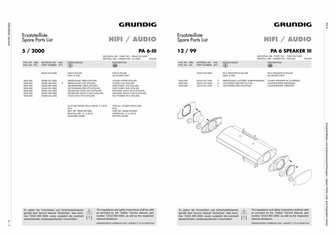
GR
UN
DIG
Service
4 - 7
PA
6E
rsatzteillisten und Explosionszeichnungen / S
pare Parts Lists and E
xploded View
s
ErsatzteillisteSpare Parts List
PA 6-III
HIFI / AUDIO
MATERIAL-NR. / PART NO.: 95540 312 5200BESTELL-NR. / ORDER NO.: GLI1950 POLAR
1
5 / 2000
POS. NR. ABB. MATERIAL-NR. ANZ. BEZEICHNUNG DESCRIPTIONPOS. NO. FIG. PART NUMBER QTY. d ©
95540 312 5200 PA6-III POLAR PA6-III POLARKEIN E-TEIL NO SPARE PART
0002.000 55398 201 0300 ABDECKUNG OBEN (POLAR) COVER UPPER (POLAR)0005.000 55398 298 0300 8 ABDECKUNG CLIP (POLAR) COVER CLIP (POLAR)0007.000 55403 500 0300 SEITENWAND LINKS (POLAR) SIDE PANEL LHS (POLAR)0008.000 55403 501 0300 SEITENWAND RECHTS (POLAR) SIDE PANEL RHS (POLAR)0020.000 55403 202 0300 GEHAEUSE CD/CF KEYS (POLAR) HOUSING CD/CF KEYS (POLAR)0024.000 55403 206 0300 GEHAEUSE SELECT KEYS (POLAR) HOUSING SELECT KEYS (POLAR)0029.000 55398 210 1300 TASTE NETZ PA 6 (POLAR) KEY POWER PA 6 (POLAR)
ALLE WEITEREN TEILE SIEHE E-LISTE FOR ALL OTHER PARTS SEEPA 6 PA 6MAT.-NR.: 95540 310 5000 PART NO.: 95540 310 5000BESTELL-NR.: G. LI 16-51 ORDER NO.: G. LI 16-51AUSGABE 5/2000 EDITION 5/2000
ÄNDERUNGEN VORBEHALTEN / SUBJECT TO ALTERATION
( ! )!Es gelten die Vorschriften und Sicherheitshinweise
gemäß dem Service Manual "Sicherheit", Mat.-Num-mer 72010 800 0000, sowie zusätzlich die eventuellabweichenden, landesspezifischen Vorschriften!
The regulations and safety instructions shall be validas provided by the "Safety" Service Manual, partnumber 72010 800 0000, as well as the respectivenational deviations.
ErsatzteillisteSpare Parts List
PA 6 SPEAKER III
HIFI / AUDIO
MATERIAL-NR. / PART NO.: 75202 910 5000BESTELL-NR. / ORDER NO.: GNI1150 POLAR
1
12 / 99
POS. NR. ABB. MATERIAL-NR. ANZ. BEZEICHNUNG DESCRIPTIONPOS. NO. FIG. PART NUMBER QTY. d ©
75202 910 5000 PA 6 SPEAKER III POLAR PA 6 SPEAKER III POLARKEIN E-TEIL NO SPARE PART
0010.000 51020 210 7300 2 ABDECKUNG LAUTSPR. M.BESPANNUNG COVER SPEAKER W.COVERING0020.000 19144 121 6100 2 LAUTSPRECHER MITTELTON LOUDSPEAKER MIDRANGE0030.000 19115 011 4700 2 LAUTSPRECHER HOCHTON LOUDSPEAKER TWEETER
ÄNDERUNGEN VORBEHALTEN / SUBJECT TO ALTERATION
( ! )!Es gelten die Vorschriften und Sicherheitshinweise
gemäß dem Service Manual "Sicherheit", Mat.-Num-mer 72010 800 0000, sowie zusätzlich die eventuellabweichenden, landesspezifischen Vorschriften!
The regulations and safety instructions shall be validas provided by the "Safety" Service Manual, partnumber 72010 800 0000, as well as the respectivenational deviations.
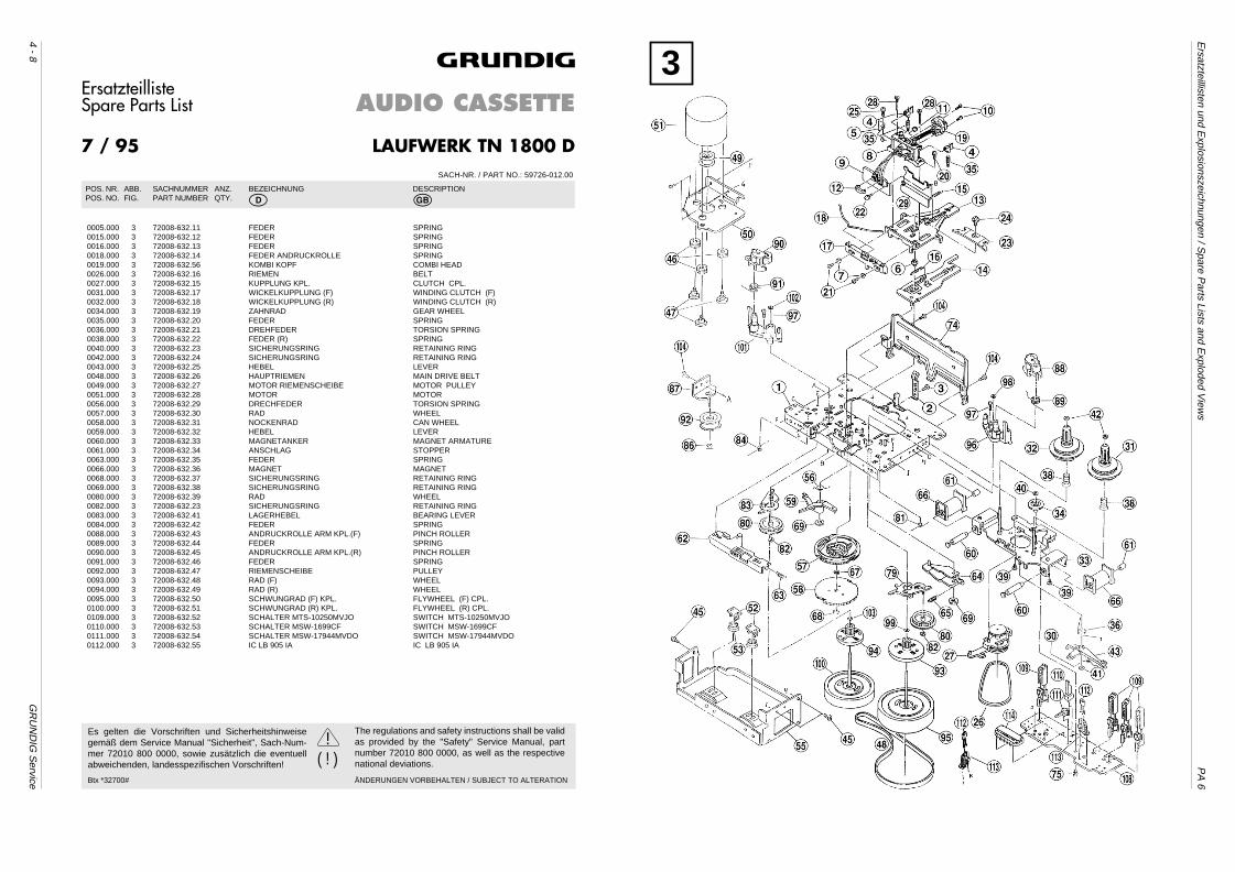
4 - 8G
RU
ND
IG S
ervice
Ersatzteillisten und E
xplosionszeichnungen / Spare P
arts Lists and Exploded V
iews
PA
6
ErsatzteillisteSpare Parts List
LAUFWERK TN 1800 D
AUDIO CASSETTE
SACH-NR. / PART NO.: 59726-012.00
1
7 / 95
POS. NR. ABB. SACHNUMMER ANZ. BEZEICHNUNG DESCRIPTIONPOS. NO. FIG. PART NUMBER QTY. d ©
0005.000 3 72008-632.11 FEDER SPRING0015.000 3 72008-632.12 FEDER SPRING0016.000 3 72008-632.13 FEDER SPRING0018.000 3 72008-632.14 FEDER ANDRUCKROLLE SPRING0019.000 3 72008-632.56 KOMBI KOPF COMBI HEAD0026.000 3 72008-632.16 RIEMEN BELT0027.000 3 72008-632.15 KUPPLUNG KPL. CLUTCH CPL.0031.000 3 72008-632.17 WICKELKUPPLUNG (F) WINDING CLUTCH (F)0032.000 3 72008-632.18 WICKELKUPPLUNG (R) WINDING CLUTCH (R)0034.000 3 72008-632.19 ZAHNRAD GEAR WHEEL0035.000 3 72008-632.20 FEDER SPRING0036.000 3 72008-632.21 DREHFEDER TORSION SPRING0038.000 3 72008-632.22 FEDER (R) SPRING0040.000 3 72008-632.23 SICHERUNGSRING RETAINING RING0042.000 3 72008-632.24 SICHERUNGSRING RETAINING RING0043.000 3 72008-632.25 HEBEL LEVER0048.000 3 72008-632.26 HAUPTRIEMEN MAIN DRIVE BELT0049.000 3 72008-632.27 MOTOR RIEMENSCHEIBE MOTOR PULLEY0051.000 3 72008-632.28 MOTOR MOTOR0056.000 3 72008-632.29 DRECHFEDER TORSION SPRING0057.000 3 72008-632.30 RAD WHEEL0058.000 3 72008-632.31 NOCKENRAD CAN WHEEL0059.000 3 72008-632.32 HEBEL LEVER0060.000 3 72008-632.33 MAGNETANKER MAGNET ARMATURE0061.000 3 72008-632.34 ANSCHLAG STOPPER0063.000 3 72008-632.35 FEDER SPRING0066.000 3 72008-632.36 MAGNET MAGNET0068.000 3 72008-632.37 SICHERUNGSRING RETAINING RING0069.000 3 72008-632.38 SICHERUNGSRING RETAINING RING0080.000 3 72008-632.39 RAD WHEEL0082.000 3 72008-632.23 SICHERUNGSRING RETAINING RING0083.000 3 72008-632.41 LAGERHEBEL BEARING LEVER0084.000 3 72008-632.42 FEDER SPRING0088.000 3 72008-632.43 ANDRUCKROLLE ARM KPL.(F) PINCH ROLLER0089.000 3 72008-632.44 FEDER SPRING0090.000 3 72008-632.45 ANDRUCKROLLE ARM KPL.(R) PINCH ROLLER0091.000 3 72008-632.46 FEDER SPRING0092.000 3 72008-632.47 RIEMENSCHEIBE PULLEY0093.000 3 72008-632.48 RAD (F) WHEEL0094.000 3 72008-632.49 RAD (R) WHEEL0095.000 3 72008-632.50 SCHWUNGRAD (F) KPL. FLYWHEEL (F) CPL.0100.000 3 72008-632.51 SCHWUNGRAD (R) KPL. FLYWHEEL (R) CPL.0109.000 3 72008-632.52 SCHALTER MTS-10250MVJO SWITCH MTS-10250MVJO0110.000 3 72008-632.53 SCHALTER MSW-1699CF SWITCH MSW-1699CF0111.000 3 72008-632.54 SCHALTER MSW-17944MVDO SWITCH MSW-17944MVDO0112.000 3 72008-632.55 IC LB 905 IA IC LB 905 IA
Btx *32700# ÄNDERUNGEN VORBEHALTEN / SUBJECT TO ALTERATION
( ! )!Es gelten die Vorschriften und Sicherheitshinweise
gemäß dem Service Manual "Sicherheit", Sach-Num-mer 72010 800 0000, sowie zusätzlich die eventuellabweichenden, landesspezifischen Vorschriften!
The regulations and safety instructions shall be validas provided by the "Safety" Service Manual, partnumber 72010 800 0000, as well as the respectivenational deviations.
3