high availability on the risc system/6000 family october · pdf file3.2 high availability...
TRANSCRIPT

International Technical Support Organization
High Availability on the RISC System/6000 Family
October 1995
SG24-4551-00


International Technical Support Organization
High Availability on the RISC System/6000 Family
October 1995
SG24-4551-00
IBML

Take Note!
Before using this information and the product it supports, be sure to read the general information under“Special Notices” on page xiii.
First Edition (October 1995)
This edition applies to Version 3.1 of HACMP/6000, Program Number 5696-923 for use with the AIX/6000 Version3.2.5 Operating System and Version 4.1 of HACMP for AIX, Program Number 5696-933 for use with the AIX Version4.1 Operating System.
Order publications through your IBM representative or the IBM branch office serving your locality. Publicationsare not stocked at the address given below.
An ITSO Technical Bulletin Evaluation Form for reader ′s feedback appears facing Chapter 1. If the form has beenremoved, comments may be addressed to:
IBM Corporation, International Technical Support OrganizationDept. JN9B Building 821 Internal Zip 283411400 Burnet RoadAustin, Texas 78758-3493
When you send information to IBM, you grant IBM a non-exclusive right to use or distribute the information in anyway it believes appropriate without incurring any obligation to you.
Copyright International Business Machines Corporation 1995. All rights reserved.Note to U.S. Government Users — Documentation related to restricted rights — Use, duplication or disclosure issubject to restrictions set forth in GSA ADP Schedule Contract with IBM Corp.

Abstract
This document is created for those who wish to implement a highly available AIXenvironment, using the HACMP for AIX product. It includes information on howto use standard AIX operating system facilities to enhance the availability of asingle system, and also describes how to set up an HACMP cluster. Thedocument also provides many helpful hints and tips to make yourimplementation easier. Some knowledge of the AIX operating system isassumed.
This document obsoletes and replaces the document ″High AvailabilityStrategies for AIX″ (order number GG24-3684).
(241 pages)
Copyright IBM Corp. 1995 iii

iv High Availability on the RISC System/6000 Family

Contents
Abstract . . . . . . . . . . . . . . . . . . . . . . . . . . . . . . . . . . . . . . . . . . i i i
Special Notices . . . . . . . . . . . . . . . . . . . . . . . . . . . . . . . . . . . . . xii i
Preface . . . . . . . . . . . . . . . . . . . . . . . . . . . . . . . . . . . . . . . . . . xvHow This Document is Organized . . . . . . . . . . . . . . . . . . . . . . . . . . xvRelated Publications . . . . . . . . . . . . . . . . . . . . . . . . . . . . . . . . . xviInternational Technical Support Organization Publications . . . . . . . . . . . xviITSO Redbooks on the World Wide Web (WWW) . . . . . . . . . . . . . . . . . xviiAcknowledgments . . . . . . . . . . . . . . . . . . . . . . . . . . . . . . . . . . . xvii
Chapter 1. Introduction to High Availability . . . . . . . . . . . . . . . . . . . . . 11.1 Introduction to Availability . . . . . . . . . . . . . . . . . . . . . . . . . . . . 1
1.1.1 Why is Availability Important? . . . . . . . . . . . . . . . . . . . . . . . . 21.2 Levels of Availability . . . . . . . . . . . . . . . . . . . . . . . . . . . . . . . . 3
1.2.1 Availabil ity Continuum . . . . . . . . . . . . . . . . . . . . . . . . . . . . 61.3 Key Threats to System Availability . . . . . . . . . . . . . . . . . . . . . . . 61.4 Availabil i ty Measurements . . . . . . . . . . . . . . . . . . . . . . . . . . . . 71.5 Availability as a Total System Concept . . . . . . . . . . . . . . . . . . . . . 8
1.5.1 Failure Rate and Availability . . . . . . . . . . . . . . . . . . . . . . . . 9
Chapter 2. Single System Availability . . . . . . . . . . . . . . . . . . . . . . . . 112.1 Availability Features of AIX . . . . . . . . . . . . . . . . . . . . . . . . . . . . 11
2.1.1 System Management Interface Tool (SMIT) . . . . . . . . . . . . . . . . 112.1.2 Logical Volume Manager (LVM) . . . . . . . . . . . . . . . . . . . . . . 112.1.3 Journaled Filesystem (JFS) . . . . . . . . . . . . . . . . . . . . . . . . . 122.1.4 Dynamic AIX Kernel . . . . . . . . . . . . . . . . . . . . . . . . . . . . . 122.1.5 System Resource Controller (SRC) . . . . . . . . . . . . . . . . . . . . 132.1.6 Configuration Manager . . . . . . . . . . . . . . . . . . . . . . . . . . . . 132.1.7 AIX Update Facilities . . . . . . . . . . . . . . . . . . . . . . . . . . . . . 13
2.2 Availability Features of the RISC System/6000 . . . . . . . . . . . . . . . . 132.2.1 Built-In Error Detection and Correction . . . . . . . . . . . . . . . . . . 132.2.2 Backup Power Supply . . . . . . . . . . . . . . . . . . . . . . . . . . . . 142.2.3 Power Conditioning . . . . . . . . . . . . . . . . . . . . . . . . . . . . . . 142.2.4 Redundant or Spare Disks . . . . . . . . . . . . . . . . . . . . . . . . . . 152.2.5 Hot Pluggable Disk Drives . . . . . . . . . . . . . . . . . . . . . . . . . . 152.2.6 Multi-Tailed Disks and Shared Volume Groups . . . . . . . . . . . . . 152.2.7 RAID Disk Arrays . . . . . . . . . . . . . . . . . . . . . . . . . . . . . . . 15
2.3 Improved Availability Through System Management Practices . . . . . . 192.3.1 Skills Management . . . . . . . . . . . . . . . . . . . . . . . . . . . . . . 202.3.2 Operations Management . . . . . . . . . . . . . . . . . . . . . . . . . . . 202.3.3 Capacity Management . . . . . . . . . . . . . . . . . . . . . . . . . . . . 202.3.4 Change Management . . . . . . . . . . . . . . . . . . . . . . . . . . . . . 212.3.5 System Test Environment . . . . . . . . . . . . . . . . . . . . . . . . . . 212.3.6 Performance Management . . . . . . . . . . . . . . . . . . . . . . . . . 222.3.7 Problem Management . . . . . . . . . . . . . . . . . . . . . . . . . . . . 222.3.8 Service Level Management . . . . . . . . . . . . . . . . . . . . . . . . . 222.3.9 Automated Operations . . . . . . . . . . . . . . . . . . . . . . . . . . . . 22
2.4 Isolation . . . . . . . . . . . . . . . . . . . . . . . . . . . . . . . . . . . . . . . 232.4.1 Recovery Management . . . . . . . . . . . . . . . . . . . . . . . . . . . . 23
2.5 Summary . . . . . . . . . . . . . . . . . . . . . . . . . . . . . . . . . . . . . . . 24
Copyright IBM Corp. 1995 v

Chapter 3. Clustering RISC System/6000s for High Availability . . . . . . . . . 253.1 An Introduction to Clustering . . . . . . . . . . . . . . . . . . . . . . . . . . . 25
3.1.1 What Is a Cluster? . . . . . . . . . . . . . . . . . . . . . . . . . . . . . . . 253.1.2 Single Points of Failure . . . . . . . . . . . . . . . . . . . . . . . . . . . . 263.1.3 Eliminating Single Points of Failure in a Cluster . . . . . . . . . . . . . 263.1.4 Disadvantages of Manual Intervention . . . . . . . . . . . . . . . . . . . 28
3.2 High Availability Cluster Multi-Processing/6000 . . . . . . . . . . . . . . . . 283.2.1 HACMP Technical Overview . . . . . . . . . . . . . . . . . . . . . . . . . 293.2.2 HACMP Cluster Components . . . . . . . . . . . . . . . . . . . . . . . . 303.2.3 HACMP Cluster Resources . . . . . . . . . . . . . . . . . . . . . . . . . 423.2.4 HACMP Cluster Configurations . . . . . . . . . . . . . . . . . . . . . . . 453.2.5 HACMP Cluster Events . . . . . . . . . . . . . . . . . . . . . . . . . . . . 493.2.6 Clients in an HACMP Cluster . . . . . . . . . . . . . . . . . . . . . . . . 55
3.3 Conclusion . . . . . . . . . . . . . . . . . . . . . . . . . . . . . . . . . . . . . . 57
Chapter 4. Hardware Options for HACMP . . . . . . . . . . . . . . . . . . . . . . 594.1 CPU Options . . . . . . . . . . . . . . . . . . . . . . . . . . . . . . . . . . . . . 594.2 How to Select CPU Nodes for Your Cluster . . . . . . . . . . . . . . . . . . 60
4.2.1 Node Configuration Guidelines . . . . . . . . . . . . . . . . . . . . . . . 614.3 Storage Options . . . . . . . . . . . . . . . . . . . . . . . . . . . . . . . . . . . 63
4.3.1 SCSI Technologies . . . . . . . . . . . . . . . . . . . . . . . . . . . . . . 634.3.2 Conventional SCSI Disk Options . . . . . . . . . . . . . . . . . . . . . . 654.3.3 RAID Disk Array Features . . . . . . . . . . . . . . . . . . . . . . . . . . 674.3.4 RAID Disk Array Options . . . . . . . . . . . . . . . . . . . . . . . . . . . 684.3.5 Serial/SSA Disk Storage . . . . . . . . . . . . . . . . . . . . . . . . . . . 704.3.6 Choosing a Shared Disk Technology . . . . . . . . . . . . . . . . . . . 75
4.4 Connectivity Options . . . . . . . . . . . . . . . . . . . . . . . . . . . . . . . . 774.4.1 TCP/IP Networks . . . . . . . . . . . . . . . . . . . . . . . . . . . . . . . 784.4.2 Choosing a Network for Your Cluster . . . . . . . . . . . . . . . . . . . 794.4.3 Non-TCP/IP Networks . . . . . . . . . . . . . . . . . . . . . . . . . . . . . 80
Chapter 5. Setting Up HACMP for AIX . . . . . . . . . . . . . . . . . . . . . . . . 815.1 Installing and Configuring HACMP/6000 Version 3.1 . . . . . . . . . . . . . 835.2 Preparing AIX for an HACMP Cluster . . . . . . . . . . . . . . . . . . . . . . 83
5.2.1 Configuring IP Networks . . . . . . . . . . . . . . . . . . . . . . . . . . . 845.2.2 Installing Shared SCSI Disks . . . . . . . . . . . . . . . . . . . . . . . . 905.2.3 Defining Shared LVM Components . . . . . . . . . . . . . . . . . . . . . 945.2.4 Additional Tasks . . . . . . . . . . . . . . . . . . . . . . . . . . . . . . . 100
5.3 Setting Up a New HACMP Cluster . . . . . . . . . . . . . . . . . . . . . . . 1025.3.1 Installation Prerequisites . . . . . . . . . . . . . . . . . . . . . . . . . . 1025.3.2 Installation Options . . . . . . . . . . . . . . . . . . . . . . . . . . . . . 1025.3.3 Installing the HACMP Software on Node 1 and Node 2 . . . . . . . . 1025.3.4 Installing the HACMP Client Portion on Client Systems . . . . . . . 1035.3.5 Rebooting Nodes and Clients . . . . . . . . . . . . . . . . . . . . . . . 1055.3.6 Verifying the Cluster Software . . . . . . . . . . . . . . . . . . . . . . 1055.3.7 Defining the Cluster Environment . . . . . . . . . . . . . . . . . . . . 1085.3.8 Defining Application Servers . . . . . . . . . . . . . . . . . . . . . . . 1195.3.9 Creating Resource Groups . . . . . . . . . . . . . . . . . . . . . . . . 1205.3.10 Verify Cluster Environment . . . . . . . . . . . . . . . . . . . . . . . . 1285.3.11 Starting Cluster Services . . . . . . . . . . . . . . . . . . . . . . . . . 129
5.4 Upgrading a Cluster to HACMP/6000 Version 3.1 . . . . . . . . . . . . . . 1315.4.1 Prerequisites for Upgrade . . . . . . . . . . . . . . . . . . . . . . . . . 1365.4.2 Preparing the Cluster for the Upgrade . . . . . . . . . . . . . . . . . 1365.4.3 Installing the HACMP/6000 Version 3.1 Software . . . . . . . . . . . 1395.4.4 Upgrading from Version 2.1 to Version 3.1 . . . . . . . . . . . . . . . 140
vi High Availability on the RISC System/6000 Family

5.4.5 Further Tasks . . . . . . . . . . . . . . . . . . . . . . . . . . . . . . . . 1455.4.6 Verification . . . . . . . . . . . . . . . . . . . . . . . . . . . . . . . . . . 155
5.5 Upgrading a Cluster from HACMP/6000 Version 3.1 . . . . . . . . . . . . 157
Chapter 6. Cluster Tuning and Customization . . . . . . . . . . . . . . . . . . 1596.1 When is Cluster Tuning Required . . . . . . . . . . . . . . . . . . . . . . . 1596.2 False Takeover . . . . . . . . . . . . . . . . . . . . . . . . . . . . . . . . . . 1606.3 The Deadman Switch . . . . . . . . . . . . . . . . . . . . . . . . . . . . . . 1606.4 Tuning System I/O . . . . . . . . . . . . . . . . . . . . . . . . . . . . . . . . 162
6.4.1 I/O Pacing . . . . . . . . . . . . . . . . . . . . . . . . . . . . . . . . . . 1626.4.2 sync Daemon (syncd) . . . . . . . . . . . . . . . . . . . . . . . . . . . . 1646.4.3 Disabling the Deadman Switch . . . . . . . . . . . . . . . . . . . . . . 165
6.5 Cluster Manager Startup Parameters . . . . . . . . . . . . . . . . . . . . . 1666.5.1 HACMP/6000 Version 2.1 . . . . . . . . . . . . . . . . . . . . . . . . . . 1666.5.2 HACMP/6000 Version 3.1 . . . . . . . . . . . . . . . . . . . . . . . . . . 1686.5.3 Pinning the Cluster Manager . . . . . . . . . . . . . . . . . . . . . . . 171
6.6 HACMP Cluster Customization Examples . . . . . . . . . . . . . . . . . . 1716.7 Pre-Event and Post-Event Script Parameters . . . . . . . . . . . . . . . . 1726.8 AIX Error Notification . . . . . . . . . . . . . . . . . . . . . . . . . . . . . . . 172
Chapter 7. Tips and Techniques . . . . . . . . . . . . . . . . . . . . . . . . . . 1757.1 Change Management . . . . . . . . . . . . . . . . . . . . . . . . . . . . . . 175
7.1.1 Cluster Verification . . . . . . . . . . . . . . . . . . . . . . . . . . . . . 1767.1.2 Software Upgrades and Fixes . . . . . . . . . . . . . . . . . . . . . . . 1767.1.3 Cluster Maintenance - Do′s and Dont′s . . . . . . . . . . . . . . . . . 1797.1.4 Requirement for Additional Filesystems . . . . . . . . . . . . . . . . . 1797.1.5 Requirement for New Applications . . . . . . . . . . . . . . . . . . . . 1807.1.6 Requirement for New Communications Connectivity . . . . . . . . . 180
7.2 Mirroring the Root Volume Group (rootvg) . . . . . . . . . . . . . . . . . . 1807.2.1 Solution . . . . . . . . . . . . . . . . . . . . . . . . . . . . . . . . . . . . 1817.2.2 Procedure . . . . . . . . . . . . . . . . . . . . . . . . . . . . . . . . . . 1827.2.3 Testing Your Configuration . . . . . . . . . . . . . . . . . . . . . . . . 184
7.3 Quorum . . . . . . . . . . . . . . . . . . . . . . . . . . . . . . . . . . . . . . . 1847.3.1 Quorum in Shared Disk Configurations . . . . . . . . . . . . . . . . . 186
7.4 /etc/filesystems and the jfslog . . . . . . . . . . . . . . . . . . . . . . . . . 1867.5 Filesystem Helper . . . . . . . . . . . . . . . . . . . . . . . . . . . . . . . . 1887.6 Phantom Disks . . . . . . . . . . . . . . . . . . . . . . . . . . . . . . . . . . 1897.7 /etc/inittab File . . . . . . . . . . . . . . . . . . . . . . . . . . . . . . . . . . 1907.8 Permissions on the /tmp Directory . . . . . . . . . . . . . . . . . . . . . . 1917.9 ARP Cache . . . . . . . . . . . . . . . . . . . . . . . . . . . . . . . . . . . . 1917.10 Synchronizing Time Between Cluster Nodes . . . . . . . . . . . . . . . . 1927.11 Tips on Writing Application Server and Event Scripts . . . . . . . . . . 193
7.11.1 Problem for HACMP/6000 Version 3.1 Users Before PTF U438726 . 1937.12 Recovery From Event Script Failure . . . . . . . . . . . . . . . . . . . . . 1957.13 AIX Error Notification . . . . . . . . . . . . . . . . . . . . . . . . . . . . . . 1957.14 7135 RAIDiant Disk Array . . . . . . . . . . . . . . . . . . . . . . . . . . . 1957.15 Resource Group Organization . . . . . . . . . . . . . . . . . . . . . . . . 1967.16 Hubs in an HACMP Cluster . . . . . . . . . . . . . . . . . . . . . . . . . . 197
Appendix A. HACMP Software Components . . . . . . . . . . . . . . . . . . . 199A.1 Cluster Manager . . . . . . . . . . . . . . . . . . . . . . . . . . . . . . . . . 199
A.1.1 Cluster Controller . . . . . . . . . . . . . . . . . . . . . . . . . . . . . . 200A.1.2 Network Interface Layer . . . . . . . . . . . . . . . . . . . . . . . . . . 201A.1.3 Network Interface Modules . . . . . . . . . . . . . . . . . . . . . . . . 202A.1.4 Event Manager . . . . . . . . . . . . . . . . . . . . . . . . . . . . . . . 203
Contents vii

A.2 Cluster SMUX Peer and Cluster Information Services . . . . . . . . . . . 203A.3 Cluster Lock Manager . . . . . . . . . . . . . . . . . . . . . . . . . . . . . . 204
A.3.1 UNIX System V Locking Model . . . . . . . . . . . . . . . . . . . . . . 204A.3.2 CLM Locking Model . . . . . . . . . . . . . . . . . . . . . . . . . . . . 205A.3.3 Lock Management . . . . . . . . . . . . . . . . . . . . . . . . . . . . . 206
A.4 Interaction Between the HACMP Software Components . . . . . . . . . 206
Appendix B. Disk Setup in an HACMP Cluster . . . . . . . . . . . . . . . . . . 209B.1 SCSI Disks and Subsystems . . . . . . . . . . . . . . . . . . . . . . . . . . 209
B.1.1 SCSI Adapters . . . . . . . . . . . . . . . . . . . . . . . . . . . . . . . . 209B.1.2 Individual Disks and Enclosures . . . . . . . . . . . . . . . . . . . . . 212B.1.3 Hooking It All Up . . . . . . . . . . . . . . . . . . . . . . . . . . . . . . 213B.1.4 AIX′s View of Shared SCSI Disks . . . . . . . . . . . . . . . . . . . . 218
B.2 RAID Subsystems . . . . . . . . . . . . . . . . . . . . . . . . . . . . . . . . 218B.2.1 SCSI Adapters . . . . . . . . . . . . . . . . . . . . . . . . . . . . . . . . 219B.2.2 RAID Enclosures . . . . . . . . . . . . . . . . . . . . . . . . . . . . . . 219B.2.3 Connecting RAID Subsystems . . . . . . . . . . . . . . . . . . . . . . 219B.2.4 AIX′s View of Shared RAID Devices . . . . . . . . . . . . . . . . . . . 223
B.3 Serial Disk Subsystems . . . . . . . . . . . . . . . . . . . . . . . . . . . . . 224B.3.1 High-Performance Disk Drive Subsystem Adapter . . . . . . . . . . 224B.3.2 9333 Disk Subsystems . . . . . . . . . . . . . . . . . . . . . . . . . . . 224B.3.3 Connecting Serial Disk Subsystems in an HACMP Cluster . . . . . 224B.3.4 AIX′s View of Shared Serial Disk Subsystems . . . . . . . . . . . . . 225
B.4 Serial Storage Architecture (SSA) Subsystems . . . . . . . . . . . . . . . 226B.4.1 SSA Software Requirements . . . . . . . . . . . . . . . . . . . . . . . 226B.4.2 SSA Four Port Adapter . . . . . . . . . . . . . . . . . . . . . . . . . . . 227B.4.3 IBM 7133 SSA Disk Subsystem . . . . . . . . . . . . . . . . . . . . . . 228B.4.4 SSA Cables . . . . . . . . . . . . . . . . . . . . . . . . . . . . . . . . . 229B.4.5 Connecting 7133 SSA Subsystems in an HACMP Cluster . . . . . . 230B.4.6 AIX′s View of Shared SSA Disk Subsystems . . . . . . . . . . . . . . 232
Appendix C. Measurements of Disk Reliability . . . . . . . . . . . . . . . . . . 233C.1 Mean Time Between Failure (MTBF) . . . . . . . . . . . . . . . . . . . . . 233
C.1.1 Defining Mean Time Between Failure . . . . . . . . . . . . . . . . . . 233C.1.2 Mean Time Between Failure and Actual Failures. . . . . . . . . . . 233C.1.3 Predicted Mean Time Between Failure . . . . . . . . . . . . . . . . . 234C.1.4 Comparison of MTBF Figures . . . . . . . . . . . . . . . . . . . . . . . 235
C.2 Cumulative Distribution Function (CDF) . . . . . . . . . . . . . . . . . . . 235
List of Abbreviations . . . . . . . . . . . . . . . . . . . . . . . . . . . . . . . . . 237
Index . . . . . . . . . . . . . . . . . . . . . . . . . . . . . . . . . . . . . . . . . . . 239
viii High Availability on the RISC System/6000 Family

Figures
1. Availabil ity Continuum . . . . . . . . . . . . . . . . . . . . . . . . . . . . . . 5 2. Availability is a System-Wide Consideration . . . . . . . . . . . . . . . . . 8 3. The RAID Concept . . . . . . . . . . . . . . . . . . . . . . . . . . . . . . . . 16 4. RAID-0 Illustration . . . . . . . . . . . . . . . . . . . . . . . . . . . . . . . . . 16 5. RAID-1 Illustration . . . . . . . . . . . . . . . . . . . . . . . . . . . . . . . . . 17 6. RAID-3 Illustration . . . . . . . . . . . . . . . . . . . . . . . . . . . . . . . . . 18 7. RAID-5 Illustration . . . . . . . . . . . . . . . . . . . . . . . . . . . . . . . . . 19 8. HACMP Cluster Example . . . . . . . . . . . . . . . . . . . . . . . . . . . . 31 9. Disk Takeover . . . . . . . . . . . . . . . . . . . . . . . . . . . . . . . . . . . 3910. IP Address Takeover . . . . . . . . . . . . . . . . . . . . . . . . . . . . . . . 4011. Adapter Swapping . . . . . . . . . . . . . . . . . . . . . . . . . . . . . . . . 4112. Cascading Resource Group . . . . . . . . . . . . . . . . . . . . . . . . . . . 4313. Rotating Resource Group . . . . . . . . . . . . . . . . . . . . . . . . . . . . 4414. Concurrent Resource Group . . . . . . . . . . . . . . . . . . . . . . . . . . 4515. Hot Standby Configuration . . . . . . . . . . . . . . . . . . . . . . . . . . . . 4616. Mutual Takeover Configuration . . . . . . . . . . . . . . . . . . . . . . . . . 4717. Third-Party Takeover Configuration . . . . . . . . . . . . . . . . . . . . . . 4818. First Node Joins Cluster . . . . . . . . . . . . . . . . . . . . . . . . . . . . . 5119. Node Joins an Active Cluster . . . . . . . . . . . . . . . . . . . . . . . . . . 5220. Node Fails . . . . . . . . . . . . . . . . . . . . . . . . . . . . . . . . . . . . . 5321. Node Leaves the Cluster Gracefully with Takeover . . . . . . . . . . . . . 5422. Flow of Execution of Event Scripts . . . . . . . . . . . . . . . . . . . . . . . 5623. Single-Ended (SE) and Differential-Ended (DE) SCSI . . . . . . . . . . . . 6424. 9334-501 Shared Between Two Deskside Systems . . . . . . . . . . . . . 6625. 9333 Serial Disk Drive Subsystem System Attachment . . . . . . . . . . . 7126. Four-Node Cluster with Shared 9333 Serial Disk Subsystem (Rear View) 7227. Typical SSA Loop Topology . . . . . . . . . . . . . . . . . . . . . . . . . . . 7328. SSA-Based High Availability Servers . . . . . . . . . . . . . . . . . . . . . 7429. Sample HACMP Cluster Configuration . . . . . . . . . . . . . . . . . . . . 8230. Alternative RS232 Serial Line Connection . . . . . . . . . . . . . . . . . . 8931. Defining Shared LVM Components for Non-Concurrent Access . . . . . 9532. Cluster Running HACMP/6000 Version 2.1 . . . . . . . . . . . . . . . . . 13233. HACMP/6000 Version 2.1 Cluster Configuration . . . . . . . . . . . . . . 13334. HACMP/6000 Version 2.1 Node Environment Configuration . . . . . . . 13535. Cluster Configuration After Upgrade from HACMP/6000 Version 2.1 . . 14236. Node 1′s Resources After Upgrade from HACMP/6000 Version 2.1 . . 14437. Cluster Configuration After Changes . . . . . . . . . . . . . . . . . . . . 14938. Node1 Resources After Changes . . . . . . . . . . . . . . . . . . . . . . . 15139. Node2 Resources After Changes . . . . . . . . . . . . . . . . . . . . . . . 15240. Cluster Verification Output After Changes . . . . . . . . . . . . . . . . . 15641. Applying Software Fixes, Part 1 . . . . . . . . . . . . . . . . . . . . . . . 17742. Applying Software Fixes, Part 2 . . . . . . . . . . . . . . . . . . . . . . . 17843. Volume Group Quorum . . . . . . . . . . . . . . . . . . . . . . . . . . . . 18544. Quorum for Shared Disks in HACMP Configurations . . . . . . . . . . . 18645. Phantom Disks . . . . . . . . . . . . . . . . . . . . . . . . . . . . . . . . . 18946. Protecting Your Network against Hub Failure . . . . . . . . . . . . . . . 19747. Cluster Manager Structure and Peer Connectivity in an HACMP Cluster 20048. Interaction Between the HACMP Software Components in a Cluster . 20749. Termination Resistor Blocks on the SCSI-2 Differential Controller . . . 21050. Termination Resistor Blocks on the SCSI-2 Differential Fast/Wide
Adapter/A and Enhanced SCSI-2 Differential Fast/Wide Adapter/A . . 210
Copyright IBM Corp. 1995 ix

51. 7204-215 External Disk Drives Connected on an 8-Bit Shared SCSI Bus 21352. 7204-315 External Disk Drives Connected on a 16-Bit Shared SCSI Bus 21453. 9334-011 SCSI Expansion Units Connected on an 8-Bit Shared SCSI
Bus . . . . . . . . . . . . . . . . . . . . . . . . . . . . . . . . . . . . . . . . 21654. 9334-501 SCSI Expansion Units Connected on an 8-Bit Shared SCSI
Bus . . . . . . . . . . . . . . . . . . . . . . . . . . . . . . . . . . . . . . . . 21655. 7134-010 High Density SCSI Disk Subsystem Connected on Two 16-Bit
Shared SCSI Buses . . . . . . . . . . . . . . . . . . . . . . . . . . . . . . . 21856. 7135-110 RAIDiant Arrays Connected on Two Shared 8-Bit SCSI Buses 22057. 7135-110 RAIDiant Arrays Connected on Two Shared 16-Bit SCSI Buses 22158. 7137 Disk Array Subsystems Connected on an 8-Bit SCSI Bus . . . . . 22259. 7137 Disk Array Subsystems Connected on a 16-Bit SCSI Bus . . . . . 22360. 9333-501 Connected to Eight Nodes in an HACMP Cluster (Rear View) 22561. SSA Four Port Aapter . . . . . . . . . . . . . . . . . . . . . . . . . . . . . 22762. IBM 7133 SSA Disk Subsystem . . . . . . . . . . . . . . . . . . . . . . . . 22863. High Availability SSA Cabling Scenario 1 . . . . . . . . . . . . . . . . . . 23064. High Availability SSA Cabling Scenario 2 . . . . . . . . . . . . . . . . . . 232
x High Availability on the RISC System/6000 Family

Tables
1. SCSI Adapter Characteristics . . . . . . . . . . . . . . . . . . . . . . . . . . 64 2. SCSI-2 External Disk Drive Enclosures . . . . . . . . . . . . . . . . . . . . 65 3. TCP/IP Network Types and Their Attributes . . . . . . . . . . . . . . . . . 78 4. Cluster Manager Startup Switches . . . . . . . . . . . . . . . . . . . . . . 166 5. Cluster Manager Failure Detection Rates . . . . . . . . . . . . . . . . . 169 6. Organization of Volume Group Descriptor Areas on Physical Disks . . 181 7. Mode Compatibility for CLM Locks . . . . . . . . . . . . . . . . . . . . . 205 8. Serial Storage Architecture (SSA) Cables . . . . . . . . . . . . . . . . . 229
Copyright IBM Corp. 1995 xi

xii High Availability on the RISC System/6000 Family

Special Notices
This publication is intended to help RISC System/6000 users to understand, planand configure a high availability solution for AIX. The information in thispublication is not intended as the specification of any programming interfacesthat are provided by High Availability Cluster Multi-Processing/6000 Version 3.1,HACMP 4.1 for AIX, or AIX Version 3.2.5 or 4.1. See the PUBLICATIONS sectionof the IBM Programming Announcements for AIX Version 3.2 and 4.1,HACMP/6000 Version 3.1, and HACMP 4.1 for AIX for more information aboutwhat publications are considered to be product documentation.
References in this publication to IBM products, programs or services do notimply that IBM intends to make these available in all countries in which IBMoperates. Any reference to an IBM product, program, or service is not intendedto state or imply that only IBM′s product, program, or service may be used. Anyfunctionally equivalent program that does not infringe any of IBM′s intellectualproperty rights may be used instead of the IBM product, program or service.
Information in this book was developed in conjunction with use of the equipmentspecified, and is limited in application to those specific hardware and softwareproducts and levels.
IBM may have patents or pending patent applications covering subject matter inthis document. The furnishing of this document does not give you any license tothese patents. You can send license inquiries, in writing, to the IBM Director ofLicensing, IBM Corporation, 500 Columbus Avenue, Thornwood, NY 10594 USA.
The information contained in this document has not been submitted to anyformal IBM test and is distributed AS IS. The information about non-IBM(VENDOR) products in this manual has been supplied by the vendor and IBMassumes no responsibility for its accuracy or completeness. The use of thisinformation or the implementation of any of these techniques is a customerresponsibility and depends on the customer′s ability to evaluate and integratethem into the customer′s operational environment. While each item may havebeen reviewed by IBM for accuracy in a specific situation, there is no guaranteethat the same or similar results will be obtained elsewhere. Customersattempting to adapt these techniques to their own environments do so at theirown risk.
Reference to PTF numbers that have not been released through the normaldistribution process does not imply general availability. The purpose ofincluding these reference numbers is to alert IBM customers to specificinformation relative to the implementation of the PTF when it becomes availableto each customer according to the normal IBM PTF distribution process.
The following terms are trademarks of the International Business MachinesCorporation in the United States and/or other countries:
AIXAIX/6000IBMInfoExplorerMicro ChannelNetView
Copyright IBM Corp. 1995 xiii

POWERserverRISC System/6000RS/6000
The following terms in this publication are trademarks of other companies:
C-bus is a trademark of Corollary, Inc.Network File System and NFS are trademarks of SUN Microsystems, Inc.PC Direct is a trademark of Ziff Communications Company and isused by IBM Corporation under license.SUN Microsystems is a trademark of SUN Microsystems, Inc.UNIX is a registered trademark in the United States and other
countries licensed exclusively through X/Open Company Limited.Windows is a trademark of Microsoft Corporation
Other trademarks are trademarks of their respective companies.
xiv High Availability on the RISC System/6000 Family

Preface
This document is created for those who wish to implement a highly available AIXenvironment, using the HACMP for AIX product. It includes information on howto use standard AIX operating system facilities to enhance the availability of asingle system, and also describes how to set up an HACMP cluster. Thedocument also provides many helpful hints and tips to make yourimplementation easier.
This document was written for anyone investigating or planning a highlyavailable AIX environment. Some knowledge of the AIX operating system isassumed.
This document obsoletes and replaces the document ″High AvailabilityStrategies for AIX″ (order number GG24-3684).
How This Document is OrganizedThe document is organized as follows:
• Chapter 1, “Introduction to High Availability”
This chapter introduces availability concepts, including basic terminology,levels of availability, and various measurements of availability.
• Chapter 2, “Single System Availability”
This chapter covers the AIX and RS/6000 features that can be exploited toincrease the availability of a single AIX system. It also describes systemmanagement disciplines that are essential in maintaining a highly availablesystem.
• Chapter 3, “Clustering RISC System/6000s for High Availability”
This chapter introduces the concept of clustering RISC System/6000s forhigher availability. It goes on to introduce the concepts and capabilities ofthe HACMP product.
• Chapter 4, “Hardware Options for HACMP”
This chapter introduces the hardware options available in configuring yourcluster, in terms of CPU, shared disk, and communications facilities. It alsoprovides guidance on how to decide among the options available.
• Chapter 5, “Setting Up HACMP for AIX”
This chapter describes how to install and set up an HACMP cluster. It alsogives instruction on upgrading your cluster from a previous version of theHACMP product.
• Chapter 6, “Cluster Tuning and Customization”
This chapter describes how to tune your cluster to avoid false takeoverevents, and how to customize the cluster manager behavior and eventprocessing to suit your requirements. It also includes information on usingthe Error Notification facility of HACMP.
• Chapter 7, “Tips and Techniques”
This chapter provides a number of tips and techniques, to allow smootherinstallation, setup, and adminstration of an AIX cluster.
Copyright IBM Corp. 1995 xv

• Appendix A, “HACMP Software Components”
This appendix gives a description of the major software components ofHACMP, and how they interact.
• Appendix B, “Disk Setup in an HACMP Cluster”
This appendix gives a detailed description of adapter and cablingrequirements for all the types of shared disk supported under HACMP.
• Appendix C, “Measurements of Disk Reliability”
This appendix describes the concept of Mean Time Between Failure.
Related PublicationsThe publications listed in this section are considered particularly suitable for amore detailed discussion of the topics covered in this document.
HACMP/6000 Version 3.1
• HACMP/6000 Concepts and Facilities, SC23-2699
• HACMP/6000 Planning Guide, SC23-2700
• HACMP/6000 Installation Guide, SC23-2701
• HACMP/6000 Administration Guide, SC23-2702
• HACMP/6000 Troubleshooting Guide, SC23-2703
• HACMP/6000 Programming Locking Applications, SC23-2704
• HACMP/6000 Programming Client Applications, SC23-2705
• HACMP/6000 Master Index and Glossary, SC23-2707
• HACMP/6000 Licensed Program Specification, GC23-2698
HACMP 4.1 for AIX
• HACMP 4.1 for AIX: Concepts and Facilities, SC23-2767
• HACMP 4.1 for AIX: Planning Guide, SC23-2768
• HACMP 4.1 for AIX: Installation Guide, SC23-2769
• HACMP 4.1 for AIX: Administration Guide, SC23-2770
• HACMP 4.1 for AIX: Troubleshooting Guide, SC23-2771
• HACMP 4.1 for AIX: Programming Locking Applications, SC23-2772
• HACMP 4.1 for AIX: Programming Client Applications, SC23-2773
• HACMP 4.1 for AIX: Master Index and Glossary, SC23-2774
• HACMP 4.1 for AIX: Licensed Program Specification, GC23-2766
International Technical Support Organization Publications• HACMP/6000 Customization Examples, SG24-4498
• HACMP/6000 Mode 3 Implementation, GG24-3685
A complete list of International Technical Support Organization publications,known as redbooks, with a brief description of each, may be found in:
xvi High Availability on the RISC System/6000 Family

International Technical Support Organization Bibliography of Redbooks,GG24-3070.
To get a catalog of ITSO redbooks, VNET users may type:
TOOLS SENDTO WTSCPOK TOOLS REDBOOKS GET REDBOOKS CATALOG
A listing of all redbooks, sorted by category, may also be found on MKTTOOLSas ITSOCAT TXT. This package is updated monthly.
How to Order ITSO Redbooks
IBM employees in the USA may order ITSO books and CD-ROMs usingPUBORDER. Customers in the USA may order by calling 1-800-879-2755 or byfaxing 1-800-284-4721. Visa and Master Cards are accepted. Outside theUSA, customers should contact their local IBM office. For guidance onordering, send a PROFS note to BOOKSHOP at DKIBMVM1 or email [email protected].
Customers may order hardcopy ITSO books individually or in customizedsets, called BOFs, which relate to specific functions of interest. IBMemployees and customers may also order ITSO books in online format onCD-ROM collections, which contain redbooks on a variety of products.
ITSO Redbooks on the World Wide Web (WWW)Internet users may find information about redbooks on the ITSO World Wide Webhome page. To access the ITSO Web pages, point your Web browser to thefollowing URL:
http://www.redbooks.ibm.com/redbooks
IBM employees may access LIST3820s of redbooks as well. The internalRedbooks home page may be found at the following URL:
http://w3.itsc.pok.ibm.com/redbooks/redbooks.html
AcknowledgmentsThis project was designed and managed by:
David ThiessenInternational Technical Support Organization, Austin Center
The authors of this document are:
Andrew BeyerIBM Australia
Rahul BhattacharyaTata Information Systems Ltd. (India)An IBM and Tata Company
This document is an update and replacement for the document ″High AvailabilityStrategies for AIX″ (GG24-3684).
Preface xvii

The authors of the previous document were:
Mark WatsonIBM United Kingdom
Charlotte BrooksIBM Australia
Bell ChangIBM Taiwan
Ronald DaemsIBM Belgium
Miguel CrisantoIBM Germany
John EastonIBM United Kingdom
The advisors for the previous document were:
David ThiessenInternational Technical Support Organization, Austin Center
Mark JohnsonIBM Australia
This publication is the result of a residency conducted at the InternationalTechnical Support Organization, Austin Center.
Thanks to the following people for the invaluable advice and guidance providedin the production of this document:
Marcus BrewerInternational Technical Support Organization, Austin Center
Laurene JacobInternational Technical Support Organization, Austin Center
Cindy BarrettIBM Austin
Tom WeaverIBM Austin
Nadim TabassumIBM France
xviii High Availability on the RISC System/6000 Family

Chapter 1. Introduction to High Availability
When an organization purchases a new computer system, it is investingresources, both financial and human, in a new asset. This new asset will, likeany other asset, require care and attention to provide its maximum return. Akey attribute that influences the level of return that a system can provide is itslevel of availability. Availability is simply the proportion of the time that asystem is able to be used for its intended purpose.
Availability has become a significant issue for many companies today. Withcomputerized applications becoming more critical to business operations, theextent to which companies rely on their computer systems, has never beengreater. The amount of availability a system provides is dependent on a rangeof issues. This book is an update to the publication entitled High AvailabilityStrategies for AIX. It builds on the concepts and practices covered in theprevious edition with new and updated information and focuses on technicaltopics relating, in particular, to improving system availability for the RISCSystem/6000 family. The general topic areas are:
• Single system availability. This discussion includes the features of AIX thatprovide a foundation for high availability and the ways that these can beenhanced further with sound system management disciplines.
• Clustering of RISC System/6000s for high availability.
• Hardware options for high availability featuring the RISC System/6000 ′sstorage technologies, which are the foundation for many availabilityapproaches. The RISC System/6000′s connectivity options are also featuredin this edition.
• IBM ′s availability management solution for AIX Version 3.2, called HighAvailability Cluster Multi-Processing/6000, including how to set up a cluster,new chapters on cluster tuning, and tips for cluster implementation andadministration.
Note
You should note that this book deals with non-concurrent access clustersonly, and that concurrent access clusters are handled in a differentdocument.
1.1 Introduction to AvailabilityIt is important to clearly define some key terminology. The terminology ofavailability is loosely used in the computer industry. It is not always evidentwhat is meant in a given context. To help ensure clarity, we will define the keyterms here:
Availability Availability is a measure of the degree to which a systemcan be used for its intended purposes during the timesrequired by the business.
Service Level Service level is the goal or target level of availabilitydefined for a system. A service level could be negotiatedbetween the users and managers of a system, ormandated by management for a particular purpose.
Copyright IBM Corp. 1995 1

Service levels are generally justified against cost andresource considerations. Service levels are defined insuch terms as level of availability, responsiveness,maximum permissible downtime, or maximum number ofsystem outages over a specified period.
Outage An outage is any planned or unplanned loss of service.Unplanned outages are generally caused by defects in, orfailure of, system components. Planned outages aregenerally periods of time scheduled for systemsmanagement activities.
Recovery Recovery is the process of restoring service after anunplanned outage. Recovery time is a key element ofavailability.
Storage For the purposes of this document we will define storageas all persistent forms of storage. This excludes asystem ′s real memory or RAM, but includes disks andtapes.
Backup Backup is the process of copying selected information tosome removable form of storage, so it can be retrievedlater in case of a failure.
See the Glossary for definitions of other key terms.
1.1.1 Why is Availability Important?Today, computer systems are a critical part of many businesses. It is difficult toimagine reserving a seat for a flight or taking cash from your bank account at2:00 AM without the support of computer systems. Once a level of computersystem function is available, its consistent availability can become key to abusiness. A reduction of system availability will incur costs to the business(either direct or indirect), taking one or more of these forms:
Direct revenue loss If system availability has a direct effect on a business′sability to take revenue, then revenue will be lost while thesystem is down. For example, if a business that sellstickets to entertainment and sports events cannot printtickets, then customers, and revenue may well be lost. If anewspaper publisher cannot create its daily layouts, then itmay miss the next street delivery and hence, lose revenue.
Staff productivity The staff dependent on a system will often be unable toperform any useful work when a system is not available.Beyond this, they may not immediately return to theirsystem-related tasks when the system returns to service.Frequent and lengthy system outages will also tend toinduce frustration in the users, causing them to think of thesystem as an impediment to their work rather than an aid.They may even spend valuable time convincing others toshare that view. This results in a loss of productivity andmorale.
Service levels If a business transaction cannot be performed because thesystem is unavailable, customers may use an alternativesource. Many potential customers for a particular servicemay also base their choice of a provider on the perceived
2 High Availability on the RISC System/6000 Family

service level of each. Lower service levels generally leadto lower levels of customer satisfaction, lower perceivedquality and often loss of customers.
Circumvention costs When a system and its supported business processes areunavailable, it may be possible to provide an alternativesolution, rather than simply denying service altogether.There will probably be additional costs associated withsuch solutions. In the ticket sales example mentionedpreviously, the solution may be to take the customers ′money and then mail the tickets to them. This adds thecosts of mailing to the business process in exchange forno additional revenue.
Before an availability strategy is developed, there must be an appreciation of thevalue of availability and the cost of reduced availability for each specificapplication to the business. This knowledge should be used to make judgementson the amount of resource to be invested in availability solutions. Inevitably,trade-offs must be made between the cost of the solution and the cost of anoutage. This can only be done wisely if each system′s value to the business,and the impact of its loss for a period of time, is well understood.
An availability strategy must use, as its first consideration, the level of servicethat is required for an application or system. That service level defines thetarget levels of availability. Without this knowledge, it is very difficult to makereasonable business judgements about the variety of availability alternatives thatcan be selected.
1.2 Levels of AvailabilityAvailability can be seen as a continuum, where each point along the axis has anassociated cost, and where improvements can be obtained through investmentof additional resource or technology. Computer vendors seek to ensure that thesystems they install have reliable hardware and software to provide reasonablelevels of availability without additional investment. In general, for a givensystem, the greater the level of availability desired, the greater the costsassociated with achieving it.
There are many terms used in the computer industry to define levels ofavailability. For the purposes of discussion in this document, we will define fourmajor levels of availability:
1. Base Availability
Base availability is the level of availability achieved with a single system andbasic systems management practices in place. For many people, this is asufficient level of availability. Note that a basic set of systems managementprocedures is required to achieve this level of availability.
Normal cycles of operation should include planned system outages forsystems management tasks. It should also be expected that such a systemwill have occasional unplanned outages; hence recovery procedures shouldbe in place. Expected recovery times from failures would range from a fewminutes, for a problem requiring just a system reboot, to a day for severehardware or environmental problems.
Chapter 1. Introduction to High Availabil ity 3

Selecting reliable hardware and software technology will help to providegood base availability. When planning for good base availability, one shouldevaluate both the proven hardware reliability of a system and any built-inavailability features that may be implemented in software. Also, theresponsiveness and quality of support provided by the vendor should befactored into a decision for good base availability.
2. Improved Availability
Improved availability systems provide greater robustness through theapplication of some additional technology or resource to one or more systemcomponents. This additional technology provides greater availability at agreater cost than a similar base availability system.
Techniques such as disk mirroring, the use of an Uninterruptible PowerSupply (UPS), redundant components, data journaling and checksumming,hot pluggable disks, and disk sharing can each be used to help overcomecertain system failures. For example, a system with mirrored disksubsystems will offer improved availability over one with non-mirrored disks,because it can overcome certain disk failures.
The goal of this environment is not to provide continuous uninterruptedservice, but to try to ensure that system outages are primarily plannedoutages. However, since a single system is being used, unplanned failureswill inevitably occur. The system should be designed for faster recoveryfrom failure conditions than a base system. A more rigorous systemsmanagement strategy should also be in place to complement the investmentin hardware. Recovery times in this environment would typically range froma few minutes to a few hours, and failure rates would be lower than in thebase availability scenario.
3. High Availability
High availability systems attempt to provide a continuous service within aparticular operational window by minimizing the causes of failure andminimizing recovery time when failure occurs. Generally, this requires alarge degree of redundancy in system components so that the continuedoperation of the entire system is protected from the failure of any onecomponent. Providing this level of protection eliminates these single pointsof failure. The ultimate objective is to eliminate all single points of failure inthe system. This can be accomplished by having redundant components orsystems, and availability management technology that can automate thetransfer of services to those redundant components or systems if a failureoccurs.
In this environment, it is crucial to ensure that the recovery time from anyunplanned outage is minimal. These systems are still likely to require someplanned outages for systems management purposes, but these should occuroutside the operational window. Recovery times in this scenario should bein the order of tens to hundreds of seconds. If applications are writtenappropriately, users may not actually see this loss of service as anythingother than a longer than average response time.
To achieve this level of availability, a significant investment in systemshardware must be made, and a very strict and rigorous systemsmanagement regime must be designed and in place. Also, availabilitymanagement technology should be in use to help automate the recoveryprocess and to minimize the recovery times.
4. Continuous Availability
4 High Availability on the RISC System/6000 Family

Figure 1. Availability Continuum
At this level of availability, the system never fails to deliver its service.These systems attempt to provide 100% availability to the end user byproviding both redundancy in components and the ability to perform all errorrecovery and change processes online. In this scenario, planned outagesmay occur, but they should not be apparent to the end user.
Fault Tolerance
Fault tolerance is not really a level of availability, but rather a characteristicof a system. It is also a term used by some vendors of high or continuousavailability systems. Fault tolerance describes a system whose use ofredundant components makes it impervious to component failures. What isgenerally called a “fault tolerant system” is usually a processor or a server.It is important to remember, however, that a fault tolerant processor cannotguarantee that an end user will see continuous availability. This is becausethere are such things as controllers, cables, and communications lines, all ofwhich can fail, between the processor and that end user.
As mentioned above, the terminology of availability is somewhat loosely used inthe industry. The definitions here will probably not be adopted as industrystandards, but are provided to ensure that you understand the author′s intentwhen these terms are used in this document.
Chapter 1. Introduction to High Availabil ity 5

1.2.1 Availability ContinuumIf the levels of availability described are to be achieved, varying levels oftechnology and techniques will have to be used. Figure 1 on page 5 illustratesthis concept, by showing a continuum, where increased levels of availability arebalanced against increased levels of cost and effort.
Two points can be made from this diagram. First, increased levels of availabilityare achieved by both cost and effort. Higher availability cannot just bepurchased in a product. It takes much planning and effort to achieve. Secondly,higher levels of availability are dependant on solidly implemented basetechniques. Any high availability solution must start with rigorous systemsmanagement. If the correct systems management strategy is not in place, alarge investment in special purpose hardware and software for availability maybe in vain.
1.3 Key Threats to System AvailabilityThere are many potential enemies of system availability. Some of them areoutlined below. An effective systems availability plan must consider at least thefollowing possibilities:
Environment and power To function effectively, a system must haveadequate power and operate within itsenvironmental (temperature and humidity)bounds. These environmental requirements aredetailed for the RISC System/6000 in the IBMRISC System/6000 Planning for your SystemInstallation manual. If a system has no power,clearly, it cannot function. If a system isexposed to extremes of temperature orhumidity, its reliability will decrease and theprobability of failure will increase. Thereliability of the power supply varies widelyfrom place to place. In some locations, anaverage installation may encounter twentypower outages a year. For example, while thisdocument was being prepared, the IBM office inAustin, Texas in which the authors wereworking, had four unplanned power outages ina six-week period, and a planned outagescheduled for a week later.
Hardware failure While computer systems are becoming moreand more reliable, hardware failures still occur.The hardware failure of a system componentmay impact all or part of a system′s function.Further, to repair the failed component, thesystem may need to be shut down, either to rundiagnostic procedures or to enable thereplacement of hardware components.
Software failure The operating system and/or applications mayfail for a variety of reasons. Sometimes, theyfail because of defects and sometimes becauseof errors in configuration or installation. Thesefailures will affect operations to varying
6 High Availability on the RISC System/6000 Family

degrees. Production time may be lost duringthe attempt to recreate and isolate the problemor during the process of applying updates orfixes.
Communications link failure Communications are a vital link and often thecause of a reduction in system availability.While the system itself may be physicallyprotected, the network exists outside thisprotection; hence, it is exposed to a variety ofpotential problems. Wide area networks usuallyrely on a telecommunications company, forexample, to provide the communications links.This variable is beyond the control of thesystems manager. The role of networks insystems availability must be carefullyconsidered. The use of network managementstrategies and products may be necessary tosatisfy availability needs. Network availabilityis a complex topic and will be covered only inpassing in this document.
Operational errors Human error is another common source offailures. Accidental or erroneous use of variouscommands and facilities provided by a systemcan cause the system to fail.
Systems management practice Poor management practices will contribute togreater down time. Unscheduled outages canbe caused by such things as inopportuneapplication of changes, poor planning forresilience and failure recovery, untested andunworkable recovery practices, incompletebackup practices, and undocumented systemstatus. Lack of skill by the system manager canbe very costly.
1.4 Availability MeasurementsThere are several metrics used to describe availability, all with a slightlydifferent emphasis. The following are key measures:
Availability Level Availability level is generally expressed as apercentage. For example, 93% availabilitysuggests that a system is available 93% of thetime it is required. It is key to note that wehave defined availability with respect to normaloperating time. If a system is required tenhours a day, five days a week, we shouldmeasure availability against that operating timeframe. A system ′s availability, or lack ofavailability, is not an issue when the system isnot being used.
Mean Time Between Failure Mean Time Between Failure (MTBF) is astatistical measure of the average number ofhours a system or a component of a system will
Chapter 1. Introduction to High Availabil ity 7

• 14 (Components) at 99.5 % = 93 % System Availability (SA)
• 13 @ 99.5 % and 1 @ 100 % (Mirrored Disk) = 93.5 % SA
• 13 @ 99.5 % and 1 @ 95 % (Weak Link) = 88.5 % SA
Figure 2. Availability is a System-Wide Consideration
operate before failure occurs. The greater theMTBF, the less likely it is that a failure willoccur for that item.
Recovery Time The time to recover from unplanned outagescan be crucial. An unplanned outage may betolerable, if recovery from it can be fast.
1.5 Availability as a Total System ConceptAvailability is a system-wide consideration. No single product can guaranteesystem availability. High levels of availability are accomplished through carefulplanning, design, and integration of components from all areas of the system. Itis important to understand how components interact in a system.
Consider Figure 2. Let us assume each component has an availability of 99.5%.We can calculate the availability of the system from these components:
The point of this exercise is to demonstrate that fixing only one systemcomponent may not improve systems availability substantially. Any single veryweak component can easily make the system unworkable for its intendedpurpose.
1.5.1 Failure Rate and AvailabilityWe can examine another scenario. Suppose we have a system like the one inFigure 2. We will consider the disks as just one component. If one disk unitwith a MTBF of one year is attached, one disk failure per year on average wouldbe expected. If instead of one disk, there are now twelve disks of the samereliability, it is likely that there will be one disk failure per month. Fortunately,disk MTBF figures these days are in the order of years, but the key point is that
8 High Availability on the RISC System/6000 Family

the more components there are in a system, the more likely a failure becomes.Assuming all components are key to the system, this has a direct bearing onoverall system availability.
To assess the present availability level for any system, it is necessary to identifyeach of its components and try to assign an expected failure rate for each.Hardware failure rate information is clearly commercially sensitive informationand is often only released by special request to the vendor of the equipment.The local power utility may keep statistics on power availability, or the averagefailure rates may already be generally known. Failures because of human errorand software defects are much harder to quantify. Experience has shown thatfor smaller systems, the most frequent causes of failure are likely to be power,operational, and software defect problems. However, as a system grows andmore peripherals (especially disks) are added, the likelihood of system failureresulting from hardware failure, increases. The more “moving parts” a systemhas, the more likely it is that one of them will break.
Chapter 1. Introduction to High Availabil ity 9

10 High Availability on the RISC System/6000 Family

Chapter 2. Single System Availability
Most modern computer systems are engineered with features that providevarious fundamental levels of availability, or base system availability. Basesystem availability can be increased further by using effective managementpractices to take special advantage of these built-in features. The RISCSystem/6000 and AIX are particularly rich in features that improve systemavailability. Many of these features are invisible to users and administrators,and only become obvious during system recovery; others can be harnessed toimprove availability ever further.
The purpose of this chapter is to describe the features of AIX and RISCSystem/6000 that enhance availability in a single system environment. Thisleads to a discussion of system management practices that should beconsidered when the objective is to improve system availability further still.
2.1 Availability Features of AIXAIX has various design features that permit many system management andconfiguration tasks to be performed without the need to take users off-line or tobring the system down. These tasks are also aided by features that help usersto avoid errors in performing these tasks. AIX also has features that can vastlyshorten the recovery time, should the system halt abnormally. By easing theburden of system management, speeding recovery times and safeguarding usersagainst operational errors, we reduce potential and actual down-time, andmaximize system availability.
2.1.1 System Management Interface Tool (SMIT)The SMIT facility is a tool that helps administrators and users to manage andconfigure a RISC System/6000 system. While you need to conceptuallyunderstand the task to be performed, you do not have to remember commandsand options. This lowers the probability of using a wrong or misspelledcommand. To perform a task through SMIT, you follow the menus until thedesired configuration screen is reached. The configuration panel is completedby filling in the blanks. The SMIT facility includes context sensitive help,enforces mandatory fields, and provides lists of the valid options for many fields.All of this is designed to substantially reduce human errors.
Furthermore, SMIT logs activities in a file called smit.log. The smit.log fileprovides an audit trail, easing problem determination and isolation. SMIT alsobuilds a file called smit.script, as a shell script, containing each command thathas been executed. Using the smit.script file you can create and customize shellscripts containing frequently repeated series of commands.
2.1.2 Logical Volume Manager (LVM)The Logical Volume Manager provides a simple and flexible mechanism formanaging disk storage in AIX. Through SMIT, it allows you to perform taskssuch as configuring a new disk to the system, or increasing the size of afilesystem or paging space while the system is online. Refer to the InfoExplorerdatabase for more details on the logical volume manager.
Copyright IBM Corp. 1995 11

2.1.2.1 Disk MirroringDisk mirroring is a feature of the LVM that allows a single logical filesystem tobe associated with multiple physical copies in a way that is transparent to usersand applications. It means that if a disk, or sectors of a disk, containing onecopy of the data should fail, the data will still be accessible from another copy onanother disk. Mirroring improves availability by allowing the filesystem toremain available if disks fail, but requires extra disk drives.
AIX provides disk mirroring at a logical volume level. In AIX, you can create andmaintain up to three copies of a logical volume (the original and one or twomirrors). Users or applications that access files via standard AIX filemanipulation routines are not aware of the fact that the files are mirrored, as AIXprovides one logical view of the files.
2.1.2.2 Bad Block RelocationTo enhance availability, it is necessary for a system to be able to handle errorson the disk surfaces. Assignment of alternative disk sectors or bad blockrelocation is usually done by the disk subsystem. However, the LVM is able toperform bad block relocation if the disk subsystem does not provide this feature.
2.1.3 Journaled Filesystem (JFS)AIX automatically logs all changes to a filesystem′s structure in a logical volumecalled the journaled filesystem log, or jfslog. Each volume group contains atleast one jfslog, if there are any filesystems in the volume group. At systemrestart, the fsck command checks the filesystem logs. If an error orinconsistency is discovered, the relevant journaled transactions are replayed torebuild inconsistent filesystem structures. This represents a significantdeparture from the methods used to recover a conventional UNIX filesystem.When an unplanned outage occurs, the conventional UNIX system must checkthe entire filesystem, which could be hundreds of megabytes. This may takehours, or even days, to complete. The jfslog is a four megabyte logical volumethat contains the necessary data to correct a filesystem error within minutes, oreven seconds. The JFS significantly improves system availability, because itprovides fast recovery from a system crash.
2.1.4 Dynamic AIX KernelTraditionally, there have been many UNIX systems management tasks whichhave required a rebuild of the kernel and/or a system reboot to take effect. AIXallows many changes affecting the system kernel, such as an increase of pagespace or the addition of a new device driver, to be activated while the system isrunning. Avoiding the need to reboot the system for such changes increasessystem availability.
AIX uses less static configuration compared with traditional UNIX. TraditionalUNIX hard codes many system data structures, statically binding them to thekernel. Changes to these limits require a kernel relink and a system reboot.
Tuning kernel performance is a skill-demanding and time-consuming task. if alimit has been set too low and is exceeded in operation, the system can fail orcrash. Setting the limits too high, on the other hand, is wasteful of systemresources. AIX allocates only the resources that are needed and extends themdynamically as required. This eliminates the potential for failure because ofunavailable resources, and also the need for the system administration expertise
12 High Availability on the RISC System/6000 Family

and system downtime that would be necessary to reconfigure and rebuild thekernel.
2.1.5 System Resource Controller (SRC)The SRC controls many AIX subsystems such as TCP/IP, NFS, SNA, and ofcourse, HACMP. It can automatically handle specific events, such as abnormaltermination. Furthermore, the SRC provides a consistent set of commands tostart, stop, trace, and query subsystem status, to facilitate their operation.
2.1.6 Configuration ManagerAt system startup, AIX automatically configures any devices added to thesystem. The configuration manager command, cfgmgr, may also be executedwhile the system is operational. This automatic capability significantly reducesthe potential for error in the process of hardware configuration.
2.1.7 AIX Update FacilitiesAIX allows updates to system software to be applied and tested, and then eithercommitted or rejected. By allowing updates to be applied (not committed), youhave a convenient mechanism for testing and ensuring that problems are notintroduced by the new code. Applying an update keeps a copy of all the systemfiles replaced, so that they can be called back if needed. If the update codecauses problems, you can use the reject process to undo the changes andrestore the operating system to its previous state. Only when the update iscommitted, are the copies of replaced files erased. This should only be doneafter you have had the opportunity to test the update, and are satisfied that itdoes not introduce any new problems.
In AIX Version 3.2, the update distribution process allows you to install or rejectselective fixes, enhancements and maintenance levels, meaning that single fixescan be applied and tested individually. For AIX Version 4, the process isessentially unchanged, apart from some new naming conventions. For example,the concept of a fileset, replaces that of an option and a subsystem. The namingconvention for PTFs has also changed to a format that consists of the filesetname plus a four field, dot-separated level identifier. For more information onAIX update facilities, refer to the IBM publication called All About AIX Version 4,also available by connecting to URL http://www.austin.ibm.com/developer/aix/from the IBM Solution Developer Support Home Page on the World Wide Web.
2.2 Availability Features of the RISC System/6000So far, we have described some of the features of AIX that contributesignificantly to enhancing system availability. The RISC System/6000 family alsotakes advantage of various technologies to improve availability.
2.2.1 Built-In Error Detection and CorrectionHardware and software components can be designed to automatically detecterror or failure conditions and to correct some of these errors. Built-in errordetection and correction will increase a system ′s reliability by dealing withproblems which could otherwise cause failures. RISC System/6000 memoryfeatures single bit error correction, and double bit error detection, and the disksperform automatic bad block relocation.
Chapter 2. Single System Availabil i ty 13

2.2.2 Backup Power SupplyYou can improve the quality and reliability of the local power supply by installinga backup power supply. A backup power supply will generally perform somelevel of line or power conditioning also.
2.2.2.1 Battery Backup SystemsThese systems sense the failure of external power and switch the system tobattery supplied power if such a failure occurs. Battery backup systems providea limited amount of time, during which the system can be sustained on thebattery. The costs of such systems increase with battery capacity (usuallymeasured in kilovolt-amps or kVA) and the duration for which backup power canbe provided.
In this environment, a customizable system interface to the power supply ′selectronics is normally provided to shut down the system gracefully as thebattery nears the end of its power. Advanced warning of an impendingshutdown will not only improve recovery time, compared to a sudden systemoutage, but it also warns users so that work can be saved and jobs completed.If power returns before the shutdown of the system, the system switches back toregular power and continues working without interruption. Meanwhile, thebattery begins to recharge itself, to be ready to deal with the next power failure.
The rack-mounted RISC System/6000 models provide an optional Battery BackupUnit with 1500 watts of standby power, that can keep the system operating on thebattery for a minimum of ten minutes.
2.2.2.2 Continuous Backup Power SourceIt is also possible to install generator systems that will automatically engagewhen the standard power supply fails.
It is important to consider the implications of a planned power backup scheme.There is little value in keeping a system powered on if none of the peripheraldevices or user terminals have power. The system should be set up so that asubset of the system can remain in operation under power loss conditions, toallow critical application users to continue working as long as possible, or totake a backup before final shutdown.
A backup power supply, also known as an Uninterruptible Power Supply or UPS,will be rated in terms of the amount of continuous power it can provide and theperiod over which it can provide the power. Some UPSs can be connected to acommunications port in the system so they can signal a monitor process when apower failure occurs. Some UPS vendors will supply software to warn users andgracefully shut down the system, if the UPS reaches a battery power drainthreshold. In some cases, if the hardware interfaces are present, but thesoftware is not available from the UPS vendor, then it may be possible to writethe code.
2.2.3 Power ConditioningIn some areas, the power supply may be reasonably reliable, but may be subjectto significant fluctuations in current. The RISC System/6000 power supply willhandle a degree of power fluctuation, but in some areas a power conditioningdevice may also be required. IBM Customer Service representatives should beable to advise on the quality of the local power supply. The details of the power
14 High Availability on the RISC System/6000 Family

supply variations that a RISC System/6000 can tolerate are contained in thepublication IBM RISC System/6000 Planning for Your System Installation.
2.2.4 Redundant or Spare DisksTo increase the availability of a system, a spare disk can either be installed inthe system or kept nearby to replace a failing disk. Mirroring, in effect, providesthis capability automatically. Nevertheless, a spare disk could also be added toa system to provide a backup for any failed volumes. This technique isparticularly valuable in installations that are reasonably distant from servicelocations, or for critical, data-dependent business environments.
2.2.5 Hot Pluggable Disk DrivesHot pluggable disk drives allow replacement of failed units while the system isonline. While this improves system availability, the data contained on the faileddisk must be copied to the replacement, either by restoring from a backup, froma mirrored copy, or by the use of parity disks to recreate it (see Section 2.2.7,“RAID Disk Arrays”) before the system can be considered fully available. The9333 Serial Disk Drive Subsystem supports drive replacement with norequirement to power down any system components. The self-docking andplugging characteristic of the disk means that no cables have to be physicallyplugged. The power supply provides a separate port to each disk withover-voltage and current protection to provide a high degree of safety duringmaintenance.
2.2.6 Multi-Tailed Disks and Shared Volume GroupsMulti-tailed disks are disks that are cabled to two or more separate system units.The data contained on a given disk is usually accessed exclusively by one of thesystems at any one time. Concurrent data access by more than one system isconsidered a more specialized implementation. Also known as disk-sharing orbus sharing, this forms the basis for the HACMP capability to take over a diskresource from a failed system. For more information on shared bus and shareddisk implementations, refer to Section 3.2.2.1, “Cluster Hardware Components”on page 30.
2.2.7 RAID Disk ArraysRAID (Redundant Array of Independent Disk) is a disk technology that isdesigned to provide improved availability, security and performance overconventional disk systems. While appearing logically to the operating system asa single disk drive, a RAID array is actually made up of several disks, whichhave their data spread across the drives in any of several different methods.You can see this concept illustrated in Figure 3 on page 16.
Chapter 2. Single System Availabil i ty 15

Figure 3. The RAID Concept
There are several different methods, or RAID levels, defined. Not all of theselevels are implemented in products from IBM and other vendors, but they aresummarized here for your reference. Three of the levels have practicalapplication in commercial computing today, RAID-1, RAID-3, and RAID-5. RAID-2and RAID-4 are described here for completeness, but have fallen out of favorbecause of their inherent disadvantages.
2.2.7.1 RAID-0RAID-0 is not a RAID level that is well suited to applications that require anylevel of availability. This implementation is designed only for maximumperformance. In RAID-0, sectors of user-determined size are written across alldisks in the array in a sequential manner, with no mirroring or parity informationbeing kept. This implementation is illustrated in Figure 4.
Figure 4. RAID-0 Il lustration
Since the data is spread across all disks in the array, performance is enhanced,since the access load is also spread across all disks, and all disks can be activesimultaneously. Availability with this level is very poor, however, since, if one
16 High Availability on the RISC System/6000 Family

disk in the array fails, the data contained in all disks in the array is effectivelylost. For this reason, this implementation is not used in high availabilityapplications.
2.2.7.2 RAID-1In RAID-1, data is mirrored from one disk drive to another. Disks in the arrayare grouped in pairs, where the data on one disk is completely duplicated on itspair. Data is written to disk in sectors of user-determined size, where eachsector written to one disk is also written to its pair disk. This implementation isillustrated in Figure 5.
Figure 5. RAID-1 Il lustration
This level provides continuous availability to the data, provided one good copyexists, but is relatively expensive, since double the amount of disk is required forall mirrored data. Compared to other RAID levels, RAID-1 can potentiallydecrease the machine performance. Each write request must now be performed“n” times, where n is the number of copies of the data. Note however, that readperformance can be improved with disk mirroring, since mirrored read requestsare dispatched to all drive controllers simultaneously. This disk which is able toservice the request first will return the data. AIX provides a type of RAID-1through the logical volume manager It attempts to overcome the potentialperformance impact by giving you the option of doing your writes in parallel,where all the mirrored writes are dispatched at the same time, without waitingfor one to complete successfully. This is a less secure, but better performingmethod than the sequential write method, which may alternatively be configured.With the sequential scheme, the mirrored copy is not dispatched until theprimary copy has been written successfully.
2.2.7.3 RAID-2In RAID-2, data is interleaved across the disks on a bit-by-bit basis, and checkdisks are used to correct and recover from any errors. This approach requireslarge disk groups to maintain consistency (four check disks for 10 data disks, fivecheck disks for 25 data disks) and has the disadvantage that all disk drives mustbe accessed for every I/O operation. Only one copy of the data is maintained.For the above reasons, RAID-2 is seldom supported in modern RAIDimplementations.
Chapter 2. Single System Availabil i ty 17

2.2.7.4 RAID-3In RAID level 3, data is striped, on a byte-by-byte basis, across three or moredrives in the array. Parity information is maintained on a dedicated disk. Asingle parity disk can protect up to four data disks, an overhead of twentypercent. The parity information (the Exclusive-Or of the data) is used to restorethe data if a drive failure occurs. This implementation is illustrated in Figure 6.
Figure 6. RAID-3 Il lustration
Since data transfers to and from individual drives occur only in unit-sectormultiples, the minimum amount of data that can be written to, or read from, aRAID-3 disk array is the number of data drives multiplied by the number of bytesper sector. This is known as a transfer unit.
In RAID-3, since the multiple drives in the disk array are written or readsimultaneously, extremely fast data transfer rates can be achieved. This isparticularly true when the size of the data being written or read is at least thesize of the transfer unit. The performance of a RAID-3 implementation slowsdown considerably when many smaller data transfers are taking place, such asmight occur in a transaction processing application. For data reads, smallerthan the transfer unit, all the data in a transfer unit must be read anyway, whichreduces the efficiency (similar to RAID-2).
Write operations will also be inefficient where the data writes are smaller than atransfer unit. The disk array must deal with complete transfer units even thoughonly a small portion of data must be updated. A complete transfer unit must beread from the combined data disks, the data must be modified whereappropriate, and then the entire transfer unit must be written back to the datadisks, with the check disk being updated appropriately.
Select RAID-3 for applications that process large blocks of data. RAID-3 providesredundancy without the high overhead incurred by the mirroring in RAID-1. Datacan be reconstructed from the check disk, and with hot pluggable drives,provides very good recovery from disk failure.
The one drawback with RAID-3 is that it is not supported by the LVM. Data in aRAID-3 array cannot be accessed as part of a volume group, even in a rawlogical volume. It can only be accessed through the raw hdisk device.
18 High Availability on the RISC System/6000 Family

2.2.7.5 RAID-4This is similar to RAID-3, but in RAID-4, the data is written one block per disk, sothat only one disk needs to be accessed for a read request. This means there isthe capability for parallel reads, but writes must all access the parity drive,creating the potential for a bottleneck. Unlike RAID-3, rebuilding of data cannotbe done online. For this reason, RAID-4 is seldom supported in modern RAIDimplementations.
2.2.7.6 RAID-5In RAID-5, data is striped across the drives of the array in segments, and parityinformation is maintained. Instead of using a dedicated disk to store the parityinformation, as in RAID-3, RAID-5 dedicates the equivalent of one entire disk forstoring check data, but distributes the parity information across all the drives inthe group. This implementation is illustrated in Figure 7.
Figure 7. RAID-5 Il lustration
Only two disks are involved in a single-sector write operation: the target datadisk and the corresponding disk that holds the check data for that sector. This isin contrast to the RAID-3 implementation, which requires all drives in a group tobe read and written when a single sector write operation occurs.
The primary benefit of the RAID-5 distributed check-data approach is that itpermits multiple write operations to take place simultaneously. It also allowsmultiple reads to take place simultaneously and is efficient in handling smallamounts of information.
Select RAID-5 for applications that manipulate small amounts of data, such astransaction processing applications.
2.3 Improved Availability Through System Management PracticesEarlier, we described the features, of the RISC System/6000 and AIX, whichprovide the basis for the enhanced availability of a single system.
Neither redundant system components, nor high availability design features willyield the expected system availability improvement unless effective systemmanagement is defined, developed, and used in all areas of the system.Effective system management processes are fundamental to availabilitymanagement. Figure 1 on page 5 illustrates the recommended sequence foraddressing availability.
After beginning with reliable base technologies and products, effective systemmanagement disciplines should be defined and used. Only after these are inplace should more sophisticated (and costly) high availability techniques and
Chapter 2. Single System Availabil i ty 19

products be considered. It is necessary to proceed in this order, because themore sophisticated approaches rely on the assumption that the base technologyand the system management discipline is already sound and robust.
Following the selection of reliable hardware and software, the first imperative tohigh availability is effective systems management. Implementation of thefollowing systems management processes will make a sizeable contribution toavailability improvement.
2.3.1 Skills ManagementBefore implementing any technology or systems management regimes, the skillsto form and execute plans effectively must be present within the organization.This area is most important in improving system availability. Anymiscalculations in this area could have damaging effects for the business.
The systems availability planner must specify an education plan for the peoplewho will administer and maintain the system. The system administrators musthave the correct skill level to deal with many situations affecting systemavailability. The skill level of staff involved in implementing and operating asystem will directly affect the rate of human error and its impact on operations.
If a system can only tolerate maximum outages of a few minutes, then skilledpeople will be required, who can respond effectively and efficiently to thepressures of a failure situation. Conversely, an unskilled staff will pose a greatrisk in any operational environment, and can increase the recovery time if failureoccurs. A system outage, which occurs or is exacerbated by human error, isfrustrating to both users and management because it is an outage which couldhave been avoided.
2.3.2 Operations ManagementThe resources to manage local systems, remote systems and networks must beproperly coordinated and monitored. As mentioned before, availability is a totalsystem concern. All systems components must be managed together. Inparticular, planned outages must be coordinated across all areas of the system′soperation. It is also important to ensure that non-essential processing is notscheduled during the times when availability is most critical.
2.3.3 Capacity ManagementCapacity management is the process of planning, controlling, and ensuring thecapacity of computer resources to satisfy current and future needs. Adequatecapacity is required to provide sufficient levels of responsiveness and to preventfailures caused by lack of systems resources. A common reason for operationalfailure of a system is the exhaustion of allocated disk storage. Systems cannotfunction if a key disk area is full or has inadequate space to write information.Lack of disk resources can also prevent processes such as logging, printing andediting from being effective.
Continued monitoring of systems performance, and projection of future loads canallow an organization to acquire additional systems resources before they areneeded. A new disk drive will be of diminished value if it is ordered just after anapplication failure has been caused through lack of disk resources.
20 High Availability on the RISC System/6000 Family

2.3.4 Change ManagementModern computer systems involve a highly complex system of interactions. Anytime a change is made to a component of a system, the behavior of thatcomponent, or its interactions with other components, may be different. Aprogram that previously functioned without error may now fail. This is why it iscrucial that changes to the system are carried out in a managed fashion.
All changes to hardware, software, facilities, procedures, or networks affectingservice delivery must be planned, tested, documented, and coordinated beforethey are committed in the production environment. The greater the level ofavailability desired, the more rigorous this process must be.
It is a very good idea for system administrators to keep a log book (and possiblyalso a file on the system) where all changes to the system are documented. Forexample:
� �10/12/95 - Replaced SCSI adapter, ran diagnostics10/25/95 - Router added to the network
� �
This log can assist you in investigating the possible causes for error conditionsthat do not immediately develop. In addition to testing changes before applyingthem in production, it is also essential that all changes are implemented in amanner that allows them to be easily backed out if necessary. The updatepfacility of AIX, described in 2.1.7, “AIX Update Facilities” on page 13, assistsgreatly in this aspect of change management.
2.3.5 System Test EnvironmentA key to enhancing availability is to find potential problems in new applicationsand systems before using them in production. A rigorous testing environment isessential if a system is to approach continuous availability. Unfortunately, inmany installations, the first test of compatibility for changes to applications orsystem software, is on the live production system. This involves substantialrisks which cannot be tolerated where high availability is required.
As higher availability levels are demanded, it is also probable that theenvironment will include the added complexities of special-purpose hardwareand software components or availability management technology. So, inaddition to testing the application and the system environment, hardware andsoftware that provides failure circumvention, fast recovery, and automation alsorequires testing. One must guard against the worst case scenario, where achange is implemented which not only crashes the operational system, but alsocauses the automated recovery process to fail.
An effective system test environment can be used for stress testing, performancetesting, and automation testing. To really test the system, it must be “stretched”and sometimes deliberately “broken” to discover all possible weaknesses.Obviously this should not be done in the production environment. The higher thelevels of availability which are to be targeted, the more rigorous testing must be.
Chapter 2. Single System Availabil i ty 21

2.3.6 Performance ManagementPerformance management is the process of planning, defining, measuring,analyzing, reporting, and tuning the performance of computer services.Measurement of component availability and response time is important. Theprocess of performance management interacts with other areas such as capacitymanagement and operation management.
While poor performance may not affect the total number of hours a system isavailable (its absolute availability), poor user response time or reducedthroughput reduces the effective availability. If a system is available eight hoursa day, but can only process 2,000 transactions rather than a required 4,000, thesystem is effectively only 50% available for that period. Availabilitymeasurements should also take account of periods where systems exceedagreed performance levels when computing the total system availability.
2.3.7 Problem ManagementProblem management is the process of detecting, reporting, tracking, andcorrecting problems which impact service delivery. Since problems reducesystem availability, prompt isolation, minimization, and resolution is vital. Aregular analysis and review of problem reports is also important, so recurrencescan be prevented. This analysis may lead to changes in the relevantmanagement procedures.
2.3.8 Service Level ManagementCustomer service levels must be well defined. The integration of requirements,forecasts, services available, and costs must be agreed between the applicationowner, application user (or user representative) and information system supplierof service. Service levels should be reviewed and revised periodically, so theyreflect current business requirements.
2.3.9 Automated OperationsHuman error has a significant impact on system availability. It is possible toestablish processes that will automatically handle, or greatly simplify, varioussystem operations. Automation can be addressed in many ways. At the lowestlevel, systems management commands can be simplified by use of menus oftested procedures that execute a series of commands in the appropriate orderand with the appropriate input. At the next level, software can be used tomonitor system activity, and can be tailored to invoke system procedures whencertain activities occur. Finally, software systems can monitor console oroperator screens and respond to many common errors automatically. Thistechnique is not a common one in the AIX environment because many systemsare already designed to function without an operator ′s intervention. Any of theseapproaches can reduce human error to a large degree.
The following areas can be considered as candidates for potential automation:
• Console and network operations
• Application and subsystem operations
• Startup and shutdown
• Recovery
• Switching (adapters, links, modems)
22 High Availability on the RISC System/6000 Family

The benefits of automated operations include the following:
• Reduction of human errors through reduced demands on operationalpersonnel
• Fast recovery and reconfiguration when automated
• Repeatable procedures
• Faster problem detection
• Continuous system monitoring
2.4 IsolationIsolation is a technique that can be used to improve availability of criticalfunctions by partitioning them logically or physically. This can be done usinghardware or software components. In Section 1.5, “Availability as a TotalSystem Concept” on page 8, we discussed the interaction of systemscomponents to provide a total systems availability. From this you can deducethat if a system is designed to be isolated from some failures, then availabilitycan be improved.
In this approach, for example, a key application that requires very high levels ofavailability might be implemented on a different system from the remainder ofthe applications. The benefits of this isolation technique are:
• It minimizes the exposure of critical components to the risk associated withchanges to non-critical areas. This creates a stable environment for thecritical applications.
• It reduces costs associated with higher availability. This is done by allowingsystems with lower availability requirements to be implemented in a lowercost, lower availability regime.
• The less critical applications will not contend for resources directly with thecritical applications. This will make the environment more manageable andpredictable.
• It creates simpler system test scenarios.
• It allows more orderly and stable migration of system, subsystem, andapplication software (from test, to non-critical production, to criticalproduction).
2.4.1 Recovery ManagementRestoring normal computer services to the user, after a failure occurs, is one ofthe most critical system management tasks. This process must be well plannedand tested. The recovery procedures should be automated where possible,clearly documented, reviewed and approved by management, tested andupdated, and show maximum recovery time. Tasks must be defined for localfailures, remote failures, and disaster recovery.
The following application categories can be defined:
Critical This is when recovery must be done in minutes or less andno loss of messages, transactions, or data can betolerated. For this kind of application or data, the use of ahigh availability product like HACMP may be necessary.
Chapter 2. Single System Availabil i ty 23

Essential This is when recovery must be done in hours or days. Forthis kind of application data, an effective systemmanagement strategy and the use of availability featuressuch as mirroring may be sufficient.
Non-essential This is when recovery can be done in days or weeks. Acontrolled management of system backups may beenough.
2.5 SummaryIn general, the better the systems management processes, the more availablethe systems will be. It must be re-emphasized that systems management is thefoundation for any approach that attempts to increase systems availability.
In the next chapter, we will expand our discussion beyond single systemavailability, and begin to discuss the concept of clustering systems together.
24 High Availability on the RISC System/6000 Family

Chapter 3. Clustering RISC System/6000s for High Availability
The level of availability provided by a single, well-managed RISC System/6000(RS/6000) in a stable environment is often not enough to meet the requirementsof an installation. In this situation, you can use more than one RS/6000 with orwithout the support of layered software products to achieve the desired level ofavailability.
It is important to keep in mind whether your requirement is for high availabilityor fault tolerance. The aim of fault tolerance is to provide continuous availability,with no scheduled or unscheduled outages. A highly available system may berequired to be shut down at scheduled times for legitimate reasons, such ascomponent replacement, and system maintenance. Fault tolerant systemsprovide a higher level of availability, but at a much higher cost than highlyavailable systems.
If it is high availability that you are looking for in your environment, there are twoways (in increasing order of availability) in which you can use multiple RS/6000sto implement it:
• By clustering the RS/6000s without any specialized software.
• By using the High Availability Cluster Multi-Processing/6000 (HACMP)software product on a cluster of RS/6000s.
Depending on your availability requirements, one or the other of these methodswill be suitable. It is up to you to decide which of these options is better suitedto the installation′s high availability requirement. After you have gone throughthis chapter, you should be able to decide which of the above methods tochoose. This chapter describes and compares the options to allow you to makean effective decision on the correct solution to implement.
3.1 An Introduction to ClusteringThis section describes how a cluster of RS/6000s can be configured to provide acertain level of high availability to the end users. It talks about services that areprovided by a cluster and the restoration of these services to end users in thecase of a failure.
3.1.1 What Is a Cluster?A cluster is an set of independent processors, (for the purpose of our discussion,these will be RS/6000s) connected over a network, almost always with externalstorage devices connected to the processors on a common I/O bus. You canlook at a cluster as a black box which provides certain services, critical andnoncritical, to end users. A cluster contains resources, such as an interface(Local Area Network or asynchronous) over which users access the serviceprovided, applications that the users execute, and the data that is either used orgenerated by these applications. The unavailability of any of these resourceswill result in the unavailability of some or all of the cluster′s services to the enduser.
Like any ideal black box system, the end user need not be aware of whichprocessor in the cluster he is connecting to, or how and where his applicationexecutables and data are stored. This is dependent on the design of the
Copyright IBM Corp. 1995 25

application, and on how connectivity between end users and the clusteredprocessors is achieved.
3.1.2 Single Points of FailureA cluster is made up of many components that are essential for providingservices to the end user. If the failure of any single component in a clusterresults in the unavailability of service to the end user, this component is called asingle point of failure or SPOF for the cluster.
The possible single points of failure that a cluster could have are:
• Individual processors or nodes in the cluster
• Disks used to store application executables or data
• Adapters, controllers and cables used to connect the nodes to the disks
• Network adapters attached to each node
• The network backbones over which the users are accessing the clusternodes
• Asynchronous adapters
• Application programs
The aim of any cluster designed for high availability should be to eliminate allsingle points of failure for critical services provided by the cluster. We saycritical services because the elimination of a single point of failure always has acost associated with it. You should only attempt to make a service highlyavailable if the cost of losing the service is greater than the cost of protecting it.
3.1.3 Eliminating Single Points of Failure in a ClusterIt is possible to eliminate most single points of failure without using any layeredsoftware product. As you go through this section, try to calculate the amount oftime, effort, and human intervention that would be required to recover from anyparticular failure. Then, consider whether your environment can withstand thisamount of downtime, and can provide the necessary human intervention duringall hours of operation. This will help you in deciding whether you need anothersoftware product to meet your availability requirements or whether you canmanage with manual intervention.
Node Failure: When a node providing critical services in a cluster fails, anothernode in the cluster must be ready to take over its resources and provide thesame services to the end users.
This involves the following steps:
• Configuring a network adapter on the backup node with the address of thefailed node, or instructing the users (or changing the client applications) touse an alternate address.
• Importing and varying on all volume groups on the common bus between thefailed and the backup nodes, and mounting all necessary file systems.
• Restoring the most recent backup of all application executables and datastored in the failed node′s internal disks.
• Starting any critical application programs.
We have assumed that the backup node is not already being accessed over thenetwork for critical services. In that case, you will need one extra network
26 High Availability on the RISC System/6000 Family

adapter for every node that this node will back up. If the users were accessingthe failed node over serial connections, each terminal would have to bephysically reconnected to a port on the backup node. If the external disks werenot connected on a common bus between the failed and backup nodes, youwould need to physically shift them from the one to the other. All critical datawould have to be stored on external disks configured as one or more volumegroups, separate from the rootvg. Any critical data stored on the internal disksof a node since the last backup would not be available if that node were to fail.
Shared Disk Note
It is possible to cable disks to more than one system in a cluster. This is acentral part of the configuration of HACMP, to be described later, but it canalso be implemented without HACMP. If you have a set of these shareddisks, and are not running HACMP on your systems, and one of your systemsfails with the shared disks (or more exactly, their volume groups) varied on,the other systems will not be able to access them. This is because the failedsystem will still be holding a SCSI RESERVE condition on the disks involved,which does not allow access from any other system. To break this condition,and continue, you may have to cycle the power on the disk(s), disksubsystems, or perhaps even the surviving system. HACMP providesroutines, as part of its event scripts, that remove the RESERVE condition onshared disks in this situation.
Disks and I/O Bus Failure: To protect against the failure of any part of anexternal I/O channel including your disks, you should have your disks mirroredacross two I/O buses or use RAID storage subsystems with dual paths from thenodes to the subsystems.
For a brief description of RAID, see 2.2.7, “RAID Disk Arrays” on page 15. For adescription of RAID products available from IBM see 4.3.4, “RAID Disk ArrayOptions” on page 68.
Choosing the right storage technology and product depends on several factorswhich are dealt with in detail in 4.3.6, “Choosing a Shared Disk Technology” onpage 75. For instructions on how to connect external disks on a common I/Obus refer to Appendix B, “Disk Setup in an HACMP Cluster” on page 209.
Network Adapter Failure: To protect against network adapter failure, a secondnetwork adapter would be configured on each node providing critical services.This adapter would be connected to the same network backbone over which theusers are accessing the main adapter. If a network adapter fails, you wouldchange the address of this adapter to the address of the failed adapter. Anotheroption would be to always have a spare network adapter available to replace afaulty adapter. With this option, the time taken to recover from the failure wouldbe higher, since the system would have to be shut down to install thereplacement adapter.
Network Failure: If the network backbone over which the users arecommunicating with a node stops functioning, one of the solutions is to manuallyswitch all cluster nodes and client machines to a different backbone. Given thetime and effort required to do this, you would want to ensure that there was noloose connection or network device (router, hub, or bridge) failure which causedthe backbone to fail. Another solution would be to connect a subset of theterminals to available serial ports on the backup nodes so that a minimum level
Chapter 3. Clustering RISC System/6000s for High Availability 27

of service could be provided. In this case, the applications would have to bedesigned to allow users to connect through terminals on serial ports as well asthrough network connections.
Failure of Asynchronous Adapter: One way to avoid the impact of the failure ofan asynchronous adapter is to attach the terminals to a terminal serverconnected to the network instead. Here too, the application would have to bedesigned to allow connection either from a direct terminal attachment (on a tty)or from a network connection (on a pseudo-terminal or pty).
Application Failure: Depending on the design of your application, you could usethe AIX Subsystem Resource Controller, to monitor the daemons used by yourapplication, and to react to changes in their status.
For a description of the Subsystem Resource Controller, please see 2.1.5,“System Resource Controller (SRC)” on page 13.
3.1.4 Disadvantages of Manual InterventionIt should be obvious from the preceding discussion that the time to recovermanually from any failure in a cluster could range between thirty minutes andseveral hours, depending on the type of failure. This excludes the time taken todetect the failure in the first place. If your environment can tolerate suchoutages, you do not need to use any special software product to meet youravailability needs. However, if your requirement is for outages of not more thana few minutes, you should consider the HACMP product from IBM.
This product is described in detail in the next part of this chapter.
3.2 High Availability Cluster Multi-Processing/6000High Availability Cluster Multi-Processing/6000 Version 3.1 has two distinctsubsystems, which can be purchased together or separately. The highavailability subsystem (feature 5050) provides a highly available environment ona cluster of RS/6000s. This provides the function to allow independent nodes,each running separate applications and accessing separate data, to providefailure protection for each other. The loosely coupled multi-processing orConcurrent Resource Manager (CRM) subsystem (feature 5051) allows two ormore machines to concurrently access the same data and run the sameapplication, also providing failure protection for each other. This redbookprimarily covers the high availability subsystem.
HACMP extends the clustering model that we have discussed in Section 3.1.1,“What Is a Cluster?” on page 25 by providing an automated highly availableenvironment for mission-critical applications. HACMP first identifies a set ofcluster resources essential to providing a critical service. Cluster resources caninclude both hardware and software. They can be such things as disks, volumegroups, file systems, network addresses, and applications. HACMP next definesrelationships between cluster nodes, defining the role that each one will play inprotecting the critical resources.
HACMP includes an agent program, called the Cluster Manager, running on eachnode. The Cluster Manager runs as a daemon (clstrmgr) in the background andis responsible for monitoring and managing the cluster.
28 High Availability on the RISC System/6000 Family

How the cluster reacts to any of a number of cluster events is determined byshell scripts, called event scripts, that you can modify to suit your particularrequirements.
The HACMP software supports a wide range of cluster configurations, allowingflexibility in building a cluster that meets your processing and availabilityrequirements. While planning an HACMP cluster, you should always aim at a nosingle point of failure design. This means that the cluster is designed so that thefailure of any single component cannot cause the unavailability of a criticalservice. Through a combination of hardware redundancy, AIX function, andcustomized shell scripts, you can design an HACMP cluster to quickly recoverfrom the failure of any one of its components.
It is possible, and even likely, that you will need to bring down a cluster node atsome point for the replacement of a failed component. This action is what wewould call a planned outage. The value of HACMP is that it allows you toschedule these outages at a convenient time rather than to have them happenimmediately when the component fails. Since the initial CPU or componentfailure is covered by the activation of one of HACMP′s event scripts, and,depending on the type of failure, the interruption of service can be negligible ora matter of minutes, this otherwise unplanned outage is avoided, and the failurecan be dealt with in a scheduled way.
An HACMP cluster is most effectively used for providing database or onlinetransaction processing services to client applications. In this environment, youcan design and implement a cluster to make a system failure transparent to endusers.
3.2.1 HACMP Technical OverviewAn HACMP cluster consists of up to eight cluster nodes, one or more strings ofshared disks, a series of network interfaces on one or more networks, and theHACMP software. Application services on any of the cluster nodes are accessedover one or more networks by client machines or terminals.
The critical applications and data are housed on disk devices which arephysically cabled to two or more cluster nodes. These disk devices are eitherSCSI, IBM 9333 Serial, or IBM Serial Storage Architecture disks. This sharedphysical connection allows the ownership of shared logical volumes and theircontents to be quickly switched from one node to another.
Each cluster node has various network interfaces, over which the ClusterManagers on neighboring nodes exchange periodic messages called keepalivesor heartbeats. The main task of the Cluster Manager is to use these keepalivepackets (KAs) to monitor nodes and networks in the cluster for possible failures.
A change in the status of the cluster (caused by a failure or a re-integration) iscalled a cluster event. When the Cluster Manager detects an event, the clustergoes into reconfiguration. The Cluster Manager runs one or more of a fixed setof customizable shell scripts. These scripts are able to take care of hardwarefailures as well as application restarts. Depending on how the cluster has beenconfigured, the scripts are run at the correct time to move protected resourcesto a standby machine in the cluster.
Chapter 3. Clustering RISC System/6000s for High Availability 29

The HACMP software extends the benefits of high availability to clients byproviding notification of changes in the cluster status to clients through theCluster SMUX Peer and Cluster Information Services.
The HACMP software also provides a Cluster Lock Manager daemon calledcllockd, for ensuring data integrity where cluster nodes are concurrentlyaccessing data on shared storage.
The various components that make up an HACMP cluster are described in moredetail in the next section.
3.2.2 HACMP Cluster ComponentsThe cluster is the central object in the HACMP system, combining individualhardware components (nodes, disks, and networks) into a unified whole. Thesoftware components of the HACMP product make the cluster behave as a highlyavailable environment for critical application and data. An example of anHACMP cluster is shown in Figure 8 on page 31. A detailed description of howto set up a cluster can be found in Chapter 5, “Setting Up HACMP for AIX” onpage 81. In the next section, we will describe the major components of anHACMP cluster and see how they protect against single points of failure.
3.2.2.1 Cluster Hardware ComponentsAn HACMP cluster consists of the following hardware objects:
• Nodes
• Shared disks
• Network adapters
• Networks
• Clients
Cluster Nodes: An HACMP cluster can have from two to eight nodes. A node isa RISC System/6000 system unit that runs the HACMP software. Each node in acluster is identified by a unique name and owns a set of resources. Theseresources can be disks, volume groups, filesystems, networks, networkaddresses, and applications. In Section 3.2.3, “HACMP Cluster Resources” onpage 42, you will find a more detailed discussion on cluster resources.
The cluster nodes can be any RISC System/6000 machine from the 2XX, 3XX,5XX, 9XX, RXX series, and the family of SMP models using HACMP 4.1 for AIX. Itcould also be a model C10. You should keep in mind that, although all modelsfrom the 2XX and 3XX series are supported, none of them can provide aconfiguration with no single point of failure because of slot limitations. Thesemodels do not have enough slots for the adapter cards necessary to protect bothnetwork resources and disk resources. Therefore, if these models are used in acluster, only part of the total system can be protected from failure. This situationcould be sufficient for the requirements of some installations.
Each of the cluster nodes should have the following minimum configuration:
• 32 MB of memory
• 320 MB internal disk drive with its own disk adapter
• Two LAN adapters for each attached LAN, supporting TCP/IP
30 High Availability on the RISC System/6000 Family

Figure 8. HACMP Cluster Example
• One external disk adapter, external disks and the necessary cables formulti-system attachment
• An available RS232 serial port
Shared Disks and Volume Groups: A shared disk is a disk that is physicallyconnected to multiple nodes. A shared volume group is a volume group thatconsists entirely of shared disks and is defined to multiple systems to which thedisks are physically attached. Logical volumes on a shared volume group arecalled shared logical volumes. Any filesystems that reside in these sharedlogical volumes are called shared filesystems.
In a cluster, these entities can be defined as cluster resources. In anon-concurrent environment, each disk resource is accessed by one node at atime, but is also known to other nodes which are capable of taking it over, sucha failure or node shutdown occur.
In concurrent access environments, the shared disk resources are activelyconnected to more than one node at the same time. In this environment, disktakeover time when a node fails is not a factor, since the disks are alreadyactively connected before the failure.
Chapter 3. Clustering RISC System/6000s for High Availability 31

The HACMP software supports shared external disk configurations that useSCSI-2 Differential disks and enclosures, including the IBM 7135-110 RAIDiantand IBM 7137/3514 RAID Arrays. Also supported is the IBM 9333High-Performance Disk Drive Subsystem and the IBM 7133 Serial StorageArchitecture (SSA) Subsystem.
The total number of SCSI devices (adapters and disks) on a shared bus is limitedby the SCSI bus length restriction and by the number of available SCSI IDs(maximum of eight).
A chain of differential SCSI-2 disks can be connected to up to four cluster nodes.This kind of configuration requires both ends of the bus to be terminatedexternally. Differential SCSI-2 disks only support non-concurrent shared diskaccess with the exception of the RAID array products, which also supportconcurrent access.
Shared SCSI buses can be either SCSI-2 differential (8-bit bus) or Fast/WideSCSI-2 differential (16-bit bus). Each of these options has its own set ofadapters, disks, and cables. The total length of cabling, including internalcabling of disk enclosures, cannot exceed:
• 19 meters for differential SCSI-2.
• 25 meters for Fast/Wide differential SCSI-2.
For each shared SCSI bus, you will need the following:
• One IBM SCSI-2 Differential High-Performance External I/O Controller(feature code 2420) or one IBM SCSI-2 Differential Fast/Wide Adapter/A(feature code 2416), with the termination resistors removed, in each system.
• One SCSI-2 Differential Y-Cable to connect each SCSI adapter to the externalbus
The Y-cable will be either eight (feature code 2422) or sixteen (featurecode 2426) bits wide, depending on whether the SCSI adapters and diskson the chain are SCSI-2 or Fast/Wide SCSI-2. Termination of the bus isprovided at the Y-cables connected at the extremities of the bus.
• Shared disk devices
These shared disk devices are either standalone external disk drives, orcontained within a disk enclosure. The standalone disks must be of thetype 7204-215 (8-bit) or 7204-315 (16-bit). The disk enclosures can be7134-010s (16-bit) or 9334-011s (8-bit) or 9334-501s (8-bit). For AIX 3.2.5systems, there can be up to eight SCSI ids supported on a single bus. ASCSI id is used for each adapter and each disk device on the bus. For aSCSI chain spanning four nodes, there can therefore be a maximum offour shared disk devices. These can be either standalone disks orcontained within up to two 9334-XX1 enclosures or one 7134-010enclosure.
• SCSI-2 Differential Cables (8 or 16-bit)
These cables are used to connect the standalone disks, or 7134 or 9334disk enclosures to the Y-cables. The cables come in a variety of lengthswhich can be chosen as desired, as long as the total length of the buscabling stays within the limits mentioned above. The main thing toremember on this point is to be sure to order an extra cable for eachdisk or enclosure. These devices typically come with one attachmentcable as standard equipment, and additional cables as chargeable
32 High Availability on the RISC System/6000 Family

options. You will always need to order one extra cable, to be able toattach to the next device along the bus.
• SCSI-2 Differential Device-to-Device Cables
These are used to connect standalone disk devices in a shared string orto attach two 9334s to each other.
• SCSI-2 Differential System-to-System Cables
These are used to connect one node to another on a SCSI chain.
The IBM 7135-110 RAIDiant Disk Array consists of one or two disk arraycontrollers with SCSI-2 Fast/Wide Differential host interfaces and five internalSCSI buses to which the physical disk drives are attached. It supports bothnon-concurrent and concurrent access. Configuring 7135s with two disk arraycontrollers allows attachment to nodes on two separate SCSI buses, andprovides a no single point of failure disk configuration. The adapters and cablesrequired to connect a 7135 RAIDiant Disk Array on a shared SCSI bus are thesame as those required to connect an IBM 7134 disk enclosure.
The IBM 7137/3514 Disk Array Models 2XX and higher are all supported by theHACMP software. These disk arrays support both non-concurrent andconcurrent shared disk access. Concurrent access is supported only innon-mirrored configurations. The 7137/3514 Disk Array must be ordered with aspecial HACMP attachment kit. This kit consists of all cables, terminators, andmicrocode required to connect the disk arrays to up to four cluster nodes in ashared bus.
The IBM 9333 High-Performance Disk Drive Subsystem utilizes Serial-Link DiskDrives. Each subsystem requires a port on a High-Performance Disk DriveSubsystem Adapter in each of the cluster nodes that attach to it. The adapterhas four ports, each supporting the attachment of a single subsystem. Models9333-011 and 9333-501 support both non-concurrent and concurrent access fromup to eight cluster nodes. Each 9333 subsystem can contain up to four diskdrives, of varying capacities. The maximum total capacity in a single subsystemis 8GB.
The IBM 7133 SSA (Serial Storage Architecture) disk subsystem represents thesecond generation in serial storage implementations. Attached to an SSA FourPort Adapter can be loops of up to 48 disk devices each. Each adapter cansupport two loops. With a maximum single disk capacity of 4.5 GB, this provides432 GB of disk capacity on a single disk adapter. Each 7133 SSA Subsystem cancontain up to 16 disk drives, and can be combined with other 7133 SSASubsystems in a single loop, or split into multiple loops. At the time ofpublishing, the 7133 SSA Subsystem was supported for sharing between twonodes only, on HACMP/6000 Version 3.1 only. This support is for bothconcurrent and non-concurrent modes of operation. Support for HACMP 4.1 forAIX and for more than two nodes is expected to be added later. You can findmore information about the new SSA Subsystem in Section 4.3.5.2, “SerialStorage Architecture (SSA)” on page 73 and in Appendix B.4, “Serial StorageArchitecture (SSA) Subsystems” on page 226.
A detailed description of how to attach each of these disk types is found inAppendix B, “Disk Setup in an HACMP Cluster” on page 209.
Chapter 3. Clustering RISC System/6000s for High Availability 33

Network Interfaces: A network adapter (interface) connects a node to a network.A node typically is configured with at least two network interfaces for eachnetwork to which it connects: a service interface that handles all network trafficon the cluster, and one or more standby interfaces. Adapters in an HACMPcluster are identified by a label and a function.
Adapter Label: The adapter label, for TCP/IP networks, is the name in the/etc/hosts file associated with a specific IP address. Thus, a single node willhave several adapter labels and IP addresses assigned to it. You should notconfuse the adapter labels with the hostname of the machine.
Adapter Function: In an HACMP cluster, each adapter has a specific functionthat indicates the role it performs in the cluster. An adapter′s function is eitherservice, standby, or boot.
• Service adapter
The service adapter is the primary connection between the node and thenetwork. It is the interface over which the end users or clientapplications access the critical service that the node is offering. A nodehas one service adapter for each physical network to which it connects.
• Standby adapter
A standby adapter backs up a service adapter on the same network. Itcan be configured to take over the IP address as well as the hardwareaddress of that service adapter. The service adapter could be on thesame node or on a different node in the cluster.
The process of moving the IP address of a failed service adapter to thestandby adapter on the same node is referred to as an adapter swap.The process of moving the IP address of a service adapter of a failednode to a standby adapter on a takeover node is referred to as IPaddress takeover (IPAT). The process of moving a hardware addressbetween two network adapters is referred to as hardware addressswapping.
The standby adapter is configured on a different subnet from any serviceadapters on the same system, and its use should be reserved forHACMP only.
• Boot adapter
IP address takeover is an HACMP facility that allows the standby adapteron one node to assume the network and/or hardware address of a failednode ′s service adapter. When the failed node reboots, its serviceadapter needs a second address to boot with in order to coexist in thesame network with the takeover node. This is because its original IPaddress is already in use in the network by the takeover node. Hence, aboot adapter label and IP address are assigned to each service adapterfor which IP address takeover is specified. The failed node boots withthis address, and changes over to the service address only after thetakeover node has released it during the reintegration process.
Networks: In an HACMP cluster, a network connects multiple nodes and isdefined by its name and attribute.
34 High Availability on the RISC System/6000 Family

Network Name: The network name is a symbolic value, identifying a networkthat participates in an HACMP cluster. Cluster processes use this name todetermine which adapters are connected to the same physical network. Thenetwork name is arbitrary, but must be used consistently.
Network Attribute: A network′s attribute is either public, private or serial.
• Public
A public network connects multiple nodes in a cluster and also allowsclient system connections. Ethernet, Token-Ring, and FDDI arecommonly used as public networks. Hardware address swapping issupported on all types of TCP/IP networks except FDDI.
• Private
A private network provides a communication link for cluster nodes only.Possible candidates for a private network are ethernet and FDDI. This isan optional network used by cluster lock managers on cluster nodes tocommunicate with each other. You would use it only if your cluster wasconfigured for concurrent shared disk access.
• Serial
A serial network is a non-TCP/IP connection between a pair of clusternodes for Cluster Manager control messages and heartbeat traffic tocontinue in the event the TCP/IP subsystem fails. A serial network canbe a SCSI-2 Differential bus using Target Mode SCSI or a raw RS232connection.
Every node in an HACMP cluster should be connected to at least one public andone serial network. The connection to a public network is to provide criticalservices to end users and the connection to a serial network is to prevent nodeisolation.
Node isolation occurs when all the cluster nodes are running, but cannotcommunicate with each other, due to the failure of the TCP/IP subsystem orphysical failures on the TCP/IP networks. This leads the Cluster Managers oneach of the isolated nodes to conclude that the other nodes are down and toinitiate a cluster reconfiguration. Nodes configured to take over certainresources will fail to do so, since these resources are still being used by thenode that owns them. The result of node isolation is unpredictable. Therefore, itis essential that each node have at least one connection to a non-TCP/IPnetwork.
Clients: In the HACMP environment, a client is a system that can access thecluster nodes for critical services. Although, in this environment, highavailability is not directly extended to clients, the cluster information daemon,clinfo, can be used on client processors to monitor the status of the cluster.
3.2.2.2 Cluster Software ComponentsThere are several software components that participate in making a clusterhighly available. These include the following:
• AIX operating system
• TCP/IP subsystem
• Logical Volume Manager (LVM) subsystem
• HACMP software components
Chapter 3. Clustering RISC System/6000s for High Availability 35
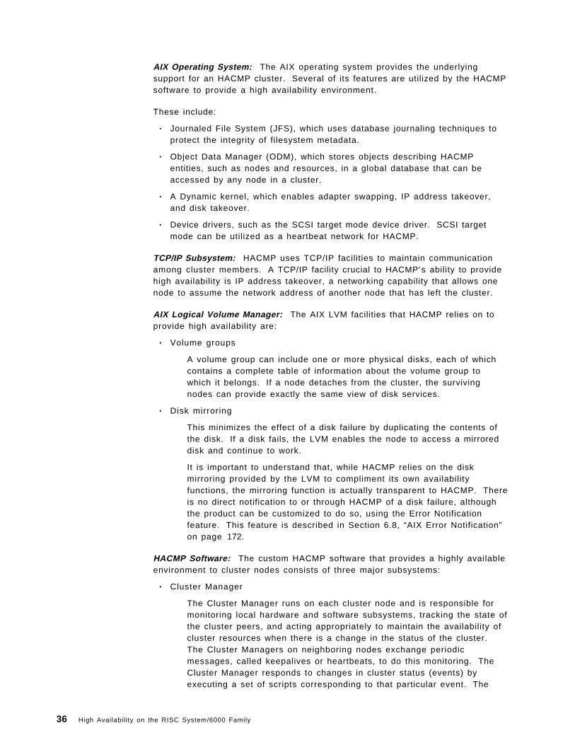
AIX Operating System: The AIX operating system provides the underlyingsupport for an HACMP cluster. Several of its features are utilized by the HACMPsoftware to provide a high availability environment.
These include:
• Journaled File System (JFS), which uses database journaling techniques toprotect the integrity of filesystem metadata.
• Object Data Manager (ODM), which stores objects describing HACMPentities, such as nodes and resources, in a global database that can beaccessed by any node in a cluster.
• A Dynamic kernel, which enables adapter swapping, IP address takeover,and disk takeover.
• Device drivers, such as the SCSI target mode device driver. SCSI targetmode can be utilized as a heartbeat network for HACMP.
TCP/IP Subsystem: HACMP uses TCP/IP facilities to maintain communicationamong cluster members. A TCP/IP facility crucial to HACMP′s ability to providehigh availability is IP address takeover, a networking capability that allows onenode to assume the network address of another node that has left the cluster.
AIX Logical Volume Manager: The AIX LVM facilities that HACMP relies on toprovide high availability are:
• Volume groups
A volume group can include one or more physical disks, each of whichcontains a complete table of information about the volume group towhich it belongs. If a node detaches from the cluster, the survivingnodes can provide exactly the same view of disk services.
• Disk mirroring
This minimizes the effect of a disk failure by duplicating the contents ofthe disk. If a disk fails, the LVM enables the node to access a mirroreddisk and continue to work.
It is important to understand that, while HACMP relies on the diskmirroring provided by the LVM to compliment its own availabilityfunctions, the mirroring function is actually transparent to HACMP. Thereis no direct notification to or through HACMP of a disk failure, althoughthe product can be customized to do so, using the Error Notificationfeature. This feature is described in Section 6.8, “AIX Error Notification”on page 172.
HACMP Software: The custom HACMP software that provides a highly availableenvironment to cluster nodes consists of three major subsystems:
• Cluster Manager
The Cluster Manager runs on each cluster node and is responsible formonitoring local hardware and software subsystems, tracking the state ofthe cluster peers, and acting appropriately to maintain the availability ofcluster resources when there is a change in the status of the cluster.The Cluster Managers on neighboring nodes exchange periodicmessages, called keepalives or heartbeats, to do this monitoring. TheCluster Manager responds to changes in cluster status (events) byexecuting a set of scripts corresponding to that particular event. The
36 High Availability on the RISC System/6000 Family

cluster manager can be started explicitly through SMIT, or automaticallyupon startup of the system.
• Cluster SMUX Peer and Cluster Information Services
An HACMP cluster is dynamic and can undergo various changes in itsstate over time. An example of this would be a node joining or leavingthe cluster, or a standby adapter taking over from a service adapter. Ifthe clients are not aware of the changes to the cluster, all the changesmay not be completely transparent to the end user. If the clients areaware of the changes in the state of the cluster, they can react to thesechanges and possibly mask them from the end user.
The HACMP software provides notification of cluster state changes toclients through the Cluster SMUX Peer and Cluster Information Services.
The Cluster SMUX Peer Service provides Simple Network ManagementProtocol (SNMP) support to client applications. For information onSNMP, please refer to the publication AIX Version 3.2 for the IBM RISCSystem/6000 Communications Concepts and Procedures. The ClusterSMUX Peer daemon, clsmuxpd, maintains cluster status information in aspecial HACMP/6000 Management Information Base (MIB).
Cluster Information daemon, clinfo, is an SNMP network monitor whichcan be started with the Cluster Manager from SMIT or at system startup.It runs on cluster nodes or client machines and queries the clsmuxpddaemon at regular intervals for updated cluster information. Applicationsrunning on these client machines can use the clinfo ApplicationProgramming Interfaces (APIs) documented with HACMP to track thestatus of the cluster. The Programming Client Applications manualdescribes how you can use these APIs.
• Cluster Lock Manager
The Concurrent Resource Manager subsystem of HACMP implementsadvisory locking, to ensure the integrity of data that is being concurrentlyaccessed by applications running on multiple nodes in a cluster. Thismeans that all applications accessing data concurrently should firstobtain a lock from the lock manager before manipulating the data.Applications can do this by using the APIs provided by the Cluster LockManager. The Programming Locking Applications manual describes howyou can use these APIs. The Cluster Lock Manager runs as the cllockddaemon which can be started with the Cluster Manager from SMIT or atsystem startup.
A detailed description of how the HACMP daemons function is given inAppendix A, “HACMP Software Components” on page 199.
3.2.2.3 Eliminating Single Points of Failure Using HACMPThe HACMP software allows a cluster to continue to provide application serviceseven though a key system component is no longer available. When acomponent becomes unavailable, HACMP detects the loss and shifts thatcomponent ′s workload to another component in the cluster. The failure recoveryis done automatically by the event scripts, provided with HACMP, without anyhuman intervention. The purpose of the product design is to avoid anycomponent being a single point of failure.
The cluster components that are potential single points of failure include:
Chapter 3. Clustering RISC System/6000s for High Availability 37
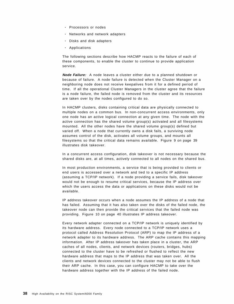
• Processors or nodes
• Networks and network adapters
• Disks and disk adapters
• Applications
The following sections describe how HACMP reacts to the failure of each ofthese components, to enable the cluster to continue to provide applicationservice.
Node Failure: A node leaves a cluster either due to a planned shutdown orbecause of failure. A node failure is detected when the Cluster Manager on aneighboring node does not receive keepalives from it for a defined period oftime. If all the operational Cluster Managers in the cluster agree that the failureis a node failure, the failed node is removed from the cluster and its resourcesare taken over by the nodes configured to do so.
In HACMP clusters, disks containing critical data are physically connected tomultiple nodes on a common bus. In non-concurrent access environments, onlyone node has an active logical connection at any given time. The node with theactive connection has the shared volume group(s) activated and all filesystemsmounted. All the other nodes have the shared volume group(s) defined butvaried off. When a node that currently owns a disk fails, a surviving nodeassumes control of the disk, activates all volume groups, and mounts allfilesystems so that the critical data remains available. Figure 9 on page 39illustrates disk takeover.
In a concurrent access configuration, disk takeover is not necessary because theshared disks are, at all times, actively connected to all nodes on the shared bus.
In most production environments, a service that is being provided to clients orend users is accessed over a network and tied to a specific IP address(assuming a TCP/IP network). If a node providing a service fails, disk takeoverwould not be enough to resume critical services, because the IP address overwhich the users access the data or applications on these disks would not beavailable.
IP address takeover occurs when a node assumes the IP address of a node thathas failed. Assuming that it has also taken over the disks of the failed node, thetakeover node can then provide the critical services that the failed node wasproviding. Figure 10 on page 40 illustrates IP address takeover.
Every network adapter connected on a TCP/IP network is uniquely identified byits hardware address. Every node connected to a TCP/IP network uses aprotocol called Address Resolution Protocol (ARP) to map the IP address of anetwork adapter to its hardware address. The ARP cache contains this mappinginformation. After IP address takeover has taken place in a cluster, the ARPcaches of all nodes, clients, and network devices (routers, bridges, hubs)connected to the cluster have to be refreshed or flushed to reflect the newhardware address that maps to the IP address that was taken over. All theclients and network devices connected to the cluster may not be able to flushtheir ARP cache. In this case, you can configure HACMP to take over thehardware address together with the IP address of the failed node.
38 High Availability on the RISC System/6000 Family

Figure 9. Disk Takeover
If a critical application or process was running on a node that fails, a takeovernode can restart that application or process so that the service is not lost.
Network and Network Adapter Failure: A network is determined to have failedwhen no node in the cluster is able to communicate across it. It isrecommended that you design your cluster with more than one network,whatever the attribute (public, private, or serial), so that HACMP has at least onenetwork at all times that it can use to monitor the status of cluster nodes. Ifthere is more than one network to which all cluster nodes are connected, theCluster Manager detects a network failure, but takes no action. If the failingnetwork is a public network over which critical services are accessed, it isimperative that connectivity is restored. One of the possible ways you can
Chapter 3. Clustering RISC System/6000s for High Availability 39

Figure 10. IP Address Takeover
eliminate this single point of failure is by having the nodes in the clusterconnected over multiple public networks and by customizing the scripts thathandle network failures to reroute all traffic through an alternate network.
When the service adapter on a node fails, the Cluster Manager swaps the rolesof the service and standby adapters on that node. The end user just sees hisscreen freeze for a few seconds (the exact time depends on the type of network)before he can continue. The failure of a standby adapter is detected and loggedby the Cluster Manager, but no default action is taken. If you wish the ClusterManager to take further action when a standby adapter fails, you can customizethe reaction to this event. Figure 11 on page 41 illustrates adapter swapping
40 High Availability on the RISC System/6000 Family

Figure 11. Adapter Swapping
Disk and Disk Adapter Failure: HACMP does not directly handle disk and diskadapter failures.
If you are using SCSI disk drives or 9333 serial disk subsystems, you canconfigure your cluster nodes with multiple SCSI or serial chains and have yourdisks mirrored across these chains. If you are using SSA disks, you canconfigure your cluster with multiple loops, and mirror your disks across loops.In this way, your critical data is protected against the failure of any singlecomponent of storage hardware (adapter, cabling, disks).
If you are using the 7135-110 RAIDiant Disk Array or the 7137/3514 Disk Array,data protection is already built in. You need to design the connection to thesearrays to protect against failures of cables and adapters.
Please refer to Appendix B, “Disk Setup in an HACMP Cluster” on page 209 forfurther details of cabling different storage products in a no single point of failureconfiguration.
Application Failure: HACMP cannot detect the failure of an application by itself.If a node goes down, any application that was running on it can be configured tobe restarted on a takeover node. The Cluster Manager can be configured tostart any critical application when a node joins a cluster for the first time or aftera failure.
Further, the AIX System Resource Controller (SRC) can be used to monitor forthe presence or absence of an application ′s daemon and respond accordingly.
Chapter 3. Clustering RISC System/6000s for High Availability 41

In conclusion, HACMP can detect most types of failure and recover from them inorder to keep critical services available to the end user. The time taken torecover varies from thirty to three hundred seconds or more, depending on theamount of disk storage to be taken over in the case of a node failure and theamount of customization that you add to the recovery scripts.
3.2.3 HACMP Cluster ResourcesHACMP provides a highly available environment by identifying a set ofcluster-wide resources essential to uninterrupted processing and then definingrelationships among nodes that ensure these resources are available to clientprocesses.
When a cluster node fails or detaches from the cluster for a scheduled outage,the Cluster Manager redistributes its resources among any number of thesurviving nodes.
These resources can include the following:
• Disks
• Volume Groups
• Filesystems
• Filesystems to be NFS mounted
• Filesystems to be NFS exported
• Service IP addresses
• Applications
3.2.3.1 Resource GroupsEach resource in a cluster is defined as part of a resource group. This allowsyou to combine related resources that need to be together to provide aparticular service. A resource group also includes the list of nodes that canacquire those resources and serve them to clients.
A resource group is defined as one of three types:
• Cascading
• Rotating
• Concurrent
Each of these types describes a different set of relationships between nodes inthe cluster, and a different set of behaviors upon nodes entering and leaving thecluster.
Cascading Resource Groups: All nodes in a cascading resource group areassigned priorities for that resource group. These nodes are said to be part ofthat group′s resource chain. In a cascading resource group, the set of resourcescascades up or down to the highest priority node active in the cluster. When anode who is serving the resources fails, the surviving node with the highestpriority takes over the resources. A picture of a cascading resource group is inFigure 12 on page 43.
42 High Availability on the RISC System/6000 Family

Figure 12. Cascading Resource Group
A parameter called Inactive Takeover decides which node takes the cascadingresources when the nodes join the cluster for the first time. If this parameter isset to true, the first node in a group′s resource chain to join the cluster acquiresall the resources in the resource group. As successive nodes join, theresources cascade up to any node with a higher priority that joins the cluster. Ifthis parameter is set to false, the first node in a group′s resource chain to jointhe cluster acquires all the resources in the resource group only if it is the nodewith the highest priority for that group. If the first node to join does not acquirethe resource group, the second node in the group′s resource chain to join, if ithas a higher priority than the node already active, acquires the resource group.As successive nodes join, the resource group cascades to the active node withthe highest priority for the group. The default is false.
Member nodes of a cascading resource chain always release a resource groupto a reintegrating node with a higher priority.
Rotating Resource Groups: A rotating resource group is associated with agroup of nodes, rather than a particular node. A node can be in possession of amaximum of one rotating resource group per network.
Chapter 3. Clustering RISC System/6000s for High Availability 43

As participating nodes join the cluster for the first time, they acquire the firstavailable rotating resource group per network until all the groups are acquired.The remaining nodes remain on standby.
When a node holding a rotating resource group leaves the cluster, eitherbecause of a failure or gracefully while specifying the takeover option, the nodewith the highest priority and available connectivity takes over. On reintegration,a node remains as a standby and does not take back any of the resources that ithad initially served. A picture of a rotating resource group is in Figure 13.
Figure 13. Rotating Resource Group
Concurrent Resource Groups: A concurrent resource group may be sharedsimultaneously by multiple nodes. The resources that can be part of aconcurrent resource group are limited to volume groups with raw logicalvolumes, and raw disks.
When a node fails, there is no takeover involved for concurrent resources. Onreintegration, a node once again accesses the resources simultaneously with theother nodes. A picture of a concurrent resource group is in Figure 14 onpage 45.
44 High Availability on the RISC System/6000 Family

Figure 14. Concurrent Resource Group
The Cluster Manager makes the following assumptions about the acquisition ofresource groups:
Cascading The active node with the highest priority controls theresource group.
Concurrent All active nodes have access to the resource group.
Rotating The node with the rotating resource group′s associatedservice IP address controls the resource group.
3.2.4 HACMP Cluster ConfigurationsThere are several ways in which you can configure your cluster to provide highavailability. In this section, we will discuss a few basic failover configurationsthat you can use to design the cluster best suited to your availabilityrequirements.
In most of the examples that follow, we will be using two node or three nodeclusters, but the same principles can be extended to larger clusters. When youdesign larger clusters, you should keep SCSI bus limitations and concurrentaccess limitations in mind. Please refer to Appendix B, “Disk Setup in anHACMP Cluster” on page 209 for further details of limitations related to storage.
The HACMP software has no knowledge of these failover strategies. Theconfigurations are implemented using resource groups and their relationshipswith the cluster nodes. All the examples of resource groups in this section haveonly disks as constituent resources. This has been done for convenience only.The same concepts are easily extended to other resources such as IP addressesand applications.
The first distinction that you need to make while designing a cluster is whetheryou need a non-concurrent or a concurrent disk access environment.
Chapter 3. Clustering RISC System/6000s for High Availability 45

3.2.4.1 Non-Concurrent Disk Access ConfigurationsThe possible non-concurrent disk access configurations are:
• Hot Standby
• Rotating Standby
• Mutual Takeover
• Third-Party Takeover
Hot Standby Configuration: Figure 15 illustrates a two node cluster in a hotstandby configuration.
Figure 15. Hot Standby Configuration
In this configuration, there is one cascading resource group consisting of thefour disks, hdisk1 to hdisk4, and their constituent volume groups and filesystems.Node 1 has a priority of 1 for this resource group while node 2 has a priority of 2.During normal operations, node 1 provides all critical services to end users.Node 2 may be idle or may be providing non-critical services, and hence isreferred to as a hot standby node. When node 1 fails or has to leave the clusterfor a scheduled outage, node 2 acquires the resource group and starts providingthe critical services.
The advantage of this type of a configuration is that you can shift from a singlesystem environment to an HACMP cluster at a low cost by adding a lesspowerful processor. Of course, this assumes that you are willing to accept alower level of performance in a failover situation. This is a trade-off that you willhave to make between availability, performance, and cost.
Rotating Standby Configuration: This configuration is the same as the previousconfiguration except that the resource groups used are rotating resource groups.
In the hot standby configuration, when node 1 reintegrates into the cluster, ittakes back the resource group since it has the highest priority for it. Thisimplies a break in service to the end users during reintegration.
46 High Availability on the RISC System/6000 Family

If the cluster is using rotating resource groups, reintegrating nodes do notreacquire any of the resource groups. A failed node that recovers and rejoinsthe cluster becomes a standby node. You would choose a rotating standbyconfiguration if you do not want a break in service during reintegration.
Since takeover nodes continue providing services till they have to leave thecluster, you should configure your cluster with nodes of equal power. While at ahigher price in CPU hardware, a rotating standby configuration gives you betteravailability and performance than a hot standby configuration.
Mutual Takeover Configuration: Figure 16 illustrates a two node cluster in amutual takeover configuration.
Figure 16. Mutual Takeover Configuration
In this configuration, there are two cascading resource groups A and B.Resource group A consists of two disks, hdisk1 and hdisk3, and one volumegroup, sharedvg. Resource group B consists of two disks, hdisk2 and hdisk4,and one volume group, databasevg. Node 1 has priorities of 1 and 2 forresource groups A and B respectively, while Node 2 has priorities of 1 and 2 forresource groups B and A respectively.
During normal operations, nodes 1 and 2 have control of resource groups A andB respectively, and both provide critical services to end users. If either node 1or node 2 fails or has to leave the cluster for a scheduled outage, the survivingnode acquires the failed node′s resource groups and continues to provide thefailed node′s critical services.
When a failed node reintegrates into the cluster, it takes back the resourcegroup for which it has the highest priority. Therefore, even in this configuration,there is a break in service during reintegration. Of course, if you look at it fromthe point of view of performance, this is the best thing to do, since you have onenode doing the work of two only when any one of the nodes is down.
Third-Party Takeover Configuration: Figure 17 on page 48 illustrates a three
Chapter 3. Clustering RISC System/6000s for High Availability 47

Figure 17. Third-Party Takeover Configuration
node cluster in a third-party takeover configuration. This configuration takescare of the performance degradation that results from a failover in the mutualtakeover configuration.
Here the resource groups are the same as the ones in the mutual takeoverconfiguration. Also, similar to the previous configuration, nodes 1 and 2 eachhave priorities of 1 for one of the resource groups, A or B. The only thingdifferent in this configuration is that there is a third node which has a priority of 2for both the resource groups.
During normal operations, node 3 is either idle or is providing non-criticalservices. In the case of either node 1 or node 2 failing, node 3 takes over thefailed node′s resource groups and starts providing its services. When a failednode rejoins the cluster, it reacquires the resource group for which it has thehighest priority.
So, in this configuration, you are protected against the failure of two nodes andthere is no performance degradation after the failure of one node.
48 High Availability on the RISC System/6000 Family

3.2.4.2 Concurrent Disk Access ConfigurationsA concurrent disk access configuration usually has all its disk storage defined aspart of one concurrent resource group. The nodes associated with a concurrentresource group have no priorities assigned to them.
If 7135 RAIDiant Array Subsystems or 7137/3514 Disk Array Subsystems are usedfor storage, you can have a maximum of four nodes concurrently accessing a setof storage resources. If you are using the 9333-501 High-Performance Disk DriveSubsystem, you can have up to eight nodes concurrently accessing it.
In the case of a node failing, a concurrent resource group is not explicitly takenover by any other node, since it is already active on the other nodes. However,in order to somewhat mask a node failure from the end users, you should alsohave cascading resource groups, each containing the service IP address foreach node in the cluster. When a node fails, its service IP address will get takenover by another node and users can continue to access critical services at thesame IP address that they were using before the node failed.
3.2.5 HACMP Cluster EventsCluster events correspond to changes in the status of nodes, networks, andnetwork adapters, and to reaching time limits during the reconfiguration process.
Each cluster event has an associated shell script which is executed by theCluster Manager in response to that event. Each event script may start a seriesof subevent scripts, depending on the cluster configuration and the state of thecluster.
The Cluster Manager in an HACMP cluster detects and reacts to the followingevents:
• A node trying to join the cluster.
• A node leaving the cluster.
• A network going down.
• A network coming up.
• IP address being swapped between a service and a standby adapter.
• The cluster being unstable or in reconfiguration for too long.
3.2.5.1 Node EventsA node event could be a node joining the cluster or a node leaving the cluster.A node joins the cluster when the Cluster Manager is started on that node, andleaves the cluster when the Cluster Manager is stopped. A node can leave thecluster due to a failure or a planned outage. If a node has to be brought downfor any kind of maintenance, the Cluster Manager can be shut down in one ofthree ways:
• Graceful Shutdown
The node gives up all the resources that it had acquired when it joinedthe cluster. These resources do not get taken over by any of the othernodes in the cluster even if they were configured to do so.
• Graceful Shutdown With Takeover
The node gives up all the resources that it had acquired when it joinedthe cluster. Depending on the nature of the resource groups defined for
Chapter 3. Clustering RISC System/6000s for High Availability 49

the cluster and their relationships with the cluster nodes, the resourcesare taken over by other active nodes in the cluster.
• Forced Shutdown
The node does not give up any of its resources and consequently theseresources do not get taken over by any of the other nodes in the cluster.A forced shutdown just stops the Cluster Manager and any other HACMPdaemon that was running on the node.
The flowchart in Figure 18 on page 51 shows the series of event scripts that areexecuted when the first node joins the cluster. The flowchart in Figure 19 onpage 52 shows the sequence of execution of event scripts when a node joins acluster that already has one or more active nodes.
The sequence in which event scripts get executed on active nodes after a clusternode fails is shown in Figure 20 on page 53. When a node leaves a cluster for ascheduled outage, event scripts are executed only if the HACMP services areshut down gracefully with takeover. The event scripts that get executed on thenode that is leaving and the active nodes is shown in Figure 21 on page 54.
In the figures, please note the only node event scripts that get executed directlyby the Cluster Manager are:
node_upnode_up_completenode_downnode_down_complete
These scripts in turn execute the other scripts.
3.2.5.2 Network EventsA network event could be a network becoming available for use by cluster nodesor a network failing. When the Cluster Manager determines that a network hasfailed, a network_down event occurs. When a network becomes available foruse in a cluster, the network_up event occurs.
A network failure can be further classified into two cases:
• Local
When only one node has lost contact with a network, the failure is said tobe local.
• Global
When all the nodes in the cluster have lost contact with a network, thefailure is said to be global.
The network_down event sends mail to the system administrator, informing himof the failure, but does not do anything else. The network_up event script takesno default action.
The network_down_complete and the network_up_complete scripts get executedonly after a network_down or a network_up event gets completed successfully.
These scripts do not do anything by default, since the appropriate action woulddepend on the local network configuration. You can customize themaccordingly.
50 High Availability on the RISC System/6000 Family

Figure 18. First Node Joins Cluster
Network Adapter Events: The network adapter events that the Cluster Managerreacts to are:
swap_adapter
This occurs when the service adapter on a node fails and there is astandby adapter available on that node on the same network. The scriptfor this event, by default, exchanges the IP addresses of the service andthe standby adapter, and reconstructs the routing table.
swap_adapter_complete
This event occurs only after the swap_adapter event has successfullycompleted. The script ensures that the local ARP cache is updated bydeleting entries and pinging cluster IP addresses.
fail_standby
This event occurs when the standby adapter is no longer available,either because it has taken over a service IP address or because of itsown failure. The script for this event sends a message to the consoleindicating the loss of the standby adapter.
Chapter 3. Clustering RISC System/6000s for High Availability 51
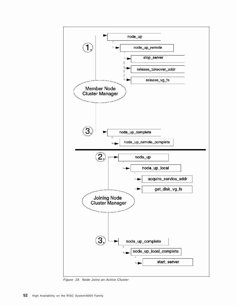
Figure 19. Node Joins an Active Cluster
52 High Availability on the RISC System/6000 Family

Figure 20. Node Fails
join_standby
This happens when a standby adapter becomes available for use again.The event script sends a message to the console indicating theavailability of the standby adapter.
3.2.5.3 Cluster Status EventsIf the cluster remains in reconfiguration for more than six minutes after a changein status due to a failure or reintegration, the config_too_long event is triggered,and the Cluster Manager starts displaying a message periodically on theconsole.
If a cluster node has been processing topology changes for more than sixminutes, the unstable_too_long event is initiated, and the Cluster Manager startsdisplaying a message periodically on the console.
3.2.5.4 Cluster Event LogsThere are three log files that HACMP uses in order to keep a record of allchanges in a cluster′s state. You can use these files in order to find out thehistory of a cluster or to trouble-shoot a cluster that has been misbehaving.
The log files that HACMP writes to are:
1. /usr/adm/cluster.log
This file contains time-stamped messages indicating the occurrence ofevent scripts and messages from the HACMP daemons.
Chapter 3. Clustering RISC System/6000s for High Availability 53
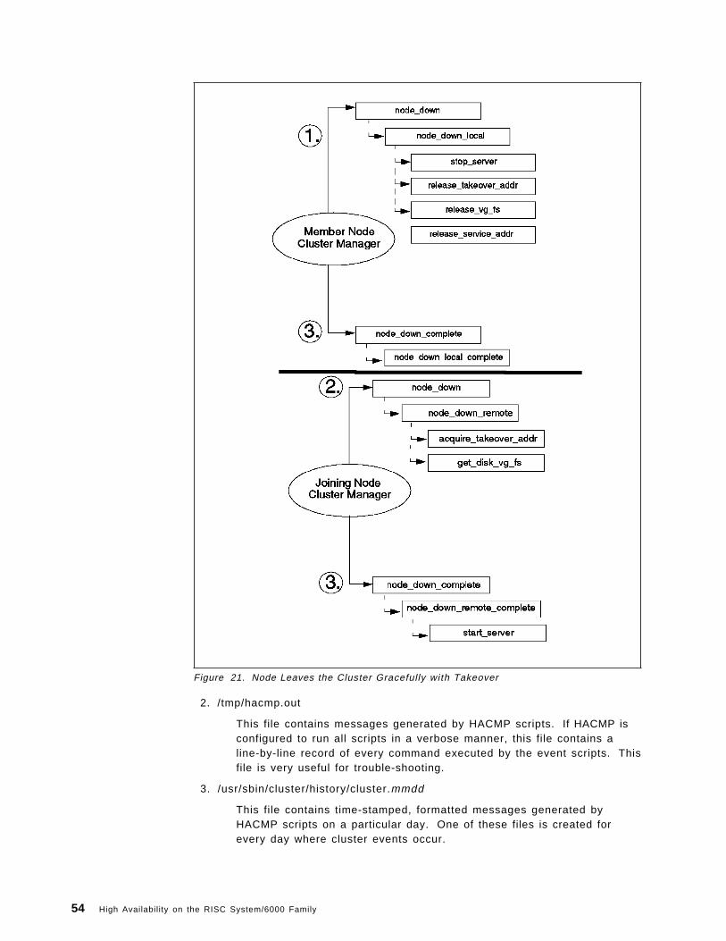
Figure 21. Node Leaves the Cluster Gracefully with Takeover
2. /tmp/hacmp.out
This file contains messages generated by HACMP scripts. If HACMP isconfigured to run all scripts in a verbose manner, this file contains aline-by-line record of every command executed by the event scripts. Thisfile is very useful for trouble-shooting.
3. /usr/sbin/cluster/history/cluster.mmdd
This file contains time-stamped, formatted messages generated byHACMP scripts on a particular day. One of these files is created forevery day where cluster events occur.
54 High Availability on the RISC System/6000 Family

3.2.5.5 Customizing Cluster BehaviorThe Cluster Manager has a default behavior, coded into the event scripts, inresponse to each event. You can add further functionality to the eventprocessing by using the event customization facility that HACMP provides.
This facility includes:
• Pre and post-event processing
Using this facility, you can specify scripts to be run before and after theexecution of the default script for any event.
It is preferable to use the pre and post-event scripts to do anycustomization rather than to change any of the default scripts that comewith the HACMP product, since the default scripts may be changed byPTFs delivered by IBM over time.
• Event notification
You can use this facility to notify users or system administrators aboutthe occurrence of a particular event.
• Event recovery and retry
This facility allows you to specify a script that attempts to recover fromthe failure of an event script (indicated by a non-zero return code). If therecovery command executes without errors, and the retry count that youhave specified for the event is greater than zero, the Cluster Managerreruns the event script.
Figure 22 on page 56 shows the sequence in which these scripts are executedand the conditions that apply to the flow of execution. We will deal withcustomization in greater detail in Chapter 6, “Cluster Tuning and Customization”on page 159.
3.2.6 Clients in an HACMP ClusterThe HACMP Licensed Program Product comes packaged with a servercomponent and a client component. Both these components need to be installedon the cluster nodes. You can also install the client portion of the HACMPsoftware on any RS/6000 that you want to use as a client to your cluster.
The client portion of HACMP, when installed on an RS/6000 client, starts theclinfo daemon at system startup. It comes with a set of ApplicationProgramming Interfaces (APIs) that can be used by client applications to monitorthe status of an HACMP cluster and to mask any failures of cluster componentsfrom the end user. The APIs are described fully in the HACMP/6000 Version 3.1Programming Client Applications manual. The client portion of HACMP alsoprovides a utility called clstat, which you can use to monitor the status of yourcluster nodes, networks, and network adapters. This monitor can be viewedeither in graphics form or ascii form, depending on the terminal type it is startedfrom. The source code for the client portion of HACMP is also provided with theproduct, to allow it to be ported to non-RS/6000 clients.
You should have all your users who are accessing cluster services connectedover a TCP/IP network and not from serial ports directly attached to one of thecluster nodes. This is because HACMP does not detect or recover from thefailure of serial ports and asynchronous adapters. Also, physical replugging ofterminals from one machine to another would be required in the case of a node
Chapter 3. Clustering RISC System/6000s for High Availability 55

Figure 22. Flow of Execution of Event Scripts
failure. This would, of course, cause much more impact to users in a failuresituation.
You can have your users working on terminals connected to a terminal serverwhich is on the public network. In this case, a network adapter failure would betransparent to the users, but a node failure would cause some impact. If thenode to which users are logged in were to fail, the telnet sessions of the userswould get killed. The users would then have to wait until IP address takeoverhad completed before they could log on again.
Different terminal servers have different capabilities. For instance, a terminalserver may not be able to flush its ARP cache after an IP address takeover. Ifthis is the case with your terminal server, you can configure your servicenetwork adapters for hardware address takeover in HACMP. If this is done, thehardware address of the service adapter is moved along with the IP address,and there is no need to flush ARP caches on client devices.
To provide the best failure transparency to your users, you should use clientmachines, connected to a public network and running a client application. Theclient application would access a server application on a cluster node at aparticular service IP address.
In this scenario, an attempt to initiate a connection during failover, depending onthe connection protocol being used (TCP or UDP), would either time out or retryuntil IP address takeover was completed. If your client application used UDP to
56 High Availability on the RISC System/6000 Family

connect to the server node, network adapter and node failures would both bequite transparent to users, resulting in only a delay in response, and not a lossof connection.
If your cluster is configured for concurrent access, you need not wait for IPaddress takeover. Your client application can use the clinfo APIs to detect nodefailure and connect to another node where the same disks and applications areavailable. This would avoid the delay of sending the transaction to a failed nodefirst, and waiting for the reconnection time.
The end users could also be shielded from the failure of a public network, if youcustomize the cluster to react to a network failure by routing traffic through analternate network.
3.3 ConclusionIn this chapter, we have seen how we can provide a highly availableenvironment for critical services by using a cluster of RS/6000s, with or withoutthe HACMP software. We have also seen the advantages of using the HACMPproduct, namely the flexibility in cluster design, responsiveness, and ease ofcustomization.
In the next chapter, we will describe the actual steps involved in setting up anHACMP cluster.
Chapter 3. Clustering RISC System/6000s for High Availability 57

58 High Availability on the RISC System/6000 Family

Chapter 4. Hardware Options for HACMP
One of HACMP′s key design strengths is its ability to provide support across theentire range of RISC System/6000 products. Because of this built-in flexibilityand the facility to mix and match RISC System/6000 products, the effort requiredto design a highly available cluster is significantly eased.
In this chapter, we shall outline the various hardware options supported byHACMP/6000 Version 3.1 and where appropriate, make reference to HACMP 4.1for AIX. We realize that the rapid pace of change in products will almostcertainly render any snapshot of the options to be out of date by the time it ispublished. This is true of almost all technical writing, though to yield to thespoils of obsolescence probably means nothing would ever make it to theprinting press.
The following sections will deal with the various:
• CPU Options
• Storage Options
• Connectivity Options
available to you when you are planning your HACMP cluster.
4.1 CPU OptionsHACMP is designed to execute with RISC System/6000 uniprocessors andSymmetric Multi-Processor (SMP) servers in a no single point of failure serverconfiguration. The minimum configuration and sizing of each system CPU ishighly dependent on the user′s application and data requirements.Nevertheless, systems with 32MB of main storage and 1GB of disk storage wouldbe practical, minimum configurations.
Almost any model of the RISC System/6000 POWERserver family can be includedin an HACMP environment and new models continue to added to the list. Thefollowing RISC System/6000 model form-factors are currently supported as nodesin an HACMP/6000 Version 3.1 cluster:
• 7009 Compact Server C10
• 7011-2XX Entry-Level Desktop Servers
• 7012-3XX Desktop Servers
• 7013-5XX Deskside Servers
• 7015-9XX Rack-Mounted Servers
For a detailed description of system models supported by HACMP, you shouldrefer to the current Announcement Letters for HACMP/6000 Version 3.1 andHACMP 4.1 for AIX.
HACMP 4.1 for AIX enhances cluster design flexibility even further by includingsupport for the Symmetric Multi-Processor (SMP) family of machines and theCompact Server C20. With the introduction of support for SMP family ofprocessors you are now able to mix and match processors; a cluster can consistof a combination of uniprocessor and SMP nodes. It should be noted, however,
Copyright IBM Corp. 1995 59

that at the time this chapter was written, HACMP 4.1 for AIX offered concurrentaccess support for RAID array subsystems only. Concurrent accessconfigurations using serial disk subsystems were not yet supported. Pleasecheck with your IBM support person to see what functions are available as youread this document.
4.2 How to Select CPU Nodes for Your ClusterIt is important to understand that selecting the system components for a clusterrequires careful consideration of factors and information that may not beconsidered in the selection of equipment for a single system environment. Inthis section, we will offer some guidelines to assist you with choosing and sizingappropriate machine models to build your clusters.
Much of the decision centers around the following areas:
• Processor capacity
• Application requirements
• Anticipated growth requirements
• I/O slot requirements
These paradigms are certainly not new ones, and are also importantconsiderations when choosing a processor for a single system environment.However, when designing a cluster, you must carefully consider requirements ofthe cluster as total entity. This includes understanding system capacityrequirements of other nodes in the cluster beyond the requirements of eachsystem ′s prescribed normal load. You must consider the required performanceof the solution during and after failover, when a surviving node has to add theworkload of a failed node to its own workload.
For example, in a two node cluster, where applications running on both nodesare critical to the business, each of the two nodes would function as a backup forthe other, in a mutual takeover configuration. If a node were required to providefailover support for all the applications on the other node, then its capacity wouldneed to be very much larger than would otherwise be required. Essentially, thechoice of a model will depend on the requirements of highly availableapplications, not only in terms of CPU cycles, but also of memory and possiblydisk. Approximately 15MB of disk storage is required for the HACMP software.
A major consideration in the selection of models will be the number of I/Oexpansion slots needed. The model selected must have enough slots to housethe components required to remove single points of failure (SPOFs) and providethe desired level of availability. As mentioned in Section 3.1.2, “Single Points ofFailure” on page 26, a single point of failure can be defined as any singlecomponent in a cluster whose failure would cause a service to becomeunavailable to end users. The more single points of failure you can eliminate,the higher your level of availability will be. Typically, you need to consider thenumber of slots required to support network adapters and disk I/O adapters.Your slot configuration must provide for at least two network adapters to provideadapter redundancy for one service network. If your system needs to be able totake over an IP address for more than one other system in the cluster at a time,you will want to configure more standby network adapters. You may have up toseven standby adapters in a node, slots permitting.
60 High Availability on the RISC System/6000 Family

Your slot configuration must also allow for the disk I/O adapters you need tosupport the cluster ′s shared disk (volume group) configuration. If you intend touse disk mirroring for shared volume groups, which is strongly recommended,then you will need to use slots for additional disk I/O adapters, providing I/Oadapter redundancy across separate buses. See Figure 44 on page 186 for asample method of eliminating disk I/O adapters as single points of failure.
Because of limited slot capacity, you will not be able to include enoughredundant hardware features in a model 2XX to provide a cluster with no singlepoint of failure. For small cluster nodes, that is, nodes requiring no more thanone network and two disk I/O adapters for a mirrored shared volume group, 3XXmodels may be suitable. The limitation is that virtually all the available slots areconsumed by adapters at the time of installation just to eliminate single points offailure. This leaves very limited potential for further growth in I/O, or capacity tosupport additional hardware function such as serial ports, graphics adapters orwide area networks. However, HACMP is configurable to allow you to select thelevel of availability that can be justified. A single point of failure may bejustifiable, based on a calculated risk, but this will obviously vary from site tosite. Therefore, 2XX and 3XX models are supported and can be used in clusterconfigurations.
4.2.1 Node Configuration GuidelinesThere are three well defined RISC System/6000 model categories: desktop,deskside, and rack-mounted. Each of these has appropriate application in anHACMP environment as well as limitations. The following clustering exampleshave been aligned to the RISC System/6000 model range and defined as small,medium, and large nodes.
We have mentioned the importance of sufficient I/O slots to support theelimination of single points of failure. It is easy to become caught up with thehigh availability design and to neglect the slot requirements for hardwaresupport outside the highly available environment. For each of the categoriesbelow, the slot count required for other hardware, such as graphics adapters,3270 connection adapters, multi-protocol adapters, async adapters, and hostinterface adapters, should also be considered.
Small Capacity Node: Desktop (3XX) and Compact Server (CXX) models are, inpractice, suitable only for clusters consisting of two or three nodes. Beyond thisnumber, the slot limitations of these models prevent the elimination of singlepoints of failure in network and disk I/O resources. Typically, this is a clusterthat may support one service network and up to two strings of shared disk. Diskmirroring is implemented across the two buses, to eliminate disk I/O adapters assingle points of failure. For a cluster configuration of this type, you will need twonetwork adapters (service and standby) and two disk I/O adapters in each node.If the network type is ethernet, you can use the integrated ethernet port foreither the service or standby interface on a 3XX system. Given that a desktopsystem has four slots, this configuration will leave only one slot for an additionaladapter. For example, this type of configuration may suit a highly availablegraphics workstation environment for newspaper publishing. For otherenvironments, if there were no foreseeable growth in application or dataprocessing requirements, this represents an effective and low cost solution.
The Compact Server systems have only four slots and no integrated ethernetadapter. Therefore, the Compact Server limits you even more because all slots
Chapter 4. Hardware Options for HACMP 61

will be used just to satisfy the requirements for high availability. Any servicesthat require an additional adapter will not be satisfied by a compact server.
Token-ring or FDDI network environments render the suitability of desktopsystems equivalent to that of the compact servers. Whereas ethernetenvironments can make use of the integrated ethernet port, no such feature isavailable for token-ring or FDDI; you must use an I/O slot to provide token-ringadapter redundancy.
Medium Capacity Node: A medium capacity node is typically a node thatsupports tens to hundreds of gigabytes of shared disk storage and up to twonetworks (or three network interfaces).
The deskside uniprocessor servers (5XX) and, in particular, the SMP servers(JXX) are well suited to clusters of up to eight nodes. Currently, HACMPsupports no more than eight nodes in a cluster. The uniprocessor servers haveseven unused slots in their base configuration. The SMP servers have sixunused slots. Coupled to the J02 bus expansion unit, this number increases tofourteen. If you consider the small node capacity requirement of four slots toprovide no single point of failure, then the deskside servers will be a far betterchoice, providing the slot capacity for larger shared disk storage requirements,additional network adapters and other services.
With the ever increasing capacities of RAID subsystems and Serial StorageArchitecture (SSA) subsystems, slot capacity is becoming a less significant issuefor disk storage. However, if your network performance or availabilityrequirements dictate multiple physical LANs, then multiple adapters and slots,are required. If you require network redundancy and network adapterredundancy, then slots must be available to support the additional hardware.
Large Capacity Node: A large capacity node is typically a node that supports alarge amount of shared disk storage and multiple networks or networkinterfaces. A large amount of shared disk storage could translate to hundreds tothousands of gigabytes. Also, a large capacity node may be required to supportsix or more network adapters. To achieve this requires a large number of I/Oslots. Because the rack-mounted systems have twin micro channel buses thatprovide fifteen available I/O slots, they are well suited to large capacity clusteredenvironments of up to eight nodes. It should also be noted that the 7013-J30SMP could also participate in this category owing to its I/O slot expansioncapability.
Racks also offer a distinct packaging advantage with the ability to install twoCPUs in the same rack and install disk drawers such as the 7135 RAIDiant Array,7134 High-Density Disk Subsystem and the 9333 Serial Disk Subsystem.Separate power supplies can operate the CPU and disk drawers, so that, ifpower to one CPU fails, the other is not affected, and takeover of any resourcescan be performed if necessary. The system rack can also accommodate anuninterruptible power supply, which is a better alternative to battery backup.
For very large clusters with substantial shared disk, CPUs can be housed indedicated racks and cabled to multiples of racks containing RAID, serial or SCSIdisk subsystem drawers.
62 High Availability on the RISC System/6000 Family

4.3 Storage OptionsOne of the major elements in planning a highly available AIX configuration is theshared disk storage devices. The RISC System/6000 family has acomprehensive range of disk storage choices available to HACMP. Thesechoices can be divided into three main categories:
• Conventional SCSI disks, including SCSI-2 Differential and SCSI-2 DifferentialFast/Wide.
• RAID arrays (SCSI attached).
• Serial disks, including IBM 9333 and Serial Storage Architecture.
Note: The new Serial Storage Architecture (SSA) was only supported by HACMP3.1.1. at the time of publishing, but support for HACMP 4.1 for AIX and futurereleases is expected to be added over time. The HACMP 3.1.1 support isdelivered in PTF U438726, and is also included in all follow-on cumulative PTFs.
The decision to use a particular storage subsystem will rely on a number offactors such as inherent availability, function, performance, and cost.
The purpose of this section is to describe the various disk storage technologiesand how they fit into a highly available environment. We shall examine thefeatures of conventional SCSI storage technologies, RAID arrays, and serialdisks, and offer advice on how to choose the most appropriate type.
4.3.1 SCSI TechnologiesSCSI stands for Small Computer System Interface. It is a fully documented ANSIstandard (X3.131-1986). The SCSI standard has undergone a number ofenhancements, with the SCSI-2 Differential Fast/Wide standard being the mostcurrent. Over the past few years, IBM has announced improved SCSIimplementations in line with advancements in the SCSI standard:
• 1992 - SCSI-2 (ANSI X3T9.2 186-109)
• 1993 - SCSI-2 Differential (ANSI X3T9.2 186-109)
• 1994 - SCSI-2 Fast/Wide (ANSI X3T9.2/86-109 rev 10h)
• 1994 - SCSI-2 Differential Fast/Wide (ANSI X3T9.2/86-109 rev 10h)
In 1995, IBM announced an enhanced version of the SCSI-2 Differential Fast/Wideimplementation.
Note: SCSI Differential is also sometimes called SCSI Differential-Ended. Theterms are used interchangeably in this book.
SCSI is a bus-architected interface through which computers may communicatewith attached intelligent devices such as fixed disks, tape drives and CD-ROMs.
All the devices attached to the SCSI bus share it by competing for control. Thisis known as arbitration. If a SCSI device wins control of the bus and is aninitiator (usually an adapter), it can send commands to another device known asa target (usually a disk or tape drive). Only when that device is finished will thebus be made available to others.
A maximum of seven devices can be directly attached to SCSI, SCSI-2, andSCSI-2 Differential-Ended adapters. With enhancements to the standard, anddual-porting of adapters like the IBM SCSI-2 Fast/Wide and SCSI-2 Differential
Chapter 4. Hardware Options for HACMP 63

Fast/Wide adapters, support for up to seven devices on each port (givingfourteen in total) is available. The IBM Enhanced SCSI-2 Differential Fast/Wideadapter extends device support further by permitting attachment of up to sixsingle ended devices to the internal port and up to fifteen differential devices onthe external port. Table 1 summarizes the characteristics of SCSI adapterscurrently supported by HACMP.
The signaling mechanism used is different between a SCSI Single-Ended bus anda SCSI Differential bus.
Table 1. SCSI Adapter Characteristics
Bus Width Type DataRate
No. ofdevices
Buscablelength
SCSI-1 Int/Ext 8-bit SE 4 MB/s 7 6 m
SCSI-2 Int/Ext 8-bit SE 10 MB/s 7 3.75 m
SCSI-2DE
Int/Ext 8-bit DE 10 MB/s 7 19 m
SCSI-2F/W DE
Internal 8 or16-bit
SE 20 MB/s 7 6 m
External 8 or16-bit
DE 20 MB/s 7 25 m
EnhancedSCSI-2F/W DE
Internal 8 or16-bit
SE 20 MB/s 6 6 m
External 8 or16-bit
DE 20 MB/s 15 25 m
Figure 23. Single-Ended (SE) and Differential-Ended (DE) SCSI
Single-Ended SCSI carries signals on one line, with a ground line as a reference.Differential SCSI carries signals on two lines, a positive and a negative. Thisprovides a much more robust signal, that is less susceptible to line noise. TheDifferential SCSI standard permits much longer SCSI buses, allowing greaterinstallation flexibility and exploiting SCSI′s full device address capability.
The SCSI-2 DE Fast/Wide bus offers the best performance with a peak rate of 20MB/s. While its electronics run at the same speed as SCSI-2 DE, it is able tocarry 16 bits in parallel (2 bytes) rather than 8 bits, and therefore has twice thethroughput. The cables in a SCSI-2 DE F/W bus have 68-pin connectors asopposed to 50-pin connectors on SCSI-2 DE.
Differential-Ended SCSI buses are mandated for high availability use, because ofthe more reliable signal. This is why IBM has withdrawn the SCSI-SE Passthru
64 High Availability on the RISC System/6000 Family

Terminator Cables from marketing, and made them only available by RPQ. Thefact that they are difficult to purchase is further encouragement to use SCSIdifferential. Existing SCSI-SE configurations continue to be supported, but it ishighly recommended that new installations use Differential-Ended SCSI.
4.3.2 Conventional SCSI Disk OptionsThere are many different SCSI disk options, and the range continues to grow. Inthis section, we shall limit the discussion to SCSI disks that can be shared on aSCSI bus. Virtually the entire range of external disk enclosures are supported byHACMP. Disk drives installed in CPU enclosures or CPU drawers cannot beused.
The following conventional external SCSI-2 disk subsystems are supported byHACMP/6000 Version 3.1 and HACMP 4.1 for AIX:
• 9334 SCSI Expansion Unit Models 011 and 501
• 7204 External Disk Drive Models 215, 315, 317, and 325
• 7134 High Density SCSI Disk Subsystem
4.3.2.1 7204 and 9334 External SCSI Disk StorageThe 7204 and 9334 range of External SCSI-2 Differential-Ended Disk Drives aresupported in shared disk configurations by HACMP. The 7204 units are singledisk enclosures, suitable for clusters requiring a small amount of shared diskstorage, or to provide storage increments to existing environments.
The 9334 SCSI Expansion Units provide more storage capacity in a single cabinetthan the 7204 enclosures. They are suitable for environments requiring a smallamount of shared disk storage, and can be shared across a maximum of fourcluster nodes on a single SCSI-2 differential bus.
HACMP supports the SCSI-2 Differential-Ended disk drives shown in Table 2.
Figure 24 on page 66 shows an example of the 9334-501 SCSI-2 DesksideExpansion Unit connected to two systems. The actual cabling is described indetail in Appendix B, “Disk Setup in an HACMP Cluster” on page 209, andpictured in Figure 54 on page 216.
Table 2. SCSI-2 External Disk Drive Enclosures
Model No. ofDrives
Capacity Type
7204-215 1 2GB External SCSI-2 Differential-Ended
7204-315 1 2GB External SCSI-2 Differential-Ended Fast/Wide
7204-317 1 2.2GB External SCSI-2 Differential-Ended Fast/Wide
7204-325 1 4.5GB External SCSI-2 Differential-Ended Fast/Wide
9334-501 1 to 4 2GB to 8GB Deskside SCSI-2 Differential-Ended
9334-011 1 to 4 2GB to 8GB Rack Drawer SCSI-2 Differential-Ended
Chapter 4. Hardware Options for HACMP 65

Figure 24. 9334-501 Shared Between Two Deskside Systems
4.3.2.2 The 7134-010 High Density SCSI Disk Subsystem:The 7134-010 High Density SCSI Disk Subsystem is a rack-mounted drawer thatsupports from 4 GB to 72 GB of shared disk storage when attached to a systemrunning AIX Version 4.1. Using a single SCSI-2 bus and 4.5 GB differentialfast/wide SCSI-2 disk drives, the disk subsystem can accommodate up to 67.5GB. Using two SCSI-2 buses, up to 72 GB of storage can be configured.
For a RISC System/6000 running AIX Version 3.2.5, the respective single bus anddual bus capacities are 31.5 GB and 63 GB. The base unit includes two 2 GB 3.5inch differential fast/wide SCSI-2 disk drives. This can be expanded to eightdrives (AIX Version 4.1) or seven drives (AIX Version 3.2.5).
Attachment to the RISC System/6000 is through a SCSI-2 Differential Fast/WideAdapter/A or an Enhanced SCSI-2 Differential Fast/Wide Adapter/A.
An optional expansion feature allows the attachment of up to eight additionaldrives (AIX Version 4.1) for a total of sixteen, or seven additional drives (AIXVersion 3.2.5) for a total of fourteen. The expansion feature has its own SCSI-2bus and requires an additional SCSI-2 Differential Fast/Wide Adapter/A or anEnhanced SCSI-2 Differential Fast/Wide Adapter/A for attachment to the system.
If the system is running AIX Version 4.1, it is possible to use this expansionfeature with a single SCSI-2 bus, by configuring a 0.69 meter Internal SCSI BusLinkage Cable (feature code 2901). This cable links the two buses in the7134-010 together into one bus, and allows for up to fifteen disk drives to beincluded on it.
For a system running AIX Version 4.1, the 7134-010, which takes only four EIAunits of rack space, allows up to 405 GB (single SCSI bus) or 432 GB (dual SCSIbuses) to be configured in a 7202 Expansion Rack. With dual Micro Channel rack
66 High Availability on the RISC System/6000 Family

models, up to fifteen subsystems can be attached, giving a maximum storagecapacity of 945 GB.
For more information on choosing an appropriate disk technology, refer toSection 4.3.6, “Choosing a Shared Disk Technology” on page 75.
For information on cabling shared SCSI disks, refer to Appendix B, “Disk Setupin an HACMP Cluster” on page 209.
4.3.3 RAID Disk Array FeaturesRAID (Redundant Array of Independent Disk) subsystems have becomeincreasingly popular over the past few years. For many sites where data andapplication availability is paramount, RAID has become the storage technologyof choice. Many of the design features of RAID subsystems provide intrinsicredundancy, in the following ways:
4.3.3.1 Data RedundancyThe ability to provide data redundancy is founded on the practice of logicallygrouping drives together in a logical unit (LUN). If data becomes unavailablebecause a disk drive has failed, the missing data can be reconstructed fromparity data contained on other disks in a LUN.
4.3.3.2 Redundant Power SuppliesMost RAID implementations incorporate backup power supplies, so that alternatepower can be supplied to the array component if a primary power supply fails.
4.3.3.3 Redundant CoolingExtra cooling fans are often built into RAID enclosures to safeguard against fanfailure.
4.3.3.4 Online MaintenanceMany RAID subsystems offer the facility to replace a failed drive without theneed to take the subsystem offline. The failed drive is replaced and areplacement drive is integrated into the array by reconstructing the missing datafrom parity data held across other disks in the array.
4.3.3.5 PerformanceDepending on the RAID level configured, RAID can offer data throughputpotential that can exploit the capacity of SCSI-2 Differential Fast/Wide I/Oadapters.
4.3.3.6 Standby Array ControllerA standby array controller can automatically take over for the primary arraycontroller if it fails. IBM has a RAID implementation that allows two controllersto be active at the same time. If either controller fails, the other takes over itsload. This capability provides a performance benefit in normal operations, andan availability benefit in failure situations.
RAID′s popularity is also attributable to its cost effective data storage. Typically,RAID arrays can support large amounts of disk storage in a single enclosure.Once you have populated the array with, for example, ten to twenty gigabytes ofstorage, increments become quite cost effective. This is because you are addingdisks without the need to also provide supporting hardware and enclosures.
Chapter 4. Hardware Options for HACMP 67

Disk mirroring with conventional disks also provides data redundancy, but RAIDmakes far more efficient use of disk space, by its use of a relatively smallamount of parity data, instead of complete data copies, to provide dataredundancy.
For more information about RAID-5 and other RAID levels, refer to Section 2.2.7,“RAID Disk Arrays” on page 15.
4.3.4 RAID Disk Array OptionsHACMP supports two different IBM RAID products:
• 7137 External Disk Array Models 412, 413, 414, 512, 513, and 514
• 7135 RAIDant Array Model 110 (HACMP/6000 Version 3.1) and Model 210(HACMP 4.1 for AIX)
Note: The IBM 3514 Disk Array Models 212 and 213 have also been supportedby HACMP, but are being withdrawn from marketing effective in September of1995.
4.3.4.1 7137 RAID ArrayThe 7137 RAID Array offers a maximum capacity of 33.6 GB (RAID 0) or 29.4 GB(RAID-5) in a single unit, using 4.5 GB disk drive modules.
The 7137 supports multiple logical units. The multiple LUNs appear as separatedisk drives to AIX and, therefore, can be configured into separate volume groupsaccessed independently by different RISC System/6000s.
The 7137 Array has the following high availability features:
• Support for RAID-5
The 7137 requires as little as 12.5% of the total disk space for parity datausing RAID-5.
• Non-volatile Removable Write Cache
If the Disk Array controller fails or a SCSI bus fails, the integrity of the data ismaintained through the use of the non-volatile removable write cachemodule. This module can be inserted in a replacement controller, to allowany remaining write operations to complete.
• Redundant Power Supply
The Redundant Power Supply provides a second source of power. Eachpower supply provides 50% of the subsystem′s needs in normal operations.If one supply fails, the remaining power supply takes over for thesubsystem ′s total needs.
• Hot Spare Disk Option
When using RAID-5, the 7137 supports a dynamic hot spare disk that allowsautomatic restoration of data to the hot spare if a drive fails, without operatorintervention. The hot spare option provides an offline disk in the RAIDcabinet. This capability can be enabled by the customer at install time, or ata later time, if the data is reinstalled.
Because the 7137 supports only one array controller, the array can only beconnected to one shared SCSI bus. This means that the array controller, theSCSI cabling and I/O adapters each represent single points of failure. A failure
68 High Availability on the RISC System/6000 Family

in either a SCSI adapter or cable will require failing over the affected arrayresources to another CPU.
4.3.4.2 7135 RAIDiant Array (Models 110 and 210)The 7135 RAIDiant Array is offered with a range of features, with a maximumcapacity of 135 GB (RAID 0) or 108 GB (RAID-5) in a single unit, using the 4.5 GBdisk drive modules. The array enclosure can be integrated into a RISCSystem/6000 system rack, or into a deskside mini-rack. It can attach to multiplesystems via a SCSI-2 Differential 8-bit or 16-bit bus.
The 7135 RAIDiant Array incorporates the following high availability features:
• Support for RAID-1, RAID-3 (Model 110 only) and RAID-5
You can run any combination of RAID levels in a single 7135 subsystem.Each LUN can be running its own RAID level.
• Multiple Logical Unit (LUN) support
The RAID controller takes up only one SCSI ID on the external bus. Theinternal disks are grouped into logical units (LUNs). The array will supportup to six LUNs, which appear to AIX each as a single hdisk device. Sinceeach of these LUNs can be configured into separate volume groups, differentparts of the subsystem can be logically attached to different systems at anyone time.
• Redundant Power Supply
Redundant power supplies provide alternative sources of power. If onesupply fails, power is automatically supplied by the other.
• Redundant Cooling
Extra cooling fans are built into the RAIDiant Array to safeguard against fanfailure.
• Concurrent Maintenance
Power supplies, cooling fans, and failed disk drives can be replaced withoutthe need to take the array offline or to power it down.
• Optional Second Array Controller
This allows the array subsystem to be configured with no single point offailure. Under the control of the system software, the machine can beconfigured in Dual Active mode, such that each controller controls theoperation of specific sets of drives. In the event of failure of either controller,all I/O activity is switched to the remaining active controller.
At the time of publishing, the 7135-110 was only supported by AIX 3.2.5 and the7135-210 was only supported by AIX 4.1. Therefore, at this time, the 7135-110 canonly be used with HACMP/6000 Version 2.1 and HACMP/6000 Version 3.1, whilethe 7135-210 is only usable in an HACMP 4.1 for AIX cluster. This may changeover time, so you should check with your IBM representative for the most currentinformation.
Chapter 4. Hardware Options for HACMP 69

4.3.5 Serial/SSA Disk StorageIn July of 1991, IBM announced a new disk technology for the RISC System/6000product family called the 9333 Serial Disk Drive Subsystem.
The 9333 Serial Disk Drive Subsystem was designed to provide betterperformance and configurability for RISC System/6000 systems than thatprovided by SCSI technology. Four years later, the 9333 Serial Disk DriveSubsystem still provides the best data throughput performance when comparedwith SCSI.
In addition, at the time of publishing, IBM has just introduced the first products touse a new technology. Called Serial Storage Architecture or SSA, the newtechnology demonstrates significant improvements in performance, function,connectivity and availability, when compared with the 9333 and SCSItechnologies.
In this section, we will describe the 9333 technology and its role in a HACMPenvironment. Because 9333 will ultimately be superseded by SSA, we shall alsointroduce its concepts here. SSA will play a key role in future HACMP clusters,as a low cost storage subsystem with inherent high availability features.
4.3.5.1 IBM 9333 Serial-Link Disk SubsystemThe 9333 Serial Disk Drive Subsystem is available in two model groups, eachoffering a deskside and a drawer configuration. The first, and older, group is themodels 500/010. Following the standard IBM disk enclosure model numberingconvention, the model 500 is a deskside unit, and the 010 is a rack drawer.
The second, and preferred, group is the models 501/011. These are preferred forreasons of price performance, attachability, and function in an HACMP cluster.The 501/011 models can be used in any HACMP configuration, concurrent ornon-concurrent, while the 500/010 models are restricted to non-concurrent useonly.
Each 9333 Serial Disk Drive Subsystem disk drawer or tower can contain up tofour disk drives. These drives can have a capacity of 857 MB, 1.07 GB, or 2.0GB. Each tower or drawer also has two serial-link connections in its standardconfiguration. This means that each 9333 drawer or tower unit can be connectedto two different RISC System/6000s or adapter cards. Using the optional MultipleSystems Attachment features, available on the models 501/011 only, you canexpand this capability by attaching up to eight system units.
Figure 25 on page 71 shows schematically how the 9333 unit connects to twoserial-link adapters (or two systems). Each of the four ports on the adapter canconnect to a single 9333 Serial Disk Drive Subsystem rack or tower that containsa controller and provision for up to four disk units.
Key features of the 9333 Disk Subsystem technology include the following:
• Better adapter slot utilization in the RISC System/6000
Each RISC System/6000 has a limited number of adapter slots. A maximumof six disk drives, with unique SCSI IDs, can be connected to a shared SCSIbus. On the other hand, the 9333 Serial Disk Drive Subsystem allows up tosixteen disk drives to be connected to a single serial-link adapter. Using theoptional Multiple Systems Attachment feature of the 9333, sixteen diskdevices can be connected and shared with up to eight system CPUs.
70 High Availability on the RISC System/6000 Family

Figure 25. 9333 Serial Disk Drive Subsystem System Attachment
Figure 26 on page 72 shows an example of a four node cluster sharing asingle 9333 Serial Disk Drive Subsystem
• Better performance
The connection between the 9333 units (each of which contain up to four diskdrives) and the adapter is an 8 MB per second, full duplex connection. Eachadapter can support four of these links. The existing fastest RISCSystem/6000 SCSI-2 fast/wide interface features a single 20 MB per secondinterface. The 9333 features 32 MB per second, full duplex transfer capabilitywhen multiplexed over four disk drives. There are also many enhancementsto the data access protocols that boost performance still further.
• Enhanced reliability, availability and serviceability
The 9333 Serial Disk Drive Subsystem uses a point-to-point cabling scheme,allowing connection distances up to 10 meters. In a twin-tailed environment,this provides a potential cable length of 20 meters from adapter to adapter.
There is also a cabling RPQ for the 9333 (number 7J0354) which permitsconnection distances of up to 600 meters, using optic fiber technology. WithSCSI-2 Differential technology, the historical issues associated with shortcabling lengths, have largely been overcome. Nevertheless, because of itssimplicity, serial link cabling is more robust and reliable than its larger,multi-wired SCSI alternative.
Also, the daisy-chain nature of SCSI requires that every disk connected tothe bus is cabled twice; once to bring the cable in and once to take the cable
Chapter 4. Hardware Options for HACMP 71

Figure 26. Four-Node Cluster with Shared 9333 Serial Disk Subsystem (Rear View)
out. Because each cable in the 9333 Serial Disk Drive Subsystem scheme ispoint-to-point, device problems affect only a single device. Therefore, the9333 Serial Disk Drive Subsystem provides easier installation, fault isolationand maintenance.
The 9333 Serial Disk Drive Subsystem also features advanced built-in errordetection and correction functions. The 9333 Serial Disk Drive Subsystemcan detect and correct many errors in the protocols of the serial-link itself,perform Power On Self Test (POST) procedures to detect problems, anddetect cable faults such as open or short-circuited cables.
• Hot Plugability
The 9333 Disk Subsystem allows addition or replacement of individual diskdevices while the system is running. Disks can be added or removed,defined to the operating system, and added or removed from volume groups,all without taking down the system, or even taking the affected volume groupoffline. This is much less disruptive than in a SCSI environment, where thesystem must be shut down for any changes on the SCSI bus, and is veryadvantageous in a high availability configuration.
• Compatibility with SCSI-2
To provide compatibility with existing software, the 9333 Serial Disk DriveSubsystem implements a standard SCSI-2 command set.
72 High Availability on the RISC System/6000 Family

4.3.5.2 Serial Storage Architecture (SSA)Serial Storage Architecture (SSA) will play a very important role in the design offuture HACMP environments.
SSA is a powerful high performance serial interface designed especially for lowcost connections to storage devices, subsystems, servers and workstations. It isa two signal connection (transmit and receive), providing full duplexcommunication. For transmission along a copper wire, it uses a differential pairmethod, requiring only four wires. The signal can also be transmitted along afiber optic cable.
The characteristics of SSA are summarized as follows:
• Topology
The SSA design allows an extremely flexible assortment of connectionoptions. SSA networks can be connected in simple strings or loops, or morecomplex switched strings. The flexibility allows trade-offs to be madebetween cost, performance and availability.
Figure 27. Typical SSA Loop Topology
• Flexible Configuration
An SSA node is defined as any SSA-capable device. This can be either adisk drive, an adapter, or a switch. Each SSA node can support multipleindependent serial ports. A typical disk drive or adapter will have two ports,but an SSA switch can have up to 126 ports.
The connection between two SSA ports can be up to 20 meters in length,while maintaining a very low error rate. This distance can be increased to2.5 km by using fiber optic extenders.
SSA provides hot plugging and automatic configuration of devices. Noaddress switches are required; SSA is architected to perform self
Chapter 4. Hardware Options for HACMP 73

addressing. This means that SSA networks can be easily extended orreconfigured with minimum disruption to online operation. Multiple alternatepaths to each SSA node are easily configured, providing inherent highavailability and making shared storage far easier to implement than is thecase with current interfaces. The addressing scheme used within SSAsupports several network topologies:
String A linear network of up to 129 nodes.
Loop A cyclic network of up to 128 dual-ported nodes.
The loop topology is best suited to an HACMP environment.You can see how this topology can be configured by theexample shown in Figure 28
Figure 28. SSA-Based High Availabil i ty Servers
The diagram shows how SSA disk devices can be shared ina network between two server nodes in a highly availableconfiguration. The network contains two loops. The outerloop connects the servers and the array controllers; theinner one connects the controllers and devices. Notice thecyclic paths; each device has an alternate path. This meansthat the SSA network is tolerant of a single fault. If a linkfails, the failing link can be identified, and there may besome loss of bandwidth, but in other respects, the operationof the network is not affected. If a device fails, all otherdevices can still be accessed.
74 High Availability on the RISC System/6000 Family

Switched Supports up to 126 ports per switch permitting theconfiguration of large numbers of node devices.
Note: The limits given above are architectural limits, and do not necessarilymean that current SSA product implementations will support the limits.
• Performance
Each SSA link is full duplex and multiplexed, simultaneously operating at 20MB/second in each direction. In addition, each link in an SSA network canoperate independently of the others. This feature is known as spatial reuse.An SSA loop provides a total bandwidth of 80 MB/second at each node. Thisrepresents a significant increase in performance over the 9333 serialtechnology.
• Reliability and Availability
Each SSA node performs extensive error checking. Should errors occur,SSA provides transparent recovery. When SSA devices are configured in aloop, alternate paths to each device ensure there is no single point of failure.
• Serviceability
In keeping with the architectural philosophy of the 9333 technology, SSAnetworks consist of point-to-point links, not multi-dropped buses like SCSI.This makes faults easier to isolate and diagnose. In addition, each SSAnode has the capability to detect open or short-circuited connections,simplifying the repair of faults. No discrete terminators are required.
These characteristics, coupled with hot plugging, automatic configuration,and alternate path capabilities, allow SSA subsystems to be serviced withlittle or no disruption to online availability.
Despite the excellent performance of the 9333 technology, it is a proprietaryarchitecture. On that basis, there has been some reluctance on the part of theindustry and customers to accept it. IBM has followed a different strategy withSSA. The specifications for SSA have been reviewed and approved by theindustry user group and are now with the ANSI X3T10.1 subcommittee forapproval as an ANSI standard. Other disk manufacturers are also preparing tointroduce their own SSA devices, so they will be available from a variety ofsources.
There is more information on SSA, and on connecting it into your cluster, inAppendix B.4, “Serial Storage Architecture (SSA) Subsystems” on page 226.
4.3.6 Choosing a Shared Disk TechnologyThe aim of this section is to help you select the most appropriate storagetechnology for your cluster. Here, we are concerned only with selecting atechnology for use as a shared disk resource.
Let us start by considering the factors that will potentially influence yourdecision. These are:
• Cost
• Technology
• Availability requirements
• Performance requirements
Chapter 4. Hardware Options for HACMP 75

A simple approach is to first define your boundaries or constraints. Having donethat, you are then in a position to understand your options. For instance, if costis a major constraint, then in many cases this will cause some level of sacrificein the technology that can be used in your design. If the elimination of all singlepoints of failure is a major imperative, then cost may not be so important.Inevitably, there are trade-offs which result in a balance of technology and cost.You generally know when the optimum point has been reached, and anadditional cost is perceived as having a diminished return. This might transforma so-called need-to-have feature into a nice-to-have feature.
Application and data storage requirements will significantly affect the choice ofstorage technology, especially if the storage requirement is large. In caseswhere large capacities are required, the cost of disk storage may far outweighthe cost of system CPU and other components put together. Also, sites needingto support a large amount of disk storage will generally be more nervous aboutthe prospect of data loss, simply because of the sheer volume of data and thepotentially long restore/recovery times that would follow a failure. This, ofcourse, is not meant to suggest that the importance of data to a small capacitysite is any less critical. Sites that place more emphasis on critical dataavailability will, more often than not, be looking for disk storage technologieswith the most advanced availability features.
With the comprehensive range of storage products IBM has to offer, choosing themost appropriate technology for your cluster can be a daunting task. Knowinghow much shared disk space is required is the starting point.
Since we are designing the storage for an HACMP cluster, data availability is aprime consideration. This means you need to factor the extra capacity requiredby mirroring or RAID into your design. Also, the site ′s future storage growthprojections must be considered. For a given storage capacity, the number of I/Oslots consumed by adapters varies for the different technologies. You do notwant to be left in the position of having to throw away equipment because theinitial choice had insufficient growth potential or because there were insufficientI/O slots to support an additional storage subsystem.
With the above in mind, the choice comes down to matching the best availability,the best performance, and the best potential for future growth with the bestprice. Here are some examples that hopefully make the job easier. We haveadopted some arbitrary capacities of 10 GB, 100 GB and 500 GB and classifiedthem as small, medium and large, respectively. Note that this is intended to bea guide and it is based on features, function and pricing available at the time ofwriting. The product range continues to evolve rapidly, and as pricing structuresevolve with it, various products fall into and out of favor. Nevertheless, theobjective here is to assist your decision process by examining some issues atthe storage capacity breaks we have chosen.
4.3.6.1 Small Capacity (10 GB)At this capacity, the 7137 RAID array or a mirrored implementation of the 7204External disk drive currently offer the most cost effective solutions.
The 7137 has an important disadvantage in a high availability cluster because ofits ability to support only one RAID controller. This makes the RAID controller,SCSI cabling and I/O adapters all single points of failure. A mirroredimplementation of the 7204 drives, across separate SCSI buses, eliminates allsingle points of failure.
76 High Availability on the RISC System/6000 Family

The 7135 is not cost effective for this low capacity requirement. The 9334 may nolonger be a cost effective solution because the larger capacity 4.5GB drives,which are supported by 7137 and 7204, cannot be used in the 9334 tower. Thenew 7131-105 Storage Tower, although not yet supported by HACMP at the timeof writing, will also provide a storage solution similar in price to that of the 7204solution. The addition of more disks to the 7131 will also be cost effective. The9333 subsystem is a more expensive alternative, but may be justifiable if highperformance is of enough concern.
At this level, the 7134 High Density Disk Subsystem compares favorably with the7137 and 7204 solutions. However, its rack-mount requirement may cause someconcerns about floor space in a small installation.
4.3.6.2 Medium Capacity (100 GB)For medium sized storage requirements, the 7135 RAIDiant Array is the mostcost effective shared storage solution. At this capacity, it is cheaper than any ofthe other SCSI and RAID products. It also has the distinct advantage of offeringa second RAID controller, and hence the ability to eliminate single points offailure in the configuration. For no single point of failure, two spare slots wouldbe required in each system to accommodate the prerequisite SCSI I/O adapters.
SSA disks will also compete effectively in this capacity range. They are, at thetime of publication, supported in two node configurations only, but moreextensive node sharing support is expected in the future.
4.3.6.3 Large Capacity (500 GB)Currently, the 7135 RAIDiant Array is the most cost effective storage product atthis capacity level. Five units, running RAID-5 and using 4.5 GB disk drives,would be required to support this capacity. Since you are able to daisy-chain upto two 7135 RAIDiant Arrays on a single shared bus, six I/O slots would berequired in each system to accommodate the SCSI adapters needed to supportfive subsystems, with dual controllers on separate buses.
If mirrored SCSI storage is desired, the 7134-010 is the only technology that canapproach this capacity. It not possible to support a full 500 GB, with a no singlepoint of failure mirroring configuration, because of the number of slots that wouldbe required for SCSI adapters. For no single points of failure, fifteen slots wouldbe needed on each node for SCSI adapters only.
In conclusion, we should mention that as SSA products continue to beintroduced, the landscape for shared storage implementation will changedramatically. It is expected that, because of its ability to support large amountsof storage capacity and its low cost, SSA will compete effectively for all storagecapacity requirements.
4.4 Connectivity OptionsThe lifeline of any cluster is the network over which the cluster nodes areconnected. In an HACMP cluster, communication networks are also thechannels over which the HACMP daemons interact to detect faults and serializeconcurrent access to shared storage.
In this section, we will cover the different types of networks supported for anHACMP cluster, the network adapters available from IBM, and the factors toconsider when choosing one or more networks for your cluster.
Chapter 4. Hardware Options for HACMP 77

There are two categories of networks that must be used in an HACMP cluster:
• TCP/IP networks
• Non-TCP/IP networks
TCP/IP networks, as the name suggests, use the Transmission ControlProtocol/Internet Protocol for communication. In an HACMP cluster, non-TCP/IPnetworks are point-to-point connections between nodes, such as serial RS-232lines or target mode SCSI connections.
4.4.1 TCP/IP NetworksTCP/IP networks are used as public and private networks in HACMP clusters.Public networks are used by cluster nodes and client machines together, whileprivate networks are meant to be used by the cluster nodes only, forcommunications of the Cluster Lock Managers on each node. Different TCP/IPnetwork media have different characteristics, which you have to measure againstyour requirements.
4.4.1.1 TCP/IP Network TechnologiesThere are several TCP/IP network technologies available in the market todayfrom IBM and other companies. We shall look at three of the most commonlyused ones for HACMP clusters:
• Ethernet
• Token-Ring
• Fiber Distributed Data Interface (FDDI)
Table 3 lists the characteristics of these networks:
Ethernet networks provide adequate bandwidth for character-based applicationsrunning over a workgroup. As the size of the workgroup increases, the collisiondomain gets larger and as a result, the access method becomes stressed. Thiscan be alleviated to a certain degree by the segmentation of the workgroup intosmaller domains.
Token-ring networks, due to their access method and higher bandwidth, providepredictable performance even under heavy loading. These networks provide ahigh level of management at the physical layer by automatically recovering fromwiring and adapter failures, and by isolating excessive soft errors to a faultdomain. The cost of components on a token-ring network is higher than anethernet network.
Table 3. TCP/IP Network Types and Their Attributes
Network Type Bandwidth Access Method Media
Ethernet • 10 Mbps• Shared• Half-Duplex
CSMA/CD Coax, STP,UTP, and Fiber
Token-Ring • 16/4 Mbps• Shared• Half-Duplex
• Token• Eight levels of access priority• Shared access under stress
STP, UTP, andFiber
FDDI • 100 Mbps• Shared• Half-Duplex
• Token• Access pr ior i ty• Shared access under stress
STP, UTP(5),and Fiber
Note: STP = Shielded Twisted Pair, UTP = Unshielded Twisted Pair
78 High Availability on the RISC System/6000 Family

FDDI networks provide a full 100 Mbps burst at the desktop and providepredictable performance under heavy loading. You can configure an FDDI ringwith built-in reliability with the dual ring option. The cost of setting up an FDDInetwork is higher than an ethernet or a token-ring network.
4.4.1.2 IBM Network AdaptersThe ethernet network adapter for the RS/6000 available from IBM is:
• Ethernet High-Performance LAN Adapter (feature code 2980)
The token-ring adapters for the RS/6000 available from IBM are:
• Token-Ring High-Performance Network Adapter (feature code 2970)
The FDDI adapters available for the RS/6000 from IBM are:
• Fiber Distributed Data Interface Adapter (feature code 2720)
• Fiber Distributed Data Interface Dual Ring Upgrade Kit (feature code 2722)
This adapter requires a system with an existing RISC System/6000 FDDIAdapter (feature code 2720).
• FDDI-Fiber Dual-Ring Upgrade (feature code 2723)
• FDDI-Fiber Single-Ring Adapter (feature code 2724)
• FDDI - Fiber Single-Ring Adapter
4.4.2 Choosing a Network for Your ClusterThere are several factors, some of them related to HACMP, that affect yourchoice of a network for your cluster. These are:
• Price
• Performance
• Reliability
• Cluster event detection rate
• Support of IP and hardware address takeover
An ethernet network would be the best option for a public network if you keepthe collision domain small, and if you do not need the bandwidth and reliabilityprovided by a token-ring or an FDDI network. It is cheaper than the others, hasthe fastest HACMP error detection rate (six seconds), and supports IP andhardware address takeover.
If bandwidth or reliability are a major requirement, you will have to go for eithera token-ring or an FDDI network. The error detection rate (12 seconds) on atoken-ring network is twice as slow as on an FDDI network (six seconds).However, an FDDI network has a much higher bandwidth. On the other hand,hardware address takeover is not supported on an FDDI network (only IPaddress takeover), the number of slots occupied is greater, and the price ishigher. Here, you need to make a trade-off.
For a private network, ethernet is the best option in most cases, given theimprovements in the lock manager to minimize lock traffic. If you expect heavylock manager traffic on the private network, you could go for an FDDI ring, sinceit has the highest bandwidth. You do not need hardware address takeover on aprivate network.
Chapter 4. Hardware Options for HACMP 79

4.4.3 Non-TCP/IP NetworksNon-TCP/IP networks are called serial networks in HACMP clusters. The twotypes of networks that can be used as serial networks in an HACMP cluster are:
• RS-232 Serial Link
This is a point-to-point network achieved by connecting an RS-232 cablebetween the serial ports of two cluster nodes.
Figure 30 on page 89 shows the components required to form the serialconnection between two nodes.
• Target Mode SCSI
This provides a communications network over a shared SCSI bus.SCSI-2 Differential (8-bit and 16-bit) adapters can act as both initiatorsand targets.
You do not require any special hardware apart from the SCSI bus to setup a target mode SCSI connection.
Since serial networks in an HACMP cluster are used only for sending keepalivepackets, the bandwidth of either of these networks is more than sufficient. Mostclusters are configured with RS-232 links as serial networks. However, if you areusing SCSI differential disks as shared disks in your cluster, you should alsoconfigure a target mode SCSI network, to provide as many keepalive paths aspossible between nodes.
80 High Availability on the RISC System/6000 Family

Chapter 5. Setting Up HACMP for AIX
In this chapter, we shall take you through the steps to set up an HACMP cluster.
The two main sections of the chapter will deal with the following subjects:
• Installing and configuring a new HACMP/6000 Version 3.1 cluster.
• Upgrading from HACMP/6000 Version 2.1 to HACMP/6000 Version 3.1.
The setup and customization of HACMP is much easier if it is well planned inadvance. HACMP/6000 Version 2.1 saw the introduction of a SMIT interface forcluster configuration, which replaced the manual editing procedure required forconfiguring previous versions. Another improvement has been the Global ODM,which allows you to do all configuration on one node, with easy propagation toother nodes in the cluster.
We do recommend the following, as you do your planning and setup:
1. Use the Planning Worksheets in the HACMP Planning Guide to documentyour node configurations. The worksheets provide an invaluable record ofthe cluster′s configuration that should avoid confusion when future referenceis needed.
2. Follow the steps carefully, especially in the network and disk configuration.Observe any special requirements or configuration steps that may berequired along the way. A systematic approach is essential.
3. Thoroughly test your setup to ensure it is demonstrating the behavior youexpect.
In this chapter, we shall illustrate the installation and customization of a basicHACMP cluster. The customization methodology is similar, regardless of thecluster′s operational mode (one-sided takeover, mutual takeover, and so on).Therefore, working through this example will help prepare you to work with anyHACMP cluster setup.
Copyright IBM Corp. 1995 81

Figure 29. Sample HACMP Cluster Configuration
A sample cluster configuration is shown in Figure 29. In this configuration, thefollowing observations can be made:
• Node 1 owns the shared volume group havg1, which is mirrored across thephysical volumes hdisk2 and hdisk5. The shared volume group havg1 willcontain the filesystem /sharedfs1.
• Node 2 owns the shared volume group havg2, which is mirrored across thephysical volumes hdisk3 and hdisk6. The shared volume group havg2 willcontain the filesystem /sharedfs2.
• The two filesystems, /sharedfs1 and /sharedfs2, will be NFS cross mountedto Node 2 and Node 1, respectively.
• If Node 2 fails, Node 1 will take over Node 2′s service IP address and sharedvolume group havg2. If Node 1 fails, Node 2 will takeover Node 1′s serviceIP address and shared volume group havg1.
This type of configuration is called Mutual Takeover with Cascading Resources.
82 High Availability on the RISC System/6000 Family

5.1 Installing and Configuring HACMP/6000 Version 3.1This section uses the cluster example shown in Figure 29 on page 82 andillustrates each step required to configure your cluster. The steps are dividedinto two major sections:
• Preparing AIX for an HACMP Cluster - Setting up the hardware and softwarein AIX.
• Installing and Configuring an HACMP Cluster - Configuring the cluster tohandle the resources to your specifications.
The layout of this section closely parallels the HACMP Installation Guide Version3.1 Chapter 1. Installing and Configuring an HACMP Cluster.
5.2 Preparing AIX for an HACMP ClusterIt is important to complete all work required to configure your hardware and AIXbefore moving into the cluster configuration. You will save much time and effortby successfully completing this work first.
Appendix A in the HACMP/6000 Planning Guide Version 3.1 guide contains aseries of worksheets to assist you in the planning of HACMP installation. Theworksheets included are the following:
• TCP/IP Networks
• TCP/IP Network Adapter
• Serial Networks
• Serial Network Adapter
• Shared SCSI-2 Differential Disk
• Shared 7135-110 RAIDiant Disk Array
• Shared 9333 Serial Disk
• Non-Shared Volume Group (Non-Concurrent and Concurrent)
• Shared Volume Group (Non-Concurrent)
• NFS-Exported File System (Non-Concurrent)
• Shared Volume Group (Concurrent)
• Application Server
• Resource Group
• Cluster Event
Sample filled out worksheets are also provided in the Planning Guide to help youunderstand the way in which you need to complete them.
You should fill out all appropriate worksheets with information relating to yourplanned configuration before beginning any configuration activities on thesystem. Be assured that the time you spend documenting your environment willbe time well spent, as it will ease the setup and support of your environmentenormously.
Chapter 5. Setting Up HACMP for AIX 83

5.2.1 Configuring IP NetworksEnsure that all network adapters you intend to use are at least visible to AIX.
� �# lsdev -Cc adapter -t tokenring -H� �
Your machine should have at least two network adapters of the same type. Inour example, we have used token-ring adapters, hence the output of the lsdevcommand looks like this:
� �name status location description
tok0 Available 00-03 Token-Ring High-Performance Adaptertok1 Available 00-04 Token-Ring High-Performance Adapter� �
If your system uses ethernet, FDDI, or some other network type, you can replacethe argument tokenring with the appropriate argument in the above commandsyntax for lsdev.
We can see that our first token-ring adapter, tok0, is located in slot number 3,and that our second token-ring adapter, tok1, is located in slot number 4. In thisexample, tok0 will be the service adapter and tok1 will be the standby adapter.
To list the available token ring network interfaces, use the lsdev commandagain:
� �# lsdev -Cc if -s TR -H� �
The output is:
� �name status location description
tr0 Available Token Ring Network Interfacetr1 Available Token Ring Network Interface� �
If your system uses another type of network, you can replace the argument TRwith the appropreiate argument for your network in the above command syntaxfor lsdev.
When configuring your cluster, you will need to run the above commands on allnodes intended for use in the cluster. If the adapters are marked Defined ratherthan Available, it means the interfaces are not configured. This could bebecause there is a hardware problem with the adapter, or because an adapter,which was once in the machine, has been removed or become unseated in itsslot. If any of the adapters are marked as Defined, the problem must be fixedbefore continuing.
To fix this kind of problem, you could enter smit devices and run the ConfigureDevices Added After IPL option. Also, the output from the diag -a command canhelp you to trace possible causes.
84 High Availability on the RISC System/6000 Family

Subnet Issue in AIX 4.1
The AIX 4.1 operating system does not allow you to create more than oneadapter on the same subnet using the SMIT mktcpip screen. AIX returns anerror on the ifconfig of each adapter beyond the first on that subnet,because it detects that a route already exists for that subnet. Although alladapters remain up and usable, the extra adapters get marked as down inthe ODM. In this state, when the system is rebooted, the adapter is not up.Since all standby adapters for a given network must be configured on thesame subnet, this presents a major problem for HACMP in configurationswhere more than one standby adapter per network is desired on a node.
The ifconfig issued as a result of a takeover also gets this error returned, ascan be seen by a bad return code in the /tmp/hacmp.out file, but in this casethe ODM is not changed so no problem results.
5.2.1.1 Set Up Network Interfaces on Node 1In this step, IP addresses and names are assigned to the service and standbynetwork adapters on Node 1. Also, the /etc/hosts file is updated to include IPaddresses and names for all network interfaces on Node 1 and Node 2.
When using SMIT to configure an adapter, the HOSTNAME field changes the defaulthostname. For example, if you configure the first adapter as node1, and thenconfigure the second adapter as node1_stby, the default hostname at system boottime will be node1_stby. To avoid this problem, it is recommended that youconfigure the desired default hostname last. Therefore, it is preferable toconfigure all standby interfaces first, then the boot interfaces (a node will have aboot IP address associated with an adapter only if its service IP address cantaken over by another system). The adapter IP addresses should be added to/etc/hosts automatically if you do your definitions using SMIT, but this should bechecked as a final step.
1. Configure all standby interfaces first. Use the smit mktcpip command, selecttr1 , and fill out the menu as follows:
� �Minimum Configuration & Startup
Type or select values in entry fields.Press Enter AFTER making all desired changes.
[Entry Fields]* HOSTNAME [node1_stby]* Internet ADDRESS (dotted decimal) [9.3.4.16]Network MASK (dotted decimal) [255.255.255.0]
* Network INTERFACE tr1NAMESERVER
Internet ADDRESS (dotted decimal) []DOMAIN Name []
Default GATEWAY Address [](dotted decimal or symbolic name)
RING Speed 16START TCP/IP daemons Now no� �
2. Set up the boot IP address on node1, by entering smit mktcpip, selecting tr0 ,and filling out the menu as follows:
Chapter 5. Setting Up HACMP for AIX 85

� �Minimum Configuration & Startup
Type or select values in entry fields.Press Enter AFTER making all desired changes.
[Entry Fields]* HOSTNAME [node1_boot]* Internet ADDRESS (dotted decimal) [9.3.1.3]Network MASK (dotted decimal) [255.255.255.0]
* Network INTERFACE tr0NAMESERVER
Internet ADDRESS (dotted decimal) []DOMAIN Name []
Default GATEWAY Address [](dotted decimal or symbolic name)
RING Speed 16START TCP/IP daemons Now no� �
3. Define node1′s service IP address by entering the command smit mkhostentand filling out the menu:
� �Add a Host Name
Type or select values in entry fields.Press Enter AFTER making all desired changes.
[Entry Fields]* INTERNET ADDRESS (dotted decimal) [9.3.1.16]* HOST NAME [node1]ALIAS(ES) (if any - separated by blank space) []COMMENT (if any - for the host entry) []
F1=Help F2=Refresh F3=Cancel F4=ListF5=Reset F6=Command F7=Edit F8=ImageF9=Shell F10=Exit Enter=Do� �
5.2.1.2 Set Up Network Interfaces on Node 2 1. Repeat Steps 1 on page 85 through 3 to configure all network adapters on
node2.
Node 2′s standby adapter:
� �Minimum Configuration & Startup
Type or select values in entry fields.Press Enter AFTER making all desired changes.
[Entry Fields]* HOSTNAME [node2_stby]* Internet ADDRESS (dotted decimal) [9.3.4.17]Network MASK (dotted decimal) [255.255.255.0]
* Network INTERFACE tr1NAMESERVER
Internet ADDRESS (dotted decimal) []DOMAIN Name []
Default GATEWAY Address [](dotted decimal or symbolic name)
RING Speed 16START TCP/IP daemons Now no� �
Node 2′s boot IP address:
86 High Availability on the RISC System/6000 Family

Note that if Node 2 were a Hot Standby node, there would be no boot IPaddress. You would configure the adapter′s service IP address at this paneland omit the next step.
� �Minimum Configuration & Startup
Type or select values in entry fields.Press Enter AFTER making all desired changes.
[Entry Fields]* HOSTNAME [node2_boot]* Internet ADDRESS (dotted decimal) [9.3.1.6]Network MASK (dotted decimal) [255.255.255.0]
* Network INTERFACE tr0NAMESERVER
Internet ADDRESS (dotted decimal) []DOMAIN Name []
Default GATEWAY Address [](dotted decimal or symbolic name)
RING Speed 16START TCP/IP daemons Now no� �
Node 2′s service IP address:
� �Add a Host Name
Type or select values in entry fields.Press Enter AFTER making all desired changes.
[Entry Fields]* INTERNET ADDRESS (dotted decimal) [9.3.1.17]* HOST NAME [node2]ALIAS(ES) (if any - separated by blank space) []COMMENT (if any - for the host entry) []
F1=Help F2=Refresh F3=Cancel F4=ListF5=Reset F6=Command F7=Edit F8=ImageF9=Shell F10=Exit Enter=Do� �
2. On each node, update the /etc/hosts file with any required entries to makethe files identical. You can do this by editing the /etc/hosts file, or by usingthe smit mkhostent command in the same way that you created the serviceadapter ′s IP address.
In summary, the /etc/hosts files on each node should look like this:
� �9.3.4.16 node1_stby9.3.1.3 node1_boot9.3.1.16 node19.3.4.17 node2_stby9.3.1.6 node2_boot9.3.1.17 node2� �
Note that the standby interface is on a different subnet from the serviceinterface. This is necessary to verify that each adapter is indeed receivingand responding to the keepalive packets sent during normal clusteroperations.
Chapter 5. Setting Up HACMP for AIX 87

3. Certain network options should also be set for HACMP. The following linesshould be added at the end of the /etc/rc.net file on each node:
� �/usr/sbin/no -o ipsendredirects=0/usr/sbin/no -o ipforwarding=0� �
HACMP uses the subnet feature of IP addressing to force IP datagrams to besent across the designated network interface. To enable this feature, thesubnetsarelocal option of the /etc/no command must be set to 0. Ifsubnetsarelocal is left at its default of 1, datagrams may not go to theirintended destination, and adapter swapping may not work correctly. The/usr/sbin/cluster/etc/rc.cluster startup script sets the subnetsarelocaloption to 0.
Although HACMP does not strictly require that ipforwarding andipsendredirects be enabled (set to 0), it is a good idea to do so. This is whyyou add the lines shown above to the end of the /etc/rc.net file.
4. Use the ping command on both machines to check that all the interfaces arereachable.
5.2.1.3 Configuring an RS232 Serial LineThe HACMP/6000 Installation Guide Version 3.1 strongly recommends that youmake a direct serial connection between nodes that share a common resource.The serial network allows Cluster Managers to continue to exchange keepalivepackets, even if the TCP/IP subsystem, or its networks, or network adapters fail.The serial network prevents nodes from becoming isolated and attempting totake over shared resources when they shouldn′ t.
The direct serial connection can be either the SCSI-2 Differential bus using targetmode SCSI or a raw RS232 serial line. Experience shows that the raw RS232serial line is a more robust connection method than target mode SCSI.
If the target mode SCSI connection goes down, a system reboot is required torestart it. In the case of RS232, a down connection is automatically restartedwhen the cables are correctly reconnected.
Also, if a SCSI adapter fails, node isolation could still occur, even though thecluster may be able to handle the failure by running an event script to fail overthe disk resources to another node.. Therefore, we advocate the use of anRS232 connection whenever possible. If there is a unused serial port on each ofthe nodes, use it for this purpose.
This section describes how to configure an RS232 serial line to connect twocluster nodes sharing external disk resources.
1. Before configuring the RS232 serial line, you must have physically installedthe line between the two nodes. The HACMP serial line, a null-modem line,is most easily implemented by connecting one of the following two orderableIBM features:
• Feature 3124 (PN 88G4853) Serial to Serial Port Cable (3.7 meters)
• Feature 3125 (PN 88G4854) Serial to Serial Port Cable (8.0 meters)
Each of these features provides a null modem cable, to connect betweenserial ports on the your cluster nodes.
88 High Availability on the RISC System/6000 Family

If it is not possible to obtain one of these cables, you can construct your ownnull modem cable for the serial line, as shown in Figure 30 on page 89.
Figure 30. Alternative RS232 Serial Line Connection
2. Use the smit tty fastpath to create a tty device on Node 1 and Node 2. Onthe resulting panel, you can add an RS232 tty by selecting a native serialport, or a port on an asynchronous adapter, and filling out the fields as in thefollowing example:
� �Add a TTY
Type or select values in entry fields.Press Enter AFTER making all desired changes.
[TOP] [Entry Fields]TTY type ttyTTY interface rs232Description Asynchronous TerminalParent adapter sa1
* PORT number [s2] +BAUD rate [9600] +PARITY [none] +BITS per character [8] +Number of STOP BITS [1] +XON-XOFF handshaking yes +RTS-CTS handshaking no +TERMINAL type [dumb]STATE to be configured at boot time [available] +Read Trigger [3] +#
[MORE...13]
F1=Help F2=Refresh F3=Cancel F4=ListF5=Reset F6=Command F7=Edit F8=ImageF9=Shell F10=Exit Enter=Do� �
Chapter 5. Setting Up HACMP for AIX 89

Select the port number corresponding to the serial port you wish to use, forexample, s2. Make sure that the Enable LOGIN field is set to disable . You donot want a getty process being spawned on this interface. When thecommand has finished, take note of the tty device number of the new tty (forexample, tty0 or tty1).
3. Ensure you have connected the serial l ine between Node 1 and Node 2, thentest the connection by doing the following:
• On the first node, enter the following command:
� �# stty < /dev/ttyx� �
where ttyx is the newly added tty device. The command line on the firstnode should hang.
• On the second node, enter the following command:
� �# stty < /dev/ttyx� �
where ttyx is the newly added tty device.
If the nodes are able to communicate over the serial line, both nodesdisplay their tty settings and return to the prompt.
Note
This is a valid communication test of a newly added serial connectionbefore the HACMP clstrmgr daemon has been started. This testyields different results after the clstrmgr daemon has been started,because this daemon changes the initial settings of the tty devicesand applies its own settings.
See the HACMP/6000 Planning Guide Version 3.1, Chapter 4. Planning SerialNetworks, for more information on serial networks.
5.2.2 Installing Shared SCSI DisksIn a typical HACMP installation, two or more nodes will share disk resources. Insome cases, all disk resources may be included in one resource group normallyattached to one node and backed up by another (hot standby). In otherenvironments, some disks may be included in one resource group and otherdisks in another. In this configuration, each resource group can be normallyattached to a different node, with each node providing backup protection to theother (mutual takeover). Regardless of the mode of operation, the hardwaresetup for SCSI disks varies little. We have chosen SCSI disks for our examplesetup, since their setup is the most complex. Please refer to Appendix B, “DiskSetup in an HACMP Cluster” on page 209 for descriptions of how to set up othertypes of disks in a clustered environment.
Our example has disks owned by both Node 1 and Node 2. They are mirroredacross separate SCSI buses to eliminate the I/O adapters and cables as singlepoints of failure. See Figure 29 on page 82 for a picture of our configuration.
The following points summarize the steps required to set up SCSI-2 Differentialadapters and disks:
• Remove terminating resistors from the SCSI-2 DE adapters.
90 High Availability on the RISC System/6000 Family

• Install and configure the SCSI-2 DE adapters.
• Connect the disks between the nodes.
5.2.2.1 Removing Terminating Resistors from SCSI-2 DE AdaptersAny SCSI bus needs to be terminated at each end. In a conventional bus ofSCSI devices, the bus is terminated at one end on the SCSI adapter, and at theother end on the last device on the bus. A shared SCSI bus in an HACMPenvironment also needs to terminated at each end. However, in this case, allthe terminations are external. External terminations are used to enable amachine (adapter) to be disconnected from the bus without disrupting the otherdevices or machines connected to the same bus. To terminate each cardexternally, the terminating resistor blocks must be removed from the SCSIadapters. See Figure 49 on page 210 and Figure 50 on page 210 forillustrations of the locations of these terminating resistor blocks on the variousSCSI differential adapters available from IBM.
5.2.2.2 Installing and Configuring SCSI2 DE AdaptersAfter you have finished removing the terminating resistor blocks from the SCSIadapters, install them into your cluster nodes. To avoid confusion, it is goodpractice to install respective SCSI adapters in the same slot numbers in bothnodes.
Next time you boot up your cluster nodes, the SCSI adapters should beautomatically configured. List the installed SCSI adapters using the followingcommand:
� �# lscfg | grep scsi� �
The output should look like:
� �name status location description
scsi0 Available 00-08 SCSI I/O Controllerscsi1 Available 00-06 SCSI I/O Controllerscsi2 Available 00-05 SCSI I/O Controller� �
The internal disks are usually connected to scsi0, which resides in slot 8 on a5XX model. One shared disk cabinet will be connected to scsi1, which resides inslot 5, and the other will be connected to scsi2 in slot 6. Both adapters must bein the Available state.
Now we want to find the SCSI IDs for each of the adapters. To find the SCSI IDof the scsi1 adapter, enter the command:
� �# lsattr -E -l scsi1 -a id� �
The output should look like:
� �id 7 Adapter card SCSI ID� �
Chapter 5. Setting Up HACMP for AIX 91

Then do the same for scsi2. The SCSI IDs for both adapters should be 7, whichis the default value.
Each device or adapter on a SCSI bus needs to have a unique SCSI ID. Thismeans that, since each bus will be connected to our two machines, each of thedisks on the bus, as well as the adapters at either end, must have unique SCSIIDs. The SCSI adapters on each machine need not have unique IDs from eachother, but rather each device on a single shared bus must be unique. It isprobably a good practice to use the same SCSI ID for each shared bus SCSIadapter on a node, in order to more easily manage your system.
Because, at this point, the SCSI IDs for the corresponding adapters on Node 2will also have the default value of 7, we must change them to something else, tomake them unique on their buses.
On a SCSI bus, only one device can have control of the bus at a time. In case ofcontention for control of the bus, the device with the highest SCSI ID winscontrol. Therefore, you always want your SCSI adapters to have the highestSCSI IDs on the bus. This is why SCSI adapters, in AIX 3.2.5, have default ids of7, the highest possible address. For the other SCSI adapters on the bus, we willwant to use the next highest addresses, starting with 6.
Administration Tip
Some implementers of HACMP do not like to use the SCSI ID 7 on any oftheir shared buses. This is because, if you have one system with SCSI IDs of7 up and running, and then do maintenance on another system attached tothe bus, you may inadvertently cause that second system to come up withSCSI IDs of 7 also.
Reinstallation of the system, some mksysb restorations, replacement ofadapters, and booting a system model that does not support the SCSI-2Differential F/W adapter for boot disks but has F/W for the shared bus, are allexamples of situations that could cause another system to also come up withconflicting SCSI IDs of 7.
This is certainly not a rule, but is worth keeping in mind.
Set the SCSI IDs for both SCSI adapters in Node 2 to a value of 6 using SMIT.On Node 2, enter the command smit chgscsi, and change the SCSI ID for adapterscsi1 as follows:
92 High Availability on the RISC System/6000 Family

� �Change/Show Characteristics of a SCSI Adapter
Type or select values in entry fields.Press Enter AFTER making all desired changes.
[Entry Fields]SCSI adapter scsi1Description SCSI I/O ControllerStatus AvailableLocation 00-05Adapter card SCSI ID [6]BATTERY backed adapter noDMA bus memory LENGTH [0x202000]Enable TARGET MODE interface noTarget Mode interface enabled noPERCENTAGE of bus memory DMA area for target mode [50]Name of adapter code download file /etc/microcode/8d77.44>Apply change to DATABASE only no� �
If you have not yet attached any disks to the shared buses, you should be able toleave the last field, Apply change to DATABASE only, set to no for an immediatechange to be made. If you have already attached disk devices to the sharedbus, this will not be possible. In this case, you will have to change this field toyes , and reboot the machine, for the change to become effective.
Repeat this change for the other SCSI adapter, scsi2.
Check the SCSI IDs of the SCSI adapters on Node 2 to ensure that they are nowset to 6. Enter the following command to find the SCSI id of the adapters namedscsi1 and scsi2:
� �# lsattr -E -l scsi1 -a idid 6 Adapter card SCSI ID True# lsattr -E -l scsi2 -a idid 6 Adapter card SCSI ID True� �
If the SCSI IDs are not set to 6, then you should enter the command smitchgscsi, as shown above, and change the values to 6.
5.2.2.3 Connecting Shared SCSI Disks Between NodesNow that the SCSI adapters that will be connected to the shared bus haveunique SCSI IDs, you can connect the shared disk devices. It is also possible todo this before configuring any of the SCSI adapters. However, if the disks havebeen powered on and defined by AIX, then you will have difficulty changing thecharacteristics (SCSI IDs) of the adapters. You will receive a device busy errorbecause disk devices have been defined to the adapter. In this case, you wouldneed to make the change of characteristics to the database only, and thenreboot the machine to make the change effective.
Follow the steps below to connect and configure the shared disk resources.
1. Shut down and power off both machines.
2. Connect the disk cabinets between Node 1 and Node 2 using the requiredcables. Our example uses 9334-501 Expansion Units. You can see anexample of the cabling requirements for these devices in Figure 54 onpage 216.
Chapter 5. Setting Up HACMP for AIX 93

3. Given that the SCSI IDs of the adapters on each bus are 6 and 7, each diskmust now have a unique SCSI ID between 0 and 5. Also, take note of themaximum cable length (see Figure 54 on page 216) for the SCSI-2Differential Ended bus. The maximum total cable length, including cablesbetween devices and cables inside the disk expansion units, must notexceed 19 meters.
Now, power on the disks first, and then power on Node 1. After Node 1 hasbooted, you can power up Node 2. The reason for staggering the boot timesis to avoid having the two systems trying to configure the shared disks at thesame time. This would happen if they both reached the same point in theirboot process simultaneously.
4. On Node 1, use the lsdev command to list the disks:
� �# lsdev -Cc disk -H� �
� �name status location description
hdisk0 Available 00-08-00-00 2.0 GB SCSI Disk Drivehdisk2 Available 00-06-00-00 1.0 GB SCSI Disk Drivehdisk3 Available 00-06-00-10 1.0 GB SCSI Disk Drivehdisk5 Available 00-05-00-00 1.0 GB SCSI Disk Drivehdisk6 Available 00-05-00-10 1.0 GB SCSI Disk Drive� �
Notice that the shared disks are hdisk2, hdisk3, hdisk5, and hdisk6.
5. Now list the disk devices on Node 2:
� �# lsdev -Cc disk -H� �
� �name status location description
hdisk0 Available 00-08-00-00 2.0 GB SCSI Disk Drivehdisk2 Available 00-06-00-00 1.0 GB SCSI Disk Drivehdisk3 Available 00-06-00-10 1.0 GB SCSI Disk Drivehdisk5 Available 00-05-00-00 1.0 GB SCSI Disk Drivehdisk6 Available 00-05-00-10 1.0 GB SCSI Disk Drive� �
For simplicity, both nodes have the same disk configurations. This, ofcourse, does not have to be the case. If nodes have different quantities ofinternal disks installed, then the names on different nodes for the sameshared disk may be different. Having the same name on each node for adisk aids clarity, but this is not always possible.
You should now update the Shared SCSI-2 Differential Disk Worksheet (AppendixA, Page 11 of HACMP/6000 Planning Guide Version 3.1).
At this point, your shared disk installation is complete and you can now definethe shared LVM components.
5.2.3 Defining Shared LVM ComponentsNow you can create the shared volume groups and filesystems that will resideon the shared disk devices. Our configuration will have two volume groups.Volume group havg1 will be owned by Node 1, and volume group havg2 will beowned by Node 2.
94 High Availability on the RISC System/6000 Family

The volume group havg1 contains two disks, hdisk2 in one 9334 cabinet andhdisk5 in the second 9334 cabinet. We shall mirror hdisk2 on hdisk5. Thevolume group havg2 also contains two disks, hdisk3 in the same cabinet ashdisk2 and hdisk6 in the same cabinet as hdisk5. We shall mirror hdisk3 onhdisk6.
Creating the volume groups, logical volumes, and file systems shared by thenodes in an HACMP/6000 cluster requires that you perform steps on all nodes inthe cluster. In general, you first define all the components on one node (in ourexample, this is Node 1) and then import the volume groups on the other nodesin the cluster (in our example, this is Node 2). This ensures that the ODMdefinitions of the shared components are the same on all nodes in the cluster.
Non-concurrent access environments typically use journaled file systems tomanage data, while concurrent access environments use raw logical volumes.Our example deals with non-concurrent access environments only.
Figure 31 lists the steps you complete to define the shared LVM components fornon-concurrent access environments using SCSI disk subsystems.
Figure 31. Defining Shared LVM Components for Non-Concurrent Access
5.2.3.1 Create Shared Volume Groups on Node 1Use the smit mkvg fastpath to create a shared volume group.
1. As root user on Node 1 (the source node), enter smit mkvg:
Chapter 5. Setting Up HACMP for AIX 95

� �Add a Volume Group
Type or select values in entry fields.Press Enter AFTER making all desired changes.
[Entry Fields]VOLUME GROUP name [havg1]Physical partition SIZE in megabytes 4 +
* PHYSICAL VOLUME names [hdisk2 hdisk5] +Activate volume group AUTOMATICALLY no +at system restart?
* ACTIVATE volume group after it is yes +created?
Volume Group MAJOR NUMBER [44] +#
F1=Help F2=Refresh F3=Cancel F4=ListF5=Reset F6=Command F7=Edit F8=ImageF9=Shell F10=Exit Enter=Do� �
Here, you provide the name of the new volume group, the disk devices to beincluded, and the major number to be assigned to it. It is also important tospecify that you do not want the volume group activated (varied on)automatically at system restart, by changing the setting of that field to no .The varyon of shared volume groups needs to be under the control ofHACMP, so that it is coordinated correctly.
Regardless of whether you intend to use NFS or not, it is good practice tospecify a major number of the volume group. To do this, you must select amajor number that is free on each node. Be sure to use the same majornumber on all nodes. Use the lvlstmajor command on each node todetermine a free major number common to all nodes.
2. Because havg1 and havg2 contain mirrored disks, you can turn off quorumchecking. On the command line, enter smit chvg and set quorum checking tono
� �Change a Volume Group
Type or select values in entry fields.Press Enter AFTER making all desired changes.
[Entry Fields]* VOLUME GROUP name havg1* Activate volume group AUTOMATICALLY no +
at system restart?* A QUORUM of disks required to keep the volume no +
group on-line ?
F1=Help F2=Refresh F3=Cancel F4=ListF5=Reset F6=Command F7=Edit F8=ImageF9=Shell F10=Exit Enter=Do� �
Now repeat the two steps above for volume group havg2.
3. Varyon the two volume groups on Node 1:
96 High Availability on the RISC System/6000 Family

� �# varyonvg havg1# varyonvg havg2� �
4. Before you create any filesystems on the shared disk resources, you need toexplicitly create the jfslog logical volume. You need to explicitly create thejfslog logical volume, so that you can give it a unique name of your ownchoosing, which is used on all nodes in the cluster to refer to the same log.If you do not do this, it is possible and likely that naming conflicts will arisebetween nodes in the cluster, depending on what user filesystems havealready been created.
Use SMIT to add the log logical volumes sharedloglv1 for the filesystems involume group havg1, and sharedloglv2 for the filesystems in volume grouphavg2. Enter smit mklv, and select the volume group havg1 to which you areadding the first new jfslog logical volume.
� �Add a Logical Volume
Type or select values in entry fields.Press Enter AFTER making all desired changes.
[TOP] [Entry Fields]Logical volume NAME [sharedloglv1]
* VOLUME GROUP name havg1* Number of LOGICAL PARTITIONS [1] #PHYSICAL VOLUME names [hdisk2 hdisk5] +Logical volume TYPE [jfslog]POSITION on physical volume midway +RANGE of physical volumes minimum +MAXIMUM NUMBER of PHYSICAL VOLUMES [] #to use for allocation
Number of COPIES of each logical 2 +partition
Mirror Write Consistency? yes +Allocate each logical partition copy yes +on a SEPARATE physical volume?
[MORE...9]
F1=Help F2=Refresh F3=Cancel F4=ListF5=Reset F6=Command F7=Edit F8=ImageF9=Shell F10=Exit Enter=Do� �
The fields that you need to change or add to are shown in bold type.
After you have created the jfslog logical volume, be sure to format the loglogical volume with the following command:
� �# /usr/sbin/logform /dev/sharedloglv1logform: destroy /dev/sharedloglv1 (y)?� �
Answer yes (y) to the prompt about whether to destroy the old version of thelog.
Now create the log logical volume sharedloglv2 for volume group havg2 andformat the log, using the same procedure.
5. Now use SMIT to add the logical volumes sharedlv1 and sharedlv2.
It would be possible to create the filesystems directly, which would savesome time. However, it is recommended to define the logical volume first,and then to add the filesystem on it. This procedure allows you set upmirroring and logical volume placement policy for performance. It alsomeans you can give the logical volume a unique name.
Chapter 5. Setting Up HACMP for AIX 97

On Node 1, enter smit mklv, and select the volume group havg1 , to which youwill be adding the new logical volume.
� �Add a Logical Volume
Type or select values in entry fields.Press Enter AFTER making all desired changes.
[TOP] [Entry Fields]Logical volume NAME [sharedlv1]
* VOLUME GROUP name havg1* Number of LOGICAL PARTITIONS [50] #PHYSICAL VOLUME names [hdisk2 hdisk5] +Logical volume TYPE []POSITION on physical volume center +RANGE of physical volumes minimum +MAXIMUM NUMBER of PHYSICAL VOLUMES [] #to use for allocation
Number of COPIES of each logical 2 +partition
Mirror Write Consistency? yes +Allocate each logical partition copy yes +on a SEPARATE physical volume?
RELOCATE the logical volume during yes +reorganization?
Logical volume LABEL []MAXIMUM NUMBER of LOGICAL PARTITIONS [128]Enable BAD BLOCK relocation? yes +SCHEDULING POLICY for writing logical sequential +partition copies
Enable WRITE VERIFY? no +File containing ALLOCATION MAP []
[BOTTOM]
F1=Help F2=Refresh F3=Cancel F4=ListF5=Reset F6=Command F7=Edit F8=ImageF9=Shell F10=Exit Enter=Do� �
The bold type illustrates those fields that need to have data entered ormodified. Notice that SCHEDULING POLICY has been set to sequential . This isthe best policy to use for high availability, since it forces one mirrored writeto complete before the other may start. In your own setup, you may elect toleave this option set to the default value of parallel to maximize disk writeperformance.
6. Now, create the filesystems on the logical volumes you have just defined. Atthe command line, you can enter the following fastpath: smit crjfslv. Ourfirst filesystem is configured on the following panel:
98 High Availability on the RISC System/6000 Family

� �Add a Journaled File System on a Previously Defined Logical Volume
Type or select values in entry fields.Press Enter AFTER making all desired changes.
[Entry Fields]* LOGICAL VOLUME name sharedlv1 +* MOUNT POINT [/sharedfs1]Mount AUTOMATICALLY at system restart? no +PERMISSIONS read/write +Mount OPTIONS [] +Start Disk Accounting? no +
F1=Help F2=Refresh F3=Cancel F4=ListF5=Reset F6=Command F7=Edit F8=ImageF9=Shell F10=Exit Enter=Do� �
Repeat the above step to create the filesystem /sharedfs2 on logical volumesharedlv2.
7. Mount the filesystems to check that creation has been successful.
� �# mount /sharedfs1# mount /sharedfs2� �
8. If there are problems mounting the filesystems, there are two suggestedactions to resolve them:
a. Execute the fsck command on the filesystem.
b. Edit the /etc/filesystems file, check the stanza for the filesystem, andmake sure it is using the new jfslog you have created for that volumegroup. Also, make sure that jfslog has been formatted correctly with thelogform command.
Assuming that the filesystems mounted without problems, now unmountthem.
� �# umount /sharedfs1# umount /sharedfs2� �
9. Vary off the two volume groups.
� �# varyoffvg havg1# varyoffvg havg2� �
5.2.3.2 Import Shared Volume Groups to Node 2The next step is to import the volume groups you have just created to Node 2.Login to Node 2 as root and do the following steps:
1. Enter the fastpath command: smit importvg and fill out the fields as shown:
Chapter 5. Setting Up HACMP for AIX 99

� �Import a Volume Group
Type or select values in entry fields.Press Enter AFTER making all desired changes.
[Entry Fields]VOLUME GROUP name [havg1]
* PHYSICAL VOLUME name [hdisk2] +* ACTIVATE volume group after it is yes +
imported?Volume Group MAJOR NUMBER [44] +#
F1=Help F2=Refresh F3=Cancel F4=ListF5=Reset F6=Command F7=Edit F8=ImageF9=Shell F10=Exit Enter=Do� �
2. Change the volume group to prevent automatic activation of havg1 at systemrestart and to turn off quorum checking. This must be done each time youimport a volume group, since these options will reset to their defaults oneach import. Enter smit chvg:
� �Change a Volume Group
Type or select values in entry fields.Press Enter AFTER making all desired changes.
[Entry Fields]* VOLUME GROUP name havg1* Activate volume group AUTOMATICALLY no +
at system restart?* A QUORUM of disks required to keep the volume no +
group on-line ?
F1=Help F2=Refresh F3=Cancel F4=ListF5=Reset F6=Command F7=Edit F8=ImageF9=Shell F10=Exit Enter=Do� �
3. Repeat the two steps above for volume group havg2, being sure to specify itsmajor number on the import panel.
4. Vary on the volume groups and mount the filesystems on Node 2 to ensurethat there are no problems.
5.2.4 Additional TasksAfter setting up the networks and shared disks for your cluster, there are someother tasks you need to complete before you can start installing and configuringHACMP. These tasks are covered in the following sections.
5.2.4.1 Setting Network OptionsThis step involves editing the /etc/rc.net file on each cluster node to add thefollowing lines:
100 High Availability on the RISC System/6000 Family

� �if [ -f /usr/sbin/no ] ; then
.
.
./usr/sbin/no -o ipsendredirects=0/usr/sbin/no -o ipforwarding=0
fi� �
5.2.4.2 Editing the /etc/hosts File and Nameserver ConfigurationMake sure that the service, standby, and boot addresses of all cluster nodes arelisted in the /etc/hosts file on each cluster node. In case you are using DNS(Domain Name Serving), it is also a good idea to also add the fully qualifiedname ( < IP Label > .<Domain Name > ) as an alias for the service and boot IPlabels.
Ensure that the /etc/hosts file on each cluster node has the following entry:
� �127.0.0.1 loopback localhost� �
Make sure that at least the service and boot addresses of your cluster nodes aredefined in your nameserver configuration.
5.2.4.3 Editing the /.rhosts FileMake sure that the IP labels and fully qualified names corresponding to allservice, standby, and boot addresses of all TCP/IP networks in the cluster arepresent in the /.rhosts file of each cluster node.
For our example, the /.rhosts file has the following entries:
� �node1_stbynode1_stby.austin.ibm.comnode1_bootnode1_boot.austin.ibm.comnode1node1.austin.ibm.comnode2_stbynode2_stby.austin.ibm.comnode2_bootnode2_boot.austin.ibm.comnode2node2.austin.ibm.com� �
You must also ensure that the /.rhosts has the correct permissions. It must beowned by root, with read/write access for the owner, and no permissions forgroup or others, as shown in the following listing:
� �# ls -l /.rhosts-rw------- 1 root system 461 May 26 18:05 /.rhosts� �
This file ensures that the cluster configuration and node environmentconfiguration synchronization functions, and the Global ODM feature of HACMPwork correctly between nodes.
Chapter 5. Setting Up HACMP for AIX 101

Having successfully completed the steps in the previous sections, unmount yourshared filesystems and varyoff the shared volume groups. You are now in aposition to install and configure your HACMP cluster.
5.3 Setting Up a New HACMP ClusterThis section describes installing the HACMP/6000 Version 3.1 software on clusternodes and clients. It contains instructions for installing HACMP from scratch.
Note
The timing of the HACMP 4.1 for AIX announcement made it impossible toinclude a description of its installation in this book. However, while HACMP4.1 for AIX is an SMP enabled version, its installation differs very little fromthat of HACMP/6000 Version 3.1.
If you have a previous version of HACMP, but are not going to save your existingcluster configuration, you should follow the instructions in this section.
If you wish to save your existing cluster configuration and upgrade toHACMP/6000 Version 3.1, see Section 5.4, “Upgrading a Cluster to HACMP/6000Version 3.1” on page 131 for upgrade and conversion instructions.
5.3.1 Installation PrerequisitesThe following prerequisites apply to the installation of HACMP/6000 Version 3.1:
1. Each node must have AIX Version 3.2 installed.
2. Each node in the cluster requires its own HACMP license.
3. You must be root user to perform the installation.
4. The /usr filesystem must have 15 MB of free disk space for nodes in anon-concurrent access environment. 18 MB is required on each node in aconcurrent access environment. Concurrent access is not covered in thisbook. If you are installing the client portion of HACMP on client systems,then /usr requires only eight MB of free disk space.
5.3.2 Installation OptionsYou can install HACMP from tape, or load an installation image from tape ontoone node and use it as an installation server to install the other nodes. BecauseHACMP is fairly small, as an alternative, you could transfer copies of theinstallation image with ftp to the install directory (/usr/sys/inst.images) of theother nodes and install HACMP from there. Installing each node in parallel willbe much quicker than installing from tape, especially if you have more than twoor three nodes to install.
5.3.3 Installing the HACMP Software on Node 1 and Node 2In our example, we will install HACMP from tape. Complete the following stepsto install the HACMP/6000 Version 3.1 software on a node. You should note thatthe client subsystem (clinfo) is automatically installed on a node when theAutomatically install PREREQUISITE software? field is set to yes .
1. Put the HACMP install tape into the tape drive of Node 1 and enter:
102 High Availability on the RISC System/6000 Family

� �# smit install_selectable_all� �
2. Then enter the name of the input device or select it from the list presentedby pressing F4. For example, your input device could be a tape drive called/dev/rmt0.1 .
3. Press Enter, and accept the default values offered in the following SMITpanel:
� �Install From All Available Software Packages
Type or select values in entry fields.Press Enter AFTER making all desired changes.
[Entry Fields]* INPUT device / directory for software /dev/rmt0.1* SOFTWARE to install [all] +Automatically install PREREQUISITE software? yes +COMMIT software? no +SAVE replaced files? yes +VERIFY Software? no +EXTEND file systems if space needed? yes +REMOVE input file after installation? no +OVERWRITE existing version? no +ALTERNATE save directory []
F1=Help F2=Refresh F3=Cancel F4=ListF5=Reset F6=Command F7=Edit F8=ImageF9=Shell F10=Exit Enter=Do� �
4. Press Enter to start the installation.
You will see a number of messages as the installation proceeds. When theinstallation has completed, you are instructed to read the README3.1 filelocated in the /usr/sbin/cluster directory. It is important to read this file incase there are further instructions relating to tasks that may need to beperformed after installation of the software.
Repeat this installation procedure on Node 2.
5.3.4 Installing the HACMP Client Portion on Client SystemsIn most cases, your users will be connecting to the cluster nodes over a TCP/IPLAN, from a client system. In most cases, these client systems are separateUNIX systems or PCs, but in some cases, they can also be terminal servers. Ifthe client system is an AIX system, it is possible to install the client portion ofHACMP on it. This client portion is called clinfo, or Cluster Information Services,and it provides several functions.
First, it provides information about the cluster, through the clinfo API, which canbe used to build cluster-aware applications. These are applications that, from aclient machine, are able to query information about the state of the cluster. Thisinformation can also be obtained through a clinfo application called clstat. Thisapplication is provided with HACMP, and provides, in either graphical or asciiform, information about the state of the cluster, its nodes, and network adapters.
Chapter 5. Setting Up HACMP for AIX 103

Secondly, clinfo can be used to trigger automatic actions on the client systemwhenever a failure event happens in the cluster. The clinfo subsystem providesa shell script, /usr/sbin/cluster/clinfo.rc, which by default, flushes the arpcache of the system it is running on whenever a failure occurs, but can becustomized to do whatever else is desired.
The installation of the clinfo subsystem on a client system is optional. If you willbe implementing the takeover of hardware addresses along with IP addresses inyour cluster setup, the arp cache flushing function of clinfo is not needed. In thiscase, you would only need to install clinfo if you want to use the clstat clusterstatus application, or if you want to use the clinfo API in your application, tomake it cluster-aware.
Note: The source code for clinfo is included with the HACMP product, to allowyou to port it to other client machines, other than RS/6000s.
If you wish to install the client portion of the high availability software on aworkstation, complete the following steps:
1. Put the HACMP install tape into the tape drive and enter:
� �# smit install_selectable_all� �
2. Enter the name of the input device or select it from the list presented bypressing F4. For example, your input device may be a tape drive called/dev/rmt0.1 .
3. Press Enter. Make sure that the cursor is located on the field calledSOFTWARE to install and press F4. Then, from the list of available packages,use F7 to select cluster.client .
4. You are presented with the following panel:
� �Install From All Available Software Packages
Type or select values in entry fields.Press Enter AFTER making all desired changes.
[Entry Fields]* INPUT device / directory for software /dev/rmt0.1* SOFTWARE to install [3.1.0.0 cluster.clien> +Automatically install PREREQUISITE software? yes +COMMIT software? no +SAVE replaced files? yes +VERIFY Software? no +EXTEND file systems if space needed? yes +REMOVE input file after installation? no +OVERWRITE existing version? no +ALTERNATE save directory []
F1=Help F2=Refresh F3=Cancel F4=ListF5=Reset F6=Command F7=Edit F8=ImageF9=Shell F10=Exit Enter=Do� �
5. Press Enter to start the installation.
You will see a number of messages as the installation proceeds. When theinstallation has completed, you are instructed to read the README3.1 filelocated in the /usr/sbin/cluster directory. It is important to read this file in
104 High Availability on the RISC System/6000 Family

case there are further instructions relating to tasks that may need to beperformed after installation of the client portion.
One task that you must perform on a client system is to update the/usr/sbin/cluster/etc/clhosts fi le. In this file, you must list the IP label or IPaddress of each of the boot and service adapters on all nodes of the cluster.This is required so that the clinfo subsystem on the client system canconnect to one of the nodes in the cluster to receive information about thecluster state.
5.3.5 Rebooting Nodes and ClientsThe final step in the installation process is to reboot each node and client in yourcluster environment.
5.3.6 Verifying the Cluster SoftwareHACMP provides a utility for you to verify that there are no problems with theHACMP software or your configuration at several steps in the process. Thisutility can be invoked using the /usr/sbin/cluster/diag/clverify command.
The clverify utility is most often run in an interactive mode, in which you canstep through several menus to reach the particular verification option you wantto run.
We will now execute various options of the clverify utility on our cluster, toconfirm that there are no problems so far. As we go along, we will describeeach option and the output produced by executing it.
On executing the /usr/sbin/cluster/diag/clverify command, the followingscreen appears:
� �----------------------------------------------------------------To obtain help on a specific option, type: help <option>To return to previous menu, type: backTo quit the program, type: quit----------------------------------------------------------------
Valid options:softwarecluster
clverify>� �
The software option notifies you if any of the following problems exist on yourcluster:
• An incompatible or unsupported level of AIX, SNMP, or TCP/IP is installed.
• The LPP installation itself is incorrect.
• A required PTF is missing.
• A PTF incompatible with the HACMP software has been installed.
The cluster option checks for the following:
• All resources used by HACMP are validly configured.
• Ownership and takeover of these resources are defined and are inagreement across nodes.
Chapter 5. Setting Up HACMP for AIX 105

Choosing the software option gives the following options:
� �Valid options:prereqbosbadptfslppclverify.software>� �
The functions of these options are as follows:
• The prereq option verifies that all known AIX PTFs required for HACMP areinstalled.
• The bos option verifies that the installed version and release number of thesystem ′s Base Operating System and the TCP/IP and SNMP subsystems arecompatible with HACMP and prints a warning message if the installedversion does not meet the established requirements.
• The badptfs option verifies that no PTFs known to be incompatible withHACMP are installed.
• The lpp option verifies that all the HACMP files are properly installed.
On entering prereq at the clverify.software prompt, we get:
� �Retrieving installed APARs from system...Comparing installed APARs with requirements listed in clvreq.dat...The fix for APAR IX46408 is not installed on your system.IX46408Exit Code: 1Command completed.
--------- Hit Return To Continue ---------� �
The prereq verify reveals that our installation requires the PTF created for APARIX46508. You should install a required PTF as soon as possible. Do not allow aninconsistent software environment to persist.
The bos option gives the following output:
� �clverify.software> bosComparing installed software with requirements listed in clvbos.dat...All Base Operating System software requirements met.Command completed.
--------- Hit Return To Continue ---------� �
If, for example, the required version of TCP/IP were not installed, we would havereceived a message such as the following:
106 High Availability on the RISC System/6000 Family

� �ckprereq: The following software products must be applied first: (as defined by ″ / usr/sbin/cluster/diag/clvbos.dat″ , the failing productsrequisite file)
* bosnet.tcpip.obj v>2, r=2 or r>2 * prereq * prereq * prereq� �
On entering badptfs , we get the following message:
� �clverify.software> badptfsComparing installed PTFs with incompatible PTFs listed in clvinval.dat.No installed PTFs known to be incompatible with HACMP.Command completed.
--------- Hit Return To Continue ---------� �
If an unwanted PTF were present, a message indicating its number wouldappear.
� �PTF Uxxxxxx is not compatible with HACMP.� �
The lpp option gives the following output:
� �clverify.software> lppThe files for package cluster are being verified.This may take several minutes, please wait.The files for package cluster are being verified.This may take several minutes, please wait.
Checking AIX files for HACMP-specific modifications...Warning: There is no cluster found.cllsif: Error reading configuration.
*/etc/inittab not configured for HACMP.If IP Address Takeover is configured,or the Cluster Manager is to be started on boot,then /etc/inittab must contain the proper HACMP entries.
Command completed.
--------- Hit Return To Continue ---------� �
If the HACMP software were not installed correctly, a message would appearinforming us of the error. However, you will notice here that AIX files arechecked for HACMP-specific modifications. The errors displayed are to beexpected because a cluster has not yet been defined.
After verifying the HACMP software, enter back at the clverify.software promptthen enter quit at prompt to exit clverify.
Chapter 5. Setting Up HACMP for AIX 107

5.3.7 Defining the Cluster EnvironmentNow that the HACMP software has been successfully installed, it is time to definethe cluster itself. In HACMP terms, this is called defining the clusterenvironment.
The cluster environment is defined by entering information describing thefollowing components:
• Cluster
• Nodes in the cluster
• Network adapters
Again, SMIT provides the interface to make the tasks straightforward. Themethods used for defining the cluster differ from those in HACMP Version 2.1and provide a greater level of flexibility and refinement.
HACMP/6000 Version 3.1 introduces a new entity called a Network InterfaceModule (NIM). NIMs are preloaded at install time and allow you the flexibility tochange the characteristics of a particular network type, such as the keepalive orheartbeat rate. This capability allows you to fine-tune the behavior of thecluster, and is most often used to prevent false takeovers from occurring in anenvironment where occasional peaks in CPU or network load are present.
5.3.7.1 Defining the Cluster ID and NameThe first step is to create a cluster ID and name that uniquely identifies thecluster. This is necessary in case there is more than one cluster on a singlephysical network. Refer to your completed planning worksheets the data andcomplete the following steps to define the cluster ID and name.
1. Enter the smit hacmp command to display the system management menu forHACMP: The HACMP menu is the starting point for the definition andmanagement of all HACMP characteristics and function.
� �HACMP/6000
Move cursor to desired item and press Enter.
Manage Cluster EnvironmentManage Application ServersManage Node EnvironmentShow EnvironmentVerify EnvironmentManage Cluster ServicesCluster Recovery AidsCluster RAS Support
F1=Help F2=Refresh F3=Cancel F8=ImageF9=Shell F10=Exit Enter=Do� �
2. Select Manage Cluster Environment and press Enter to display the followingmenu:
108 High Availability on the RISC System/6000 Family

� �Manage Cluster Environment
Move cursor to desired item and press Enter.
Configure ClusterConfigure NodesConfigure AdaptersSynchronize All Cluster NodesShow Cluster EnvironmentConfigure Network Modules
F1=Help F2=Refresh F3=Cancel F8=ImageF9=Shell F10=Exit Enter=Do� �
3. Select Configure Cluster and press Enter to display the following menu:
� �Configure Cluster
Move cursor to desired item and press Enter.
Add a Cluster DefinitionChange / Show Cluster DefinitionRemove Cluster Definition
F1=Help F2=Refresh F3=Cancel F8=ImageF9=Shell F10=Exit Enter=Do� �
4. Choose the Add a Cluster Definition option and press Enter to display thefollowing panel. Our examples are shown, however, you will want to fill outthe fields with the cluster ID and name of your choice:
� �Add a Cluster Definition
Type or select values in entry fields.Press Enter AFTER making all desired changes.
[Entry Fields]**NOTE: Cluster Manager MUST BE RESTARTED
in order for changes to be acknowledged.**
* Cluster ID [1] #* Cluster Name [itso_austin]
F1=Help F2=Refresh F3=Cancel F4=ListF5=Reset F6=Command F7=Edit F8=ImageF9=Shell F10=Exit Enter=Do� �
5. Press Enter. The cluster ID and name are entered in HACMP′s ownconfiguration database managed by the ODM.
Chapter 5. Setting Up HACMP for AIX 109

6. Press F3 to return to the Manage Cluster Environment screen. From here,we will move to the next stage, defining the cluster nodes.
5.3.7.2 Defining NodesOther parts of the cluster definition refer to the cluster nodes by their nodenames. In this section, we are simply defining the names that will identify eachnode in the cluster.
1. Select Configure Nodes on the Manage Cluster Environment screen todisplay the following menu:
� �Configure Nodes
Move cursor to desired item and press Enter.
Add Cluster NodesChange / Show Cluster Node NameRemove a Cluster Node
F1=Help F2=Refresh F3=Cancel F8=ImageF9=Shell F10=Exit Enter=Do� �
2. Choose the Add Cluster Nodes option and press Enter to display thefollowing screen. Our examples are shown, however, you will want to fill outthe fields with the node names of your choice:
� �Add Cluster Nodes
Type or select values in entry fields.Press Enter AFTER making all desired changes.
[Entry Fields]* Node Names [Node1 Node2]
F1=Help F2=Refresh F3=Cancel F4=ListF5=Reset F6=Command F7=Edit F8=ImageF9=Shell F10=Exit Enter=Do� �
Remember to leave a space between names. If you use a duplicate name,an error message will be displayed. You need only to enter this informationon one node, because you can later execute Synchronize All Cluster Nodesto propagate the information, using HACMP′s Global ODM (GODM), to allother nodes configured in the cluster.
3. Press Enter to update HACMP′s configuration database.
4. Press F3 to return to the Manage Cluster Environment screen. From here, wewill move to the next stage, defining the network adapters to HACMP.
110 High Availability on the RISC System/6000 Family

5.3.7.3 Defining Network AdaptersHaving defined the node names, you can now proceed with defining the networkadapters associated with each node. Again, you can define all the networkadapters for all nodes on one node. You can later synchronize all theinformation to the other nodes′ ODMs.
We shall use the values for our sample cluster You should refer to the planningworksheets for TCP/IP and serial networks for your own cluster definitions. Ifyou refer to Figure 29 on page 82, you will notice that both Node1 and Node 2contain two token ring network adapters. One adapter is configured as a serviceadapter and the other is configured as a standby adapter. If the service adapterin one node fails, its standby adapter will be reconfigured by the ClusterManager to take over that service adapter′s IP address. If a node fails, thestandby adapter in the surviving node will be reconfigured to take over the failednode ′s service IP address and masquerade as the failed node.
Notice also the RS232 connection between Node 1 and Node 2. The RS232 linkprovides an additional path for keepalive (or heartbeat) packets and allows theCluster Managers to continue communicating if the network fails. It is importantto understand also that the RS232 network is not a TCP/IP network. Instead ituses HACMP′s own protocol over the raw RS232 link.
Having this non-TCP/IP RS232 network is a very important requirement, since itprovides us protection against two single points of failure:
1. The failure of the TCP/IP software subsystem
2. The failure of the single token-ring network
In either of these cases, if the RS232 network were not there, all keepalive trafficfrom node to node would stop, even though the nodes were still up and running.This is known as node isolation. If node isolation were to occur, Node 1 andNode 2 would both attempt to acquire their respective takeover resources.However, since the partner nodes would still be up and running, these attemptswould fail, with the respective Cluster Managers endlessly attempting toreconfigure the cluster.
With the RS232 link in place, either of these failures would be interpreted as anetwork failure, instead of a node failure, allowing the administrator to take theappropriate action (restarting TCP/IP on a node, or fixing a network problem),without the cluster nodes trying to take over each other′s resourcesinappropriately.
Defining Node 1 ′s Network Adapters: Complete the following steps to defineNode 1′s network adapters:
1. Select Configure Adapters on the Manage Cluster Environments panel todisplay the following menu:
Chapter 5. Setting Up HACMP for AIX 111

� �Configure Adapters
Move cursor to desired item and press Enter.
Add an AdapterChange / Show an AdapterRemove an Adapter
F1=Help F2=Refresh F3=Cancel F8=ImageF9=Shell F10=Exit Enter=Do� �
2. Choose the Add an Adapter option. Press Enter to display the followingpanel, where you will fill out the fields for the service adapter:
� �Add an Adapter
Type or select values in entry fields.Press Enter AFTER making all desired changes.
[Entry Fields]* Adapter Label [node1]* Network Type [token] +* Network Name [token_net] +* Network Attribute public +* Adapter Function service +Adapter Identifier [9.3.1.16]Adapter Hardware Address [0x42005a4f4165]Node Name [Node1] +
F1=Help F2=Refresh F3=Cancel F4=ListF5=Reset F6=Command F7=Edit F8=ImageF9=Shell F10=Exit Enter=Do� �
3. Press Enter to store the details in HACMP′s configuration database.
The following observations can be made about the fields to be filled in onthis panel:
Adapter Label This is the IP label of the adapter, which shouldbe the same as the label you have defined in the/etc/hosts file and in your nameserver.
Network Type If you list this field with F4, you will see thevarious Network Interface Modules (NIMs)available. There is a NIM for each type ofnetwork medium supported, as well as a GenericIP NIM. Since this adapter is on a token-ringnetwork, we have selected the token NIM.
Network Name This is an arbitrary name of your own choosing,to define to HACMP which of its adapters are onthe same physical network. It is important thatyou use the same network name for all of theadapters on a physical network.
112 High Availability on the RISC System/6000 Family

Network Attribute This field can either be set to public, private, orserial. A public network is one that is used bycluster nodes and client systems for access, as isthis token-ring network. A private network isused for communications between cluster nodesonly. The Cluster Lock Manager uses any privatenetworks that are defined for its first choice tocommunicate between nodes. The most commonreason to define a network as private is toreserve it for the exclusive use of the ClusterLock Manager. A serial network is a non-TCP/IPnetwork. This is the value you will define for yourRS232 connection, and your SCSI Target Modenetwork if you have one.
Adapter Function This field can either be set to service, standby, orboot. A service adapter provides the IP addressthat is known to the users, and that is in usewhen the node is running HACMP and is part ofthe cluster. The standby adapter, as we havesaid before, is an adapter that is configured on adifferent subnet from the service adapter, andwhose function is to be ready to take over the IPaddress of a failed service adapter in the samenode, or the service adapter address of anotherfailed node in the cluster. The boot adapterprovides an alternate IP address to be used,instead of the service IP address, when themachine is booting up, and before HACMPCluster Services are started. This address isused to avoid address conflicts in the network,because if the machine is booting after previouslyfailing, its service IP address will already be inuse, since it will have been taken over by thestandby adapter on another node. A noderejoining the cluster will only be able to switchfrom its boot to its service address, after thatservice address has been released by the othernode.
Adapter Identifier For a TCP/IP network adapter, this will be the IPaddress of the adapter. If you have already doneyour definitions in the /etc/hosts file, as youshould have at this point, you do not have to fillin this field, and the system will find its value,based on the Adapter IP Label you haveprovided. For a non-TCP/IP (serial) networkadapter, this will be the device name of theadapter, for instance /dev/tty0 or /dev/tmscsi0.
Adapter Hardware Address This is an optional field. If you want HACMP toalso move the hardware address of a serviceadapter to a standby adapter at the same timethat it moves its IP address, you will want to fill ina hardware address here. This hardwareaddress is of your own choosing, so you mustmake sure that it does not conflict with that of
Chapter 5. Setting Up HACMP for AIX 113

any other adapter on your network. Fortoken-ring adapters, the convention for analternate hardware address is that the first twodigits of the address are “42.” In our example, wehave found out the real hardware address of theadapter by issuing the command lscfg -v -ltok0. Our alternate hardware address is thesame as the real address, except that we havechanged the first two digits to “42.” This ensuresthat there is not a conflict with any other adapter,since all real token-ring hardware address startwith “10....” If you fill in an alternate hardwareaddress here, HACMP will change the hardwareaddress of the adapter from its real address thatit has at boot time, to the alternate address, atthe same time as it is changing the IP addressfrom the boot address to the service address. Ifthis is done, client users, who only know aboutthe service address, will always have a constantrelationship between the service IP address andits hardware address, even through adapter andnode failures, and will have no need to flush theirarp caches when these failures occur. Alternatehardware address are only used with serviceadapters, since these are the only adapters thatever have their IP addresses taken over.
Node Name This is the name of the node to which thisadapter is connected. You can list the nodes thatyou have defined earlier with the F4 key, andchoose the appropriate node.
4. Select the Add an Adapter option again. Press Enter to display the followingpanel and fill out the fields for the boot adapter:
� �Add an Adapter
Type or select values in entry fields.Press Enter AFTER making all desired changes.
[Entry Fields]* Adapter Label [node1_boot]* Network Type [token] +* Network Name [token_net] +* Network Attribute public +* Adapter Function boot +Adapter Identifier [9.3.1.3]Adapter Hardware Address []Node Name [Node1] +
F1=Help F2=Refresh F3=Cancel F4=ListF5=Reset F6=Command F7=Edit F8=ImageF9=Shell F10=Exit Enter=Do� �
114 High Availability on the RISC System/6000 Family

Notice that we have defined this adapter having the same network name asthe service adapter. Also, you should note that the IP address for the bootadapter is on the same subnet as the service adapter. These two HACMPadapters, boot and service, actually represent different IP addresses to beused on the same physical adapter. In this case, token-ring adapter tok0 willstart out on the boot IP address when the machine is first booted, andHACMP will switch the adapter′s IP address to the service address (and thehardware address to the alternative address we have defined) when HACMPCluster Services are started.
5. Press Enter to store the details in HACMP′s configuration database.
6. Select the Add an Adapter option again. Press Enter and fill out the fields forthe IP details for the standby adapter:
� �Add an Adapter
Type or select values in entry fields.Press Enter AFTER making all desired changes.
[Entry Fields]* Adapter Label [node1_stby]* Network Type [token] +* Network Name [token_net] +* Network Attribute public +* Adapter Function standby +Adapter Identifier [9.3.4.16]Adapter Hardware Address []Node Name [Node1] +
F1=Help F2=Refresh F3=Cancel F4=ListF5=Reset F6=Command F7=Edit F8=ImageF9=Shell F10=Exit Enter=Do� �
Notice again that we have used the same network name, since this adapteris on the same physical network. We should also point out that this adapterhas been configured on a different subnet from the boot and service adapterdefinitions. Our netmask was set earlier in the TCP/IP setup to 255.255.255.0.
7. Press Enter to store the details in HACMP′s configuration database.
8. Select the Add an Adapter option again. Press Enter and fill out the detailsfor the RS232 connection:
Chapter 5. Setting Up HACMP for AIX 115

� �Add an Adapter
Type or select values in entry fields.Press Enter AFTER making all desired changes.
[Entry Fields]* Adapter Label [Node1_tty1]* Network Type [rs232] +* Network Name [rs232_net] +* Network Attribute serial +* Adapter Function service +Adapter Identifier [/dev/tty1]Adapter Hardware Address []Node Name [Node1] +
F1=Help F2=Refresh F3=Cancel F4=ListF5=Reset F6=Command F7=Edit F8=ImageF9=Shell F10=Exit Enter=Do� �
Note here that we have chosen a different network type and network attribute,and assigned a different network name. Also, the adapter identifier is defined asthe device name of the tty being used.
Defining Node 2 ′s Network Adapters: Repeat steps 2 on page 112 through 8 onpage 115 to configure the adapters on Node 2. Remember that all theconfiguration work can be done on one node because you can later synchronizethis information to the other node(s) using HACMP′s GODM facility.
Enter the service adapter details for Node 2:
� �Add an Adapter
Type or select values in entry fields.Press Enter AFTER making all desired changes.
[Entry Fields]* Adapter Label [node2]* Network Type [token] +* Network Name [token_net] +* Network Attribute public +* Adapter Function service +Adapter Identifier [9.3.1.17]Adapter Hardware Address [0x42005ac908bd]Node Name [Node2] +
F1=Help F2=Refresh F3=Cancel F4=ListF5=Reset F6=Command F7=Edit F8=ImageF9=Shell F10=Exit Enter=Do� �
Here note that we have defined an alternate hardware address for this adapteralso, which corresponds to the real hardware address of adapter tok0, with thefirst two digits changed to “42.”
Enter the boot adapter details for Node 2:
116 High Availability on the RISC System/6000 Family

� �Add an Adapter
Type or select values in entry fields.Press Enter AFTER making all desired changes.
[Entry Fields]* Adapter Label [node2_boot]* Network Type [token] +* Network Name [token_net] +* Network Attribute public +* Adapter Function boot +Adapter Identifier [9.3.1.6]Adapter Hardware Address []Node Name [Node2] +
F1=Help F2=Refresh F3=Cancel F4=ListF5=Reset F6=Command F7=Edit F8=ImageF9=Shell F10=Exit Enter=Do� �
Enter the IP details for Node 2′s standby adapter:
� �Add an Adapter
Type or select values in entry fields.Press Enter AFTER making all desired changes.
[Entry Fields]* Adapter Label [node2_stby]* Network Type [token] +* Network Name [token_net] +* Network Attribute public +* Adapter Function standby +Adapter Identifier [9.3.4.17]Adapter Hardware Address []Node Name [Node2] +
F1=Help F2=Refresh F3=Cancel F4=ListF5=Reset F6=Command F7=Edit F8=ImageF9=Shell F10=Exit Enter=Do� �
Enter the details for Node 2′s RS232 connection:
Chapter 5. Setting Up HACMP for AIX 117

� �Add an Adapter
Type or select values in entry fields.Press Enter AFTER making all desired changes.
[Entry Fields]* Adapter Label [Node2_tty]* Network Type [rs232] +* Network Name [rs232_net] +* Network Attribute serial +* Adapter Function service +Adapter Identifier [/dev/tty1]Adapter Hardware Address []Node Name [Node2] +
F1=Help F2=Refresh F3=Cancel F4=ListF5=Reset F6=Command F7=Edit F8=ImageF9=Shell F10=Exit Enter=Do� �
5.3.7.4 Synchronizing the Cluster Definition on All NodesThe HACMP configuration database must be the same on each node in thecluster. If the definitions are not synchronized across the nodes, a run-timeerror message is generated at cluster startup time.
You will use the Synchronize All Cluster Nodes option on the Manage ClusterEnvironment panel to copy the cluster definition from Node 1 to Node 2.
� �Manage Cluster Environment
Move cursor to desired item and press Enter.
Configure ClusterConfigure NodesConfigure AdaptersSynchronize All Cluster NodesShow Cluster EnvironmentConfigure Network Modules
F1=Help F2=Refresh F3=Cancel F8=ImageF9=Shell F10=Exit Enter=Do� �
1. Select the Synchronize All Cluster Nodes option on the Manage ClusterEnvironment menu and press Enter.
SMIT responds: ARE YOU SURE?
2. Press Enter.
118 High Availability on the RISC System/6000 Family

Note:
Before synchronizing the cluster definition, all nodes must be poweredon, and the /etc/hosts and /.rhosts files must include all HACMP IPlabels.
The cluster definition, including all node, adapter, and network moduleinformation, is copied from Node 1 to Node 2.
For more information, refer to Chapter 8, Defining the Cluster Environment, in theHACMP Installation Guide Version 3.1.
5.3.8 Defining Application ServersApplication Servers define a highly available application to HACMP. Thedefinition consists of the following:
• Name
• Application start script
• Application stop script
Using this information, the application can be defined as a resource protected byHACMP, and HACMP will be able to start and stop the application at theappropriate time, and on the correct node. Tips for writing Application Serverstart and stop scripts are included in Chapter 7, “Tips and Techniques” onpage 175. Application Server start and stop scripts should be contained on theinternal disks of each node, and must be kept in the same path location on eachnode. To define an Application Server, perform the following tasks:
1. At the command prompt, enter the SMIT fastpath smit hacmp. The followingpanel is presented:
� �HACMP/6000
Move cursor to desired item and press Enter.
Manage Cluster EnvironmentManage Application ServersManage Node EnvironmentShow EnvironmentVerify EnvironmentManage Cluster ServicesCluster Recovery AidsCluster RAS Support
F1=Help F2=Refresh F3=Cancel F8=ImageF9=Shell F10=Exit Enter=Do� �
2. Select Manage Application Servers to display the following screen:
Chapter 5. Setting Up HACMP for AIX 119

� �Manage Application Servers
Move cursor to desired item and press Enter.
Add an Application ServerChange / Show an Application ServerRemove an Application Server
F1=Help F2=Refresh F3=Cancel F8=ImageF9=Shell F10=Exit Enter=Do� �
3. Choose Add an Application Server to display the following screen:
� �Add an Application Server
Type or select values in entry fields.Press Enter AFTER making all desired changes.
[Entry Fields]* Server Name [itso_server]* Start Script [/usr/sbin/cluster/itso_sc>* Stop Script [/usr/sbin/cluster/itso_sc>
F1=Help F2=Refresh F3=Cancel F4=ListF5=Reset F6=Command F7=Edit F8=ImageF9=Shell F10=Exit Enter=Do� �
4. Enter an arbitrary Server Name, then enter the full pathnames for the startand stop scripts. Remember that the start and stop scripts must reside oneach participating cluster node. Our script names are:
• /usr/sbin/cluster/itso_scripts/startsvr
• /usr/sbin/cluster/itso_scripts/stopsvr
Once this is done, an Application Server named itso_server has beendefined, and can be included in a resource group to be controlled byHACMP.
5.3.9 Creating Resource GroupsIn this section we shall go through the steps of defining two cascading resourcegroups, rg1 and rg2, to HACMP. Both nodes will participate in each resourcegroup. Node 1 will have a higher priority for resource group rg1 and Node 2 willhave a higher priority for resource group rg2. In other words, Node 1 will ownthe resources in resource group rg1, and will be backed up by Node 2, whileNode 2 will own the resources in resource group rg2, backed up by Node 1. Thisis called mutual takeover with cascading resources.
Resource group rg1 will consist of the following resources:
• /sharedfs1 filesystem
• Node 1 IP address
• NFS export of the /sharedfs1 filesystem
• NFS mount of the /sharedfs1 filesystem
120 High Availability on the RISC System/6000 Family

• Application Server itso_server
Resource group rg2 will consist of the following resources:
• /sharedfs2 filesystem
• Node 2 IP address
• NFS export of the /sharedfs2 filesystem
• NFS mount of the /sharedfs2 filesystem
The steps required to set up this configuration of resource groups are as follows:
1. Configure the resource group rg1 on Node 1 by the using SMIT fastpath:
� �# smit cl_mng_res� �
Then select Add / Change / Show / Remove a Resource Group from thefollowing menu:
� �Manage Resource Groups
Move cursor to desired item and press Enter.
Add / Change / Show / Remove a Resource GroupConfigure Resources for a Resource GroupConfigure Run Time Parameters
F1=Help F2=Refresh F3=Cancel F8=ImageF9=Shell F10=Exit Enter=Do� �
2. Select Add a Resource Group from the next menu:
� �Add / Change / Show / Remove a Resource Group
Move cursor to desired item and press Enter.
Add a Resource GroupChange / Show a Resource GroupRemove a Resource Group
F1=Help F2=Refresh F3=CancelF8=ImageF9=Shell F10=Exit Enter=Do� �
3. In the panel that follows, fill out the fields as shown:
Chapter 5. Setting Up HACMP for AIX 121

� �Add a Resource Group
Type or select values in entry fields.Press Enter AFTER making all desired changes.
[Entry Fields]* Resource Group Name [rg1]* Node Relationship cascading +* Participating Node Names [Node1 Node2] +
F1=Help F2=Refresh F3=Cancel F4=ListF5=Reset F6=Command F7=Edit F8=ImageF9=Shell F10=Exit Enter=Do� �
In the field Participating Node Names, be sure to name the highest prioritynode first. For resource group rg1, this is Node1, since it is the owner.Other nodes participating then get named, in decreasing order of priority. Ina two node cluster, there is only one other name, but in a larger cluster, youmay have more than two nodes (but not necessarily all nodes) participatingin any resource group.
4. Press Enter to store the information in HACMP ′s configuration database.
5. Press F3 twice to go back to the Manage Resource Groups panel. SelectConfigure Resources for a Resource Group .
� �Manage Resource Groups
Move cursor to desired item and press Enter.
Add / Change / Show / Remove a Resource GroupConfigure Resources for a Resource GroupConfigure Run Time Parameters
F1=Help F2=Refresh F3=Cancel F8=ImageF9=Shell F10=Exit Enter=Do� �
6. The list that appears should show only one resource group, rg1. Select thisitem.
� �Select a Resource Group
Move cursor to desired item and press Enter.
rg1
F1=Help F2=Refresh F3=CancelF8=Image F10=Exit Enter=Do/=Find n=Find Next� �
7. In the SMIT panel that follows, fill out the fields as shown. Make sure thatthe Inactive Takeover Activated and the 9333 Disk Fencing Activated fieldsare set to false .
122 High Availability on the RISC System/6000 Family

� �Configure Resources for a Resource Group
Type or select values in entry fields.Press Enter AFTER making all desired changes.
[Entry Fields]Resource Group Name rg1Node Relationship cascadingParticipating Node Names Node1 Node2
Service IP label [node1] +Filesystems [/sharedfs1] +Filesystems to Export [/sharedfs1] +Filesystems to NFS mount [/sharedfs1] +Volume Groups [] +Concurrent Volume groups [] +Raw Disk PVIDs [] +Application Servers [itso_server] +Miscellaneous Data []
Inactive Takeover Activated false +9333 Disk Fencing Activated false +
F1=Help F2=Refresh F3=Cancel F4=ListF5=Reset F6=Command F7=Edit F8=Image� �
The following comments should be made about some of these parameters:
Service IP label By filling in the label of node1 here, we areactivating IP address takeover. If Node 1 fails, itsservice IP address (and hardware address sincewe have defined it) will be transferred to theother node in the cluster. If we had left this fieldblank, there would be no IP address takeoverfrom Node 1 to Node 2.
Filesystems Any filesystems that are filled in here will bemounted when a node takes over this resourcegroup. The volume group that contains thefilesystem will first be automatically varied on aswell.
Filesystems to Export Filesystems listed here will be NFS exported, sothey can be mounted by NFS client systems orother nodes in the cluster.
Filesystems to NFS mount Filling in this field sets up what we call an NFScross mount. Any filesystem defined in this fieldwill be NFS mounted by all the participatingnodes, other than the node that currently isholding the resource group. If the node holdingthe resource group fails, the next node to takeover breaks its NFS mount of this filesystem, andmounts the filesystem itself as part of its takeoverprocessing.
Volume Groups This field does not need to be filled out in ourcase, because HACMP will automatically discoverwhich volume group it needs to vary on in orderto mount the filesystem(s) we have defined. Thisfield is there, so that we could specify one or
Chapter 5. Setting Up HACMP for AIX 123

more volume groups to vary on, in the casewhere there were no filesystems, but only rawlogical volumes being used by our application.
Raw Disk PVIDs This field is very rarely used, but would be usedin the case where an application is not using thelogical volume manager at all, but is accessingits data directly from the hdisk devices. Oneexample of this might be an application storingits data in a RAID-3 LUN. RAID-3 is notsupported at all by the LVM, so an applicationusing RAID-3 would have to read and writedirectly to the hdisk device.
Application Servers For any Application Servers that are definedhere, HACMP will run their start scripts when anode takes over the resource group, and will runthe stop script when that node leaves the cluster.
8. In the same way, set up the second resource group rg2.
� �# smit cl_mng_res� �
The following panel is displayed:
� �Manage Resource Groups
Move cursor to desired item and press Enter.
Add / Change / Show / Remove a Resource GroupConfigure Resources for a Resource GroupConfigure Run Time Parameters
F1=Help F2=Refresh F3=Cancel F8=ImageF9=Shell F10=Exit Enter=Do� �
Select Add / Change / Show / Remove a Resource Group .
� �Add / Change / Show / Remove a Resource Group
Move cursor to desired item and press Enter.
Add a Resource GroupChange / Show a Resource GroupRemove a Resource Group
F1=Help F2=Refresh F3=CancelF8=ImageF9=Shell F10=Exit Enter=Do� �
Select Add a Resource Group . On the resulting panel, fill in the fields, asshown below, to define your second resource group.
124 High Availability on the RISC System/6000 Family

� �Add a Resource Group
Type or select values in entry fields.Press Enter AFTER making all desired changes.
[Entry Fields]* Resource Group Name [rg2]* Node Relationship cascading +* Participating Node Names [Node2 Node1] +
F1=Help F2=Refresh F3=Cancel F4=ListF5=Reset F6=Command F7=Edit F8=ImageF9=Shell F10=Exit Enter=Do� �
Use F3 to go back to the Manage Resource Groups panel.
� �Manage Resource Groups
Move cursor to desired item and press Enter.
Add / Change / Show / Remove a Resource GroupConfigure Resources for a Resource GroupConfigure Run Time Parameters
F1=Help F2=Refresh F3=Cancel F8=ImageF9=Shell F10=Exit Enter=Do� �
Select Configure Resources for a Resource Group .
� �Select a Resource Group
Move cursor to desired item and press Enter.
rg1rg2
F1=Help F2=Refresh F3=CancelF8=Image F10=Exit Enter=Do/=Find n=Find Next� �
Choose the resource group rg2 .
Chapter 5. Setting Up HACMP for AIX 125

� �Configure Resources for a Resource Group
Type or select values in entry fields.Press Enter AFTER making all desired changes.
[Entry Fields]Resource Group Name rg2Node Relationship cascadingParticipating Node Names Node2 Node1
Service IP label [node2] + Filesystems [/sharedfs2] + Filesystems to Export [/sharedfs2] + Filesystems to NFS mount [/sharedfs2] + Volume Groups [] + Concurrent Volume groups [] + Raw Disk PVIDs [] + Application Servers [] + Miscellaneous Data []
Inactive Takeover Activated false + 9333 Disk Fencing Activated false +
F1=Help F2=Refresh F3=Cancel F4=ListF5=Reset F6=Command F7=Edit F8=Image� �
Fill in the appropriate fields, as shown above, and hit Enter to save theconfiguration.
9. The next job is to synchronize the node environment configuration to theother node. Hit F3 three times to return you to the Manage Node Environmentpanel, as shown below:
� � Manage Node Environment
Move cursor to desired item and press Enter.
Manage Resource GroupsChange/Show Cluster EventsSync Node Environment
F1=Help F2=Refresh F3=Cancel F8=ImageF9=Shell F10=Exit Enter=Do� �
Select Sync Node Environment . You will see a series of messages, as theODMs on the other node(s) are updated from the definitions on your node.
You can also synchronize the resource group configuration from thecommand line by executing the /usr/sbin/cluster/diag/clconfig -s -rcommand.
Note for HACMP Version 2.1 Users
For those users that have used HACMP Version 2.1, it is important foryou to note that in HACMP/6000 Version 3.1 and HACMP 4.1 for AIX, thenode environment must also be synchronized explicitly, along with thecluster environment. This is a change from HACMP Version 2.1, wherethe node environment was automatically synchronized by the GlobalODM.
126 High Availability on the RISC System/6000 Family

10. There are two ways that you can look at your resource group definitions, bynode and by resource group.
You can use the command:
� �# /usr/sbin/cluster/utilities/clshowres -n′<node name>′� �
to see the resource groups in which a particular node participates. Forexample:
� �# /usr/sbin/cluster/utilities/clshowres -n′ Node1′
Resource Group Name rg2Node Relationship cascadingParticipating Node Name(s) Node2 Node1Service IP Label node2Filesystems /sharedfs2Filesystems to be exported /sharedfs2Filesystems to be NFS mounted /sharedfs1Volume Groups havg2Concurrent Volume GroupsDisksApplication ServersMiscellaneous DataInactive Takeover false9333 Disk Fencing
Resource Group Name rg1Node Relationship cascadingParticipating Node Name(s) Node1 Node2Service IP Label node1Filesystems /sharedfs1Filesystems to be exported /sharedfs1Filesystems to be NFS mounted /sharedfs2Volume Groups havg1Concurrent Volume GroupsDisksApplication ServersMiscellaneous DataInactive Takeover false9333 Disk Fencing falseRun Time Parameters:
Node Name Node1Debug Level highHost uses NIS or Name Server false� �
Alternatively, you can use the command:
� �# /usr/sbin/cluster/utilities/clshowres -g<resource group name>� �
to see the configuration of a particular resource group. For example:
Chapter 5. Setting Up HACMP for AIX 127

� �# /usr/sbin/cluster/utilities/clshowres -g′ rg2′
Resource Group Name rg2Node Relationship cascadingParticipating Node Name(s) Node2 Node1Service IP Label node2Filesystems /sharedfs2Filesystems to be exported /sharedfs2Filesystems to be NFS mounted /sharedfs1Volume Groups havg2Concurrent Volume GroupsDisksApplication ServersMiscellaneous DataInactive Takeover false9333 Disk FencingRun Time Parameters:
Node Name Node2Debug Level highHost uses NIS or Name Server false
Node Name Node1Debug Level highHost uses NIS or Name Server false� �
5.3.10 Verify Cluster EnvironmentOnce you have completed the cluster and node environment definitions, youshould verify that the node configurations are consistent and correct over theentire cluster. To verify the cluster enter the SMIT fastpath:
� �# smit hacmp� �
Select Verify Environment from the following panel:
� �HACMP/6000
Move cursor to desired item and press Enter.
Manage Cluster EnvironmentManage Application ServersManage Node EnvironmentShow EnvironmentVerify EnvironmentManage Cluster ServicesCluster Recovery AidsCluster RAS Support
F1=Help F2=Refresh F3=Cancel F8=ImageF9=Shell F10=Exit Enter=Do� �
The following panel is presented:
128 High Availability on the RISC System/6000 Family

� �Verify Environment
Type or select values in entry fields.Press Enter AFTER making all desired changes.
[Entry Fields]Verify Cluster Networks, Resources, or Both both +Error Count [] #
F1=Help F2=Refresh F3=Cancel F4=ListF5=Reset F6=Command F7=Edit F8=ImageF9=Shell F10=Exit Enter=Do� �
Take the default on this panel, which is to verify both the network configurationsand the resource configurations. The Global ODM of HACMP will check thedefinitions on all nodes, to make sure they are correct and consistent. It willalso check various AIX system parameters and system files, to make sure theyare set correctly for HACMP, and will check any application server scripts youhave defined, to make sure they are on all the nodes where they need to be, andthat they are executable. You should see several verification messages, but theresults should yield no errors. If you encounter errors, you must diagnose andrectify them before starting the cluster managers on each node. Failure torectify verification errors will cause unpredictable results when the cluster starts.
5.3.11 Starting Cluster ServicesProvided your verification has run without highlighting any errors, you are nowready to start cluster services on one node at a time. Each node should be ableto finish its node_up processing, before another node is started.
To start cluster services on a node, issue the smit fastpath command smitclstart, to bring up the following panel:
� �Start Cluster Services
Type or select values in entry fields.Press Enter AFTER making all desired changes.
[Entry Fields]* Start now, on system restart or both now +
BROADCAST message at startup? false +Startup Cluster Lock Services? false +Startup Cluster Information Daemon? false +
F1=Help F2=Refresh F3=Cancel F4=ListF5=Reset F6=Command F7=Edit F8=ImageF9=Shell F10=Exit Enter=Do� �
Chapter 5. Setting Up HACMP for AIX 129

Here, you can select all the defaults, and hit Enter to start cluster services on thenode.
Here are some comments on some of the fields:
Start now, on system restart or both The recommended setting for thisfield is to now . If you set it to systemrestart or both, it will put a recordinto the /etc/inittab file, so thatHACMP cluster services are startedautomatically on the machine eachtime it boots. This is not a very goodidea, because it may result in a nodetrying to join the cluster before fixeshave been fully tested, or at a timewhen the impact of resource groupmovement in the cluster is notdesired.
It is much better to have explicitcontrol over when cluster servicesare started on a node, and for thatreason, the now setting isrecommended.
Startup Cluster Lock Services? Cluster Lock Services are, almost inall cases, only needed in aconcurrent access configuration.The Cluster Lock Manager isnormally used to control access toconcurrently varied on volumegroups. Therefore, it is not neededin this case.
Startup Cluster Information Daemon? The cluster information daemon, orclinfo, is the subsystem thatmanages the cluster informationprovided through the clinfo API toapplications. This option would needto be set to true if you were going tobe running applications directly onthe cluster node that used the clinfoAPI. An example of such anapplication would be the clustermonitor clstat, which is provided aspart of the product. If you are notrunning such an application, or arerunning such an application, but on aclient machine, this option can beleft with its default of false.
If you are running a clinfo applicationon a client machine, it gets itsinformation from the clsmuxpddaemon on a cluster node, and doesnot need clinfo to be running on thatcluster node.
130 High Availability on the RISC System/6000 Family

When you start cluster services on a node, you will see a series of messages onthe SMIT information panel, and then its status will switch to OK. This does notmean the cluster services startup is complete, however. To track the clusterprocessing, and to know when it is completed, you must watch the two main logfiles of HACMP:
• /var/adm/cluster.log
This log file tracks the beginning and completion of each of the HACMPevent scripts. Only when the node_up_complete event completes is thenode finished its cluster processing.
• / tmp/hacmp.out
This is a more detailed log file, as it logs each command of the HACMPevent scripts as they are executing. In this case, you not only see thestart and completion of each event, but also each command beingexecuted in running those event scripts.
It is recommended to run the tail -f command against each of these log fileswhen you start up nodes in the cluster, so that you can track the successfulcompletion of events, and so that you can know when the processing iscompleted.
5.4 Upgrading a Cluster to HACMP/6000 Version 3.1In this section, we will document the procedure to upgrade a cluster runningHACMP/6000 Version 2.1 to HACMP/6000 Version 3.1. To do this, we shallcontinue with our cluster example shown in Figure 32 on page 132.
Chapter 5. Setting Up HACMP for AIX 131

Figure 32. Cluster Running HACMP/6000 Version 2.1
The current configuration of the cluster topology, as shown by the/usr/sbin/cluster/cllscf command is shown in Figure 33 on page 133:
132 High Availability on the RISC System/6000 Family

� �Cluster Description of Cluster itso_austinCluster ID: 1There were 2 networks defined : rs232_net, token_netThere are 2 nodes in this cluster.
NODE 1:This node has 2 service interface(s):
Service Interface node1_tty0:IP address: /dev/tty0Hardware Address:Network: rs232_netAttribute: serial
Service Interface node1_tty0 has no standby interfaces.
Service Interface node1:IP address: 9.3.1.16Hardware Address: 0x42005a4f4165Network: token_netAttribute: public
Service Interface node1 has a possible boot configuration:Boot (Alternate Service) Interface: node1_bootIP address: 9.3.1.3Network: token_netAttribute: public
Service Interface node1 has 1 standby interfaces.Standby Interface 1: node1_stbyIP address: 9.3.4.16Network: token_netAttribute: public
NODE 2:This node has 2 service interface(s):
Service Interface node2_tty0:IP address: /dev/tty0Hardware Address:Network: rs232_netAttribute: serial
Service Interface node2_tty0 has no standby interfaces.
Service Interface node2:IP address: 9.3.1.17Hardware Address: 0x42005ac908bdNetwork: token_netAttribute: public
� �Figure 33 (Part 1 of 2). HACMP/6000 Version 2.1 Cluster Configuration
Chapter 5. Setting Up HACMP for AIX 133

� �Service Interface node2 has a possible boot configuration:
Boot (Alternate Service) Interface: node2_bootIP address: 9.3.1.6Network: token_netAttribute: public
Service Interface node2 has 1 standby interfaces.Standby Interface 1: node2_stbyIP address: 9.3.4.17Network: token_netAttribute: public
Breakdown of network connections:
Connections to network rs232_netNode 1 is connected to network rs232_net by these interfaces:
node1_tty0
Node 2 is connected to network rs232_net by these interfaces:node2_tty0
Connections to network token_netNode 1 is connected to network token_net by these interfaces:
node1_bootnode1node1_stby
Node 2 is connected to network token_net by these interfaces:node2_bootnode2node2_stby� �
Figure 33 (Part 2 of 2). HACMP/6000 Version 2.1 Cluster Configuration
The current configuration of the cluster node environment, as shown by thecommand:
� �# /usr/sbin/cluster/clshowres -n′ All′� �
is shown in Figure 34 on page 135:
134 High Availability on the RISC System/6000 Family

� �Node ID 1
Run Time Parameters:Debug Level highTakeover for inactive node falseHost uses NIS or Name Server false
Owned Resources:Filesystems /sharedfs1 /usr/adsmshrFilesystems to be exported /sharedfs1Volume Groups havg1Concurrent Volume GroupsDisksApplication Servers
Take Over Resources:Take over from node id 2Service IP Label node2Filesystems /sharedfs2Filesystems to be exportedFilesystems to be NFS mountedVolume Groups havg2DisksApplication Servers
Node ID 2
Run Time Parameters:Debug Level highTakeover for inactive node falseHost uses NIS or Name Server false
Owned Resources:Filesystems /sharedfs2Filesystems to be exportedVolume Groups havg2Concurrent Volume GroupsDisksApplication Servers
Take Over Resources:Take over from node id 1Service IP Label node1Filesystems /sharedfs1Filesystems to be NFS mountedVolume Groups havg1DisksApplication Servers� �
Figure 34 (Part 1 of 2). HACMP/6000 Version 2.1 Node Environment Configuration
Chapter 5. Setting Up HACMP for AIX 135

� �Node ID 3
Run Time Parameters:
Owned Resources:
Take Over Resources:
Node ID 4
Run Time Parameters:
Owned Resources:
Take Over Resources:� �Figure 34 (Part 2 of 2). HACMP/6000 Version 2.1 Node Environment Configuration
5.4.1 Prerequisites for UpgradeBefore you start upgrading your cluster, make sure the following prerequisitesare met:
1. All the information from your Version 2.1 planning worksheets and diagramshas been transferred to the Version 3.1 worksheets and diagrams.
2. Each node in the cluster has AIX 3.2.5 installed.
3. Each node in the cluster has its own HACMP license.
4. You have root authority.
5. The /usr directory on each cluster node has 3 MB of free space.
6. The /usr directory on each client RS/6000 has 2 MB of free space.
5.4.2 Preparing the Cluster for the UpgradeWe shall now take our cluster through the preparatory steps involved inupgrading a cluster:
1. Stop HACMP services gracefully on both nodes by using the command:
� �# /usr/sbin/cluster/clstop -y -N -s -g� �
2. Ensure that HACMP was stopped successfully on both nodes by looking forthe following lines in the /tmp/hacmp.out files on nodes 1 and 2, respectively:
� �EVENT COMPLETED: node_down_complete 1 graceful . . .EVENT COMPLETED: node_down_complete 2 graceful� �
3. Also check that the service interfaces on both nodes are on their bootaddresses and that the only active volume groups are the ones containinginternal disks. Run the following commands on Node 1:
136 High Availability on the RISC System/6000 Family

� �# netstat -iName Mtu Network Address Ipkts Ierrs Opkts Oerrs Colllo0 1536 <Link> 6801514 0 6801514 0 0lo0 1536 127 localhost 6801514 0 6801514 0 0tr1 1492 <Link> 1313566 0 1187320 0 0tr1 1492 9.3.4 node1_stby 1313566 0 1187320 0 0tr0 1492 <Link> 2678 0 2142 0 0tr0 1492 9.3.1 node1_boot 2678 0 2142 0 0# lsvg -orootvg� �
Also run the same commands on Node 2:
� �# netstat -iName Mtu Network Address Ipkts Ierrs Opkts Oerrs Colllo0 1536 <Link> 6777835 0 6777835 0 0lo0 1536 127 loopback 6777835 0 6777835 0 0tr1 1492 <Link> 1313842 0 1187454 0 0tr1 1492 9.3.4 node2_stby 1313842 0 1187454 0 0tr0 1492 <Link> 1827 0 1485 0 0tr0 1492 9.3.1 node2_boot 1827 0 1485 0 0# lsvg -orootvg� �
4. Verify that the cluster is configured properly by using the command:
� �# /usr/sbin/cluster/tools/clver -tb� �
This command needs only to be issued on one of the nodes. The outputshould be similar to this:
� �Verification to be performed on the following:
Network TopologyOwned ResourcesTakeover Resources
Retrieving Cluster Topology...
Verifying Network Topology...
Retrieving Cluster Resources...
Verifying File Systems, Volume Groups and Disks on Node 1...
Verifying File Systems, Volume Groups and Disks on Node 2...
Verifying Logical Volume Name Consistency on all nodes...
Verifying Application Servers on all nodes...
Verifying Cluster Events on all nodes...
Verification has completed normally.� � 5. For each node, archive the /usr/sbin/cluster directory to a readily accessible
place on disk, so that it is easy to retrieve and compare localized script andconfiguration files.
Chapter 5. Setting Up HACMP for AIX 137

6. Check the state of the HACMP/6000 Version 2.1 software and its PTFs oncluster nodes and clients and commit any of these that are in the appliedstate.
� �# lslpp -h ″cluster*″Name--------------------Fix Id Release Status Action Date Time User Name------- --------------- ---------- ---------- ---------- -------- ----------
Path: /usr/lib/objreposcluster.client
02.01.0000.0000 COMPLETE COMMIT 09/28/94 14:33:53 rootU432018 02.01.0000.0000 COMPLETE COMMIT 09/28/94 14:33:54 rootU436930 02.01.0000.0000 COMPLETE APPLY 04/19/95 16:20:32 root
cluster.server02.01.0000.0000 COMPLETE COMMIT 09/28/94 14:33:55 root
U432018 02.01.0000.0000 COMPLETE COMMIT 09/28/94 14:33:56 rootU436930 02.01.0000.0000 COMPLETE APPLY 04/19/95 16:20:32 root� �
Here, we need to commit the client and server portions of PTF U436930.Issue the SMIT fast command smit install_commit. The following panel isdisplayed:
� �Commit Applied Software (Remove Previous Version)
Type or select values in entry fields.Press Enter AFTER making all desired changes.
[Entry Fields]* SOFTWARE name [all] +COMMIT older version if above version uses it? yes +EXTEND file systems if space needed? yes +
F1=Help F2=Refresh F3=Cancel F4=ListF5=Reset F6=Command F7=Edit F8=ImageF9=Shell F10=Exit Enter=Do� �
With the cursor on the field SOFTWARE name, press F4 to view the list ofuncommitted software:. Select the following items:
cluster.client 02.01.0000.0000.U436930cluster.server 02.01.0000.0000.U436930
After the commit operation has completed, the SMIT output informationshould confirm that the software is now in committed state. If you are in anydoubt, you can execute the following command to confirm the softwarestates:
� �# lslpp -l ″cluster*″� �
The output should show all HACMP software and PTFs to be in a committedstate.
7. Make a backup of each node using the mksysb command.
138 High Availability on the RISC System/6000 Family

5.4.3 Installing the HACMP/6000 Version 3.1 SoftwareThe actual install method will depend on the source from which you areinstalling the software. You can install from tape or from an image you haveloaded into the /usr/sys/inst.images directory.
1. To overwrite the HACMP/6000 Version 2.1 software with the Version 3.1software, use the SMIT fastpath:
� �# smit install_selectable_all� �
2. Select the appropriate INPUT device or directory.
3. From the next panel, select the required portions of the HACMP softwarefrom the list of available SOFTWARE to install.
4. Press Enter and check the entries in the following panel:
� �Install From All Available Software Packages
Type or select values in entry fields.Press Enter AFTER making all desired changes.
[Entry Fields]* INPUT device / directory for software /usr/sys/inst.images* SOFTWARE to install [3.1.0.0 cluster.clien> +Automatically install PREREQUISITE software? no +COMMIT software? no +SAVE replaced files? yes +VERIFY Software? no +EXTEND file systems if space needed? yes +REMOVE input file after installation? no +OVERWRITE existing version? yes +ALTERNATE save directory []
F1=Help F2=Refresh F3=Cancel F4=ListF5=Reset F6=Command F7=Edit F8=ImageF9=Shell F10=Exit Enter=Do� �
There are two points that you need to consider while installing the Version3.1 software:
a. The Automatically Install PREREQUISITE software? field should be set tono .
b. The OVERWRITE existing version? field should be set to yes .
5. The client and server portions of HACMP/6000 Version 3.1 and of PTFU438726 (the most recent PTF for HACMP/6000 Version 3.1 at the time ofwriting) are installed on the nodes of our cluster. The command lslpp -h″cluster*″, returns the following output on both nodes:
Chapter 5. Setting Up HACMP for AIX 139

� �Name--------------------Fix Id Release Status Action Date Time User Name------- --------------- ---------- ---------- ---------- -------- ----------
Path: /usr/lib/objreposcluster.client
03.01.0000.0000 COMPLETE COMMIT 08/05/95 14:34:26 root
cluster.clientU438726 03.01.0000.0001 COMPLETE APPLY 08/05/95 14:49:10 root
cluster.server03.01.0000.0000 COMPLETE COMMIT 08/05/95 14:34:28 root
cluster.serverU438726 03.01.0000.0001 COMPLETE APPLY 08/05/95 14:49:10 root
Path: /etc/objreposcluster.client
03.01.0000.0000 COMPLETE COMMIT 08/05/95 14:34:28 root
cluster.clientU438726 03.01.0000.0001 COMPLETE APPLY 08/05/95 14:51:36 root
cluster.server03.01.0000.0000 COMPLETE COMMIT 08/05/95 14:34:29 root
cluster.serverU438726 03.01.0000.0001 COMPLETE APPLY 08/05/95 14:51:36 root� �
5.4.4 Upgrading from Version 2.1 to Version 3.1The steps you need to follow to convert your cluster are:
1. At the command line of any one node, enter:
� �# /usr/sbin/cluster/conversion/clconvert� �
2. You wil l be prompted to enter the network type for all networks that weredefined for your cluster.
� �Input network type.
Valid Network Type------------------ethertokenrs232soccfddiIPsliptmscsifcshps
Type of network ″rs232_net″ is : rs232Type of network ″token_net″ is : token
Network you chose:
Network ″rs232_net″ type: rs232Network ″token_net″ type: token
Any changes? (y/n): n
clconvert successful for this node. Be sure to synchronizethe cluster before starting HACMP/6000.� �
140 High Availability on the RISC System/6000 Family

The highlighted words in the above screen are the ones that need to beentered. The others are prompts from clconvert.
3. Synchronize the cluster configuration to all other nodes in the cluster:
� �# /usr/sbin/cluster/diag/clconfig -s -t� �
This can also be done through SMIT, as shown in Section 5.3.7.4,“Synchronizing the Cluster Definition on All Nodes” on page 118.
4. Synchronize the node configuration to all other nodes in the cluster:
� �# /usr/sbin/cluster/diag/clconfig -s -r� �
This can also be done through SMIT, as shown in 9 on page 126.
5. Reboot all cluster nodes.
The clconvert utility can be run with the -F option. If this option is not used, theclconvert utility checks for configured data in new ODM classes. If data ispresent, it is not upgraded to version 3.1. If the -F option is specified, dataconversion occurs unconditionally, no new ODM data class checks are made,and all previous data is overwritten.
Now, the configuration of the cluster topology, as shown by the/usr/sbin/cluster/utilities/cllscf command, is shown in Figure 35 onpage 142.
Chapter 5. Setting Up HACMP for AIX 141

� �Cluster Description of Cluster itso_austinCluster ID: 1There were 2 networks defined : rs232_net, token_netThere are 2 nodes in this cluster.
NODE 1:This node has 2 service interface(s):
Service Interface node1_tty0:IP address: 0.0.0.0Hardware Address:Network: rs232_netAttribute: serial
Service Interface node1_tty0 has no standby interfaces.
Service Interface node1:IP address: 9.3.1.16Hardware Address: 0x42005a4f4165Network: token_netAttribute: public
Service Interface node1 has a possible boot configuration:Boot (Alternate Service) Interface: node1_bootIP address: 9.3.1.3Network: token_netAttribute: public
Service Interface node1 has 1 standby interfaces.Standby Interface 1: node1_stbyIP address: 9.3.4.16Network: token_netAttribute: public
NODE 2:This node has 2 service interface(s):
Service Interface node2_tty0:IP address: 0.0.0.0Hardware Address:Network: rs232_netAttribute: serial
Service Interface node2_tty0 has no standby interfaces.
Service Interface node2:IP address: 9.3.1.17Hardware Address: 0x42005ac908bdNetwork: token_netAttribute: public
� �Figure 35 (Part 1 of 2). Cluster Configuration After Upgrade from HACMP/6000 Version2.1
142 High Availability on the RISC System/6000 Family

� �Service Interface node2 has a possible boot configuration:
Boot (Alternate Service) Interface: node2_bootIP address: 9.3.1.6Network: token_netAttribute: public
Service Interface node2 has 1 standby interfaces.Standby Interface 1: node2_stbyIP address: 9.3.4.17Network: token_netAttribute: public
Breakdown of network connections:
Connections to network rs232_netNode 1 is connected to network rs232_net by these interfaces:
node1_tty0
Node 2 is connected to network rs232_net by these interfaces:node2_tty0
Connections to network token_netNode 1 is connected to network token_net by these interfaces:
node1_bootnode1node1_stby
Node 2 is connected to network token_net by these interfaces:node2_bootnode2node2_stby� �
Figure 35 (Part 2 of 2). Cluster Configuration After Upgrade from HACMP/6000 Version2.1
The relationship of the cluster nodes and the resource groups, can be seenusing the command:
� �# /usr/sbin/cluster/utilities/clshowres -n<node name>� �
For example, the output for node 1 is shown in Figure 36 on page 144.
Chapter 5. Setting Up HACMP for AIX 143

� �# /usr/sbin/cluster/utilities/clshowres -n1
Resource Group Name grp_cas_1Node Relationship cascadingParticipating Node Name(s) 1Service IP LabelFilesystems /usr/adsmshrFilesystems to be exportedFilesystems to be NFS mountedVolume GroupsConcurrent Volume GroupsDisksApplication ServersMiscellaneous DataInactive Takeover false9333 Disk Fencing
Resource Group Name grp_cas_2_1Node Relationship cascadingParticipating Node Name(s) 2 1Service IP Label node2Filesystems /sharedfs2Filesystems to be exportedFilesystems to be NFS mounted /sharedfs1Volume Groups havg2Concurrent Volume GroupsDisksApplication ServersMiscellaneous DataInactive Takeover false9333 Disk Fencing
Resource Group Name grp_cas_1_2Node Relationship cascadingParticipating Node Name(s) 1 2Service IP Label node1Filesystems /sharedfs1Filesystems to be exported /sharedfs1Filesystems to be NFS mountedVolume Groups havg1Concurrent Volume GroupsDisksApplication ServersMiscellaneous DataInactive Takeover false9333 Disk FencingRun Time Parameters:
Node Name 1Debug Level highHost uses NIS or Name Server false� �
Figure 36. Node 1′s Resources After Upgrade from HACMP/6000 Version 2.1
The command
� �# /usr/sbin/cluster/utilities/clshowres -n2� �
will return similar output, but without the grp_cas_1 resource group, becauseNode 2 does not, at any time, own that resource group.
144 High Availability on the RISC System/6000 Family

In HACMP/6000 Version 3.1, you can also see the configuration by resourcegroups using the command:
� �# /usr/sbin/cluster/utilities/clshowres -g′<resource group name>′� �
For example:
� �# /usr/sbin/cluster/utilities/clshowres -g′ grp_cas_1_2′
Resource Group Name grp_cas_1_2Node Relationship cascadingParticipating Node Name(s) 1 2Service IP Label node1Filesystems /sharedfs1Filesystems to be exported /sharedfs1Filesystems to be NFS mountedVolume Groups havg1Concurrent Volume GroupsDisksApplication ServersMiscellaneous DataInactive Takeover false9333 Disk FencingRun Time Parameters:
Node Name 1Debug Level highHost uses NIS or Name Server false
Node Name 2Debug Level highHost uses NIS or Name Server false� �
5.4.5 Further TasksAlthough the clconvert utility does most of the work involved in the conversionprocess, you will usually need to do some further configuration. Among otherthings, this may include:
• Changing the names of cluster objects
• Changing the organization of resource groups
5.4.5.1 Changing Names of Cluster ObjectsThe clconvert utility generates names for nodes and resource groups. Sincenodes in HACMP/6000 Version 2.1 are numbered and not named, the clconvertby default uses those numbers for the new node names. You will probably wantto change these assigned alphanumeric names to more meaningful ones.
For example, this is how we changed the name of a node in our cluster from 1 toNode1:
1. Execute smit cm_config_nodes from the command line of any cluster node.
2. Select Change/Show Cluster Node Name from the menu that comes up.
Chapter 5. Setting Up HACMP for AIX 145

� �Configure Nodes
Move cursor to desired item and press Enter.
Add Cluster NodesChange / Show Cluster Node NameRemove a Cluster Node
F1=Help F2=Refresh F3=Cancel F8=ImageF9=Shell F10=Exit Enter=Do� �
3. Select the node whose name you want to change:
� �Cluster Node Name to Change/Show
Move cursor to desired item and press Enter.
12
F1=Help F2=Refresh F3=CancelF8=Image F10=Exit Enter=Do/=Find n=Find Next� �
4. Specify the new name for this node:
� �Change/Show a Cluster Node
Type or select values in entry fields.Press Enter AFTER making all desired changes.
[Entry Fields]* Node Name 1* New Node Name [Node1]
F1=Help F2=Refresh F3=Cancel F4=ListF5=Reset F6=Command F7=Edit F8=ImageF9=Shell F10=Exit Enter=Do� �
You can also use the command:
� �# /usr/sbin/cluster/utilities/clnodename -o′<old name>′ -n′<new name>′� �
to change the name of a cluster node. For example:
� �# /usr/sbin/cluster/utilities/clnodename -o′ 2 ′ -n′ Node2′� �
146 High Availability on the RISC System/6000 Family

changes the name of the second node in our cluster from 2 to Node2.
Remember to change the resource groups after you have changed node names,to have the correct participating nodes. This is not done automatically bychanging the node names. Using the same SMIT screen, you can also changethe names of the resource groups from the names that they have beenautomatically given by clconvert to more meaningful names.
Changing the name and the participating node names of a resource group isillustrated by the following steps:
1. Execute smit cm_add_res from the command line of any cluster node.
2. Select Change / Show a Resource Group from the panel that appears:
� �Add / Change / Show / Remove a Resource Group
Move cursor to desired item and press Enter.
Add a Resource GroupChange / Show a Resource GroupRemove a Resource Group
F1=Help F2=Refresh F3=Cancel F8=ImageF9=Shell F10=Exit Enter=Do� �
3. Select the resource group that you want to change from the list of resourcegroups:
� �Select a Resource Group
Move cursor to desired item and press Enter.
grp_cas_1grp_cas_1_2grp_cas_2_1
F1=Help F2=Refresh F3=CancelF8=Image F10=Exit Enter=Do/=Find n=Find Next� �
4. Enter the new name for the resource group into the New Resource Group Namefield and the new node names in the Participating Node Names field:
Chapter 5. Setting Up HACMP for AIX 147

� �Change/Show a Resource Group
Type or select values in entry fields.Press Enter AFTER making all desired changes.
[Entry Fields]Resource Group Name grp_cas_1_2New Resource Group Name [rg1]Node Relationship cascading +Participating Node Names [Node1 Node2] +
F1=Help F2=Refresh F3=Cancel F4=ListF5=Reset F6=Command F7=Edit F8=ImageF9=Shell F10=Exit Enter=Do� �
You can do the same task from the command line. For example, to change thename of the grp_cas_2_1 resource group to rg2 and the participating node namesto Node1 and Node2, you need to execute the following command:
� �# /usr/sbin/cluster/utilities/clchgrp -g ′ grp_cas_2_1′ -G ′ rg2′ -n ′ Node2 Node1′� �
That is a long command, so you will probably want to use SMIT.
Important!
Please make all changes to cluster configuration from one node only, andthen propagate these changes to other cluster nodes by synchronizingcluster and node configuration across all nodes.
After these changes, the /usr/sbin/cluster/utilities/cllscf command gives theoutput found in Figure 37 on page 149.
148 High Availability on the RISC System/6000 Family

� �Cluster Description of Cluster itso_austinCluster ID: 1There were 2 networks defined : rs232_net, token_netThere are 2 nodes in this cluster.
NODE Node1:This node has 2 service interface(s):
Service Interface node1_tty0:IP address: 0.0.0.0Hardware Address:Network: rs232_netAttribute: serial
Service Interface node1_tty0 has no standby interfaces.
Service Interface node1:IP address: 9.3.1.16Hardware Address: 0x42005a4f4165Network: token_netAttribute: public
Service Interface node1 has a possible boot configuration:Boot (Alternate Service) Interface: node1_bootIP address: 9.3.1.3Network: token_netAttribute: public
Service Interface node1 has 1 standby interfaces.Standby Interface 1: node1_stbyIP address: 9.3.4.16Network: token_netAttribute: public
NODE Node2:This node has 2 service interface(s):
Service Interface node2_tty0:IP address: 0.0.0.0Hardware Address:Network: rs232_netAttribute: serial
Service Interface node2_tty0 has no standby interfaces.
Service Interface node2:IP address: 9.3.1.17Hardware Address: 0x42005ac908bdNetwork: token_netAttribute: public
� �Figure 37 (Part 1 of 2). Cluster Configuration After Changes
Chapter 5. Setting Up HACMP for AIX 149

� �Service Interface node2 has a possible boot configuration:
Boot (Alternate Service) Interface: node2_bootIP address: 9.3.1.6Network: token_netAttribute: public
Service Interface node2 has 1 standby interfaces.Standby Interface 1: node2_stbyIP address: 9.3.4.17Network: token_netAttribute: public
Breakdown of network connections:
Connections to network rs232_netNode Node1 is connected to network rs232_net by these interfaces:
node1_tty0
Node Node2 is connected to network rs232_net by these interfaces:node2_tty0
Connections to network token_netNode Node1 is connected to network token_net by these interfaces:
node1_bootnode1node1_stby
Node Node2 is connected to network token_net by these interfaces:node2_bootnode2node2_stby� �
Figure 37 (Part 2 of 2). Cluster Configuration After Changes
The command:
� �# /usr/sbin/cluster/utilities/clshowres -nNode1� �
gives the output found in Figure 38 on page 151.
150 High Availability on the RISC System/6000 Family

� �Resource Group Name grp_cas_1Node Relationship cascadingParticipating Node Name(s) Node1Service IP LabelFilesystems /usr/adsmshrFilesystems to be exportedFilesystems to be NFS mountedVolume GroupsConcurrent Volume GroupsDisksApplication ServersMiscellaneous DataInactive Takeover false9333 Disk Fencing
Resource Group Name rg2Node Relationship cascadingParticipating Node Name(s) Node2 Node1Service IP Label node2Filesystems /sharedfs2Filesystems to be exportedFilesystems to be NFS mounted /sharedfs1Volume Groups havg2Concurrent Volume GroupsDisksApplication ServersMiscellaneous DataInactive Takeover false9333 Disk Fencing
Resource Group Name rg1Node Relationship cascadingParticipating Node Name(s) Node1 Node2Service IP Label node1Filesystems /sharedfs1Filesystems to be exported /sharedfs1Filesystems to be NFS mountedVolume Groups havg1Concurrent Volume GroupsDisksApplication ServersMiscellaneous DataInactive Takeover false9333 Disk Fencing falseRun Time Parameters:
Node Name Node1Debug Level highHost uses NIS or Name Server false� �
Figure 38. Node1 Resources After Changes
The command:
� �# /usr/sbin/cluster/utilities/clshowres -nNode2� �
gives the output found in Figure 39 on page 152.
Chapter 5. Setting Up HACMP for AIX 151

� �Resource Group Name rg2Node Relationship cascadingParticipating Node Name(s) Node2 Node1Service IP Label node2Filesystems /sharedfs2Filesystems to be exportedFilesystems to be NFS mountedVolume Groups havg2Concurrent Volume GroupsDisksApplication ServersMiscellaneous DataInactive Takeover false9333 Disk Fencing
Resource Group Name rg1Node Relationship cascadingParticipating Node Name(s) Node1 Node2Service IP Label node1Filesystems /sharedfs1Filesystems to be exported /sharedfs1Filesystems to be NFS mountedVolume Groups havg1Concurrent Volume GroupsDisksApplication ServersMiscellaneous DataInactive Takeover false9333 Disk Fencing falseRun Time Parameters:
Node Name Node2Debug Level highHost uses NIS or Name Server false� �
Figure 39. Node2 Resources After Changes
5.4.5.2 Changing the Organization of Resource GroupsIn most cases, you will not have to change the way your resource groups areorganized by the clconvert utility. The main reason for you to reorganize yourresources would be if your verification of the configuration produced any errors.
If you look at the node configuration of our cluster before it was upgraded, youwill notice that node 1 owned a filesystem called /usr/adsmshr which was notconfigured to be taken over by node 2. If you examine the resource groupconfiguration after the cluster was upgraded, you will notice that the clconvertutility has created a separate resource group called grp_cas_1 which containsonly the /usr/adsmshr filesystem and has Node1 as the only participating node.The clconvert utility has also created another resource group called grp_cas_1_2(changed by us to rg1) which has a filesystem, /sharedfs1, in the same volumegroup as /usr/adsmshr, and both nodes as participating nodes.
On running the cluster verification utility, an error is returned saying that thePVIDs of disks required by resource groups grp_cas_1 and rg1 are the same. Toresolve this error, we have to either totally remove the definition of the/usr/adsmshr filesystem from HACMP and mount it by using pre-event orpost-event scripts, or include it in the rg1 resource group.
It was decided to include it in rg1. The steps required to do this are as follows:
152 High Availability on the RISC System/6000 Family

1. Change the rg1 resource group to include the /usr/adsmshr filesystem.Enter the SMIT fastpath command smit cl_mng_res. You are presented withthe following panel:
� �Manage Resource Groups
Move cursor to desired item and press Enter.
Add / Change / Show / Remove a Resource GroupConfigure Resources for a Resource GroupConfigure Run Time Parameters
F1=Help F2=Refresh F3=Cancel F8=ImageF9=Shell F10=Exit Enter=Do� �
Select Configure Resources for a Resource Group . You will now be asked toselect which resource group:
� �Select a Resource Group
Move cursor to desired item and press Enter.
rg1rg2
F1=Help F2=Refresh F3=CancelF8=Image F10=Exit Enter=Do/=Find n=Find Next� �
Here, we select resource group rg1 . The following panel is presented:
Chapter 5. Setting Up HACMP for AIX 153

� �Configure Resources for a Resource Group
Type or select values in entry fields.Press Enter AFTER making all desired changes.
[Entry Fields]Resource Group Name rg1Node Relationship cascadingParticipating Node Names Node1 Node2
Service IP label [node1] +Filesystems [/sharedfs1 /usr/adsmshr] +Filesystems to Export [/sharedfs1] +Filesystems to NFS mount [] +Volume Groups [havg1] +Concurrent Volume groups [] +Raw Disk PVIDs [] +Application Servers [] +Miscellaneous Data []
Inactive Takeover Activated false +9333 Disk Fencing Activated false +
F1=Help F2=Refresh F3=Cancel F4=ListF5=Reset F6=Command F7=Edit F8=ImageF9=Shell F10=Exit Enter=Do� �
On this panel, we add the /usr/adsmshr filesystem to those already definedin the Filesystems field.
2. Remove the grp_cas_1 resource group. Enter the SMIT fastpath commandsmit cl_mng_res. You are presented with the following panel:
� �Manage Resource Groups
Move cursor to desired item and press Enter.
Add / Change / Show / Remove a Resource GroupConfigure Resources for a Resource GroupConfigure Run Time Parameters
F1=Help F2=Refresh F3=Cancel F8=ImageF9=Shell F10=Exit Enter=Do� �
Select Add / Change / Show / Remove a Resource Group . The followingpanel is presented:
154 High Availability on the RISC System/6000 Family

� �Add / Change / Show / Remove a Resource Group
Move cursor to desired item and press Enter.
Add a Resource GroupChange / Show a Resource GroupRemove a Resource Group
F1=Help F2=Refresh F3=Cancel F8=ImageF9=Shell F10=Exit Enter=Do� �
Select Remove a Resource Group . You are now prompted to select aresource group to remove.
� �Select a Resource Group
Move cursor to desired item and press Enter.
grp_cas_1rg1rg2
F1=Help F2=Refresh F3=CancelF8=Image F10=Exit Enter=Do/=Find n=Find Next� �
We choose resource group grp_cas_1 and hit Enter to remove it.
5.4.6 VerificationAfter all changes have been made and you are satisfied with the configuration,you need to verify the cluster configuration. From the command line, execute:
� �# /usr/sbin/cluster/diag/clconfig -v ′ -tr′� �
The output of this command, for our cluster, is shown in Figure 40 on page 156.
Chapter 5. Setting Up HACMP for AIX 155

� �Contacting node Node2 ...HACMPcluster ODM on the local node is the same as that on the remote node Node2.
Contacting node Node2 ...HACMPnode ODM on the local node is the same as that on the remote node Node2.
Contacting node Node2 ...HACMPnim ODM on the local node is the same as that on the remote node Node2.
Contacting node Node2 ...HACMPnetwork ODM on the local node is the same as that on the remote node Node2.
Contacting node Node2 ...HACMPadapter ODM on the local node is the same as that on the remote node Node2.
Contacting node Node2 ...HACMPgroup ODM on the local node is the same as that on the remote node Node2.
Contacting node Node2 ...HACMPresource ODM on the local node is the same as that on the remote node Node2.
Contacting node Node2 ...HACMPserver ODM on the local node is the same as that on the remote node Node2.
Contacting node Node2 ...HACMPnode ODM on the local node is the same as that on the remote node Node2.
Verification to be performed on the following:Network TopologyResources
Retrieving Cluster Topology...
Verifying Network Topology...
Verifying Configured Resources...
Retrieving Resources from Node: Node1...
Retrieving Resources from Node: Node2...
Verification has completed normally.
Verifying Resource Group: rg2-------------------------
Verifying Resources on each Node...
Verifying Filesystem: /sharedfs2Verifying NFS-Mounted Filesystem: /sharedfs1Verifying Volume Group: havg2� �
Figure 40 (Part 1 of 2). Cluster Verification Output After Changes
156 High Availability on the RISC System/6000 Family

� �Verifying Resource Group: rg1-------------------------
Verifying Resources on each Node...
Verifying Filesystem: /sharedfs1Verifying Filesystem: /usr/adsmshrVerifying Export Filesystem: /sharedfs1Verifying Volume Group: havg1
Verifying Resources across Resource Groups------------------------------------------
Verifying Application Servers-----------------------------
Verifying Cluster Events on Individual Nodes--------------------------------------------Verifying Events on Node: Node1Verifying Events on Node: Node2
Verification completed normally.� �Figure 40 (Part 2 of 2). Cluster Verification Output After Changes
If the verification utility reports no errors, you can be confident that there are noproblems with your configuration. You can now go ahead and integrate anycustomization scripts that you might have had in the cluster runningHACMP/6000 Version 2.1.
5.5 Upgrading a Cluster from HACMP/6000 Version 3.1Before HACMP/6000 Version 3.1, you could not have different versions of HACMPcoexisting in an active cluster. Version 3.1 and all future versions of HACMP cancoexist in a cluster. This means that you need not bring down the entire clusterto upgrade to a higher version of HACMP.
Note
The ability to have nodes at different HACMP levels in the same activecluster is meant to be a migration aid only. Nodes in an active cluster shouldnot be left at different levels of HACMP for an extended time.
The steps that you need to follow to upgrade your cluster from HACMP/6000Version 3.1 to the next version are:
1. Do a graceful shutdown with takeover of HACMP services on one node.
2. Upgrade this node to the next version. (As in the case of HACMP 4.1 for AIX,this may also involve an upgrade of the AIX operating system.)
3. Start up HACMP services on this node and allow it to take back any resourcegroups for which it has the highest priority in the cluster. At this point, thereare two different versions of HACMP running in your cluster.
4. Repeat steps 1 to 3 for the rest of the cluster nodes, one at a time.
Chapter 5. Setting Up HACMP for AIX 157

The same procedure also applies to installing HACMP or AIX software PTFs onyour cluster.
158 High Availability on the RISC System/6000 Family

Chapter 6. Cluster Tuning and Customization
By now, you are probably quite aware that HACMP cannot be considered in thesame way as an out-of-the-box product. Almost every processing environment isdifferent, and requires careful customization of its HACMP installation.Furthermore, in some cases, the configuration of a cluster may require additionalcustomization to improve performance or to provide stable and predictablecluster behavior. This is what we call cluster tuning.
The purpose of this chapter is to discuss various cluster tuning mechanisms andexamine the conditions under which a cluster may require tuning. The key areasfor discussion are as follows:
• When is Cluster Tuning Required
• False Takeover
• The Deadman Switch
• Tuning System I/O
• Cluster Manager Parameters
• Cluster Customization Examples
• Pre-Event and Post-Event Script Parameters
• AIX Error Notification
6.1 When is Cluster Tuning RequiredOnce testing of the customization work is complete and the cluster has beencommissioned into production, there is usually a period of observation orburn-in, where the system administrator and/or users will observe the cluster toensure that it is behaving as expected. In many cases, only standardcustomization procedures are required to tailor the cluster for stable behavior.However, in some environments, the test period and early production may revealsome undesirable behavior.
For example, one or more cluster nodes may have a kernel panic (LED 888)condition for no apparent reason. When the node crashes, a surviving node willusually attempt to acquire any resources for which takeover has beenconfigured. Such a condition is one instance of what is known as false takeover.
Experience has shown that unstable cluster behavior is most commonly causedby environmental factors affecting the cluster, rather than by faultycustomization. This is supported further when verification of the cluster revealsno configuration errors. If unstable cluster behavior is not corrected promptly,you will find that the cluster environment will provide reduced availability, to theextent where interruptions to application services may occur more frequentlythan in a single system environment. Clearly this is not the aim of a clusteredenvironment.
How do you eliminate the unstable cluster behavior? By making the cluster lesssusceptible to environmental factors, you can make it more resilient. You can dothis by applying one or more tuning measures to increase the robustness of thecluster.
Copyright IBM Corp. 1995 159

6.2 False TakeoverAs described earlier, false takeover occurs when an active node is failed by itsown Cluster Manager for abnormal reasons, or when the Cluster Managers onother nodes incorrectly diagnose that failure of an active node has occurred. Asurviving node will then attempt to acquire resources from the node it thinks hasfailed. The surviving partner Cluster Managers also mark that node with astatus of down.
Generally speaking, problems associated with false takeover relate to theCluster Manager on an active node being unable to send keepalive packets to itspartner node or nodes, and have them received there successfully. In a stablecluster, all Cluster Managers transmit keepalive packets at a default rate of oneevery half second. If, for some reason, a Cluster Manager is unable to transmitany keepalive packets out to its partner nodes within a default period of fiveseconds, a timeout occurs and a kernel panic is initiated. This fails the node,and thereby makes its resources available for clean takeover by a partner node.A node crash of this type is initiated by a feature called the Deadman Switch.
6.3 The Deadman SwitchThe Deadman Switch (DMS) is a kernel extension that permits the ClusterManager to fail or crash the node on which it is running, if that node is not ableto send keepalive packets for a long enough time such that the other nodeswould start takeover processing. The Deadman Switch is reset by the ClusterManager, on each pass through its main processing loop. If the ClusterManager is blocked and cannot get through its loop within a set interval of itsmost recent loop, it also will not have reset the DMS timer. The system iscrashed by a kernel panic when a DMS timeout occurs. The timeout valuevaries according the particular release of HACMP. In Version 2.1 the defaultvalue is five seconds. In Versions 3.1 and 4.1, the value depends on the type ofnetwork interfaces installed in the cluster nodes.
The DMS is a useful mechanism, since it works to prevent false takeovers fromoccurring. In other words, it prevents other nodes trying to take over resourcesfrom a node that is still running. The node that is not able to send keepalivepackets for the designated time, but is still up, is able to take itself out of thecluster, and prevent the other nodes from having to fight over its resources.However, experience has revealed that the application environments of someclusters can cause sporadic DMS timeouts, and cause inappropriate nodecrashes.
6.3.1.1 Finding the CulpritIt is important to first establish whether or not the DMS is responsible for thenode crash. This can be done by analyzing the system dump using the followingsteps.
1. Use the crash command to determine if the crash has been caused by theDeadman Switch. The crash command displays system images forexamining a dump. Use the following syntax after rebooting the failed node:
� �# crash /dev/hd7� �
160 High Availability on the RISC System/6000 Family

2. At the crash program prompt, type stat. If the Deadman Switch isresponsible for the node crash, the panic message will indicate a “dmstimeout.” The trace -m subcommand will also give further information.
� �> stat
sysname: AIXnodename: hadave1_bootrelease: 2version: 3machine: 000007913400time of crash: Mon Jun 5 16:27:07 1995age of system: 9 day, 22 hr., 27 min.
panic: HACMP dms timeout - halting hu
> trace -m0x211db0 (excpt=205f88:40000000:0:205f88:106) (intpri=5)
IAR: 0006bebc .get_last_msg + 44: lbzx r4,r9,r7 *LR: 0006c010 .panic + a8
*00211c78: 00000000 <invalid>00211c78: 014e8284 [<dms>:dead_man_sw_handler] + 1bc00211cc8: 014e88ac [<dms>:timeout_end] + 7e400211d28: 00033d2c .clock + f000211d78: 000215a4 .i_poll + 6400008714: 000094e0 <invalid>� �
3. At this point, it is useful to determine which process had the kernel lock atthe time of the crash. This will help identify a process involved in heavy I/Oactivity. Type the following:
� �> od *kernel_lock� �
This command will display a process id (PID) in hexadecimal, if the kernellock was involved in the crash. The crash command lists processes in PIDsequence with an associated slot number. To make it easier to locate thecorrect process, you can perform a binary sort on the process table.
For example, type p 10 to list the process in slot 10:
� �> p 10SLT ST PID PPID PGRP UID EUID PRI CPU EVENT NAME10 s a54 1 a54 0 0 60 0 05de52a4 cron
FLAGS: swapped_in wake/sig� �Repeat this until you find the process with the correct PID (that is, the onereturned by the od *kernel_lock command).
Note
The advice about the kernel lock is only valid for AIX 3.2.5. Since the AIX 4.1kernel is multi-threaded, processes typically do not use a global kernel lock,so the same bottleneck is not present.
Once you have determined that the Deadman Switch has caused your systemcrash, you can tune your environment to avoid the DMS timeout.
In the following sections, we will examine the conditions which can cause theDeadman Switch to crash a system and then discuss ways of tuning the clusterto avoid such conditions. In particular, we shall focus on the following areas:
1. System I/O
• Disk I/O pacing
Chapter 6. Cluster Tuning and Customization 161

• syncd daemon
• Disabling the Deadman Switch
2. Cluster Manager startup parameters
3. Pinning the Cluster Manager
6.4 Tuning System I/OMost situations of a node crash caused by a DMS timeout relate to anexcessively high system I/O or processing load.
If a cluster node is expected to carry a high level of I/O throughput, it may havean excessive amount of I/O wait time. It is well known that excessive I/O waittime has an undesirable impact on system performance. It is also regarded asan enemy of the Cluster Manager. The reasons for this have to do with thekernel ′s locking mechanism.
The kernel lock is a lock used by kernel processes to serialize access to globaldata structures. Since AIX Version 3.2 is single-threaded, there is only onekernel lock. Only one process can hold the kernel lock at a time. The ClusterManager must acquire the kernel lock during each keepalive cycle, so that it cancheck the status of each of its adapter resources. Furthermore, in the case ofnon-TCP/IP networks, like RS232 and SCSI Target Mode, the Cluster Managermust have the kernel lock in order to send keepalive packets. During periods ofintense I/O activity, the Cluster Manager process may be required to wait beforeit is able to obtain the kernel lock. If conditions are particularly severe, thetimeout period for the Deadman Switch may pass before the Cluster Managercan get the lock. Five seconds may seem like a substantial amount of time for aprocess to be blocked. However, there are situations where this can happen.For instance, an I/O intensive process that is actually paged out while holdingthe kernel lock, will require many CPU cycles to complete. The system mustpage in the process and its associated data sets so that outstanding I/Os may becompleted and the kernel lock then released. Also, a large buildup of I/O willtake a long time to complete before the kernel lock is released.
It should be noted that we are not necessarily referring to a system environmentwhere the I/O workload is nearing the limits of the system′s capacity. Transientpeaks in the I/O workload are sufficient to create these conditions for the ClusterManager.
AIX Version 4, being multi-threaded, allows more layers of granularity in terms ofkernel locking, and does alleviate the problem of the cluster manager beingdenied the kernel lock when requested.
6.4.1 I/O PacingLet us first turn to a brief discussion of disk I/O pacing and then examine theway in which it can be used to make your cluster resistant to false takeover.
Users of AIX occasionally encounter long interactive application response timeswhen another application on the system is doing large writes to disk. Becausemost writes are asynchronous, FIFO I/O queues of several MB can build up,which can take several seconds to complete. The performance of an interactiveprocess is severely impacted if every disk read spends several seconds workingits way through a queue of pending I/Os. In response to this problem, the Virtual
162 High Availability on the RISC System/6000 Family

Memory Manager has an option called I/O Pacing to control the amount ofresource given to disk writes. This feature was introduced in AIX Version 3.2.
I/O pacing does not change the interface or logic of I/O. It simply limits thenumber of I/Os that can be outstanding against a given file. When a processtries to exceed that limit, it is suspended until enough outstanding requests havebeen processed to reach a lower threshold.
6.4.1.1 Use of Disk I/O PacingIn systems where disk I/O pacing is disabled, programs that generate a verylarge amount of output may saturate the system′s I/O facilities and cause theresponse times of less demanding programs to deteriorate. Remember thatlarge I/O build ups may lock the kernel for several seconds, and that the ClusterManager competes for the same lock every half second to complete a keepalivecycle. If, under these conditions, the Cluster Manager cannot successfully getkeepalive packets out within the time limit set for the Deadman Switch, the nodewill panic.
I/O pacing allows you to tune the system in a way that more equitably distributessystem resources during large disk writes. This is done by setting high-waterand low-water marks on the sum of pending I/Os. When a process tries to writeto a file that already has pending writes at the high-water mark, the process isput to sleep until enough I/Os have been completed to make the number ofpending writes less than or equal to the low-water mark.
We recommend that you start with the following high-water and low-water marks:
high-water mark = 33
low-water mark = 24
The above values should be sufficient to permit the Cluster Manager to processits keepalive cycles, even during temporary periods of high I/O activity.However, if the active node often suffers from an I/O intensive load, the abovesettings could impact interactive performance. Some experimentation will berequired to find the best settings for your workload.
The high-water and low-water marks can be set with SMIT. Enable disk I/Opacing by changing the high-water and low-water marks from their default valuesof zero (disk-I/O pacing disabled) to the values shown in the following SMITpanel, obtained by entering the smit chgsys command:
Chapter 6. Cluster Tuning and Customization 163

� �Change / Show Characteristics of Operating System
Type or select values in entry fields.Press Enter AFTER making all desired changes.
[Entry Fields]Maximum number of PROCESSES allowed per user [40] +#Maximum number of pages in block I/O BUFFER CACHE [20] +#Maximum Kbytes of real memory allowed for MBUFS [2048] +#Automatically REBOOT system after a crash true +Continuously maintain DISK I/O history true +HIGH water mark for pending write I/Os per file [33] +#LOW water mark for pending write I/Os per file [24] +#Enable memory SCRUBBING false +Amount of usable physical memory in Kbytes 32768Primary dump device /dev/hd7Secondary dump device /dev/sysdumpnullError log file size 1048576State of system keylock at boot time normalSize of data cache in bytes 32KSize of instruction cache in bytes 8K
F1=Help F2=Refresh F3=Cancel F4=ListF5=Reset F6=Command F7=Edit F8=ImageF9=Shell F10=Exit Enter=Do� �
6.4.2 sync Daemon (syncd)A reduction in I/O buildup in disk-active nodes can also be assisted by changingthe behavior of the sync daemon. This can be done by allowing the syncdaemon to run more often, so that frequency with which the I/O buffers areflushed is increased. The aim here is to prevent the build up of long I/O queues,which may take several seconds to complete, by forcing writes more often.Since the flush operation requires the kernel lock, this technique reduces thelength of time the kernel is locked.
To change the interval between successive instances of sync, change thefollowing line in the /sbin/rc.boot file:
� �nohup /etc/syncd 60 > /dev/null 2>&1 &� �
If you intend to make this change, a recommended starting point is a changefrom the default value of 60 seconds to a value of 10 seconds. Your line in/sbin/rc.boot must look like this:
� �nohup /etc/syncd 10 > /dev/null 2>&1 &� �
You will need to reboot the system after making this change for it to take effect.When the cluster is stable and all applications are running, you can monitor thesystem CPU utilization for excessive use by the sync daemon. The interval valuecould then be increased if necessary.
In the same way that finding the most suitable values for disk I/O pacing is aprocess of trial and error, some experimentation may be required to find themost appropriate value for the sync daemon. That is, increasing the interval forsyncd makes the system performance acceptable, but leaves the problem of I/O
164 High Availability on the RISC System/6000 Family

build up and the DMS system crash unresolved. You can see that there aretrade-offs in this approach. A good solution for one cluster may not beappropriate for a different one.
6.4.3 Disabling the Deadman SwitchIn extreme circumstances where all tuning methods have failed to prevent theDeadman Switch from crashing a cluster node, you may wish to disable it. Beaware, however, that disabling the Deadman Switch also disables the ability of anode to take itself out of the cluster if it finds that it is unable to send keepalivepackets. This can lead to a false takeover, where other nodes try to take overresources when the owning node is still up. In most cases, disabling theDeadman Switch is not a recommended solution.
Since HACMP is started by the System Resource Controller, startup informationfor the Cluster Manager is kept in the ODM object class SRCsubsys. Before youmodify the Cluster Manager subsystem, list any arguments that may already beactive for Cluster Manager startup, by invoking the following command:
� �# lssrc -Ss clstrmgr | awk -F: ′ {print $3}′� �
Note any arguments which appear after the word cmdargs in the output. Thefollowing command can then be used to disable the Deadman Switch underHACMP/6000 Version 2.1 and HACMP/6000 Version 3.1 by making theappropriate changes to the SRCsubsys object class. Be sure to also include anyarguments that you listed before, using the lssrc command. Arguments must beseparated by spaces and enclosed in single quotation marks.
� �# chssys -s clstrmgr -a ′ -D′� �
Since the chssys command with the -a flag overwrites any existing arguments,verify that the desired change has been made by executing the lssrc command.
� �# lssrc -Ss clstrmgr | awk -F: ′ {print $3}′� �
Once you have restarted the Cluster Manager, it is a good idea to check that it isrunning with the parameters you expect. You can run the ps command to checkyour work. For the example above, enter the following:
� �# ps -ef | grep clstrmgr
root 13316 6050 4 17:22:35 pts/0 0:00 grep clstrmgrroot 14934 1338 4 17:20:55 - 0:04 /usr/sbin/cluster/clstrmgr -D� �
Check the command tail for the clstrmgr process. This will indicate if the correctparameters are present.
Chapter 6. Cluster Tuning and Customization 165

6.5 Cluster Manager Startup ParametersSo far, we have discussed the methods of tuning cluster behavior by exploitingthe intrinsic functionality of AIX. In some situations, the tuning of AIX′s I/Osubsystem may not improve cluster stability to an acceptable level. Therefore, itmay be necessary to modify the run-time characteristics of the Cluster Managerto enhance cluster stability and reduce the chance of false takeover. Mostimportantly, modifying the Cluster Manager parameters allows you to change thetimeout period for the Deadman Switch and the elapsed time required for clusterevent detection.
In this section we shall describe the use of the Cluster Manager startupparameters which modify some important characteristics of the Cluster Managersubsystem.
The mechanisms for tuning the cluster parameters in HACMP/6000 Version 3.1differ from the those in HACMP/6000 Version 2.1. We recognize that manyclusters may remain at HACMP/6000 Version 2.1 for some time, so bothmechanisms are presented here.
6.5.1 HACMP/6000 Version 2.1In earlier releases of HACMP, the value of Deadman Switch timeout was aconstant, fixed at five seconds. The Deadman Switch, as well as other ClusterManager characteristics, can now be modified by changing certain variables.These are defined as follows:
normal_ka_cycles This is the number of microseconds between keepalives.The default value is 500000, which is 0.5 seconds.
cycles_to_fail This value is used to define the number of missedkeepalives that determine a minor failure. It is alsoused as the number of cycles each node will wait forsynchronization prior to continuing. The default value is4.
ifs_fails_til_netfail This value is used for determining the number of minorfailures permitted prior to failing a remote interface. Thedefault value is 4.
The switches used to change the Cluster Manager variables are defined inTable 4.
Note that each parameter requires an integer value. Modifying one or more ofthese switches will change the run-time behavior of the Cluster Manager.
Now, let us explain these variables in more detail and discuss cases where it isappropriate to change them.
Table 4. Cluster Manager Startup Switches
Switch Variable Modified
-n normal_ka_cycles
-f cycles_to_fail
-a ifs_fails_til_netfail
166 High Availability on the RISC System/6000 Family

Changes to the Cluster Manager parameters affect failover time, and the timeoutlimit imposed by the Deadman Switch Remember that the timeout for theDeadman Switch in prior releases of HACMP was a constant set to five seconds.The change from a constant to a value represented by an expression was madeavailable in PTF U432018 and in subsequent cumulative PTFs. It is calculated inthe following way:
zombie_timeout = (normal_ka_cycle * (cycles_to_fail - 1)* ifs_fails_til_netfail) - 1
If you base your calculation on the default values for the Cluster Manager, theDeadman Switch timeout will be set to five seconds:
normal_ka_cycle = 0.5 sec (500,000 microseconds)cycles_to_fail = 4ifs_fails_til_netfail = 4
zombie_timeout = (0.5 * (4 - 1) * 4) - 1= 6 - 1= 5 seconds
Detection of a network failure is calculated in the following way:
net_fail_time = normal_ka_cycle * (cycles_to_fail - 1)* ifs_fails_til_netfail
Therefore, based on the above values, a network failure would be detected at 6seconds; given by:
net_fail_time = 0.5 * (4-1) * 4= 6 seconds
Note that this would also constitute a node failure if the keepalive packets weremissed on all networks. Note also that the Deadman Switch is designed to timeout one second before a network failure detection. If the Deadman Switch isdisabled and the Cluster Manager on that node is unable to send keepalivepackets, then a node failure would be detected by partner nodes when thethreshold (six seconds in the above example) for missed keepalive packets isexceeded.
6.5.1.1 Changing the Cluster Manager ParametersWhen you change the Cluster Manager parameters, it is important you makeconsistent changes on all nodes in the cluster. To activate any changes, youmust first stop and restart the Cluster Manager.
Length of Keepalive CyclesThe length of the keepalive cycle can be made longer or shorter with the -nswitch. The -n switch modifies the value of the normal_ka_cycles variable. Tochange its value, you must change the subsystem definition for the ClusterManager:
� �# chssys -s clstrmgr -a ′ -n NNNNN′� �
where NNNNN is the cycle duration in microseconds. The default value of 500000microseconds is equivalent to 0.5 seconds. To change the length of thekeepalive cycle to 0.75 seconds, enter:
Chapter 6. Cluster Tuning and Customization 167

� �# chssys -s clstrmgr -a ′ -n 750000′� �
Realize that lengthening the keepalive cycle will slow down rate at which theCluster Manager sends keepalive packets, causing it to take longer for clusterevents to be detected and initiated. In most instances, a better method would beto alter the cycles_to_fail variable.
Number of Missed Keepalive PacketsThe number of missed keepalive packets defines a minor event (or failure). Itsvalue is changed by modifying the -f switch. The -f switch modifies the value ofthe cycles_to_fail variable. To change its value, you must change the subsystemdefinition for the Cluster Manager:
� �# chssys -s clstrmgr -a ′ -f N′� �
where N is the number of keepalive cycles missed. The default value is 4. Tochange the the number of keepalive cycles missed to 8, for instance, enter:
� �# chssys -s clstrmgr -a ′ -f 8′� �
Four minor failures constitute a major failure, at which point the surviving nodesin a cluster will mark the status of another node or network as down. Adjustingthis value will allow additional time to pass before the nodes of a cluster willdetermine that a node or network has failed. As mentioned before, this is abetter option than modifying the value of normal_ka_cycles, because here weare increasing the time required for a fallover, but not slowing the rate ofkeepalive processing.
In the above example, if you set the cycles_to_fail equal to 8, the DeadmanSwitch will be set as follows:
deadman switch timeout = (0.5 * (8 - 1) * 4) - 1= 13 seconds
By definition, a network or node failure would occur one second later, at 14seconds.
6.5.2 HACMP/6000 Version 3.1With HACMP/6000 Version 3.1, you can configure the parameters of the ClusterManager more easily than with HACMP/6000 Version 2.1. Version 3.1 offers theability to do this through its SMIT interface. It allows you to set a failuredetection rate of Slow, Normal, or Fast, independently for each network type thatyou have configured in your cluster. HACMP/6000 Version 3.1 distinguishesbetween “network types” such as Ethernet/IP, Token Ring, Target Mode SCSI orRS232, FDDI, SLIP and SOCC. Each of the network types that you have in yourcluster has its own Network Interface Module (or NIM) in each node, responsiblefor sending and receiving keepalive packets, and detecting network failures. Theeffect of the Slow, Normal or Fast settings for the various network types areshown in Table 5 on page 169.
168 High Availability on the RISC System/6000 Family

Normal and slow are the recommended settings. Slow is useful in clusterenvironments where temporary network or CPU load situations might otherwisecause false takeovers to occur. In particular, a setting of slow is useful insituations where there might be temporarily intense I/O load. A setting of fastwill give you a faster reaction to failures, but exposes a node to the danger offalse takeover. Node failure processing is based on the Missed KA value for thefastest network.
For example, if a cluster uses ethernet and RS232 networks, and if the failuredetection rates for both networks are set to normal, event processing willcommence after twelve keepalive packets are missed on the ethernet network.This means that event processing will commence after six seconds. If the RS232network were the faster of the networks, event processing would commenceafter nine seconds. This differs from HACMP/6000 Version 2.1, where failuredetection migrated to the slowest network.
Event (or failure) detection time is defined by:
(KA_rate * missed_KAs)
which is equivalent to:
(KA_cycle_time * cycles_to_fail)
in Version 2.1 terminology. This does differ slightly from the HACMP/6000Version 2.1 formula, since the variable ifs_fails_til_netfail is no longer used.
The Deadman Switch timeout is defined by the formula:
(KA_rate * missed_KAs) - 1
For an ethernet interface configured for a normal failure detection rate, theDeadman Switch timeout would be defined on the basis that:
KA_rate = 0.5 secmissed_KAs = 12
Therefore:
Table 5. Cluster Manager Failure Detection Rates
Interface Slow Normal Fast
Ethernet/IP KA Rate (sec) 1.0 0.5 0.5
Missed KAs 12 12 9
Token Ring KA Rate (sec) 1.0 0.5 0.5
Missed KAs 24 24 12
TMSCSI/RS232 KA Rate (sec) 3.0 1.5 0.5
Missed KAs 8 6 5
SOCC KA Rate (sec) 1.0 0.5 0.5
Missed KAs 12 12 9
FDDI KA Rate (sec) 1.0 0.5 0.5
Missed KAs 12 12 9
SLIP KA Rate (sec) 2.5 1.0 0.5
Missed KAs 18 12 12
Chapter 6. Cluster Tuning and Customization 169

Deadman Switch timeout = (0.5 * 12) - 1= 5 seconds
Notice that this is the same value for Deadman Switch timeout in Version 2.1.However, if you perform the same calculation for other interface types, the valuefor the Deadman Switch timeout will be different.
You can change the failure detection rate by entering the SMIT fastpathcommand smit cm_config_networks. The following panel will be displayed:
� �Configure Network Modules
Move cursor to desired item and press Enter.
Add a Network ModuleChange / Show a Network ModuleRemove a Network Module
F1=Help F2=Refresh F3=Cancel F8=ImageF9=Shell F10=Exit Enter=Do� �
Using ethernet as an example, you can change the value of the Failure DetectionRate:
� �Change / Show Cluster Network Module
Type or select values in entry fields.Press Enter AFTER making all desired changes.
[Entry Fields]* Network Module Name etherNew Network Module Name []Description [Ethernet Protocol]Address Type Address +Path [/usr/sbin/cluster/nims>]Parameters []Failure Detection Rate normal +
F1=Help F2=Refresh F3=Cancel F4=ListF5=Reset F6=Command F7=Edit F8=ImageF9=Shell F10=Exit Enter=Do� �
170 High Availability on the RISC System/6000 Family

6.5.3 Pinning the Cluster ManagerIn early releases of HACMP, the Cluster Manager was treated by the VirtualMemory Manager in the same way as any other process. That is, it could beswapped out of memory. In HACMP/6000 Version 2.1 and Version 3.1, theCluster Manager is pinned in memory by default at invocation time. This is doneto prevent paging in being a factor of delays in sending out keepalive packets,and therefore to prevent one cause of false takeovers.
Nevertheless, it is possible to invoke the Cluster Manager so that it is pageable.To prevent the Cluster Manager from being pinned at invocation time, you canchange the characteristics of the Cluster Manager subsystem by using thefollowing command:
� �# chssys -s clstrmgr -a ′ -l′� �
You may want to make this change if an active node is suffering from a shortageof memory resources. Of course, this is not a recommended remedy, not onlyfor the reasons stated above, but also because this suggests a more pervasivememory shortage that is affecting the application workload. A better solution isto leave the Cluster Manager pinned in memory and upgrade the system ′smemory capacity.
6.6 HACMP Cluster Customization ExamplesIn this section, we will list the possible customizations that most productionenvironments usually require. We will not discuss any of these in detail as thereis another redbook, HACMP Customization Examples, that is dedicated to thissubject.
Most customizations that you undertake while setting up a production cluster willrequire you to write pre or post-event scripts that will automatically do thefollowing:
• Enable and disable user accounts on nodes joining the cluster or on nodesbacking up a failed node.
• Forward mail from a takeover node to a failed node when it reintegrates intothe cluster.
• Copy customization scripts across from a surviving node to a failed nodeafter the failed node reintegrates.
This ensures that any change that may have been made in theconfiguration of a cluster′s reactions to events is propagated to a nodethat was down at the time the change was made.
• Kill any processes that continue to run on the takeover node after the failednode has reintegrated and has started providing normal services to users.
• Notify system administrators and/or users about the occurrence of events.
• Escalate local network failures to node failures.
• Notify system administrators about the failure of system hardware orsoftware using the AIX error notification facility.
This is especially important for failures in the storage subsystem in yourcluster. Since HACMP does not detect any failures on the I/O bus, and
Chapter 6. Cluster Tuning and Customization 171

you would have designed your storage with redundancy to protectagainst failures, you may not notice a disk, adapter, controller, or cablefailure.
• Shut down the cluster gracefully if there is a power failure and the batterybackup starts providing power.
• Transfer print queues from a failed node to a takeover node.
• Continue a backup that was running on a failed node on a takeover node.
6.7 Pre-Event and Post-Event Script ParametersWhen you specify pre or post-event scripts to HACMP, these scripts get calledwith a fixed set of parameters by the Cluster Manager.
All pre-event scripts get called with the following parameters:
• The name of the corresponding event as the first parameter.
• All the parameters passed to the corresponding event script as trailingparameters.
All post-event scripts get called with the following parameters:
• The name of the corresponding event as the first parameter.
• The exit code of the corresponding event script as the second parameter.
• All the parameters passed to the corresponding event script as trailingparameters.
6.8 AIX Error NotificationHACMP provides an interface to the AIX error logging facility. Through one ofthe HACMP SMIT screens, you can specify a command or script to be executedwhenever an entry corresponding to a particular error is made in the AIX errorlog.
You would usually configure this facility to take some action for permanenthardware and software errors. The error identifiers can be found in the/usr/include/sys/errids.h fi le. A resource name, class, and type will uniquelyidentify a device to the error notification facility. The notify method that youspecify can be a command, a script, or an executable.
For example, in order to set up error notification to inform the root user about apermanent hardware error on a SCSI Adapter (scsi1), enter the followingcommand:
� �# smit cm_EN_menu� �
From the SMIT menu that appears, select Add a Notify Method
172 High Availability on the RISC System/6000 Family

� �Error Notification
Move cursor to desired item and press Enter.
Add a Notify MethodChange/Show a Notify MethodDelete a Notify Method
F1=Help F2=Refresh F3=Cancel F8=ImageF9=Shell F10=Exit Enter=Do� �
Use the screen that appears to set up the notification method.
� �Add a Notify Method
Type or select values in entry fields.Press Enter AFTER making all desired changes.
[Entry Fields]* Notification Object Name [P_SCSI_ERROR]* Persist across system restart? Yes +Process ID for use by Notify Method [] +#Select Error Class Hardware +Select Error Type PERM +Match Alertable errors? None +Select Error Label [SCSI_ERR1] +Resource Name [scsi1] +Resource Class [adapter] +Resource Type [adapter] +
* Notify Method [echo scsi1 Failed |mail root]
F1=Help F2=Refresh F3=Cancel F4=ListF5=Reset F6=Command F7=Edit F8=ImageF9=Shell F10=Exit Enter=Do� �
The following arguments are automatically passed on to all notify methods:
$1 Sequence number form the error log entry
$2 Error ID from the error log entry
$3 Error class from the error log entry
$4 Error type from the error log entry
$5 Alert flag values from the error log entry
$6 Resource name from the error log entry
Chapter 6. Cluster Tuning and Customization 173

$7 Resource type from the error log entry
$8 Resource class from the error log entry
Once you have set up a notify method, you can delete it or change it at any timethrough the menu you obtain using the SMIT fast path cm_EN_menu.
174 High Availability on the RISC System/6000 Family

Chapter 7. Tips and Techniques
The aim of this chapter is to give you some tips and techniques to help youmanage your clusters more effectively and to enable you to recognize andremedy some of the more common problems that occur from time to time. Thefollowing topic areas are covered in this chapter:
• Change Management in an HACMP cluster
• Mirroring the Root Volume Group (rootvg)
• Quorum
• JFS Log and /etc/filesystems
• Filesystem Helper
• Phantom Disks
• /etc/inittab File
• Permissions on the /tmp directory
• ARP Cache
• Synchronizing time between cluster nodes
• Tips on writing application server and event scripts
• Recovery from event script failure
• AIX error notification
• 7135 RAIDiant disk array
• Resource group organization
• Hubs in an HACMP cluster
7.1 Change ManagementA commonly held view about HACMP clusters is that there should be little oressentially no system downtime. While this one of the goals of clustering, therole of HACMP is really to eliminate unplanned downtime. It is a fallacy topropose an HACMP cluster based on the pretext that downtime will never occuror will never be required. This is because all computer systems, no matter howhighly available, will require some periodic downtime to enable various systemmanagement activities to be performed. The discipline associated withperforming such activities is called change management.
There are several reasons why change management is an essential discipline ina cluster environment. Several administration and maintenance functionsrequire planned downtime. Some of these are:
• Cluster verification
• Software upgrades and fixes
• Cluster maintenance
• Additional filesystems or disk resource
• New applications
• New communications connectivity
Copyright IBM Corp. 1995 175

When you implement a change management discipline, by definition, it requiresplanned downtime. Let us examine some of the topics mentioned above.
7.1.1 Cluster VerificationAn interesting feature of HACMP is its apparent dormancy. When the cluster isstable, you hardly know that HACMP exists, but when something goes wrong (acluster resource fails), its existence becomes unquestionably prominent. Theproblem is that when a cluster is stable and has been running for a long periodof time without a failure, how can you be sure, when something does fail, thatfailover will succeed as expected. Something may go wrong on a node thataffects the Cluster Manager′s ability to correctly handle failover.
To maximize your confidence that the cluster is healthy, you should periodicallytest node failover in the same way it was tested before acceptance. Thisrequires planned downtime, and is an essential form of preventativemaintenance to safeguard against potential catastrophe.
7.1.2 Software Upgrades and FixesAs with everything else in a cluster, applying software fixes should be done in acontrolled fashion. The normal method of applying AIX fixes is to do thefollowing:
• Perform a controlled failover (shutdown graceful with takeover) from onenode in the cluster. For example, in Figure 41 on page 177, Node A′sresources are failed over to Node B.
• Apply AIX PTFs to Node A, which has now left the cluster.
• Fully test the fixes while the node is outside of the cluster.
• Reintegrate Node A into the cluster, during a period of low usage if possible.
176 High Availability on the RISC System/6000 Family

Figure 41. Applying Software Fixes, Part 1
You can then repeat the cycle for the other nodes. Refer to Figure 42 onpage 178.
Chapter 7. Tips and Techniques 177

Figure 42. Applying Software Fixes, Part 2
Along with the normal rules for applying updates, the following general pointsshould be observed for HACMP clusters:
• Cluster nodes should be kept at the same AIX maintenance levels whereverpossible. This will, of course, not be true while the update is being applied,but should be true at all other times.
• Cluster nodes should be running the same HACMP maintenance levels.There will be incompatibilities between various maintenance levels ofHACMP, so you must ensure that consistent levels are maintained across allcluster nodes. The cluster must be taken down to update the maintenancelevels.
178 High Availability on the RISC System/6000 Family

HACMP 4.1 for AIX does, however, make upgrading from HACMP/6000Version 3.1 less disruptive to a customer′s environment. Versioncompatibility, a new feature beginning in HACMP/6000 Version 3.1, allowsyou to upgrade an existing cluster running HACMP/6000 Version 3.1 toHACMP 4.1 for AIX without taking the entire cluster offline. During theupgrade process, individual nodes in the cluster can be removed from thecluster, upgraded one at a time, and then reintegrated into the cluster.Nodes running both HACMP/6000 Version 3.1 and HACMP 4.1 for AIX areable to coexist while the rest of the nodes are upgraded.
As with earlier versions, HACMP 4.1 for AIX provides conversion tools toassist existing customers in converting their configuration files from theprevious version.
7.1.3 Cluster Maintenance - Do ′s and Dont ′s• DO repair a failed system quickly - the cluster is running without a backup
while the system is down.
• DO plan maintenance carefully.
• DO test thoroughly before reintegrating a failed machine.
• DO test thoroughly before putting a software fix into production.
• DO allow sufficient time for maintenance and testing.
• DO find out what a fix actually updates before applying it. Read theMemo_to_Users document first.
• DON′T commit a fix before testing it fully.
• DON′T apply fixes to AIX just because they are available. Subscribe to theold adage, “If it ain′ t broke....don′ t fix it!”
• DON′T keep running with intermittent hardware errors. Fix them.
• DON′T run cfgmgr on a running cluster node.
7.1.4 Requirement for Additional FilesystemsIn the same way that the processing and resource demands of a single systemenvironment will grow over time, so too will those of a cluster. Datarequirements grow, applications grow in number and more users are added tosystems. This generally leads to a requirement for increased storage capacity.When an HACMP cluster is commissioned, a defined set of resources are knownto the Cluster Managers on each node. Adding more physical volumes orfilesystems to a cluster, unfortunately, does not mean that these new resourcesare automatically discovered by the Cluster Managers. Consider the example ofadding a new filesystem to a shared volume group. Assuming you have alreadycreated the filesystem, you would then add it to the list of owned, takeover orrotating resources for the various nodes in your Version 2.1 cluster, or to aresource group for a Version 3.1 cluster. At this point, you need to schedulesome downtime to perform the following tasks:
1. Execute a graceful shutdown of the Cluster Managers on all cluster nodes.
2. Ensure that the shared volume group is varied off (it should be already, sincethe Cluster Manager will perform this task).
3. Export the shared volume group from any node which expects to take overthis resource during failover, or any node on which this resource isconfigured for rotating standby.
Chapter 7. Tips and Techniques 179

4. Reimport the shared volume group on each of the nodes, one at a time.
5. Varyon the volume group and check that the new filesystem can besuccessfully mounted.
6. Unmount the filesystem and varyoff the shared volume group.
7. Restart the Cluster Manager on each of the cluster nodes.
There are plans to enhance HACMP so that configuration changes you make toresources and applications will be dynamically configurable across all clusternodes. That is, in situations where system shutdown is not required, such as foradding a filesystem, it would not be required to bring the cluster down topropagate the changes across all nodes. But for now, this process requires theplanning and scheduling of an appropriate change window.
7.1.5 Requirement for New ApplicationsIf you wish to add a new application and have it protected and started by theCluster Manager, some downtime must be scheduled to restart all ClusterManagers. This allows a new application server to be recognized. It is possibleto install the application while the cluster is running. The decision to do thisshould be made with careful consideration of the effects it may have on anyother subsystems that are running, and on system performance.
Also, it is important to understand the effects that enabling different services orsubsystems will have on your cluster. For instance, if you enable NetworkInformation Services (NIS) without changing the cluster to make it aware of thechange, there is a very good chance that a false takeover will occur when theCluster Manager attempts to reconfigure adapters at startup time.
7.1.6 Requirement for New Communications ConnectivityAgain it is important to consider not only the effects of additional hardware onyour cluster, but also the way you want the cluster to function with the additionalhardware. If you wish HACMP to be aware of new network interfaces andindeed, to provide failover capability for the new equipment, then a changewindow must be scheduled for the necessary installation and configurationactivity.
7.2 Mirroring the Root Volume Group (rootvg)Of all the components used to build a computer system, physical disk devicesare usually the most susceptible to failure. Because of this, disk mirroring is afrequently used technique for increasing system availability.
Filesystem mirroring and disk mirroring are easily configured using the LogicalVolume Manager. However, conventional filesystem and disk mirroring offer noprotection against failure of the operating system or against the failure of thedisk from which the operating system normally boots.
Operating system failure does not always occur instantaneously, asdemonstrated by a system that gradually loses access to operating systemservices. This happens as code and data that was previously being accessedfrom memory gradually disappears in response to normal paging.
Normally, in an HACMP environment, it is not necessary to think about mirroringthe root volume group, because the node failure facilities of HACMP can cover
180 High Availability on the RISC System/6000 Family

for the loss of any of the rootvg physical volumes. However, it is possible that acustomer with business-critical applications will justify mirroring rootvg, to avoidthe impact of the failover time involved in a node failure. In terms of maximizingavailability, this technique is just as valid for increasing the availability of acluster as it is for increasing single system availability.
The following procedure contains information that will enable you mirror the rootvolume group (rootvg), using the advanced functions of the Logical VolumeManager (LVM). It contains the steps required to:
• Mirror all the filesystems in rootvg
• Create an additional boot logical volume (blv)
• Create a secondary dump device
• Modify the bootlist to contain all boot devices
You may mirror logical volumes in the rootvg in the same way as any AIX logicalvolume may be mirrored, either once (two copies), or twice (three copies). Thefollowing procedure is designed for mirroring rootvg to a second disk only. Uponcompletion of these steps, your system will remain available if one of the disksin rootvg fails, and will even automatically boot from an alternate disk drive, ifnecessary.
This technique has been written using AIX Version 3.2.5. Be careful using thesetechniques and procedures, because as product and system interfaces change,so may the applicability and accuracy of this information.
7.2.1 SolutionEach disk belonging to a volume group will contain at least one Volume GroupDescriptor Area (VGDA). The VGDA contains information about the layout of thelogical volumes in the volume group. All VGDAs in a volume group will containa copy of the same data. The number of VGDAs contained on a single diskvaries depending on the number of disks in the volume group as follows:
LVM requires that a quorum, or majority of VGDAs, be accessible in order for avolume group to remain active, or to be varied on. In a two disk system, thefailure of the first disk will cause two of the three VGDAs to be inaccessible, andtherefore cause the varyoff of the entire volume group. If the second of the twodisks fails, however, only one of the three VGDAs will be inaccessible, and thevolume group will remain varied on, albeit with missing data. If you have threeor more disks in the volume group, a quorum will always remain upon failure ofany one of the disks.
Table 6. Organization of Volume Group Descriptor Areas on Physical Disks
Number of Disks Number of VGDAs
One Two
Two Two on the first diskOne on the second disk
More than two One on each disk
Chapter 7. Tips and Techniques 181

7.2.2 ProcedureThe following procedure assumes that the operating system was installed onhdisk0, and is contained solely on that disk. The example assumes also that themirror disk is called hdisk1 and is not currently allocated to a volume group. Ifthe disk names are different on your system configuration, you can check themby entering the lspv command and making the appropriate substitutions for thedisk names given here. You must be logged in as root to proceed.
1. Extend rootvg to include hdisk1:
� �# extendvg rootvg hdisk1� �
2. Even though rootvg is forced to vary on at boot time, if quorum is lost duringoperations, rootvg will be varied off. Since this would defeat the purpose ofmirroring rootvg, turn off quorum checking to avoid operating system failureif a disk is lost:
� �# chvg -Qn rootvg� �
3. For the boot logical volume (blv) and secondary dump logical volume thatwill be created on hdisk1, edit the /etc/filesystems file, and add the followingstanzas to the bottom of the file. It is important that the new stanzas beentered at the bottom of the file. Otherwise, if they appear before the entriesfor the primary boot and dump logical volumes, the filesystem helper willfind these first and ignore the correct ones.
� �/blv:
dev = /dev/hd5xvol = ″spare″mount = falsecheck = falsefree = falsevfs = jfslog = /dev/hd8
/mnt:dev = /dev/hd7xvol = ″spare″mount = falsecheck = falsefree = falsevfs = jfslog = /dev/hd8� �
(Where x = a number from 1 to 9).
4. Important: Before mirroring or creating any other filesystems on hdisk1,create a new boot logical volume, and update it with a boot image. The bootlogical volume must reside in the first two physical partitions of the disk:
� �# mklv -y hd5x -t boot -a e rootvg 2 hdisk1# bosboot -a -l /dev/hd5x -d /dev/hdisk1� �
(Where x is the same number chosen in step 3).
182 High Availability on the RISC System/6000 Family

Note
Sometimes, when updates to AIX are being performed, a new boot imageis created and written to the boot logical volume, /dev/hd5. This processdoes not know about a second boot logical volume, and will not update it.Therefore the user must remember to perform a bosboot -a against thesecond boot logical volume each time updates are installed on thesystem.
5. Create a new system dump device on the second disk, and set that device tobe the secondary dump device.
Execute the command:
� �# sysdumpdev -e� �
The output of sysdumpdev is the estimated value of the dump space requiredfor a system dump to complete successfully (LED 0c0). The output value isin units of bytes, so you will need to divide it by 1,048,576 to convert to itmegabytes, and then by 4 to convert to Physical Partitions (PPs). Round upthe result to the next whole PP size. It is a good idea to then round up by ananother one or two PPs for safety. Set the value of n in the following mklvcommand to the dump space size you require:
� �# mklv -y hd7x -t sysdump -a e rootvg n hdisk1# sysdumpdev -P -s /dev/hd7x� �
(Where x is the same number chosen in step 3 on page 182).
6. Create a mirrored copy of all filesystems, the filesystem log, and the pagingspace on hdisk1:
� �# mklvcopy hd6 2 hdisk1# mklvcopy hd8 2 hdisk1# mklvcopy hd2 2 hdisk1# mklvcopy hd9var 2 hdisk1# mklvcopy hd4 2 hdisk1# mklvcopy hd1 2 hdisk1# mklvcopy hd3 2 hdisk1� �
In the example above, the logical volume names are specified in the order ofperformance priority with reference to where they should be placed on thedisk. However, your own specific performance requirements may be used tomodify this order if desired. If you have additional logical volumes in theroot volume group, make mirror copies of them too.
7. Update non-volatile memory (NVRAM) with a new list of disks from which thesystem is allowed to boot.
� �# bootlist -m normal hdisk0 hdisk1� �
NVRAM contains a list of the devices from which the system will attempt toboot. The -m normal indicates the boot devices that should be used while thesystem unit key is in the normal position.
8. Synchronize (update) all of the new copies created:
� �# syncvg -v rootvg� �
Chapter 7. Tips and Techniques 183

Do not run any LVM commands while the syncvg command is processing.They may cause it to fail. If syncvg fails, it may usually be rerun withoutproblems.
Once the steps above have been completed, either, but not both, of the two disksmay fail without affecting the operation of the system. Normally, the system willattempt to boot from hdisk0 because it appears first in the bootlist. However, ifhdisk0 is unavailable at boot time, the system will attempt to boot from hdisk1.
7.2.3 Testing Your ConfigurationHaving completed the procedure outlined above, you can test your work byfailing hdisk0. The following steps describe a simple way of doing this.
1. Remove the power supply cable from its connector socket on the physicaldrive. Once you have removed the power, it is a good idea to access anapplication that is not in memory. Any application that resides in rootvg willdo. InfoExplorer may be a good choice. This will prove that the mirror diskis providing application services.
2. Now shut down the system and observe that it boots successfully fromhdisk1.
If the results of the tests are positive, then you have successfully mirrored theroot volume group. All that remains to be done now is to reconnect the powercable to the physical disk drive. This must be done with the system powereddown otherwise the system′s power management will automatically cut power toall consumers in the system. Repower the system and observe that it bootscorrectly.
7.3 QuorumThe concept of quorum is a very important one to understand correctly if you areto manage an HACMP installation. Quorum is a policy that is enforced (nowoptionally) by the LVM, to ensure that the most recent, valid and up-to-dateversion of both the Volume Group Descriptor Area (VGDA) and Volume GroupStatus Area (VGSA) is always available and used. It does this by using settheory to enforce that, each time a volume group is varied on, it has available atleast one of the VGDAs that was active up until the last time the volume groupwas successfully varied off.
184 High Availability on the RISC System/6000 Family

Figure 43. Volume Group Quorum
A quorum is defined as greater then 50% of the VGDAs in the volume group. Ifquorum protection is turned on for a volume group:
• Each time an update is made to the VGDA, the LVM checks to see that it isable to write at least a quorum (greater than 50%) of the VGDAs in thevolume group. If it cannot do this, the volume group is immediately variedoff.
• Each time a volume group is varied on, the LVM checks to see if it has aquorum of the VGDAs available. If there is a quorum available, the varyoncontinues successfully, even if some physical volumes are missing. If anyphysical volumes are missing, the system lists all PVs and their state beforecontinuing. If a quorum is not available, the varyon fails.
By enforcing two rules:
• That the set of VGDAs available whenever the volume group is active mustbe greater than 50%
• That the set of VGDAs available whenever the volume group is varied onmust be greater than 50%
the system ensures that these two sets intersect with at least one valid VGDA.
In this way, the system automatically ensures the integrity of the VGDAs it isusing, and it is not left up to the user to do so.
Chapter 7. Tips and Techniques 185

7.3.1 Quorum in Shared Disk ConfigurationsFor clusters using disk mirroring, quorum is an important concept. Consider, forexample, a cluster that requires eight gigabytes of disk storage (four gigabytesmirrored). This requirement could be met with two 9333 or 9334 disk subsystemsand two disk I/O adapters in each node. For data availability reasons, logicalvolumes would be mirrored across disk subsystems.
Figure 44. Quorum for Shared Disks in HACMP Configurations
With quorum enabled, the failure of a single disk I/O adapter, cable, or disksubsystem power supply would cause exactly half the disks to be inaccessible.Quorum would be lost and the volume group varied off, even though a copy of allmirrored logical volumes would still be available. The solution is to turn offquorum checking for the volume group. With quorum checking turned off, thevolume group will remain active even if half the disks became inaccessible inthe manner described above.
The trade-off is that, with quorum disabled, if even one physical volume ismissing from the volume group, any varyon will fail. You will be required to usethe -f or force option to varyon the volume group. This is like one last warningfrom the system that it cannot absolutely guarantee a valid VGDA. It is theuser ′s responsibility to make this determination.
7.4 /etc/filesystems and the jfslogAIX assigns a logical volume name to each logical volume it creates. Examplesof system-defined logical volumes are /dev/lv00 and /dev/lv01. Within anHACMP cluster, the name of any shared logical volume must be unique in thecluster. The journaled filesystem log (jfslog) is a logical volume, and as such,also requires a unique name within the cluster. The reason is this. Say, forinstance, you have two nodes: Node A and Node B. You have created somevolume groups and logical volumes on the internal disks of Node B and allowed
186 High Availability on the RISC System/6000 Family

the system to assign its default names, starting with /dev/vg00 and /dev/lv00.On Node A, you then create the shared volume group and logical volumes, andyou allow the LVM to choose the names.
When you attempt to import the shared volume group onto Node B, you will finda device name conflict between logical volume names in the internal volumegroup of Node B and the logical volume names of the shared volume group. Forexample, you would already have an instance of /dev/loglv00 and /dev/lv00 onNode B. The LVM will prevent multiple instances of the same logical volumename by renaming the conflicting ones. When this is done, the same logicalvolumes will have different names on Node A and Node B. This is not only abad management situation, but it also will certainly cause some of the HACMPscripts to fail.
If you have this problem, you can uniquely rename the logical volumes usingSMIT. However, even though the corresponding stanzas in the /etc/filesystemsfile will be updated with the new logical volume names, they will not be updatedwith the new name of the jfslog. You will need to change each stanza manuallyusing the chfs command. For example:
� �# chfs -a log=sharedlvlog /shared_filesystem_name� �
(Where sharedlvlog is the name of your log logical volumeand shared_filesystem_name is the name of your filesystem).
If you have many filesystems, this becomes a tedious task which is prone toerror. Therefore, before creating any filesystems on the shared disk resources,it is good practice to create the jfslog logical volume first. For example:
� �# smit mklv� �
Then select the volume group you require:
Chapter 7. Tips and Techniques 187

� �Add a Logical Volume
Type or select values in entry fields.Press Enter AFTER making all desired changes.
[TOP] [Entry Fields]Logical volume NAME [sharedlvlog]
* VOLUME GROUP name sharedvg* Number of LOGICAL PARTITIONS [1] #PHYSICAL VOLUME names [hdisk2] +Logical volume TYPE [jfslog]POSITION on physical volume midway +RANGE of physical volumes minimum +MAXIMUM NUMBER of PHYSICAL VOLUMES [1] #to use for allocation
Number of COPIES of each logical 1 +partition
Mirror Write Consistency? yes +Allocate each logical partition copy yes +on a SEPARATE physical volume?
[MORE...9]
F1=Help F2=Refresh F3=Cancel F4=ListF5=Reset F6=Command F7=Edit F8=ImageF9=Shell F10=Exit Enter=Do� �
Remember to format the log logical volume with the following command:
� �# /usr/sbin/logform /dev/sharedlvlog� �
(Where sharedlvlog is the name of your log logical volume).
Answer yes to the prompt Destroy /dev/sharedlvlog?.
Then create the logical volumes and the filesystems on the logical volumes youhave just defined. If you do this, the /etc/filesystems file will not require anymodification. Additionally, when you import the shared volume group onto atakeover node, /etc/filesystems will be updated correctly with no namingconflicts.
7.5 Filesystem HelperIn some clusters, one or more nodes may display the following message whilebooting:
� �Filesystem Helper: 0506-519 Device Open failed� �
The message will relate to filesystems that are not configured to beautomatically mounted at boot time. Typically, these are filesystems that residein shared volume groups, which will not be activated (varyonvg) at boot time.The error message shown above is issued when the fsck command indicatesthat a filesystem could not be opened for checking. The Filesystem Helper willattempt to check a filesystem if the stanza in /etc/filesystems for that filesystemcontains the entry check = true. The check attribute will be set to true if thefilesystem was originally created to be mounted automatically at boot time.
188 High Availability on the RISC System/6000 Family

Changing its characteristics later, so that the filesystem does not mountautomatically at boot time, does not change the check entry in /etc/filesystemsfrom true to false. On the other hand, if you create the filesystem with theautomatic mount attribute set to false, then the check attribute will be set tofalse in /etc/filesystems. As long as the filesystem is not available for knownreasons, as in our example with HACMP, this error message does not create aproblem.
Nevertheless, you can prevent the message from appearing if it is causingconcern. Do not change the attributes by editing /etc/filesystems directly. Thiswill render the information stored in the VGDAs inconsistent. Set the attributewhen the volume group is varied on with the following command:
� �# chfs -a check=false /shared_filesystem_name� �
(Where shared_filesystem_name is the name of your filesystem).
7.6 Phantom DisksPhantom disks occasionally are seen in a SCSI environment. This is thesituation where you see a second hdisk device created for the same real device,with the same SCSI ID. The original device then appears in a Defined state.This comes about when Logical Volume Manager activates (varies on) andcreates a SCSI RESERVE on the disks in the particular volume group. Thevaryon, and the resulting SCSI RESERVE, creates an exclusive relationshipbetween the initiator (the system) and the target (each disk in the volume group).If, for example, a single shared disk called hdisk1 is activated by System A,when System B boots and performs a SCSI inquiry, it cannot read the PVID fromthe disk. System B has already got hdisk1 defined, but since it cannot now readthe PVID of the disk it now sees at the same SCSI ID, it cannot assume that it isthe same device. Therefore it puts its original hdisk1 device into a Defined state,and configures a new device.
Figure 45. Phantom Disks
The appearance of phantom disks has occasionally caused confusion incustomer environments and there have been instances where users havemistakenly deleted the disks that are listed in a Defined state. This naturally has
Chapter 7. Tips and Techniques 189

a disastrous effect on the process of failover because the takeover node isunable to acquire the disk resources it expects.
It is important to note that you do not need to take any special action if one ormore nodes displays phantom disks. The HACMP event scripts are smartenough to correct this situation on failover by removing all phantom disk devicesand restoring the real disk devices to a configured state.
7.7 /etc/inittab FileWhen you install and configure HACMP, the /etc/inittab file is modified during theprocess. In particular, some entries are added and some are modifieddepending on how you wish to configure the cluster nodes.
Clusters can occasionally run into problems related to the /etc/inittab file, eventhough its entries on all nodes may have been correct after the installation andconfiguration of the Cluster Manager. Here are some cases:
1. One or more nodes have undergone some configuration changes which havemodified the /etc/inittab file, therefore preventing the Cluster Manager fromstarting one or more daemons correctly. Typically this can happen when youinstall an application that adds an entry to the inittab file. If the particularapplication binds an IP address at runtime, then it is important that the entryfor it in the inittab file is set to a run level of a. This allows the daemon to bestarted by the Cluster Manager after all network interfaces have beenconfigured rather than being started at system boot time. Furthermore, forany node configured for IP address takeover, it is important that the followingline appears at the end of the inittab file.
� �clinit:a:wait:touch /usr/sbin/cluster/.telinit # HACMP6000 This must be lastentry in inittab!� �
When you configure a node for IP address takeover, the above line will bewritten into the inittab file. During its startup, the Cluster Manager runs theevent script acquire_service_addr, which configures network adapters andstarts any daemons set to run level a, by executing the command telinit a.The Cluster Manager needs to know that TCP/IP and all daemons that bind anetwork address have been started before it activates any volume groups orstarts any user applications. To do this, the script checks for the existenceof the file /usr/sbin/cluster/.telinit, and will not exit until it has beencreated by the touch command. If the clinit entry is not the last entry in the/etc/inittab file, the Cluster Manager may start user applications before allIP-dependent applications have started. This may lead to unpredictablebehavior of the application environment. After installing a new application,or when performing problem determination work, it is good practice to checkthat the above-mentioned entry is still the last line in the /etc/inittab file.
2. A problem has occurred with one or more of the IP-related services andremedial action has modified one or more of the run-levels of subsystementries in the /etc/inittab file. For example, this may happen where theNetwork File System is enabled. A problem has occurred and NFS needs tobe stopped and restarted using SMIT. Inadvertent misuse of the startupoptions restart or both, submitted to the rmnfs or mknfs commands, canerase the rcnfs entry from the /etc/inittab file or change its run level back to2. This must be set to a to avoid problems with NFS.
190 High Availability on the RISC System/6000 Family

7.8 Permissions on the /tmp DirectoryThe permissions and ownerships for /tmp created by AIX at install time are thefollowing:
� �drwxrwxrwt 7 bin bin 1536 Jun 26 13:49 tmp� �
When you install HACMP/6000 Version 2.1 or HACMP/6000 Version 3.1, thepermissions of the /tmp directory will be changed:
� �drwxr-xr-x 7 root system 1536 Jun 26 15:01 tmp� �
Write permission for group and other are disabled and uid and gid are changedto uid=root and gid=system, respectively.
The altered permissions cause many problems for non-root users. Users andapplications that require /tmp for temporary work space, may be denied accessbecause they do not have permission. APAR IX41422 was opened for thisproblem in 1994, and was subsequently closed with no intention to build a PTF,leaving the responsibility to the user to ensure the correct permissions andownerships. After the installation of HACMP, check or change the permissionson /tmp to ensure that they are consistent with your applications ′ requirements.
7.9 ARP CacheThe ARP (Address Resolution Protocol) cache contains entries which map IPaddresses of network interfaces to their corresponding hardware addresses.ARP caches present a potential problem in HACMP configurations, duringadapter swapping or IP address takeover scenarios.
Once an entry is in the ARP cache, systems use the hardware address ratherthan an IP address to communicate to interfaces on the network. When an IPaddress takeover or adapter swap occurs, the IP address becomes associatedwith a new adapter′s hardware address. However, the new address mapping isnot automatically updated to the ARP cache of a client machine.
There are various solutions available to the ARP cache problem. The easiestone is to use a feature called hardware address swapping. This feature, whichwas first introduced in HACMP/6000 Version 2.1, allows the hardware address ofan adapter to be taken over along with the IP address. Using this techniquemeans that no change to the ARP cache of a client machine is necessary. Thedisadvantage is that the changing of hardware addresses increases the timerequired to do adapter swapping and IP address takeover.
Other methods all involve some form of flushing the ARP caches on clientsystems and routers. The optional client component of HACMP, clinfo, can beused for this. For clients running clinfo, the /usr/sbin/cluster/etc/clinfo.rcscript, which is executed whenever a cluster event occurs, updates the system ′sARP cache.
On clients that are not running clinfo, the product documentation suggests twomethods to correct a non-clinfo client′s ARP cache by pinging it from a clusternode. The Methods are described below:
Chapter 7. Tips and Techniques 191

1. To notify a client, you must add the hostname or IP address of the client hostto the PING_CLIENT_LIST variable in the /usr/sbin/cluster/etc/clinfo.rcscript on each of the cluster nodes. After this is done, whenever a clusterevent occurs, /usr/sbin/cluster/etc/clinfo.rc executes the followingcommand for each host specified in PING_CLIENT_LIST:
/etc/ping hostname 1024 2
2. The second method involves writing a shell script for each cluster node, andusing the post-event customization facility to call it after theacquire_takeover_addr event:
a. Ping the client system you wish to update:
ping -c1 client_IP_address
b. Add a route to the client system you wish to update using the relocatedinterface:
route add client_IP_address failed_node_service_IP_address 0
c. Ping the client system again:
ping -c1 client_IP_address
d. Delete the route you previously added:
route delete client_IP_address failed_node_service_IP_address
This procedure forces the ping to go out over the interface that has takenover the IP address for the failed system. The address resolution triggeredby this ping will provide the client with the new hardware address nowasssociated with the service IP address.
We will repeat that neither of these procedures are necessary if either of thefollowing are true:
• You have implemented hardware address takeover in your configuration.
• Your client systems are running the clinfo component of HACMP.
For more information on the Cluster Information Program (clinfo), see theHACMP Installation Guide Version 3.1 Chapter 13, Setting Up the ClusterInformation Program.
7.10 Synchronizing Time Between Cluster NodesTime should be synchronized between nodes in the cluster. If this is not done,you have the potential for problems with shared data after a failover. Forexample, if a database resides in a shared volume group, and time is not beingsynchronized between cluster nodes, when a node fails, and the disks join theother node, the timestamps on database logs will be different from the time onthe new system. If the takeover node has a time ahead of the failed node, thereplay logs should work correctly. If the time on the takeover node is behindthat of the failed node, you can have problems, ranging from errors on the logreplays, to lost data. You could choose to have one of the cluster nodes as thetime server (internal) or have a facility outside the cluster supply the time(external).
Time serving and the timed daemon are covered in more detail in the redbookHACMP Customization Examples Chapter 8, Synchronizing Time Clocks in YourCluster.
192 High Availability on the RISC System/6000 Family

7.11 Tips on Writing Application Server and Event ScriptsYou can provide start and stop scripts to HACMP for application servers such asdatabase backends. While writing these scripts, you should keep the followingthings in mind:
• Where applicable, you must check for abnormal termination of theapplication server in your start script.
• You should protect against data or transaction loss in the stop script for aserver.
As mentioned earlier, you should try to avoid making any changes to the defaultevent scripts provided by HACMP. You should rather try to implement allrequired customization in the pre and post-event scripts.
While writing both event as well as application server scripts, you should keepthe following points in mind:
• Fork a shell for your script to execute in by having #!/bin/sh as the first linein your script.
• Set the PATH variable at the beginning of every script to ensure that all thecommands you are using in your script are visible.
• Check for correct usage and return a message indicating the correct usage ifthe script is executed incorrectly.
• Check if the cluster has been set for verbose logging of script commands,and accordingly run your script with or without the verbose option. Verboselogging is the default setting for HACMP, meaning that the maximum amountof information from the event scripts being run is logged into the/tmp/hacmp.out file. You can check your current setting on any node byentering smit cm_run_time.select and checking the setting of the Debug Levelfield. If it is set to High, you have verbose logging enabled.
• Use exit status codes in your scripts.
• Document your scripts as extensively as possible.
• Handle bad return codes from commands that your script calls.
Be sure to test all your scripts extensively before incorporating them intoHACMP.
7.11.1 Problem for HACMP/6000 Version 3.1 Users Before PTF U438726The following problem has been fixed by HACMP/6000 Version 3.1 PTF U438726,but was found in our testing, and will be experienced by any users before theyhave applied this PTF. If you have already applied this PTF, you can disregardthis section in total.
If you declare a pre or post-event script, recovery script, or notify method for anyevent, and later decide to remove the script from the HACMP configuration, youwill face a problem.
For example, assume that you have provided a pre-event command to HACMPfor the node_up_local_complete event. Now, after further customization, yourealize that this script is not required. In order to remove the script from ODM,you use the following SMIT screen:
Chapter 7. Tips and Techniques 193

� �Change/Show Cluster Events
Type or select values in entry fields.Press Enter AFTER making all desired changes.
[Entry Fields]Node ID dave1
Event Name node_up_local_complete
Description Script run after the n>
Event Command [/usr/sbin/cluster/even>
Notify Command []Pre-event Command []Post-event Command [/tmp/post_node_up_loc_comp.
sh]Event Recovery Command []Recovery Counter [0] #
F1=Help F2=Refresh F3=Cancel F4=ListF5=Reset F6=Command F7=Edit F8=ImageF9=Shell F10=Exit Enter=Do� �
In this screen, if you delete the entry for Post-event Command and execute, youwill get the following error message:
� �COMMAND STATUS
Command: failed stdout: no stderr: yes
Before command completion, additional instructions may appear below.
/usr/sbin/cluster/events/cmd/clchev: option requires an argument -- aUsage: /usr/sbin/cluster/events/cmd/clchev [-i nodeName] [-e new-eventname] [-ddescription] [-f NLSCatalogfile] [-m CatalogMessageNo] [-t CatalogSetNo] [-s script] [-n script] [-b script] [-a script] [-r script] [-c count] [-o odmdir] EventnameOr:Usage: /usr/sbin/cluster/events/cmd/clchev [-i nodeName] [-O Eventname] [-e new-eventname] [-d description] [-f NLSCatalogfile] [-m CatalogMessageNo] [-t CatalogSetNo] [-s script] [-n script] [-b script] [-a script] [-r script] [-c count][-o odmdir]
F1=Help F2=Refresh F3=Cancel F6=CommandF8=Image F9=Shell F10=Exit� �
In order to work around this problem, remove all commands except exit 0 fromthe script that is no longer required. Do not attempt to remove it from theHACMP configuration.
194 High Availability on the RISC System/6000 Family

7.12 Recovery From Event Script FailureThere are two ways in which you can recover from an event script failure. Youcan either write a failure recovery script and declare it to the Cluster Manager oryou can manually bring the cluster back to a stable state.
If you have not specified a recovery script, or if your recovery script fails, youwill most probably see a message on your console to the effect that the clusterhas been in reconfiguration mode for too long. At this point, you can browse the/tmp/hacmp.out file and, if the scripts were set to run in verbose mode, find thescript that failed and the exact point at which the failure occurred.
In many cases, you can manually correct whatever caused the script to fail.Then you can ask HACMP to continue event processing from where it had leftoff, by giving the following command:
� �# /usr/sbin/cluster/tools/cld_debug -t clruncmd -h′ hadave1_boot′� �
Alternatively, you can use the SMIT fast path clrecover.dialog, provide the IPlabel of any adapter on the node on which the event script has failed, and letSMIT execute the above command.
7.13 AIX Error NotificationOne of the problems with setting up error notification in HACMP has been thatthe Select Error Label field in the Error Notification menu in SMIT was truncatedto 10 characters in the ODM and the display area of the SMIT screen. Thisproblem is corrected by PTF U435385 for HACMP/6000 Version 2.1 and allsuperseding PTFs for that version.
At the time of publication of this document, this problem had reappeared inHACMP/6000 Version 3.1, and had not been fixed yet. You should be sure to testyour error notification methods thoroughly to see if this problem exists at yourlevel of the product.
The workaround for this problem is to explicitly type the entire error label intothe Select Error Label field, rather than to select an item from the list presentedby the F4 key. The list of error labels can be found in the header file/usr/include/sys/errids.h.
7.14 7135 RAIDiant Disk ArrayThe software required to configure a 7135 RAIDiant Array Model 110 in a highlyavailable manner is the 7135 Disk Array Manager with the scarray device driverprograms. For a detailed description of how to use the 7135 Disk Array Managerto configure a 7135 disk array, please refer to 7135 RAIDiant Array Installationand Service Guide.
There are several points that you should keep in mind while configuring a 7135in an HACMP cluster. These are:
• Load balancing across controllers should be disabled in a dual-activecontroller environment.
Chapter 7. Tips and Techniques 195

The 7135 Disk Array Manager allows you to configure a 7135 with twocontrollers such that data traffic to and from the disks in the array is splitacross the two controllers. This is called a dual-active configuration.
You can configure the 7135 such that if traffic over one of the controllersis heavier, control of some of the highly accessed disks is shifted to theother controller. This capability is called load balancing.
In an HACMP cluster, where more than one node is accessing the samedisk array, if the Disk Array Manager on one node switches control ofsome disks from one controller to the other, this switch is not known tothe other nodes. Consequently, the other nodes are not able to accessthese disks. Therefore, load balancing should be disabled on all nodeshaving access to a 7135 in a cluster.
• Array configuration should be done from only one node at any given time.
In an HACMP cluster, a 7135 is connected to more than one node on thesame SCSI bus. When a node configures a 7135, it resets theconnections of any other node that was accessing it on the same bus.This may lead to errors and data loss.
Since a node would exchange configuration related information with the7135 at system startup, you should boot cluster nodes attached to ashared 7135 one at a time.
• Independent of the total number of disks in a 7135, the maximum number ofLogical UNits (LUNs) that can be created on it is eight.
7.15 Resource Group OrganizationFor easier management of resources and resource groups, you should groupservice IP addresses separately from disk and application resources. Also, youshould group an application server together with the disk resource that thatapplication accesses. This is best illustrated through an example.
Let us consider a two node cluster in a mutual takeover configuration. There aretwo cascading resource groups, A and B, each containing an IP address, twovolume groups, their filesystems, and two application servers. One node has apriority of 1 on resource group A and a priority of 2 on resource group B, whilethe other node has a priority of 1 on resource group B and a priority of 2 onresource group A.
After working on this cluster for some time, you realize that the workload is notbalanced between the nodes. You also realize that the problem can be solved ifyou swap one application from each node over to the other node.
In order to do this, you will have to change the resource groups. If, on the otherhand, you had separate resource groups for each IP address and for each set ofapplication server and associated storage, all you would need to do is changethe node priorities for two of these resource groups.
The difference in effort between changing a resource group and changing thenode priorities may not be appreciable in the above example. However, if youextend the same exercise to a cluster containing three or more nodes, or ten ormore applications, each with its own storage, you will realize that isolation in thedesign of resource groups gives you a great deal of flexibility for administrationand for introducing changes to the cluster.
196 High Availability on the RISC System/6000 Family

7.16 Hubs in an HACMP ClusterProduction environments with a large number of users accessing services overLANs often use hubs for easier management of networks. If all cluster nodesare connected to one hub, the hub becomes a single point of failure for thecluster.
Figure 46 shows how you can connect two hubs in a cluster so that the failure ofany one of the hubs does not result in the failure of the entire network. In thisfigure, if any one of the hubs fail, the cluster nodes lose their connections toeither the service adapters or the standby adapters, but never to both adapterson the same node.
Figure 46. Protecting Your Network against Hub Failure
If the hub to which the service adapters are connected fails, the IP addresses ofthe service and standby adapters get swapped. If the hub to which the standby
Chapter 7. Tips and Techniques 197

adapters are connected fails, a message is displayed on the consoles of thecluster nodes informing you about the loss of the standby adapters.
198 High Availability on the RISC System/6000 Family

Appendix A. HACMP Software Components
This appendix gives a detailed description of the different software componentsand corresponding daemons of HACMP that provide high availability, clientsupport, and concurrent access.
These components are:
• Cluster Manager (Cluster Manager daemon)
• Cluster SMUX (SNMP MUltipleXer) Peer Service (clsmuxpd daemon)
• Cluster Information Service (clinfo daemon)
• Cluster Lock Manager (cllockd daemon)
The Cluster Manager and clsmuxpd daemons are started every time HACMPcluster services are started. HACMP cluster services can be started eitherautomatically at system startup or explicitly through SMIT. The clinfo and cllockddaemons are started only if you request the start of the Cluster InformationService and the Cluster Lock Service respectively.
The only HACMP daemon that can run on a client machine is the clinfo daemon.On a client, the clinfo daemon is started automatically at system startup, on thenext reboot after the client portion of HACMP has been installed.
All the HACMP daemons are defined to the AIX System Resource Controller(SRC). Therefore, all of them are started, stopped, and monitored by the SRC.The Cluster Manager, clsmuxpd, and the clinfo daemons are all part of an SRCgroup called cluster. The cllockd daemon is in a separate group by itself calledlock.
A.1 Cluster ManagerAs described in “HACMP Software” on page 36, the Cluster Manager runs on allcluster nodes. It monitors local hardware and software subsystems, tracks thestate of other nodes in the cluster, and executes event scripts in response tocluster events.
The Cluster Manager has four functional components. These are:
• Cluster Controller
• Event Manager
• Network Interface Layer
• Network Interface Modules (NIMs)
While the Cluster Controller, Event Manager, and Network Interface Layer are allpart of the Cluster Manager executable, the Network Interface Modules areseparate executables (one for each type of network). Figure 47 on page 200shows the structure of the Cluster Manager and the connectivity betweenneighboring peer nodes in a cluster.
Aside from the different parts of the Cluster Manager, the figure also shows thatthe Cluster Manager daemon is controlled by the Subsystem ResourceController (SRC) and that the Cluster Manager daemon controls the Deadman
Copyright IBM Corp. 1995 199

Figure 47. Cluster Manager Structure and Peer Connectivity in an HACMP Cluster
Switch (DMS). Section 6.3, “The Deadman Switch” on page 160 gives a detaileddescription of the DMS and how the Cluster Manager daemon controls it.
A.1.1 Cluster ControllerThe Cluster Controller is the brains of the Cluster Manager. On startup ofcluster services, the Cluster Controller retrieves information about the clusterconfiguration from the Global ODM (godm) and determines which nodes in thecluster are its neighbors. It does this by sorting through an ordered list ofadapter labels in such a way as to avoid a node from sending KAs to itself innormal circumstances. Simplistically speaking, adjacent nodenames in analphabetical list of nodenames are considered a node′s neighbors. The ClusterManager then exchanges keepalives (KAs) only with its neighbor nodes.
Note: This is a change from previous versions of HACMP, where all nodesexchanged keepalives with all other nodes.
The Cluster Controller receives information about the cluster from the NIMs byway of the Network Interface Layer and uses this information to maintain acurrent view of the cluster topology (node membership and the state ofnetworks).
When the status of the cluster changes, the Cluster Controller queues clusterevents to the Event Manager. It can also escalate events. For example, it candetect the failure of multiple networks in the queue and translate this into aresponse for a node failure. As nodes join or leave the cluster, the nodemembership changes and the Cluster Controller accordingly adjusts theneighbor node it is exchanging keepalive packets with, if necessary.
The Cluster Controller registers a failure when it starts missing KA packets thatit expects. Three missed KAs are called a minor failure and four minor failuresare considered a major failure. It translates four missed KAs over one adapter
200 High Availability on the RISC System/6000 Family

as a failure for that adapter and swaps its address with the standby adapter. Ifthere are no KAs being received on all adapters from a network, the ClusterController waits until it has missed a total of twelve KAs before it assumes anetwork failure. It then enters a stabilization period of ten KAs, to ensure thatKAs are still being received over other networks, and that it is not a node failure.Once it is sure that it is a network failure, it queues the corresponding event onthe event queue.
A node failure event is initiated when a node misses twelve KAs on the fastestnetwork (network with the highest KA rate on its interfaces). There is astabilization period of ten KAs during which it sends messages to its missingneighbor over the other networks to check if it is a network failure. If thesemessages do not get acknowledged, the Cluster Controller concludes that itsneighbor has left the cluster and queues a node down event on the event queue.
The Cluster Controller also handles a condition named cluster partitioning. ACluster gets partitioned when one or more active nodes in a cluster lose allcommunications with each other. This results in two or more isolated partitions,each containing two or more cluster nodes, within one cluster.
It is possible that a partitioned cluster might not be detected, depending onwhere the communications break were, and which cluster nodes were tradingkeepalives as neighbors. For this reason, the Cluster Controller also sends outa regular slow heartbeat message to each other node, one at a time, every twoseconds. It also expects to receive slow heartbeat messages back from each ofthe other nodes. If a slow heartbeat message is not received back from each ofthe other nodes within three complete slow heartbeat cycles, a failure event isgenerated.
If the failure in communication is an intermittent one, and the Cluster Managerson the cluster nodes are later able to communicate with each other after havingbeen isolated, the nodes in the biggest partition send reset packets to the nodesin the other partitions to bring them down. This is done because the events toreflect the other nodes as down would already have been generated, with theiraccompanying resource takeover actions. If the nodes were to continue to stayup, they would resist the takeover of their resources, and would cause theseevents to fail. If the size of each partition is the same, the partition having thenode with the lowest node name (first on an alphabetical list of node names)survives.
A.1.2 Network Interface LayerThe Network Interface Layer is a liaison between the Cluster Controller and theNIMs. It initiates NIMs (one per logical network) as required by the configurationof the cluster. It then monitors the NIMs and restarts them if they hang or exit.
The Network Interface Layer determines the rate at which the NIMs send outKAs and the number of KAs that a NIM must miss to register a failure. Theactual KA rates differ based on network type and cluster configuration. KA ratesand how you can configure them is discussed in Section 6.5.2, “HACMP/6000Version 3.1” on page 168. The Network Interface Layer also sends each NIM alist of addresses that it has to communicate with. Multicasting (sendingmessages to multiple specific addresses as opposed to broadcasting messagesto all addresses) is also managed by the Network Interface Layer.
Appendix A. HACMP Software Components 201

A.1.3 Network Interface ModulesThere is a unique Network Interface Module executable for each type of networksupported by HACMP. A different instance of a NIM is started by the NetworkInterface Layer for each logical network defined to an HACMP cluster. NIMscommunicate with the Network Interface Layer over pipes.
The NIMs associated with each type of network are:
Ethernet nim_ether
RS-232 Serial nim_sl
SOCC nim_SOCC
FDDI nim_fddi
Token Ring nim_tok
Target Mode SCSI nim_tms
SLIP nim_slip
Generic IP nim_genip
NIMs are responsible for sending and receiving KAs and messages, foracknowledging the delivery of messages, and for detecting network failures.They do not make any decisions or initiate any actions based on the informationthat they receive, but rather just pass the results to the Network Interface Layerand on to the Cluster Controller for the decisions to be made.
A.1.3.1 Packet TypesKeepalive (KA) packets are UDP-based. They are exchanged only between NIMson neighboring nodes over all configured interfaces that are common to the twonodes. How a node determines who it ′s neighbors are has been describedearlier in Section A.1.1, “Cluster Controller” on page 200. Among other things, aKA packet contains the version of the NIM that is sending it, the process IDs ofthe sending and receiving Cluster Managers, and the nodenames of the sendingand receiving nodes.
Message packets, on the other hand, are exchanged between any two nodes in acluster only when necessary. Some of the conditions under which messagepackets are exchanged are:
• Nodes or networks joining the cluster
• Detection of events
• Synchronization of Cluster Managers on different cluster nodes
The contents of a message packet are:
• Version number of the Cluster Manager
• Nodenames of the sending and receiving nodes
• Retry and hop count (number of nodes to pass through to reach thedestination node from the source node)
• Broadcast flag
• Text of the message
202 High Availability on the RISC System/6000 Family

A.1.4 Event ManagerThe Event Manager pulls events, that have been queued by the ClusterController, off the event queue. It first sets all necessary environment variablesand then forks a process to execute the script(s) associated with an event.Finally, it directly informs clsmuxpd and cllockd of the event.
A.2 Cluster SMUX Peer and Cluster Information ServicesThe Cluster SMUX Peer daemon is an SNMP sub-agent that uses an extensionMIB (Management Information Base) table specific to the HACMP environment.When the Cluster Manager is started on a cluster node, the Cluster SMUX Peerdaemon (clsmuxpd) is also started automatically. The clsmuxpd daemon firstregisters itself with the SNMP agent (snmpd) on the local node and then contactsthe local Cluster Manager for information about the cluster.
Once clsmuxpd has got the cluster information, it maintains an updated topologymap of the cluster in the HACMP MIB, as it receives information about changesin cluster status from the Event Manager.
The Cluster Information Service allows applications on cluster nodes and clientmachines to receive information about the state of the cluster, using C andC + + A P I s . It also executes the clinfo.rc script whenever it detects that anode, network, or cluster event has occurred. This script flushes the ARP cacheof the system on which it is running, and can be customized to take other actionsas required.
The Cluster Information daemon (clinfo) is an SNMP monitor which receivesinformation about a cluster from a clsmuxpd daemon running on any of thecluster nodes. Please note that clinfo does not communicate directly withclsmuxpd. Any exchange of information is through the snmpd daemon.
When clinfo starts running, it reads its configuration file, named/usr/sbin/cluster/clhosts. This file lists the IP addresses or IP labels for theservice and boot interfaces of all the nodes in the cluster. Starting with the firstaddress in this file, clinfo tries to connect with an active clsmuxpd process on acluster node.
Once clinfo has established contact with a clsmuxpd daemon, it queries it atregular intervals for updated cluster information. The default interval is fifteenseconds, which can be customized as desired.
Alternately, clinfo can be run with an asynchronous trap option. This makesclsmuxpd send a trap message to clinfo as soon as a cluster event occurs,instead of waiting for the next query.
Compatibility
It must be noted, if you run clinfo with the asynchronous trap option, youcannot also run network monitoring programs, such as Netview for AIX, onthe same system. This is because both use the same UDP port number, 162,to receive traps. If clinfo is running in asynchronous trap mode first, Netviewfor AIX cannot be successfully started on the system.
Appendix A. HACMP Software Components 203
The clinfo daemon remains bound to the first clsmuxpd daemon that it finds inthe cluster as long as it can. If the node that clinfo is bound to fails, it uses itsinternal cluster topology map to establish contact with the clsmuxpd daemon onanother node.
A.3 Cluster Lock ManagerThe Cluster Lock Manager provides two different lock models:
• UNIX System V locking model
• CLM locking model
There are two sets of Cluster Lock Manager APIs available to applicationdevelopers, one for each locking model. The same application can use bothtypes of locks on the same data. One lock model is not aware of the locks beingheld by the other. Therefore, if you are using both lock models in an application,you should ensure that each model is locking a different region of data. TheCluster Lock Manager implements advisory locking, so it does not ensure dataintegrity by itself. The application must be written to ensure that all access tothe data is done through the Cluster Lock Manager.
A.3.1 UNIX System V Locking ModelThe UNIX System V locking model works with lock resources, which are firstregistered, and later linked to specific regions to be locked. A lock resource canbe any entity, for instance a file, a database, or a data structure. When anapplication registers a lock resource, a resource handle is returned to it.Subsequently, specific regions within it can be locked and unlocked (using offsetand length parameters).
A UNIX System V lock can be one of two types:
• Shared
This is a read type of lock. Multiple processes can request and begranted shared locks on the same region at the same time. An exclusivelock cannot be granted on a region that has any shared locks held.
• Exclusive
This is a write type of lock. It prevents any other process from accessingits specified region, in any way.
A UNIX System V lock request can be in one of two states:
• Granted
The requested region is available in the requested mode.
• Blocked
This happens when any part of the requested region has an exclusivelock active on it.
In this model, a new shared lock can overlap an existing shared lock. The entirecombined region of the two overlapping locks is now considered to be locked asa single unit. The subsequent release of either of the two locks will result in theentire region getting unlocked.
204 High Availability on the RISC System/6000 Family

A.3.2 CLM Locking ModelThe CLM locking model works on named lock resources, which can be anythingas defined by the requesting application. A lock resource is created when a lockon that resource is requested for the first time, and it exists until the last lockrequest on it is released. A lock resource consists of a resource name, a LockValue Block, and three lock queues (grant, convert, and wait).
In the CLM model, there are six locking modes that increasingly restrict accessto a resource. These are:
• Null (NL) - no access, just interest
• Concurrent Read (CR) - read while others read or write
• Concurrent write (CW) - write while others read or write
• Protected Read (PR) - read while others are only permitted to read
• Protected Write (PW) - write while others are only permitted to read
• Exclusive (EX) - write while no access is granted to others
Locks can be promoted or demoted by conversion from one mode to another.
An application can request a lock with a specific mode on a lock resource.Many such locks can be requested for one lock resource. Multiple lock requestscan be granted for one lock resource as long as they are compatible. Thecompatibility of lock requests is shown in Table 7. All the requests for aparticular resource are managed in the lock queues.
Locks in the CLM model can be in one of three states, each with its ownassociated lock queue:
Granted State Requested lock is compatible with any existing locks. Thelock request is granted, and is added to the grant queue.
Blocked State Requested lock is not compatible with at least one existinglock. The lock request is not granted, but is added to thewait queue, to await the release of the existingincompatible locks.
Converting State A blocked lock request, which is on the wait queue, canthen request to be changed to a different mode, in hopesof acquiring a compatible lock. If the lock mode nowrequested is compatible with any existing locks, the lock isgranted, and the request goes to the grant queue. If thenew mode is still incompatible with an existing lock, thelock request is placed on the convert queue, until theincompatible lock is released.
Table 7. Mode Compatibil i ty for CLM Locks
NL CR CW PR PW EX
NL Yes Yes Yes Yes Yes Yes
CR Yes Yes Yes Yes Yes No
CW Yes Yes Yes No No No
PR Yes Yes No Yes No No
PW Yes Yes No No No No
EX Yes No No No No No
Appendix A. HACMP Software Components 205

The Lock Value Block in a lock resource is used by concurrent accessapplications to exchange data with each other. This is a data area that can beused by applications to make information from one lock request available toanother.
A.3.3 Lock ManagementThe Cluster Lock Manager keeps a database of locked resources, distributedover all cluster nodes that have access to the concurrent storage. The nodefrom which the Cluster Lock Manager controls a particular lock resource iscalled the master site for that resource and its data.
When an application requests a lock for a particular resource, the Cluster LockManager on the local node checks to see if it has control of that resource. If itdoes not have control for that resource, it communicates with other Cluster LockManagers on other cluster nodes over the private network to find the master sitefor that resource.
The information regarding a lock request resides on the node from which therequest was made and the node mastering the requested lock resource (whichmay be the same node as the requesting node). Therefore, if a node masteringsome lock resources fails, the information regarding lock requests from othernodes would still be present on those nodes.
Since accessing a resource from the node where it is mastered is more efficient,the Cluster Lock Manager manager is designed to be able to dynamically resitethe mastering of a resource to a node where its usage is the highest. Thethreshold at which this resiting is done, if at all, is customizable by the user.
Further information on the Cluster Lock Manager can be found in the manualHACMP Locking Applications, for either HACMP/6000 Version 3.1 or HACMP 4.1for AIX, as listed in the Related Publications section in the beginning of thisredbook.
A.4 Interaction Between the HACMP Software ComponentsFigure 48 on page 207 shows how the different software components of HACMPthat we have seen in the previous sections interact with each other on the samenode as well as across nodes.
206 High Availability on the RISC System/6000 Family

Figure 48. Interaction Between the HACMP Software Components in a Cluster
Appendix A. HACMP Software Components 207

208 High Availability on the RISC System/6000 Family

Appendix B. Disk Setup in an HACMP Cluster
This appendix gives detailed descriptions of the setup of different kinds of shareddisk devices for HACMP. You will see how cluster nodes are connected toshared disks and how the storage space on these devices becomes visible to theoperating system.
The appendix is divided into three sections, each of which deals with a particulartype of disk or subsystem. These sections are:
• SCSI disks and subsystems
• RAID subsystems
• 9333 Serial disk subsystems
• Serial Storage Architecture (SSA) disk subsystems
B.1 SCSI Disks and SubsystemsThe SCSI adapters that can be used on a shared SCSI bus in an HACMP clusterare:
• SCSI-2 Differential Controller (FC: 2420, PN: 43G0176)
• SCSI-2 Differential Fast/Wide Adapter/A (FC: 2416, PN: 65G7315)
• Enhanced SCSI-2 Differential Fast/Wide Adapter/A (FC: 2412, PN: 52G3380)
(This adapter was only supported under AIX 4.1 and HACMP 4.1 for AIX atthe time of publishing, but testing was underway to certify the adapter underHACMP/6000 Version 3.1)
The non-RAID SCSI disks and subsystems that you can connect as shared disksin an HACMP cluster are:
• 7204 Models 215, 315, 317, and 325 External Disk Drives
• 9334 Models 011 and 501 SCSI Expansion Units
• 7134-010 High Density SCSI Disk Subsystem
B.1.1 SCSI AdaptersThe SCSI-2 Differential Controller is used to connect to 8-bit disk devices on ashared bus. The SCSI-2 Differential Fast/Wide Adapter/A or Enhanced SCSI-2Differential Fast/Wide Adapter/A is usually used to connect to 16-bit devices butcan also be used with 8-bit devices.
In a dual head-of-chain configuration of shared disks, there should be notermination anywhere on the bus except at the extremities. Therefore, youshould remove the termination resistor blocks from the SCSI-2 DifferentialController and the SCSI-2 Differential Fast/Wide Adapter/A or Enhanced SCSI-2Differential Fast/Wide Adapter/A. The positions of these blocks (U8 and U26 onthe SCSI-2 Differential Controller, and RN1, RN2 and RN3 on the SCSI-2Differential Fast/Wide Adapter/A and Enhanced SCSI-2 Differential Fast/WideAdapter/A) are shown in Figure 49 on page 210 and Figure 50 on page 210respectively.
Copyright IBM Corp. 1995 209

Figure 49. Termination Resistor Blocks on the SCSI-2 Differential Control ler
Figure 50. Termination Resistor Blocks on the SCSI-2 Differential Fast/Wide Adapter/Aand Enhanced SCSI-2 Differential Fast/Wide Adapter/A
The ID of a SCSI adapter, by default, is 7. Since each device on a SCSI bus musthave a unique ID, the ID of at least one of the adapters on a shared SCSI bushas to be changed.
The procedure to change the ID of a SCSI-2 Differential Controller is:
1. At the command prompt, enter smit chgscsi.
2. Select the adapter whose ID you want to change from the list presented toyou.
210 High Availability on the RISC System/6000 Family

� �SCSI Adapter
Move cursor to desired item and press Enter.
scsi0 Available 00-02 SCSI I/O Controllerscsi1 Available 00-06 SCSI I/O Controllerscsi2 Available 00-08 SCSI I/O Controllerscsi3 Available 00-07 SCSI I/O Controller
F1=Help F2=Refresh F3=CancelF8=Image F10=Exit Enter=Do/=Find n=Find Next� �
3. Enter the new ID (any integer from 0 to 7) for this adapter in the Adapter cardSCSI ID field. Since the device with the highest SCSI ID on a bus gets controlof the bus, set the adapter ′s ID to the highest available ID. Set the Applychange to DATABASE only field to yes .
� �Change / Show Characteristics of a SCSI Adapter
Type or select values in entry fields.Press Enter AFTER making all desired changes.
[Entry Fields]SCSI Adapter scsi1Description SCSI I/O ControllerStatus AvailableLocation 00-06Adapter card SCSI ID [6] +#BATTERY backed adapter no +DMA bus memory LENGTH [0x202000] +Enable TARGET MODE interface yes +Target Mode interface enabled yesPERCENTAGE of bus memory DMA area for target mode [50] +#Name of adapter code download file /etc/microcode/8d77.a0>Apply change to DATABASE only yes +
F1=Help F2=Refresh F3=Cancel F4=ListF5=Reset F6=Command F7=Edit F8=ImageF9=Shell F10=Exit Enter=Do� �
4. Reboot the machine to bring the change into effect.
The same task can be executed from the command line by entering:
� �# chdev -l scsi1 -a id=6 -P� �
Also with this method, a reboot is required to bring the change into effect.
The procedure to change the ID of a SCSI-2 Differential Fast/Wide Adapter/A orEnhanced SCSI-2 Differential Fast/Wide Adapter/A is almost the same as the onedescribed above. Here, the adapter that you choose from the list you get afterexecuting the smit chgsys command should be an ascsi device. Also, as, shownbelow, you need to change the external SCSI ID only.
Appendix B. Disk Setup in an HACMP Cluster 211

� �Change/Show Characteristics of a SCSI Adapter
SCSI adapter ascsi1Description Wide SCSI I/O Control>Status AvailableLocation 00-06Internal SCSI ID 7 +#External SCSI ID [6] +#WIDE bus enabled yes +...Apply change to DATABASE only yes� �
The command line version of this is:
� �# chdev -l ascsi1 -a id=6 -P� �
As in the case of the SCSI-2 Differential Controller, a system reboot is requiredto bring the change into effect.
The maximum length of the bus, including any internal cabling in disksubsystems, is limited to 19 meters for buses connected to the SCSI-2Differential Controller, and to 25 meters for those connected to the SCSI-2Differential Fast/Wide Adapter/A or Enhanced SCSI-2 Differential Fast/WideAdapter/A.
B.1.2 Individual Disks and EnclosuresThe 7204-215 External Disk Drive is an 8-bit disk that can be connected to theSCSI-2 Differential Controller, the SCSI-2 Differential Fast/Wide Adapter/A, or theEnhanced SCSI-2 Differential Fast/Wide Adapter/A. While there is a theoreticallimit of six such disks in an I/O bus connected to two nodes, HACMP supports upto four in a single bus. This support limit is based only on what has beenspecifically tested by development.
As there are typically choices to be made in lengths of cable connecting disksand adapters in the bus, it is important to keep in mind the bus length limitsstated in the last section, while configuring your hardware.
The 7204 Model 315, 317, and 325 External Disk Drives are 16-bit disks that canonly be connected to the SCSI-2 Differential Fast/Wide Adapter/A or EnhancedSCSI-2 Differential Fast/Wide Adapter/A. For HACMP, the tested limit of thesedisks in a single shared 16-bit bus is six for the 7204-315, and fourteen for the7204-317 and 7204-325.
The 9334 Model 011 and 501 SCSI Expansion Units can each contain up to four8-bit disks. Because of the bus length limitation, you can daisy-chain amaximum of two such units on a shared bus. The number of disks in theenclosures is determined by the number of free SCSI IDs in the bus. Theenclosure itself does not have any SCSI ID.
The 7134-010 High Density SCSI Disk Subsystem can contain up to six 16-bitdisks in the base unit and six more in the expansion unit. You can eitherconfigure your 7134 with just the base unit connected to one shared SCSI bus, oryou can configure it with the base and the expansion unit attached to twodifferent shared SCSI buses. The maximum number of disks in each unit is
212 High Availability on the RISC System/6000 Family

determined by the number of available SCSI IDs on the shared bus to which it isattached.
B.1.3 Hooking It All UpIn this section we will list the different components required to connect SCSIdisks and enclosures on a shared bus. We will also show you how to connectthese components together.
B.1.3.1 7204-215 External Disk DriveTo connect a set of 7204-215s to SCSI-2 Differential Controllers on a shared SCSIbus, you need the following:
• SCSI-2 Differential Y-Cable
FC: 2422 (0.765m), PN: 52G7348
• SCSI-2 Differential System-to-System Cable
FC: 2423 (2.5m), PN: 52G7349
This cable is used only if there are more than two nodes attached to thesame shared bus.
• SCSI-2 DE Controller Cable
FC: 2854 or 9138 (0.6m), PN: 87G1358 - OR -
FC: 2921 or 9221 (4.75m), PN: 67G0593
• SCSI-2 DE Device-to-Device Cable
FC: 2848 or 9134 (0.66m), PN: 74G8511
• Terminator
Included in FC 2422 (Y-Cable), PN: 52G7350
Figure 51 shows four RS/6000s, each represented by one SCSI-2 DifferentialController, connected on an 8-bit bus to a chain of 7204-215s.
Figure 51. 7204-215 External Disk Drives Connected on an 8-Bit Shared SCSI Bus
Appendix B. Disk Setup in an HACMP Cluster 213

B.1.3.2 7204 Model 315, 317, and 325 External Disk DrivesTo attach a chain of 7204 Model 315s, 317s, or 325s, or a combination of them toSCSI-2 Differential Fast/Wide Adapter/As or Enhanced SCSI-2 DifferentialFast/Wide Adapter/As on a shared 16-bit SCSI bus, you need the following 16-bitcables and terminators:
• 16-Bit SCSI-2 Differential Y-Cable
FC: 2426 (0.94m), PN: 52G4234
• 16-Bit SCSI-2 Differential System-to-System Cable
FC: 2424 (0.6m), PN: 52G4291 - OR -
FC: 2425 (2.5m), PN: 52G4233
This cable is used only if there are more than two nodes attached to thesame shared bus.
• 16-Bit SCSI-2 DE Device-to-Device Cable
FC: 2845 or 9131 (0.6m), PN: 52G4291 - OR -
FC: 2846 or 9132 (2.5m), PN: 52G4233
• 16-Bit Terminator
Included in FC 2426 (Y-Cable), PN: 61G8324
Figure 52 shows four RS/6000s, each represented by one SCSI-2 DifferentialFast/Wide Adapter/A, connected on a 16-bit bus to a chain of 7204-315s. Theconnections would be the same for the 7204-317, and Model 325 drives. Youcould also substitute the Enhanced SCSI-2 Differential Fast/Wide Adapter/A(feature code 2412) for the SCSI-2 Differential Fast/Wide Adapter/As shown in thefigure, if you are running HACMP 4.1 for AIX.
Figure 52. 7204-315 External Disk Drives Connected on a 16-Bit Shared SCSI Bus
214 High Availability on the RISC System/6000 Family

B.1.3.3 9334-011 and 9334-501 SCSI Expansion UnitsFor connecting 9334 Models 011 or 501 to SCSI-2 Differential Controllers on ashared 8-bit SCSI bus, you require the following, in all cases:
• SCSI-2 Differential Y-Cable
FC: 2422 (0.765m), PN: 52G7348
• SCSI-2 Differential System-to-System Cable
FC: 2423 (2.5m), PN: 52G7349
This cable is used only if there are more than two nodes attached to thesame shared bus.
• Terminator
Included in FC 2422 (Y-Cable), PN: 52G7350
In addition to the common set of cables, the 9334-011 requires:
• SCSI-2 DE Controller Cable
FC: 2921 or 9221 (4.75m), PN: 67G0593 - OR -
FC: 2923 or 9223 (8.0m), PN: 95X2494
• SCSI-2 DE Device-to-Device Cable
FC: 2925 or 9225 (2.0m), PN: 95X2492
In addition to the common set of cables, the 9334-501 requires:
• SCSI-2 DE Controller Cable
FC: 2931 (1.48m), PN: 70F9188 - OR -
FC: 2933 (2.38m), PN: 45G2858 - OR -
FC: 2935 (4.75m), PN: 67G0566 - OR -
FC: 2937 (8.0m), PN: 67G0562
• SCSI-2 DE Device-to-Device Cable:
FC: 2939 or 9239 (2.0m), PN: 95X2498
Figure 53 on page 216 shows four RS/6000s, each represented by one SCSI-2Differential Controller, connected on an 8-bit bus to a chain of 9334-011s.Figure 54 on page 216 shows four RS/6000s, each represented by one SCSI-2Differential Controller, connected on an 8-bit bus to a chain of 9334-501s.
Appendix B. Disk Setup in an HACMP Cluster 215

Figure 53. 9334-011 SCSI Expansion Units Connected on an 8-Bit Shared SCSI Bus
Figure 54. 9334-501 SCSI Expansion Units Connected on an 8-Bit Shared SCSI Bus
216 High Availability on the RISC System/6000 Family

B.1.3.4 7134-010 High Density SCSI Disk SubsystemTo attach a 7134-010 to a SCSI-2 Differential Fast/Wide Adapter/A or EnhancedSCSI-2 Differential Fast/Wide Adapter/A on a shared 16-bit SCSI bus, you needthe following:
• 16-Bit SCSI-2 Differential Y-Cable
FC: 2426 (0.94m), PN:52G4234
• 16-Bit SCSI-2 Differential System-to-System Cable
FC: 2424 (0.6m), PN: 52G4291 - OR -
FC: 2425 (2.5m), PN: 52G4233
This cable is used only if there are more than two nodes attached to thesame shared bus.
• 16-Bit Differential SCSI Cable
FC: 2902 (2.4m), PN: 88G5750 - OR -
FC: 2905 (4.5m), PN: 88G5749 - OR -
FC: 2912 (12.0m), PN: 88G5747 - OR -
FC: 2914 (14.0m), PN: 88G5748 - OR -
FC: 2918 (18.0m), PN: 88G5746
• 16-Bit Terminator (T)
Included in FC 2426 (Y-Cable), PN: 61G8324
Figure 55 on page 218 shows four RS/6000s, each represented by two SCSI-2Differential Fast/Wide Adapter/As, connected on a 16-bit bus to a 7134-010 with abase and an expansion unit. You could also substitute the Enhanced SCSI-2Differential Fast/Wide Adapter/A (feature code 2412) for the SCSI-2 DifferentialFast/Wide Adapter/As shown in the figure, if you are running HACMP 4.1 for AIX.
Appendix B. Disk Setup in an HACMP Cluster 217

Figure 55. 7134-010 High Density SCSI Disk Subsystem Connected on Two 16-Bit SharedSCSI Buses
B.1.4 AIX ′s View of Shared SCSI DisksIf your shared SCSI bus has been set up without violating any of the restrictionsfor termination, SCSI IDs, or cable length, the nodes connected to the shared busshould be able to configure each disk, including the ones inside a 9334 or a 7134,as a separate hdisk device at the next system restart.
B.2 RAID SubsystemsThe SCSI adapters that can be used to connect RAID subsystems on a sharedSCSI bus in an HACMP cluster are:
• SCSI-2 Differential Controller (FC: 2420, PN: 43G0176)
• SCSI-2 Differential Fast/Wide Adapter/A (FC: 2416, PN: 65G7315)
• Enhanced SCSI-2 Differential Fast/Wide Adapter/A (FC: 2412)
(This adapter was only supported under AIX 4.1 and HACMP 4.1 for AIX atthe time of publishing, but testing was underway to certify the adapter underHACMP/6000 Version 3.1)
The RAID subsystems that you can connect on a shared bus in an HACMPcluster are:
• 7135-110 (HACMP/6000 Version 3.1 only, at the time of publishing) and7135-210 (HACMP 4.1 for AIX only) RAIDiant Array
• 7137 Model 412, 413, 414, 512, 513, and 514 Disk Array Subsystems
218 High Availability on the RISC System/6000 Family
Note: Existing IBM 3514 RAID Array models continue to be supported asshared disk subsystems under HACMP, but since this subsystem has beenwithdrawn from marketing, it is not described here. As far as cabling andconnection characteristics are concerned, the 3514 follows the same rules asthe 7137 Disk Array subsystems.
B.2.1 SCSI AdaptersA description of the SCSI adapters that can be used on a shared SCSI bus isgiven in Section B.1.1, “SCSI Adapters” on page 209.
B.2.2 RAID EnclosuresThe 7135 RAIDiant Array can hold a maximum of 30 single-ended disks in twounits (one base and one expansion). It has one controller by default, andanother controller can be added for improved performance and availability.Each controller takes up one SCSI ID. The disks sit on internal single-endedbuses and hence do not take up IDs on the external bus. In an HACMP cluster,each 7135 should have two controllers, each of which is connected to a separateshared SCSI bus. This configuration protects you against any failure (SCSIadapter, cables, or RAID controller) on either SCSI bus.
Because of cable length restrictions, a maximum of two 7135s on a shared SCSIbus is supported by HACMP.
The 7137 Model 412, 413, 414, 512, 513, and 514 Disk Array Subsystems can holda maximum of eight disks. Each model has one RAID controller, that takes upone SCSI ID on the shared bus. You can have a maximum of two 7137sconnected to a maximum of four nodes on an 8-bit or 16-bit shared SCSI bus.
B.2.3 Connecting RAID SubsystemsIn this section, we will list the different components required to connect RAIDsubsystems on a shared bus. We will also show you how to connect thesecomponents together.
B.2.3.1 7135-110 or 7135-210 RAIDiant ArrayThe 7135-110 RAIDiant Array can be connected to multiple systems on either an8-bit or a 16-bit SCSI-2 differential bus. The Model 210 can only be connected toa 16-bit SCSI-2 Fast/Wide differential bus, using the Enhanced SCSI-2 DifferentialFast/Wide Adapter/A.
To connect a set of 7135-110s to SCSI-2 Differential Controllers on a shared 8-bitSCSI bus, you need the following:
• SCSI-2 Differential Y-Cable
FC: 2422 (0.765m), PN: 52G7348
• SCSI-2 Differential System-to-System Cable
FC: 2423 (2.5m), PN: 52G7349
This cable is used only if there are more than two nodes attached to thesame shared bus.
• Differential SCSI Cable (RAID Cable)
FC: 2901 or 9201 (0.6m), PN: 67G1259 - OR -
FC: 2902 or 9202 (2.4m), PN: 67G1260 - OR -
Appendix B. Disk Setup in an HACMP Cluster 219

FC: 2905 or 9205 (4.5m), PN: 67G1261 - OR -
FC: 2912 or 9212 (12m), PN: 67G1262 - OR -
FC: 2914 or 9214 (14m), PN: 67G1263 - OR -
FC: 2918 or 9218 (18m), PN: 67G1264
• Terminator (T)
Included in FC 2422 (Y-Cable), PN: 52G7350
• Cable Interposer (I)
FC: 2919, PN: 61G8323
One of these is required for each connection between a SCSI-2Differential Y-Cable and a Differential SCSI Cable going to the 7135 unit,as shown in Figure 56.
Figure 56 shows four RS/6000s, each represented by two SCSI-2 DifferentialControllers, connected on two 8-bit buses to two 7135-110s each with twocontrollers.
Note
The diagrams in this book give a logical view of the 7135 subsystem. Pleaserefer to the 7135 Installation and Service Guide for the exact positions of thecontrollers and their corresponding connections.
Figure 56. 7135-110 RAIDiant Arrays Connected on Two Shared 8-Bit SCSI Buses
To connect a set of 7135s to SCSI-2 Differential Fast/Wide Adapter/As orEnhanced SCSI-2 Differential Fast/Wide Adapter/As on a shared 16-bit SCSI bus,you need the following:
• 16-Bit SCSI-2 Differential Y-Cable
FC: 2426 (0.94m), PN: 52G4234
• 16-Bit SCSI-2 Differential System-to-System Cable
FC: 2424 (0.6m), PN: 52G4291 - OR -
220 High Availability on the RISC System/6000 Family

FC: 2425 (2.5m), PN: 52G4233
This cable is used only if there are more than two nodes attached to thesame shared bus.
• 16-Bit Differential SCSI Cable (RAID Cable)
FC: 2901 or 9201 (0.6m), PN: 67G1259 - OR -
FC: 2902 or 9202 (2.4m), PN: 67G1260 - OR -
FC: 2905 or 9205 (4.5m), PN: 67G1261 - OR -
FC: 2912 or 9212 (12m), PN: 67G1262 - OR -
FC: 2914 or 9214 (14m), PN: 67G1263 - OR -
FC: 2918 or 9218 (18m), PN: 67G1264
• 16-Bit Terminator (T)
Included in FC 2426 (Y-Cable), PN: 61G8324
Figure 57 shows four RS/6000s, each represented by two SCSI-2 DifferentialFast/Wide Adapter/As, connected on two 16-bit buses to two 7135-110s, each withtwo controllers.
The 7135-210 requires the Enhanced SCSI-2 Differential Fast/Wide Adapter/Aadapter for connection. Other than that, the cabling is exactly the same asshown in Figure 57, if you just substitute the Enhanced SCSI-2 DifferentialFast/Wide Adapter/A (FC: 2412) for the SCSI-2 Differential Fast/Wide Adapter/A(FC: 2416) in the picture.
Figure 57. 7135-110 RAIDiant Arrays Connected on Two Shared 16-Bit SCSI Buses
B.2.3.2 7137 Model 412, 413, 414, 512, 513, and 514 Disk ArraySubsystemsTo connect two 7137s to SCSI-2 Differential Controllers on a shared 8-bit SCSIbus, you need the following:
• SCSI-2 Differential Y-Cable
FC: 2422 (0.765m), PN: 52G7348
Appendix B. Disk Setup in an HACMP Cluster 221

• SCSI-2 Differential System-to-System Cable
FC: 2423 (2.5m), PN: 52G7349
This cable is used only if there are more than two nodes attached to thesame shared bus.
• Attachment Kit to SCSI-2 Differential High-Performance External I/OController
FC: 2002, PN: 46G4157
This includes a 4.0-meter cable, an installation diskette, and the IBM 7137(or 3514) RISC System/6000 System Attachment Guide.
• Multiple Attachment Cable
FC: 3001, PN: 21F9046
This includes a 2.0-meter cable, an installation diskette, and connectioninstructions.
• Terminator (T)
Included in FC 2422 (Y-Cable), PN: 52G7350
Figure 58 shows four RS/6000s, each represented by one SCSI-2 DifferentialController, connected on an 8-bit bus to two 7137s.
Figure 58. 7137 Disk Array Subsystems Connected on an 8-Bit SCSI Bus
To connect two 7137s to SCSI-2 Differential Fast/Wide Adapter/As or EnhancedSCSI-2 Differential Fast/Wide Adapter/As on a shared 16-bit SCSI bus, you needthe following:
• 16-Bit SCSI-2 Differential Y-Cable
FC: 2426 (0.94m), PN: 52G4234
• 16-Bit SCSI-2 Differential System-to-System Cable
FC: 2424 (0.6m), PN: 52G4291 - OR -
FC: 2425 (2.5m), PN: 52G4233
This cable is used only if there are more than two nodes attached to thesame shared bus.
222 High Availability on the RISC System/6000 Family

• Attachment Kit to SCSI-2 Differential Fast/Wide Adapter/A or EnhancedSCSI-2 Differential Fast/Wide Adapter/A
FC: 2014, PN: 75G5028
This includes a 4.0-meter cable, an installation diskette, and the IBM 7137(or 3514) RISC System/6000 System Attachment Guide.
• Multiple Attachment Cable
FC: 3001, PN: 21F9046
This includes a 2.0-meter cable, an installation diskette, and connectioninstructions.
• 16-Bit Terminator (T)
Included in FC 2426 (Y-Cable), PN: 61G8324
Figure 59 shows four RS/6000s, each represented by one SCSI-2 DifferentialFast/Wide Adapter/As, connected on a 16-bit bus to two 7137s. The EnhancedSCSI-2 Differential Fast/Wide Adapter/A uses exactly the same cabling, andcould be substituted for the SCSI-2 Differential Fast/Wide Adapter/A in an AIX 4.1and HACMP 4.1 for AIX configuration.
Figure 59. 7137 Disk Array Subsystems Connected on a 16-Bit SCSI Bus
B.2.4 AIX ′s View of Shared RAID DevicesThe 7135 and 7137 subsystems come preconfigured with Logical Units (LUNs)from the factory. Please refer to Section 4.3.3, “RAID Disk Array Features” onpage 67 for a description of LUNs. Each LUN gets recognized by nodes on theshared bus as an hdisk device. You can reconfigure the LUNs in a 7135 to suityour requirements by using the 7135 Disk Array Manager software. A 7137 canbe reconfigured by using the operator panel on the subsystem itself.
The procedure for configuring LUNs is beyond the scope of this book. Pleaserefer to 7135 RAIDiant Array for AIX - Installation and Reference for instructionson using the 7135 Disk Array Manager software to create and manage LUNs in a7135. Please refer to the product documentation that comes with the 7137subsystem for instructions to set up LUNs on that subsystem.
Appendix B. Disk Setup in an HACMP Cluster 223

B.3 Serial Disk SubsystemsTo connect serial disk subsystems as shared devices in an HACMP cluster, theadapter that you will use is:
• High-Performance Disk Drive Subsystem Adapter 40/80 MB/sec. (FC: 6212,PN: 67G1755)
The serial disk subsystems that you can connect as shared devices in anHACMP cluster are:
• 9333 Model 011 and 501 High-Performance Disk Drive Subsystems
B.3.1 High-Performance Disk Drive Subsystem AdapterThe High-Performance Disk Drive Subsystem Adapter has four ports, with eachport supporting the attachment of a single 9333-011 or 501 controller. Since eachcontroller can drive up to a maximum of four disks, of 2 GB capacity each, youcan access up to 32 GB of data with one High-Performance Disk DriveSubsystem Adapter. There is no limit on the number of serial disk adapters thatyou can have in one node. You do not need to worry about device addresses orterminators with serial disks, since the subsystem is self-addressing. Thisfeature makes it much easier to install and configure than the SCSI optionsdiscussed previously.
B.3.2 9333 Disk SubsystemsThe 9333 Model 011 and 501 High-Performance Disk Drive Subsystems can eachcontain a maximum of four disks. The 9333-011 is in a drawer configuration, andis used on rack-mounted models. The 9333-501 is in a mini-tower configuration,and is used on all other models of the RS/6000. Each 9333 subsystem requires adedicated port on a High-Performance Disk Drive Subsystem Adapter. Amaximum of four 9333s can attach to one High-Performance Disk DriveSubsystem Adapter, one for each port. Each 9333 subsystem can be shared witha maximum of eight nodes in a cluster. To connect 9333s to an RS/6000, youneed to have AIX Version 3.2.4 or later, and AIX feature 5060 (IBMHigh-Performance Disk Subsystem Support) installed.
B.3.3 Connecting Serial Disk Subsystems in an HACMP ClusterTo connect a 9333-011 or 501 to two systems, each containing High-PerformanceDisk Drive Subsystem Adapters, you need the following:
• Serial-Link Cable (Quantity 2)
FC: 9210 or 3010 (10m)
FC: 9203 or 3003 (3m)
To connect a 9333-011 or 501 to three or more systems, each containingHigh-Performance Disk Drive Subsystem Adapters, you need the following:
• Serial-Link Cable (One for each system connection)
FC: 9210 or 3010 (10m)
FC: 9203 or 3003 (3m)
• Multiple System Attachment Feature(s)
FC: 4001 (Connect up to four systems)
224 High Availability on the RISC System/6000 Family

FC: 4002 (Connect up to eight systems)
Feature 4001 is a prerequisite for feature 4002.
Figure 60 shows eight RS/6000s, each having a High-Performance Disk DriveSubsystem Adapter, connected to one 9333-501 with the Multiple SystemAttachment Features 4001 and 4002 installed.
Figure 60. 9333-501 Connected to Eight Nodes in an HACMP Cluster (Rear View)
B.3.4 AIX ′s View of Shared Serial Disk SubsystemsEach individual serial disk inside a 9333 subsystem appears as a separate hdiskdevice on all nodes connected to the subsystem.
Appendix B. Disk Setup in an HACMP Cluster 225

B.4 Serial Storage Architecture (SSA) SubsystemsSerial Storage Architecture is a second generation of the high performanceserial disk subsystems, started with the IBM 9333 subsystems. SSA subsystemsprovide new levels of performance, reliability, and flexibility, and are IBM ′sstrategic high performance disk subsystems for the future.
SSA Support in HACMP
At the time of publishing, the IBM 7133 SSA subsystem was supported forsharing between two nodes only, in a cluster running AIX 3.2.5 andHACMP/6000 Version 3.1. Support for sharing a subsystem between largernumbers of nodes, and support for the the use of the 7133 in an AIX 4.1 andHACMP 4.1 for AIX cluster are expected to be added at a later date. Pleasecheck with your IBM representative for the latest support information.
To connect SSA subsystems as shared devices in your HACMP cluster, theadapter that you will use is:
• SSA Four Port Adapter (FC: 6124)
This adapter is shown in Figure 61 on page 227.
The SSA disk subsystems that you can connect as shared devices in an HACMPcluster are:
• IBM 7133-010 SSA Disk Subsystem
This model is in a drawer configuration, for use in rack mountedsystems.
• IBM 7133-500 SSA Disk Subsystem
This model is in a standalone tower configuration, for use in all models.
B.4.1 SSA Software RequirementsThe IBM 7133 SSA Disk Subsystem is supported by AIX Version 3.2.5 withadditional program temporary fixes (PTFs), and the AIX 3.2.5 device drivershipped with the SSA Four Port Adapter (FC 6214 on the attaching system). Forease of installation, these PTFs are packaged with the device driver on theCD-ROM shipped with the adapter.
Customers without access to CD-ROM drives on their machines or network canobtain the device driver and required PTFs through the FIXDIST system. Thedevice driver is available as APAR IX52018. The required PTFs, on FIXDIST, areidentified as PMP3251.
For alternative delivery, contact your Software Service representative for theappropriate PTFs. The additional Version 3.2.5 PTFs (without the AIX 3.2.5 devicedriver for the adapter) are included on all AIX Version 3.2.5 orders shipped afterMay 19, 1995, labelled AIX 3.2.5 Enhancement 5 (3250-05-00).
At the time of publishing, SSA support for AIX 4.1 was expected to be announcedby the end of 1995. Please check with your IBM representative for its mostcurrent status.
226 High Availability on the RISC System/6000 Family

B.4.2 SSA Four Port AdapterThe IBM SSA Four Port Adapter supports the connection of a large capacity ofSSA storage. The basic concept of SSA storage connection is that of a loop. AnSSA loop starts at one port on the SSA Four Port Adapter continues through anumber of SSA disk drives, and concludes at another port on an SSA Four PortAdapter. Each loop can include up to 48 disk devices. Since you can supporttwo loops on each SSA Four Port Adapter, you can support up to 96 disk deviceson each adapter. If all those disk devices were of the 4.5 GB capacity, thiswould provide a potential capacity of 432 GB on an adapter. The adapter itself isshown in Figure 61.
Figure 61. SSA Four Port Aapter
The labeled components of the adapter in the figure are as follows:
1. Connector B2
2. Green light for adapter port pair B
3. Connector B1
4. Connector A2
5. Green light for adapter port pair A
6. Connector A1
Appendix B. Disk Setup in an HACMP Cluster 227

7. Type-number label
The green lights for each adapter port pair indicate the status of the attachedloop as follows:
Off Both ports are inactive. If disk drives are connected tothese ports, then either the modules have failed or theirSSA links have not been enabled.
Permanently on Both ports are active.
Slow flash Only one port is active.
The SSA loop that you create need not begin and end on the same &ssaadt..Loops can be made to go from one adapter to another adapter in the samesystem or in a different system. There can at most be two adapters on the sameloop.
B.4.3 IBM 7133 SSA Disk SubsystemThe IBM 7133 SSA Disk Subsystem is available in two models, the rack drawermodel 010 and the standalone tower model 500. While these models hold theirdisk drives in different physical orientations, they are functionally the same.Each model is capable of holding up to 16 SSA disk drives, each of which can be1.1 GB, 2.2 GB, or 4.5 GB drives. The subsystem comes standard with four 2.2GB drives, which can be traded for higher or lower capacity drives at order time.
Figure 62. IBM 7133 SSA Disk Subsystem
228 High Availability on the RISC System/6000 Family

As you can see in Figure 62, each group of four disk drives in the subsystem isinternally cabled as a loop. Disk Group 1 includes disk drive positions 1-4 and iscabled between connectors J9 and J10. Disk Group 2 includes disk drivepositions 5-8 and is cabled between connectors J5 and J6. You can also seeDisk Groups 3 and 4 in the picture. These internal loops can either be cabledtogether into larger loops, or individually connected to SSA Four Port Adapters.For instance, if you were to connect a short cable between connectors J6 andJ10, you would have a loop of eight drives that could be connected to the SSAFour Port Adapter from connectors J5 and J9.
B.4.4 SSA CablesSSA cables are available in a variety of different lengths. The connectors ateach end are identical, which makes them very easy to use. These cables canbe used to connect four disk internal loops together into larger loops within the7133 subsystem itself, to connect multiple 7133 subsystems together in a largerloop, or to connect a 7133 subsystem to an SSA Four Port Adapter. The samecable can be used for any of these connections, as long as it is long enough. InTable 8 is a list of cable feature codes, along with their lengths, and partnumbers:
The feature code numbers start with the number 5, and the next three digits givea rounded length in meters, which makes the feature numbers easy tounderstand and remember. As was mentioned before, the only differencebetween these cables is their length. They can be used interchangeably toconnect any SSA components together.
If you obtain an announcement letter for the 7133 SSA Subsystem, you will alsosee a number of other cable feature codes listed, with the same lengths (andsame prices) as those in Table 8. You needn′ t worry or be confused aboutthese, since they are the same cables as those in the tables. As long as youhave the correct length of cable for the components you need to connect, youhave the right cable.
The maximum distance between components in an SSA loop using IBM cablingis 25 meters. With SSA, there is no special maximum cabling distance for theentire loop. In fact, the maximum cabling distance for the loop would be themaximum distance between components (disks or adapters), mulitplied by themaximum number of components (48) in a loop.
Table 8. Serial Storage Architecture (SSA) Cables
Cable Description Feature Code Part Number
SSA Copper Cable (0.18 meters) 5002 07H9163
SSA Copper Cable (0.6 meters) 5006 31H7960
SSA Copper Cable (1.0 meter) 5010 07H8985
SSA Copper Cable (2.5 meters) 5025 32H1465
SSA Copper Cable (5.0 meters) 5050 88G6406
SSA Copper Cable (10 meters) 5100 32H1466
SSA Copper Cable (25 meters) 5250 88G6406
Appendix B. Disk Setup in an HACMP Cluster 229
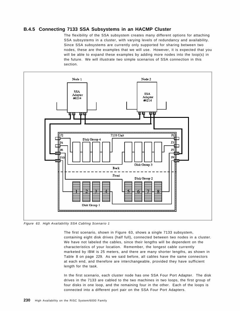
B.4.5 Connecting 7133 SSA Subsystems in an HACMP ClusterThe flexibility of the SSA subsystem creates many different options for attachingSSA subsystems in a cluster, with varying levels of redundancy and availability.Since SSA subsystems are currently only supported for sharing between twonodes, these are the examples that we will use. However, it is expected that youwill be able to expand these examples by adding more nodes into the loop(s) inthe future. We will illustrate two simple scenarios of SSA connection in thissection.
Figure 63. High Availabil i ty SSA Cabling Scenario 1
The first scenario, shown in Figure 63, shows a single 7133 subsystem,containing eight disk drives (half full), connected between two nodes in a cluster.We have not labeled the cables, since their lengths will be dependent on thecharacteristics of your location. Remember, the longest cable currentlymarketed by IBM is 25 meters, and there are many shorter lengths, as shown inTable 8 on page 229. As we said before, all cables have the same connectorsat each end, and therefore are interchangeable, provided they have sufficientlength for the task.
In the first scenario, each cluster node has one SSA Four Port Adapter. The diskdrives in the 7133 are cabled to the two machines in two loops, the first group offour disks in one loop, and the remaining four in the other. Each of the loops isconnected into a different port pair on the SSA Four Port Adapters.
230 High Availability on the RISC System/6000 Family

In this configuration, LVM mirroring should be implemented across the twoloops; that is, a disk on one loop should be mirrored to a disk on the other loop.Mirroring in this way will protect you against the failure of any single disk drive.
The SSA subsystem is able to deal with any break in the cable in a loop byfollowing the path to a disk in the other direction of the loop, even if it does gothrough the adapter on the other machine. This recovery is transparent to AIXand HACMP.
The only exposure in this scenario is the failure of one of the SSA Four PortAdapters. In this case, the users on the machine with the failed adapter wouldlose their access to the disks in the 7133 subsystem. The best solution to thisproblem is to add a second SSA Four Port Adapter to each node, as shown inFigure 64 on page 232. However, this adds an amount of cost to the solutionthat might not be justifiable, especially if there is a relatively small amount ofdisk capacity involved.
An alternative solution would be to use HACMP′s Error Notification feature toprotect against the failure. You could define an error notification method, whichis triggered on the AIX error log record on the failure of the adapter, and whichwould run a script to shut down the cluster manager in a graceful with takeovermode. This would migrate the users to the other node, from which they wouldstill have access to the disks.
HACMP′s Error Notification facility is described, with examples, in 6.8, “AIX ErrorNotification” on page 172.
Our second scenario, in Figure 64 on page 232, shows a second SSA Four PortAdapter added to each node. This allows each system to preserve its access tothe SSA disks, even if one of the adapters were to fail. This solution does leavean adapter port pair unused on each adapter. These could be used in the futureto attach additional loops, if the remaining disk locations in the 7133 were filled,and if additional 7133 subsystems were added into the loops.
Appendix B. Disk Setup in an HACMP Cluster 231

Figure 64. High Availabil i ty SSA Cabling Scenario 2
Any of the loops can be extended at any time, by reconnecting the cabling toinclude the new disks in the loop. If these additions are planned correctly, andcables are unplugged and plugged one at a time, this addition of disks can bedone in a “hot-pluggable” way, such that the system does not have to bebrought down, access to existing disks is not lost, and the new disks can beconfigured while the system continues running.
B.4.6 AIX ′s View of Shared SSA Disk SubsystemsThe AIX operating system configures each disk drive in a shared SSA subsystemas a separate hdisk device on each node.
232 High Availability on the RISC System/6000 Family
Appendix C. Measurements of Disk Reliability
One of the components most prone to failure in any single system or cluster isthe disk drive. In this appendix, we will see how to interpret the reliability ratingof a disk and how it relates to the probability of a drive failing.
C.1 Mean Time Between Failure (MTBF)Mean time between failure (MTBF) is widely used as a reliability measure bysuppliers of small-form-factor disk drives and is regarded throughout the industryas an effective gauge of reliability. However, it is important that you be able tointerpret the relationship between MTBF claims and actual drive reliability.
In general, higher MTBF correlates with fewer drive failures; but an MTBF claimis not a guarantee of product reliability and does not represent a condition ofwarranty.
C.1.1 Defining Mean Time Between FailureMTBF is the mean of a distribution of product life times, often estimated bydividing the total operating time accumulated by a defined group of drives withina given time period, by the total number of failures in that time period.
The defined group of drives is a group of drives that:
• Have not reached end-of-life (typically five to seven years)
• Are operated within a specified reliability temperature range under specifiednormal usage conditions
• Have not been damaged or abused
A failure is any event that prevents a drive from performing its specifiedoperations, given that the drive meets the group definition described above.
This includes drives that fail during shipment and during what is frequentlyreferred to as the early life period (failures typically resulting from manufacturingdefects).
It does not include drives that fail during integration into Original EquipmentManufacturer (OEM) system units or as a result of mishandling, nor does itencompass drives that fail beyond end-of-life.
C.1.2 Mean Time Between Failure and Actual Failures.If you purchase a drive with an MTBF of one million hours (114 years), it doesnot mean that the drive will operate without failure for that period of time. Thatis because the drive will reach end-of-life before reaching one million hours.
For example, a continuously operated drive with a five-year useful life will reachend-of-life in less than 45000 hours. But, theoretically, if the drive is replaced bya new drive when it reaches end-of-life, and the new drive is replaced withanother new drive when it reaches end-of-life, and so on, then the probabilitythat a million hours would elapse before a failure occurs would be greater than30 percent in most cases.
Copyright IBM Corp. 1995 233

Let us now consider the case of multiple drives. If you purchase 1000 driveswith an MTBF of a million hours each, let us calculate the number of disks thatyou can expect to fail over a five-year period.
Assuming that any failed drive is replaced with a new drive having the samereliability characteristics and that the drives are used continuously, then thenumber of failures, r, you can expect is:
Note!
In this example because of statistical variation, there is approximately a 90percent probability that the actual number of failures will be between 33 and55.
If the drives are operated for 16 hours per day instead of 24 hours per day, thenthe number of failures you can expect is:
C.1.3 Predicted Mean Time Between FailureIt is very costly and time-consuming to actually measure high MTBF′s with areasonable degree of precision. Therefore, to assess the reliability of a new diskdrive prior to volume production, reliability data from past products andcomponent and assembly tests is merged to create a mathematical model of thedrive reliability characteristics. The outcome of this modeling process is thepredicted MTBF.
After volume production gets under way, actual field failure data is used to checkthe validity of the model. If you buy drives that have a predicted MTBF of amillion hours and these drives meet the conditions stated earlier in the definitionof a defined group, it is quite likely that these drives will actually achieve amillion hours MTBF.
234 High Availability on the RISC System/6000 Family

The actual MTBF measured from any specific set of drives will depend on theusage and the environmental conditions the drives experience. Stressing a drivebeyond normal usage conditions may reduce the actual MTBF to a point belowthe predicted MTBF.
Some of the conditions under which MTBF, and consequently reliability, of adrive may reduce are:
• Warm environments with poor airflow
• A high seek rate operational environment
• Being part of portable equipment, and hence, subject to higher levels ofshock and vibration
Furthermore, because MTBF can only be measured using statistical methods,any measurement will be subject to statistical variation. The degree of variationis inversely proportional to the number of drives included in the measurement.
C.1.4 Comparison of MTBF FiguresThere are no established industry standards for calculating or reporting MTBF.So, while comparing MTBF figures for drives produced by different vendors, youmust ensure that the assumptions behind the claims are the same.
C.2 Cumulative Distribution Function (CDF)Cumulative Distribution Function (CDF) is a mathematical function using whichyou can define the probability that a drive will fail prior to some point in time.For example, a drive with a CDF equal to four percent at five years has a fourpercent chance of failing sometime within its first five years of operation.
CDF can also be used to determine the number of expected failures from agroup of drives. For example, say that 1000 drives are put into servicesimultaneously. If the CDF equals four percent at five years, then four percent,or 40, drives can, on average, be expected to fail after five years. It should benoted that if, when a drive fails, it is replaced with a new drive, the total numberof failures over the five year period will, on average, be higher than 40 sincesome of the replacement drives may also fail.
Appendix C. Measurements of Disk Reliabil ity 235

236 High Availability on the RISC System/6000 Family

List of Abbreviations
ADSM/6000 Adstar Distributed StorageManager/6000
AIX Advanced InteractiveExecutive
APAR Authorized Program AnalysisReport
The description of a problemto be fixed by IBM defectsupport. This fix is deliveredin a PTF (see below).
ARP Address Resolution Protocol
ASCII American Standard Code forInformation Interchange
AS/400 Application System/400
CDF Cumulative DistributionFunction
CD-ROM Compact Disk - Read OnlyMemory
CLM Cluster Lock Manager
CLVM Concurrent Logical VolumeManager
CPU Central Processing Unit
CRM Concurrent ResourceManager
DE Differential Ended
DLC Data Link Control
DMS Deadman Switch
DNS Domain Name Service
DSMIT Distributed SystemManagement Interface Tool
FDDI Fiber Distributed DataInterface
F/W Fast and Wide (SCSI)
GB Gigabyte
GODM Global Object Data Manager
GUI Graphical User Interface
HACMP High Availabil ity ClusterMulti-Processing
HANFS High Availability Network FileSystem
HCON Host Connection Program
IBM International BusinessMachines Corporation
I/O Input/Output
IP Interface Protocol
IPL Initial Program Load (SystemBoot)
ITSO International TechnicalSupport Organization
JFS Journaled Filesystem
KA Keepalive Packet
KB Kilobyte
kb kilobit
LAN Local Area Network
LU Logical Unit (SNA definition)
LUN Logical Unit (RAID definition)
LVM Logical Volume Manager
MAC Medium Access Control
MB Megabyte
MIB Management InformationBase
MTBF Mean Time Between Failure
NETBIOS Network Basic Input/OutputSystem
NFS Network File System
NIM Network Interface Module
Note: This is the definition ofNIM in the HACMP context.NIM in the AIX 4.1 contextstands for NetworkInstallation Manager.
NIS Network Information Service
NVRAM Non-Volatile Random AccessMemory
ODM Object Data Manager
PAD PacketAssembler/Disassembler
POST Power On Self Test
PTF Program Temporary Fix
A fix to a problem describedin an APAR (see above).
RAID Redundant Array ofIndependent (or Inexpensive)Disks
RISC Reduced Instruction SetComputer
SCSI Small Computer SystemsInterface
SLIP Serial Line Interface Protocol
Copyright IBM Corp. 1995 237

SMIT System ManagementInterface Tool
SMP Symmetr ic Multi-Processor
SMUX SNMP (see below) Multiplexor
SNA Systems NetworkArchitecture
SNMP Simple Network ManagementProtcol
SOCC Serial Optical ChannelConverter
SPOF Single Point of Failure
SPX/IPX Sequenced PackageExchange/Internetwork PacketExchange
SRC System Resource Controller
SSA Serial Storage Architecture
TCP Transmission Control Protocol
TCP/IP Transmission ControlProtocol/Interface Protocol
UDP User Datagram Protocol
UPS Uninterruptible Power Supply
VGDA Volume Group DescriptorArea
VGSA Volume Group Status Area
WAN Wide Area Network
238 High Availability on the RISC System/6000 Family

Index
Special Characters/etc/f i lesystems
fi lesystem helper 188jfslog 186
/etc/inittabcluster problems 190entries 190IP takeover 190run level 190
/ tmp fi lesystempermissions 191
Numerics9333 optical extender cabling RPQ 719333 Serial-Link Disk Subsystem
benefits 70compatibility with SCSI-2 72use with HACMP/6000 33
9334 SCSI Disk Subsystemuse with HACMP/6000 32
Aabbreviations 237acronyms 237AIX
dynamic kernel 12update facilit ies 13
application server definit ion 119ARP cache
Clinfo 191hardware address swapping 113, 191IP takeover 191
asynchronous trap option, clinfo 203automated operations 22availabi l i ty
availabil i ty continuum 6base availabil ity 3continuous availabil ity 4features of AIX 11high availabil i ty 4importance of 2improved availabi l i ty 4levels of 3measurements of 7single system 11techniques to enhance 19threats to 6
Bbad block relocation 12
boot adapter 34, 113
Ccabling
7134-010 High Density SCSI Disk Subsystem 2177135-110 or 7135-210 RAIDiant Array 2197137 Model 412, 413, 414, 512, 513, and 514 Disk
Array Subsystems 2217204 Model 315, 317, and 325 External Disk
Drives 2147204-215 External Disk Drive 2139333 Serial-Link Subsystems 2249334-011 and 9334-501 SCSI Expansion Units 215
cascading resource groups 42, 120change management 21
additional communications connectivity 180additional fi lesystems 179cluster maintenance 179cluster verif ication 176new applications 180software fixes 176software upgrades 176
clinfo (also see HACMP/6000) 30, 37clstat program 55cluster lock manager (also see HACMP/6000) 30cluster manager
changing startup parameters 167cycles_to_fail 166failure detection rates 168HACMP/6000 Version 2.1 166HACMP/6000 Version 3.1 168KA_rate 168missed_KA 168normal_ka_cycles 166pinning 171startup parameters 166
cluster manager (also see HACMP/6000) 29cluster shutdown modes 49cluster tuning 159cluster.log file 53concurrent resource groups 44config_too_long event 53Configuration Manager (cfgmgr) 13cross mount 123cycles_to_fail 166, 168
Ddeadman switch (DMS)
crash command 160disabling 165false takeover 160I/O pacing 163keepalive packets 160
Copyright IBM Corp. 1995 239

deadman switch (DMS) (continued)sync daemon 164timeout 162, 169t imer 160
disk mirroring 4, 12mirroring with RAID 17quorum 184root volume group 180
dual-active configuration 196
Eerror detection 13error notif ication 172events
cluster status events 53customization 55logfiles 53network events 50node events 49
Ffail_standby event 51failure rate 8false take-over
deadman switch 160pinning the Cluster Manager 171
fault tolerance 5, 25fi lesystem helper 188forced shutdown 50fsck Command 12
Ggraceful shutdown 49graceful shutdown with takeover 49
HHACMP
clinfo 30, 37cluster lock manager 30cluster manager 29disk space requirements 60hardware requirements 30network interface 29network interface types 34shared disk devices 29shared SCSI disk setup 90
HACMP/6000 Version 2.1changing startup parameters 167startup parameters 166
HACMP/6000 Version 3.1failure detection rates 168
hacmp.out file 54hardware address swapping 113hot pluggable disk drive 4, 15
hot standby configuration 46
II/O Pacing 162
deadman switch 163use of 163
IP takeoverARP cache 191
isolation
Jjfslog 12join_standby event 53journaled filesystem (jfs) 12
/etc/f i lesystems 186logform 97, 188
KKA_rate 168keep-alive packetskeepalive packets 29, 87
Llock value block 206logical volume
name conflict 187Logical Volume Manager (LVM) 11lvlstmajor command 96
Mmajor fai lure 200major number 96Mean Time Between Failure
definit ion 8minor fai lure 200missed_KA 168multi-tailed disks 15mutual takeover configuration 47
Nnetwork interface (see HACMP)Network Interface Module (NIM) 108NFS cross mount 123NIM (Network Interface Module) 108node environment definit ion
application server definit ion 119resource group definition 120
node isolation 111normal_ka_cycles 166, 167
Ooutage, planned and unplanned 2
240 High Availability on the RISC System/6000 Family

Ppassthru terminator cable 65permissions
/tmp fi lesystem 191phantom disks 189power supply
backup power supply 14power conditioning 14Uninterruptible Power Supply (UPS) 14
private network 35, 113problem management 22public network 35, 113
Qquorum 182
disk mirroring 184volume group descriptor area 181, 184
RRAID disk arrays 15recovery t ime 8redundancy 15Request for Price Quotation (RPQ)
9333 optical extender cabling 71resource group definition 120resource groups
cascading 42concurrent 44rotating 43
rotating resource groups 43rotating standby configuration 46
SSCSI reserveserial network 35, 113serial networks 80Serial Storage Architecture (SSA) 73service adapter 34, 113service level 1
service level management 22shared disk cabling
7134-010 High Density SCSI Disk Subsystem 2177135-110 or 7135-210 RAIDiant Array 2197137 Model 412, 413, 414, 512, 513, and 514 Disk
Array Subsystems 2217204 Model 315, 317, and 325 External Disk
Drives 2147204-215 External Disk Drive 2139333 Serial-Link Subsystems 2249334-011 and 9334-501 SCSI Expansion Units 215
shared logical volumename conflict 187
shared volume groups 15shutdown modes 49
single point of failuredefinit ion 4
single points of failure, eliminating 26Small Computer Systems Interface (SCSI)
arbitrat ion 63spatial reuse 75standby adapter 34, 113swap_adapter event 51Symmetric Multi-Processor (SMP) 59sync daemon 164
deadman switch 164I/O buildup 164
System Management Interface Tool (smit) 11System Resource Controller (SRC) 13
starting Cluster Manager 165system test environment 21systems management
automated operations 22capacity management 20change management 21isolation 23operations management 20performance management 22problem management 22recovery management 23service level management 22skil ls management 20system test environment 21
Ttakeover
disk 38IP address 38
target mode, SCSI 78, 80third-party takeover configuration 47time synchronization 192t imeserver 192tuning
false takeover 159I/O pacing 162kernel lock 162LED 888 159system I/O 162when to do 159
UUninterruptible Power Supply (UPS) 4, 14unstable_too_long event 53upgrade of cluster from HACMP/6000 Version 2.1 to
HACMP/6000 Version 3.1 131
VVGDA 181volume group descriptor area 181
Index 241


ITSO Technical Bulletin Evaluation RED000
International Technical Support OrganizationHigh Availability on the RISC System/6000 FamilyOctober 1995
Publication No. SG24-4551-00
Your feedback is very important to help us maintain the quality of ITSO Bulletins. Please fill out thisquestionnaire and return it using one of the following methods:
• Mail it to the address on the back (postage paid in U.S. only)• Give it to an IBM marketing representative for mailing• Fax it to: Your International Access Code + 1 914 432 8246• Send a note to [email protected]
Please rate on a scale of 1 to 5 the subjects below.(1 = very good, 2 = good, 3 = average, 4 = poor, 5 = very poor)
Overall Satisfaction ____
Organization of the bookAccuracy of the informationRelevance of the informationCompleteness of the informationValue of illustrations
____________________
Grammar/punctuation/spell ingEase of reading and understandingEase of finding informationLevel of technical detailPrint quality
____________________
Please answer the following questions:
a) If you are an employee of IBM or its subsidiaries:
Do you provide billable services for 20% or more of your time? Yes____ No____
Are you in a Services Organization? Yes____ No____
b) Are you working in the USA? Yes____ No____
c) Was the Bulletin published in time for your needs? Yes____ No____
d) Did this Bulletin meet your needs? Yes____ No____
If no, please explain:
What other topics would you like to see in this Bulletin?
What other Technical Bulletins would you like to see published?
Comments/Suggestions: ( THANK YOU FOR YOUR FEEDBACK! )
Name Address
Company or Organizat ion
Phone No.

Cut or FoldAlong Line
Cut or FoldAlong Line
ITSO Technical Bulletin Evaluation RED000SG24-4551-00 IBML
Fold and Tape Please do not staple Fold and Tape
NO POSTAGENECESSARYIF MAILED IN THEUNITED STATES
BUSINESS REPLY MAILFIRST-CLASS MAIL PERMIT NO. 40 ARMONK, NEW YORK
POSTAGE WILL BE PAID BY ADDRESSEE
IBM International Technical Support OrganizationDepartment JN9, Building 821Internal Zip 283411400 BURNET ROADAUSTIN TXUSA 78758-3493
Fold and Tape Please do not staple Fold and Tape
SG24-4551-00


IBML
Printed in U.S.A.
SG24-4551-00