high efficiency tower clean systems
TRANSCRIPT

1
eTCX Features and Benefits:• 99% filtration efficiency of solids down to 25 micron
(2.6 Specific Gravity) and larger greatly reduces suspended solids in recirculated cooling tower water; significantly improving equipment life and removing food source for biological activity
• Minimize tower nozzle clogging, protect basin floor from under-deposit corrosion, eliminate risk of injury associated with manual basin cleaning, and greatly reduce heat transfer loss in downstream equipment
• Control panel supports both Solids Recovery Vessel (SRV) and Automated Purge (EFS/ABV) allowing users the option to convert their system from an SRV to ABV/EFS - Eliminating the need to change the control panel.
• NEMA Premium 1750RPM TEFC motor provides superior efficiency, greater returns on investment, and meets most urban noise abatement levels
• Electric fail-safe valve (EFS) eliminates manual purging and automatically closes valve in event of power failure
• eHB HydroBooster water nozzles operate as low as 10psi. 50% less psi than our standard HydroBoosters; reducing need for larger pumps
• Solids Recovery Vessel (SRV) offers zero water loss and helps meet waste/chemical disposal requirements. eTCX System features SRV-833 - a larger SRV allowing for fewer bag changes
High Efficiency Tower Clean SystemsAutomatically Keep Cooling Tower Basins Clean
LAKOS High Efficiency eTCX Tower Clean Systems help keep the cooling tower basin free of suspended solids that cause scale, corrosion, fouling and biological activity.
Controlling these factors leads to lower maintenance, improved chemical effectiveness, longer cooling tower and downstream equipment life, and a significant decrease in long-term water and energy costs.
Side Stream Closed LoopBasin Sweeping
FILTRATION APPLICATIONS:
Zero Water Loss Options
Available
Zero Maintenance
Options Available
MAINTENANCESOLIDS METERWATER USAGE
25µm
5µm
44µm
74+µm
High
Med
Low
Micron Removalµm (microns)
FLOW RATES:
Basin Sweeping: 50 – 910 US gpm (11 – 206 m3/hr)Side Stream: 65 – 810 US gpm (15 – 184 m3/hr)
Maximum Pressure Rating: 150 psi (10.3 bar)Maximum Fluid Operating Temperature: 100°F (37.8° C) Contact factory for high temperature models
2
0%
10%
20%
30%
40%
50%
60%
70%
80%
90%
100%
32+ µm 23-32 µm 16-22 µm 11-15 µm 1-10 µm
Perf
orm
ance
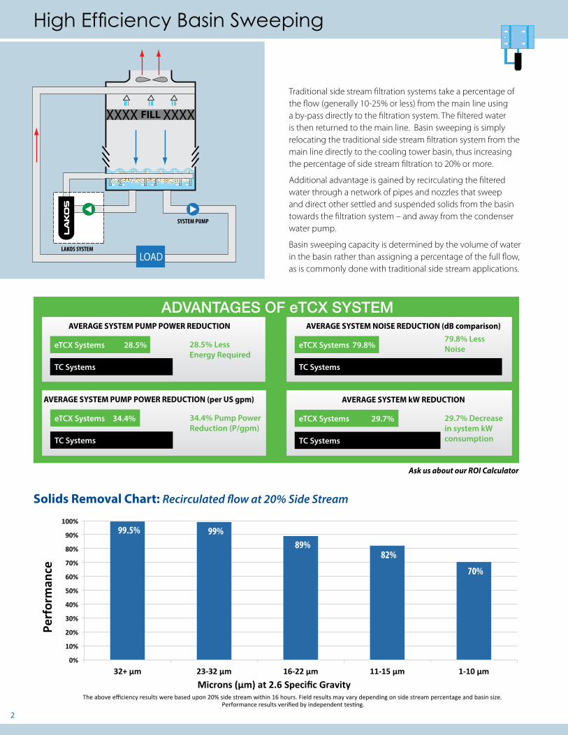
Microns (µm) at 2.6 Specific GravityThe above efficiency results were based upon 20% side stream within 16 hours. Field results may vary depending on side stream percentage and basin size.
Performance results verified by independent testing.
High Efficiency Basin Sweeping
ADVANTAGES OF eTCX SYSTEMAVERAGE SYSTEM PUMP POWER REDUCTION AVERAGE SYSTEM NOISE REDUCTION (dB comparison)
AVERAGE SYSTEM kW REDUCTION
eTCX Systems 28.5% eTCX Systems 79.8%
eTCX Systems 29.7%
TC Systems TC Systems
TC Systems
28.5% Less Energy Required
79.8% Less Noise
29.7% Decrease in system kW consumption
AVERAGE SYSTEM PUMP POWER REDUCTION (per US gpm)
eTCX Systems 34.4%
TC Systems
34.4% Pump Power Reduction (P/gpm)
LAKOS SYSTEM
SYSTEM PUMP
LOAD
XXXX XXXXFILL
Traditional side stream filtration systems take a percentage of the flow (generally 10-25% or less) from the main line using a by-pass directly to the filtration system. The filtered water is then returned to the main line. Basin sweeping is simply relocating the traditional side stream filtration system from the main line directly to the cooling tower basin, thus increasing the percentage of side stream filtration to 20% or more.
Additional advantage is gained by recirculating the filtered water through a network of pipes and nozzles that sweep and direct other settled and suspended solids from the basin towards the filtration system – and away from the condenser water pump.
Basin sweeping capacity is determined by the volume of water in the basin rather than assigning a percentage of the full flow, as is commonly done with traditional side stream applications.
99.5% 99%89%
82%
70%
Solids Removal Chart: Recirculated flow at 20% Side Stream
Ask us about our ROI Calculator

3
eHB HydroBoosters™
HydroBoosters in action
TC Systems in Aulani Disney Hawaii Resort, Hawaii USA HydroBooster Layout at Roseburg Forest Products, California USA
ToTowerClean
System
Filtered water to downstream to chillers/ heat exchangers
Contaminantsare directed toeTCX System
Filtered water�ows to LAKOSHydroBoosters
Cooling Tower
Tower Basin Sweeping witheTCX System and
eHB HydroBoosters
LAKOS eTCX System removes and collects solids
6x induced flow rate activity 1 US gpm entersHydroBooster
eHB HydroBoosters operate at 10psi. 50% less than our standard HydroBoosters
Directed turbulence maximizes cleaning efficiency in the tower basin/remote sump. LAKOS eHB HydroBoosters provide that turbulence with patented vortexing action. Consult LAKOS for technical assistance in basin sweeping layout and piping options.
Basin Cleaning in a Factory Packaged Tower Basin Sweeping in a Field Erected Tower
• Start with a clean basin.
• Required submergence of 2” above centerline inlet of HydroBoosters.
• Position the HydroBoosters to direct solids toward the filtration system’s pump intake and away from any other system pump suction areas.
• Use a closed-loop header in order to equalize the pressure to each HydroBooster.
• Eliminate weirs, baffles or other devices which may promote settling or dead spots within the sump.
• Where possible, take advantage of any existing slopes to direct solids toward the low end of a sump.
• When possible, position the system’s pump intake where solids are most likely to enter the sump.
LAYOUT, HYDROBOOSTER
CTSWEEP -NTS 1 OF 1
ALLYN T 02/11/13
CTS
WE
EP1
-
-
spacial & illustrative purposes only.
CONCEPTUAL DRAWINGCONCEPTUAL DRAWINGCONCEPTUAL DRAWINGCONCEPTUAL DRAWINGCONCEPTUAL DRAWINGThis drawing is submitted for
Do not pre-plumb to these
4. SCHEDULE 40/80 PVC PIPE RECOMMENDED WHERE APPLICABLE.
1. HYDROBOOSTERS TO BE FLUSH WITH BOTTOM OF BASIN.2. ALL DIMENSIONS TO BE FIELD VERIFIED BEFORE INSTALLATION.3. FLOODED SUCTION REQUIRED BEFORE STARTING TC PACKAGE.
dimensions.
NOTES:
2" CLIPEYELET
1/2"MPT X 3/4"NPTFHYDROBOOSTER ADAPTER
(28) HB-10-K HYDROBOOSTER W/ADAPTER(28) HBC-10-200 2" CLIP
EQUIPMENT:
TCX-0280-SRV
LAKOS REP:
LAKOS RSM:
PROJECT:
HB-10-K
DRILL 9/16" HOLETHRU PIPE TOACCEPT MALESTUB OF CLIP
3/4"SOC X 3/4"NPTF
3/4" PIPE BY OTHERS
2" CLIPEYELET
VERTICAL INSTALLATION
3/4" PIPE (CUT TO FIT)
3/4" 90° ELBOW
2" PVC PIPESCH 40
1/2"MPT X 3/4"FPT
2" CLIPEYELET
HB-10-K
HB-10-K
1/2"MPT X 3/4"NPTFHYDROBOOSTER ADAPTER
5. MULTIPLE TOWERS USING ON TC PACKAGE REQUIRE EQUALIZER PIPING BETWEEN EACH TOWER.
LAKOS FILTRATION
Installation Best Practices
LAKOS Separators & Systems must be installed downstream of the main System Pump. Do not install on the suction side of the main system pump. Flow must be pushed through the separator and not pulled. Consult LAKOS for questions.

4
Dual Tower Switching for Light Solids Loading
LAKOS recommends one eTCX basin sweeping system per cell for maximum energy savings and reduced life-cycle costs.
When short term budget needs demand, eTCX systems also provide the benefit of filtering two cooling tower cells alternately – without operator input.
SYSTEM PUMP
LOAD
XXXX XXXXFILL XXXXXXXX FILL
LAKOS SYSTEM SYSTEM PUMP
LOAD
x x
xx
Alternating Kit Features and Benefits:• Provides primary and stand-by tower filtration
• Use one filtration system to clean two cooling tower cells alternately. Economical basin sweeping solution for applications with light solids loading
• Utilized when filtration requirements have larger horsepower (HP) needs and the environment is such that it will allow for smaller HP systems to alternate between cells
• Automated valve switching operation eliminates manual switching in dual cell tower configurations
LAKOS Multi-Tower Basin Cleaning Control Panel
NEMA4x Enclosure
Actuator/Valve Assemblies
Layout Drawing
LAKOS SYSTEM
To ActuatorValves
Cooling Tower 1
Basin SweeperPiping
Cooling Tower 2 Cooling Tower 3 Cooling Tower 4
LEGEND
LAKOS Pump
LAKOS Multi-TowerBasin CleaningControl Panel
1. All wiring, conduit, and fittings from the control panel to the actuator/valve assemblies to be sized and provided by others. 2. Multi-Tower Basin Cleaning control panel is powered separately from the LAKOS Filtration system.
Actuator Valves
Actuator Valves
5
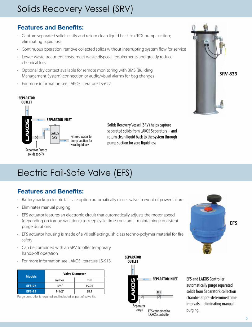
Features and Benefits:• Battery backup electric fail-safe option automatically closes valve in event of power failure
• Eliminates manual purging
• EFS actuator features an electronic circuit that automatically adjusts the motor speed (depending on torque variations) to keep cycle time constant – maintaining consistent purge durations
• EFS actuator housing is made of a V0 self-extinguish class techno-polymer material for fire safety
• Can be combined with an SRV to offer temporary hands-off operation
• For more information see LAKOS literature LS-913
SRV-833
Electric Fail-Safe Valve (EFS)
EFS
Features and Benefits:• Capture separated solids easily and return clean liquid back to eTCX pump suction;
eliminating liquid loss
• Continuous operation; remove collected solids without interrupting system flow for service
• Lower waste treatment costs, meet waste disposal requirements and greatly reduce chemical loss
• Optional dry contact available for remote monitoring with BMS (Building Management System) connection or audio/visual alarms for bag changes
• For more information see LAKOS literature LS-622
Solids Recovery Vessel (SRV)
SEPARATOR INLET
Separator Purgessolids to SRV
SEPARATOROUTLET
Filtered water to pump suction for zero liquid loss
LAKOSSRV
Solids Recovery Vessel (SRV) helps capture separated solids from LAKOS Separators – and return clean liquid back to the system through pump suction for zero liquid loss
ModelsValve Diameter
inches mm
EFS-07 3/4” 19.05
EFS-15 1-1/2” 38.1
Purge controller is required and included as part of valve kit.
SEPARATOR INLET
EFS connected toLAKOS controller
SEPARATOROUTLET
EFS
Separator purge
EFS and LAKOS Controller automatically purge separated solids from Separator’s collection chamber at pre-determined time intervals – eliminating manual purging.

6
HydroBoosters™Model Connection Size Extension Pipe Size (minimum) Input Flow Input PSI
eHB ½” (12.7mm) male NPT ¾” (19.05mm) 10 US gpm(2m3/hr)
10 psi
NOTE: These flow rates are based on an input pressure of 10psi (.68 bar). Minimum water level above centerline of HydroBooster should be 2 inches (50.8 mm).
Inlet/Outlet Premium Butterfly Valve KitsModel Inlet Valve Sizes Outlet Valve Sizes
eTCV models 2.5” to 8” Flanged Butterfly Valves 1.25” to 4” Butterfly Valves 1.25” and 1.5” models are NPT ball valves
High Efficiency Side Stream and Closed Loop Cleaning
Side Stream Closed Loop
BENEFITS:• Economical filtration solution
• Large or variable flow application where full flow is not an option and basins are not accessible
• Reduce suspended solids in main line flow
• Easy to retrofit
• Zero liquid loss options with LAKOS Solids Recovery Vessel
• Zero filtration maintenance when using LAKOS automated purge valves
BENEFITS:• Side stream filtration to remove solids generated in
closed loops
• Zero liquid (water or coolant) loss with Solids Recovery Vessel
• Direct replacement for side stream bags or spiral wound cartridges
XXXX XXXXFILL
LAKOS SYSTEM
LOAD
SYSTEM PUMP
XXXX XXXXFILL
LOAD
SYSTEM PUMP
LAKOS SYSTEM
Condenser
Evaporator
Closed loop Filtration, Data Center, Virginia USA
Side Stream Filtration, Parkland Hospital, Texas USA

7
Models & Dimensions
Basin Sweeping ConfigurationFlow Rate = Basin square footage
Models eHTXSeparators
Flow Rates1 Diffuser/Strainer inlet4
Separator outlet
System WeightPump HP/kW2 Full Load Amperage3
US gpm m3/hr lbs kgs 208V 230V 460V 575VeTCX-0050-SRV eHTX-0025 50 11 2-1/2” 1-1/4” 558 264 2 HP/1.48 kW 5.6 5.1 2.52 2.1eTCX-0080-SRV eHTX-0040 80 18 2-1/2” 1-1/2” 568 257 3 HP/2.23 kW 8.3 7.5 3.9 3.1eTCX-0110-SRV eHTX-0060 110 25 3” 2” 683 309 3HP/2.23 kW 9 8.4 4.2 3.4eTCX-0160-SRV eHTX-0080 160 36 4” 2-1/2” 832 377 5 HP/3.72 kW 13.9 13.4 6.7 5.4eTCX-0210-SRV eHTX-0090 210 48 4” 3” 875 396 7.5 HP/5.59 kW 21 19 9.3 7.5eTCX-0310-SRV eHTX-0140 310 70 6” 4” 1109 502 7.5 HP/5.59 kW 21 18.8 9.4 7.5eTCX-0410-SRV eHTX-0185 410 93 6” 4” 1233 555 10 HP/7.45 kW 25.4 24 12 9.6eTCX-0610-SRV eHTX-0260 610 138 6” 4” 1859 845 20 HP/14.8 kW 50.9 46 23 18.4eTCX-0910-SRV5 eHTX-0320 910 206 8” 6” 2493 1133 25 HP/18.7 kW 66 60 30 24
Side Stream and Closed Loop ConfigurationFlow Rate is critical to system performance. Select model based on Side Stream Flow Rates. LAKOS recommends 20% Side Stream
Models eHTX Separators
Flow Rates1 Diffuser/Strainer inlet4
Separator outlet
System WeightPump HP/kW2 Full Load Amperage3
US gpm m3/hr lbs kgs 208V 230V 460V 575VeTCX-0050-SRV eHTX-0025 65 15 2-1/2” 1-1/4” 558 267 2 HP/1.48 kW 5.6 5.1 2.52 2.1eTCX-0080-SRV eHTX-0040 95 22 2-1/2” 1-1/2” 568 257 3 HP/2.23 kW 8.3 7.5 3.9 3.1eTCX-0110-SRV eHTX-0060 140 32 3” 2” 683 309 3HP/2.23 kW 9 8.4 4.2 3.4eTCX-0160-SRV eHTX-0080 210 48 4” 2-1/2” 832 377 5 HP/3.72 kW 13.9 13.4 6.7 5.4eTCX-0210-SRV eHTX-0090 250 57 4” 3” 875 396 7.5 HP/5.59 kW 21 19 9.3 7.5eTCX-0310-SRV eHTX-0140 365 83 6” 4” 1109 502 7.5 HP/5.59 kW 21 18.8 9.4 7.5eTCX-0410-SRV eHTX-0185 450 114 6” 4” 1233 555 10 HP/7.45 kW 25.4 24 12 9.6eTBX-0610-SRV eHTX-0260 610 138 6” 4” 1644 747 10 HP/7.45 kW 25.4 24 12 9.6eTBX-0810-SRV5 eHTX-0320 810 184 8” 6” 2227 1012 15 HP/11.2 kW 41 37 18.5 14.8
NOTES: All eTCX models are available in PLUS system configurations for filtration down to .35 microns. 1 Higher flow rates available. Contact LAKOS. 2 Models 0050 and 0080 use 3500RPM. 3 Contact LAKOS for motor specific FLA. 4 Minimum suction pipe size is equivalent to system’s diffuser inlet. Pump NPSHR and piping to-and-from LAKOS Systems should be reviewed and sized accordingly. Consult LAKOS for design assistance if length of suction line is more than 25’ or has several elbows or elevation changes. 5 eTCX-0810 and eTBX-0810 units are 22 1/2 deg. low profile
Since active and directed circulation of basin/sump liquid is required for effective solids removal, model selection for the LAKOS eTCX System is based upon the size of the basin or remote sump. This is best determined with these calculations:
For Packaged Cooling Towers
For Remote Sumps with Water Depth Greater than 3 ft**
FlowRate =
Lengthof Basin
(feet)X
Widthof Basin
(feet)X 1 gpm/ft2
2.44 m3/hr/m2
FlowRate =
Lengthof Basin
(feet)X
Widthof Basin
(feet)X 1.5 gpm/ft2
3.66 m3/hr/m2
After determining the basin size using the formula to the right, refer to the flow rate column below.
Select a model that has an equal or larger flow rate. Flow rates larger than those below are available. Please consult LAKOS.
Basin Sweeping Model Selection
Dimensions
ModelsDim A Dim B Dim C
inches mm inches mm inches mmeTCX-0050-SRV 24 610 39-3/4 1010 38-15/16 989eTCX-0080-SRV 29-1/2 749 45 1143 45-1/4 1149eTCX-0110-SRV 29-1/2 749 45 1143 50-11/16 1287eTCX-0160-SRV 29-1/2 749 45 1143 59-1/2 1511eTCX-0210-SRV 29-1/2 749 45 1143 66-11/16 1694eTCX-0310-SRV 31-1/2 800 45 1143 76-5/8 1946eTCX-0410-SRV 31-1/2 800 45 1143 82 2083
eTCX/eTBX-0610-SRV 36 914 49-3/4 1264 95-1/2 2426eTCX/eTBX-0810-SRV 46-1/2 1181 123-3/4 3143 67-1/2 1715
Dimensions are for spatial considerations only. Do not pre-plumb based on above dimensions. Contact factory for detailed dimensions.
More detailed CAD drawings and CSI specifications are available at LAKOS.com.
AB
CD
C
B
AA
B
C
D
12345678
8 7 6 5 4 3 2 1
E
F
E
F
REV
1351
40D
135140SHEET 1 OF 1
eTCX-0210-SRV, TC SYSTEM, HI EFF SWEEPER eHTX-0090, 3/60/460V
UNLESS OTHERWISE SPECIFIED:
SCALE: 1:10 WEIGHT: 875
REVDWG. NO.
DSIZE
TITLE:
NAME DATE
COMMENTS:
Q.A.
MFG APPR.
ENG APPR.
CHECKED
DRAWN
FINISH
MATERIAL
INTERPRET GEOMETRICTOLERANCING PER:
DIMENSIONS ARE IN INCHESTOLERANCES:FRACTIONALANGULAR: MACH BEND TWO PLACE DECIMAL THREE PLACE DECIMAL
APPLICATION
USED ONNEXT ASSY
PROPRIETARY AND CONFIDENTIALTHE INFORMATION CONTAINED IN THISDRAWING IS THE SOLE PROPERTY OF<INSERT COMPANY NAME HERE>. ANY REPRODUCTION IN PART OR AS A WHOLEWITHOUT THE WRITTEN PERMISSION OF<INSERT COMPANY NAME HERE> IS PROHIBITED.
eHTX Separator
PE Pump
304SS Skid
8
LAKOS Corporation, headquartered in Fresno California since 1972, is recognized worldwide for engineering, manufacturing and marketing the original centrifugal action solids from liquids separator and being the world-wide leader in cyclonic separation technology.
LAKOS Separators are manufactured in the USA.
1365 North Clovis AvenueFresno, CA 93727
www.lakos.com
Tel: (559) 255-1601
LS-910I (Rev. 2/21)LAKOS is a proud and contributing member of ASHRAE for over 30 years
LAKOS Separators are manufactured and sold under one or more of the following U.S. Patents: 5,320,747; 5,338,341; 5,368,735; 5,425,876; 5,578,203; 5,622,545; 5,653,874; 5,894,995; 6,090,276; 6,143,175; 6,167,960; 6,202,543; 7,000,782; 7,032,760 and corresponding foreign patents, other U.S. and foreign patents pending.
LAKOS® and HydroBoosters™ are trademarks of LAKOS Corporation
eTCX system components are warranted for one (1) year from date of delivery. If installed 6 months or more after ship date, warranty shall be a maximum of 18 months from ship date. eHTX separators are warranted for five (5) years from date of delivery. For detailed warranty information visit http://www.lakos.com
Independent Testing
LAKOS Separators have been independently tested and certified by an independent testing agency, the International Center for Water Technology (ICWT), confirming our separators’ filtration performance and capability to remove troublesome particle matter from pumped water.
For over 30 years the internationally recognized ICWT/CIT Testing Laboratories have been providing independent, third party testing to a wide range of irrigation and other industries around the world.
ICWT has experience with hydraulics, pumps, filters, and valves. Fluid component testing provides manufacturers, distributors and end-users with accurate performance data for applicability assessment and enable product development. ICWT was recently certified by IAPMO R&T - North America’s premier third party certification body for plumbing and mechanical products. More information about the testing agency and testing process can be found at www.californiawater.org.
Limited Warranty
This product series is warranted to be free of defects in material or workmanship, given the following terms:
LAKOS Separator: 5 years
All other components: 12 months from date of installation; if installed 6 months or more after ship date, warranty shall be a maximum of 18 months from ship date.
If a fault develops, notify us, giving a complete description of the alleged malfunction. Include the model number(s), date of delivery and operating conditions of subject product(s). We will subsequently review this information and, at our option, supply you with either servicing data or shipping instruction and returned materials authorization. Upon prepaid receipt of subject product(s) at the instructed designation, we will then either repair or replace such product(s), at our option, and if determined to be a warranted defect, we will perform such necessary product repairs or replace such product(s) at our expense.
This limited warranty does not cover any products, damages or injuries resulting from misuse, neglect, normal expected wear, chemically-caused corrosion, improper installation or operation contrary to factory recommendation. Nor does it cover equipment that has been modified, tampered with or altered without authorization.
No other extended liabilities are stated or implied and this warranty in no event covers incidental or consequential damages, injuries or costs resulting from any such defective product(s).