high-frequency switch power supply module
TRANSCRIPT

High-frequency switch power supply module
Instruction
Shijiazhuang TonHe Electronics Technologies Co.,Ltd

TonHe High-frequency switch power supply module
1
Index Chapter 1 Overview……………………………………………………………………...2
1.1 Preface………………………………………………………………………………2
1.2 Main characteristic of the modules……………………………………….2
1.3 Type nomination…………………………………………………………………….5
1.4 Technical characteristics…………………………………………………………...6
Chapter 2 Operating Conditions…………………………………………………...8
Chapter 3 Module configuration………………………………………………….8
3.1 Operating diagram of the charging module……………………………………….8
3.2 Dimension……………………………………………………………………………9
3.3 Installation of module……………………………………………………………...14
3.4 Operation Introduction……………………………………………………………16
Appendix…………………………………………………………………………………….20
Chapter 2 Operating Condition…………………………………………………...8
Chapter 3 Module’s configuration……………………………………………….8
3.1 Operating diagram of the charging module……………………………………….8
3.2 Dimension……………………………………………………………………………9
3.3 Installation of module……………………………………………………………...14
Appendix…………………………………………………………………………………….20

TonHe High-frequency switch power supply module
2
Chapter 1 Overview
1.1 Preface
“TH” series intelligent high-frequency switch power supply modules are specially
developed to meet the demands of modern DC system. The charger rectifiers are
designed with world leading patent technology “resonant voltage type soft switching
power supply technology”. They feature high efficiency and stability, intelligent control,
small size and light weight.
Two ranges available: 220V and 110V series with a variety of options separately. RS-485
interface, easy to connect with automation system for various transformer substations,
power plant, hydraulic power plant and other DC power supply applications.
The third-generation modules (-3 Model) are improved by LED display and plastic
injection molding front panels. Here are the options and specifications as below:
1.2 Main characteristic of the Modules
Modular design, N+1 pc(s) backup;
The friendly man-machine interface. LED screen
RS-485 communication interface, achieves “4 remote control” function
Model Output voltage
(V)
output current
(A) cooling type
Dimensions
(D×H×W mm)
TH230D05ZZ-3 220 5 natural cooling 260×179×109
TH230D07ZZ-3 220 7 natural cooling 325×230×130
TH230D10ZZ-3 220 10 natural cooling 325×230×130
TH230D20ZZ-3 220 20 natural cooling 400×323×146
TH230D20NZ-3 220 20 fan cooling 357×218×118
TH230D30NZ-3 220 30 fan cooling 410×303×136
TH230D40NZ-3 220 40 fan cooling 410×303×136
TH110D10ZZ-3 110 10 natural cooling 260×179×109
TH110D20ZZ-3 110 20 natural cooling 325×230×130
TH110D40ZZ-3 110 40 natural cooling 400×323×146

TonHe High-frequency switch power supply module
3
High efficiency, up to 95%-96%;
Light weight, Small size
After the full bridge rectifying circuit rectifies 3-phase AC to DC, then adjusted by
reactive PFC, power factor>0.94;
Unequal current ratio of parallel connection<+/-3%, can ensure twenty modules work
well by parallel connection.
Function against reverse connection
LED digital screen
Output overvoltage protection
To prevent the disastrous accident caused by output overvoltage, there is overvoltage
protection circuit in the module. Once the output voltage is higher than the threshold,
the module locks up automatically and fault indication light is on, the faulty module quits
work automatically and doesn’t affect the normal operation of the entire system. The
overvoltage protection threshold is set in the factory, 320V±5% for 220V series, 160V
±5% for 110V series.
Output current limiting protect
The output current cannot increase infinitely. The maximum output current of is limited to
105% of the rated output current.
Output short-circuit protection
When short circuit, the output voltage drops to 0 immediately. Limit the short circuit
current under 15% of rated output current. The module will not be damaged under short
circuit state for a time, and resumes to work automatically after debugging.
Fig.1-1 Output Characteristic

TonHe High-frequency switch power supply module
4
Module parallel protection
There is parallel protection circuit in each module to ensure that when the fault module
quits the system, the normal work of other modules and the system won’t be effect.
Over-temperature protection: Over-temperature protection is mainly for protecting
large power components. In particular case, when the temperature of the radiator is over
the threshold 85℃, the charger module shuts down automatically to protect itself and
resume to work after the temperature comes lower.
Output over-current protection
The output current cannot increase infinitely. If overloaded, the output voltage decreases
automatically to protect the power components. The over current protection can be
resumed automatically.
1.3 Type No. Naming
TH Series number 3:
公司名称: 通合
Abbreviation of company name “Tonghe”
Fig.1-2 output of module parallel
rated output current:05、07、10、20、30、40
module:D is electric power module
range of the output voltage
230 for 220V electric power module;
110 for 110V electric power module
ZZ:natural cooling module;
NZ:fan cooling module

TonHe High-frequency switch power supply module
5
1.4 Technical characteristics
TH230D -3 series module characteristic of the module technical index
Module Code
project 230D05ZZ-3 230D07ZZ-3 230D10ZZ-3 230D20ZZ-3 230D20NZ-3 230D30NZ-3 230D40NZ-3
rated output current(A) 5 10 10 20 20 30 40
power(KW) 1.5 2.1 3 6 6 9 12
weight(kg) 5.2 9 9 16 10.5 19 19
cooling type natural cooling fan cooling
Internal radiator temperature
rise ≤30℃ ≤20℃
range of input
voltage AC
(VAC)
min 304
Typical value 380
max 456
range of the
output voltage
(VDC)
min 190
Typical value 220
max 300
Voltage Stabilizing accuracy ±0.5%
Current Stabilizing accuracy ±1%
PFC ≥0.93
Efficiency ≥95%
noise(dB) <50
Storage
temperature
(℃)
min -40
Typical value 25
max 60
working
temperature
(℃)
min -10
Typical value 25
max 40
Unbalance rate of load sharing ≤±3%
Soft start time(s) 3~8
Ripple coefficient ≤0.2%
Load grade Continuous working with Grade I(100%) rating output current
Automatic current limiting
The output current does not increase infinitely. When output current is over
threshold, there will be limited constant current output. The maximum output
current of is limited to 105% of the rated output current.
Output overvoltage protection No output, threshold (320±5VDC), self recoverable
output short circuit protection When short circuit, the module will protect itself from broken. Self recoverable

TonHe High-frequency switch power supply module
6
TH110D -3 series module characteristic of the module technical index
module
project 110D10ZZ-3 110D20ZZ-3 110D40ZZ-3
rated output current(A) 10 20 40
power(KW) 1.5 3 6
weight(kg) 5.2 9 16
cooling type natural cooling
heat sink temperature rise ≤30℃
rang of input
AC(VAC)
min 304
Typical value 380
max 456
rang of the
output
voltage
(VDC)
min 95
Typical value 110
max 150
Voltage Stabilizing accuracy ±0.5%
Current Stabilizing accuracy ±1%
PFC ≥0.93
Efficiency ≥95%
noise(dB) 50
Storage
temperature
(℃)
min -40
Typical value 25
max 60
working
temperature
(℃)
min -10
Typical value 25
max 40
Unbalance rate of load sharing ≤±3%
Soft start time(s) 3~8
Ripple ≤0.2%
Load Continuous working with Grade I(100%) rating output current
Automatic current limiting
The output current does not increase infinitely. When output current is
over threshold, there will be limited constant current output. The
maximum output current of is limited to 105% of the rated output current.
Output overvoltage protection No output, threshold (160±3VDC), self recoverable
output short circuit protection When short circuit, the module will protect itself from broken. Self recoverable

TonHe High-frequency switch power supply module
7
Chapter 2 Operating Condition
1. Altitude 2000m;
2. Storage temperature: -40℃~+60℃; ambient temperature: -10C ~ 40C;
3. Relative humidity: 96%(operating temperature 25C);
4. No conductive and explosive dust, no caustic gas;
5. Indoor only;
Chapter 3 Module Configuration
3.1 Working flow of the charging module
380VAC input
Input protection
Pull bridge rectifier circuit
reactive
filtering
High frequency Transformer
High frequency Rectifier circuit
Output protection
DC output
Soft switch resonance loop
Over-voltage
short-circuit
over-current
Over-temperature
module parallel
Feedback sampling
Microprocessor
RS 485 LED
Functional diagram

TonHe High-frequency switch power supply module
8
3.2 Dimension
TH230D05ZZ-3、TH110D10ZZ-3 natural cooling module dimension sketch map:
Front panel Back view
outline drawing of the module

TonHe High-frequency switch power supply module
9
TH230D10ZZ-3、TH110D20ZZ-3 natural cooling module dimension sketch map:
front panel back view
outline drawing of the module

TonHe High-frequency switch power supply module
10
TH230D20ZZ-3、TH110D40ZZ-3 natural cooling module dimension sketch map:
front panel back view
outline drawing of the module

TonHe High-frequency switch power supply module
11
TH230D20NZ-3 fan cooling module dimension sketch map:
front panel back view
outline drawing of the module

TonHe High-frequency switch power supply module
12
TH230D30NZ-3、TH230D40NZ-3 fan cooling module dimension sketch map:
front panel back view
outline drawing of the module

TonHe High-frequency switch power supply module
13
3.3 Installation
1. TH230D05ZZ-3、 TH230D07ZZ -3、TH230D10ZZ -3、TH230D20ZZ-3 、TH110D10ZZ-3、
TH110D20ZZ-3、TH230D20NZ-3,
Definition of the connector assembly(JMD29T)
2.
port Standard pins Definition Function
1 12# DC+ DC output+
2 12# DC- DC output-
26 12# G EARTH
27 12# A Input 380V
28 12# B Input 380V
29 12# C Input 380V
Note:
① Undefined port is empty
② Keep a good natural ventilation around the charger module.
② Keep a good ventilation around the fan cooling modules
③ Connect according to the indication “current share +”, “current share -” to achieve the
automatic current share.
④ Wire terminal A and terminal B separately and connect with the host monitor (such as
THJK002G-3 monitor) through terminal A & terminal B of RS485 A, which achieve
communication between the module and monitor

TonHe High-frequency switch power supply module
14
3. TH230D40NZ-3、TH110D40ZZ-3、TH230D30NZ-3:
Definition of connector (JMD29T)
port Standard
pins definition function
1、3 12# DC+ DC output+
2、4 12# DC- DC output-
26 12# G EARTH
27 12# A Input380V
28 12# B Inptu380V
29 12# C Input 380V
③ Undefined port is empty
④ Keep a good natural ventilation around the charger module.
⑤ Keep a good ventilation around the fan cooling modules
⑥ Connect according to the indication “current share +”, “current share -” to achieve the
automatic current share.
⑦ Wire terminal A and terminal B separately and connect with the host monitor (such as
THJK002G-3 monitor) through terminal A & terminal B of RS485 A, which achieve
communication between the module and monitor

TonHe High-frequency switch power supply module
15
For installation, there are brackets for option, installation drawing is in the appendix
3.4 Operation Introduction
Take TH230D10ZZ-3 as the example
Figure 4-1 Front panel of charging module
3.4.1 DIP OPERATION INSTRUCTION
Two options: Information Inquiry and Parameter Set, choose via the “Auto”&”Manual”
DIP Switch. It is “Information Inquiry” when the DIP on top side and is “Parameter Set”
when at the bottom side.
TonHe High-frequency switch power supply module
16
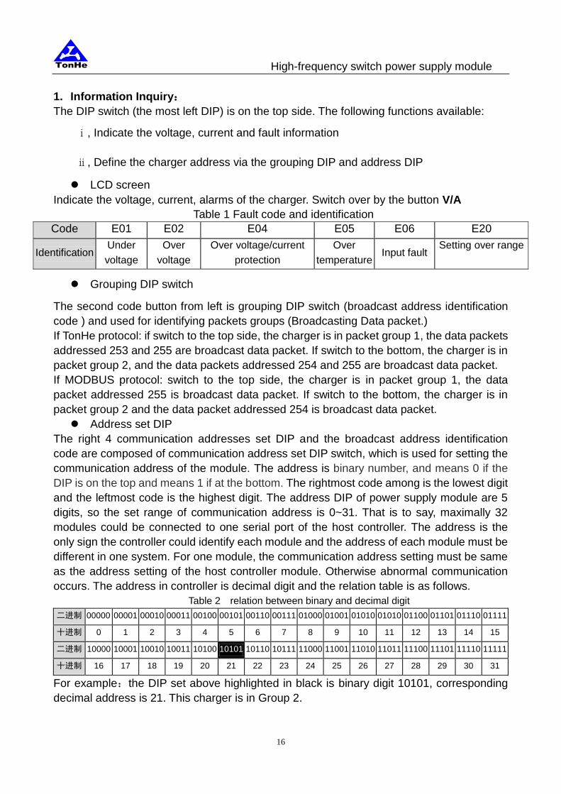
1. Information Inquiry:
The DIP switch (the most left DIP) is on the top side. The following functions available:
ⅰ, Indicate the voltage, current and fault information
ⅱ, Define the charger address via the grouping DIP and address DIP
LCD screen
Indicate the voltage, current, alarms of the charger. Switch over by the button V/A
Table 1 Fault code and identification
Code E01 E02 E04 E05 E06 E20
Identification Under
voltage
Over
voltage
Over voltage/current
protection
Over
temperature Input fault
Setting over range
Grouping DIP switch
The second code button from left is grouping DIP switch (broadcast address identification
code ) and used for identifying packets groups (Broadcasting Data packet.)
If TonHe protocol: if switch to the top side, the charger is in packet group 1, the data packets
addressed 253 and 255 are broadcast data packet. If switch to the bottom, the charger is in
packet group 2, and the data packets addressed 254 and 255 are broadcast data packet.
If MODBUS protocol: switch to the top side, the charger is in packet group 1, the data
packet addressed 255 is broadcast data packet. If switch to the bottom, the charger is in
packet group 2 and the data packet addressed 254 is broadcast data packet.
Address set DIP
The right 4 communication addresses set DIP and the broadcast address identification
code are composed of communication address set DIP switch, which is used for setting the
communication address of the module. The address is binary number, and means 0 if the
DIP is on the top and means 1 if at the bottom. The rightmost code among is the lowest digit
and the leftmost code is the highest digit. The address DIP of power supply module are 5
digits, so the set range of communication address is 0~31. That is to say, maximally 32
modules could be connected to one serial port of the host controller. The address is the
only sign the controller could identify each module and the address of each module must be
different in one system. For one module, the communication address setting must be same
as the address setting of the host controller module. Otherwise abnormal communication
occurs. The address in controller is decimal digit and the relation table is as follows.
Table 2 relation between binary and decimal digit
二进制 00000 00001 00010 00011 00100 00101 00110 00111 01000 01001 01010 01010 01100 01101 01110 01111
十进制 0 1 2 3 4 5 6 7 8 9 10 11 12 13 14 15
二进制 10000 10001 10010 10011 10100 10101 10110 10111 11000 11001 11010 11011 11100 11101 11110 11111
十进制 16 17 18 19 20 21 22 23 24 25 26 27 28 29 30 31
For example:the DIP set above highlighted in black is binary digit 10101, corresponding
decimal address is 21. This charger is in Group 2.

TonHe High-frequency switch power supply module
17
2. Parameter set
Come to parameter setting when switch the left most DIP to the bottom (read 1). Use the
Grouping DIP and right 4 address bits to make different set. The DIP switch and
identifications are as follows.
Table 3 DIP identification (220V/110V)
拨
码
Grouping
DIP 1 2 3 4 Function Setting range Default
0 0 0 0 0 Working mode 0-IND., 1-MANU, 2-AUTO 2
0 0 0 0 1 Communication protocol 0-Modbus,1-TonHe 1
0 0 0 1 0 Over voltage alarm set 220V Under voltage threshold -300V 260V
110V Under voltage threshold-150V 130V
0 0 0 1 1 Under voltage alarm set 220V 190V-over voltage threshold 190V
110V 95V-over voltage threshold 95V
0 0 1 0 0 Charging state set 0-float charge, 1-boost charge 0
0 0 1 0 1 Float charge voltage 220V
型
190V-300V 242V
110V
型
95V-150V 121V
0 0 1 1 0 Boost charge voltage set 220V
型
176V-300V 253V
110V
型
88V-150V 126V
0 0 1 1 1 Charging current limit set 10%-105% rated current 105%
0 1 0 0 0 Current threshold from float
to boost charge
Current threshold from boost to float
charge-105% 80%
0 1 0 0 1 Current threshold from boost
to float charge 0.5-current threshold from float to boost 20%
0 1 0 1 0 Tail current charging time 0-10 hours 3
0 1 0 1 1 Max boost charge time 0-99 hours 10
0 1 1 0 0 Boost charge cycle 0-999 days 180
0 1 1 0 1 Fault output node set 0-normally open 1-normally close 0
NOTE: you need to power on the charger again if you change the communication
protocol on line
When the DIP setting is over the range in the table above, will indicate E20.
If -3G and -5 series products, the low end of voltage range is 176V/88V, the under
voltage alarm default is 176V/88V. The current set range is 10-110% and the highest
current from float to boost charge is 110% rated output current.

TonHe High-frequency switch power supply module
18
The setting operation instruction:
1) Switch the DIP to “MANU” i.e. “1” position, otherwise cannot enter the setting
interface;
2) Follow the tables above to enter setting interface required;
3) Push the button “V/A” once, then the leftmost letter flashes. Now you can adjust the
data;
4) Use the “V ADJ” button “▼,▲” to adjust the value. Push “▼” once, the value
decrease a unit. Push “▲”, increase a unit.
5) Then push “V/A button again to make sure the leftmost letter stop flash. Then the
set finishes and setting is saved successfully.
The working mode of the charger is optional. Three modes optional, Independent,
Automatic,Manual and two communication protocol optional, TH and MODBUS. The RS485
interface available between charger and controller/ charger and charger:
Independent “IND.”: the charger will work independently when set working mode “0”. The
DIP switch position “00000”. Then the communication protocol ”00001“-“1” (“TH” protocol)
will be advised. Under this working mode, the charger cannot communicate with the upper
controller, but the automatic float and boost charge is available. The charger can manage
the charging process automatically. The same time, it is capable to send charging voltage
and current command to control other chargers if several chargers work in parallel.
This mode is suitable for the conditions without upper controller and several chargers work
in parallel. One charger will be “IND.” mode as master module to send command to other
chargers. The other chargers will be set “AUTO” mode and ”TH” protocol.
Manual ”MANU”: set working mode “00000” -“1”, the charger will be Manual mode.
Communication protocol is “TonHe” when the DIP setting “00001”-“1”, is “MODBUS” when
set “00001”-“0”. The user can set accordingly to the upper controller. Under this working
mode, the charger can communicate with the controller and send data back to the controller.
Automatic float and boost charge function is available but the charger can not send
command to other chargers.
This mode is suitable for that the additional controller does not have automatic float and
boost charge function but the controller need to know the working status of chargers.
Normally for system one charger and one battery bank.
Automatic “AUTO”: corresponding DIP set is “00000”-“2”. Communication protocol is
“TonHe” when the DIP setting “00001”-“1”, is “MODBUS” when set “00001”-“0”. If choose
“AUTO” mode, the setting indication in the tables above is null. The charger will work
following the setting of the controller. In this mode, the controller is able to realize “four
remotes”, remote signaling, remote measure, remote control and remote regulating. The
charging voltage and current are controlled by the upper controller.
This mode is suitable for that the upper controller is of automatic float and boost charge
management function and can control the chargers remotely.

TonHe High-frequency switch power supply module
19
Charger set
Communication
protocol of upper
controller
Automatic
float and
boost
charge
function
Remarks
Working
mode Protocol TonHe Modbus
IND.
TonHe
YES
If choose Modbus protocol, the master
charger cannot control the charging
current of other slave chargers. So advise
“TonHe”
Modbus
MANU TonHe YES Remote signaling and measure available
Remote control and regulating unavailable Modbus YES
AUTO TonHe YES
Remote signaling, remote measure,
remote control, remote regulating Modbus YES
NOTE: When the charger work in “AUTO” mode, the output voltage will come to
234V/117V/48V/24V, the current limit threshold will be the max 105% rated current.
Pay attention to the RS485 A&B correspondingly when wiring.
3.4.6 Fault Display
Alarm information are displayed in the table of fault code in the LED. Then LED displays the
fault code. The voltage will be shown by pushing the switching button. Fault code as shown
in Table 4-3.
Table 4-3
fault
code E01 E02 E03 E04 E05 E06
Definition
Output
Under
voltage
Output over
voltage
Output Overflow
protection
Output over
voltage protection
Overheat
protection
Ac input
Abnormal
3.4.7 Communication Function
The module can communicate with PC mode in RS485 interface. It can send the output
voltage and current, the module protection and alarm information to a host computer,
accepting and implementing the control orders issued by the host computer.
Note:When the charging module is in automatic mode, if there is not any
communication in 4 minutes . The output voltage will be adjusted to 234V
automatically. Current limiting points will be open all to 105% of rated current value

TonHe High-frequency switch power supply module
20
Appendix Different type of bracket are available:5A-3 natural cooling, 10A-3 natural cooling
5A-3 natural cooling (Apply to: TH230D05ZZ-3、TH110D10ZZ-3)
① The 2 -rooms bracket opening holes drawing:
The 2 modules brackets installation sketch:

TonHe High-frequency switch power supply module
21
② The 3 rooms bracket open holes drawing:
The 3 -module brackets installation sketch:

TonHe High-frequency switch power supply module
22
2、 10A-3 natural cooling(Apply to: TH230D10ZZ-3、TH110D20ZZ-3)
① The 2 -rooms bracket opening holes drawing:
The 2-rooms brackets installation sketch:

TonHe High-frequency switch power supply module
23
② 3 –rooms bracket opening holes drawing:
The 3- rooms brackets installation sketch

TonHe High-frequency switch power supply module
24
③ 4 -rooms bracket opening holes drawing:
installation sketch: