high functionalization of titanium oxide-based materials
TRANSCRIPT
High functionalization of titanium oxide-based materials
and their application
( )
by
Hideya Hattori
Submitted to Hiroshima University
In partial fulfillment of the requirements for the degree of
Philosophy of Doctor
Supervisor Professor Dr. Tsuneji Sano
Department of Applied Chemistry,
Graduate School of Engineering,
Hiroshima University
September 2018
Referee in Chief : Professor Tsuneji sano
Referees : Professor Takeshi Shiono
Professor Kei Inumaru
Associate Professor Masahiro Sadakane
Department of Applied Chemistry,
Graduate School of Engineering,
Hiroshima University

Chapter 1 Overview
1-1. Titanium oxide as photocatalyst ························································ 1
1-1-1. What is a photocatalyst? ··························································· 1
1-1-2. A brief history of TiO2 photocatalysts and problems
affecting applications ······························································· 4
1-1-3. Improvement of photocatalytic activity:
(1) Visible light responsiveness ·················································· 5
1-1-4. Improvement of photocatalytic activity:
(2) Structural design ······························································· 9
1-1-5. Improvement of photocatalytic activity:
(3) Covering the titanium oxide surface·········································· 11
1-1-6. Improvement of photocatalytic activity:
(4) Designing the reaction environment ·········································· 13
1-2. Application as a sunscreen ······························································ 15
1-2-1. What is a sunscreen? ······························································· 15
1-2-2. A brief history of TiO2-based absorber and problems for application ······· 16
1-3. Objectives of this research ······························································ 20
1-4. References ················································································· 22
Chapter 2 Highly efficient and selective sunlight-induced photocatalytic oxidation of
cyclohexane on an eco-catalyst under a CO2 atmosphere ································· 24
2-1. Introduction ··············································································· 24
2-2. Experimental ·············································································· 28
2-3. Results and discussion ··································································· 30

2-3-1. Characterization of catalysts ······················································ 30
2-3-2. Oxidation of cyclohexane and adsorption of cyclohexanone ················· 32
2-4. Conclusion ················································································· 39
2-5. References ················································································· 40
Chapter 3 Extraordinary effects of argon atmosphere on TiO2 photocatalysis········· 42
3-1. Introduction ··············································································· 42
3-2. Experimental ·············································································· 43
3-3. Results and discussion ··································································· 45
3-4. Conclusion ················································································· 61
3-5. References ················································································· 62
Chapter 4 Ternary modified TiO2 as simple and efficient photocatalyst for green
organic synthesis ·················································································· 64
4-1. Introduction ··············································································· 64
4-2. Experimental ·············································································· 66
4-3. Result and discussion ···································································· 69
4-3-1. Characterization of catalysts ······················································ 69
4-3-2. Photocatalytic and adsorption test ················································ 73
4-4. Conclusion ················································································· 83
4-5. References ················································································· 84
Chapter 5 Efficient and selective photocatalytic cyclohexane oxidation on a layered
titanate modified with iron oxide under sunlight and CO2 atmosphere ··················· 86
5-1. Introduction ··············································································· 86
5-2. Experimental ·············································································· 88
5-3. Result and discussion ···································································· 91
5-3-1. Characterization of catalysts ······················································ 91
5-3-2. Photocatalytic and adsorption tests ············································· 100
5-3-3. Catalytic reaction mechanism ··················································· 105
5-4. Conclusion ··············································································· 107
5-5. References ··············································································· 108
Chapter 6 Enhanced photocatalytic activity of a layered titanate by simply mixing
with TiO2-based photocatalysts as additives ················································ 110
6-1. Introduction ············································································· 110
6-2. Experiment ·············································································· 112
6-3. Result and discussion ·································································· 115
6-3-1. Characterization of addtives and mixtures ···································· 115
6-3-2. Photocatalytic test ································································· 120
6-4. Conclusion ··············································································· 125
6-5. References ··············································································· 126
Chapter 7 Microporous titanate nanofibers for highly efficient UV-protective
transparent coating ·············································································· 128
7-1. Introduction ············································································· 128
7-2. Experiment ·············································································· 130
7-3. Results and discussion ································································· 134
7-3-1. Characterization of products ···················································· 134
7-3-2. Evaluation of optical properties of MPTNF ·································· 145
7-4. Conclusion ··············································································· 152
7-5. References ··············································································· 154
Chapter 8 Summary ·········································································· 158
List of publications ············································································· 161
Acknowledgements ············································································· 162

1
Chapter 1
Overview
1-1. Titanium oxide as photocatalyst
Titanium oxide is abundant, non-toxic, and stable. It is a semiconductor; thus, it is
expected to have various applications in solar power generation, as a photocatalyst, and
in sunscreen. Furthermore, since its characteristics as a photocatalyst were first
discovered by Honda and Fujishima[1], it has drawn attention for use in energy
conversion. In this chapter, I discuss the use of titanium oxide as photocatalyst and as a
UV absorber.
1-1-1. What is a photocatalyst?
A photocatalyst is a substance that acts as a catalyst by absorbing light. Like other
catalysts, the material itself does not change but promotes chemical reactions. Currently,
the most widely studied photocatalytic material is titanium oxide, but, in the 1960's,
zinc oxide was also reported to be a photocatalyst. However, since Honda and Fujishima
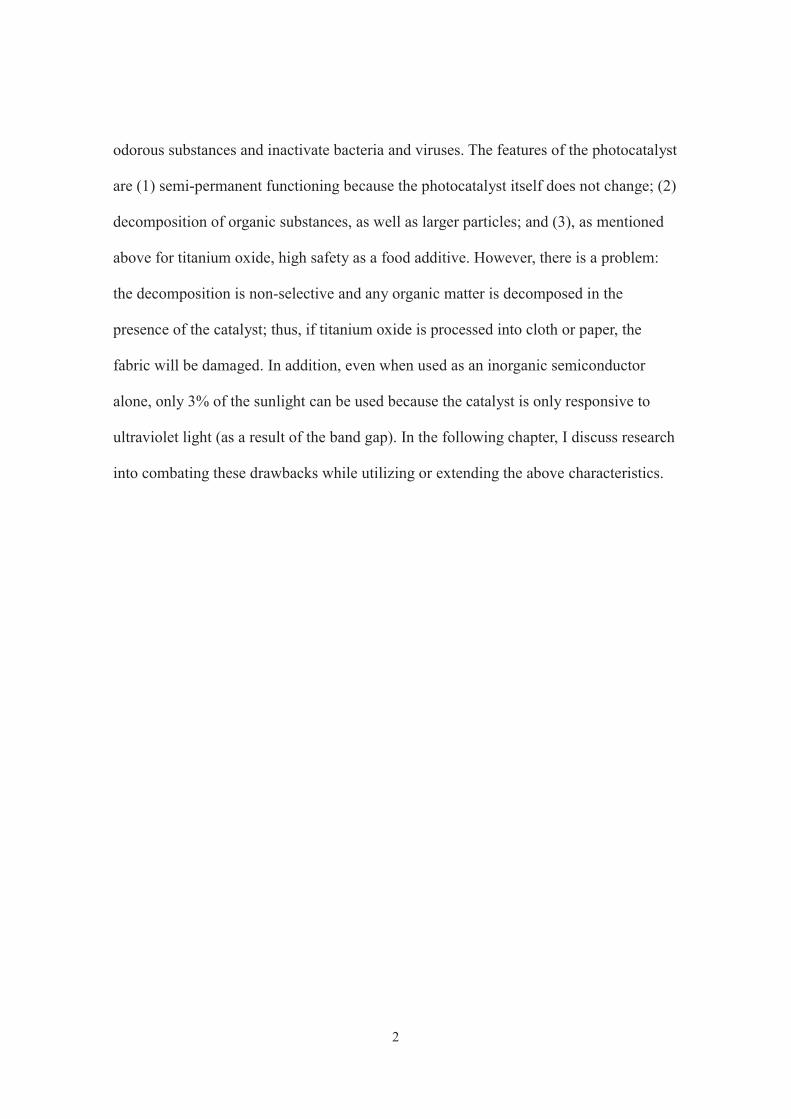
et al. reported the photocatalytic activity of titanium oxide in 1972 (Fig. 1-1) [1],
significant research into titanium oxide has been carried out. In addition, they reported
that TiO2 was stable to light irradiation, putting this new material in the limelight. By
the end of the 1970’s, numerous applications of TiO2 photocatalysis had been reported.
For example, the photodetoxification of HCN [2], ammonia synthesis from N2 and water
[3], the reduction of CO2 [4], and H2 production from carbohydrates and water [5].
In the photocatalytic reaction, the photocatalyst absorbs the ultraviolet light in
sunlight or that produced by a fluorescent lamp, generating active compounds from
oxygen and water. By using these active substances, photocatalysts can decompose
2
odorous substances and inactivate bacteria and viruses. The features of the photocatalyst
are (1) semi-permanent functioning because the photocatalyst itself does not change; (2)
decomposition of organic substances, as well as larger particles; and (3), as mentioned
above for titanium oxide, high safety as a food additive. However, there is a problem:
the decomposition is non-selective and any organic matter is decomposed in the
presence of the catalyst; thus, if titanium oxide is processed into cloth or paper, the
fabric will be damaged. In addition, even when used as an inorganic semiconductor
alone, only 3% of the sunlight can be used because the catalyst is only responsive to
ultraviolet light (as a result of the band gap). In the following chapter, I discuss research
into combating these drawbacks while utilizing or extending the above characteristics.
3
Fig. 1-1 The photocatalytic activity of TiO2 for the decomposition of water.
Nature, 1972, 238, 37.
TiO2
Pt
O2H2
4
1-1-2. A brief history of TiO2 photocatalysts and problems affecting applications
As described above, in 1972, Honda and Fujishima reported water decomposition in
an electrolytic system consisting of water, a platinum electrode, and a titanium oxide
electrode. The reaction proceeded on the irradiation of the titanium oxide electrode with
ultraviolet light in the presence of a slight electric field [1]. After this discovery, it was
found that water decomposition proceeds under ultraviolet light irradiation with
platinum-nanoparticle-supported titanium oxide in the absence of an electric field. Since
these discoveries, the conversion of light energy to chemical energy by semiconductor
photocatalysts has been recognized.
Titanium oxide is thus expected to be an inorganic semiconductor based on the above
properties. It has been extensively studied as a photocatalyst for the complete oxidation
of compounds, as discussed below. However, recently, the production of clean and
inexpensive fuels and simple chemicals using solar energy has drawn attention as an
economical and environmentally friendly synthetic method, and the application of
titanium oxide to this field is also expected. However, although titanium oxide has the
usefulness mentioned above, there are some problems that must be solved before it can
be used for these applications. For example, when titanium oxide is applied as a
photocatalyst for the synthesis of simple chemicals, it lacks oxidative selectivity. In
reactions in an organic solvent, the desired partially oxidized product is nonselectively
sequentially and completely oxidized by the photoexcited radical species. In aqueous
reactions, OH radicals, which are strong oxidizing agents, are generated, and the
oxidation selectivity further decreases. Therefore, in the case of using titanium oxide,
the desired partial oxidation product is easily sequentially and completely oxidized in
both reaction systems, and the product yield and selectivity are low. Thus, the

5
development of novel catalysts for improving the yield and selectivity of partial oxides
has been heavily investigated.
On the other hand, studies of photocatalysts for the decomposition and removal of
harmful organic compounds have been actively conducted since the 1980’s. Many
degradation mechanisms using titanium oxide have also been reported in studies of
water quality and organic soil pollutants, and basic research into titanium oxide has
advanced worldwide [6]. The decomposition or removal of harmful organic compounds
by a photocatalyst is effective for green chemistry because titanium oxide show
catalytic activity on irradiation with the ultraviolet (UV) light in sunlight, as well as
from artificial light sources. Another advantage is that no toxic by-products are formed
during the decomposition process. However, titanium oxide only responds to UV light,
which represents a mere 3% of the light in sunlight. Therefore, its activity is poor and
only low concentrations of contaminants can be removed in the presence of weak indoor
visible light and under sunlight. Similarly, even for atmospheric purification, because
titanium oxide responds only to UV light, volatile organic compounds such as
formaldehyde and toluene can only be removed at low concentrations. Therefore, it is
important to improve the UV photoactivity and to impart visible-light-responsiveness to
enable the decomposition of organic pollutants in high concentrations. In the following
chapters, I introduce representative remedial methods.
1-1-3. Improvement of photocatalytic activity: (1) Visible light responsiveness
For the decomposition/removal of harmful organic compounds, titanium oxide can be
doped with heteroatoms or loaded with precious metals; these methods improve the UV
photoactivity and impart visible light responsiveness. The amount of solar energy that
6
falls on the earth is enormous, but most is unusable. When titanium oxide absorbs light
of energy coincident with the band gap, electron excitation occurs, and electrons move
from the valence band to the conduction band. Then, holes and electrons are formed,
inducing various photocatalytic reactions. Therefore, the band gap is the factor that
controls reactivity. The band gap can be reduced by doping titanium oxide with
heteroatoms. Initially, doping with transition metals was reported. However, in this
method, the absorption in the visible light region is dependent on the impurity level of
the doping element generated in the band gap, so that the recombination of
photogenerated electrons and holes tends to occur and the catalytic activity is low. In
2001, the substitution of nitrogen and sulfur for oxygen (anionic site) in titanium oxide
was found to reduce the band gap and allow visible-light-induced photocatalytic
reactions [7]. Research into visible light operation type photocatalyst has since increased.
However, even with nitrogen doping, although the absorption capacity in the visible
light region improves, the absorption intensity is significantly lower than that for
ultraviolet light. On the other hand, sulfur-doped titanium oxide, in which sulfur is
exchanged with titanium as a cation instead of an anion, has a relatively high absorption
intensity for visible light. Furthermore, in the decomposition of methylene blue, the
photocatalytic activity is higher under visible light or ultraviolet light irradiation than
that of pure titanium oxide. Sulfur-doped titanium oxide showed about 65% of
ultraviolet light activity, even under visible light irradiation [8].
In addition to the application of visible light responsiveness, studies have been
actively carried out using precious metals. Among the noble metal nanoparticles, in
particular, gold nanoparticles can be strongly fixed on the surface of the titanium oxide.
When gold nanoparticles are supported on titanium oxide, gold captures the electrons
7
photoexcited in titanium oxide by ultraviolet light irradiation within femtoseconds and
prevents recombination with the holes; as a result, the separation of photoexcited holes
and electrons on titanium oxide occurs efficiently. Another advantage of gold
nanoparticles for the development of visible-light-responsive photocatalysts is that gold
nanoparticles themselves are visible-light-responsive photocatalysts (Fig. 1-2) [9]. The
strong absorption of visible light by the collective excitation of the surface of gold
nanoparticles has been reported. Silva et al. reported that water decomposition by gold
nanoparticle-supported titanium oxide is activated by irradiation with visible light
(monochromatic 532-nm light) [10]. In this reaction, gold nanoparticles absorb visible
light by surface plasmon resonance and electrons are injected into the conduction band
of titanium oxide; thus, holes are formed in the gold nanoparticles and electrons are
formed in the conduction band of the semiconductor, and these act as active sites. In
addition, radical species, such as superoxide anions, are generated by the reaction of
photogenerated electrons with O2 and hydroxyl radicals are generated by the reaction of
photogenerated holes with OH-. These highly oxidizing compounds are the active
species in the photocatalytic reaction. Based on the above mechanism, photocatalytic
activity is imparted under visible light irradiation. On the other hand, it is known that
gold-nanoparticle-supported titanium oxide exhibits high activity as a photocatalyst for
the synthesis of simple molecules [11, 12].

8
Fig. 1-2 Mechanism of visible light absorbing and visible light activity
of TiO2 and Au-TiO2.
bi d i ibl li h i iChem. Commun., 2004, 1810

9
1-1-4. Improvement of photocatalytic activity: (2) Structural design
By using a porous material as a support, it is also possible to incorporate the unique
properties of the porous material, such as adsorption concentration effects, into the
photocatalytic process. Among the porous materials, novel photocatalysts consisting of
ultrafine titanium oxide fixed in the pores of a zeolite or mesoporous silica, or titanium
oxide species with highly coordinated tetra-coordinated structure of molecular size
incorporated in a framework have been reported to be useful. A nanostructured titanium
oxide photocatalyst is also a useful technique for functional design. For example,
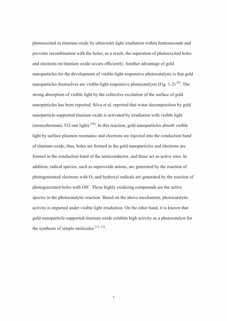
Shiraishi et al. reported the selective oxidation of benzene to phenol using mesoporous
titanium oxide (Fig. 1-3) [13]. It was concluded that benzene (the substrate) is adsorbed
on the catalyst and the sequential and complete oxidation of the product (phenol) is
suppressed by preventing its adsorption, thus promoting selective oxidation. Likewise,
structural design using layered titanates has also been reported. Layered titanates take in
substances between layers by intercalation, and these materials have a specific structure
and function depending on the type and number of functional units between the taken-in
layers; therefore, selective organic synthesis is also possible. Normally, layered titanate
responds only to ultraviolet light, but it can also be applied as a photocatalyst with
visible light activity by incorporating a substance having visible light absorption. For
example, Choy et al. reported the efficient decomposition of organic compounds on a
cluster of chromium oxide having visible light absorption between layers of layered
titanate in water under visible light irradiation [14].
10
Fig. 1-3 Selective oxidation of benzene on mesoporous TiO2.
J. Am. Chem. Soc., 2005, 127, 12820.

11
1-1-5. Improvement of photocatalytic activity: (3) Covering the titanium oxide surface
By covering the surface of titanium oxide with another inorganic semiconductor
material, improvements, such as imparting visible light responsiveness and improving
the selectivity for the target product, can be made. For example, the product selectivity
was improved by coating the surface of titanium oxide with other inorganic oxides.
Tanaka and colleagues achieved the selective oxidation of benzyl alcohol under visible
light irradiation by coating the surface of titanium oxide with a layer of niobium oxide
(Fig. 1-4) [15]. By combining semiconductors with different band gaps, ozonide ions
which are strong oxidizing agents, are formed on titanium oxide, whereas ozonide ions
are not formed by completely covering the titanium oxide surface with niobium oxide;
therefore, sequential/complete oxidation is suppressed. In addition, Shiraishi et al.
achieved the selective oxidation of benzyl alcohol upon irradiation with light having a
wavelength of 350 nm by modifying the titanium oxide surface with tungsten oxide [16].
They reported that the selective partial oxidation reaction progressed after the
modification of tungsten oxide because the reaction between the titanium oxide holes,
which are strongly oxidizing, and benzaldehyde, the desired partial oxidation product,
was suppressed.

12
Fig. 1-4 Selective oxidation by coating the surface of titanium oxide with a layer of
niobium oxide.
ACS Catal., 2012, 2, 175.
13
1-1-6. Improvement of photocatalytic activity: (4) Designing the reaction environment
Improvements in the reaction efficiency and product selectivity for the organic
synthesis and decomposition removal of organic compounds by heterogeneous catalysis
under sunlight irradiation are crucial.
The reaction efficiency can be improved and the product selectivity can be controlled
by careful design of the reaction environment. However, because of the mild reaction
conditions, improvements to the photocatalytic activity by reaction environment design
are rarely reported. Tabata et al. found that water decomposition on a platinum-loaded
titanium oxide was improved by about 800 times for hydrogen generation and about
1500 times for oxygen generation when UV light was irradiated from the top of the
reaction mixture rather than the bottom [17]. Arakawa et al. added sodium carbonate to
the reaction system for the decomposition of water using TiO2-supported platinum as a
catalyst. In this system, Pt is covered with carbonate, so the reverse reaction (formation
of water) on Pt is suppressed; as a result, the hydrogen and oxygen generation efficiency
hydrogen and oxygen is doubled [18].
Naya et al. reported that when a cationic surfactant was added to the solution used for
the visible-light photocatalytic oxidation of primary alcohols to carbonyls on Au/TiO2,
the yield improved by 30 times [19]. In this system, the surfactant covers the surface of
the catalyst, resulting in a hydrophobic surface; thus, the reaction intermediate ions
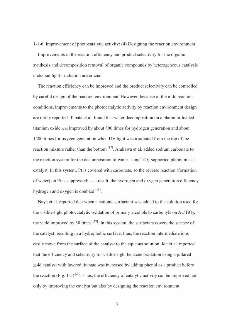
easily move from the surface of the catalyst to the aqueous solution. Ide et al. reported
that the efficiency and selectivity for visible-light benzene oxidation using a pillared
gold catalyst with layered titanate was increased by adding phenol as a product before
the reaction (Fig. 1-5) [20]. Thus, the efficiency of catalytic activity can be improved not
only by improving the catalyst but also by designing the reaction environment.
14
Fig. 1-5 Selective oxidation of benzene to phenol using a catalyst in which gold is
pillared between layered titanate.
J. Am. Chem. Soc., 2010, 132, 16762.
Au disk
OH
OH

15
1-2. Application as a sunscreen
1-2-1. What is a sunscreen?
An ultraviolet absorber is a substance that can absorb sunlight and ultraviolet rays,
resulting in fluorescence, while remaining structurally stable. This prevents damage to
surrounding compounds by converting high energy ultraviolet light into thermal energy
or longer wavelength light. Ultraviolet absorbers are mainly used as stabilizers for
plastics, rubber, paints, and dyes to prevent photodegradation caused by long-term
exposure to sunlight. Ultraviolet absorbers must be non-colored and show excellent
coalescence, heat resistance, and chemical stability, as well as have low volatility.
Ultraviolet rays with a wavelength of 290 nm or less are completely absorbed by the
ozone layer before reaching the ground, but ultraviolet light with a wavelength of 290 to
400 nm reaches the ground and is related to polymer aging. An ultraviolet absorber
selectively absorbs these high-energy ultraviolet rays, converting them into harmless
energy by energy conversion, either releasing or consuming the converted energy.
Although organic ultraviolet light absorbers have drawn attention, inorganic ultraviolet
screening agents have attracted more attention because of concerns about the safety of
organic compounds to the human body. To absorb ultraviolet rays with an inorganic
compound, the band excitation of a semiconductor can be utilized, and a semiconductor
having a band gap energy of about 3 eV is necessary to remove ultraviolet light with a
wavelength of 400 nm or less. In addition, to enhance the transparency of the material, it
is necessary to use fine particles to prevent light scattering. Titanium oxide and zinc
oxide nanoparticles have already been widely used as ultraviolet screening agents, and
the use of nanoparticles of cerium oxide is also being studied. On the other hand,
titanium oxide and zinc oxide are also representative photocatalysts, and it is known
16
that active oxygen species are generated by light irradiation, promptly oxidizing organic
compounds and inactivating bacteria. However, in recent years, oxidative DNA damage
caused by the active oxygen species generated by the photoexcitation of semiconductors
such as titanium has been reported, and, when semiconductor nanoparticles are
incorporated into cosmetic products for skin application, the generation of active
oxygen by the photoexcitation of semiconductor nanoparticles must be considered.
Therefore, taking into consideration the influence on the human body, the development
of materials without photocatalytic activity is required. The ultraviolet absorber must (1)
strongly absorb ultraviolet light (especially ultraviolet light having a wavelength of 290
to 400 nm); (2) be thermally stable, especially during high-temperature processing, and
have low volatility; (3) be chemically stable and not react with other components in the
material; (4) have excellent coalescence and be easily dispersed uniformly in the
material, for example, phenomena such as blooming and exudation should not occur;
(5) not be absorbed, decomposed, or discolored; (6) be colorless, nontoxic, and
odorless; (7) tolerate immersion and washing; and (8) be low cost and easy to obtain.
Titanium-oxide-based ultraviolet light absorbers having these necessary properties have
been developed and are introduced in the next chapter.
1-2-2. A brief history of TiO2-based absorber and problems for application
Titanium oxide is expected to be a UV-absorbing coating material that can be
dispersed in a versatile polymer. Irradiation with UV light not only destroys DNA,
suppresses the immune system, and causes skin aging, but also decomposes and
degrades plastics, pigments, dyes, and organic compounds, such as wood and paper,
used in general purpose equipment. Thus, protection against UV radiation has received
17
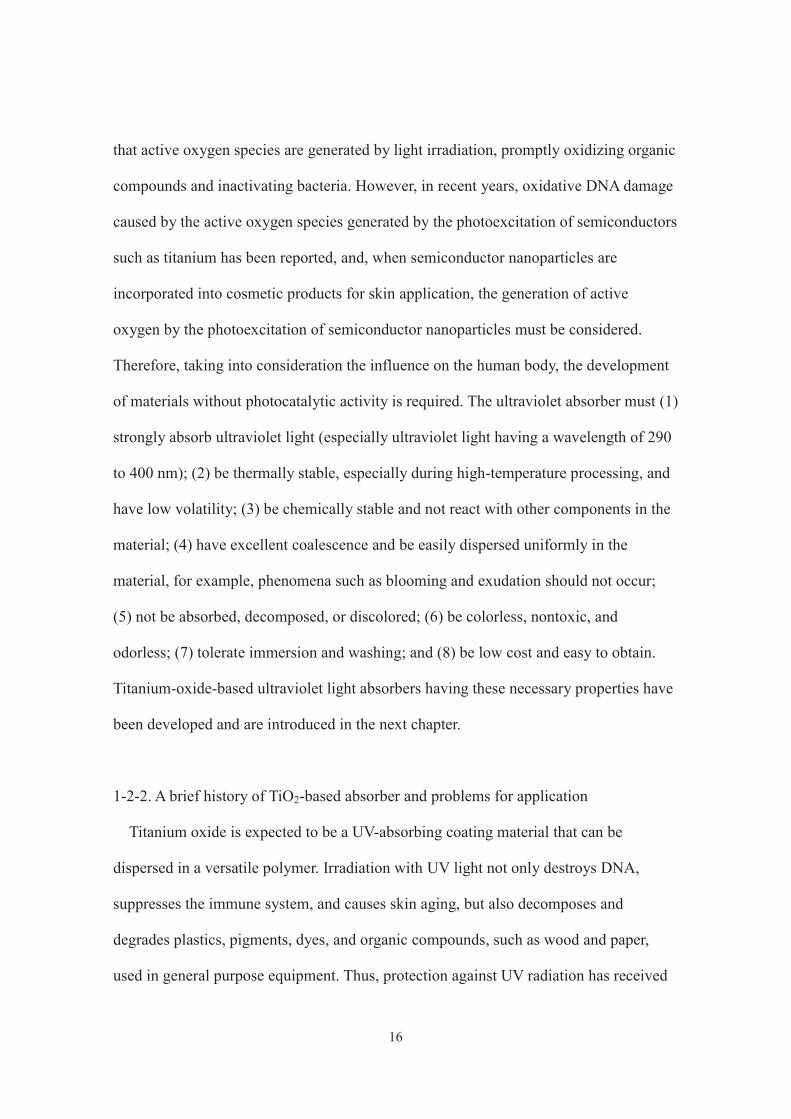
attention from science and industry. Organic UV-light-absorbing materials dispersed in a
polymer have been used as UV-light-protecting layers for organic materials because
they convert the absorbed light energy into thermal energy through a photophysical
process, preventing damage (Fig. 1-6) [21, 22]. However, the polymer may be
decomposed by the excited state of the absorbing material when exposed to UV
radiation. Therefore, application of these materials has been limited [23]. The high
refractive index and high UV photoactivity of titanium oxide are major problems when
it is applied as a UV-absorbing coating material. Because of the high refractive index,
the polymer matrix whitens and loses permeability, and the high UV photoactivity
causes degradation and decomposition of the polymer. To solve these problems, the use
of fine particles of titanium oxide, doping of elements with less electron localization
than O2-, and complexation with other inorganic materials have been reported. For
example, Tressaud et al. prepared a new UV-absorbing coating material by fluorine
doping (Fig. 1-7) [24]. This material exhibited light absorption similar to that of anatase,
but the photocatalytic activity was low, and the refractive index of visible light was 1.9.
In addition, Cui et al. prepared, via a sol-gel method, a UV-absorbing coating material
composed of titanium oxide and cerium oxide or silicon oxide [25]. These materials
strongly absorb UV light, and the transmission of visible light was high. Under mild
conditions, crystalline material was obtained, which efficiently absorbed UV light.
Because of these properties, we conclude that even organic materials that are sensitive
to heat can be protected.
18
Fig. 1-6 An organic UV absorber. Chem. Soc. Rev., 2007, 36, 1270.

19
Fig. 1-7 A new UV-absorbing coating material prepared by fluorine doping.
Chem. Mater., 2009, 21, 1275.

20
1-3. Objectives of this research
Based on the above background, titanium oxide has been applied as a photocatalyst
for the synthesis of simple chemicals and for environmental purification, and UV light
absorber. Titanium oxide, which is a promising photocatalyst, was prepared, and I
attempted to achieve visible light responsiveness using inexpensive materials, as well as
to promote the catalytic reaction by controlling the reaction environment. In addition, I
have attempted to prepare new titanium-oxide-based materials for various applications.
I report the preparation method and the applications of this material. This paper consists
of eight chapters.
In Chapter 1, I introduced the utility and problems in applying titanium oxide as a
photocatalyst or UV-light-absorbing material and described the significance of this
paper.
In Chapters 2 and 3, I describe the selective synthesis of simple chemicals and the
removal of harmful substances in water by controlling the reaction environment. In
Chapter 2, the selective synthesis of industrially important simple chemicals is reported.
This was achieved on Fe-grafted titanium oxide with sunlight irradiation under a CO2
atmosphere [26, 27]. The effects of CO2 addition are discussed from various viewpoints.
As reported in Chapter 3, even when using titanium oxide (P25, anatase, and rutile),
efficient decomposition and the removal of harmful organic compounds under sunlight
irradiation was achieved under an Ar atmosphere [28]. Under an argon atmosphere, the
decomposition efficiency was significantly improved compared to other gas
atmospheres, and this is also discussed.
In Chapters 4–6, I describe the reaction efficiency of the new photocatalyst, which
was tuned by design and combination with existing catalysts. In Chapter 4, a novel
21
titanium-oxide-based photocatalyst co-modified with three components (gold, iron, and
nickel), all of which increase the photocatalytic reaction efficiency of titanium oxide, is
reported. This catalyst was efficient for the selective synthesis of simple chemicals
synthesis under sunlight irradiation [29]. In Chapter 5, layered titanate, which is a layered
crystal of titanium oxide composition and a zeolite-like photocatalyst modified with
iron between the interlayers, was designed to achieve efficient and selective chemical
synthesis on irradiation with sunlight [30]. By conducting the reaction under a CO2
atmosphere, as described in Chapter 2, the catalytic activity was further improved. As
reported in Chapter 6, mixing the layered titanate and the titanium-oxide-based
photocatalyst in water resulted in improved reaction efficiency. In addition, in this
chapter, the differences resulting from the different combinations of material types, as
well as the mechanism for the increased efficiency, are discussed [31].
In Chapter 7, I report the successful synthesis of a novel microporous titanium oxide
by the hydrothermal treatment of layered titanates [32]. Because of its unique
nanostructure, it shows little photocatalytic activity and has a considerably lower
refractive index than conventional titanium oxide; thus, it was applied as UV-absorbing
transparent coating material dispersed in a general purpose polymer.
Finally, in Chapter 8, I summarize my findings.
22
1-4. References
[1] A. Fujishima and K. Honda, Nature, 1972, 238, 37.
[2] S. N. Frank and A. J. Bard, J. Am. Chem. Soc., 1977, 99, 303.
[3] G. N. Schrauzer and T. D. Guth, J. Am. Chem. Soc., 1977, 99, 7189.
[4] T. Inoue, A. Fujishima, S. Konishi, and K. Honda, Nature, 1979, 277, 637.
[5] T. Kawai and T. Sakata, Nature, 1980, 286, 474.
[6] I. Matryanov and J. Klabunde, Environ. Sci. Technol., 2003, 37, 3448.
[7] R. Asahi, T. Morikawa, T. Ohwaki, K. Aoki and Y. Taga, Science, 2001, 293, 269.
[8] T. Ohno, T. Mitsui and M. Matsumura, Chem. Lett., 2003, 32, 364.
[9] Y. Tian and T. Tatsuma, Chem. Commun., 2004, 1810.
[10] C. G. Silva, R. Juarez, T. Marino, R. Molinari and H. Garcia, J. Am. Chem. Soc.,
2011, 133, 595.
[11] D. I. Enache, J. K. Edwards, P. Landon, B. Solsona-Espriu, A. F. Carley, A. A.
Herzing, M. Watanabe, C. J. Kiely, D. W. Knight and G. J. Hutchings, Science., 2006,
311, 362.
[12] J. T. Carneiro, C. - C. Yang, J. A. Moma, J. A. Moulijn and G. Mul, Catal Lett.,
2009, 129, 12.
[13] Y. Shiraishi, N. Saito and T. Hirai, J. Am. Chem. Soc., 2005, 127, 12820.
[14] T. Kim, S. G. Hur, S.-J. Hwang, H. Park, W. Choi and J.-H. Choy, Adv. Funct.
Mater., 2007, 17, 307.
[15] S. Furukawa, T. Shishido, K. Teramura and T. Tanaka, ACS Catal., 2012, 2, 175.
[16] D. Tsukamoto, M. Ikeda, Y. Shiraishi, T. Hara, N. Ichikuni, S. Tanaka and T. Hirai,
Chem. Eur. J., 2011, 17, 9816.
[17] S. Tabata, H. Nishida, Y. Masaki and K. Tabata, Catal. Lett., 1995, 34, 245.
23
[18] K. Sayama and H. Arakawa, Chem. Commun., 1992, 150.
[19] S. Naya, M. Teranishi, T. Isobe and H. Tada, Chem. Commun., 2010, 46, 815.
[20] Y. Ide, M. Matsuoka and M. Ogawa, J. Am. Chem. Soc., 2010, 132, 16762
[21] J. Keck, M. Roessler, C. Schroeder, G. J. Stueber, F. Waiblinger, M. Stein, D.
LeGourriérec, H. E. Kramer, H. Hoier, S. Henkel, P. Fischer, H. Port, T. Hirsch, G. Rytz
and P. Hayoz, J. Phys. Chem. B, 1998, 102, 6975.
[22] M. Zayat, P. Garcia-Parejo and D. Levy, Chem. Soc. Rev., 2007, 36, 1270.
[23] P. Garcia-Parejo, M. Zayat and D. Levy, J. Mater. Chem., 2006, 16, 2165.
[24] A. Demourgues, N. Penin, E. Durand, F. Weill, D. Dambournet, N. Viadere and A.
Tressaud, Chem. Mater., 2009, 21, 1275.
[25] Z. Wang, Y. Pan, Y. Song and H. Cui, J. Sol-Gel Sci. Technol., 2009, 50, 261.
[26] Y. Ide, N. Nakamura, H. Hattori, R. Ogino, M. Ogawa, M. Sadakane and T. Sano,
Chem. Commun., 2011, 47, 11531.
[27] Y. Ide, H. Hattori, M. Sadakane and T. Sano, Green Chem., 2012, 14, 1264.
[28] Y. Ide, H. Hattori and T. Sano, Phys. Chem. Chem. Phys., 2014, 16, 7913.
[29] Y. Ide, N. Kawamoto, Y. Bando, H. Hattori, M. Sadakane and T. Sano, Chem.
Commun., 2013, 49, 3652.
[30] H. Hattori, Y. Ide, S. Ogo, K. Inumaru, M. Sadakane and T. Sano, ACS Catal.,
2012, 2, 1910.
[31] H. Hattori, M. Eguchi, Y. Ide and T. Sano, Bull. Chem. Soc. Jpn., 2017, 90, 1276.
[32] H. Hattori, Y. Ide and T. Sano, J. Mater. Chem. A, 2014, 2, 16381.
24
Chapter 2
Highly efficient and selective sunlight-induced photocatalytic oxidation of cyclohexane
on an eco-catalyst under a CO2 atmosphere
2-1. Introduction
Heterogeneous photocatalysis driven by sunlight is a possible way to produce
chemical, medical commodity and fuels in an economically and environmentally
favorable manner. An improvement of the reaction efficiency and selectivity is required
and, accordingly, much effort has been made to design the structure, composition and
morphology of photocatalysts. Titanium dioxide is a promising material for the purpose
due to availability, low toxicity, and chemical stability; however, it responds only to UV
light, occupying 3–4% of sunlight, and tends to be nonselective for synthetic reactions.
After Fujishima et al. reported photocatalytic ability of TiO2 [1], great endeavors are
continuously being done to modify TiO2 by doping with metal [2] and nonmetal elements
[3] or hybridization with organic dyes[4] and nanoparticles,[5] as well as to design novel
catalysts such as molecular-sieve-like TiO2 [6–9] and non-TiO2 materials,[10–14] to achieve
efficient and selective photocatalysis under sunlight. Besides catalyst design, there have
been several studies on the influence of reaction environments on heterogeneous
photocatalysis.
TiO2-supported gold nanoparticles are well known as visible light responsive
photocatalysts. When gold nanoparticles are supported on TiO2, gold nanoparticle
captures photoexcited electrons on TiO2 under UV light irradiation with the speed of fs
and suppresses returning to holes, so separation of holes and electrons of TiO2 is
efficient. Also, since it has been reported that gold nanoparticles strongly absorb visible

25
light due to surface plasmon resonance caused by collective excitation of electrons [15],
it has been widely studied as a visible light responsive photocatalyst. On the other hand,
catalyst combining an inexpensive base metal and TiO2 has also been developed.
Among them, iron is nontoxic and is a metal abundantly present as a resource. However,
doping iron into defects of TiO2 improves visible light activity but reduces ultraviolet
light activity. [16] It is thought that this is because the energy level formed by doping
becomes the site of recombination of electrons and hole. In order to solve this problem,
Tada et al. developed a catalyst which improves not only visible light but also UV light
activity by using a method to modify the surface of TiO2 with iron oxide [17, 18].
Selective oxidation of cyclohexane to cyclohexanone and cyclohexanol is one of the
most important synthetic reactions, since the partially oxidized products are an
important intermediate in ε-caprolactam synthesis, which is used in the manufacture of
nylon polymers. Nonetheless, in the oxidation of cyclohexane which is currently used
industrially, despite the severe reaction conditions of reaction temperature 140 to 160 °
C, and pressure 1 to 1.5 MPa, cyclohexane conversion is 4 to 10%, selectivity of partial
oxide is about 80% [19]. Therefore, an efficient oxidation of cyclohexane with high
conversion and selectivity is required. Oxidation of cyclohexane over TiO2 has been
widely carried out by Herrmann group[20] and Mul group.[21] Some of them report that
partialoxidation of cyclohexane is promoted with high selectivity (> 98%). However, in
these studies, ultraviolet light irradiation is necessary for catalytic activation. On the
other hand, oxidation of cyclohexane using a catalyst activated under visible light
irradiation has also been reported. Shiraishi et al. reported selective cyclohexane
oxidation using molecular oxygen as an oxidizing agent under irradiation with visible

26
light, using Cr / Ti / Si composite oxide as a catalyst [22]. The selectivity of the partial
oxide is 99%, and the reaction mechanism is also mentioned.
As described above, in the synthesis of basic chemicals using heterogeneous catalysts
under sunlight irradiation, new catalysts are actively designed to improve reaction
efficiency and product selectivity. On the other hand, there are some reports that the
reaction efficiency can be improved and the product selectivity can be controlled by
controlling the reaction environment. For example, Arakawa and colleagues added
sodium carbonate to the reaction system of the decomposition of water using
TiO2-supported platinum as a catalyst in order to cover Pt with carbonate, the reverse
reaction of hydrogen and oxygen generated on Pt was suppressed, as a result, the
generation efficiency of hydrogen and oxygen was improved by about 2 times [23]. It
was also reported by Naya and colleagues that when cationic surfactant was added to
the solution in the photocatalytic oxidation reaction of the primary alcohol to carbonyl
compound under visible light irradiation on Au/TiO2, the yield was improved up to
about 30 times [24]. It is proposed that the surfactant covers the surface of the catalyst
and becomes hydrophobic, as a result, the reaction intermediates easily move from the
catalyst surface to the aqueous solution. Ide and colleagues reported that efficiently and
selectively of benzene oxidation using a catalyst in which gold is pillared between
layers of layered titanate under irradiation with visible light by adding phenol as a
product before the reaction. [25] In addition, Ide et al. proposed that partial oxidation
phenol is achieved by preliminarily adding CO2 generated by complete oxidation in the
oxidation reaction of benzene under visible light irradiation using gold fine
particle-supported titanium oxide as a catalyst. [26]

27
Therefore, in this research, I tried to design a new reaction field in which efficient
and selective reactions proceed on known photocatalysts. Partial oxidation reaction of
cyclohexane to cyclohexanone and cyclohexanol, which is an industrially important
reaction, was carried out under simulated sunlight irradiation. Iron-modified TiO2 was
used as a catalyst and the reaction was carried out under a CO2 atmosphere which is a
complete oxidation product.
28
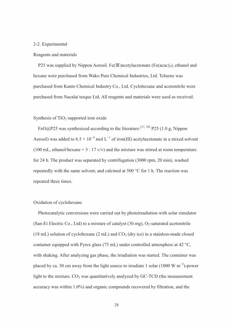
2-2. Experimental
Reagents and materials
P25 was supplied by Nippon Aerosil. Fe( )acetylacetonate (Fe(acac)3), ethanol and
hexane were purchased from Wako Pure Chemical Industries, Ltd. Toluene was
purchased from Kanto Chemical Industry Co., Ltd. Cyclohexane and acetonitrile were
purchased from Nacalai tesque Ltd. All reagents and materials were used as received.
Synthesis of TiO2 supported iron oxide
FeO@P25 was synthesized according to the literature:[17, 18] P25 (1.0 g, Nippon
Aerosil) was added to 6.5 × 10⁻⁴ mol L−1 of iron(III) acetylacetonate in a mixed solvent
(100 mL, ethanol/hexane = 3 : 17 v/v) and the mixture was stirred at room temperature
for 24 h. The product was separated by centrifugation (3000 rpm, 20 min), washed
repeatedly with the same solvent, and calcined at 500 °C for 1 h. The reaction was
repeated three times.
Oxidation of cyclohexane
Photocatalytic conversions were carried out by photoirradiation with solar simulator
(San-Ei Electric Co., Ltd) to a mixture of catalyst (30 mg), O2-saturated acetonitrile
(18 mL) solution of cyclohexane (2 mL) and CO2 (dry ice) in a stainless-made closed
container equipped with Pyrex glass (75 mL) under controlled atmosphere at 42 °C,
with shaking. After analyzing gas phase, the irradiation was started. The container was
placed by ca. 30 cm away from the light source to irradiate 1 solar (1000 W m−2)-power
light to the mixture. CO2 was quantitatively analyzed by GC-TCD (the measurement
accuracy was within 1.0%) and organic compounds recovered by filtration, and the
29
resulting supernatant was analyzed by GC-FID (Shimazu GC-2014). Toluene was used
as internal standard for GC-FID. Only three products, cyclohexanone, cyclohexanol,
and CO2, were detected in the present study. The intermediates, such as cyclohexyl
hydroperoxide, were not detected.
Adsorption test of cyclohexanone
Adsorption tests were done in a similar way that conducted in photocatalytic
conversions except that 10 mg of the catalyst and a solution of cyclohexanone (2 mL) in
acetonitrile (18 mL), which was not bubbled with O2, were mixed.
Measurement of action spectrum
For action spectra measurement, the full arc from a 500W-Xe lamp (Ushio) was
monochromated using SM-25 (Bunkokeiki) and then irradiated a mixture of catalyst (60
mg), O2-saturated acetonitrile (18 mL) solution of cyclohexane (2 mL) and 40 mg of
CO2 (dry ice) in a stainless-made closed container equipped with Pyrex glass (75 mL).
Analytical equipments and evaluation condition
Apparatus using for characterization of synthesis catalysts and quantification of
substrate and products of photocatalytic test were shown below. Diffused reflectance
UV-vis spectra were measured with ultraviolet-visible near-infrared spectrophotometer
(Nihonbunko, JASCO V-570). Measurement wavelength range were 200 - 800 nm, and
BaSO4 used for baseline. Transmission electron microscopic (TEM) images were
obtained with a JEOL JEM-2011.
30
2-3. Results and discussion
2-3-1. Characterization of catalysts
In the XRD pattern and TEM image of FeO@P25, diffraction peaks only due to TiO2
were detected and particles other than P25 were not observed, respectively (data were
not shown). These results imply the presence of molecular-level iron oxide adjacent to
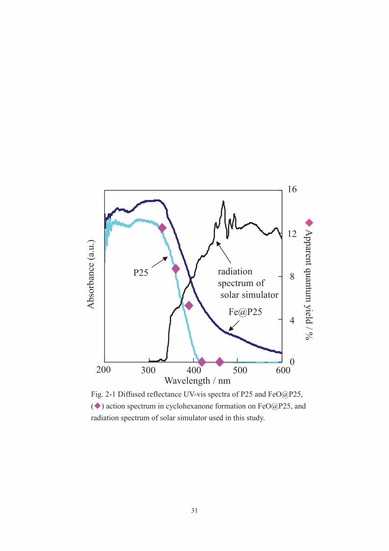
the P25 surface.[17, 18] The adsorption spectrum of FeO@P25 showed a shoulder
centered at 500 nm (Fig. 2-1). These results imply the presence of molecular-level iron
oxide adjacent to the P25 surface. An iron(III) acetylacetonate complex has been
reported to irreversibly react with surface titanol groups to form Ti–O–Fe covalent bond
via ligand exchange reaction. The amount of the immobilized iron oxide in FeO@P25
was estimated to be 0.81 Fe3+ ions nm−2. Taking the amount (more than 4 groups nm−2)
of titanol on P25 into account, iron oxide on P25 is thought to exist as patchy
molecular-level particles, rather than a contentious ultrathin layer.
31
Fig. 2-1 Diffused reflectance UV-vis spectra of P25 and FeO@P25, ( ) action spectrum in cyclohexanone formation on FeO@P25, and radiation spectrum of solar simulator used in this study.
Fe@P25
P25
200 300 400 500 600Wavelength / nm
Abs
orba
nce
(a.u
.)A
pparent quantum yield / %
0
4
8
12
16
radiation spectrum ofsolar simulator

32
2-3-2. Oxidation of cyclohexane and adsorption of cyclohexanone
Oxidation of cyclohexane
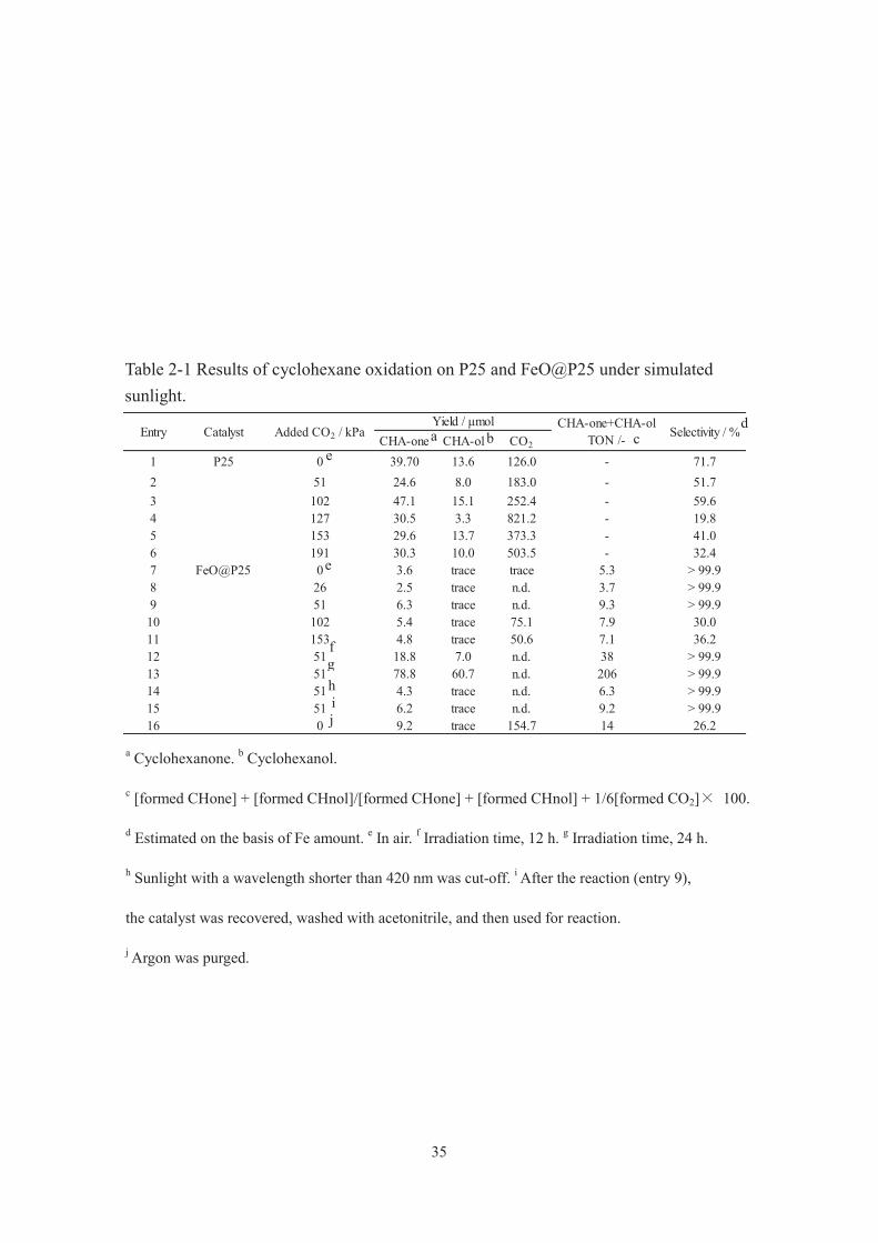
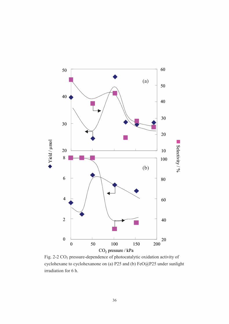
Table 2-1 summarizes all the results and Fig. 2-2 shows the CO2 pressure dependence
of the yield and the selectivity for cyclohexanone formation on P25 (entry 1 6) and
FeO@P25 (entry 7 16) under typical conditions. Cyclohexanone and cyclohexanol
describe as CHA-one and CHA-ol. When the reaction was done on Fe@P25 under 51
kPa of a CO2 atmosphere for 24 h, the best result, with a selectivity of ca. 100%, was
attained (Table 2-1, entry 13). A notable finding is that even the reaction on FeO@P25
in air gives a selectivity of ca. 100%, and by conducting the reaction under 51 kPa of
CO2, even when the irradiation time was prolonged, the yield is substantially improved
with a selectivity maintained at ca. 100% (Table 2-1, entries 7, 9, 12 and 13, and Fig.
2-2). To the best of our knowledge, 100% selectivity is the highest among those that had
been reported for photocatalytic cyclohexanone production under visible light.27,28 Also,
the yield (more than 200 TON) was considerably higher than those obtained in other
selective photocatalytic cyclohexane oxidations under visible light. For example, 68%
selectivity and 2.5 TON for cyclohexanone production were obtained on Cr–Si binary
oxide and 99% selectivity[29] and 22 TON for cyclohexanone and cyclohexanol
production were attained on hydrophobically modified Cr–Si binary oxide[28]. In the
present study, it is also worth mentioning that the photocatalytic performance of pristine
P25 is improved to give a higher yield with a selectivity maintained to some extent by
conducting the reaction under CO2 (Table 2-1, entries 1 and 3, and Fig. 2-2). All of the
results described above suggest that effective and selective sunlight-induced organic
synthesis is possible even on cheap and abundant photocatalysts just by conducting the
reaction under CO2 atmosphere.
33
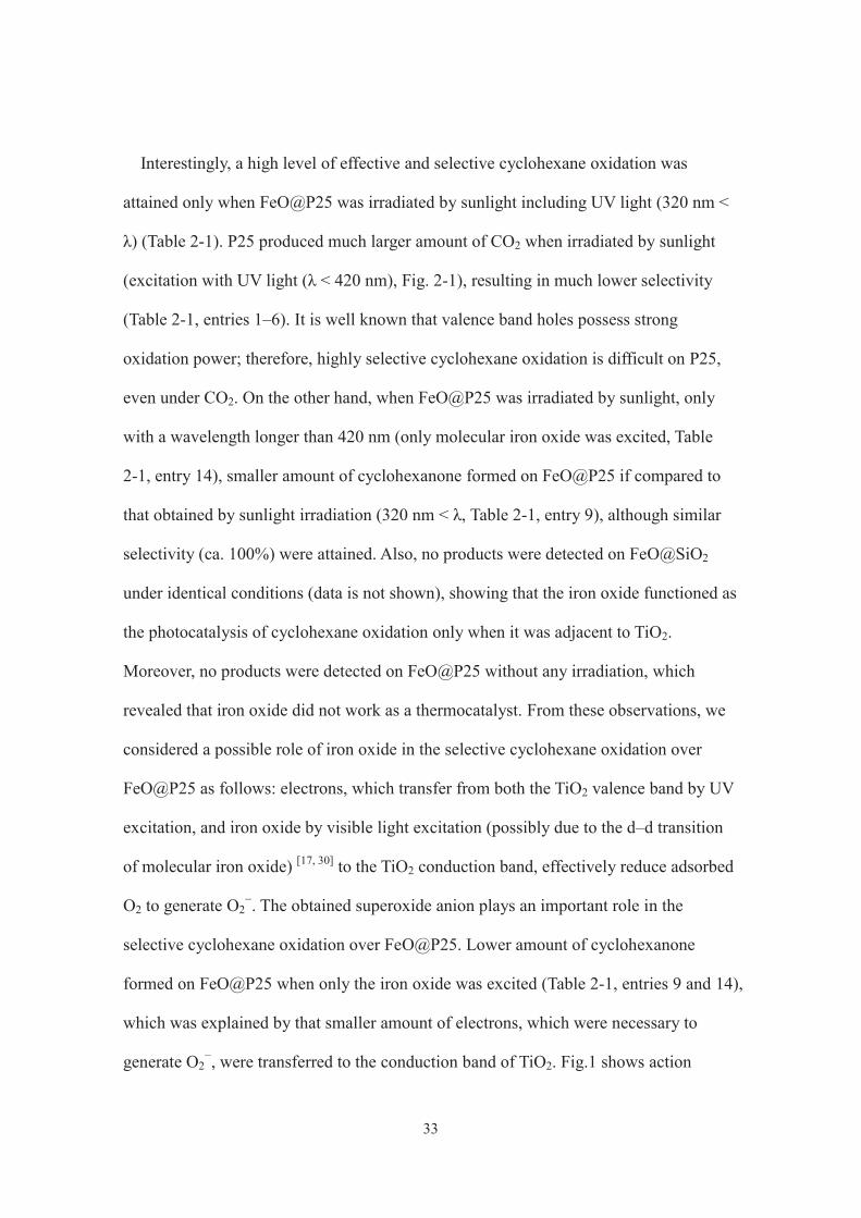
Interestingly, a high level of effective and selective cyclohexane oxidation was
attained only when FeO@P25 was irradiated by sunlight including UV light (320 nm <
λ) (Table 2-1). P25 produced much larger amount of CO2 when irradiated by sunlight
(excitation with UV light (λ < 420 nm), Fig. 2-1), resulting in much lower selectivity
(Table 2-1, entries 1–6). It is well known that valence band holes possess strong
oxidation power; therefore, highly selective cyclohexane oxidation is difficult on P25,
even under CO2. On the other hand, when FeO@P25 was irradiated by sunlight, only
with a wavelength longer than 420 nm (only molecular iron oxide was excited, Table
2-1, entry 14), smaller amount of cyclohexanone formed on FeO@P25 if compared to
that obtained by sunlight irradiation (320 nm < λ, Table 2-1, entry 9), although similar
selectivity (ca. 100%) were attained. Also, no products were detected on FeO@SiO2
under identical conditions (data is not shown), showing that the iron oxide functioned as
the photocatalysis of cyclohexane oxidation only when it was adjacent to TiO2.
Moreover, no products were detected on FeO@P25 without any irradiation, which
revealed that iron oxide did not work as a thermocatalyst. From these observations, we
considered a possible role of iron oxide in the selective cyclohexane oxidation over
FeO@P25 as follows: electrons, which transfer from both the TiO2 valence band by UV
excitation, and iron oxide by visible light excitation (possibly due to the d–d transition
of molecular iron oxide) [17, 30] to the TiO2 conduction band, effectively reduce adsorbed
O2 to generate O2−. The obtained superoxide anion plays an important role in the
selective cyclohexane oxidation over FeO@P25. Lower amount of cyclohexanone
formed on FeO@P25 when only the iron oxide was excited (Table 2-1, entries 9 and 14),
which was explained by that smaller amount of electrons, which were necessary to
generate O2−, were transferred to the conduction band of TiO2. Fig.1 shows action
34
spectrum on FeO@P25. The action spectrum (from 330 to 460 nm) in cyclohexanone
formation on FeO@P25 was in good agreementwith the UV-vis spectrum of P25 rather
than that of FeO@P25, supporting the above hypothesis. The mineralization of
cyclohexane and the successive oxidation of cyclohexanone and cyclohexanol hardly
occurred to give only trace amounts of CO2 on FeO@P25 (especially under lower
loading levels of CO2), since iron oxide efficiently prevented the interactions between
bulky molecules, cyclohexane and the partially oxidized products, with the valence
band holes on the P25 surface. The coating of TiO2 particles with silica and alumina
layers is useful to suppress the photocatalytic decomposition activity of organic
compounds[31, 32].
35
CHA-one CHA-ol CO2
1 P25 0 39.70 13.6 126.0 - 71.72 51 24.6 8.0 183.0 - 51.73 102 47.1 15.1 252.4 - 59.64 127 30.5 3.3 821.2 - 19.85 153 29.6 13.7 373.3 - 41.06 191 30.3 10.0 503.5 - 32.47 FeO@P25 0 3.6 trace trace 5.3 > 99.98 26 2.5 trace n.d. 3.7 > 99.99 51 6.3 trace n.d. 9.3 > 99.910 102 5.4 trace 75.1 7.9 30.011 153 4.8 trace 50.6 7.1 36.212 51 18.8 7.0 n.d. 38 > 99.913 51 78.8 60.7 n.d. 206 > 99.914 51 4.3 trace n.d. 6.3 > 99.915 51 6.2 trace n.d. 9.2 > 99.916 0 9.2 trace 154.7 14 26.2
CatalystEntry Added CO2 / kPaYield / μmol
Selectivity / %CHA-one+CHA-ol
TON /-
a Cyclohexanone. b Cyclohexanol.
c [formed CHone] + [formed CHnol]/[formed CHone] + [formed CHnol] + 1/6[formed CO2] 100.
d Estimated on the basis of Fe amount. e In air. f Irradiation time, 12 h. g Irradiation time, 24 h.
h Sunlight with a wavelength shorter than 420 nm was cut-off. i After the reaction (entry 9),
the catalyst was recovered, washed with acetonitrile, and then used for reaction.
j Argon was purged.
a b d
e
g h
j i
e
f
c
Table 2-1 Results of cyclohexane oxidation on P25 and FeO@P25 under simulated sunlight.
36
Selectivity
/ %Y
ield
/ μm
ol
CO2 pressure / kPa
20
30
40
50
10
20
30
40
0
2
4
6
8
20
80
40
100
60
0 50 150100 200
60
50
Selectivity/ %
Yie
ld/ μ
mol
CO2 pressure / kPa
20
30
40
50
10
20
30
40
0
2
4
6
8
20
80
40
100
60
0 50 150100 200
60
50
Fig. 2-2 CO2 pressure-dependence of photocatalytic oxidation activity of cyclohexane to cyclohexanone on (a) P25 and (b) FeO@P25 under sunlight irradiation for 6 h.
(a)
(b)
37
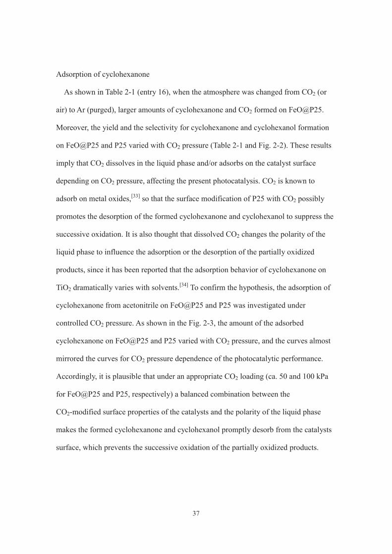
Adsorption of cyclohexanone
As shown in Table 2-1 (entry 16), when the atmosphere was changed from CO2 (or
air) to Ar (purged), larger amounts of cyclohexanone and CO2 formed on FeO@P25.
Moreover, the yield and the selectivity for cyclohexanone and cyclohexanol formation
on FeO@P25 and P25 varied with CO2 pressure (Table 2-1 and Fig. 2-2). These results
imply that CO2 dissolves in the liquid phase and/or adsorbs on the catalyst surface
depending on CO2 pressure, affecting the present photocatalysis. CO2 is known to
adsorb on metal oxides,[33] so that the surface modification of P25 with CO2 possibly
promotes the desorption of the formed cyclohexanone and cyclohexanol to suppress the
successive oxidation. It is also thought that dissolved CO2 changes the polarity of the
liquid phase to influence the adsorption or the desorption of the partially oxidized
products, since it has been reported that the adsorption behavior of cyclohexanone on
TiO2 dramatically varies with solvents.[34] To confirm the hypothesis, the adsorption of
cyclohexanone from acetonitrile on FeO@P25 and P25 was investigated under
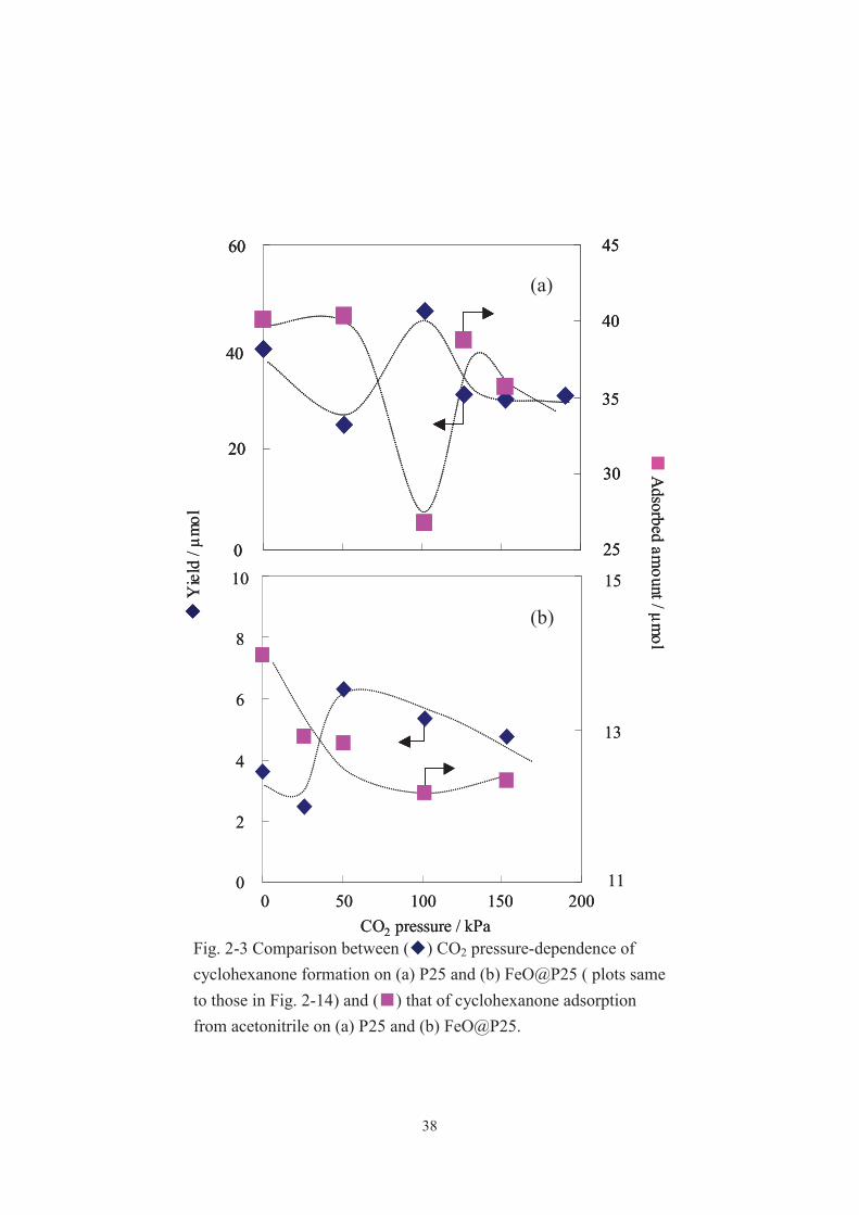
controlled CO2 pressure. As shown in the Fig. 2-3, the amount of the adsorbed
cyclohexanone on FeO@P25 and P25 varied with CO2 pressure, and the curves almost
mirrored the curves for CO2 pressure dependence of the photocatalytic performance.
Accordingly, it is plausible that under an appropriate CO2 loading (ca. 50 and 100 kPa
for FeO@P25 and P25, respectively) a balanced combination between the
CO2-modified surface properties of the catalysts and the polarity of the liquid phase
makes the formed cyclohexanone and cyclohexanol promptly desorb from the catalysts
surface, which prevents the successive oxidation of the partially oxidized products.
38
Adsorbed am
ount/ μmol
0 50 150100 2000
2
4
6
8
10
11
13
15
Yie
ld/ μ
mol
0
20
40
60
25
40
30
35
45
CO2 pressure / kPa
Adsorbed am
ount/ μmol
0 50 150100 2000
2
4
6
8
10
11
13
15
Yie
ld/ μ
mol
0
20
40
60
25
40
30
35
45
0
20
40
60
25
40
30
35
45
CO2 pressure / kPaFig. 2-3 Comparison between ( ) CO2 pressure-dependence of cyclohexanone formation on (a) P25 and (b) FeO@P25 ( plots same to those in Fig. 2-14) and ( ) that of cyclohexanone adsorption from acetonitrile on (a) P25 and (b) FeO@P25.
(b)
(a)

39
2-4. Conclusion
From all of above results, I found a highly effective and selective sunlight-induced
photocatalytic oxidation of cyclohexane, in acetonitrile, to cyclohexanone and
cyclohexanol on TiO2 (P25) modified with iron oxide under a CO2 atmosphere. [35] In
addition to the versatility, this idea is compelling in terms of CO2 reduction, capture and
storage. The present success opens up new opportunities to synthesize a wide variety of
fine chemicals in an economically and environmentally favorable fashion.
40
2-5. References
[1] A. Fujishima and K. Honda, Nature, 1972, 238, 37.
[2] M. Anpo and M. Takeuchi, J. Catal., 2003, 216, 505.
[3] R. Asahi, T. Morikawa, T. Ohwaki, K. Aoki and Y. Taga, Science, 2001, 293, 269.
[4] W.J. Youngblood, S.-H. A. Lee, K. Maeda and T. E. Mallouk, Acc. Chem. Res., 2009,
42, 1966.
[5] A. Primo, A. Cormaand H. Garcia, Phys. Chem. Chem. Phys., 2011, 13, 886.
[6] Y. Shiraishi, N. Saito and T. Hirai, J. Am. Chem. Soc., 2005, 127, 12820.
[7] T. W. Kim, S. G. Hur, S.-J. Hwang, H. Park, W. Choi and J.-H. Choy, Adv. Funct.
Mater., 2007, 17, 307.
[8] Y. Ide, M. Matsuoka and M. Ogawa, J. Am. Chem. Soc., 2010, 132, 16762.
[9] Y. Ide, Y. Nakasato and M. Ogawa, J. Am. Chem. Soc., 2010, 132, 3601.
[10] K. Maeda and D. Domen, J. Phys. Chem. Lett., 2010, 1, 2655.
[11] A. Kudo and T. Miseki, Chem. Soc. Rev., 2009, 38, 253.
[12] F. E. Osterloh, Chem. Mater., 2008, 20, 35.
[13] Y. Shiraishi and T. Hirai, J. Photochem. Photobiol., C, 2008, 9, 157.
[14] H. Kominami, A. Tanaka and K. Hashimoto, Chem. Commun., 2010, 46, 1287.
[15] Y. Tian and T. Tatsuma, Chem. Commun., 2004, 1810.
[16] K. Nagaveni, M. S. Hedge and G. Madras, J. Phys. Chem. B, 2004, 108, 20204.
[17] H. Tada, Q. Jin, H. Nishijima, H. Yamamoto, M. Fujishima, S. Okuoka, T. Hattori,
Y. Sumida and H. Kobayashi, Angew. Chem. Int. Ed., 2011, 50, 3501.
[18] Q. Jin, M. Fujishima and H. Tada, J. Phys. Chem. C, 2011, 115, 6478.
[19] Bart P. C. Hereijgers and Bert M. Weckhuysen, J. Catal., 2010, 270, 16.
[20] J. M. Herrmann and A. Sclafani, J. Phys. Chem., 1996, 100, 13655.
41
[21] A. R. Almeida, J. A. Moulijn and G. Mul, J. Phys. Chem. C., 2008, 112, 1552.
[22] D. Tsukamoto, A. Shiro, Y. Shiraishi and T. Hirai, J. Phys. Chem. C., 2011, 115,
19782.
[23] K. Sayama and H. Arakawa, J. Chem. Soc. Chem. Commun., 1992, 150.
[24] S. Naya, M. Teranishi, T. Isobe and H. Tada, Chem. Commun., 2010, 46, 815.
[25] Y. Ide, M. Matsuoka and M. Ogawa, J. Am. Chem. Soc., 2010, 132, 16762.
[26] Y. Ide, N. Nakamura, H. Hattori, R. Ogino, M. Ogawa, M. Sadakane and T. Sano,
Chem. Commun., 2011, 47, 11531.
[27] H. Sun, F. Blatter and H. Frei, J. Am. Chem. Soc., 1996, 118, 6873.
[28] Y. Shiraishi, H. Ohara and T. Hirai, New J. Chem., 2010, 34, 2841.
[29] Y. Shiraishi, Y. Teshima and T. Hirai, Chem. Commun., 2005, 4569.
[30] H. Yu, H. Irie, Y. Shimodaira, Y. Hosogi, Y. Kuroda, M. Miyauchi and K.
Hashimoto, J. Phys. Chem. C, 2010, 114, 16481.
[31] O. K. Park, Y. S. Kang and B. G. Jo, J. Ind. Eng. Chem., 2004, 10, 733.
[32] R. Kato, N. Shimura and M. Ogawa, Chem. Lett., 2008, 37, 76.
[33] J.Baltrusaitis, J. Schuttlefield, E. Zeitler and V. H. Grassian., Chem. Eng. J. 2011,
170, 471.
[34] C.B.Almquist and P. Biswas., Appl. Catal. A: General. 2001, 214, 259.
[35] Y. Ide, H. Hattori, M. Sadakane and T. Sano, Green Chem., 2012, 14, 1264.
42
Chapter 3
Extraordinary effects of argon atmosphere on TiO2 photocatalysis
3-1. Introduction
Recently, removal of toxic chemicals from wastewater is currently one of the most
compelling objectives in pollution control. Solar-driven photocatalysis has been
regarded to be a most effective and environmentally benign method for the purpose.
TiO2 is a promising photocatalyst due to its abundance, non-toxicity and high stability.
However, TiO2 responds only to the UV light, which takes only 3-4% of the incident
solar light, and the solar photocatalytic activity is insufficient for practical use.
Accordingly, as shown in Chapter 2, designing novel photocatalysts has been
extensively investigated in recent years. [1-5]
In this Chapter, when used under a unique environment, Ar atmosphere, even TiO2
exhibits a high solar photocatalytic activity toward the decomposition (mineralization)
of known organic contaminants in water.
43
3-2. Experimental
Reagents and materials
P25 and rutile (JRC-TIO-06) were supplied by Nippon Aerosil and Catalysis Society
of Japan, respectively. Anatase, NaOH and Ba(OH)2was purchased from Wako Pure
Chemical Industries, Ltd. Cationic organic dyes, crystal violet (CV) and basic violet 4
(BV), were purchased from Tokyo Chemical Industry Co., Ltd. All reagents and
materials were used as received.
Photocatalytic test
A mixture of TiO2 (60 mg) and a solution of CV or BV in water (25 mL, 50 or 250
ppm) in a stainless-made closed container (75 mL) equipped with Pyrex glass and gas
inlet/outlet, was irradiated ( > 320 nm) by a solar simulator (XES-155S1 San-Ei
Electric Co., Ltd., 500 W Xe lamp,1000 W m-2) at room temperature, under shaking.
Gas flow rate was 0.1 mL min-1. Prior to photoirradiation, the mixture was settled in
dark for 15 min under each atmosphere. For the reaction at a higher pH, 0.1 M-NaOH
aqueous solution was added into the starting mixture to adjust the pH to 9. After the
reaction, the supernatant was separated by filtration and analyzed by UV-vis
spectroscopy (V-570, JASCO Co.) to determine the amount of residual organic dye in
the supernatant. The gas phase CO2 was quantitatively analyzed by GC-TCD (GC-8A,
the measurement accuracy was within 1.0%) before and after photocatalytic test. When
the reaction was conducted under gas flow environments, a saturated Ba(OH)2 solution
was set up at the down stream of the flow to capture CO2 formed as BaCO3 and then the
amount of Ba in the supernatant was determined with Inductively Coupled Plasma
Atomic Emission Spectroscopy (ICP-AES, SPS7700, Seiko Instruments Inc.). The
44
photocatalysis under an Ar or a N2 atmosphere (150 kPa) was also conducted by the
way similar to that conducted for the photocatalysis in other environments.
Adsorption of CV
Adsorption test was conducted by the way similar to that conducted for the
photocatalysis except that the mixture of P25 and aqueous CV was shaken in dark under
each atmosphere immediately after mixing. After the adsorption, the supernatant was
separated by filtration and analyzed by UV-vis spectroscopy to determine the amount of
residual organic dye in the supernatant.
Gas adsorption
The adsorption desorption isotherms of O2, N2 or Ar on P25 were measured at 77 K
with a BEL-Max (BEL Japan, Inc.). Prior to the measurements, P25 was evacuated at
353 K for 3 h.
Estimation of amounts of carbon deposits
The recovered P25 was washed sufficiently with water and ethanol to remove
possibly adsorbed CV and analyzed by thermogravimetric-differential thermal analysis
under air using a SSC/5200 (Seiko Instrument Inc.)
Contact angle measurement
Deionized water was bubbled with CO2, N2, O2 or Ar gas for 15 min. Each droplet
was positioned on a fluorocarbon polymer (PTFE) substrate and the contact angle
values were measured in an ambient environment, at room temperature.
45
3-3. Results and discussion
Crystal violet (named as CV), whose molecular structure is shown in Fig. 3-1 a, is a
cationic organic dye in wastewater coming from dyeing and finishing industry and
known to be relatively stable under solar light. I also confirmed that no appreciable
decomposition of CV was detected in the absence of catalyst under the present
irradiation condition. Fig. 3-2 (a: CV decomposition, b: CO2 evaluation) shows the
time-course curves of photocatalytic reactions on TiO2 (P25) in aqueous solutions of CV
under simulated solar light irradiation in different atmospheres. In air (the reaction
container was closed), CV was photocatalytically decomposed gradually, forming the
completely oxidized products, CO2 (black circles). [6-9] Surprisingly, when the
photocatalytic reaction was conducted under Ar flow (the gas phase of the container was
ventilated with pure Ar gas), CV decomposition and CO2 evolution occurred much more
rapidly (purple squares). The initial rate for photocatalytic CV decomposition under Ar
flow was 2.7 μmol min-1, which was about 12-times faster than that (0.22 μmol min-1)
observed in air. Almost all CV mineralized into CO2 under Ar flow at the end of the
irradiation; while, the degree of the mineralization was only about 50 % in air (complete
mineralization of 1 mol of CV implies the evolution of the equivalent amount, 25 mol,
of CO2 as shown in Fig. 3-1 a). Just by using an inert and versatile Ar gas, namely, in an
environmentally and economically benign fashion, the solar photocatalytic activity of
P25 was substantially improved. It should be noted here that air flow (green squares)
and N2 flow (data not shown) were less effective in the photocatalytic reaction than Ar
flow, showing an important role of Ar, not but N2 and O2, in the photocatalysis.
Most TiO2 photocatalytic reactions for organic pollutants removal requires
(dissolved) O2 as both a conduction band electron scavenger and a reagent for
46
mineralization; on the other hand, some photocatalytic reactions can be enhanced in the
absence of O2 when the reductive pathways are dominant. The present photocatalytic
reaction under Ar flow is not the former cases, because CV decomposition rate in the
absence of dissolved O2 was slower than that in the presence of dissolved O2 and CO2
evolution was observed even without dissolved O2 (Fig. 3-2 a and b, red triangles).
Indeed, many organic dyes, like CV, are thought to be photocatalytically degraded and
mineralized mainly with oxidizing species such as hydroxy radicals and superoxide
radicals from water and dissolved O2, respectively. [6-9] I measured the amount of
dissolved O2 in an aqueous CV solution after 15 min-Ar flow to be 5.01 mg L-1, which
was comparable to that (8.59 mg L-1) in the original solution. Dissolved O2 was thus not
effectively removed from the reaction mixture during the present photocatalysis under
Ar flow. Therefore, even under Ar flow, dissolved O2 successfully acted as a conduction
band electron scavenger and/or a reagent for CV mineralization. When the Ar flow rate
was slowed down to half (0.05 mL min-1) and accelerated twofold (0.2 mL min-1), the
amounts of dissolved O2 in an aqueous CV solution after 15 min of the flows were 5.82
and 4.91 mg L-1, respectively. The photocatalytic CV decomposition rate did not depend
on the Ar flow rate (Fig. 3-2c). Therefore, a higher flow rate of Ar negatively affected
the photocatalysis because a larger amount of O2 was removed.
The usefulness of Ar flow was further confirmed by the photocatalytic reaction at a
higher concentration of initial CV. As described above, dissolved O2 is required for
effective photocatalytic CV mineralization over P25. Therefore, at a higher
concentration of initial CV, the amount of O2 dissolved in water could strongly affect
the activity for CV decomposition, namely, O2 flow could accelerate photocatalytic CV
decomposition more effectively than Ar flow did. However, as can be seen in Fig. 3-2 d,
47
even at a much higher initial CV concentration, photocatalytic CV decomposition was
considerably accelerated under Ar flow. On the other hand, O2 flow substantially
suppressed CV decomposition activity.
I investigated other photocatalytic oxidations under Ar flow to show the versatility of
the strategy. As shown in Fig. 3-3, both the photocatalytic decomposition of another
known cationic dye in wastewater, basic violet 4 (BV, Fig. 3-1 b) over P25 and that over
anatase-phase-TiO2 (while P25 is composed mainly of anatase and rutile
crystallites[10,11]) were also considerably accelerated when the reactions were conducted
under Ar flow. On the other hand, with rutile-phase-TiO2, that showed no appreciable
photocatalytic activity toward the decomposition of neither CV nor BV under the
identical irradiation condition, the activity was not improved at all even under Ar flow
(CO2 hardly evolved). It should be noted here that Ar flow improved the adsorption
ability of rutile for CV (Fig. 3-3c).
Although a number of factors should concern the highly improved photocatalytic
decomposition of CV and BV under Ar flow, in this study, I propose three possible
factors. The first of which is the pH of aqueous mixture. It is generally known that a
larger amount of cationic species adsorb on TiO2 surface in dark (without light
irradiation) when the pH of aqueous mixtures is higher, because increasing the pH
causes the de-protonation of neutral hydroxyl groups on TiO2 surface into negatively
charged ones.[12] Accordingly, the initial rate of photocatalytic reactions of cationic
reactants on TiO2 increases with increasing the pH of reaction mixtures.[13] Here I
compared the adsorption of CV from water on P25 under Ar flow (Fig. 3-4 a, purple
squares) to that under air flow (green squares). A larger amount of CV adsorbed on TiO2
under Ar flow, which was explained by higher pH of the aqueous mixture all during the
48
adsorption (Fig. 3-4 b). Difference in pH variation between the two aqueous mixtures
was explained as follows. The pH of water decreases depending on the amount of
dissolved CO2, which is proportional to the concentration of CO2 in gas phase according
to Henry’s law. Under air flow, the pH of aqueous CV mixture decreased by
continuously supplied CO2 in the gas phase and hardly increased afterward (Fig. 3-4 b,
green squares). On the other hand, under Ar flow, CO2 in the gas phase was removed
with Ar and thus CO2 evolved from aqueous CV mixture to be removed, which
increased the pH gradually (Fig. 3-4 b, purple squares). Therefore, during the present
photocatalytic reaction under Ar flow, CO2 derived from CV mineralization was
effectively removed from the reaction mixture to maintain the pH higher, which
promoted CV adsorption and decomposition. In the case of the photocatalysis in air,
CO2 gas generated by CV decomposition remained in the closed reaction container. The
estimated concentration of CO2 was up to 3% (at 240 min-irradiation in Fig. 3-2 b) if
the free space volume is the same as that of the solution and if all CO2 go into the free
space (gas phase).[14] This concentration is higher than that in air flow (ca. 0.04%).
Accordingly, photocatalytic CV decomposition rate in air was slower than that under air
flow and considerably slower than that under Ar flow. The solubility of Ar in water
(3.37 cm3/100 g, 20 ºC 1 atm) is higher than those of N2 (1.56 cm3/100 g) and O2
(3.10 cm3/100 g), which might also contribute to remove CO2 from aqueous CV mixture
more effectively under Ar flow.
To confirm the speculation described above, photocatalytic CV decomposition on P25
under CO2 flow and CV adsorption on P25 from CO2-saturated water in air, namely,
under much lower pH than that of aqueous CV mixture under air flow, were
investigated. As expected, photocatalytic CV decomposition under CO2 flow was
49
suppressed if compared to that in air (Fig. 3-2a, gray circles). CV adsorption was also
suppressed under such low pH and promoted immediately after applying Ar flow,
namely, increasing pH (Fig. 3-4, gray circles). As described above (Fig. 3-3c), the
amount of the adsorbed CV from the aqueous mixture on the photocatalytically inactive
rutile during irradiation under Ar flow was larger than that in air, which was also due
to the increase of the solution pH.
Judging from the above discussion, photocatalytic oxidations of CV or BV over TiO2
in “buffered” water seems better choice for simple improvement of the activity since the
pH control by adding some bases is very easy as compared to Ar flow. I conducted
photocatalytic CV decomposition over P25 at an initial pH of 9 (the final one of 8)
adjusted by an aqueous NaOH solution, revealing that the initial CV decomposition rate
and the degree of CV mineralization were much lower than those observed under Ar
flow (Fig. 3-2 a, black open circles vs purple squares). This result indicates again a
merit of Ar flow to improve the activity of TiO2 photocatalysis.
As the second possible factor for the improved TiO2 photocatalysis depending on
atmosphere gases, I considered the effects of gas adsorption on TiO2 surface on the
photocatalytic activity. Fig. 3-5 depicts the adsorption/desorption isotherms of N2, O2,
or Ar on P25 at 77 K (at 298 K, all the gases hardly adsorbed). It was revealed that Ar
adsorbed on P25 less effectively than did N2 and O2. Therefore, gases other than Ar
might adsorb on TiO2 to prevent organic dyes adsorption and decomposition. I cannot
rule out the possibility that the adsorption behaviour of each gas on P25 from the gas
phase is different from that from the aqueous solution.
50
Finally, I considered the possible deactivation of TiO2 during the present reactions
depending on atmospheres. It is well-known that the accumulation of carbon deposits on
TiO2 during the photocatalytic oxidation of organic compounds deactivates the
photocatalytic activity.[15] Here I recovered TiO2 after photocatalytic CV decomposition
under different atmospheres at similar CV consumption (15, 120 and 240 min for Ar
flow, air flow and air environments, respectively, in Fig. 3-2 a) and estimated the
amounts of carbon deposits in these samples, giving the following sequence; in air (1.1
mass%) > under air flow (0.6 mass%) > under Ar flow (0.3 mass%) as shown in Fig.
3-6. This sequence was opposite to that of photocatalytic CV decomposition and CO2
evolution rates. Therefore, the oxidized products of CV were removed (desorbed) more
effectively from TiO2 surface under Ar flow, which inhibited the accumulation of
carbon deposits and thus preserved the original activity during the photocatalysis.
As to a possible reason for the improved desorption of the oxidized products of CV
from TiO2 under Ar flow, I consider that the nature of the reaction media plays an
important role, because some literature have discussed the effects of natures, such as
polarity and hydrophilicity/hydrophobicity, of reaction media for photocatalysts on the
desorption of oxidized products and the photocatalytic activity.[16 20] As can be seen in
Fig. 3-7, the hydrophilicity sequence of water saturated with CO2, N2, O2 or Ar gas
estimated as follows from the wettability on a fluorocarbon polymer (PTFE) substrate;
CO2 > O2 > Ar > N2. The change of UV-vis absorption spectra of CV during the
photocatalysis over P25 in different environments showed that when CV consumption
was low, e.g. in air or under O2 flow, a new absorption band appeared at around 265 nm
(Fig. 3-8), suggesting that the photocatalytic mechanism for CV degradation and
decomposition under Ar flow is different to those in other environments (in such

51
environments, larger amounts of intermediates which convert into carbon deposits are
thought to be generated). Thus, aqueous CV mixture flowed with Ar, which has a
well-balanced hydrophilic/hydrophobic nature, might be more compatible with the
oxidized products of CV (or BV) having hydrophilic and hydrophobic functional groups,
such as N-de-methylated intermediates and cleavage intermediates,[6, 7] than those
flowed with the other gases.
As described above, photocatalytic CV decomposition over P25 did not depend on
the Ar flow rate (Fig. 3-2 c), which suggests the importance of a balance of CO2
removal and Ar dissolution. Also, pH control by NaOH was not effective to improve
P25 photocatalysis (Fig. 3-2 a). Furthermore, when photocatalytic CV decomposition
over P25 was conducted under an Ar atmosphere (150 kPa), but not Ar flow, the initial
rate was slightly higher than that obtained in air (Fig. 3-9, purple pluses); on the other
hand, a N2 atmosphere (150 kPa) substantially lowered the activity (yellow pluses).
These results strongly support our hypothesis that Ar acts not only to remove CO2 (to
control solution pH) but also to tune the hydrophilicity/hydrophobicity of solution and
then to desorb the intermediate products of CV that convert into carbon deposits.
From all the results obtained, the present methodology, TiO2 solar photocatalysis
under Ar flow, seems be applicable to other photocatalytic reactions involving the
adsorption of cationic reactants and the evolution of CO2, such as the photocatalytic
removal (recovery) of metals from water containing metal ions and hydrogen
production from water which are often conducted in the presence of sacrificial reagents
(e.g. alcohols, organic acids).
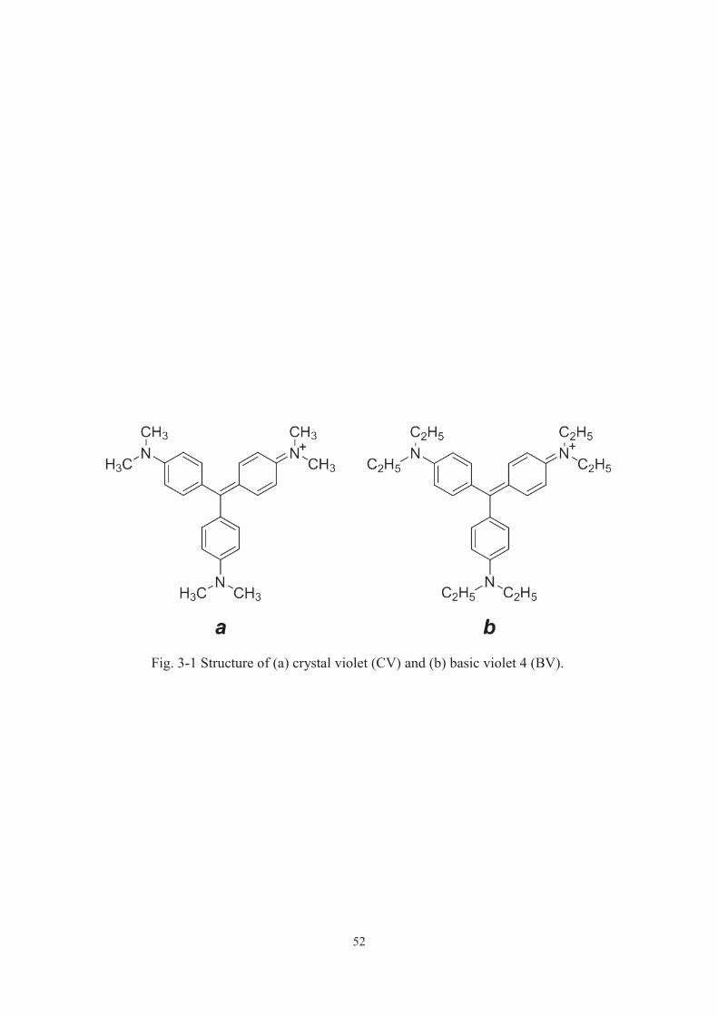
52
Fig. 3-1 Structure of (a) crystal violet (CV) and (b) basic violet 4 (BV).

53
Fig. 3-2 a and b, time-course curves of photocatalytic decomposition of CV over
P25 under various conditions ( ) in air, ( ) under air flow, ( ) Ar flow, ( )
in air without dissolved O2, ( ) CO2 flow, ( ) in air at a higher pH and ( ) O2
flow. (c) Time-course curves of CV decomposition over P25 under 0.05 ( ), 0.1
( ) and ( ) 0.2 mL min-1 of Ar flow. d, time-course curves of photocatalytic
decomposition of CV at a higher CVconcentration over P25 under various
conditions ( ) in air, ( ) O2 flow and ( ) Ar flow.

54
Fig. 3-3 Time course curves of BV decomposition over (a) P25 and (b) anatase
in air ( ) and under Ar flow ( ). (c) Time-course curves of CV decomposition
over rutile in air ( ) and under Ar flow ( ).
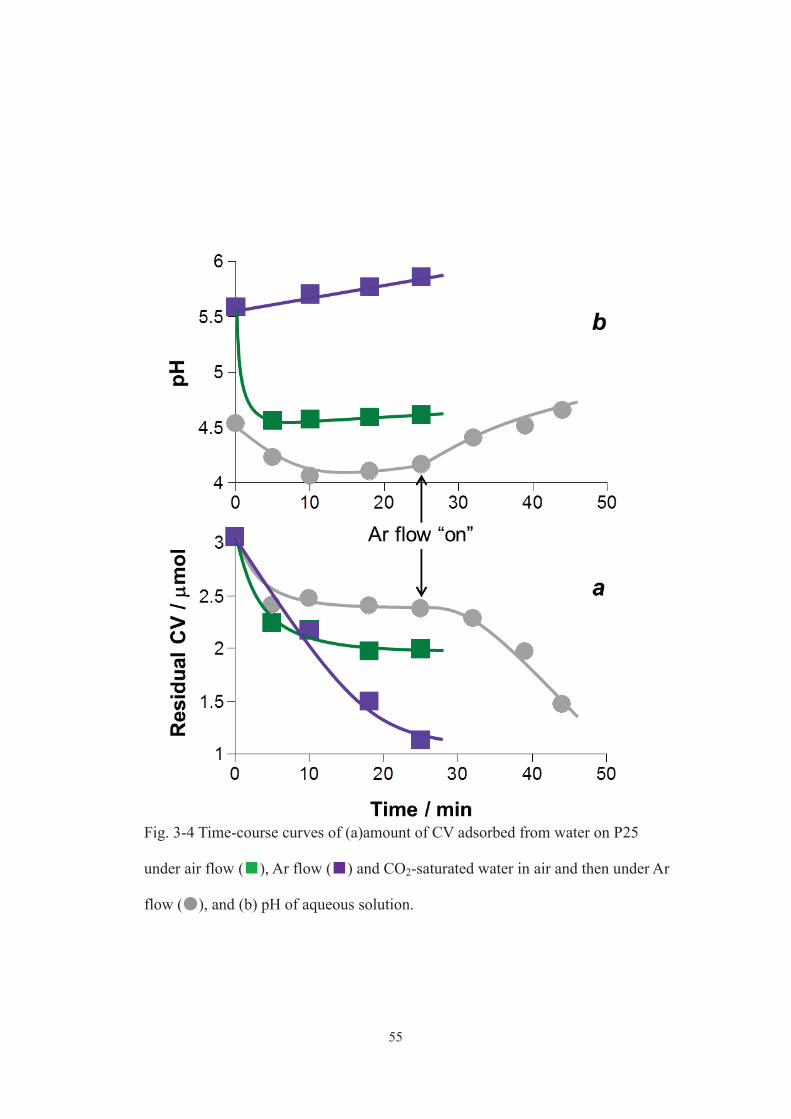
55
Fig. 3-4 Time-course curves of (a)amount of CV adsorbed from water on P25
under air flow ( ), Ar flow ( ) and CO2-saturated water in air and then under Ar
flow ( ), and (b) pH of aqueous solution.
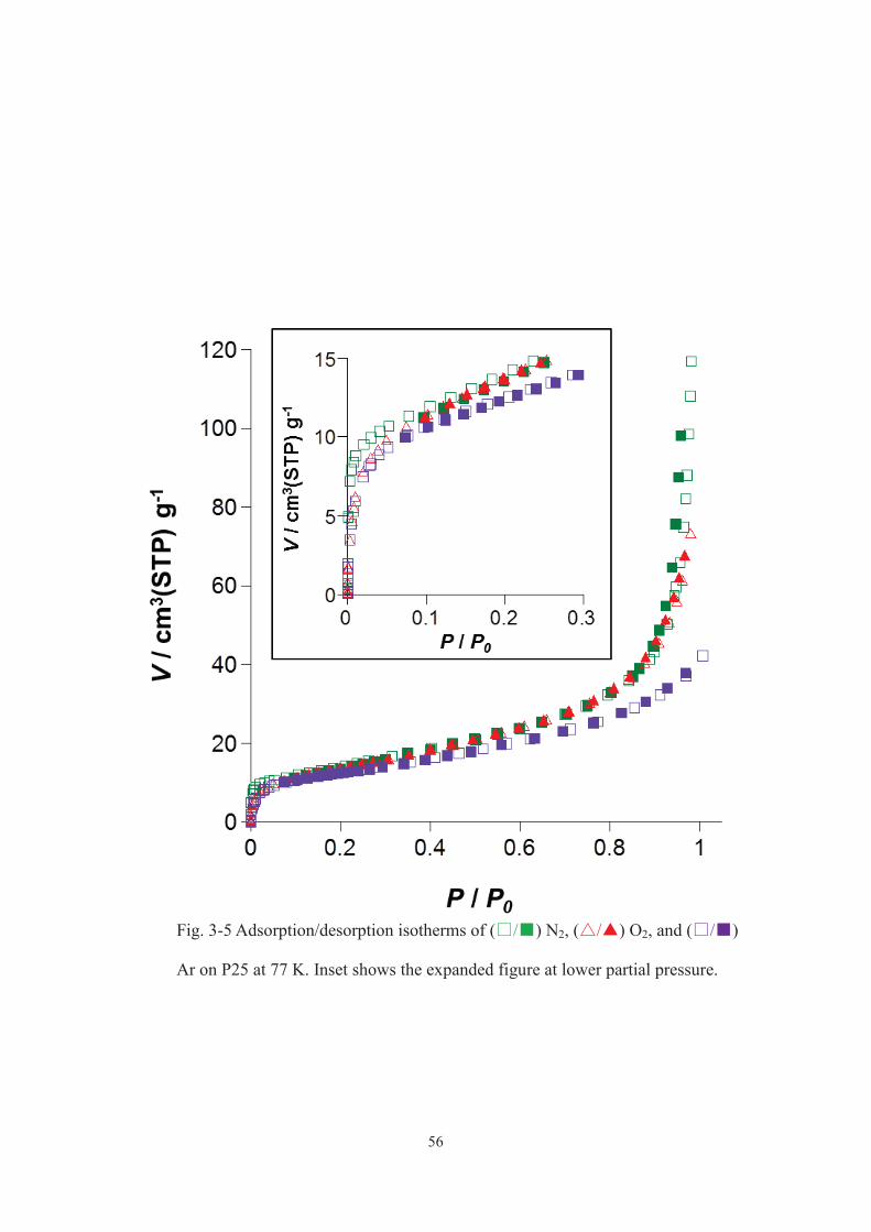
56
Fig. 3-5 Adsorption/desorption isotherms of ( / ) N2, ( / ) O2, and ( / )
Ar on P25 at 77 K. Inset shows the expanded figure at lower partial pressure.
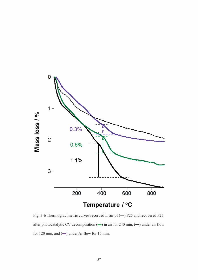
57
Fig. 3-6 Thermogravimetric curves recorded in air of (―) P25 and recovered P25
after photocatalytic CV decomposition (▬) in air for 240 min, (▬) under air flow
for 120 min, and (▬) under Ar flow for 15 min.
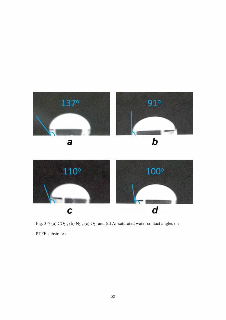
58
Fig. 3-7 (a) CO2-, (b) N2-, (c) O2- and (d) Ar-saturated water contact angles on
PTFE substrates.
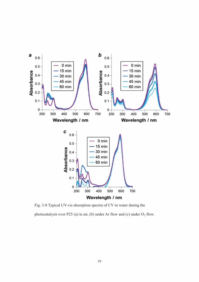
59
Fig. 3-8 Typical UV-vis absorption spectra of CV in water during the
photocatalysis over P25 (a) in air, (b) under Ar flow and (c) under O2 flow.
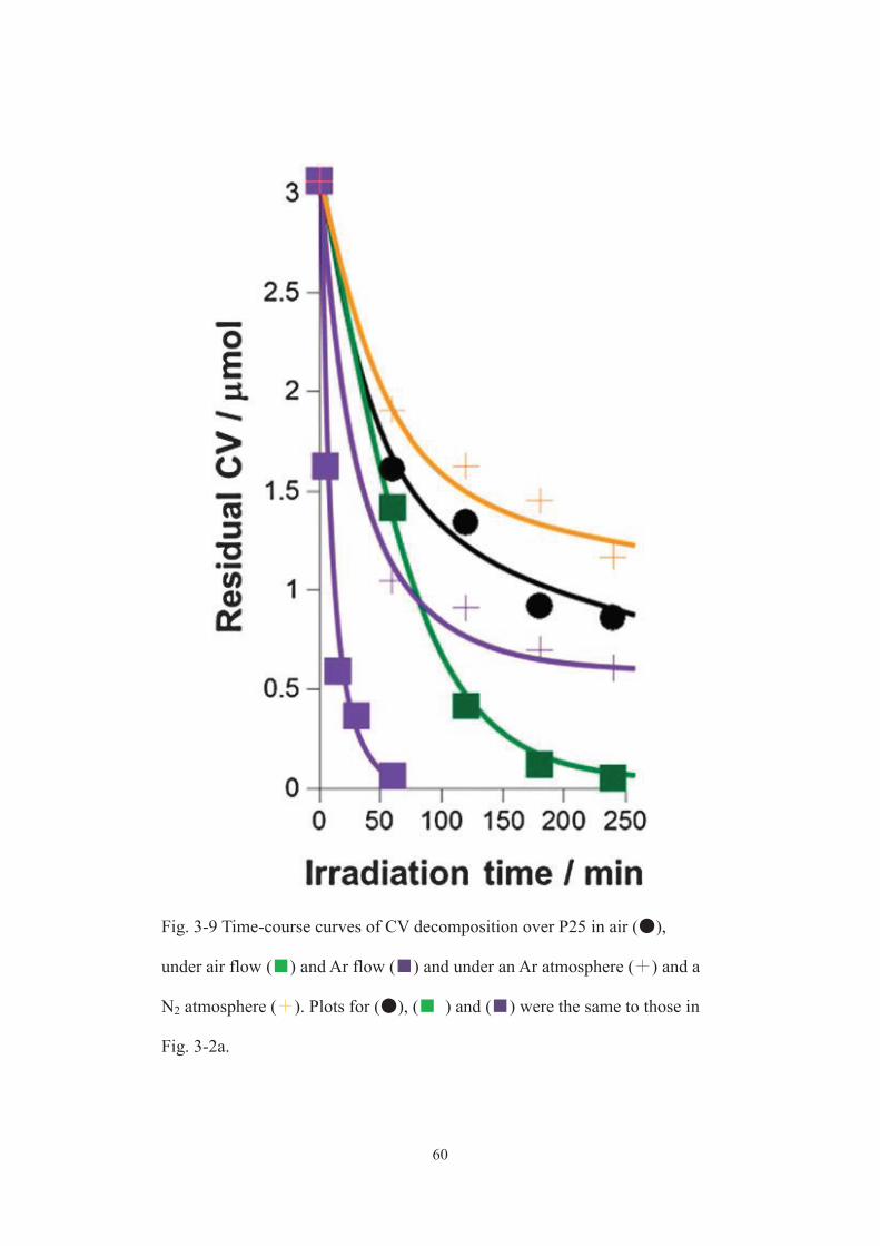
60
Fig. 3-9 Time-course curves of CV decomposition over P25 in air ( ),
under air flow ( ) and Ar flow ( ) and under an Ar atmosphere ( ) and a
N2 atmosphere ( ). Plots for ( ), ( ) and ( ) were the same to those in
Fig. 3-2a.

61
3-4. Conclusion
I have reported a conceptually new methodology to substantially improve the
photocatalytic activity of TiO2 under solar light irradiation, which is achieved by
conducting the reaction under an Ar atmosphere. [21] Ar, a noble gas, is widely used as
inert gas in industry but still scientifically investigated in a number of disciplines. I
anticipate that many known photocatalytic processes are investigated under an Ar
atmosphere to improve their photocatalytic activities and fully understand the reaction
mechanisms.
62
3-5. References
[1] M. A. Fox and M. Dulay, Chem. Rev., 1993, 93, 341.
[2] R. Asahi, T. Morikawa, T. Ohwaki, K. Aoki and Y. Taga, Science, 2001, 293, 269.
[3] M. Anpo and M. Takeuchi, J. Catal., 2003, 216, 505.
[4] A. Fujishima, X. Zhang and D. A. Tryk, Surf. Sci. Rep., 2008, 63, 515.
[5] H. Tada, T. Kiyonaga and S. Naya, Chem. Soc. Rev., 2009, 38, 1849.
[6] N. Teshima, S. Yamamoto, Q. Zhang, Z. Yamada and T. Sasaki, Bunseki Kagaku,
2007, 56, 99.
[7] W.-L. Lee, S.-T. Huang, J.-L. Chang, J.-Y. Chen, M.-C. Cheng and C.-C. Chen, J.
Mol. Catal. A: Chem., 2012, 361, 80.
[8] A. B. Prevot, C. Baiocchi, M. C. Brussino, E. Pramaurp, P. Savarino, V. Augugliaro,
G. Marci and L. Palmisano, Environ. Sci. Technol., 2001, 35, 971.
[9] C. Chen and C. Lu, J. Phys. Chem. C, 2007, 111, 13922.
[10] B. Ohtani, O. O. Prieto-Mahaney, D. Li and R. Abe, J. Photochem. Photobiol. A,
2010, 216, 179.
[11] T. Ohno, K. Sarukawa, K. Tokieda and M. Matsumura, J. Catal., 2001, 203, 82.
[12] P. W. Schindler and H. Gamesjager, Colloid Polym. Sci., 1972, 250, 759.
[13] B. Ohtani, Y. Okugawa, S. Nishimoto nad T. Kagiya, J. Phys. Chem., 1987, 91,
3550.
[14] N. Iyi and H. Yamada, Chem. Lett., 2010, 39, 591.
[15] H. Einaga, S. Futamura and T. Ibusuki, Phys. Chem. Chem. Phys., 1999, 1, 4903.
[16] P. Boarini, V. Carassiti, A. Maldotti and R. Amadelli, Langumuir, 1998, 14, 2080.
[17] Y. Ide, M. Matsuoka and M. Ogawa, ChemCatChem, 2012, 4, 628.

63
[18] Y. Ide, N. Nakamura, H. Hattori, R. Ogino, M. Ogawa, M. Sadakane and T. Sano,
Chem. Commun., 2011, 47, 11531.
[19] Y. Ide, H. Hattori, S. Ogo, M. Sadakane and T. Sano, Green Chem., 2012, 14,
1264.
[20] Y. Ide, R. Ogino, M. Sadakane and T. Sano, ChemCatChem, 2013, 5, 766.
[21] Y. Ide, H. Hattori and T. Sano, Phys. Chem. Chem. Phys., 2014, 16, 7913.
64
Chapter 4
Ternary modified TiO2 as simple and efficient photocatalyst for green organic synthesis
4-1. Introduction
As described in chapter 2, designing novel photocatalysts for effective and selective
synthesis of fine chemicals has been extensively investigated in recent years.[1-5] The
co-doping with two kinds of heteroelements [6] and the co-modification with two kinds
of nanoparticles [7] or organic dyes [8] of a semiconductor photocatalyst can provide
better photocatalytic performance of the catalyst as a result of the improved charge
separation efficiency and the broadening of light absorption spectra, and so on. The
modification (grafting) of TiO2 with Fe3+ or Ni2+ has been known to improve the
UV-induced activity and impart the visible light response. [9, 10] Au nanoparticle
modification (loading) has also been known to cause the same effects on TiO2. [11-13] On
the other hand, Au nanoparticle modification on TiO2 has been reported to drastically
decrease the amount of the surface titanol, [14] which promotes the desorption of
partially oxidized products from the catalyst surface, thus preventing the successive
oxidation. [15] These reports motivate me to design TiO2-based photocatalysts by the
appropriate surface modification.
In chapter 2, I found that partial oxidation of cyclohexane, which is industrially very
important reaction, selectively proceeds under simulated sunlight irradiation when using
TiO2 modified with Fe [16]. Although the selectivity was almost 100%, however, the
yield is low and further improvement of the catalytic activity for practical application is
necessary. In this chapter, I report, for the first time, the usefulness of the ternary
modification of TiO2 for substantially improving the photocatalytic organic synthesis

65
activity, which is revealed by the fact that TiO2 ternary-modified with Fe3+, Ni2+, and Au
nanoparticles shows an unprecedentedly high photocatalytic efficiency for selective
cyclohexane oxidation under sunlight irradiation.
66
4-2. Experimental
Reagents and materials
P25 was supplied by Nippon Aerosil. Gold (III) chloride trihydrate (HAuCl4 3H2O)
was purchased from SIGMA-ALDRICH. Fe(III)acetylacetonate (Fe(acac)3), Ni(II)
acetylacetonate (Ni(acac)2), ethanol, hexane, naphthalene and NaOH were purchased
from Wako Pure Chemical Industries, Ltd. Cyclohexane (named as CHA) and
acetonitrile were purchased from Nacalai tesque Ltd. All reagents and materials were
used as received.
Synthesis of ternary-modified TiO2 with Fe3+, Ni2+, and Au nanoparticles (named as
Fe/Ni/Au@P25)
Fe@P25 or Ni@P25 was prepared according to the literature: [18, 10] 1.0 g of P25 was
added to 6.5 x 10⁻⁴ mol L-1 of iron(III) acetylacetonate (or nickel(II) acetylacetonate) in
a mixed solvent (100 mL, ethanol/hexane = 3:17 v/v) and the mixture was stirred at
room temperature for 24 h. The product was separated by centrifugation (3000 rpm, 20
min), washed repeatedly with the same solvent, and calcined at 500 ºC for 1 h.
Fe/Ni@P25 was prepared by reacting 1.0 g of Ni@P25 with 6.5 x 10⁻⁴ mol L-1 of the
iron complex in the mixed solvent followed by washing and calcination. Au@P25 was
prepared by a deposition-precipitation method. P25 was added to an aqueous solution of
HAuCl4 3H2O (400 mL, Au/TiO2 ratio is 2 wt%) in which pH was adjusted to be 10 by
0.2 mol L-1 of an aqueous NaOH solution, and the mixture was ultrasonicated for 1 h
and then stirred at 70 ºC for 2 h. The product was separated by ultracentrifugation
(18000 rpm, 20 min), washed with water, and dried at 100 ºC overnight. Finally, the
powder was calcined at 500 ºC in air for 4 h. Fe/Ni/Au@ P25 was synthesized by
67
modifying Au@P25 (1.0 g) with Ni and Fe sequentially using the nickel and iron
complexes (6.5 x 10⁻⁴ mol L-1 for each compound), respectively.
Oxidation of cyclohexane
Photocatalytic conversions were carried out by photo-irradiation with solar simulator
(San-Ei Electric Co., Ltd.) to a mixture of catalyst (30 mg) and O2-saturated acetonitrile
(18 mL) solution of cyclohexane (2 mL) in a stainless-made closed container equipped
with Pyrex glass (75 mL) at 42 ºC, under shaking. The container was placed by ca. 30
cm away from the light source to irradiate 1 solar (1000 w m-2)-power light to the
mixture. For action spectra measurement, the full arc from a 500 W-Xe lamp (Ushio)
was monochromated using SM-25 (Bunkoukeiki) and then irradiated to the mixture.
Spectra and light intensity of monochromated Xe lamp were determined using a
spectroradiometer USR-45D (Ushio). CO2 and organic compounds were quantitatively
analyzed by GC. Naphthalene was used as internal standard.
Measurement of action spectrum
For action spectra measurement, the full arc from a 500W-Xe lamp (Ushio) was
monochromated using SM-25 (Bunkokeiki) and then irradiated mixture of catalyst (60
mg), O2-saturated acetonitrile (18 mL) solution of cyclohexane (2 mL) in a
stainless-made closed container equipped with Pyrex glass (75 mL). After analyzing gas
phase, the irradiation was started for 24 h. Organic compounds recovered by filtration,
and the resulting supernatant was analyzed by GC-FID (Shimazu GC-2014).
Naphthalene was used as internal standard for GC-FID.
68
Adsorption of CHA on photocatalyst
Adsorption test were similar way that conducted in photocatalytic conversions exept
that catalyst and an acetonitrile solution (20mL) containing CHA (1mL) and CHA-one
(0.001-0.01 mL), which was not bubbled with O2, were shaken in dark. Naphthalene
was used as internal standard for GC-FID.
Analysis equipment and evaluation condition
Apparatus using for characterization of synthesis catalysts and quantification of
substrate and products of photocatalytic test were shown below. Diffused reflectance
UV-vis spectra measured with ultraviolet-visible near-infrared spectrophotometer
(Nihonbunko, JASCO V-570). Measurement wavelength range were 200 - 800 nm, and
BaSO4 used for baseline. The successful surface modification of TiO2 was confirmed by
the X-ray Photoelectron Spectroscopy (XPS, Shimadzu, Kratos ESCA-3400). Coupled
Plasma Atomic Emission Spectroscopy (ICP-AES, Seiko Instruments Inc., SPS7700)
was used for confirming the amounts of the grafted Fe3+ and Ni2+. Transmission electron
microscopic (TEM) images were obtained with a JEOL JEM-2011.
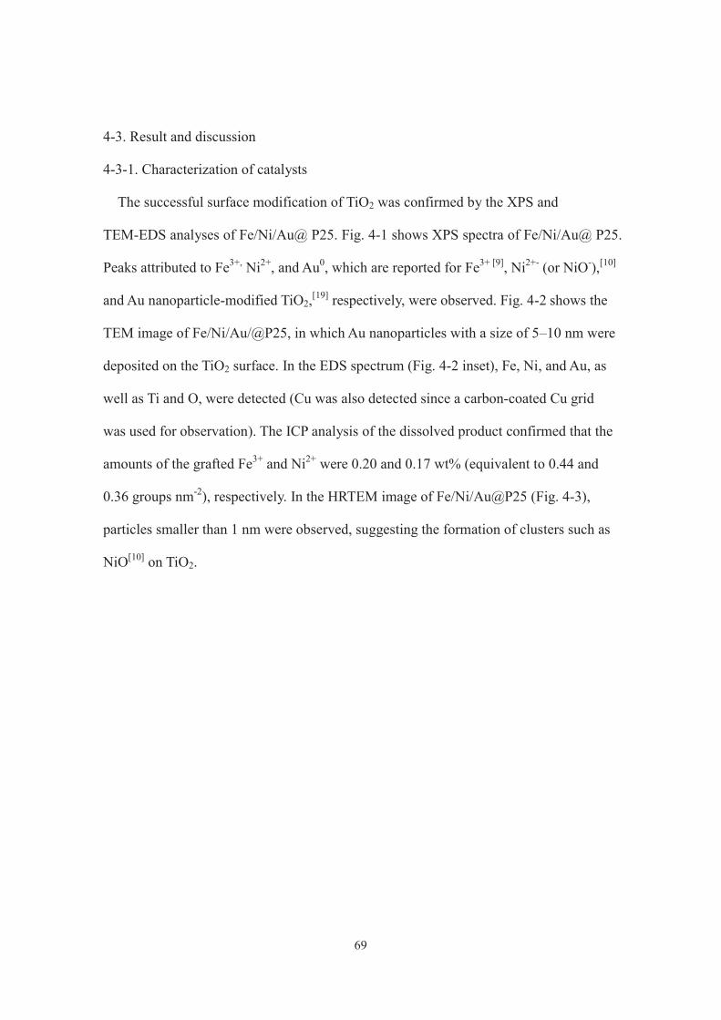
69
4-3. Result and discussion
4-3-1. Characterization of catalysts
The successful surface modification of TiO2 was confirmed by the XPS and
TEM-EDS analyses of Fe/Ni/Au@ P25. Fig. 4-1 shows XPS spectra of Fe/Ni/Au@ P25.
Peaks attributed to Fe3+, Ni2+, and Au0, which are reported for Fe3+ [9], Ni2+- (or NiO-),[10]
and Au nanoparticle-modified TiO2,[19] respectively, were observed. Fig. 4-2 shows the
TEM image of Fe/Ni/Au/@P25, in which Au nanoparticles with a size of 5–10 nm were
deposited on the TiO2 surface. In the EDS spectrum (Fig. 4-2 inset), Fe, Ni, and Au, as
well as Ti and O, were detected (Cu was also detected since a carbon-coated Cu grid
was used for observation). The ICP analysis of the dissolved product confirmed that the
amounts of the grafted Fe3+ and Ni2+ were 0.20 and 0.17 wt% (equivalent to 0.44 and
0.36 groups nm-2), respectively. In the HRTEM image of Fe/Ni/Au@P25 (Fig. 4-3),
particles smaller than 1 nm were observed, suggesting the formation of clusters such as
NiO[10] on TiO2.
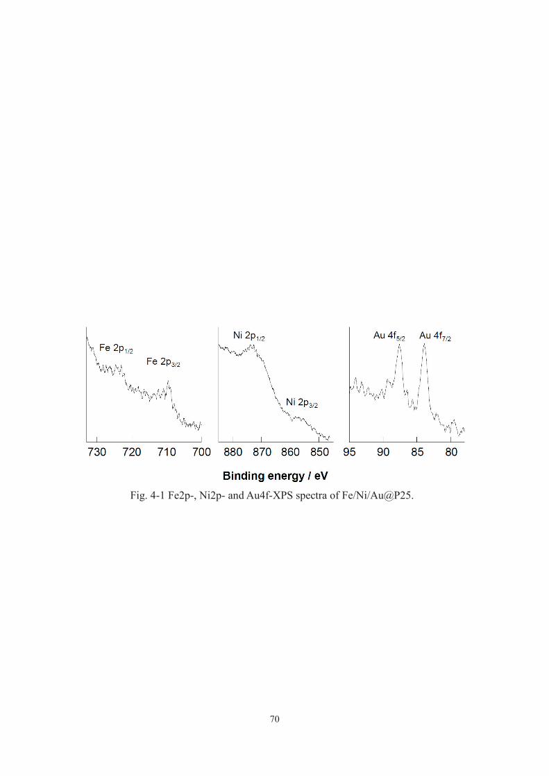
70
Fig. 4-1 Fe2p-, Ni2p- and Au4f-XPS spectra of Fe/Ni/Au@P25.
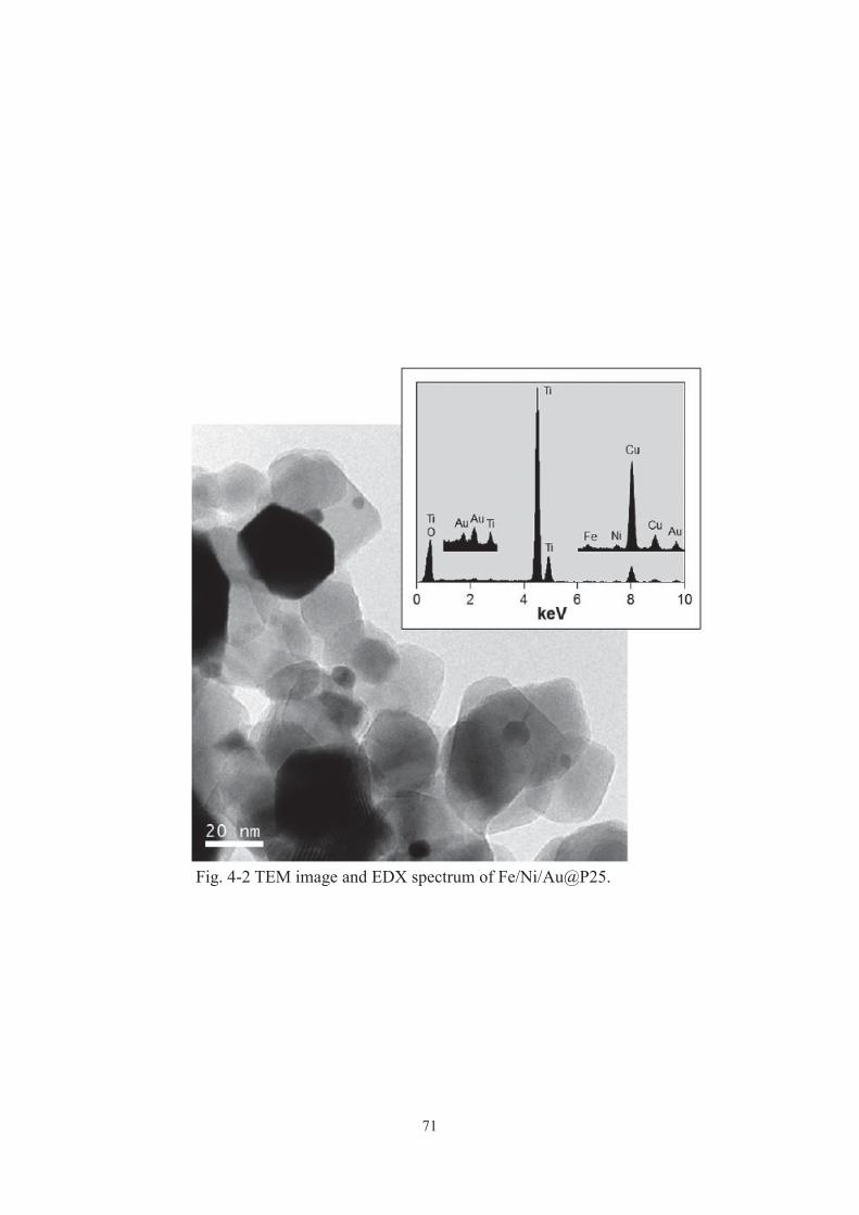
71
Fig. 4-2 TEM image and EDX spectrum of Fe/Ni/Au@P25.

72
Fig. 4-3 HRTEM image of Fe/Ni/Au@P25. Dashed circle indicates
typical particles smaller than 1 nm.
5 nm

73
4-3-2. Photocatalytic and adsorption test
Photocatalytic test
The photocatalytic cyclohexane (named as CHA) conversions were carried out under
photoirradiation of Fe/Ni/Au@P25, Ni@P25, Au@P25, Fe/Ni@P25 and pristine P25 in
an O2-saturated acetonitrile solution containing cyclohexane by a simulated solar light.
Table 4-1 summarizes the yields of cyclohexanone (named as CHA-one), cyclohexanol
(named as CHA-ol), and CO2 (only the three compounds were detected in gas
chromatography), and the efficiency and selectivity for the partial oxidation. With P25,
Ni@P25, Au@P25 or Fe/Ni@P25, the amount of CO2 evolved was much larger than
those of CHA-one and CHA-ol (Table 4-1, entries 1–4), indicating that the once-formed
CHA-one and CHA-ol were successively decomposed to CO2.[20] On the other hand,
under the identical conditions, Fe/Ni/Au@P25 produced CHA-one and CHA-ol with
91% selectivity (entry 5). It should be noted here that Fe/Ni/Au@P25 gave a high
selectivity (91%) even at a cyclohexane conversion (0.97%) higher than that (0.94%)
attained on TiO2 (entries 1 and 5). Such high activity observed on Fe/Ni/Au@P25 is
worth mentioning, because (i) a >90% selectivity at cyclohexane conversion up to 1%
has never been reported for heterogeneous photocatalytic systems and (ii) in the current
commercial aerobic oxidation process CHA conversion is kept at 4% to give 70–85%
partial oxidation selectivity.[21] Furthermore, Fe/Ni/Au@P25 was reusable for further
reactions: typically, the catalyst recovered after reaction (entry 5), when used after
simple washing with acetonitrile, showed almost the same cyclohexane conversion and
partial oxidation selectivity as the virgin catalyst (entry 6). All the results obtained
indicate high oxidation selectivity and efficiency of Fe/Ni/Au@P25.

74
The mechanism of the highly active Fe/Ni/Au@P25 was considered. Depicted in Fig.
4-4 is the UV-Vis diffused reflectance spectrum of Fe/Ni/Au@P25 together with those
of Fe/Ni@P25, Ni@ P25, Au@P25, P25, and Fe@P25). After the modification with
Fe3+ or Ni2+, TiO2 absorbed visible light at around 420 nm. Similar phenomena have
been reported for Fe3+- or Ni2+-modified TiO2 obtained by procedures that were used to
prepare the present Fe@P25 and Ni@P25 and thus explained by the formation of the
surface d sub-band of the grafted Fe or Ni species.[18, 10] Noticeably, the co-modification
of TiO2 with Fe3+ and Ni2+ further broadened the visible light absorption. The action
spectrum of CHA-one and CHA-nol formation on Fe/Ni@P25 was in good agreement
with the UV-Vis spectrum of Fe/Ni@P25 (Fig. 4-5). Therefore, Fe/Ni@P25 gave higher
CHA conversion than Ni@P25 (Table 4-1, entries 2 and 3) due to the broadening of
visible light absorption spectra. CHA conversion on Fe/Ni@P25 (and Ni@P25) was
considerably lower than that on P25 (Table 4-1, entries 1–3), which is explained as
follows. In the photocatalytic formation of CHA-one and CHA-ol on TiO2, the
cyclohexyl radical, formed by the reaction of cyclohexane with either the valence band
hole or the hydroxyl radical derived from the reduction of OH- with the valence band
hole, is considered to be a key intermediate and is oxidized by oxidizing species such as
the hydroxyl radical and the superoxide anion, which is generated by the reduction of
O2 with the conduction band electron, to give CHA-one and CHA-ol. [22] When
Fe/Ni@P25 absorbs the visible light spectrum of sunlight, electrons in the surface d
sub-bands of the grafted Fe and Ni are excited to the conduction band of TiO2, leaving
holes in the surface d sub-bands.[18] The absorption of the UV light spectrum of sunlight
by Fe/Ni@P25 leads to electron excitation from the valence band of TiO2 to the
conduction band and the generated holes can transfer from the valence band to the

75
surface d subbands.[18] The excited electrons effectively reduce O2 to the superoxide
anion. On the other hand, the hole oxidation power of the surface d sub-bands is
considerably lower than that of TiO2.[18, 16] Accordingly, when irradiated by sunlight
(UV and visible light), Fe/Ni@P25 (and Ni@P25) forms a smaller amount of oxidizing
species than P25, giving lower cyclohexane conversion. The co-modification of TiO2
with Fe3+ and Ni2+, therefore, caused both the broadening of light absorption and the
modulation of the oxidation power.
Next, the role of Au nanoparticles in the photocatalysis of Fe/Ni/Au@P25 was
considered. As can been seen in Fig. 4-6, the action spectrum of CHA-one and CHA-ol
formation on Fe/Ni/Au@P25 was in agreement with the UV-Vis spectrum of
Fe/Ni@P25 rather than Fe/Ni/Au@P25. Au nanoparticles also did not enhance the UV
light-induced activity of TiO2 for the present reaction, which was revealed by the fact
that CHA conversion of P25 was higher than that of Au@P25 (Table 4-1, entries 1 and
4). Although modifying TiO2 with Au nanoparticles has been known to enhance the UV
light-induced activity and impart the visible light response activity,[11-13] in the present
case, I should consider other reasons for more effective and selective CHA oxidation on
Fe/Ni/Au@P25 than Fe/Ni@P25 (Table 4-1, entries 3 and 5). Fig. 4-7 depicts the
time-dependent change in the yield of CHA-one, CHA-ol, and CO2 during the
photooxidation of cyclohexane over P25, Fe/Ni@P25, and Fe/Ni/Au@P25. During a
relatively short irradiation period (>6 h), Fe/Ni@P25 and Fe/Ni/Au@P25 exhibited
similar yields of CHA-one, CHA-ol, and CO2. However, when irradiated for a longer
time, Fe/Ni/Au@P25 showed the increase of CHA-one and CHA-ol yields with the
suppression of CO2 formation, which was due to the inhibition of the successive
oxidation of the partially oxidized products. This factor is discussed in the next section.

76
Table 4-1 Oxidation of cyclohexane (CHA) to cyclohexanone (CHA-one) and
cyclohexanol (CHA-ol) under simulated solar lighta.
CHA con- [CHA-one + CHA-ol]
CHA-one CHA-ol CO2 version / % selectivity / %
1 TiO2 (P25) 93.4 14.2 399.8 0.94 62
2 Ni@P25 7.1 9.6 102.7 0.18 49
3 Fe/Ni@P25 14.4 8.4 136.4 0.25 50
4 Au@P25 37.8 11.1 162.6 0.41 64
5 Fe/Ni/Au@P25 82.5 80.0 99.0 0.97 91
6 Fe/Ni/Au@P25 82.3 80.4 97.9 0.97 91
CatalystYield / μmol
Entry b c
a Reaction conditions: substrate, cyclohexane (2 mL); solvent, acetonitrile (18 mL)
saturated with O2; catalyst, 30 mg; simulated solar light (λ > 320 nm) irradiation time,
24 h; temperature, 42 ˚C. b {[Formed CHA-one] + [formed CHA-ol] + 1/6[formed
CO2]}/[added CHA] 100. c {[Formed CHA-one] + [formed CHA-ol]}/{[formed
CHA-one] + [formed CHA-ol] + 1/6[formed CO2]} 100. d Reused after washing
with acetonitrile.
d
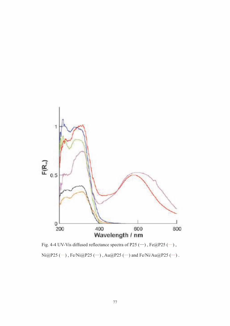
77
Fig. 4-4 UV-Vis diffused reflectance spectra of P25 ( ) , Fe@P25 ( ) ,
Ni@P25 ( ) , Fe/Ni@P25 ( ) , Au@P25 ( ) and Fe/Ni/Au@P25 ( ) .
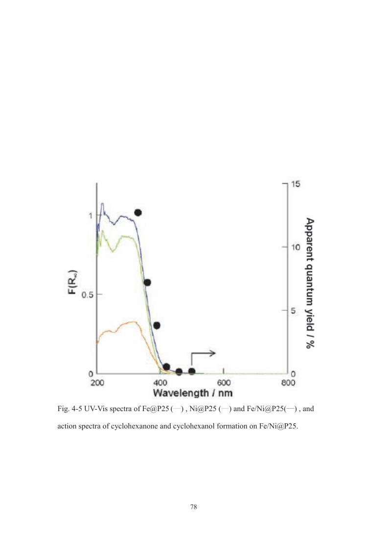
78
Fig. 4-5 UV-Vis spectra of Fe@P25 ( ) , Ni@P25 ( ) and Fe/Ni@P25( ) , and
action spectra of cyclohexanone and cyclohexanol formation on Fe/Ni@P25.
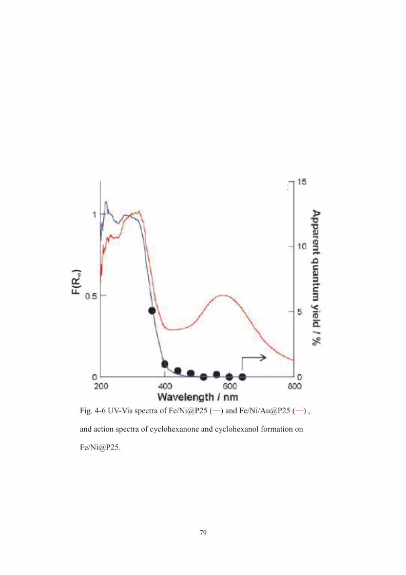
79
Fig. 4-6 UV-Vis spectra of Fe/Ni@P25 ( ) and Fe/Ni/Au@P25 ( ) ,
and action spectra of cyclohexanone and cyclohexanol formation on
Fe/Ni@P25.
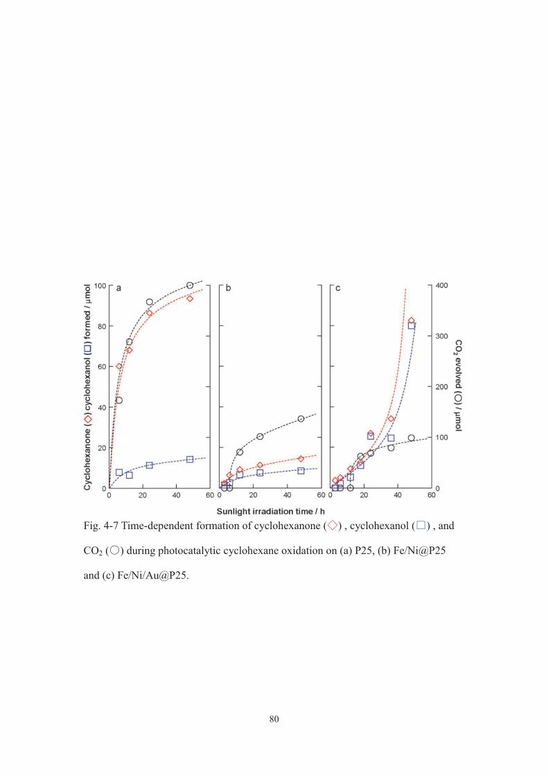
80
Fig. 4-7 Time-dependent formation of cyclohexanone ( ) , cyclohexanol ( ) , and
CO2 ( ) during photocatalytic cyclohexane oxidation on (a) P25, (b) Fe/Ni@P25
and (c) Fe/Ni/Au@P25.
81
Adsorption of CHA-one on photocatalysts
To confirm above hypothesis, suppression of the successive oxidation of the partially
oxidized products, I examined the adsorption of a product CHA-one on Fe/Ni/Au@P25.
Fig. 4-8 compares the adsorption isotherm of CHA-one from an acetonitrile solution
containing CHA and CHA-one on Fe/Ni/Au@P25 with those on P25, Fe/Ni@P25, and
Au@P25. It was apparent that when modified with Au nanoparticles, P25 adsorbed a
smaller amount of CHA-one. Accordingly, Fe/Ni/Au@P25 desorbs the once-formed
CHA-one (and CHA-ol) easily, as compared to Fe/Ni@P25, to prevent the successive
oxidation, giving a larger amount of CHA-one and CHA-ol and a smaller amount of
CO2. It is difficult to clearly explain a reason for improved desorption of CHA-one from
TiO2 after the modification with Au nanoparticles at this point. However, it has been
reported that the amount of surface titanol, which can interact with cyclohexanone, on
TiO2 is dramatically reduced during the deposition of Au nanoparticles on the surface.
[14, 15] I cannot rule out the possibility that cluster-level Au particles (Fig. 4-3) effectively
occupy the surface titanol group of TiO2.

82
Fig. 4-8 Adsorption isotherms of cyclohexanone from an acetonitrile
solution containing cyclohexane and cyclohexanone on P25 ( ) ,
Fe/Ni@P25 ( ) , Au@P25 ( ) and Fe/Ni/Au@P25 ( ) .
CH
A-o
ne a
dsor
bed
/ μm
olg-1
Equilibrium concentration / μmol L-1
00 0.0005 0.001 0.0015 0.002
0.0005
0.001
0.0015
0.002
0.0025Fe/Ni@P25
P25
Au@P25
Fe/Ni/Au@P25

83
4-4. Conclusion
The surface modification of TiO2 with Fe3+, Ni2+, and Au nanoparticles has given rise
to a noticeable photocatalytic activity for selective cyclohexane oxidation with O2 under
sunlight irradiation.[23] The surface modification of TiO2 with three kinds of functional
units can be a simple and useful way to attain green organic synthesis.

84
4-5. References
[1] M. A. Fox and M. Dulay, Chem. Rev., 1993, 93, 341.
[2] A. Maldotti, A. Molinari and R. Amadelli, Chem. Rev., 2002, 102, 3811.
[3] Y. Shiraishi and T. Hirai, J. Photochem. Photobiol. C, 2008, 9, 157.
[4] O. Tomita, R. Abe and B. Ohtani, Chem. Lett., 2011, 1405.
[5] S. Fukukawa, T. Shishido, K. Teramura and T. Tanaka, ACS Catal., 2012, 2, 175.
[6] T. Ikeda, T. Nomoto, K. Eba, Y. Mizutani, H. Kato, A. Kudo and H. Onishi, J. Phys.
Chem. C, 2008, 112, 1167.
[7] H. Tada, T. Mitsui, T. Kiyonaga, T. Akita and K. Tanaka, Nat. Mater., 2006, 5, 782.
[8] D. Kuang, P. Walter, F. Nuuesch, S. Kim, J. Ko, P.Comte, S. M. Zakeeruddin, M. K.
Nazeeryddin and M. Gratzel, Langmuir, 2007, 23, 10906.
[9] H. Yu, H. Irie, Y. Shimodaira, Y. Hosogi, Y. Kuroda, M. Miyauchi and K. Hashimoto,
J. Phys. Chem. C, 2010, 114, 16481.
[10] Q. Jin, T. Ikeda, M. Fujishima and H. Tada, Chem. Commun., 2011, 21, 20.
[11] H. Tada, T. Kiyonaga and S. Naya, Chem. Soc. Rev., 2009, 38, 1849.
[12] Y. Tian and T. Tatsuma, J. Am. Chem. Soc., 2005, 127, 7632.
[13] E. Kowalska, R. Abe and B. Ohtani, Chem. Commun., 2009, 241.
[14] J. T. Carneiro, C.-C. Yang, J. A. Moma, J. A. Moulijn and G. Mul, Catal. Lett.,
2009, 129, 12.
[15] Y. Ide, R. Ogino, M. Sadakane and T. Sano, ChemCatChem, 2013, 5, 766.
[16] Y. Ide, H. Hattori, S. Ogo, M. Sadakane and T. Sano, Green Chem., 2012, 14, 1264.
[17] C. G. Silva, R. Juarez, T. Marino, R. Molinari and H. Garcia, J. Am. Chem. Soc.,
2011, 133, 595.

85
[18] H. Tada, Q. Jin, H. Nishijima, H. Yamamoto, M. Fujishima, S. Okuoka, T. Hattori,
Y. Sumida and H. Kobayashi, Angew. Chem. Int. Ed., 2011, 50, 3501.
[19] D. Tsukamoto, Y. Shiraishi, Y. Sugano, S. Ichikawa, S. Tanaka and T. Hirai, J. Am.
Chem. Soc., 2012, 134, 6309.
[20] D. Tsukamoto, A. Shiro, Y. Shiraishi and T. Hirai, J. Phys. Chem. C, 2011, 115,
19782.
[21] Y. Shiraishi, N. Saito and T. Hirai, J. Am. Chem. Soc., 2005, 127, 12820.
[22] C. B. Almquist and P. Biswas, Appl. Catal. A, 2001, 214, 259.
[23] Y. Ide, N. Kawamoto, Y. Bando, H. Hattori, M. Sadakane and T. Sano, Chem.
Commun., 2013, 49, 3652.
86
Chapter 5
Efficient and selective photocatalytic cyclohexane oxidation on a layered titanate
modified with iron oxide under sunlight and CO2 atmosphere
5-1. Introduction
Designing novel photocatalysts for effective and selective synthesis of fine chemicals
has been extensively investigated in recent years. A great deal of endeavor has been
spent on modifying TiO2 by heteroelemental doping and hybridization with organic
dyes and nanoparticles as well as designing novel catalysts, such as molecular-sieve-like
TiO2 and non-TiO2 materials. [1-5] In particular, iron doping and iron or iron oxide
modification of TiO2 has merit in that iron is also harmless and abundant in nature;
however, only a limited number of works have been reported to attain increased UV
light-induced activity and visible light response of TiO2,[6, 7] which are necessary for the
application under sunlight. Moreover, there are few reports on photocatalytic synthetic
reactions over such materials under sunlight.[8]
Utilization of nanostructured TiO2 is a useful way for catalytic function design.
Shiraishi et al. reported that the oxidation of benzene to phenol selectively progressed
using mesoporous TiO2[9]. It is concluded that selective oxidation was promoted because
the benzene of the substrate was adsorbed to the catalyst, but phenol as the product was
easily released from the catalyst and sequential oxidation was suppressed. Moreover,
structural design using layered titanate has also been reported. Layered titanate
incorporates substances into layers by intercalation. Specific structure and functional
design are possible depending on the type and amount of the interlayer functional unit,
so selective organic synthesis is also possible. [10-12] Ide et al. reported that the interlayer

87
distance of potassium lithium titanate with hydration by changing the interlayer K+ to
Li+ or Na+ caused molecular recognition-like adsorption, so benzene is selectively
adsorbed and disassembled from a mixed aqueous solution of benzene, phenol and
4-butylphenol.[13] Layered titanate responds only to ultraviolet light, but by
incorporating a substance having visible light absorption, it can be applied as a
photocatalyst having visible light activity. Ide et al. reported conversion of benzene to
phenol was carried out by visible light irradiation with a catalyst in which gold was
pillared between layers of layered titanate.[11] Choy et al. reported efficient
decomposition of organic compounds in water under visible light irradiation by
supporting a cluster of chromium oxide that absorbs visible light between layers of
layered titanate.[14]
In this chapter, the interlayer of the layered titanate was modified with iron, and the
obtained product was applied to perform the partial oxidation reaction of cyclohexane
which is an industrially important reaction under simulated sunlight irradiation.
Moreover, this photocatalytic reaction was carried out under a CO2 atmosphere reported
in Chapter 2 to further improve the catalytic activity.
88
5-2. Experimental
Reagents and materials
P25 was supplied by Nippon Aerosil. K2CO3, LiCO3, acetone, Iron( ) acetylacetonate
(Fe(acac)3), ethanol, toluene, hexane and hydrochloric acid were purchased from Wako
Pure Chemical Industries, Ltd. Cyclohexane (named as CHA) and acetonitrile were
purchased from Nacalai tesque Ltd. Dodecyl amine hydrochloride and cyclohexanone
were purchased from Tokyo Kasei Ind. Co., Ltd. All reagents and materials were used as
received.
Synthesis of photocatalyst[15, 16]
A layered titanate, K0.7Ti1.73Li0.27O4 (named KTLO), was reacted with an aqueous
solution of dodecylammine hydrochloride (>97%, Tokyo Chemical Industry Co., Ltd.)
according to the reported procedure to prepare the dodecylammonium-exchanged
layered titanate (named C12N+-TLO). C12N+-TLO (0.6 g (2.9 × 10⁻³ mol)) was added to
a solution of Fe(III) acetylacetonate complex (named Fe(acac)3, Wako Pure Chemical
Industries, Ltd.) in a mixed solvent (200 mL, ethanol/hexane = 3:17 v/v), and the
mixture was stirred at room temperature for 3 days. The product was separated by
centrifugation (3500 rpm, 20 min), washed repeatedly with the same solvent, and then
washed with a mixed solution of ethanol and 0.1 mol L−1 of aqueous hydrogen chloride
(1:1 v/v). The amount of the added Fe(acac)3 was tuned (1.5 × 10⁻³ or 2.9 × 10⁻³ mol) to
control the amount of the attached Fe(acac)3 on the titanate. The iron oxide-modified
layered titanate thus obtained was named FeOx-TLO, where x denoted the number of
the attached Fe (groups) per a unit cell of K0.7Ti1.73Li0.27O4. The layered titanate in
which only the particle outer surface was modified with iron oxide (named
89
FeO@KTLO) and a commercially available TiO2 (Aerosil P25) modified with iron
oxide (named FeO@P25) were synthesized in a way similar to that in the synthesis of
FeOx-TLO, except that pristine KTLO and P25 were used, respectively, and the
products after Fe(acac)3 adsorption were washed with the ethanol/hexane mixed solvent
and then calcined at 500 °C for 1 h.
Photocatalytic tests
A mixture of catalyst (30 mg) and O2-saturated acetonitrile (18 mL) solution of
cyclohexane (2 mL) in a stainless-made closed container equipped with Pyrex glass (75
mL) was irradiated with solar simulator (San-Ei Electric Co., Ltd.) at 42 °C, under
shaking. The container was placed 30 cm away from the light source to irradiate 1
solar (1000 W m−2)-power light to the mixture. After the reaction, the gas-phase product
was analyzed by GC-TCD (Shimazu GC-8A). The solution was mixed with toluene (as
internal standard) and then recovered by filtration, and the resulting supernatant was
analyzed by GC-FID (Shimazu GC-2014). Only three products, cyclohexanone,
cyclohexanol, and CO2, were detected in the present study. The intermediates, such as
cyclohexyl hydroperoxide, were not detected.Oxidation of cyclohexane.
Adsorption tests
Adsorption was done in a way similar to that conducted in the photocatalytic
conversions except that 10 mg ( 30 μmol) of the catalyst and a mixed solution (20 mL)
of cyclohexane and cyclohexanone ( 90 μmol for each compound) in acetonitrile,
which was not bubbled with O2, were shaken in the dark at room temperature for 6 h.
Apparent quantum yield measurement.
90
The full arc from a 500 W Xe lamp (Ushio) was monochromated using SM-25
(Bunkoukeiki) and then used to irradiate a mixture of catalyst (30 mg) and O2-saturated
acetonitrile (18 mL) solution of cyclohexane (2 mL) in the container. The light intensity
of the monochromated Xe lamp was determined using a spectroradiometer, USR-45D
(Ushio).
Materials characterization.
X-ray diffraction (XRD) patterns of solid products were collected using a powder
Xray diffractometer (Bruker D8 Advance) with graphitemonochromatized Cu K
radiation at 40 kV and 30 mA. UV vis spectra were recorded with a Jasco V-579
UV/vis/NIR spectrophotometer. X-ray photoelectron spectra (XPS) were taken with
a Kratos ESCA-3400 electron spectrometer, where the binding energies were
calibrated by the O 1s peak. Thermogravimetric-differential thermal analysis (TG-DTA)
curves were collected using a SSC/5200 apparatus (Seiko Instruments). The sample was
heated from room temperature to 800 °C in an air flow (50 mL min 1) at a rate of 10 °C
min 1. The crystalmorphology of products was observed by scanning electron
microscopy (SEM, Hitachi S-4800), and the elemental mapping was conducted by SEM
and energydispersive X-ray analysis. Inductively coupled plasma optical emission
spectroscopy was performed on a Seiko SPS7000. The solid products were decomposed
for the measurements with an aqueous H2SO4 solution. Nitrogen adsorption isotherms at
196 °C were obtained using a conventional volumetric apparatus (BELSORP-mini, Bel
Japan). Prior to the adsorption measurements, the samples were evacuated at 120 °C for
12 h.

91
5-3. Result and discussion
5-3-1. Characterization of catalysts
The interlayer modification of KTLO with molecular-level iron oxide was performed
by adsorption with Fe(acac)3. A direct reaction between KTLO and Fe(acac)3 did not
lead the intercalation of the complex into the interlayer space; therefore, the interlayer
K+ was first exchanged with dodecylammonium cation to expand the interlayer space,
and the resulting C12N+-TLO was reacted with Fe(acac)3, followed by removal of the
dodecylammonium with washing. Similar procedures have often been employed to
introduce bulky silane coupling reagents into the interlayer space of layered silicates
and titanates.[17, 18]
The XRD patterns of KTLO, C12N+-TLO, and FeO0.13-TLO before and after the
washing are depicted in Fig. 5-1. The basal spacing (2.7 nm) of C12N+-TLO increased to
3.1 nm and then decreased to 1.3 nm after the reaction with Fe(acac)3 and the
subsequent washing, respectively. The elemental mapping of FeO0.13-TLO revealed that
Fe was not concentrated on the particle outer surface but distributed entirely within the
particle (Fig. 5-2). The XPS spectrum of the FeO0.13-TLO confirmed the presence of
Fe3+ on the surface[6, 7] (data not shown). Since Fe(acac)3 has been reported to
irreversibly react with the surface Ti−OH group to form a Ti−O−Fe covalent bond via a
ligand exchange reaction,[6] the data provided above indicate that Fe(acac)3 is
immobilized on the interlayer space of KTLO, and dodecylammonium is removed. In
the XRD pattern of the FeO0.13-TLO, the peak attributed to the (200) lattice plane of the
KTLO was observed at 49°, confirming that the structural regularity on the layered
titanate is retained after the modification with Fe(acac)3.
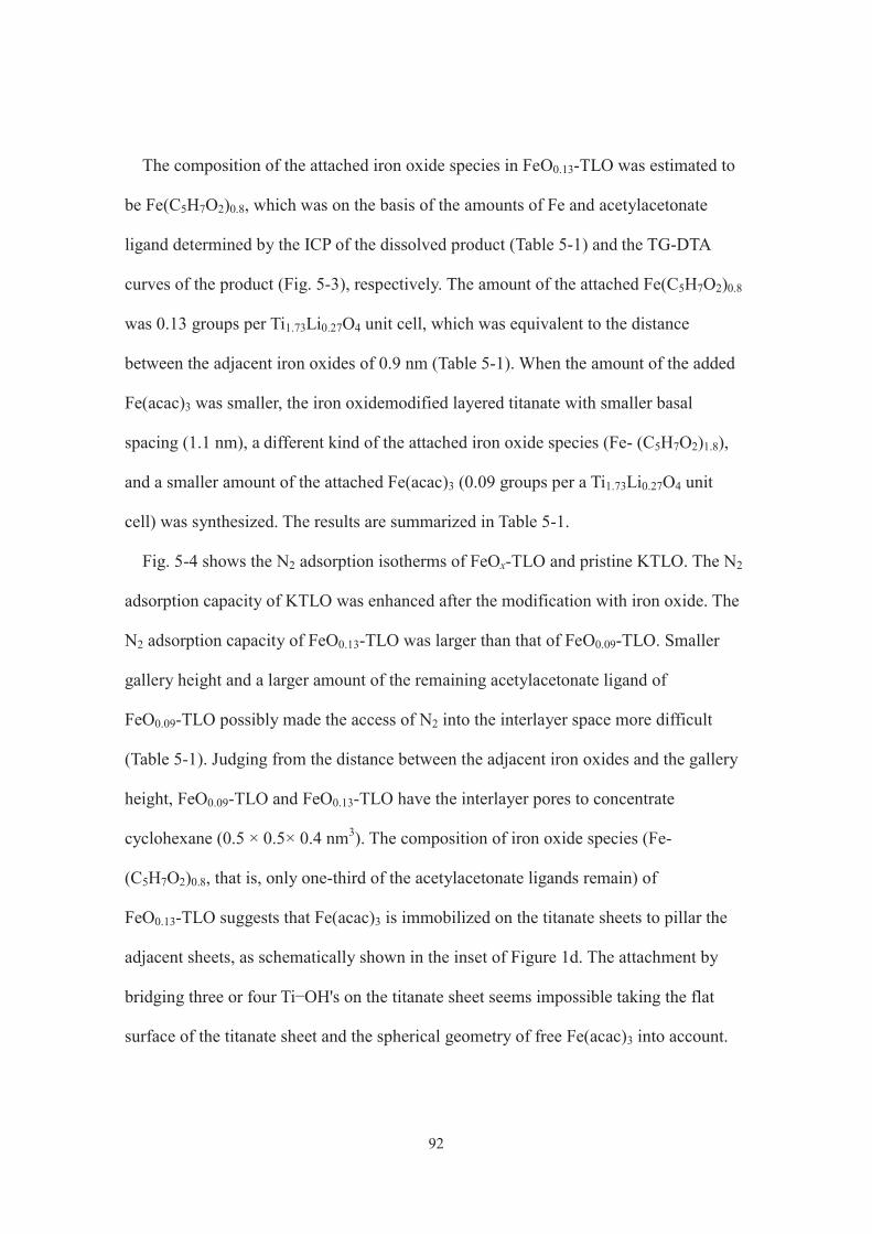
92
The composition of the attached iron oxide species in FeO0.13-TLO was estimated to
be Fe(C5H7O2)0.8, which was on the basis of the amounts of Fe and acetylacetonate
ligand determined by the ICP of the dissolved product (Table 5-1) and the TG-DTA
curves of the product (Fig. 5-3), respectively. The amount of the attached Fe(C5H7O2)0.8
was 0.13 groups per Ti1.73Li0.27O4 unit cell, which was equivalent to the distance
between the adjacent iron oxides of 0.9 nm (Table 5-1). When the amount of the added
Fe(acac)3 was smaller, the iron oxidemodified layered titanate with smaller basal
spacing (1.1 nm), a different kind of the attached iron oxide species (Fe- (C5H7O2)1.8),
and a smaller amount of the attached Fe(acac)3 (0.09 groups per a Ti1.73Li0.27O4 unit
cell) was synthesized. The results are summarized in Table 5-1.
Fig. 5-4 shows the N2 adsorption isotherms of FeOx-TLO and pristine KTLO. The N2
adsorption capacity of KTLO was enhanced after the modification with iron oxide. The
N2 adsorption capacity of FeO0.13-TLO was larger than that of FeO0.09-TLO. Smaller
gallery height and a larger amount of the remaining acetylacetonate ligand of
FeO0.09-TLO possibly made the access of N2 into the interlayer space more difficult
(Table 5-1). Judging from the distance between the adjacent iron oxides and the gallery
height, FeO0.09-TLO and FeO0.13-TLO have the interlayer pores to concentrate
cyclohexane (0.5 × 0.5× 0.4 nm3). The composition of iron oxide species (Fe-
(C5H7O2)0.8, that is, only one-third of the acetylacetonate ligands remain) of
FeO0.13-TLO suggests that Fe(acac)3 is immobilized on the titanate sheets to pillar the
adjacent sheets, as schematically shown in the inset of Figure 1d. The attachment by
bridging three or four Ti OH's on the titanate sheet seems impossible taking the flat
surface of the titanate sheet and the spherical geometry of free Fe(acac)3 into account.

93
On the other hand, Fe(acac)3 is possibly immobilized on the titanate sheet in a dipodal
fashion to leave two acetylacetonate ligands in FeO0.09-TLO.
The UV−vis diffused reflectance spectra of FeOx-TLO are depicted in Fig. 5-5,
together with that of KTLO and FeO@KTLO. FeOx-TLO showed shoulders around 420
nm and absorption bands centered at 490 nm. In the absorption spectrum of Fe(acac)3,
an absorption band due to d−d transition in the acetylacetonate ligands was observed at
430 nm (Fig. 5-5, e). On the other hand, it is difficult to assign the latter absorption
bands for FeOx-TLO. Fe(III)-grafted TiO2, prepared by the impregnation with FeCl3,
showed a weak absorption band centered around 500 nm ascribable to electron transfer
from the valence band of TiO2 to Fe3+. [7] Moreover, similar absorption bands were
observed for Fe(acac)3-modified TiO2 (P25) after calcination,[6] FeO@P25,[8] and
FeO@KTLO (Fig. 5-5, d). Therefore, the absorption around 490 nm for FeOx-TLO
implies the presence of molecular level iron oxides.
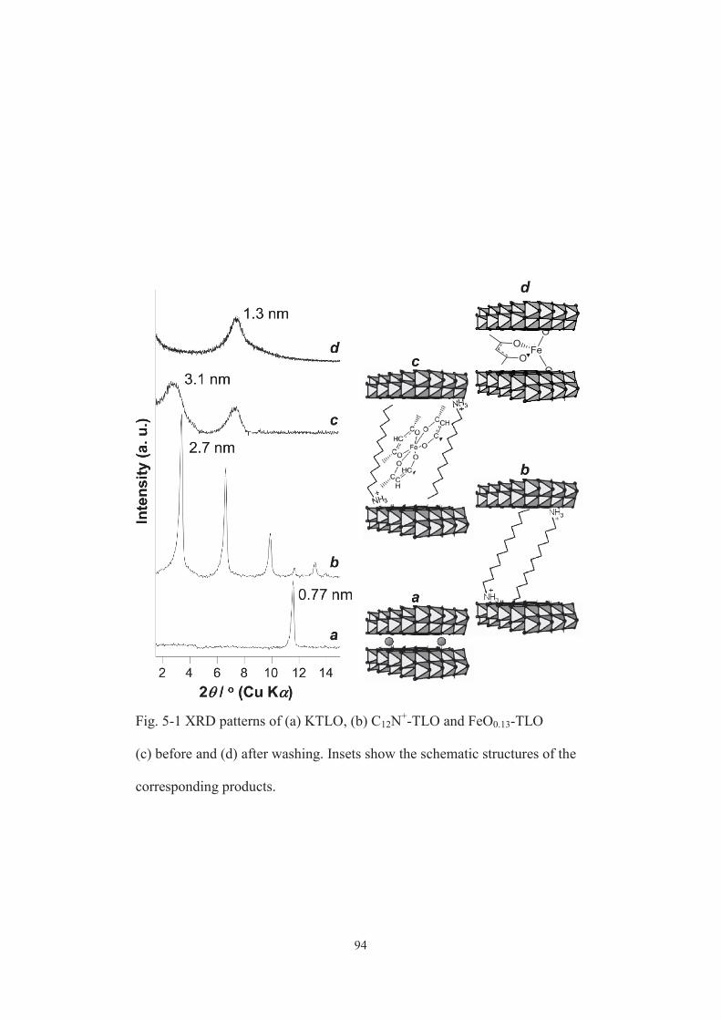
94
Fig. 5-1 XRD patterns of (a) KTLO, (b) C12N+-TLO and FeO0.13-TLO
(c) before and (d) after washing. Insets show the schematic structures of the
corresponding products.
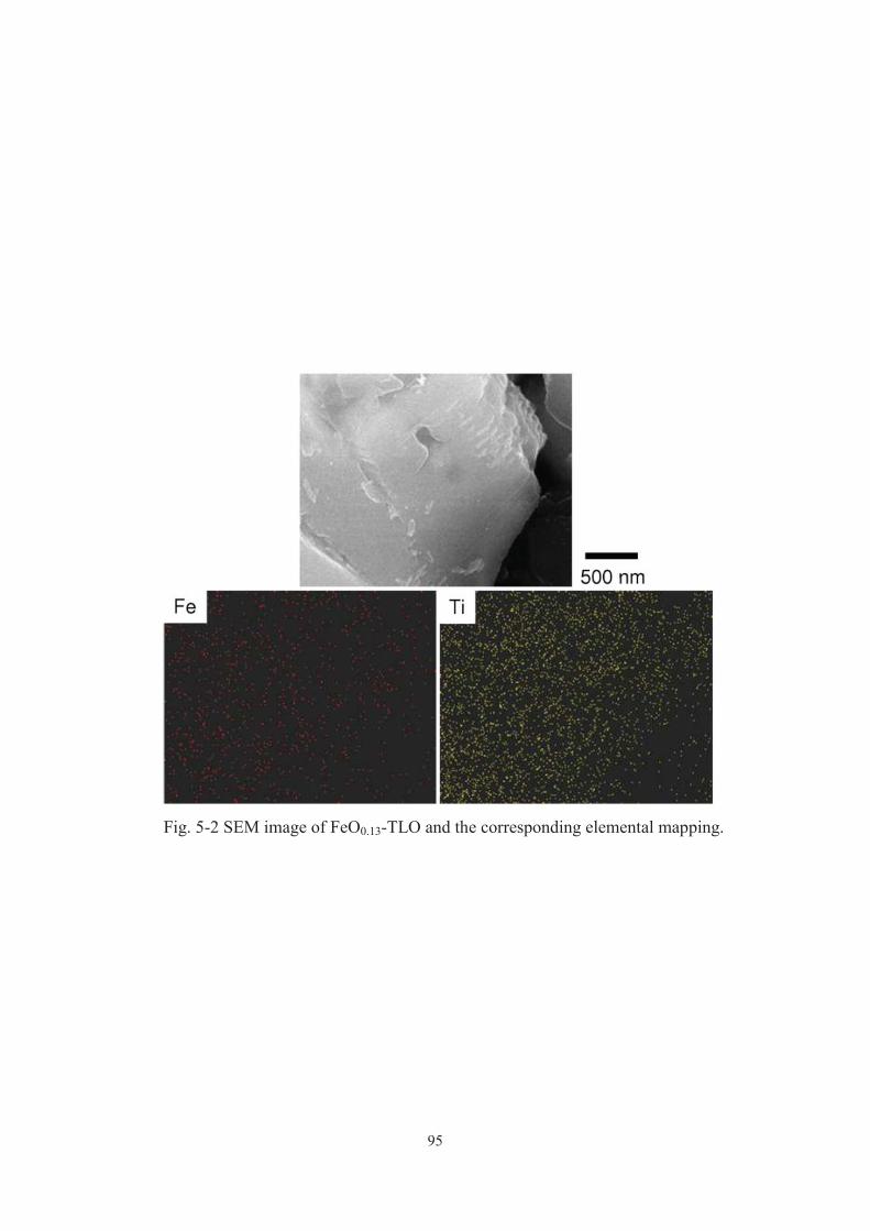
95
Fig. 5-2 SEM image of FeO0.13-TLO and the corresponding elemental mapping.

96
Fig. 5-3 TG (solid)-DTA (dashed) curves of (a) FeO0.09-TLO, and
(b) FeO0.13-TLO recorded in air.

97
Gallery height Fe-Fe/ nm distance / nm
FeO0.09-TLO 2.7 Fe(C5H7O2)1.8 0.6 1.1FeO0.13-TLO 4.0 Fe(C5H7O2)0.8 0.8 0.9
Fe / wt% Aattached FeCatalyst
a On the assumption that all mass loss from 300 to 500 °C in the TG curves of
FeOx-TLO (Fig. 5-3) is due to the oxidative decomposition of acetylacetonate ligands.
b The single layer thickness of KTLO (0.5 nm)[30] was subtracted from the observed
basal spacing. c Calculated as (2 ab/x)1/2, ab and x denote basal area of KTLO (0.38 ×
0.30 nm2) and Fe/TLO molar ratio, respectively[31].
a b c
Table 5-1 Characteristics of FeOx-TLO.
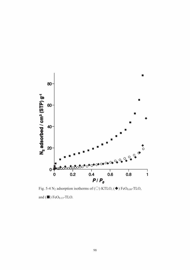
98
Fig. 5-4 N2 adsorption isotherms of ( ) KTLO, ( ) FeO0.09-TLO,
and ( ) FeO0.13-TLO.
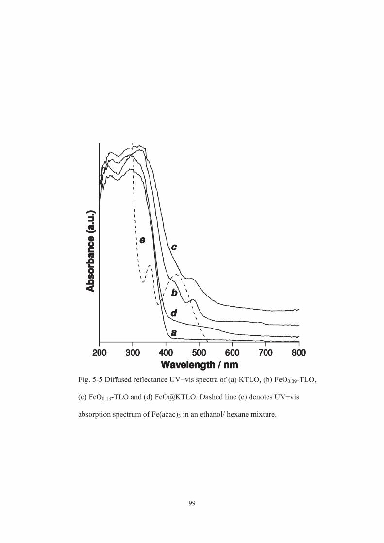
99
Fig. 5-5 Diffused reflectance UV−vis spectra of (a) KTLO, (b) FeO0.09-TLO,
(c) FeO0.13-TLO and (d) FeO@KTLO. Dashed line (e) denotes UV−vis
absorption spectrum of Fe(acac)3 in an ethanol/ hexane mixture.

100
5-3-2. Photocatalytic and adsorption tests
Cyclohexane oxidation
To assess a high level of photocatalytic activity of FeOx-TLO toward selective
cyclohexane (named as CHA) oxidation under sunlight, the activity of FeOx-TLO was
compared with those of a commercially available TiO2 (P25), FeO@P25[8] and
FeO@KTLO under the same irradiation conditions and with the same amount of
photocatalysts (Table 5-2). FeOx-TLO showed selectivity up to 100% (Table 5-2, entries
1, 2, 5, and 8), which was considerably higher than that obtained on P25 (Table 5-2,
entry 9). The extremely high selectivity resulted from the suppression of CO2 evolution.
FeO0.13-TLO gave the best result, with the conversion comparable to that obtained on
P25 (Table 5-2, entries 5, 8, and 9).
To the best of our knowledge, the activity obtained on FeO0.13-TLO at 6 h of sunlight
irradiation (0.14% conversion, 100% selectivity, and 28% apparent quantum yield at
380 nm) was superior or comparable to those that had been reported for photocatalytic
cyclohexanone (named as CHA-one) and cyclohexanol (named as CHA-ol) production
under visible light,[19, 20] although the present material is cheap and abundant. For
example, 0.09% conversion and >99% selectivity were obtained on Cr/Ti/Si ternary
mixed oxide[20]. The activity of FeO@P25[8] was lower than that of FeOx-TLO under
identical conditions (Table 5-2, entries 2, 5, 8, 10, and 11), showing a merit of the
presently proposed material design. Further improvement of the photocatalytic activity
of FeOx-TLO seems possible by controlling reaction environments, since I have
reported the positive effects of a reaction environment (as described in chapters 2 and3),
such as the presence of a target product in the starting mixture[11] and CO2
atmosphere,[21, 8] on photocatalytic selective oxidations. Indeed, CHA conversion of

101
FeOx-TLO was substantially improved, with 100% selectivity maintained by conducting
the reaction under a CO2 atmosphere (Table 5-2, entries 1, 4, 5, and 7). The XRD
patterns and the UV−vis spectra of FeOx-TLO did not change after the photocatalytic
reaction, and Fe was not detected by the UV−vis absorption spectra of the supernatant
after the reaction. Therefore, FeOx-TLO was stable during the present photocatalysis. As
a result, it could be reused without loss of the original activity (Table 5-2, entries 5 and
6), which was a merit for the practical application.
When sunlight only with wavelength longer than 420 nm was used to irradiate
FeO0.09-TLO, CHA-one, CHA-ol and CO2 hardly formed (Table 5-2, entry 3). Therefore,
the attached Fe(acac)3 did not work as a visible light harvester. It should be noted here
that the presently designed FeOx-TLO effectively photocatalyzes CHA using only the
UV spectrum of sunlight. It has been suggested that in TiO2 modified with molecular
level iron oxide, the iron oxide accepts electrons generated by the band gap excitation of
TiO2 to improve the charge separation efficiency.[6,8]
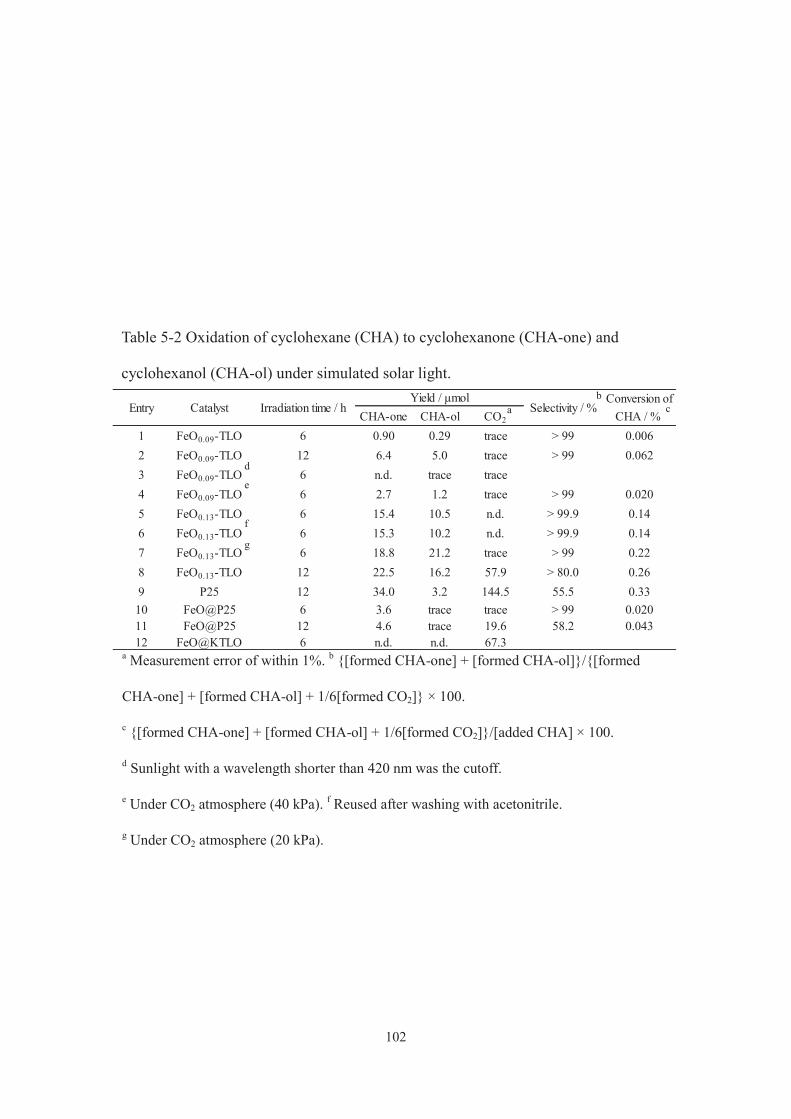
102
Conversion ofCHA-one CHA-ol CO2 CHA / %
1 FeO0.09-TLO 6 0.90 0.29 trace > 99 0.0062 FeO0.09-TLO 12 6.4 5.0 trace > 99 0.0623 FeO0.09-TLO 6 n.d. trace trace4 FeO0.09-TLO 6 2.7 1.2 trace > 99 0.0205 FeO0.13-TLO 6 15.4 10.5 n.d. > 99.9 0.146 FeO0.13-TLO 6 15.3 10.2 n.d. > 99.9 0.147 FeO0.13-TLO 6 18.8 21.2 trace > 99 0.228 FeO0.13-TLO 12 22.5 16.2 57.9 > 80.0 0.269 P25 12 34.0 3.2 144.5 55.5 0.3310 FeO@P25 6 3.6 trace trace > 99 0.02011 FeO@P25 12 4.6 trace 19.6 58.2 0.04312 FeO@KTLO 6 n.d. n.d. 67.3
Yield / μmolSelectivity / %Irradiation time / hCatalystEntry
Table 5-2 Oxidation of cyclohexane (CHA) to cyclohexanone (CHA-one) and
cyclohexanol (CHA-ol) under simulated solar light.
a Measurement error of within 1%. b {[formed CHA-one] + [formed CHA-ol]}/{[formed
CHA-one] + [formed CHA-ol] + 1/6[formed CO2]} × 100.
c {[formed CHA-one] + [formed CHA-ol] + 1/6[formed CO2]}/[added CHA] × 100.
d Sunlight with a wavelength shorter than 420 nm was the cutoff.
e Under CO2 atmosphere (40 kPa). f Reused after washing with acetonitrile.
g Under CO2 atmosphere (20 kPa).
a b
c
d
e
f
g
103
Adsorption test of CHA and CHA-one
The roles of the immobilized iron oxide species of FeOx- TLO in the present
photocatalytic CHA oxidation were discussed. When FeOx-TLO was mixed with a
mixture of CHA and CHA-one in the dark, CHA was selectively adsorbed depending on
the amount of Fe (Table 5-3). The surface Ti−OH (which can interact with CHA-one
and CHA-ol) on FeOx-TLO is occupied with iron oxide species so effectively that
interactions between the catalysts and the partially oxidized products are relatively weak.
Accordingly, the photocatalytically formed CHA-one and CHA-ol promptly desorb
from the active center (interlayer spaces) of FeOx-TLO, giving the effective and
selective formation of the products. As shown in Table 5-2 (entry 12), only trace
amounts of CHA-one and CHA-ol formed on FeO@KTLO that did not adsorb CHA
effectively. This result supports the above idea. FeO0.13-TLO adsorbs CHA more
effectively than FeO0.09-TLO due to the larger surface area, giving higher CHA
conversion. Studies on the catalytic or photocatalytic conversion of organic substrates
using zeolites[22] and mesoporous materials[23,11,24] have demonstrated that the separation
of target products from the catalysts plays an important role in the efficient formation of
the products. Further studies on the nanostructural design of FeOx-TLO by changing the
amount of the attached Fe(acac)3 and coimmobilizing other functional units[25, 26] are
worth conducting to optimize the molecular recognition ability and then the
photocatalytic performance.
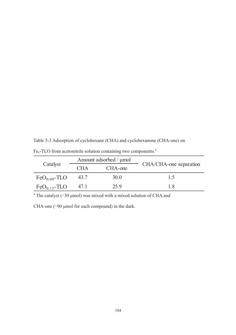
104
Table 5-3 Adsorption of cyclohexane (CHA) and cyclohexanone (CHA-one) on
Fex-TLO from acetonitrile solution containing two components.a
a The catalyst ( 30 μmol) was mixed with a mixed solution of CHA and
CHA-one ( 90 μmol for each compound) in the dark.
CHA CHA-one
FeO0.09-TLO 43.7 30.0 1.5
FeO0.13-TLO 47.1 25.9 1.8
CHA/CHA-one separationAmount adsorbed / μmol
Catalyst
105
5-3-3. Catalytic reaction mechanism
Fig. 5-6 shows the time-dependent change in the yields of CHA-one, CHA-ol, and
CO2 during the photocatalytic CHA oxidation over FeO0.09-TLO. Almost equivalent
amounts of CHA-one and CHA-ol formed, and a much smaller amount of CO2 evolved.
From all the results obtained, a possible mechanism for the present reaction was
proposed as follows: First, the intercalated CHA is reacted with either a hole or OH• (or
OH2•), which are photogenerated on the titanate valence band of FeOx-TLO, to form
cyclohexyl radical. The formed radical is then reacted with OH• (or OH2•) and O2
•−,
which is derived from the reduction of O2 by the excited electron on the titanate
conduction band, to generate CHA-ol and CHA-one, respectively.[27,28] The generated
products are promptly desorbed from the interlayer space to prevent successive
oxidation.

106
Fig. 5-6 Time-dependent changes in the amounts of (a) cyclohexanone,
(b) cyclohexanol, and (c) CO2 during photooxidation of cyclohexane on
Fe0.09-TLO.

107
5-4. Conclusion
A layered titanate containing immobilized molecular level iron oxide in the interlayer
space was successfully synthesized by the reaction between a layered titanate and
iron(III) acetylacetonate complex. The obtained material was found to effectively and
selectively catalyze the oxidation of cyclohexane to cyclohexanone and cyclohexanol
with molecular O2 under sunlight irradiation.[29] The photocatalytic activity was
substantially modified by conducting the reaction under a CO2 atmosphere, as
previously reported photocatalysyts.[8, 21] Because of the potential for further
nanostructure design of the hybrid photocatalyst, the present result opens up new
opportunities for the production of various commodity chemicals in an economically
and environmentally favorable fashion.

108
5-5. References
[1] M. A. Fox and M. Dulay, Chem. Rev., 1993, 93, 341.
[2] A. Maldotti, A. Molinari and R. Amadelli, Chem. Rev., 2002, 102, 3811.
[3] Y. Shiraishi and T. Hirai, J. Photochem. Photobiol. C, 2008, 9, 157.
[4] H. Tada, T. Kiyonaga and S. Naya, Chem. Soc. Rev., 2009, 38, 1849.
[5] S. Fukukawa, T. Shishido, K. Teramura and T. Tanaka, ACS Catal., 2012, 2, 175.
[6] H. Tada, Q. Jin, H. Nishijima, H. Yamamoto, M. Fujishima, S. Okuoka, T. Hattori,
Y. Sumida and H. Kobayashi, Angew. Chem. Int. Ed., 2011, 50, 3501.
[7] H. Yu, H. Irie, Y. Shimodaira, Y. Hosogi, Y. Kuroda, M. Miyauchi and K.
Hashimoto, J. Phys. Chem. C, 2010, 114, 16481.
[8] Y. Ide, H. Hattori, M. Sadakane and T. Sano, Green Chem., 2012, 14, 1264.
[9] Y. Shiraishi, Y. Teshima and T. Hirai, Chem. Commun., 2005, 4569.
[10] T. W. Kim, S. G. Hur, S.-J. Hwang, H. Park, W. Choi and J.-H. Choy, Adv. Funct.
Mater., 2007, 17, 304.
[11] Y. Ide, M. Matsuoka and M. Ogawa, J. Am. Soc. Chem., 2010, 132, 16762.
[12] T. Okada, Y. Ide and M. Ogawa, Chem. Asian J., 2012, 7, 1980.
[13] Y. Ide, Y. Nakasato and M. Ogawa, J. Am. Chem. Soc., 2010, 132, 3601.
[14] T. Kim, S. G. Hur, S.-J. Hwang, H. Park, W. Choi and J.-H. Choy, Adv. Funct.
Mater., 2007, 17, 307.
[15] T. Sasaki, F. Kooli, M. Iida, Y. Miyauchi, Y. Yajima, F. Izumi, B. C.
Chakoumakos and M. Watanabe, Chem. Mater., 1998, 10, 4123.
[16] Y. Fuse, Y. Ide and M. Ogawa, Bull. Chem. Soc. Jpn., 2008, 81, 767.
[17] Y. Ide and M. Ogawa, Chem. Commun., 2003, 1262.

109
[18] T. Sasaki, Y. Ebina, Y. Kitami, M. Watanabe and T. Oikawa, J.Phys. Chem. B,
2001, 105, 6116.
[19] Y. Shiraishi, H. Ohara and T. Hirai, New. J. Chem., 2010, 34, 2841.
[20] D. Tsukamoto, A. Shiro, Y. Shiraishi and T. Hirai, J. Phys. Chem. C., 2011, 115,
19782.
[21] Y. Ide, N. Nakamura, H. Hattori, R. Ogino, M. Ogawa, M. Sadakane and T. Sano,
Chem. Commun., 2011, 47, 11531.
[22] E. Suzuki, K. Nakamura and Y. Ono, Chem. Lett., 1988, 953.
[23] Y. Shiraishi, N. Saito and T. Hirai, J. Am. Chem. Soc., 2005, 127, 12820.
[24] T. W. Kim, S.-J. Hwang, S. H. Jhung, J.-S. Chang, H. Park, W. Choi and J.-H.
Choy, Adv. Mater., 2008, 20, 539.
[25] Y. Ide and M. Ogawa, Angew. Chem., Int. Ed., 2007, 46, 8449.
[26] Y. Ide, S. Iwasaki and M. Ogawa, Langmuir, 2012, 27, 2522.
[27] Y. Shiraishi and T. Hirai, J. Photochem. Photobiol. C, 2008, 9, 157.
[28] E. Sahle-Demessie, M. Gonzalez, Z.-M. Wang and P. Biswas, Ind. Eng. Che. Res.,
1999, 38, 3276.
[29] H. Hattori, Y. Ide, S. Ogo, K. Inumaru, M. Sadakane and T. Sano, ACS Catal.,
2012, 2, 1910.
[30] T. Sasaki, Y. Ebina, Y. Kitani, M. Watanabe M. Oikawa, J. Phys. Chem. B, 2001,
105, 6116.
[31] Y. Ide and M. Ogawa, Angew, Chem. Int. Ed., 2007, 46, 8449.

110
Chapter 6
Enhanced photocatalytic activity of a layered titanate by simply mixing with TiO2-based
photocatalysts as additives
6-1. Introduction
Owing to its high photocatalytic activity, low cost, and non-toxicity, TiO2 is a
promising photocatalyst with environmental and energy applications.[1-4] Since the
photocatalytic activity of TiO2 largely depends on charge separation efficiency,
commercial and synthesized TiO2 are often used after hybridization with co-catalysts,
such as precious metals, to considerably improve their photocatalytic activity.[5] One of
the most important challenges of the near future will be the development of cheap and
active TiO2-based photocatalytic systems, with[6] or without[7-11] the addition of small
amounts of co-catalysts.
Layered titanates, composed of titania nanosheets, have been widely investigated as
photocatalysts because, upon intercalation of functional units including co-catalyst
metal or metal oxide nanoparticles, they show remarkable enhancements in
photocatalytic performance. This is possibly due to prompt charge migration to the
surface due to the ultrathin thickness of the nanosheets.[12-15] However, despite the
time-consuming intercalation processes, the photocatalytic activity of these intercalated
compounds is often lower than that of conventional or state-of-the-art TiO2-based
materials. Recently, Ide et al. have reported that a layered titanate (H1.07Ti1.73 0.27O,
named HTO), which scarcely shows any photocatalytic activity as is, shows greatly
enhanced activity upon simply mixing with a lower amount (~10 wt.%) of P25 in water
(reaction media).[11] The activity of the mixture was up to 5 times higher than that of
111
P25, a benchmark TiO2 photocatalyst. More importantly, when P25 was replaced with
Pt-loaded P25 (0.5 wt.% of Pt), also a benchmark photocatalyst, the mixture showed
activity comparable to that of pure Pt-loaded P25, using an equal amount of each
powder. Accordingly, I successfully obtained similar photocatalytic activity using a
considerably reduced amount of Pt (from 0.5 wt.% to < 0.06 wt.%).
In the previous report,[11] it was proposed that electron transfer from excited HTO to
P25 (or Pt-loaded P25) enhanced charge separation and photocatalytic efficiency.
However, the following points are ambiguous: i) Do these particles really form particle
interfaces for electron transfer? ii) Are there more effective additives than Pt-loaded
P25? iii) Does electron transfer occur in the opposite-direction, from P25 to HTO? In
other words, if visible-light-induced photocatalysts based on P25 are used as additives
of HTO, is the visible-light-induced activity improved? In this chapter, I tested various
P25-based photocatalysts, including visible light-responsive ones, and investigated the
mixing states and photocatalytic activities of the resulting mixtures.
112
6-2. Experiment
Reagents and materials
P25 was supplied by Nippon Aerosil. Fe( )acetylacetonate (Fe(acac)3),
Platinum(IV) Chloride hexahydrate (H2PtCl6•6H2O), ethanol, dehydrated ethanol,
NaBH4, ammonium fluoride (NH4F), Formic acid and hexane were purchased from
Wako Pure Chemical Industries, Ltd. Gold (III) Chloride Trihydrate (HAuCl4•3H2O)
was purchased from SIGMA-ALDRICH. K2CO3 and LiCO3 were purchased from
Kanto Chem. Ind. Ltd. Tetrapropylammonium hydroxide (named as TPAOH) was
purchased from Tokyo Kasei Ind. Co., Ltd. All reagents and materials were used as
received.
Synthesis of layered titanate (H1.07Ti1.73 0.27O)
K0.8Ti1.73Li0.27O4 was prepared according to the literature.[16] K2CO3, Li2CO3, and P25
were mixed using a planetary ball mill (Planet M2-3, Gokin Planetaring) and the
mixture was calcined in air at 600 °C for 30 min. After cooling to room temperature, the
sample was mixed again and heated at 600 °C for 20 h in air. The protonation of
K0.8Ti1.73Li0.27O4 was conducted according to a previous report using dilute HCl
treatment.[17]
Synthesis of Pt-loaded and Au-loaded TiO2
Pt-loaded P25 (named Pt@P25)6 and Au-loaded P25 (named Au@P25)18 were also
prepared according to the method described in the literature. The nominal metal
loadings were 0.5 and 2.0 wt.%, respectively.
113
Synthesis of Fe-grafted TiO2
Fe-grafted P25 (named Fe@P25) was prepared as follows:[19,20] P25 and iron(III)
acetylacetonate in a binary solvent (ethanol/hexane = 3:17 v/v) were mixed at room
temperature for 24 h. Next, the solid product was separated and washed repeatedly with
the same solvent system, and then calcined at 500 °C for 1 h. The nominal metal loading
of Fe was 1.0 wt.%.
Synthesis of hydrothermal TiO2
Hydrothermal treatment of P25 was conducted in the presence of TPAOH and NH4F
at 170 °C for 7 days.[8] After the reaction, the solid was washed repeatedly with water.
The resulting product was named Hyd-P25.
Oxidation of formic acid
Oxidative decomposition of formic acid in water was performed in a stainless steel
container (75 mL) equipped with a Pyrex window as follows: one or two kinds of the
sample were added to an O2-saturated aqueous solution (5 mL) containing 5 vol.%
formic acid, and the mixture was ultrasonicated for 1 min and then stirred for 5 min in
the dark. The resulting suspension was irradiated by a solar simulator (San-Ei Electric, λ
> 300 nm, 1000 Wm-2) under stirring. The headspace gas in the reactor was sampled
with a gas-tight syringe and quantified using a BID gas chromatograph
(ShimadzuBID-2010 plus) equipped with a Micropacked ST column. Helium was used
as carrier gas.

114
Analysis equipment and evaluation condition
Apparatus using for characterization of synthesis catalysts and quantification of
substrate and products of photocatalytic test were shown below. The crystal morphology
was observed using a field-emission scanning electron microscope (FE-SEM) (JEOL
JEM-6500F). Transmission electron microscopy (TEM) images were obtained with a
JEOL JEM-2100F. Particle size distributions of the samples in water were determined
by dynamic light scattering (DLS) using a Nanotrac Wave instrument (MicrotracBel).
Zeta potentials were measured with an ELSZ-1PL (Ostuka Electronics and calculated
using the Smoluchowski equation with the mobility determined by the LASER Doppler
method. Mixtures of HTO and each additive were prepared by mixing them in water by
ultrasonication for 1 min and subsequent stirring for 5 min. These mixtures were used as
is for DLS and zeta potential analyses, while the samples were dried by evaporation
prior to use in TEM imaging. The mixing ratio of each powder for these
characterizations was identical to that for the photocatalytic reactions. After the
photocatalytic reaction, headspace analyzed by gas chromatograph.
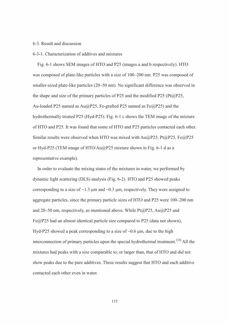
115
6-3. Result and discussion
6-3-1. Characterization of addtives and mixtures
Fig. 6-1 shows SEM images of HTO and P25 (images a and b respectively). HTO
was composed of plate-like particles with a size of 100–200 nm. P25 was composed of
smaller-sized plate-like particles (20–50 nm). No significant difference was observed in
the shape and size of the primary particles of P25 and the modified P25 (Pt@P25,
Au-loaded P25 named as Au@P25, Fe-grafted P25 named as Fe@P25) and the
hydrothermally treated P25 (Hyd-P25). Fig. 6-1 c shows the TEM image of the mixture
of HTO and P25. It was found that some of HTO and P25 particles contacted each other.
Similar results were observed when HTO was mixed with Au@P25, Pt@P25, Fe@P25
or Hyd-P25 (TEM image of HTO/Au@P25 mixture shown in Fig. 6-1 d as a
representative example).
In order to evaluate the mixing states of the mixtures in water, we performed by
dynamic light scattering (DLS) analysis (Fig. 6-2). HTO and P25 showed peaks
corresponding to a size of ~1.3 μm and ~0.3 μm, respectively. They were assigned to
aggregate particles, since the primary particle sizes of HTO and P25 were 100–200 nm
and 20–50 nm, respectively, as mentioned above. While Pt@P25, Au@P25 and
Fe@P25 had an almost identical particle size compared to P25 (data not shown),
Hyd-P25 showed a peak corresponding to a size of ~0.6 μm, due to the high
interconnection of primary particles upon the special hydrothermal treatment.[10] All the
mixtures had peaks with a size comparable to, or larger than, that of HTO and did not
show peaks due to the pure additives. These results suggest that HTO and each additive
contacted each other even in water.
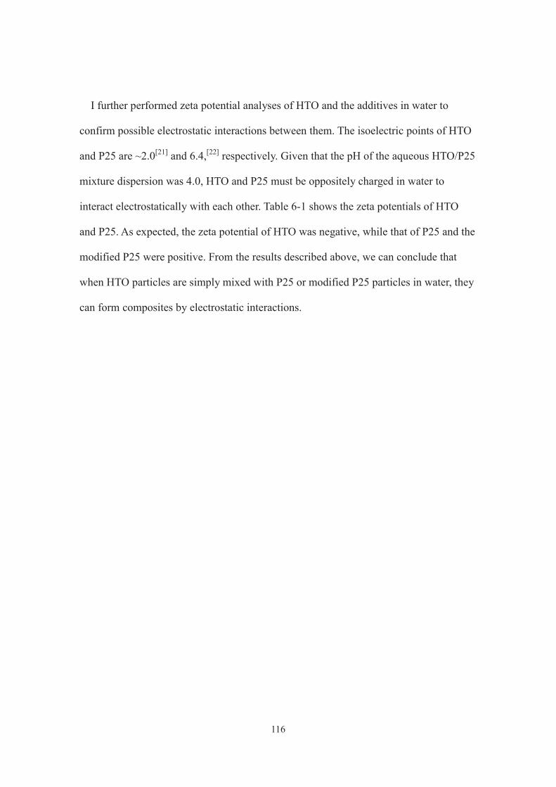
116
I further performed zeta potential analyses of HTO and the additives in water to
confirm possible electrostatic interactions between them. The isoelectric points of HTO
and P25 are ~2.0[21] and 6.4,[22] respectively. Given that the pH of the aqueous HTO/P25
mixture dispersion was 4.0, HTO and P25 must be oppositely charged in water to
interact electrostatically with each other. Table 6-1 shows the zeta potentials of HTO
and P25. As expected, the zeta potential of HTO was negative, while that of P25 and the
modified P25 were positive. From the results described above, we can conclude that
when HTO particles are simply mixed with P25 or modified P25 particles in water, they
can form composites by electrostatic interactions.
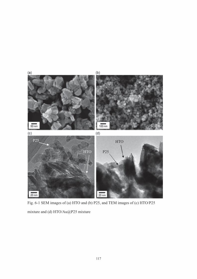
117
P25
HTO P25
HTO
Fig. 6-1 SEM images of (a) HTO and (b) P25, and TEM images of (c) HTO/P25
mixture and (d) HTO/Au@P25 mixture
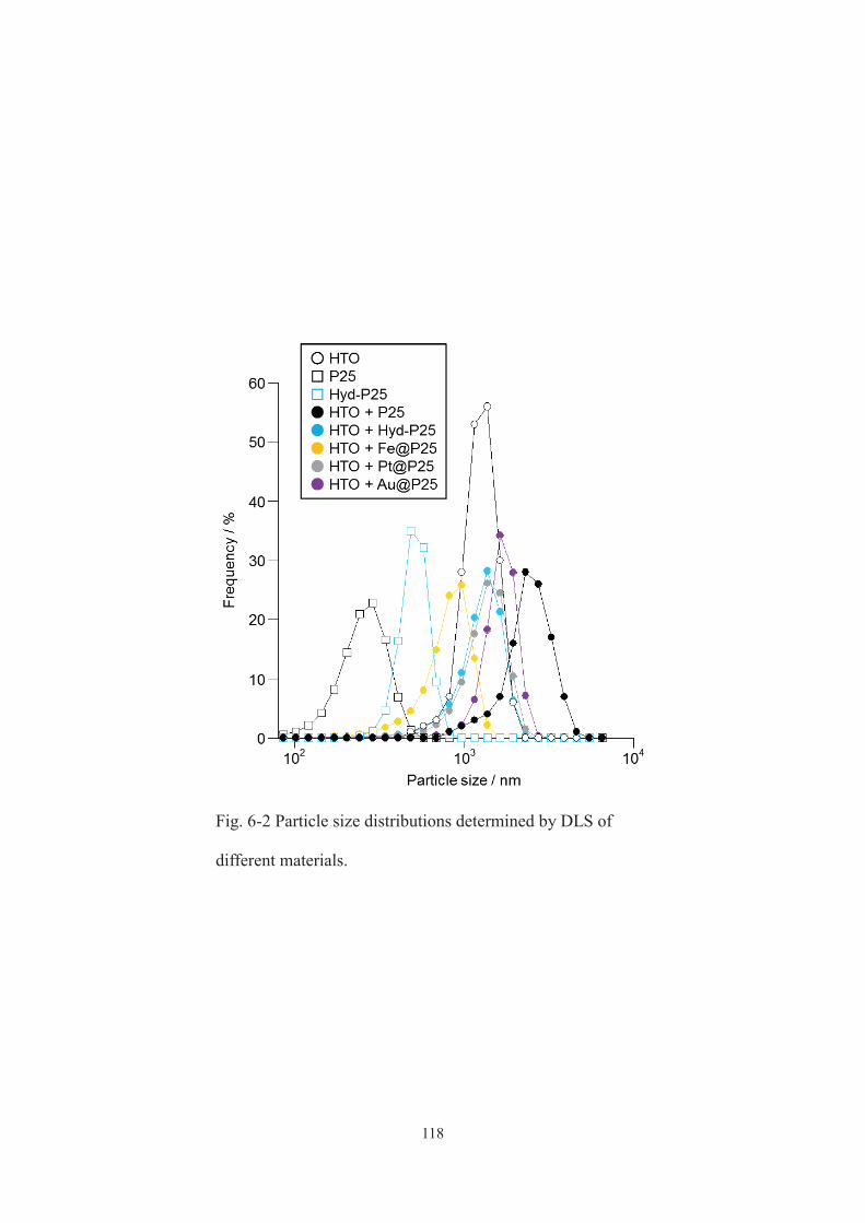
118
Fig. 6-2 Particle size distributions determined by DLS of
different materials.
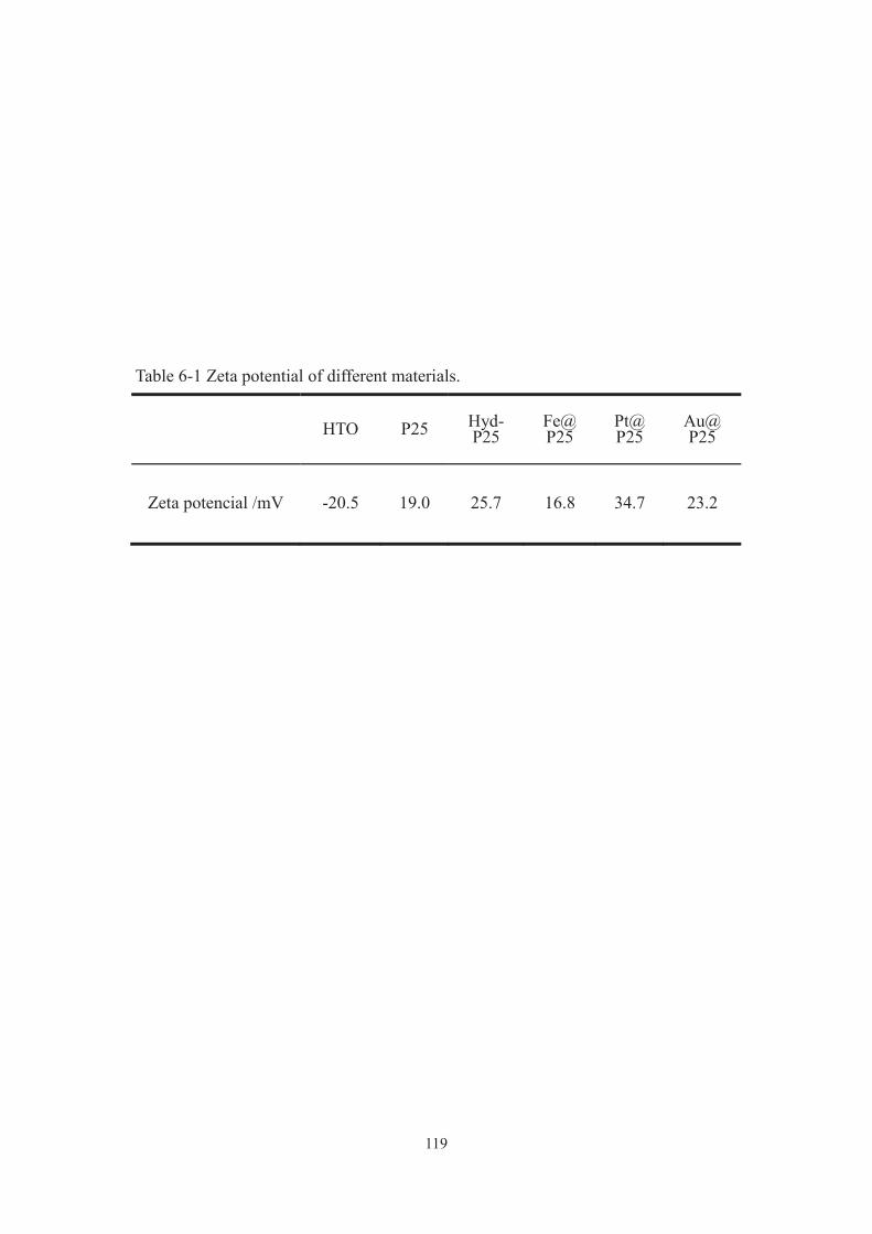
119
Table 6-1 Zeta potential of different materials.
HTO P25 Hyd- P25
Fe@ P25
Pt@ P25
Au@ P25
Zeta potencial /mV -20.5 19.0 25.7 16.8 34.7 23.2
120
6-3-2. Photocatalytic test
The photocatalytic performance of these mixtures was evaluated through the
oxidation of formic acid to CO2 in water under solar light irradiation (λ > 300 nm). In a
previous study, we optimized the mixing ratio of HTO and P25 particles (HTO/P25 = 13
mg/2 mg).[11] Thus, we used the same mixing ratio in this study. Fig. 6-3 summarizes the
results of the photocatalytic experiments. HTO showed no activity for this reaction.
However, it showed a greatly enhanced activity upon mixing with any additives and the
activity of the mixtures roughly depended on that of the additives (Fig. 6-4). The
HTO/Au@P25 mixture showed the best activity, which was 8- and 1.5-times higher
than that of P25 and the HTO/Pt@P25 mixture, respectively. The activity of
HTO/Au@P25 was comparable to that of pure Au@P25, using the same amount of
powder (15 mg), while the amount of Au contained in the HTO/Au@P25 mixed system
was only 0.27 wt.%, which was considerably smaller than that contained in the pure
Au@P25 system (2.0 wt.%).
Considering the electronic band structures of HTO and P25 (Fig. 6-5),[23,24] we
proposed that the enhanced photocatalytic activity of the HTO/P25 mixture (or the
HTO/Pt@P25 mixture) resulted from the transfer of photoexcited electrons from HTO
to P25 (or Pt@P25) and retardation of charge recombination.[11] To confirm this, I
investigated the possibility of opposite-direction charge transfer in the HTO/Au@P25
system. As shown in Fig. 6-3 (below dashed line), under the irradiation of > 450 nm
solar light, at which only Au@P25 was excited, the HTO/Au@P25 mixture and
Au@P25 showed almost identical activity when using the same amount of Au@P25 (2
mg). This indicates that the electron transfer from the excited Au@P25 to HTO did not
occur to enhance the activity of Au@P25.[25] Therefore, as proposed in the previous

121
study, the enhancedphotocatalytic activity of the mixture of HTO with P25, or the
modified P25, results from enhanced charge separation via electron transfer from HTO
to the additive. On the other hand, considering electric band structures of HTO and P25
(Fig. 6-5), transfer of photogenerated holes from Au@P25 to HTO upon UV excitation
is thermodynamically unfavorable.
It should be also noted that the HTO/Hyd-P25 mixture exhibited activity comparable
to that of HTO/Pt@P25 (Fig. 6-3). Hyd-P25 is composed of anatase and rutile
nanoparticles, which are much more interconnected than in P25, and thus exhibits
remarkably enhanced charge separation and photocatalytic efficiency.[10] Owing to its
high charge separation efficiency, Hyd-P25 was likely to be a good additive comparable
to Pt@P25, where the Pt co-catalyst effectively accumulates electrons. The modification
of Hyd-P25 with Pt or Au and the use of modified Hyd-P25 as additive to HTO are
worth investigating in the search for more effective photocatalytic systems.

122
Fig. 6-3 Photocatalytic activity of different materials.
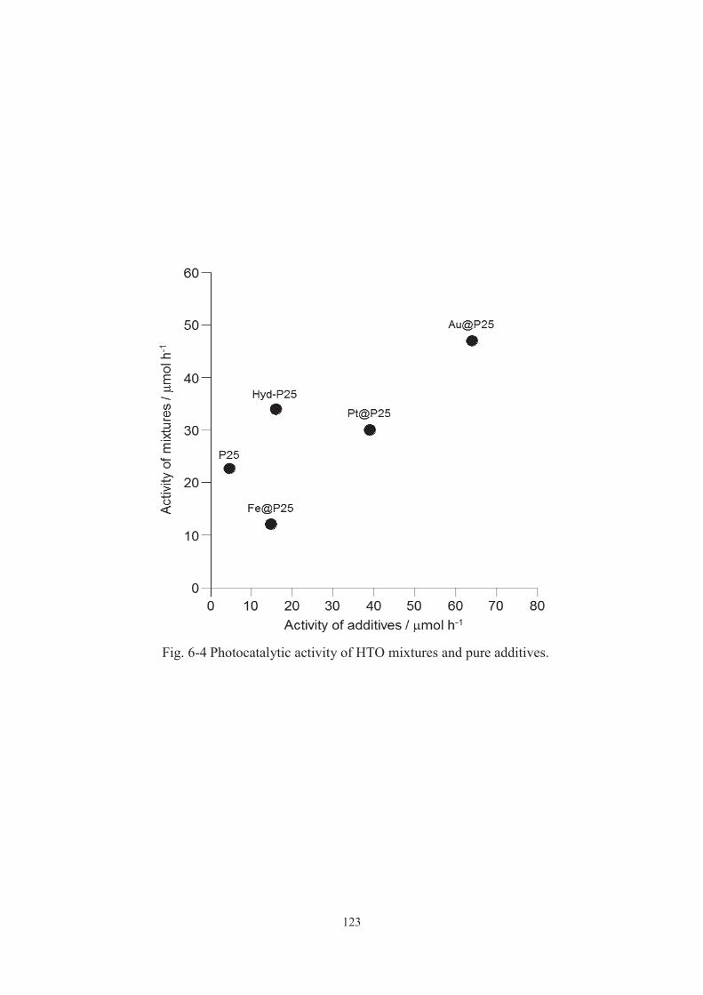
123
Fig. 6-4 Photocatalytic activity of HTO mixtures and pure additives.

124
Fig. 6-5 Electric band structures of HTO and P25.
125
6-4. Conclusion
I found the positive effects of particle-level mixing of a layered titanate (HTO) and a much
smaller amount (~10 wt.%) of various additives, including Pt or Au-loaded TiO2 (P25), on the
photocatalytic activity of the mixtures for the oxidation of formic acid in water under solar light
irradiation. Pure HTO scarcely showed any activity, but the mixtures showed remarkably
enhanced activity, roughly depending on the activity of the individual additives. I could
conclude that this enhancement resulted from electron transfer from the excited HTO to the
additive via their particle interfaces, enhancing charge separation and UV-induced
photocatalytic efficiency of HTO. The mixture of HTO with Au-loaded P25 showed the best
activity, which was 8 times higher than that of P25, a benchmark photocatalyst, and comparable
to that of pure Au-loaded P25 (Au loading of 2.0 wt.%), using the same amount of powder. I
thus attained largely enhanced activity despite the use of an unusually small amount (0.27 wt.%)
of the noble metal. Since a wide variety of advanced TiO2 materials, including those with
precious metal co-catalysts, are available, their use as additives in conventional photocatalytic
systems is underway in our laboratory.
126
6-5. References
[1] M. Anpo, Bull. Chem. Soc. Jpn., 2004, 77, 1427.
[2] A. Fujishima, X. Zhang and D. A. Tryk, Surf. Sci. Rep., 2008, 63, 515.
[3] A. Kudo and Y. Miseki, Chem. Soc. Rev., 2009, 38, 253.
[4] J. L. Vivero-Escoto, Y.-D. Chiang, K. C.-W. Wu and Y. Yamauchi, Sci. Technol. Adv.
Mater., 2012, 13, 13003.
[5] H. Tada, T. Kiyonaga and S. Naya, Chem. Soc. Rev., 2009, 38, 1849.
[6] T. Tatsuma, Bull. Chem. Soc. Jpn., 2013, 86, 1.
[7] H. Kominami, T. Matsuura, K. Iwai, B. Ohtani, S. Nishimoto and Y. Kera, Chem.
Lett., 1995, 693.
[8] F. Amano, O. O. Prieto-Mahaney, Y. Terada, T. Yasumoto, T. Shibayama and B.
Ohtani, Chem. Mater., 2009, 21, 2601.
[9] Z. Bian, T. Tachikawa and T. Majima, J. Phys. Chem. Lett., 2012, 3, 1422.
[10] Y. Ide, N. Inami, H. Hattori, K. Saito, M. Sohmiya, N. Tsunoji, K. Komaguchi, T.
Sano, Y. Bando, D. Golberg and Y. Sugahara, Angew. Chem. Int. Ed., 2016, 55, 3600.
[11] K. Saito, M. Kozeni, M. Sohmiya, K. Komaguchi, M. Ogawa, Y. Sugahara and Y.
Ide, Phys. Chem. Chem. Phys., 2016, 18, 30920.
[12] Y. I. Kim, S. Salim, M. J. Huq and T. E. Mallouk, J. Am. Chem. Soc., 1991, 113,
9561.
[13] J. L. Gunjakar, I. Y. Kim, J. M. Lee, Y. K. Jo and S. Hwang, J. Phys. Chem. C,
2014, 118, 3847.
[14] Y. Ide, M. Sadakane, T. Sano and M. Ogawa, J. Nanosci. Nanotechnol., 2014, 14,
2135.
[15] T. Okada, Y. Ide and M. Ogawa, Asian J. Chem., 2012, 7, 1980.
127
[16] M. Ogawa, M. Morita, S. Igarashi and S. Sato, J. Solid State Chem., 2013, 206, 9.
[17] T. Sasaki, F. Kooli, M. Iida, Y. Michiue, S. Takenouchi, Y. Yajima, F. Izumi, B. C.
Chakoumakos and M. Watanabe, Chem. Mater., 1998, 10, 4123.
[18] D. Tsukamoto, Y. Shiraishi,Y. Sugano, S. Ichikawa, S. Tanaka and T. Hirai, J. Am.
Chem. Soc., 2012, 134, 6309.
[19] H. Tada, Q. Jin, H. Nishijima, H. Yamamoto, M. Fujishima, S. Okuoka, T. Hattori,
Y. Sumida and H. Kobayashi, Angew. Chem. Int. Ed., 2011, 50, 3501.
[20] Y. Ide, H. Hattori, S. Ogo, M. Sadakane and T. Sano, Green Chem., 2012, 14,
1264.2
[21] S. Tsukahara, N. Soh and K. Kamada, J. Phys. Chem. C, 2012, 116, 19285.
[22] B. Ohtani, Y. Okugawa, S. Nishimoto and T. Kagiya, J. Phys. Chem., 1987, 91,
3550.
[23] N. Sakai, Y. Ebina, K. Takada and T. Sasaki, J. Am. Chem. Soc., 2004, 126, 5851.
[24] D. E. Scaife, Sol. Energy, 1980, 25, 41.
[25] Y. Ide, K. Nagao, K. Saito, K. Komaguchi, R. Fuji, A. Kogure, Y. Sugahara, Y.
Bando and D. Golberg, Phys. Chem. Chem. Phys., 2016, 18, 79.
128
Chapter 7
Microporous titanate nanofibers for highly efficient UV-protective transparent coating
7-1. Introduction
UV caused DNA damage, immune suppression and skin photoaging for people, and is
also responsible for the decomposition and degradation of organic compounds including
plastics, polymers, dyes, pigments, wood and paper that compose most of modern
commonly used articles and devices. Therefore, the protection against UV irradiation
damage is of a great interest for ordinary people, scientists and industries. Organic UV
absorbers, embedded in polymer coatings, have been extensively used to protect organic
materials against UV irradiation by transforming the absorbed radiation energy into the
less damaging thermal energy through photophysical processes. [1, 2] However, its
application has been limited because the polymer may be decomposed at the excited
state on absorbers under UV light irradiation. [3]
Due to its abundance, non-toxicity, high stabilities and UV absorbing property, titania
(and titanate) has been expected as the alternative to organic UV absorbers. However,
titania presents major drawbacks to be used as UV absorbers: i) it exhibits a high
UV-induced photocatalytic activity that can induce the photodegradation of organic
media in which they are embedded; ii) it possesses a considerably higher refractive
index than those of commodity polymer matrices, thus lowering the diffusion of visible
light to whiten the medium (that limits its usage in color sensible applications, such as
artwork protection and optical device). To overcome the drawbacks, development of
new titania-based UV-absorbers has been actively investigated under size control of
titania,[4] and its heteroelement doping[5] and hybridization with other inorganic

129
semiconductors (e.g. cerium dioxide).[6] New non-titania inorganic UV absorbers have
also been developed.[7, 8]
In this chapter I report the synthesis of a new titanate material, a microporous titanate
nanofiber, by a new route inspired by a zeolite synthesis method. Zeolite, which is an
aluminosilicate of a microporous structure widely used industrially, has been
conventionally synthesized by trial and error, but in recent years a relatively rational
method has been developed. This method called interzeolite conversion which
synthesizes target zeolites by hydrothermal treatment of starting zeolite [9-11]. In the
interzeolite conversion, a zeolite as a raw material is decomposed into aluminosilicate
species (nano parts) having locally ordered structure, and these nano parts are
reconstructed to obtain another zeolite having the framework similar to source material.
By changing the starting material zeolite and hydrothermal synthesis conditions,
expensive, high quality, or novel zeolite is being designed. Therefore, not only in the
case of aluminosilicate but also in other inorganic nanostructures, the same conversion
strategy can be applied to synthesis of porous structures with different composition and
physical properties.
In this study, therefore, I tried to synthesize a new microporous titanate by
hydrothermal treatment of potassium dititanate [12], one of layered titanates, as a source
material. By optimizing synthesis conditions, I succeeded in synthesis of titanium oxide
nanofibers having a plurality of one-dimensional pores. The newly developed material
effectively absorbs UV, hardly shows photocatalytic activity and exhibits an extremely
low refractive index, and then can be applied to a highly efficient UV protective
transparent coating.

130
7-2. Experiment
Reagents and materials
TiO2 (anatase), K2CO3 (99.9%), NH4F (97.0%), CaCl2 (>95%) and 2-propanol
(99.5%) were purchased from Wako Pure Chemical Industry. Tetrapropylammonium
(TPA) hydroxide (as a 40 wt% aqueous solution), crystal violet (CV, >95.0%) and
dodecylamine hydrochloride (>97.0%) were purchased from Tokyo Chemical Industry.
Cyclohexane (99.7%) and acetonitrile (99.8%) were purchased from Nacalai Tesque.
Rhodamine 101 and polycaprolactone (PCL) were obtained from Sigma-Aldrich. P25,
rutile (JRC-TIO-06) and synthetic saponite were supplied by Nippon Aerosil, Catalysis
Society of Japan and The Clay Science Society of Japan, respectively. TPA hydroxide
was used after the evaporation of the solvent to tune a molar ratio of TPA and H2O for
hydrothermal reactions. All the other reagents and materials were used as received.
Hydrothermal reactions
K2Ti2O5, prepared by a solid state reaction between K2CO3 and anatase according tothe
literature[12],was mixed with TPA hydroxide, water and NH4F at a molar ratio of
K2Ti2O5 : TPA : H2O : NH4F = 1 : 0.8 : 5 : 0.2 in an Teflon-lined stainless steel
autoclave, and the mixture was heated at 170 °C for a week. After the hydrothermal
treatment, the dried gel-like solidwaswashedwithwater and dried at 70 °C to give the
product and eluate. Control experiments were conducted without TPA hydroxide and/or
NH4F. P25 and K0.66Ti1.73Li0.27O4, which was prepared according to the literature[13],
were also hydrothermally treated under identical conditions.
131
Characterization
The crystal morphology was observed by scanning electron microscopy (SEM,
Hitachi S-4800) and elemental mapping of products was conducted by SEM and
energy-dispersive X-ray (EDX) analysis. High resolution transmission electron
microscopy (HRTEM) was performed with a JEOL JEM-3000F highresolution
transmission electron microscope equipped with an EDX analyser. X-ray diffraction
(XRD) patterns of the solid products were collected using a powder X-ray
diffractometer (Bruker D8 Advance) with graphite monochromatized Cu Ka radiation at
40 kV and 30 mA. N2 and Ar adsorption/desorption isotherms were obtained using a
Belsorp-max apparatus (Bel Japan). Prior to the adsorption measurements, the samples
were evacuated at 120 °C for 12 h. Infrared spectra were recorded using a FT-IR
spectrometer (Nicolet 6700) with a resolution of 4 cm -1. The sample was pressed into a
self-supporting thin wafer, and then placed into a quartz cell equipped with CaF2
windows. Prior to the measurements, the sample was evacuatedat 200 °C for 3 h.
Thermogravimetric-differential thermal analysis (TG-DTA) curves were collected using
a SSC/5200 apparatus (Seiko Instruments). The sample was heated from room
temperature to 800 °C in an air fow (50 mL min -1) at a rate of 10 °C min -1. Inductively
coupled plasma atomic emission spectroscopy (ICP-AES) was performed on a SPS
7700 plasma spectrometer (Seiko Instruments). Ultraviolet-visible (UV-vis) spectra
were recorded with a JASCO V-579 UV/Vis/NIR spectrophotometer. X-ray
photoelectron spectroscopy (XPS) was performed with a Kratos ESCA-3400 electron
spectrometer, where the binding energies were calibrated using the O 1s peak. The
electrospray ionization (ESI) mass spectrum was recorded on a LCMS-8040 liquid
132
chromatograph mass spectrometer (Shimadzu) in the negative ion mode at a desolvation
temperature of 200 °C.
Ion exchange
50 and 5 mg of MPTNF powders were mixed with an aqueous solution containing
CaCl2 (40 mL, 0.06-60 mmol L-1) and CV (200 mL, 0.000875-0.0875 mmol L-1),
respectively, and the mixtures were stirred at room temperature for 3 days. The products
were separated from the mixtures by centrifugation (3500 rpm, 15 min). The amounts of
the adsorbed/desorbed Ca/K ions and the adsorbed CV ions were determined on the
basis of ICP-AES and UV-vis spectroscopy, respectively, of the supernatants. For
dodecylammonium adsorption, MPTNF (200 mg) was mixed with an aqueous solution
containing dodecylammonium hydrochloride (100 mL, 19.4 mmol L-1), and the mixture
was stirred at room temperature for 6 h. The product was separated from the mixtures
by centrifugation, and the amounts of the adsorbed dodecylammonium ions and the
desorbed K ions were determined on the basis of TG curve of the recovered solid and
ICP-AES of the supernatant, respectively.
Photocatalysis
Photocatalytic conversions were carried out by photoirradiation with solar simulator
(San-Ei Electric Co., Ltd) to a mixture of catalyst (60 mg), O2-saturated acetonitrile
(18 mL) solution of CH (2 mL) in a stainless-made closed container equipped with
Pyrex glass (75 mL) under controlled atmosphere at 42 °C, with shaking (3-24 h). After
analyzing gas phase, the irradiation was started. The container was placed by ca. 30 cm
away from the light source to irradiate 1 solar (1000 W m−2)-power light to the mixture.

133
After the reaction, the gas-phase product was analyzed by GC-TCD (Shimazu GC-8A).
The solution was mixed with naphthalene (as internal standard) and then recovered by
filtration, and the resulting supernatant was analyzed by GC-FID (Shimazu GC-2014).
The oxidation of 2-propanol in water was conducted in a way similar to that conducted
for cyclohexane oxidation.
Preparation and evaluation of UV protective coatings.
Rhodamine 101 film was prepared by casting a portion (2 mL) of a mixture of the
dye (10.2 mol L-1) and synthetic saponite (5.0 g L-1) in an aqueous ethanol (30 mL, 1/1
in v/v) onto a glass substrate (28 mm-width and 48 mm-length) followed by evaporation
of the solvent. A solution of PCL (200 mg) in chloroform (10 mL) was mixed with
MPTNF or P25 (20 mg for each sample) and a portion (1.0 mL) of the mixture was
casted onto the Rhodamine 101 film. After the evaporation of the solvent, the coated
film was irradiated by 1000 W m-2 power solar simulator (λ > 300 nm) at room
temperature. Uncoated Rhodamine 101 film was also irradiated for comparison. The
cast film of only MPTNF, P25 or K2Ti2O5 embedded in PCL was also prepared on a
quartz glass substrate to evaluate the transparency of the coating itself.

134
7-3. Results and discussion
7-3-1. Characterization of products
Potassium dititanate (named as K2Ti2O5) has a plate-like morphology with a lateral
size of a few μm and a thickness up to several hundreds of nm (Fig. 7-1 a and b) and is
composed of corrugated layers that are comprised of a distorted TiO5 trigonal bipyramid
and the interlayer K ions,[14] giving a basal spacing (multilayer repeat distance) of 0.64
nm (Fig. 7-2 a). When the layered titanate was hydrothermally treated under an alkali
condition in the presence of TPA hydroxide and NH4F, which are often used in
interzeolite conversion as a mineralizer and/or a structure-directing agent and a
mineralizer, respectively, a product whose morphology and structure were different
from those of K2Ti2O5 was obtained. The product had a fibrous morphology with a
diameter up to 10 nm and a length up to several hundreds of nm (so called “nanofiber”)
as can be seen in the SEM image and HRTEM image (Fig. 7-1 c and d), showed a XRD
pattern almost completely different from that of the starting K2Ti2O5 (Fig. 7-2 a) and
exhibited abrupt N2 uptake at lower partial pressure, which is indicative of the presence
of micropores (a pore diameter < 2 nm) or microchannels, in the N2
adsorption/desorption isotherms (Fig. 7-2 b). Careful HRTEM observations revealed
that neither nanotube-like particles nor small platy particles like K2Ti2O5 fragments
observed in Fig. 7-1 a and b were not contained in the product at all, suggesting again
that the product is microporous nanofibers derived from K2Ti2O5.
EDX spectroscopy revealed the presence of O, K and Ti, and the absence of F in
MPTNF (Fig. 7-1 e), indicating that F was not incorporated in the product, or NH4F
acted as a mineralizer in the formation of MPTNF (this point will be described in detail
below). I could not rule out the possibility of the occurrence of the only trace amount of

135
F in MPTNF only from the EDX analysis; on the other hand, it is known that titania and
titanate require substantial amounts of the incorporated F to slightly decrease the
refractive indices[15] and then the amount of the incorporated F is negligible judging
from the extremely low refractive index of MPTNF described below. The ICP-AES of
the dissolved MPTNF determined the Ti and K contents (Ti, 42.1 wt%; K, 12.1 wt%).
The TG-DTA curves of MPTNF did not show the weight loss due to the oxidative
decomposition of TPA, confirming that TPA was not incorporated in the product;
therefore, TPA hydroxide acted as a mineralizer rather than a structure directing agent
(this point will be also described below). The TG-DTA curves also showed the weight
loss (ca. 2.3 wt%) ascribable to the dehydration and condensation of the surface OH
groups in a temperature range from 200 to 800 ºC. The infrared spectrum of MPTNF
shown in Fig. 7-2 c confirmed the presence of isolated Ti-OH groups and
hydrogen-bonded Ti-OH groups (peaks at 3721 and 3652 cm-1, respectively). On the
basis of Ti, K and OH contents, the chemical formula of MPTNF was calculated to be
H0.65K0.75Ti2.15O5 (H exists as OH or partially H2O; which will be described below).
I investigated the structure of MPTNF in more detail. When treated with an aqueous
solution containing Ca ions, MPTNF adsorbed Ca ions accompanied by the desorption
of K ions. As shown in Fig. 7-2 d, the adsorption isotherm revealed the H-type
adsorption according to the Giles classification,[16] which indicates strong interactions
between MPTNF and Ca, and Ca adsorption capacity of ~ 2.3 mmol g-1, which was
comparable to the cation exchange capacity (1.75 mmol g-1 ) of MPTNF for divalent
cations predicted on the basis of the K content. These results indicate that K ions are
located on the surfaces of the micropores or microchannels as exchangeable cations. A
part of protons of the surface Ti-OH groups is also cationexchangeable, judging from

136
the fact that MPTNF could adsorb Ca ions more than the predicted cation exchange
capacity. On the other hand, the adsorption of a cationic organic dye, crystal violet (CV;
Fig. 7-2 d inset) with a molecular size of 1.4 × 1.4 ×0.4 nm3, from water on MPTNF
was also the H-Type; however CV adsorbed considerably less effectively on MPTNF
than Ca (Fig. 7-2 d), implying that CV could not penetrate effectively along a nanofiber
axial direction due to diffusion limitation. It should be noted here that the XRD pattern
of MPTNF did not change significantly (e.g. the diffraction peak corresponding to the d
value of 0.83 nm did not shift to a lower 2θ region) after the cation exchange reactions
(similar phenomenon was observed when K ions were almost quantitatively exchanged
with dodecylammonium ions), supporting that MPTNF does not have a layered
structure.[17] Horwarth-Kawazoe analysis,[18] which had successfully evaluated the
microchannels (so called tunnels” with a cross-section dimension of about 1.1 × 0.4
nm2 ) of sepiolite that is a microfibrous silicate,[19] was applied to the treatment of the
adsorption isotherms of Ar on MPTNF and the CV-exchanged MPTNF. From the
analysis (Fig. 7-2 b inset), MPTNF possessed a pore size distribution showing an
effective pore diameter of ca. 0.5 nm and adsorbed a significantly smaller amount of Ar
atoms after cation exchange with CV ions, which was explained by the fact that CV
molecules inside (mainly in the vicinity of the particle outer surface of) MPTNF
prevented the entrance of Ar atoms.[19] Such significant decrease of Ar uptake must not
be observed if MPTNF has randomly oriented micropores or microchannels
perpendicular to or across a nanofiber axial direction and similar phenomena have been
observed for sepiolite[19] and zeolites with threedimensional interconnecting
microchannels.[20,21] Furthermore, as confirmed by the appearance of broad absorption
at 3600- 3000 cm-1 in the infrared spectrum measured after evacuation at 200 ºC (Fig.
137
7-2 c), significant amount of H2O molecules adsorbed inside MPTNF, not but on the
particle outer surface (thus a part of the surface OH groups are H2O) and such
phenomena have also been reported for sepiolite and zeolites. From the all results and
facts described above, I deduce that MPTNF has one-dimensional microchannels rather
than micropores. From the high micro pore volume up to 0.08 cm3 g-1 (see below), that
is comparable to that of sepiolite,[19] MPTNF presumably has a number of
microchannels in a particle like sepiolite or TON-type zeolites. The expanded HRTEM
image presented in Fig. 7-1 d inset may show the edge of a MPTNF particle.
Besides its unique microstructure, MPTNF possessed i) a chemical stability toward
water (acidic and basic solutions) and organic solvents, ii) an extraordinarily high cation
exchange capacity (4.6 meq g-1 = 2 × 2.3 mmol g-1 for divalent cations) like a layered
titanate, H2Ti2O5 , which is one of the most highcapacity (5.0 meq g-1) cation
exchangers among known materials but unstable in water[22] and iii) a fibrous
morphology; therefore, it can be used as molecular sieve-like adsorbents, especially in
chromatographic separations,[23] as well as UV absorbers.
I discussed the formation mechanism of MPTNF. After the hydrothermal reaction
between K2Ti2O5, TPA hydroxide, NH4F and water, only dried gel-like product was
recovered, and the product was washed with water to obtain MPTNF with a 76 % of
yield on the basis of Ti content. On the other hand, the transparent eluate with water,
which must contain 24 % of the added Ti, was also obtained. I thus thought that the
eluate contained remnants of titania species (possibly “titania nanoparts”) which
assembled into MPTNF. In the UV-vis spectrum of the eluate, a sharp absorption peak
centered at 270 nm, which was not appeared in the UV-vis spectrum of MPTNF, was
observed (Fig. 7-2 e). Zeolites or mesoporous silicas having isolated tetrahedral Ti
138
species (highly dispersed titania species) show absorption at 220 nm in the UV-vis
spectra.[24] While, in the UV-vis spectra for colloidal suspensions of titanate nanosheets
derived from the exfoliation (delamination) of layered titanates, a well-developed
absorption peak centered around 270 nm is often observed, which is explained by the
presence of nanosheets with molecular-level thickness.[25,26] In the SEM image of the
dried eluate, neither nanosheet-like particles derived from K2Ti2O5 nor their ensembles
were observed at all (only KOH particles with a size up to a few hundreds of nm were
observed, although the corresponding SEM-EDX spectrum confirmed the presence of Ti,
K and O). Also, in the XRD pattern of MPTNF, the (020) peak due to the diffraction
within the titanate layers of K2Ti2O5 was still observed (Fig. 7-2 a). XPS revealed that
MPTNF had unique fivecoordinated Ti atoms like the starting K2Ti2O5[8] although most
titania and titanate, such as anatase and rutile (main components of a commercially
available TiO2, P25), had sixcoordinated ones (Fig. 7-2 f). Furthermore, the ESI-MS
spectrometry, which had been applied to investigate speciation in silica and silicate
solutions,[27,28] of the eluate showed the presence of a multitude of species up to
approximately 400 Da (data not shown). Therefore, I thought that Ti species in the
eluate were not Ti atoms derived from the complete dissolution of K2Ti2O5, but “titania
nanoparts” composed of TiO5 trigonal bipyramid units (Fig. 7-2 a, inset), whose
molecular weight is much smaller than that of the exfoliated K2Ti2O5 single-layer
nanosheet.
To understand the role of TPA and NH4F in the formation of MPTNF, control
hydrothermal reactions with or without the two compounds were conducted (Fig. 7-3).
When neither TPA hydroxide nor NH4F were added, split plate-like particles and
bundled nanofibrous particles were predominantly obtained (Fig. 7-3 a) and they

139
possessed a poor crystallinity (Fig. 7-3 b) and low mesopore (inter-particle pore) and
micropore (intra-particle pore) volumes (Fig. 7-3 c). By adding either TPA or NH4F,
well defined nanofibrous products were obtained and they had a higher crystallinity
than the product obtained in the absence of TPA and NH4F; while, NH4F gave a higher
micropore volume product than did TPA. The addition of both TPA and NH4F gave the
best product (MPTNF) in terms of crystallinity and micropore volume, although the
mesopore volume of MPTNF was similar to those for products obtained in the presence
of TPA or NH4F. From these results, both TPA and NH4F promoted the decomposition
of K2Ti2O5 into titnia nanoparts and NH4F acted as a mineralizer to promote the
assembling of the obtained titania nanoparts into MPTNF more effectively than TPA
did.
It is well-known that TiO2 (anatase, rutile, brookite or amorphous phase) can
transform into titania nanotube under alkaline hydrothermal conditions (without any
organic ammoniums and fluorides), and it is generally agreed that titania nanotubes
form through the dissolution and subsequent recrystallization of TiO2 particulate
precursor into single- or multi-walled nanosheets, which then scroll or wrap into
nanotubes.[29] Under the similar hydrothermal conditions at higher temperature,
non-porous titania nanofibers (or nanorods) have also been obtained.[29] Furthermore, it
has been reported that K2Ti2O5 transforms into anatase (or TiO2 (B)) with a
microfibrous morphology when treated with acid (cationexchanged with proton) and
then heated.[30-32] The XRD pattern of the present MPTNF was not in agreement with
those of such conventional titania and titanate materials. These facts support my
hypothesis that MPTNF forms through a new route involving the formation and
assembling of titania nanoparts.
140
To further demonstrate our hypothesis, other inorganics were hydrothermally treated
under the identical condition. After the hydrothermal treatment of P25 (composed of
anatase, rutile and amorphous titania[33]), the intensity of the XRD diffraction peaks due
to anatase and rutile increased (Fig. 7-4 a) and smaller particles deposited on the
original P25 particles (Fig. 7-4 b), which were explained by the fact that amorphous
titania converted into anatase and rutile. On the other hand, after the hydrothermal
treatment of a layered titanate with lepidocrocite structure, K0.66Ti1.73Li0.27O4 (Fig. 7-4 a
inset),[34] anatase with a particle size less than 100 nm deposited on platy particles of the
original titanate (Fig. 7-4 a and b). This resulted from that amorphous phase or lower
crystallinity-K0.66Ti1.73Li0.27O4 converted into anatase. Furthermore, a layered niobate,
K4Nb6O17·3H2O,[35] converted into a product whose structure and morphology were
different from those of the starting niobates, nanotubular niobate (data not shown).
Therefore, as reported for interzeolite conversion,[36] the local structures of starting
materials is a key for the present hydrothermal conversion; it is difficult for anatase,
rutile and K0.66Ti1.73Li0.27O4, in which TiO6 octahedra are strongly connected each other
by both point and edge shearing (Fig. 7-4 a inset), to decompose into nanoparts under
the present hydrothermal condition, on the other hand, K2Ti2O5, amorphous titania (or
lower crystallinity-K0.66Ti1.73Li0.27O4) and K4Nb6O17·3H2O possesses weakly connected
TiO5 trigonal bipyramids, TiO6 and NbO6 octahedra, respectively, each other only by
point shearing and thereby can easily decompose into nanoparts. A wide variety of
crystalline inorganics with different local structures is available and various
hydrothermal conditions (higher temperature, stronger bases, structure directing agents,
and so on) can be used; therefore, the presently proposed interzeolite

141
conversion-inspired method seems versatile to design metal oxides nanostructured
materials.
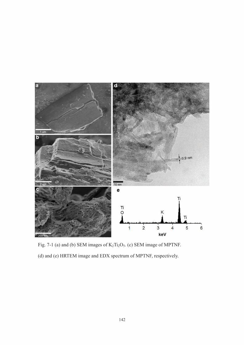
142
Fig. 7-1 (a) and (b) SEM images of K2Ti2O5. (c) SEM image of MPTNF.
(d) and (e) HRTEM image and EDX spectrum of MPTNF, respectively.

143
Fig. 7-2 (a) XRD patterns of K2Ti2O5 and MPTNF. Inset shows the crystal structure of
K2Ti2O5. (b) N2 adsorption (open circles)/desorption (filled circles) isotherms of
K2Ti2O5 and MPTNF. Inset shows the pore size distribution of MPTNF (top) and the
CV-exchanged MPTNF (bottom) determined by adsorption isotherms of Ar. (c) IR
spectra of K2Ti2O5 and MPTNF. (d) Adsorption isotherms of Ca (left) and CV (right)
from water on MPTNF. Horizontal dashed lines denote the cation exchange capacity of
MPTNF based on the K content for divalent and monovalent cations, respectively. Inset
shows the structure of CV. (e) Diffused reflectance UV-vis spectrum of K2Ti2O5,
MPTNF and P25. UV-vis absorption spectrum of an eluate obtained during MPTNF
synthesis is also shown. (f) Ti 2p XPS results of K2Ti2O5, MPTNF and P25.
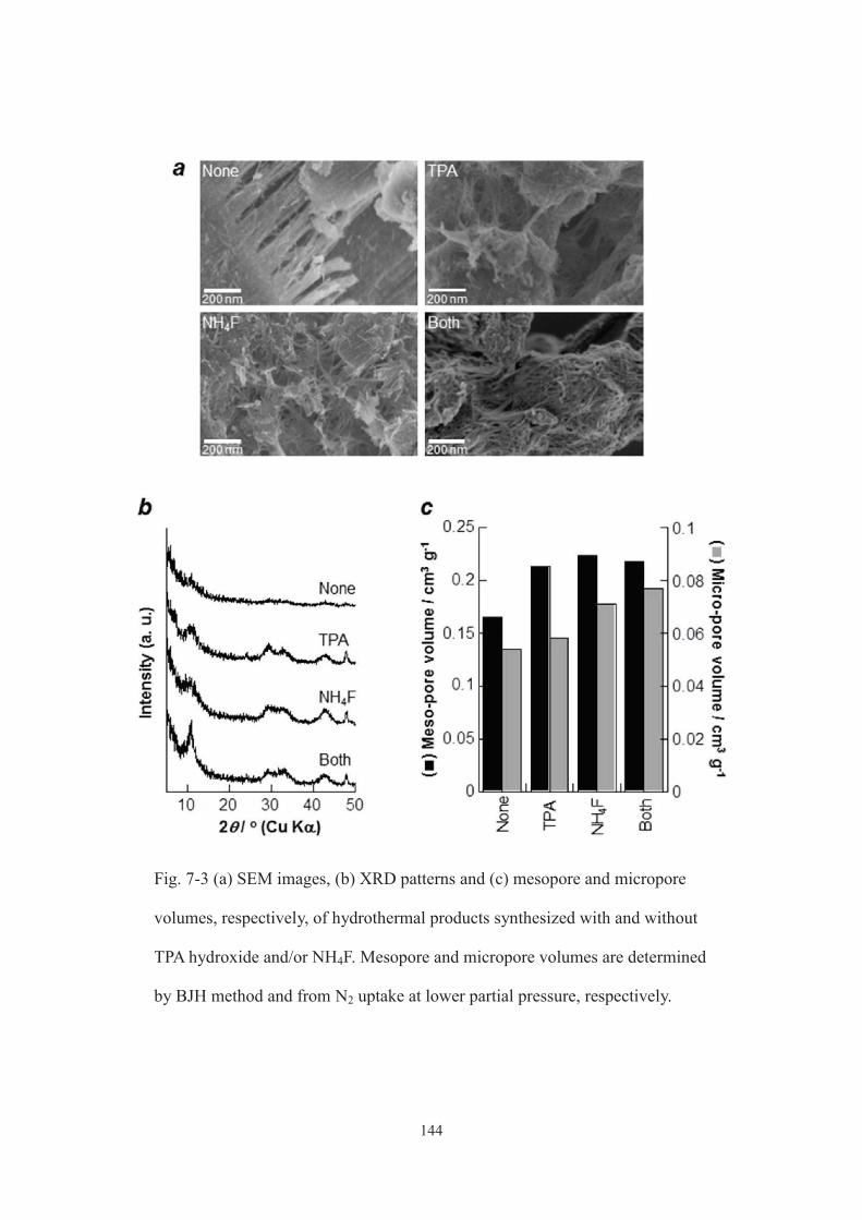
144
Fig. 7-3 (a) SEM images, (b) XRD patterns and (c) mesopore and micropore
volumes, respectively, of hydrothermal products synthesized with and without
TPA hydroxide and/or NH4F. Mesopore and micropore volumes are determined
by BJH method and from N2 uptake at lower partial pressure, respectively.
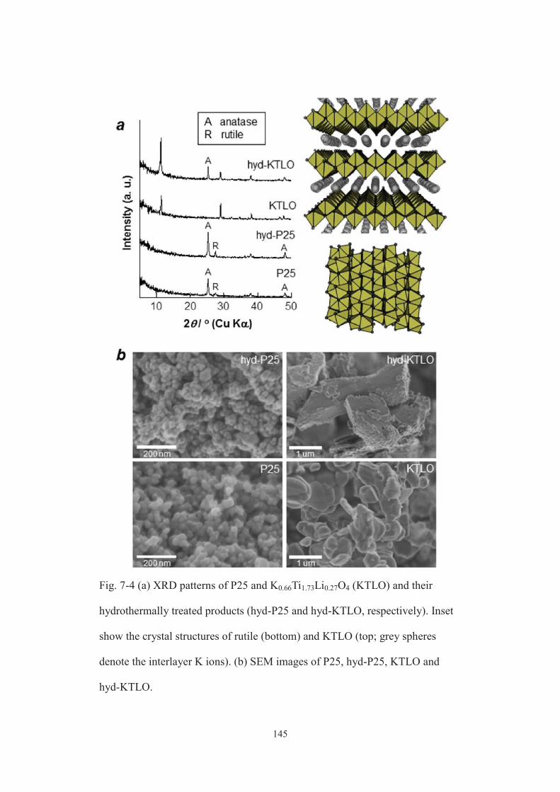
145
Fig. 7-4 (a) XRD patterns of P25 and K0.66Ti1.73Li0.27O4 (KTLO) and their
hydrothermally treated products (hyd-P25 and hyd-KTLO, respectively). Inset
show the crystal structures of rutile (bottom) and KTLO (top; grey spheres
denote the interlayer K ions). (b) SEM images of P25, hyd-P25, KTLO and
hyd-KTLO.
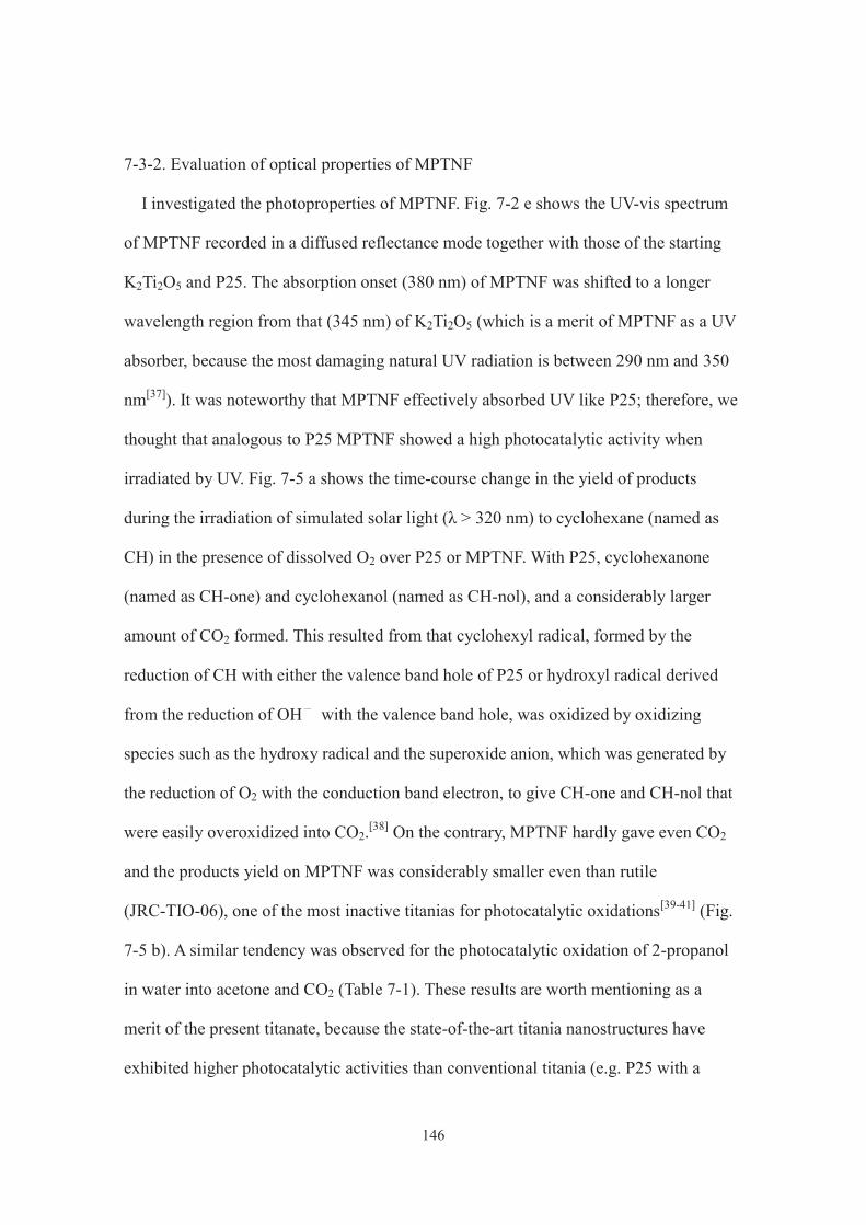
146
7-3-2. Evaluation of optical properties of MPTNF
I investigated the photoproperties of MPTNF. Fig. 7-2 e shows the UV-vis spectrum
of MPTNF recorded in a diffused reflectance mode together with those of the starting
K2Ti2O5 and P25. The absorption onset (380 nm) of MPTNF was shifted to a longer
wavelength region from that (345 nm) of K2Ti2O5 (which is a merit of MPTNF as a UV
absorber, because the most damaging natural UV radiation is between 290 nm and 350
nm[37]). It was noteworthy that MPTNF effectively absorbed UV like P25; therefore, we
thought that analogous to P25 MPTNF showed a high photocatalytic activity when
irradiated by UV. Fig. 7-5 a shows the time-course change in the yield of products
during the irradiation of simulated solar light (λ > 320 nm) to cyclohexane (named as
CH) in the presence of dissolved O2 over P25 or MPTNF. With P25, cyclohexanone
(named as CH-one) and cyclohexanol (named as CH-nol), and a considerably larger
amount of CO2 formed. This resulted from that cyclohexyl radical, formed by the
reduction of CH with either the valence band hole of P25 or hydroxyl radical derived
from the reduction of OH with the valence band hole, was oxidized by oxidizing
species such as the hydroxy radical and the superoxide anion, which was generated by
the reduction of O2 with the conduction band electron, to give CH-one and CH-nol that
were easily overoxidized into CO2.[38] On the contrary, MPTNF hardly gave even CO2
and the products yield on MPTNF was considerably smaller even than rutile
(JRC-TIO-06), one of the most inactive titanias for photocatalytic oxidations[39-41] (Fig.
7-5 b). A similar tendency was observed for the photocatalytic oxidation of 2-propanol
in water into acetone and CO2 (Table 7-1). These results are worth mentioning as a
merit of the present titanate, because the state-of-the-art titania nanostructures have
exhibited higher photocatalytic activities than conventional titania (e.g. P25 with a
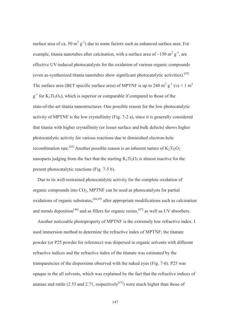
147
surface area of ca. 50 m2 g-1) due to some factors such as enhanced surface area. For
example, titania nanotubes after calcination, with a surface area of ~150 m2 g-1, are
effective UV-induced photocatalysts for the oxidation of various organic compounds
(even as-synthesized titania nanotubes show significant photocatalytic activities).[42]
The surface area (BET specific surface area) of MPTNF is up to 240 m2 g-1 (vs < 1 m2
g-1 for K2Ti2O5), which is superior or comparable if compared to those of the
state-of-the-art titania nanostructures. One possible reason for the low photocatalytic
activity of MPTNF is the low crystallinity (Fig. 7-2 a), since it is generally considered
that titania with higher crystallinity (or lesser surface and bulk defects) shows higher
photocatalytic activity for various reactions due to diminished electron-hole
recombination rate.[43] Another possible reason is an inherent nature of K2Ti2O5
nanoparts judging from the fact that the starting K2Ti2O5 is almost inactive for the
present photocatalytic reactions (Fig. 7-5 b).
Due to its well-restrained photocatalytic activity for the complete oxidation of
organic compounds into CO2, MPTNF can be used as photocatalysts for partial
oxidations of organic substrates,[44,45] after appropriate modifications such as calcination
and metals deposition[46] and as fillers for organic resins,[47] as well as UV absorbers.
Another noticeable photoproperty of MPTNF is the extremely low refractive index. I
used immersion method to determine the refractive index of MPTNF; the titanate
powder (or P25 powder for reference) was dispersed in organic solvents with different
refractive indices and the refractive index of the titanate was estimated by the
transparencies of the dispersions observed with the naked eyes (Fig. 7-6). P25 was
opaque in the all solvents, which was explained by the fact that the refractive indices of
anatase and rutile (2.53 and 2.71, respectively[47]) were much higher than those of
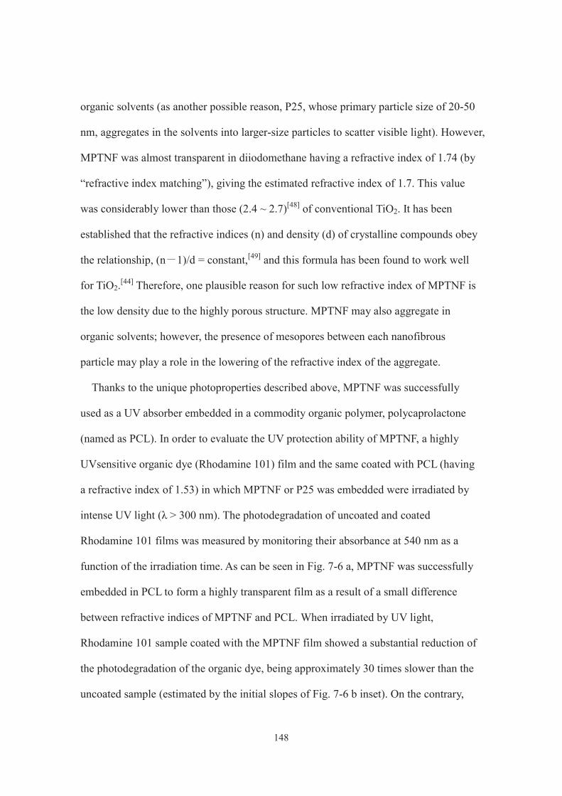
148
organic solvents (as another possible reason, P25, whose primary particle size of 20-50
nm, aggregates in the solvents into larger-size particles to scatter visible light). However,
MPTNF was almost transparent in diiodomethane having a refractive index of 1.74 (by
“refractive index matching”), giving the estimated refractive index of 1.7. This value
was considerably lower than those (2.4 ~ 2.7)[48] of conventional TiO2. It has been
established that the refractive indices (n) and density (d) of crystalline compounds obey
the relationship, (n 1)/d = constant,[49] and this formula has been found to work well
for TiO2.[44] Therefore, one plausible reason for such low refractive index of MPTNF is
the low density due to the highly porous structure. MPTNF may also aggregate in
organic solvents; however, the presence of mesopores between each nanofibrous
particle may play a role in the lowering of the refractive index of the aggregate.
Thanks to the unique photoproperties described above, MPTNF was successfully
used as a UV absorber embedded in a commodity organic polymer, polycaprolactone
(named as PCL). In order to evaluate the UV protection ability of MPTNF, a highly
UVsensitive organic dye (Rhodamine 101) film and the same coated with PCL (having
a refractive index of 1.53) in which MPTNF or P25 was embedded were irradiated by
intense UV light (λ > 300 nm). The photodegradation of uncoated and coated
Rhodamine 101 films was measured by monitoring their absorbance at 540 nm as a
function of the irradiation time. As can be seen in Fig. 7-6 a, MPTNF was successfully
embedded in PCL to form a highly transparent film as a result of a small difference
between refractive indices of MPTNF and PCL. When irradiated by UV light,
Rhodamine 101 sample coated with the MPTNF film showed a substantial reduction of
the photodegradation of the organic dye, being approximately 30 times slower than the
uncoated sample (estimated by the initial slopes of Fig. 7-6 b inset). On the contrary,
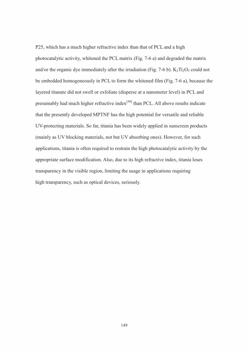
149
P25, which has a much higher refractive index than that of PCL and a high
photocatalytic activity, whitened the PCL matrix (Fig. 7-6 a) and degraded the matrix
and/or the organic dye immediately after the irradiation (Fig. 7-6 b). K2Ti2O5 could not
be embedded homogeneously in PCL to form the whitened film (Fig. 7-6 a), because the
layered titanate did not swell or exfoliate (disperse at a nanometer level) in PCL and
presumably had much higher refractive index[50] than PCL. All above results indicate
that the presently developed MPTNF has the high potential for versatile and reliable
UV-protecting materials. So far, titania has been widely applied in sunscreen products
(mainly as UV blocking materials, not but UV absorbing ones). However, for such
applications, titania is often required to restrain the high photocatalytic activity by the
appropriate surface modification. Also, due to its high refractive index, titania loses
transparency in the visible region, limiting the usage in applications requiring
high transparency, such as optical devices, seriously.
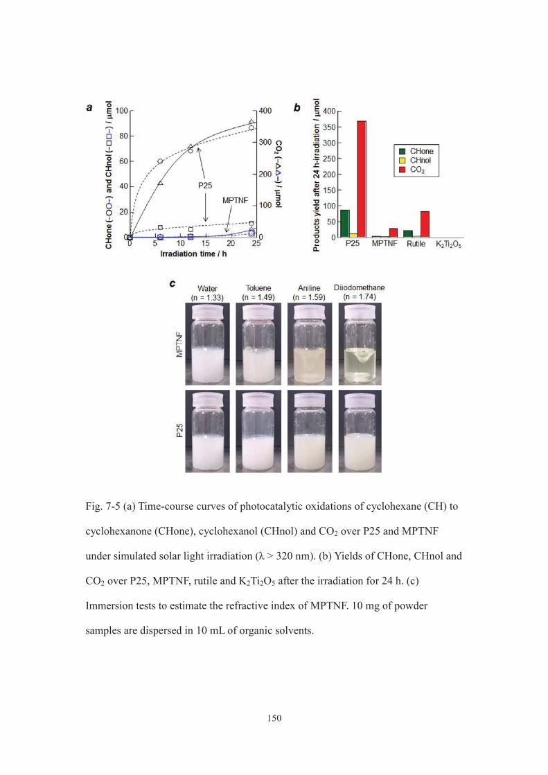
150
Fig. 7-5 (a) Time-course curves of photocatalytic oxidations of cyclohexane (CH) to
cyclohexanone (CHone), cyclohexanol (CHnol) and CO2 over P25 and MPTNF
under simulated solar light irradiation (λ > 320 nm). (b) Yields of CHone, CHnol and
CO2 over P25, MPTNF, rutile and K2Ti2O5 after the irradiation for 24 h. (c)
Immersion tests to estimate the refractive index of MPTNF. 10 mg of powder
samples are dispersed in 10 mL of organic solvents.
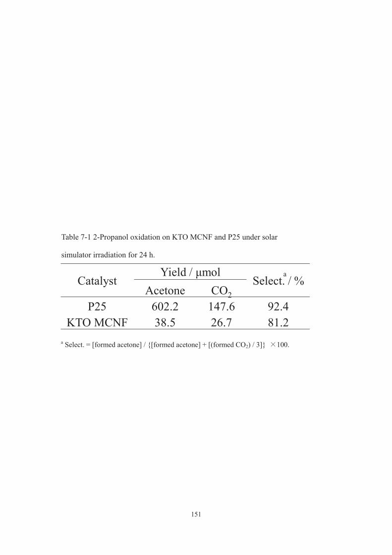
151
CatalystYield / μmol
Select. / %Acetone CO2
P25 602.2 147.6 92.4 KTO MCNF 38.5 26.7 81.2
Table 7-1 2-Propanol oxidation on KTO MCNF and P25 under solar
simulator irradiation for 24 h.
a Select. = [formed acetone] / {[formed acetone] + [(formed CO2) / 3]} 100.
a

152
Fig. 7-6(a) UV-vis transmittance spectra of films of PCL and those containing
MPTNF, P25 or K2Ti2O5. (b) Pictures showing Rhodamine 101 films uncoated and
coated with MPTNF and P25 embedded in PCL before and after UV irradiation (λ >
300 nm). Inset shows time-course curves of the UV-induced photodegradation of the
uncoated and coated Rhodamine 101 films.

153
7-4. Conclusion
I have reported that a layered titanate K2Ti2O5 successfully converts into a new
titanate nanostructured material, a microporous titanate nanofiber having possible
onedimensional multi-microchannels, via interzeolite conversion method. [51] The new
material exhibited a well-restrained photocatalytic activity and extremely low refractive
index, which allowed us to create a highly efficient UV protective transparent coating
on a UV-sensitive substrate. A wide variety of precursors (e.g. layered and microporous
titanates[52]) with different compositions and local structures are available; therefore, the
present synthetic strategy will make titania nanostructured materials’ design much more
attractive and versatile.
154
7-5. References
[1] J. Keck, M. Roessler, C. Schroeder, G. J. Stueber, F. Waiblinger, M. Stein, D.
LeGourriérec, H. E. Kramer, H. Hoier, S. Henkel, P. Fischer, H. Port, T. Hirsch, G. Rytz
and P. Hayoz, J. Phys. Chem. B, 1998, 102, 6975.
[2] M. Zayat, P. Garcia-Parejo and D. Levy, Chem. Soc. Rev., 2007, 36, 1270.
[3] P. Garcia-Parejo, M. Zayat and D. Levy, J. Mater. Chem., 2006, 16, 2165.
[4] X. Chen and S. S. Mao, Chem. Rev., 2007, 107, 2891.
[5] A. Demourgues, N. Penin, E. Durand, F. Weill, D. Dambournet, N. Viadere and A.
Tressaud, Chem. Mater., 2009, 21, 1275.
[6] H. Cui, M. Zayat, P. Garcia and D. Levy, Adv. Mater., 2008, 20, 65.
[7] B. Subotić, D. Škrtić and I. Šmit, J. Cryst. Growth, 1980, 50, 498.
[8] H. Jon, N. Ikawa, Y. Oumi and T. Sano, Chem. Mater., 2008, 20, 4135.
[9] K. Honda, M. Itakura, Y. Matsuura, A. Onda, Y. Ide, M. Sadakane and T. Sano, J.
Nanosci. Nanotechnol., 2013, 13, 3020.
[10] S. Andersson and A. D. Wadsley, Nature, 1960, 187, 499.
[11] T. Okada, Y. Ide and M. Ogawa, Chem. Asian J., 2012, 7, 1980.
[12] F. Fan, Z. Feng and C. Li, Acc. Chem. Res., 2010, 43, 378.
[13] T. Sasaki and M. Watanabe, J. Phys. Chem. B, 1997, 101, 10159.
[14] S. Andersson and A. D. Wadsley, Nature, 1960, 187, 499.
[15] X. Rocquefelte, F. Goubin, Y. Montardi, N. Viadere, A. Demourgues, A. Tressaud,
M.-H. Whangbo and S. Jobic, Inorg. Chem., 2005, 44, 3589.
[16] C. H. Giles, T. H. Macewan, S. N. Nakhwa and D. Smith, J. Chem. Soc., 1960,
3973.
[17] T. Okada, Y. Ide and M. Ogawa, Chem. Asian J., 2012, 7, 1980.
155
[18] G. Horvath and K. Kawazoe, J. Chem. Eng. Jpn., 1983, 16, 470.
[19] E. Ruiz-Hitzky, J. Mater. Chem., 2001, 11, 86.
[20] T. Takaishi, Y. Yatsurugi, A. Yusa and T. Kuratomi, J. Chem. Soc. Faraday Trans. 1,
1975, 71, 97.
[21] M. Niwa, S. Kato, T. Hattori and Y. Murakami, J. Chem. Soc. Faraday Trans. 1,
1984, 80, 3135.
[22] Y. Fujiki, Y. Komatsu, T. Sasaki and N. Ohta, Nippon Kagaku Kaishi, 1981, 10,
1656.
[23] T. Sasaki, Y. Komatsu and Y. Fujiki, J. Radioanal. Nucl. Chem. Lett., 1986, 107,
111.
[24] F. Fan, Z. Feng and C. Li, Acc. Chem. Res., 2010, 43, 378.
[25] T. Sasaki and M. Watanabe, J. Phys. Chem. B, 1997, 101, 10159.
[26] Y. Ide and M. Ogawa, Chem. Commun., 2003, 1262.
[27] S. A. Pelster, F. Schüth and W. Schrader, Anal. Chem., 2007, 79, 6005.
[28] B. B. Schaack, W. Schrader and F. Schüth, Angew. Chem. Int. Ed., 2008, 47, 9092.
[29] D. V. Bavykin, J. M. Friedrich and F. C. Walsh, Adv. Mater., 2006, 18, 2907.
[30] M. He, X.-H. Lu, X. Feng, L. Yu and Z.-H. Yang, Chem. Commun., 2004, 2202.
[31] W. Li, C. Liu, Y. Zhou, Y. Bai, X. Feng, Z. Yang, L. Lu, X. Lu and K.-Y. Chan, J.
Phys. Chem. C, 2008, 112, 20539.
[32] W. Li, Y. Bai, W. Liu, C. Liu, Z. Yang, X. Feng, X. Lu and K.-Y. Chan, J. Mater.
Chem., 2011, 21, 6718.
[33] T. Ohno, K. Sarukawa, K. Tokieda and M. Matsumura, J. Catal., 2011, 203, 82.
[34] Y. Fuse, Y. Ide and M. Ogawa, Bull. Chem. Soc. Jpn., 2008, 81, 767.
[35] M. Gasperin and M.-T. le Bihan, J. Solid State Chem., 1980, 33, 83.

156
[36] K. Honda, M. Itakura, Y. Matsuura, A. Onda, Y. Ide, M. Sadakane and T. Sano, J.
Nanosci. Nanotechnol., 2013, 13, 3020.
[37] J. Pospíšil and S. Nešpurek, Prog. Polym. Sci., 2000, 25, 1261.
[38] C. B. Almquist and P. Biswas, Appl. Catal. A, 2001, 214, 259.
[39] B. Ohtani, O. O. Prieto-Mahaney, D. Li and R. Abe, J. Photochem. Photobiol. A,
2010, 216, 179.
[40] D. Tsukamoto, Y. Shiraishi, Y. Sugano, S. Ichikawa, S. Tanaka and T. Hirai, J. Am.
Chem. Soc., 2012, 134, 6309.
[41] Y. Ide, H. Hattori and T. Sano, Phys. Chem. Chem. Phys., 2014, 16, 7913.
[42] J. Suetake, A. Y. Nosaka, K. Hodouchi, H. Matsubara and Y. Nosaka, J. Phys.
Chem. C, 2008, 112, 18474.
[43] H. Kominami, S. Murakami, J. Kato, Y. Kera and B. Ohtani, J. Phys. Chem. B,
2002, 106, 10501.
[44] Y. Shiraishi, N. Saito and T. Hirai, J. Am. Chem. Soc., 2005, 127, 12820.
[45] Y. Ide, M. Torii and T. Sano, J. Am. Chem. Soc., 2013, 135, 11784.
[46] Y. Ide, N. Kawamoto, Y. Bando, H. Hattori, M. Sadakane and T. Sano, Chem.
Commun., 2013, 49, 3652.
[47] Y. Fuse, Y. Ide and M. Ogawa, Polym. Chem., 2010, 1, 849.
[48] X. Rocquefelte, F. Goubin, H.-J. Koo, M.-H. Whangbo and S. Jobic, Inorg. Chem.,
2004, 43, 2246.
[49] H. W. Jaffe, Am. Mineral., 1956, 41, 757.
[50] T. Sasaki, Y. Ebina, T. Tanaka, M. Harada, M. Watanabe and G. Decher, Chem.
Mater., 2001, 13, 4661.
[51] H. Hattori, Y. Ide and T. Sano, J. Mater. Chem. A, 2014, 2, 16381.

157
[52] Y. Ide, M. Sadakane, T. Sano and M. Ogawa, J. Nanosci. Nanotechnol., 2014, 14,
2135.
158
Chapter 8
Summery
Chapter 1 is an overview of the entire research. First, the fundamentals of the material
focused in this research, TiO2, was described, especially the short history of
photocatalyst and the photocatalytic activity of TiO2 based catalyst, which are the main
features in the thesis. Also, another interest of this research, the UV blocking, was
simply reviewed to understand the expected applications of the developed materials.
In chapters 2 and 3, I reported that efficient and/or selective photocatalytic reactions
proceed even when using inexpensive catalysts by controlling the reaction environment.
Highly efficient and selective sunlight-induced photocatalytic oxidation of cyclohexane
on TiO2 based photocatalyst proceeded under a CO2 atmosphere. In addition to
versatility, this method is also attractive in view of CO2 reduction and storage. Because
it does not require any special equipment, it can be expected as a general-purpose
method that can synthesize basic chemicals at low cost and low environmental load.
Furthermore, when decomposition of cationic organic dyes in water under sunlight
irradiation was conducted under an Ar atmosphere even using pure titanium oxide, it
was found that the photocatalytic activity was remarkably improved. Ar is an inert gas
widely used in the industry. I anticipate that many known photocatalytic processes are
investigated under an Ar atmosphere to improve their photocatalytic activities and fully
understand the reaction mechanisms.
In chapters 4 and 5, I investigated design of TiO2-based photocatalysts by the
appropriate surface modification. TiO2 ternary-modified with Fe3+, Ni2+, and Au
nanoparticles exhibited an unprecedentedly high photocatalytic efficiency for selective
cyclohexane oxidation under sunlight irradiation. The layered titanate containing

159
immobilized molecular level iron oxide in the interlayer space was found to effectively
and selectively catalyze the oxidation of cyclohexane to cyclohexanone and
cyclohexanol with molecular O2 under sunlight irradiation. The photocatalytic activity
was also substantially modified by conducting the reaction under a CO2 atmosphere.
These findings strongly indicate that nanostructure design of the hybrid photocatalyst
opens up new opportunities for the production of various commodity chemicals in an
economically and environmentally favorable fashion.
In chapter 6, I found the positive effects of particle-level mixing of a layered titanate
(HTO) and a much smaller amount (~10 wt.%) of various additives, including Pt or
Au-loaded TiO2 (P25), on the photocatalytic activity of the mixtures for the oxidation of
formic acid in water under solar light irradiation. The mixture of HTO with Au-loaded
P25 showed the best activity, which was 8 times higher than that of P25, a benchmark
photocatalyst, and comparable to that of pure Au-loaded P25 (Au loading of 2.0 wt.%),
using the same amount of powder. I thus attained largely enhanced activity despite the
use of an unusually small amount (0.27 wt.%) of the noble metal. Since a wide variety
of advanced TiO2 materials, including those with precious metal co-catalysts, are
available, their use as additives in conventional photocatalytic systems is underway in
our laboratory.
In chapter 7, by applying the method used for the synthesis of zeolite to the
preparation of titanium oxide type material, I succeeded in synthesizing a new type TiO2
-based material. A layered titanate K2Ti2O5 successfully converted into a new titanate
nanostructured material, a microporous titanate nanofiber (MPTNF) having possible
onedimensional multi-microchannels. The new material MPTNF exhibited little
photocatalytic activity and its refractive index was remarkably small as compared with

160
the conventional titanium oxide based material. By using these remarkable optical
properties, MPTNF was efficiently functioned as an ultraviolet light absorbing
transparent coating material by dispersing it in a versatile organic polymer.
The results and knowledge of the main features investigated in this thesis will be of
use in developing future new photocatalysts and their use in various applications.
161
List of publications
1. Y. Ide, H. Hattori, M. Sadakane and T. Sano, “Highly efficient and selective
sunlight-induced photocatalytic oxidation of cyclohexane on an eco-catalyst under a
CO2 atmosphere”Green Chem., 2012, 14, 1264.
2. H. Hattori, Y. Ide, S. Ogo, K. Inumaru, M. Sadakane and T. Sano, “Efficient and
selective photocatalytic cyclohexane oxidation on a layered titanate modified with iron
oxide under sunlight and CO2 atmosphere”, ACS Catal., 2012, 2, 1910.
3. Y. Ide, N. Kawamoto, Y. Bando, H. Hattori, M. Sadakane and T. Sano, “Ternary
modified TiO2 as simple and efficient photocatalyst for green organic synthesis”, Chem.
Commun., 2013, 49, 3652.
4. Y. Ide, H. Hattori and T. Sano, “Extraordinary effects of argon atmosphere on TiO2
photocatalysis”, Phys. Chem. Chem. Phys., 2014, 16, 7913.
5. H. Hattori, Y. Ide and T. Sano, “Microporous titanate nanofibers for highly efficient
UV-protective transparent coating”, J. Mater. Chem. A, 2014, 2, 16381.
6. Y. Ide, N. Inami, H. Hattori, K. Saito, M. Sohmiya, N. Tsunoji, K. Komaguchi, T.
Sano, Y. Bando, D. Golberg and Y. Sugahara, “Remarkable charge separation and
photocatalytic efficiency enhancement through interconnection of TiO2 nanoparticles by
hydrothermal treatment”, Angew. Chem. Int. Ed., 2016, 55, 3600.
7. H. Hattori, M. Eguchi, Y. Ide and T. Sano, “Enhanced photocatalytic activity of a
layered titanate achieved via simple mixing with TiO2-based photocatalysts as
additives”, Bull. Chem. Soc. Jpn., 2017, 90, 1276.

162
Acknowledgements
I would like to express my gratitude to all people who have helped me with the
preparation of this doctoral thesis. Especially, I am deeply thanked to my supervisor
Prof. Dr. Tsuneji Sano for his advice, support, helpful suggestions and continuous
encouragement. Without his patient guidance, it is almost impossible to finish my study.
I also grateful acknowledge Mr. Yusuke Ide (MANA, NIMS) for teaching me
experiments and consideration of experiment results.
I am grateful to all of the members in Cataler for their understanding and
cooperation to my work.
Finally, I wish to thank my parents for their understanding and support.
September 2018
Hideya Hattori