high-gain antipodal vivaldi antenna with pseudoelement and ... · antenna offers directive...
TRANSCRIPT

0018-926X (c) 2018 IEEE. Personal use is permitted, but republication/redistribution requires IEEE permission. See http://www.ieee.org/publications_standards/publications/rights/index.html for more information.
This article has been accepted for publication in a future issue of this journal, but has not been fully edited. Content may change prior to final publication. Citation information: DOI 10.1109/TAP.2019.2906008, IEEETransactions on Antennas and Propagation
1 IEEE TRANSACTIONS ON ANTENNAS AND PROPAGATION
High-Gain Antipodal Vivaldi Antenna with
Pseudoelement and Notched Tapered Slot Operating at
2.5-57 GHz
Jack Eichenberger, Ersin Yetisir, and Nima Ghalichechian
Abstract—Novel methods of improving directivity and
decreasing sidelobe radiation via the addition of an elliptical
pseudoelement and irregularly-spaced notches in the tapered slot
antenna are presented in this paper. This antenna has been shown
to be functional over the C, X, Ku, K, Ka, and portions of the S and
V bands covering 2.5 – 57 (22.8:1 bandwidth, defined where
VSWR < 3) GHz. Minimum and maximum realized gains of 4 and
16 dB were achieved at 2.7 and 29.8 GHz, respectively. The
antenna offers directive radiation patterns with a half-power
beamwidth under 40° for frequencies above 6 GHz and under 30°
for frequencies above 32 GHz. As compared to other Vivaldi
antennas reported in the past, the proposed design offers a larger
bandwidth while providing higher peak gain and average gain.
Good agreement was observed between simulation and
measurements.
Index Terms—Notched, Pseudoelement, Tapered slot antenna,
ultra-wideband (UWB), Vivaldi antenna
I. INTRODUCTION
Ultra-wideband (UWB) antennas have numerous advantages compared to their narrow-band counterparts. They can significantly reduce the footprint of a system by replacing multiple antennas traditionally needed to cover numerous bands. In an imaging system, the image quality can be improved since a wider band corresponds to a higher information content. For defense applications, UWB communication is desirable as the system can continue to function when a specific frequency band is jammed.
A tapered slot antenna or Vivaldi is a natural choice for this application as it offers wideband performance with a modest footprint. The Vivaldi was originally proposed by Gibson in 1979 [1]. The tapered slot was coplanar, but an antipodal extension of this design was given by Gazit in 1988 [2]. The antipodal Vivaldi antenna lends itself well to a microstrip to parallel strip line transition, allowing for a simple feeding structure that can support UWB operation. A balanced antipodal Vivaldi antenna, in which a third conductive layer is added to remove E-field skew, may be used in cases where high cross-polarization purity is needed [3]. However, this increases the device footprint as well as requiring a more complex feeding structure.
The flared slots of the antenna are traditionally described by an exponential curve, however variations including multiple exponential curves and elliptical tapers have also been used [4-6]. The Vivaldi acts as a resonant antenna at low frequencies and a traveling wave antenna at high frequencies [7]. The waves travel down the tapered slot, radiating primarily in the endfire
direction. Maximum radiation occurs when the separation between the slots is λ/2, implying the radiator is a discrete region, though it radiates from a slim area. The low-frequency cutoff is generally a function of the maximum slot width. As a traveling wave antenna, the high-frequency cutoff is determined by the practical limitations of the feeding structure [2].
The effects of elliptical pseudoelements on Vivaldi antennas were first explored by Agahi in 2011 [8]. Two elliptical elements were added inside each of flares. This was found to extend the impedance bandwidth by improving matching for low frequencies. Minimal impact on the radiation patterns was reported. This idea was expanded in [7] to show that these directive elements can lead to increased gain. An elliptical element comparable in size to the flares was introduced in the center of the taper. Gain enhancement of greater than 5 dB was achieved at higher frequencies, as well as a decrease of the half-power beam width (HPBW). Additionally, the impedance bandwidth remained nearly identical. However, significant sidelobes were introduced at higher frequencies. The E-plane radiation pattern at 20 GHz showed a sidelobe level (SLL) of 2 to 3 dB.
J. Fisher [5] designed a Vivaldi with an extremely wide bandwidth of 40:1 operating over 1 GHz to 40 GHz, but the gain performance leaves something to be desired at the upper end of the band. Past 30 GHz, the gain remained below 8 dB and drops under 4 dB after 36 GHz. J. Bai et al. [6] reported a Vivaldi operating from 4 to 50 GHz with favorable radiation patterns and a peak gain of slightly under 15 dB, though no backlobe levels (BLL) or cross polarization levels were shown. J. Sun. et al. designed an antipodal Vivaldi operating from 2.8 GHz to 40 GHz with directive radiation characteristics [9]. However, this antenna had less gain than similarly dimensioned Vivaldi antennas. A peak gain of 10.5 dB was achieved with the gain dropping below 7 dB above 33 GHz. M. Moosazadeh presented a compact Vivaldi with a high front-to-back (F-to-B) ratio operating over 3.4 GHz to 40 GHz in [10]. A peak gain of 15 dB was achieved. However, some radiation patterns had a broad half-power beamwidth of over 60 degrees while others had high sidelobe levels.
In this paper, we propose a modified antipodal Vivaldi antenna with an elliptical pseudoelement within the tapered slot to improve directivity and irregularly spaced notches on the slots to decrease sidelobe radiation. Additionally, corrugations are added on the sides of the antenna to reduce backlobe radiation. To the knowledge of the authors, implementing notches that act as radiating elements on the taper of a Vivaldi antenna to reduce sidelobe radiation has not been done before. Preliminary design
0018-926X (c) 2018 IEEE. Personal use is permitted, but republication/redistribution requires IEEE permission. See http://www.ieee.org/publications_standards/publications/rights/index.html for more information.
This article has been accepted for publication in a future issue of this journal, but has not been fully edited. Content may change prior to final publication. Citation information: DOI 10.1109/TAP.2019.2906008, IEEETransactions on Antennas and Propagation
2 IEEE TRANSACTIONS ON ANTENNAS AND PROPAGATION
was presented at [11]; however, the current paper includes the final design together with fabrication and measurement results. Theory of operation with discussions on notch and pseudoelement impact are included. Furthermore, depending on any particular application, cross polarization levels (diagonal plane), time-domain response, and phase center could be of importance. Therefore, these are also discussed in this paper.
Relative to the work reported in the literature, our antenna was able to achieve a higher peak realized gain. We also achieved gains at least 3-4 dB higher for frequencies up to 20 GHz. Our antenna has gain ranging from 10 to 13 dB in the majority of this band whereas similar Vivaldis have gains in the 6 to 10 dB range. Above 20 GHz, our gain remains comparable to the state of the art. We were able to realize this performance while maintaining cross polarization purity of at least 11 dB, low side lobe levels, and directive beam patterns.
This paper is organized as following. Section II covers the antenna geometry and design process. Section III discusses fabrication followed by measurement results in Section IV. Comparison between simulation and measurement results are given in Section IV. Discussion on co-polarization and cross-polarization gain (in diagonal plane) and phase center of the antenna are presented in Section V. Moreover, detailed comparison table is provided. Section VI summarizes and concludes the paper.
II. ANTENNA DESIGN
A. Exponentially Tapered Slot
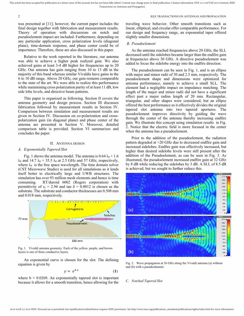
Fig. 1 shows the antenna model. The antenna is 0.64 λ0 × 1.6 λ0 and 14.7 λ0 × 35.5 λ0 at 2.5 GHz and 57 GHz, respectively, where λ0 is the free space wavelength. The time domain solver (CST Microwave Studio) is used for all simulations as it lends itself better to electrically large and UWB structures. The simulation has over 93 million mesh elements and hence is time consuming. RT/duroid 6002 (Rogers corporation) with permittivity of εr = 2.94 and tan δ = 0.0012 is chosen as the substrate. The substrate and conductor thicknesses are 0.508 mm and 0.018 mm, respectively.
Fig. 1. Vivaldi antenna geometry. Each of the yellow, purple, and brown
layers is one of three conductive layers.
An exponential curve is chosen for the slot. The defining equation is given by
� = �� � (1)
where b = 0.0269. An exponentially tapered slot is important because it allows for a smooth transition, hence allowing for the
traveling wave behavior. Other smooth transitions such as linear, elliptical, and circular offer comparable performance. For our design and frequency range, an exponential taper offered slightly smaller dimensions.
B. Pseudoelement
As the antenna reached frequencies above 20 GHz, the SLL decreased until the sidelobes became larger than the endfire gain at frequencies above 30 GHz. A directive pseudoelement was added to focus the sidelobe energy into the endfire direction.
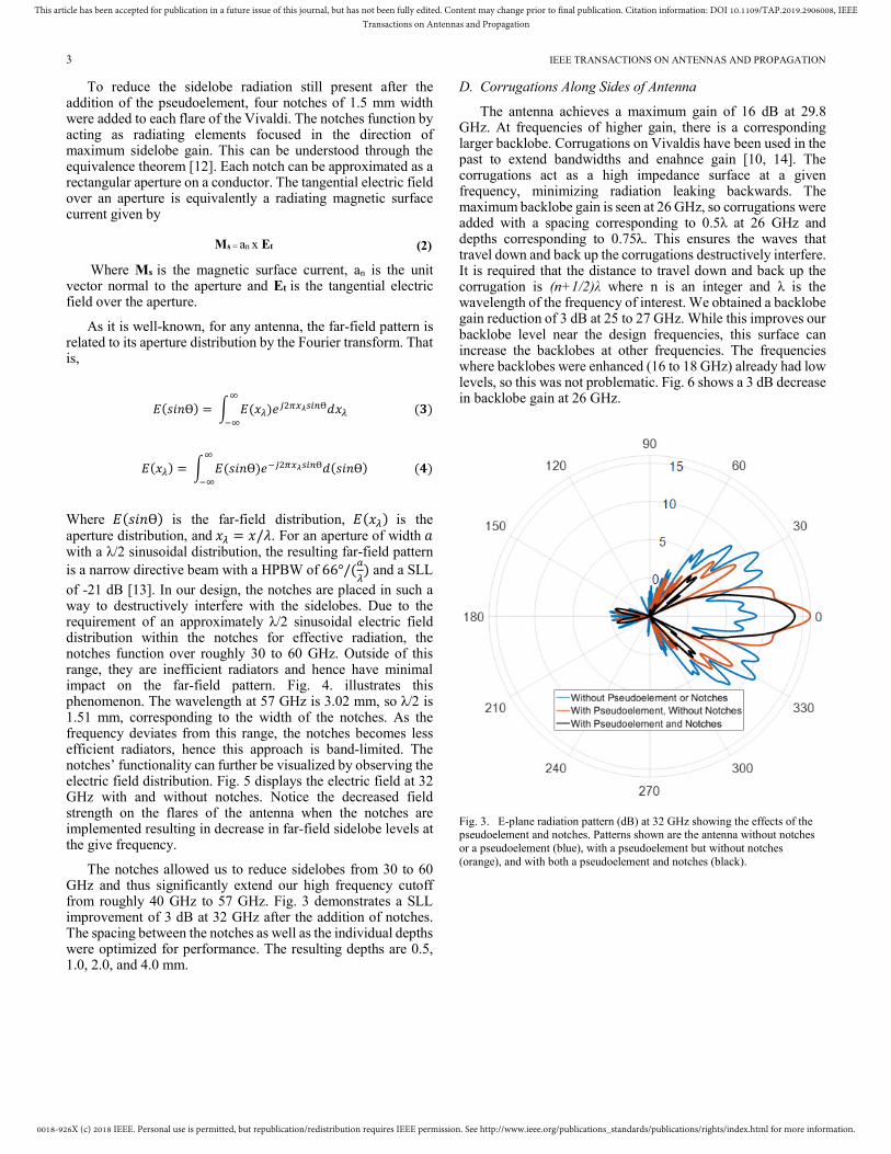
The pseudoelement can be seen in Fig. 1, and is an ellipse with major and minor radii of 30 and 2.5 mm, respectively. The pseudoelement shape and dimensions were optimized for antenna performance, namely to achieve a small SLL. The element had a negligible impact on impedance matching. The length of the major and minor radii did not have a significant effect past a major radius length of 20 mm. Rectangular, triangular, and other shapes were considered, but an ellipse offered the best performance as it effectively divides the original tapered slot antenna into two tapered apertures. The pseudoelement improves directivity by guiding the wave through the center of the antenna thereby increasing endfire gain. We illustrate this concept using simulation results in Fig. 2. Notice that the electric field is more focused in the center when the antenna has a pseudoelement.
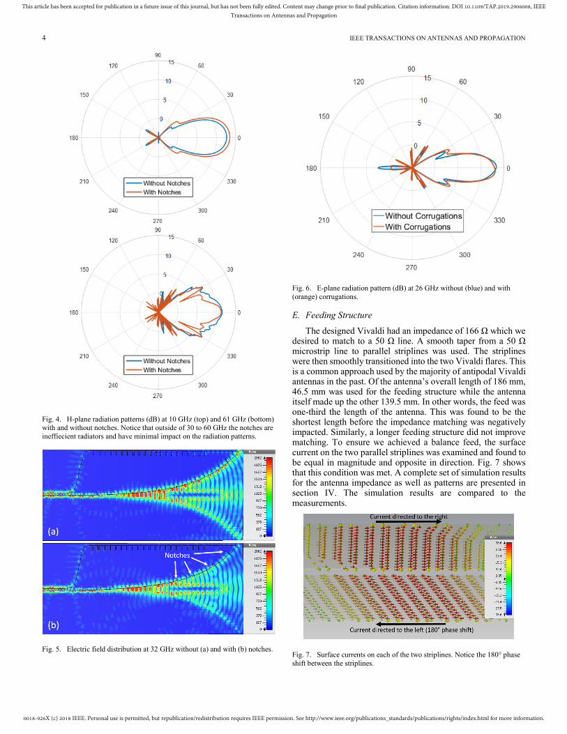
Prior to the addition of the pseudoelement, the radiation pattern degraded at >20 GHz due to decreased endfire gain and increased sidelobes. Endfire gain was effectively increased, but higher than desired sidelobe levels were still present after the addition of the Pseudoelement, as can be seen in Fig. 3. As illustrated, the pseudoelement increased endfire gain at 32 GHz by 8 dB while reducing the sidelobes by 3 dB. A SLL of 8.5 dB is achieved, but we sought to further reduce this.
Fig. 2. Wave propagation at 26 GHz along the Vivaldi antenna (a) without
and (b) with a pseudoelement.
C. Notched Tapered Slot
0018-926X (c) 2018 IEEE. Personal use is permitted, but republication/redistribution requires IEEE permission. See http://www.ieee.org/publications_standards/publications/rights/index.html for more information.
This article has been accepted for publication in a future issue of this journal, but has not been fully edited. Content may change prior to final publication. Citation information: DOI 10.1109/TAP.2019.2906008, IEEETransactions on Antennas and Propagation
3 IEEE TRANSACTIONS ON ANTENNAS AND PROPAGATION
To reduce the sidelobe radiation still present after the addition of the pseudoelement, four notches of 1.5 mm width were added to each flare of the Vivaldi. The notches function by acting as radiating elements focused in the direction of maximum sidelobe gain. This can be understood through the equivalence theorem [12]. Each notch can be approximated as a rectangular aperture on a conductor. The tangential electric field over an aperture is equivalently a radiating magnetic surface current given by
Ms = an x Et (2)
Where Ms is the magnetic surface current, an is the unit vector normal to the aperture and Et is the tangential electric field over the aperture.
As it is well-known, for any antenna, the far-field pattern is related to its aperture distribution by the Fourier transform. That is,
���Ѳ = � �����
�� ���������Ѳ��� ��
���� = � ���Ѳ�
�� ����������Ѳ���Ѳ ��
Where ���Ѳ is the far-field distribution, ���� is the aperture distribution, and �� = �/�. For an aperture of width � with a λ/2 sinusoidal distribution, the resulting far-field pattern
is a narrow directive beam with a HPBW of 66°/�"� and a SLL
of -21 dB [13]. In our design, the notches are placed in such a way to destructively interfere with the sidelobes. Due to the requirement of an approximately λ/2 sinusoidal electric field distribution within the notches for effective radiation, the notches function over roughly 30 to 60 GHz. Outside of this range, they are inefficient radiators and hence have minimal impact on the far-field pattern. Fig. 4. illustrates this phenomenon. The wavelength at 57 GHz is 3.02 mm, so λ/2 is 1.51 mm, corresponding to the width of the notches. As the frequency deviates from this range, the notches becomes less efficient radiators, hence this approach is band-limited. The notches’ functionality can further be visualized by observing the electric field distribution. Fig. 5 displays the electric field at 32 GHz with and without notches. Notice the decreased field strength on the flares of the antenna when the notches are implemented resulting in decrease in far-field sidelobe levels at the give frequency.
The notches allowed us to reduce sidelobes from 30 to 60 GHz and thus significantly extend our high frequency cutoff from roughly 40 GHz to 57 GHz. Fig. 3 demonstrates a SLL improvement of 3 dB at 32 GHz after the addition of notches. The spacing between the notches as well as the individual depths were optimized for performance. The resulting depths are 0.5, 1.0, 2.0, and 4.0 mm.
D. Corrugations Along Sides of Antenna
The antenna achieves a maximum gain of 16 dB at 29.8 GHz. At frequencies of higher gain, there is a corresponding larger backlobe. Corrugations on Vivaldis have been used in the past to extend bandwidths and enahnce gain [10, 14]. The corrugations act as a high impedance surface at a given frequency, minimizing radiation leaking backwards. The maximum backlobe gain is seen at 26 GHz, so corrugations were added with a spacing corresponding to 0.5λ at 26 GHz and depths corresponding to 0.75λ. This ensures the waves that travel down and back up the corrugations destructively interfere. It is required that the distance to travel down and back up the corrugation is (n+1/2)λ where n is an integer and λ is the wavelength of the frequency of interest. We obtained a backlobe gain reduction of 3 dB at 25 to 27 GHz. While this improves our backlobe level near the design frequencies, this surface can increase the backlobes at other frequencies. The frequencies where backlobes were enhanced (16 to 18 GHz) already had low levels, so this was not problematic. Fig. 6 shows a 3 dB decrease in backlobe gain at 26 GHz.
Fig. 3. E-plane radiation pattern (dB) at 32 GHz showing the effects of the pseudoelement and notches. Patterns shown are the antenna without notches
or a pseudoelement (blue), with a pseudoelement but without notches
(orange), and with both a pseudoelement and notches (black).
0018-926X (c) 2018 IEEE. Personal use is permitted, but republication/redistribution requires IEEE permission. See http://www.ieee.org/publications_standards/publications/rights/index.html for more information.
This article has been accepted for publication in a future issue of this journal, but has not been fully edited. Content may change prior to final publication. Citation information: DOI 10.1109/TAP.2019.2906008, IEEETransactions on Antennas and Propagation
4 IEEE TRANSACTIONS ON ANTENNAS AND PROPAGATION
Fig. 4. H-plane radiation patterns (dB) at 10 GHz (top) and 61 GHz (bottom)
with and without notches. Notice that outside of 30 to 60 GHz the notches are
ineffiecient radiators and have minimal impact on the radiation patterns.
Fig. 5. Electric field distribution at 32 GHz without (a) and with (b) notches.
Fig. 6. E-plane radiation pattern (dB) at 26 GHz without (blue) and with
(orange) corrugations.
E. Feeding Structure
The designed Vivaldi had an impedance of 166 Ω which we desired to match to a 50 Ω line. A smooth taper from a 50 Ω microstrip line to parallel striplines was used. The striplines were then smoothly transitioned into the two Vivaldi flares. This is a common approach used by the majority of antipodal Vivaldi antennas in the past. Of the antenna’s overall length of 186 mm, 46.5 mm was used for the feeding structure while the antenna itself made up the other 139.5 mm. In other words, the feed was one-third the length of the antenna. This was found to be the shortest length before the impedance matching was negatively impacted. Similarly, a longer feeding structure did not improve matching. To ensure we achieved a balance feed, the surface current on the two parallel striplines was examined and found to be equal in magnitude and opposite in direction. Fig. 7 shows that this condition was met. A complete set of simulation results for the antenna impedance as well as patterns are presented in section IV. The simulation results are compared to the measurements.
Fig. 7. Surface currents on each of the two striplines. Notice the 180° phase
shift between the striplines.

0018-926X (c) 2018 IEEE. Personal use is permitted, but republication/redistribution requires IEEE permission. See http://www.ieee.org/publications_standards/publications/rights/index.html for more information.
This article has been accepted for publication in a future issue of this journal, but has not been fully edited. Content may change prior to final publication. Citation information: DOI 10.1109/TAP.2019.2906008, IEEETransactions on Antennas and Propagation
5 IEEE TRANSACTIONS ON ANTENNAS AND PROPAGATION
F. Transient Considerations
A concern with UWB antennas is their susceptibility to dispersion due to the high frequency content in certain applications, such as ground-penetrating radar. High levels of dispersion can limit the efficacy of an antenna. The transient behavior of the proposed antenna has been quantified through its ringing behavior and group delay.
Fig. 8. displays the simulated group delay across the band. The antenna has a group delay spanning 4 ns from 2.5 to 57 GHz. The group delay remains below 2 ns for the majority of the band, indicating minimal phase shift within the operating band. This figure is in line with other Vivaldi antennas operating at similar frequencies [15].
Fig. 8. Simulated antenna group delay as a function of frequency.
The ringing is caused by energy storage or internal reflections within the antenna. Ringing can be quantified by examining how quickly the impulse response decays relative to the width of its main pulse. The duration of the impulse response envelope should ideally be no more than a few multiples of the width of the main pulse, given by its full width at half-maximum (FWHM) value [16]. The proposed antenna has a FWHM of 250 ps with an impulse response duration of 1.7 ns, indicating acceptable ringing performance. Fig. 9 displays the simulated time-domain impulse response and its envelope. This value is in line with similar UWB antennas. For instance, the Vivaldi in [17] had an 85 ps FWHM response. Furthermore, [18] discusses a spiral antenna as well as a Vivaldi antenna with a FWHM roughly 200 ps and 150 ps, respectively. Both antennas in [18] have response durations of >2 ns, similar to the antenna discussed here.
Fig. 9. Antenna time-domain impulse response and envelope.
We note that, as illustrated in Fig. 9, the main pulse is
located at 0.45 ns with two additional pulses at 0.9 and 1.4 ns.
Depending on the application, these may impose a limitation on
target resolution. Considering free space propagation, a pulse
has travel time of #$ = 2�/&, where d is the distance from the
transmitter to the target and c is the speed of light in a vacuum.
Rearranging this yields � = & #$/2. The main pulse and the
pulse at 1.4 ns are separated by 0.95 ns. This translates into a
limitaton that objects within 0.14 meters of each other can not
be resolved with the proposed antenna. Therefore, the antenna
has limitations for certain applications.
III. FABRICATION
The antenna was fabricated on a RT/duroid 6002 substrate with three conductive layers. This particular laminate was chosen for several reasons: First, as compared to other laminates, the high frequency performance up to 40 GHz is favorable. The dielectric constant is stable (εr = 2.94 at 8–40 GHz) and losses are low (tan δ = 0.0012 at 10 GHz). Given the very wide bandwidth nature of our design, the fact that the laminate is intended for operating to at least 40 GHz guaranteed that for approximately two-third of the band, it acts as expected. Second, the laminate has a very low thermal coefficient of expansion (CTE= 24 ppm/°C in Z direction) that results in higher reliability and better matching with the copper layers. Third, it is suitable for space applications due to low outgassing. Fourth, the fabrication and material costs were reasonable
The pseudoelement needed to be halfway between the two antipodal Vivaldi layers, so the antenna was split into two 0.254 mm thick substrates. The pseudoelement was fabricated on one layer, then 0.0381 mm thick Rogers 3001 bonding film, εr = 2.28, was used to join the layers. This thin layer was taken into account during simulations, as it resulted in the pseudoelement to be slightly off-centered. This reduced our high frequency cutoff from 59 GHz to 57 GHz due to degradation of radiation patterns at the end of the band. Conductor thickness was 0.018

0018-926X (c) 2018 IEEE. Personal use is permitted, but republication/redistribution requires IEEE permission. See http://www.ieee.org/publications_standards/publications/rights/index.html for more information.
This article has been accepted for publication in a future issue of this journal, but has not been fully edited. Content may change prior to final publication. Citation information: DOI 10.1109/TAP.2019.2906008, IEEETransactions on Antennas and Propagation
6 IEEE TRANSACTIONS ON ANTENNAS AND PROPAGATION
mm. Prior to fabrication, minimum line widths were ensured to be a large enough for easy manufacturing.
Fig. 10. Top and bottom view of the fabricated antenna. Note that the
pseudoelement is not visible because it is in the center layer.
A 1.85mm end launch connector (model # 1892-04A-5 from Southwest Microwave) was used to feed the microstrip. This connector is rated up to 67 GHz. For 2 to 40 GHz measurements, a 1.85mm male to 2.92mm female adapter (SM3960 from Fairview Microwave) was used. The fabricated prototype is shown in Fig. 10. We note that since the pseudoelement is fabricated in the middle layer, it is not visible in this figure. The measurement set up is shown in Fig. 11. The antenna is encapsulated between two foam slabs in order to ensure it is completely flat.
IV. MEASUREMENTS
Reflection coefficient measurements were done over 1 to 40 GHz and 40 to 57 GHz ranges. For frequencies as low as 2.5 GHz, we achieved a VSWR of less than 3 (both simulated and measured) as can be seen from Fig. 12. The majority of the band has a VSWR of less than 2, but there were a few narrows spikes above this in simulations. We achieve excellent agreement between the simulated and measured results. Measured VSWR remains below 2 above 7 GHz. It is implied from Fig. 12. that the antenna can operate above 57 GHz. While it is sufficiently matched above 57 GHz, radiation pattern degradation is observed above this frequency. An example of this degradation is shown in Fig. 14. Notice the irregularities of the main lobe as well as the SLL approaching zero as we operate above 57 GHz. Additionally, there are two large sidelobes at 30° to either side of the main beam.
Fig. 11. (a) The antenna under test (AUT), encapsulated in foam, is mounted atop a rotating foam column. The antenna is fed via a horn antenna directed at
a parabolic reflector. (b) Back view of the foam capsule with the connector
visible. The Vivaldi antenna is between the two foam slabs. (c) Top view of
the foam capsule.
Fig. 12. Simulated (blue) and measured (red) VSWR from 1 to 57 GHz.
Due to UWB nature of the antenna, the endfire gain measurements were broken into four discrete bands: 2.5 to 18 GHz, 18 to 26 GHz, 26 to 40 GHz, and 40 to 57 GHz. These
0018-926X (c) 2018 IEEE. Personal use is permitted, but republication/redistribution requires IEEE permission. See http://www.ieee.org/publications_standards/publications/rights/index.html for more information.
This article has been accepted for publication in a future issue of this journal, but has not been fully edited. Content may change prior to final publication. Citation information: DOI 10.1109/TAP.2019.2906008, IEEETransactions on Antennas and Propagation
7 IEEE TRANSACTIONS ON ANTENNAS AND PROPAGATION
bands correspond to the feed horns used in our measurements as well. Radiation patterns were measured simultaneously with endfire gain with the exception of the 40 to 57 GHz band. Measurements were performed in the Ohio State ElectroScience Laboratory anechoic chamber. Frequency steps of 5 MHz and 10 MHz were used for 2.5 to 20 GHz and 20 to 40 GHz, respectively. A different VNA was used for 20 to 40 GHz measurements which is why the step size differs. Due to a limitation of lab equipment and complexity of pattern measurement at the millimeter wave band, only VSWR and endfire gain was measured at 40 to 57 GHz.
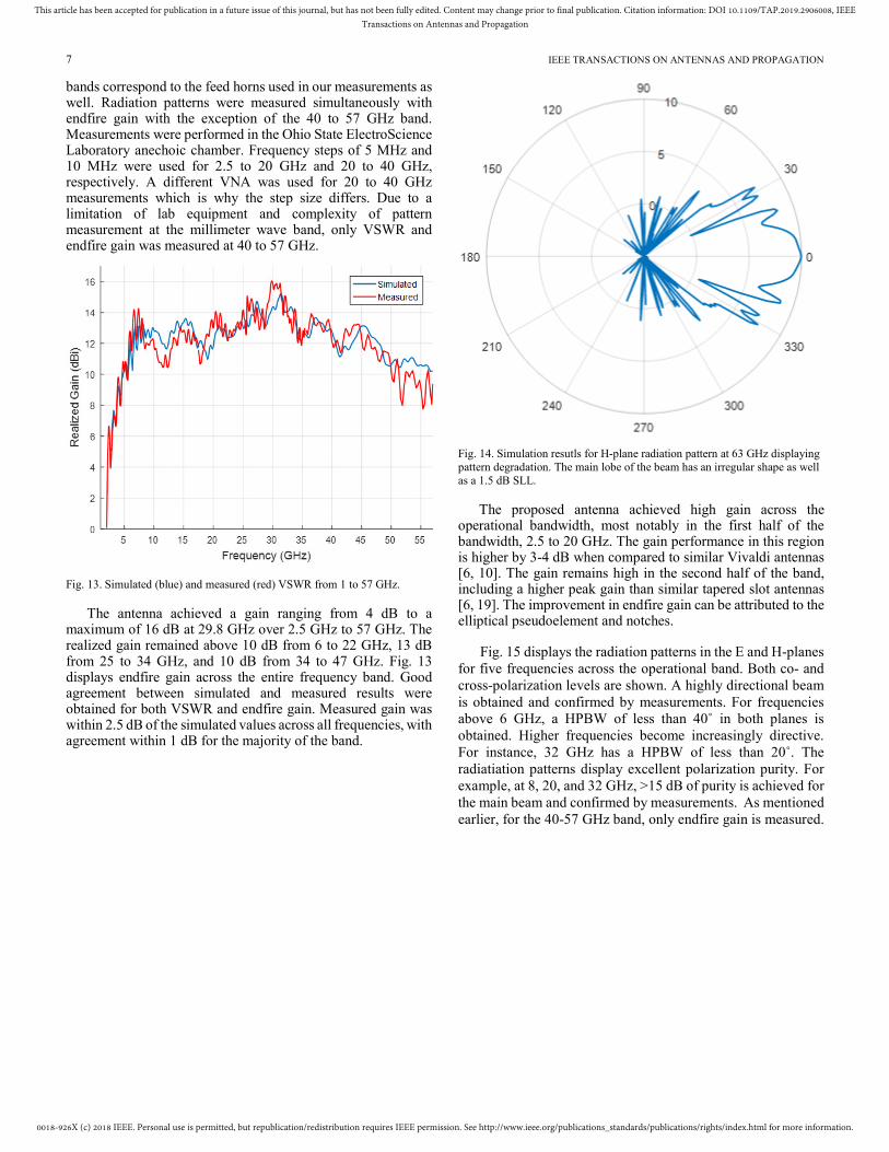
Fig. 13. Simulated (blue) and measured (red) VSWR from 1 to 57 GHz.
The antenna achieved a gain ranging from 4 dB to a maximum of 16 dB at 29.8 GHz over 2.5 GHz to 57 GHz. The realized gain remained above 10 dB from 6 to 22 GHz, 13 dB from 25 to 34 GHz, and 10 dB from 34 to 47 GHz. Fig. 13 displays endfire gain across the entire frequency band. Good agreement between simulated and measured results were obtained for both VSWR and endfire gain. Measured gain was within 2.5 dB of the simulated values across all frequencies, with agreement within 1 dB for the majority of the band.
Fig. 14. Simulation resutls for H-plane radiation pattern at 63 GHz displaying
pattern degradation. The main lobe of the beam has an irregular shape as well
as a 1.5 dB SLL.
The proposed antenna achieved high gain across the operational bandwidth, most notably in the first half of the bandwidth, 2.5 to 20 GHz. The gain performance in this region is higher by 3-4 dB when compared to similar Vivaldi antennas [6, 10]. The gain remains high in the second half of the band, including a higher peak gain than similar tapered slot antennas [6, 19]. The improvement in endfire gain can be attributed to the elliptical pseudoelement and notches.
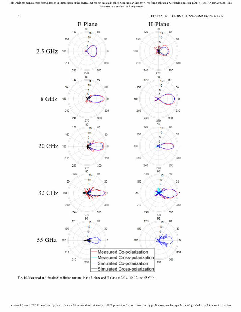
Fig. 15 displays the radiation patterns in the E and H-planes
for five frequencies across the operational band. Both co- and
cross-polarization levels are shown. A highly directional beam
is obtained and confirmed by measurements. For frequencies
above 6 GHz, a HPBW of less than 40˚ in both planes is
obtained. Higher frequencies become increasingly directive.
For instance, 32 GHz has a HPBW of less than 20˚. The
radiatiation patterns display excellent polarization purity. For
example, at 8, 20, and 32 GHz, >15 dB of purity is achieved for
the main beam and confirmed by measurements. As mentioned
earlier, for the 40-57 GHz band, only endfire gain is measured.
0018-926X (c) 2018 IEEE. Personal use is permitted, but republication/redistribution requires IEEE permission. See http://www.ieee.org/publications_standards/publications/rights/index.html for more information.
This article has been accepted for publication in a future issue of this journal, but has not been fully edited. Content may change prior to final publication. Citation information: DOI 10.1109/TAP.2019.2906008, IEEETransactions on Antennas and Propagation
8 IEEE TRANSACTIONS ON ANTENNAS AND PROPAGATION
Fig. 15. Measured and simulated radiation patterns in the E-plane and H-plane at 2.5, 8, 20, 32, and 55 GHz.

0018-926X (c) 2018 IEEE. Personal use is permitted, but republication/redistribution requires IEEE permission. See http://www.ieee.org/publications_standards/publications/rights/index.html for more information.
This article has been accepted for publication in a future issue of this journal, but has not been fully edited. Content may change prior to final publication. Citation information: DOI 10.1109/TAP.2019.2906008, IEEETransactions on Antennas and Propagation
9 IEEE TRANSACTIONS ON ANTENNAS AND PROPAGATION
V. DISCUSSION
Antipodal Vivaldi antennas are known to have high cross-polarization levels because the E-field is skewed due to the two flares being on opposite sides of the substrate. One method to avoid this problem is to use a thin substrate as this minimizes the vertical separation between the two flares. We sought to maintain a polarization purity of 10 dB across all operating frequencies. As shown in Fig. 15, 11 dB of polarization purity is achieved for the main beam across the entire band, with most frequencies having polarization purities greater than 15 dB. Many works did not report polarization purity [14, 19]. [b] reported polarization purity of at least 15 dB while [20] displays purities down to 13 dB. Thus our antenna has comparable performance in this regard.
Vivaldi antennas occasionally have high cross polarization levels in the diagonal plane (D-plane), but the proposed antenna does not suffer from this. To illustrate D-plane purity, a far field 3D plot of the cross-polarization at 32 GHz is shown in Fig. 16. Performance across the band was similar with a D-plane purity of at least 11 dB. Polarization purity performance can be attributed to the thin substrate as the two flares of the tapered slot are nearly coplanar. This also contributes to the high quality radiation patterns since a thin substrate does not support higher order modes at the higher end of the band.
Fig. 16. 3D far field plots at 32 GHz of (a) co-polarization and (b) cross-polarization. Note that over 14 dB of polarization purity is achieved over the
main beam. Cross-polarization levels in this region do not go above 0.5 dB.
Additionally, the phase center is yet another important parameter for applications including radar and GNSS.. Simulated phase center results are provided in Fig. 17. Overall phase center variations were 70 mm and 60 mm in the E-Plane and H-Plane, respectively. This corresponds to 11.3 and 13.2 free space wavelengths at 57 GHz.
Fig. 17. Simulated phase center for the E- and H-Plane.
The proposed antenna offers high gain of >7.6 dB above 6 GHz with a peak measured gain of 16 dB. Additionally, radiation patterns are favorable in that they are symmetric, directive, and have low SLL and BLL. A SLL of 10 dB is achieved for the majority of the band, with the exceptions below 6 GHz due to lower gain and above 45 GHz. These frequencies maintain a SLL of 4 dB. A BLL of at least 10 dB is achieved across the operational band, excluding frequencies below 6 GHz once again due to lower gain.
Table I summarizes the comparison of the proposed antenna to those reported in the literature. Our antenna achieves a larger peak gain as well as an increased bandwidth. To the knowledge of the authors, this work achieves a larger bandwidth than any comparable basic antipodal Vivaldi in the literature. We have also achieved a higher average gain. Our gain is lower than [21], though that work implemented Teflon layers (lens) surrounding the antenna. This makes fabrication more costly and time-consuming when compared to simple PCB fabrication.
We have defined our bandwidth as VSWR < 3 while some works on UWB define bandwidth as VSWR < 2 or 2.5, however our measured VSWR remains below 2 for the vast majority of the band besides a few brief spikes. We have also achieved a high peak realized gain and average gain. Our antenna is larger than most references in the table, but this can be attributed to its higher gain and wider bandwidth. Endfire gain at specific frequencies is also shown for each antenna to better illustrate performance over the operational band.

0018-926X (c) 2018 IEEE. Personal use is permitted, but republication/redistribution requires IEEE permission. See http://www.ieee.org/publications_standards/publications/rights/index.html for more information.
This article has been accepted for publication in a future issue of this journal, but has not been fully edited. Content may change prior to final publication. Citation information: DOI 10.1109/TAP.2019.2906008, IEEETransactions on Antennas and Propagation
10 IEEE TRANSACTIONS ON ANTENNAS AND PROPAGATION
TABLE I
COMPARISON OF PROPOSED VIVALDI ANTENNA
Work Dimensions
( mm3)
Peak
Realized
Gain
(dB)
Frequency
(GHz) →
Gain (dB)
Operational
Bandwidth
(GHz)
[10] 40 × 90 ×
0.51 15
4 → 7
20 → 12.5 40 → 14
3.4 - 40
[22] 30 × 55 ×
0.51 <14
5 → 6
20 → <12 40 → 13.5
5.0 - 50
[6] 64 × 61 ×
0.25 <15
5 → 5
20 → 10
40 → 14.5
4.0 - 50
[23] 96 × 100 ×
0.51 12
4 → 7.5 20 → 12
2.1 - 27
[19] 50.8 × 62 ×
0.80 10
4 → 5
20 → 9 1.3 - 20
[14] 50 × 62 ×
1.52 <11
3 → 6 8 → 10
1.96 - 8.61
[20] 8 × 59 × 0.50 13 25 → >10
40 → 12 25 - 40
[21] 31.6 × 110 ×
N/A <21
5 → >6 20 → 17
40 → <21
5.0 - 50
[9] 40 × 100 × 1 10.55
5 → >7
20 → 9.5
40 → >5
2.8 - 40
[5] 20 × 34 ×
N/A <12.5
5 → 11 20 → 11.5
40 → 2
1.0 - 40
[4] 151 × 140 ×
1.6 N/A
1 → 3
3 → 6
8 → <10
0.73 - 20
This
Work
77 × 186 ×
0.55 16
4 → 10
20 → 12
40 → 14
2.5 - 57
(VSWR < 3)
VI. CONCLUSION
This paper presents a novel design for an UWB Vivaldi antenna with high gain performance across the 2.5-57 GHz band by employing a pseudoelement to enhance directivity, notched flares to reduce sidelobe levels, and corrugations to reduce backlobe levels. Maximum and minimum gains of 16 and 4 dB are achieved, respectively, across the band. A larger bandwidth (22.8:1) and higher peak gain is presented when compared to similar UWB tapered slot antennas. The antenna offers directive radiation patterns with a HPBW below 40˚ above 6 GHz, with some frequencies having a HPBW as low as <20˚ The low profile, high gain, low sidelobe and backlobe levels, and ultra wide bandwidth make this antenna a good candidate for remote sensing, imaging systems, and defense applications.
REFERENCES
[1] P. Gibson, “The Vivaldi Aerial,” 1979 9th European Microwave Conference, 1979.
[2] E. Gazit, “Improved design of the Vivaldi antenna,” IEEE Proceedings H Microwaves, Antennas and Propagation, vol. 135, no. 2, p. 89, 1988.
[3] J. Langley, P. Hall, and P. Newham, “Novel ultrawide-bandwidth Vivaldi antenna with low crosspolarisation,” Electronics Letters, vol. 29, no. 23, p. 2004, 1993.
[4] S. A. Abdelbaky and H. F. Hammad, “Modified Elliptical Antipodal Vivaldi Antenna with Elliptical Tapered Slot Edge and Circular loads,” 2017 International Workshop on Antenna Technology: Small Antennas, Innovative Structures, and Applications (iWAT), 2017.
[5] J. Fisher, “Design and Performance Analysis of a 1-40 GHz Ultra-Wideband Antipodal Vivaldi Antenna,” German Radar Symposium GRS, 2000.
[6] J. Bai, S. Shi, and D. W. Prather, “Modified Compact Antipodal Vivaldi Antenna for 4–50-GHz UWB Application,” IEEE Transactions on Microwave Theory and Techniques, vol. 59, no. 4, pp. 1051–1057, 2011.
[7] I. T. Nassar and T. M. Weller, “A Novel Method for Improving Antipodal Vivaldi Antenna Performance,” IEEE Transactions on Antennas and Propagation, vol. 63, no. 7, pp. 3321–3324, 2015.
[8] M. H. H. Agahi, H. Abiri, and F. Mohajeri, “Investigation of a New Idea for Antipodal Vivaldi Antenna Design,” International Journal of Computer and Electrical Engineering, pp. 277–281, 2011.
[9] J. Sun, L. Du, and W. Jiang, “Design of ultra-wideband antipodal Vivaldi antenna for target RCS imaging,” 2015 IEEE International Wireless Symposium (IWS 2015), 2015.
[10] M. Moosazadeh and S. Kharkovsky, “A Compact High-Gain and Front-to-Back Ratio Elliptically Tapered Antipodal Vivaldi Antenna With Trapezoid-Shaped Dielectric Lens,” IEEE Antennas and Wireless Propagation Letters, vol. 15, pp. 552–555, 2016.
[11] J. Eichenberger, E. Yetisir, and N. Ghalichechian, “Antipodal UWB Vivaldi Antenna with Pseudoelement and Notched Flares for 2.5-57 GHz Applications,'' IEEE International Symposium on Antennas and Propagation & USNC/URSI National Radio Science Meeting, 2018.
[12] C. A. Balanis, Advanced Engineering Electromagnetics. Hoboken: J. Wiley & Sons, 2012.
[13] J. D. Kraus and R. J. Marhefka, Antennas for all applications. Boston, MA: McGraw-Hill, 2002.
[14] M. Abbak, M. N. Akinci, M. Cayoren, and I. Akduman, “Experimental Microwave Imaging With a Novel Corrugated Vivaldi Antenna,” IEEE Transactions on Antennas and Propagation, vol. 65, no. 6, pp. 3302–3307, 2017.
[15] Z. Li, X. Kang, J. Su, Q. Guo, Y. (L. Yang, and J. Wang, “A Wideband End-Fire Conformal Vivaldi Antenna Array Mounted on a Dielectric Cone,” International Journal of Antennas and Propagation, vol. 2016, pp. 1–11, 2016.
[16] W. Wiesbeck, G. Adamiuk, and C. Sturm, “Basic Properties and Design Principles of UWB Antennas,” Proceedings of the IEEE, vol. 97, no. 2, pp. 372–385, 2009.
[17] J. Bourqui, M. Okoniewski, and E. C. Fear, “Balanced Antipodal Vivaldi Antenna With Dielectric Director for Near-Field Microwave Imaging,” IEEE Transactions on Antennas and Propagation, vol. 58, no. 7, pp. 2318–2326, 2010.
[18] H. Liu, J. Zhao, and M. Sato, “A Hybrid Dual-Polarization GPR System for Detection of Linear Objects,” IEEE Antennas and Wireless Propagation Letters, vol. 14, pp. 317–320, 2015.
[19] B. Biswas, R. Ghatak, and D. R. Poddar, “A Fern Fractal Leaf Inspired Wideband Antipodal Vivaldi Antenna for Microwave Imaging System,” IEEE Transactions on Antennas and Propagation, vol. 65, no. 11, pp. 6126–6129, 2017.
[20] J. Puskely, J. Lacik, Z. Raida, and H. Arthaber, “High-Gain Dielectric-Loaded Vivaldi Antenna for Ka-Band Applications,” IEEE

0018-926X (c) 2018 IEEE. Personal use is permitted, but republication/redistribution requires IEEE permission. See http://www.ieee.org/publications_standards/publications/rights/index.html for more information.
This article has been accepted for publication in a future issue of this journal, but has not been fully edited. Content may change prior to final publication. Citation information: DOI 10.1109/TAP.2019.2906008, IEEETransactions on Antennas and Propagation
11 IEEE TRANSACTIONS ON ANTENNAS AND PROPAGATION
Antennas and Wireless Propagation Letters, vol. 15, pp. 2004–2007, 2016.
[21] M. Moosazadeh, “High-Gain Antipodal Vivaldi Antenna Surrounded by Dielectric for Wideband Applications,” IEEE Transactions on Antennas and Propagation, vol. 66, Aug. 2018.
[22] M. Moosazadeh, S. Kharkovsky, J. T. Case, and B. Samali, “Improved Radiation Characteristics of Small Antipodal Vivaldi Antenna for Microwave and Millimeter-Wave Imaging Applications,” IEEE Antennas and Wireless Propagation Letters, vol. 16, pp. 1961-1964, Apr. 2017.
[23] M. Moosazadeh and S. Kharkovsky, “Design of Ultra-Wideband Antipodal Vivaldi Antenna for Microwave Imaging Applications,” 2015 IEEE International Conference on Ubiquitous Wireless Broadband (ICUWB), 2015.
Jack Eichenberger is a graduate
student and research assistant at the
Department of Electrical and Computer
Engineering and the ElectroScience
Laboratory at the Ohio State University.
He received the BS degree in electrical
engineering (magna cum laude) in
February 2017 from Rose-Hulman
Institute of Technology. He is currently
pursuing his Ph.D. under supervision of Nima Ghalichechian.
His research interests include ultra-wideband antennas,
reconfigurable antennas, and metasurfaces in antenna
applications. He currently serves as a reviewer for IET
Microwaves, Antennas & Propagation. Jack was a university
fellow during the 2017-2018 academic year. He has been
awarded the Air Force Research Laboratory SFFP fellowship
for the summer of 2019.
Ersin Yetisir (S'11, M'16) received
the B.Sc. degree in electrical and
electronics engineering from Bilkent
University, Ankara, Turkey in 2010 and
Ph.D. degree from The Ohio State
University, Columbus, OH, USA, in
2015. From 2010 to 2015, he was a
Graduate Research Assistant and
during 2016 Feb-Aug, a Postdoctoral
Researcher at the ElectroScience Lab (ESL). He worked on
wideband & low-profile antenna array and feed-network
design for microwave and millimeter-wave frequencies,
wideband/multiband antennas with high isolation for MIMO
and STAR applications. Since 2016 Aug, he is with SpaceX
where he has been helping in design and characterization of
low cost phased array apertures & front-end components and
developing calibration methods for satellite & ground
terminals. Dr. Yetisir received the best student paper awards
at the 2016 USNC/URSI National Radio Science Meeting
(2nd place) and 2016 International Workshop on Antenna
Technologies (co-author)
Nima Ghalichechian (S’99–M’08–
SM’14) is an Assistant Professor at the
Department of Electrical and Computer
Engineering and the ElectroScience
Laboratory at the Ohio State
University. He received his Ph.D. in
Electrical Engineering in 2007 from
University of Maryland, College Park
where he developed MEMS
electrostatic micromotors supported on
microball bearings. From 2007 to 2012 he was with the
Research Department of FormFactor Inc., Livermore,
California as a Senior Principal Engineer. During this period,
he helped to design and develop MEMS microsprings for
advanced probe cards used in testing memory and SoC
semiconductor devices. Dr. Ghalichechian joined The Ohio
State University as a Research Scientist in 2012. As a
principal investigator, he established several new programs
sponsored by NSF, DARPA, and AFRL. From 2016-2017, he
held a Research Assistant Professor position. He transitioned
into an Assistant Professor position in August 2017. He is
currently a principal investigator and director of the RF
Microsystems Laboratory and advises 7 doctoral and 2
masters’ students. His research interests include phase-
change materials, reconfigurable antennas, arrays, UWB
antennas, millimeter-wave systems, meta-surfaces, 3D-
printed antennas, novel materials, and microfabrication
techniques. Professor Ghalichechian is the recipient of 2019
NSF CAREER Award, 2019 Air Force Research Laboratory
Summer Faculty Fellowship Award, and 2018 Ohio State
University Lumley Research Award.