high-level data link control (hdlc) hdlc was defined by iso for use on both point-to-point and...
TRANSCRIPT
HIGH-LEVEL DATA LINK CONTROL (HDLC)
• HDLC was defined by ISO for use on both point-to-point and multipoint data links.• It supports full-duplex communication• Other similar protocols are• Synchronous Data Link Control (SDLC) by IBM• Advanced Data Communication Control
Procedure (ADCCP) by ANSI• Link Access Procedure, Balanced (LAP-B) by
CCITT, as part of its X.25 packet-switched network standard
HDLC OVERVIEW
Broadly HDLC features are as follows:• Reliable protocol• Full-duplex communication• receive and transmit at the same time
• Bit-oriented protocol• use bits to stuff flags occurring in data
• Flow control• adjust window size based on receiver capability
• Uses physical layer clocking and synchronization to send and receive frames

HDLC OVERVIEW
• Defines three types of stations• Primary• Secondary• Combined

• Primary station • Has the responsibility of controlling the
operation of data flow the link. • Handles error recovery• Frames issued by the primary station
are called commands.
• Secondary station, • Operates under the control of the
primary station. • Frames issued by a secondary station
are called responses.• The primary station maintains a
separate logical link with each secondary station.

• Combined station, • Acts as both as primary and secondary
station.• Does not rely on other for sending data

HDLC
Primary
Secondary Secondary
Commands
Responses
Combined Combined
commands/Responses
Unbalanced Mode
Balanced mode

• Defines three types of data transfer mode• Normal Response mode• Asynchronous Response mode• Asynchronous Balanced mode

HDLC
• Three modes of data transfer operations

• Normal Response Mode (NRM) • Mainly used in terminal-mainframe
networks. In this case, • Secondaries (terminals) can only
transmit when specifically instructed by the primary station in response to a polling• Unbalanced configuration, good for
multi-point links

• Asynchronous Response Mode (ARM) • Same as NRM except that the
secondaries can initiate transmissions without direct polling from the primary station• Reduces overhead as no frames need
to be sent to allow secondary nodes to transmit• Transmission proceeds when channel is
detected idle , used mostly in point-to-point-links

• Asynchronous Balanced Mode (ABM) • Mainly used in point-to-point links, for
communication between combined stations

NON-OPERATIONAL MODES
• Normal Disconnected Mode• Asynchronous Disconnected Mode
Both the above modes mean that the secondary node is logically disconnected from the primary node
• Initialization Mode• A node negotiates transmission parameters with the
other node E.g., flow control information• Parameters negotiated in this mode are used during any
of the data transfer modes

FRAME STRUCTURE
• Synchronous transmission• All transmissions in frames• Single frame format for all data and control
exchanges

FRAME STRUCTURE
01111110 01111110
Defines 3 types of frames (I,S,U frames)

FLAG FIELDS
• Delimit frame at both ends• 01111110• Receiver hunts for flag sequence to synchronize• Bit stuffing used to avoid confusion with data
containing 01111110• The transmitter inserts 0 bit after every sequence of five
1s with the exception of flag fields• If receiver detects five 1s it checks next bit• If 0, it is deleted• If 1 and seventh bit is 0 (i.e., 10), accept as flag• If sixth and seventh bits 1 (i.e., 11), sender is indicating abort


DATA LINK CONTROL HDLC FRAME STRUCTURE
(a) Frame Format
(b) Control field format

ADDRESS FIELD• Identifies secondary station that sent or will receive
frame• Usually 8 bits long• May be extended to multiples of 7 bits• LSB of each octet indicates that it is the last octet (1) or not
(0)
• All ones (11111111) is broadcast

CONT.
• Address field: • mainly used in multidrop link
configuration, and not used in point-to-point • In unbalanced configuration, every
secondary is assigned a unique address. Contains address of secondary station in both command and response frames• In balanced mode, command frame has
destination address and response frame has sending node’s address• Group addresses are also possible. E.g.,
One command sent to all the secondaries
CONTROL FIELD
• Different for different frame type• I-frame (information frame) • data to be transmitted to user (next layer up)• Flow and error control piggybacked on information frames
• S-frame (Supervisory frame)• Used for flow and error control
• U-frame (Unnumbered frame)• supplementary link control
• First one or two bits of control filed identify frame type
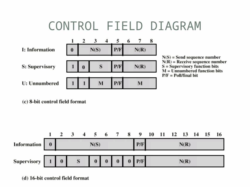
CONTROL FIELD DIAGRAM

POLL/FINAL BIT
• Use depends on context• Command frame• P bit : used for poll from primary• 1 to solicit (poll) response from peer
• Response frame• F bit : used for response from secondary• 1 indicates response to soliciting command

• Three types of frames• Unnumbered• information• Supervisory

HDLC
• There are three different classes of frames used in HDLC• Unnumbered frames, used in link setup
and disconnection, and hence do not contain ACK.• Information frames, which carry actual
information. Such frames can piggyback ACK in case of ABM• Supervisory frames, which are used for
error and flow control purposes and hence contain send and receive sequence numbers
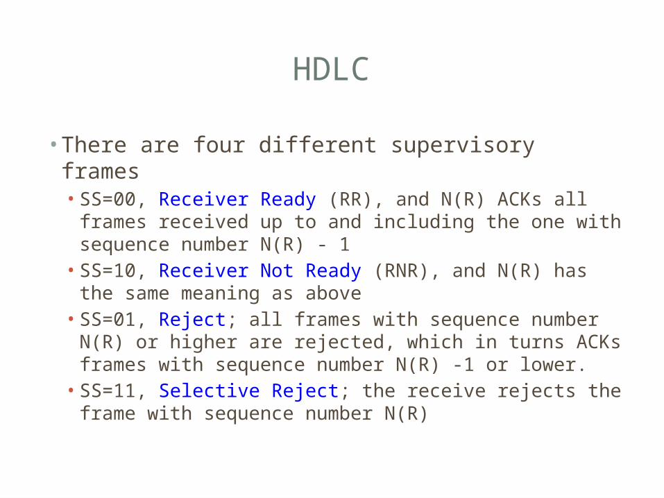
HDLC
• There are four different supervisory frames• SS=00, Receiver Ready (RR), and N(R) ACKs all
frames received up to and including the one with sequence number N(R) - 1
• SS=10, Receiver Not Ready (RNR), and N(R) has the same meaning as above
• SS=01, Reject; all frames with sequence number N(R) or higher are rejected, which in turns ACKs frames with sequence number N(R) -1 or lower.
• SS=11, Selective Reject; the receive rejects the frame with sequence number N(R)

HDLC
• The unnumbered frames can be grouped into the following categories:• Mode-setting commands and responses• Recovery commands and responses• Miscellaneous commands and responses
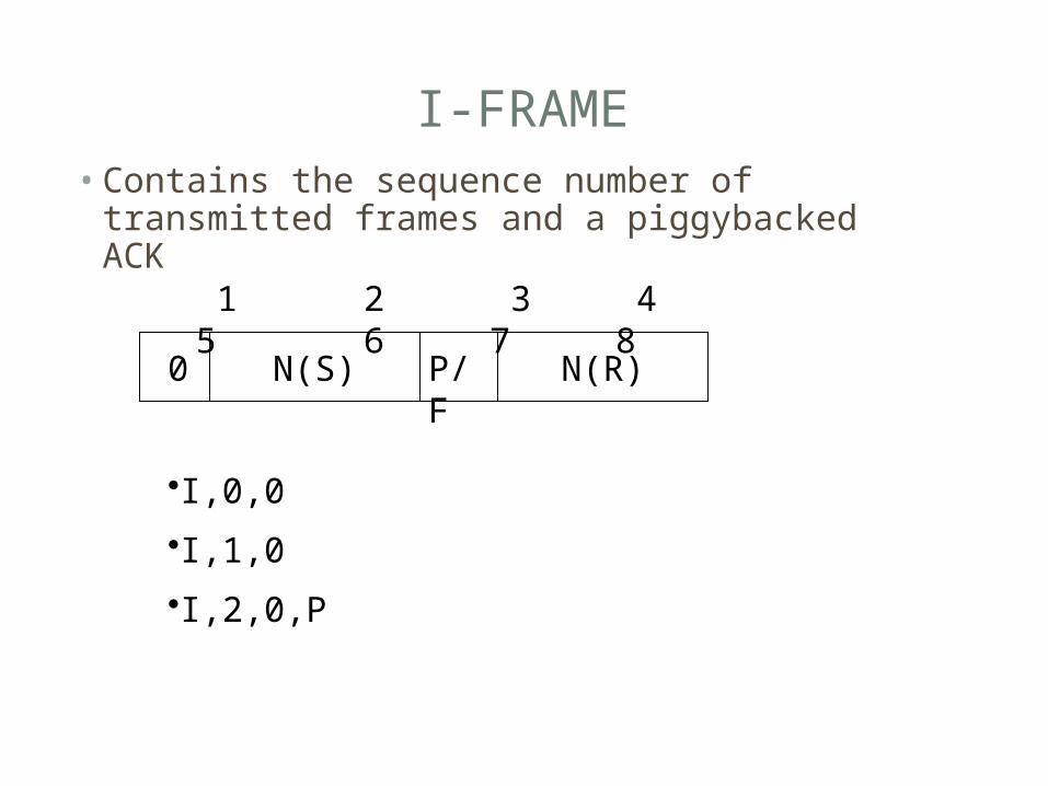
I-FRAME• Contains the sequence number of transmitted
frames and a piggybacked ACK
1 2 3 4 5 6 7 8
0 N(S) P/F N(R)
•I,0,0
•I,1,0
•I,2,0,P

S-FRAME• Used for flow and error control
1 2 3 4 5 6 7 8
1 S P/F N(R)
•RR --- receive ready
•RNR --- receive not ready
•REJ --- reject on frame N(R)
•SREJ --- selective reject on N(R)
0

U-FRAME• Mode setting, recovery, connect/diconnect
1 2 3 4 5 6 7 8
1 M P/F M1
Unnumbered function bits

FRAME CHECK SEQUENCE FIELD
• FCS• Error detection• 16 bit CRC• Optional 32 bit CRC

HDLC OPERATION
• Exchange of information, supervisory and unnumbered frames• Three phases• Initialization• Data transfer• Disconnect
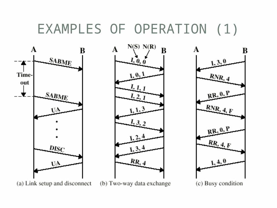
EXAMPLES OF OPERATION (1)

EXAMPLES OF OPERATION (2)