high level synthesis for design of video processing...
TRANSCRIPT

Department of Electrical Engineering and InformationTechnology
Master of Science Thesis
High Level Synthesis for Design of VideoProcessing Blocks
Authors:Ayla ChaboukCarlos Gómez
Supervisors:Joachim Rodrigues
Thomas Lenart
March 20, 2015

Printed in SwedenE-huset, Lund, 2015

Abstract
Nowadays the technology is progressing continuously. The designers are devel-oping products with new features and always giving to the user an innovativetechnological solution for the society problems. The standard methods to designnew devices are becoming slower for the demand of the products. Due to thisgrowing complexity, some possible substitutes of the traditional Register TransferLevel (RTL) design flow has been appeared. This situation is becoming a biggerproblem which needs to be solved and that is why many opened researches existabout it.
In the early 90s started the idea of High Level Synthesis (HLS) and in the ac-tual market is getting more relevance like a substitution of the standard designingmethods. In a brief description, High Level Synthesis is an automatic compilationtechnique that translates a software program to a hardware circuit. The criticalstep to jump to this new field is if High Level Synthesis will give to the designers,at least, the same design possibilities and the same quality of results as handwrit-ten hardware design. During the last ten years many companies and academicorganizations has emerged which have been developing new tools for High LevelSynthesis.
The scope of this Master’s Thesis is to evaluate one of these commercial tools(Catapult from Calypto), to understand the possibilities and the limitations ofit. The purpose of the thesis is to study, analyze and test the tool with referencemodels (video blocks) provided by ARM Sweden. The handwritten RTL descrip-tion of the models, were provided by ARM to be used to verify and compare thecorrectness and the QoR (Quality of Results) of the RTL generated by the HLStool, Catapult.
After developing the Master’s Thesis, Catapult obtained the same functional-ity, the same performance and the same operating frequency with all the blocksworked with. However, the principal limitation of Catapult that was experiencedduring the work, is the total area of the generated RTL in more complex designs.The two larger designs developed in Catapult resulted in a larger area score resultafter synthesis compared with the handwritten RTL. Apart from this issue, HLSgives a huge advantage in comparison with handwritten RTL: the short time it
i

takes to develop a complete hardware design and the possibility to explore differentarea/performance trade-off.
ii

Acknowledgement
This Master’s Thesis would not be possible without the support and guidance ofboth of our supervisors. We would like to thank to Thomas Lenart, our supervisorat ARM, for all the daily meeting and for his valuable comments and advices duringthe thesis work. He was always available for help with the countless problems thatwe faced during the last months. His attention and inspiration dedicated to usduring the time we spent working with him is invaluable. We would also like tothank to Joachim Rodrigues, our supervisor at LTH, for encouraging our ideasand for the many insightful suggestions. He was always trying to get the best ofus. All we have learnt through the master’s program and the thesis is somethingthat we will never forget.
We would like to thank to ARM for having trust on us and giving us thepossibility of doing the thesis with them. We want to thank them for makingour stay over the last six months comfortable and for proving us the latest andadvanced tools and access to all the facilities.
We would like to thank to Calypto for all the support, clarifications and guid-ance that they have given to us during the thesis.
We would like to express our gratitude to all the person involved in our edu-cation in both universities, LTH and ETSIT, that have helped us to improve ourskills and our knowledge during the last 6 years. We are really thankful with themdue to giving us the opportunity of living this great experience.
Finally, we would like to say that all these would not be possible without thelove and support of our families and friends.
Ayla Chabouk Jokhadar
Carlos Gómez González
iii

iv

Contents
Abstract i
Acknowledgement iii
Table of Contents v
List of Figures ix
List of Tables xi
Abbreviations xiii
1 Introduction 11.1 Background . . . . . . . . . . . . . . . . . . . . . . . . . . . . . . . 11.2 Catapult . . . . . . . . . . . . . . . . . . . . . . . . . . . . . . . . . 31.3 Thesis scope and objectives . . . . . . . . . . . . . . . . . . . . . . 41.4 Thesis organization . . . . . . . . . . . . . . . . . . . . . . . . . . . 4
2 HLS design and Catapult flow 72.1 Architecture . . . . . . . . . . . . . . . . . . . . . . . . . . . . . . . 8
2.1.1 Communication by channels 82.1.2 Bit-accurate data types 102.1.3 Memory implementation 12
2.2 Catapult flow . . . . . . . . . . . . . . . . . . . . . . . . . . . . . . 132.2.1 Catapult tasks 152.2.2 Output files 262.2.3 Verification 272.2.4 Synthesis 31
2.3 Catapult Library Builder . . . . . . . . . . . . . . . . . . . . . . . . 322.3.1 Cell Library 322.3.2 Memory libraries 34
3 Reference Designs 353.1 Simple blocks . . . . . . . . . . . . . . . . . . . . . . . . . . . . . . 36
v

3.1.1 DBL filter H.264 363.1.2 DBL filter HEVC 373.1.3 DBL filter Real 37
3.2 Complex blocks . . . . . . . . . . . . . . . . . . . . . . . . . . . . . 373.2.1 DBL SAO 373.2.2 HEVC Controller block 38
4 Implementation 394.1 Development of simple blocks . . . . . . . . . . . . . . . . . . . . . 394.2 Development of DBL SAO . . . . . . . . . . . . . . . . . . . . . . . 42
4.2.1 Structure development 434.2.2 Constraints Set 45
4.3 Development of the HEVC Controller Block . . . . . . . . . . . . . . 464.4 Refinement of simple blocks . . . . . . . . . . . . . . . . . . . . . . 48
4.4.1 No-channel solution 494.4.2 Refinement for latency reduction 50
4.5 Refinement of the DBL SAO . . . . . . . . . . . . . . . . . . . . . . 514.5.1 First comparison 514.5.2 Second comparison 524.5.3 Improvements 524.5.4 Flat design comparison 564.5.5 Final comparison 58
4.6 Refinement of the HEVC Controller Block . . . . . . . . . . . . . . . 594.7 Problems . . . . . . . . . . . . . . . . . . . . . . . . . . . . . . . . 61
4.7.1 Multiple calling to the top level block in the testbench 614.7.2 Using of the function available inside two nested loops 624.7.3 Bidirectional communication in channel 624.7.4 Constant values in the size of an array and the slice function 634.7.5 Throughput value 634.7.6 Two blocks reading from the same memory 634.7.7 Use of if and else if 644.7.8 Reducing area 644.7.9 Synthesis 654.7.10 DirectInput 654.7.11 Shift left operator 664.7.12 Loops with non-constant number of iterations 66
5 Results 675.1 Simple blocks . . . . . . . . . . . . . . . . . . . . . . . . . . . . . . 675.2 Complex blocks . . . . . . . . . . . . . . . . . . . . . . . . . . . . . 69
5.2.1 DBL SAO 695.2.2 HEVC Controller Block 70
6 Conclusion 736.1 Advantages . . . . . . . . . . . . . . . . . . . . . . . . . . . . . . . 736.2 Disadvantages . . . . . . . . . . . . . . . . . . . . . . . . . . . . . 746.3 Final conclusion . . . . . . . . . . . . . . . . . . . . . . . . . . . . . 74
vi

Bibliography 77
vii

viii

List of Figures
1.1 Catapult flow from the input C code to the generated RTL code. . . 3
2.1 Parts of an ac_channel. . . . . . . . . . . . . . . . . . . . . . . . . 92.2 Dialog of Architecture step in the selection of memories. . . . . . . . 142.3 Complete Catapult flow. . . . . . . . . . . . . . . . . . . . . . . . . 142.4 Catapult’s steps involved in the RTL generation. . . . . . . . . . . . 152.5 Window of Catapult where the input files has to be added. . . . . . . 162.6 Hierarchy Constraint Editor dialog of Catapult. . . . . . . . . . . . . 172.7 Dialog of the Library step where the libraries are selected. . . . . . . 182.8 Mapping settings: clock frequency, duty cycle, offset... . . . . . . . . 192.9 Mapping advanced settings: enable and reset signals. . . . . . . . . . 192.10 Mapping dialog in the step of choosing the kind of block: DESIGN. . 192.11 Mapping dialog in the step of choosing the kind of block: CCORE. . 202.12 Dialog where the architecture constrains has to be set up, in particular
the module tab. . . . . . . . . . . . . . . . . . . . . . . . . . . . . . 212.13 Architecture step’s window in the Interfaces/resources tab. . . . . . . 222.14 Architecture step’s window in the core tab. . . . . . . . . . . . . . . 232.15 Architecture step’s window in the loop tab. . . . . . . . . . . . . . . 242.16 Dialog of the Resources step. . . . . . . . . . . . . . . . . . . . . . 252.17 Schedule dialog. . . . . . . . . . . . . . . . . . . . . . . . . . . . . 262.18 Schematic view of an RTL. . . . . . . . . . . . . . . . . . . . . . . . 272.19 Verification files for C and RTL simulation. . . . . . . . . . . . . . . 282.20 Catapult verification process. . . . . . . . . . . . . . . . . . . . . . . 292.21 Catapult library builder window. . . . . . . . . . . . . . . . . . . . . 33
3.1 Schema of the filtering process where are included the studied blocks 36
4.1 Steps followed to modify the original C model code into a HLS C code. 414.2 Schematic view of the DBL SAO architecture. . . . . . . . . . . . . 444.3 Schematic view of the HEVC controller block developed with 4 sub-
blocks and the controller like the top function. . . . . . . . . . . . . 474.4 Schematic view of the DBL SAO developed like 6 hierarchical blocks
with the communication between them with channels. . . . . . . . . 514.5 Schematic view of the DBL SAO developed like 5 hierarchical blocks. 54
ix
4.6 Schematic view of the DBL SAO developed like 4 hierarchical blocks. 554.7 Schematic view of the DBL SAO developed like 3 hierarchical blocks. 554.8 Schematic view of the DBL SAO developed like 2 hierarchical blocks. 564.9 Schematic view of the DBL SAO developed like a flat design without
channels. . . . . . . . . . . . . . . . . . . . . . . . . . . . . . . . . 57
5.1 Graph with the sequential, combinational and total area. . . . . . . . 685.2 Graph where the area progress in the DBL SAO block is shown in bars. 705.3 Graph where the area progress in the HEVC Controller block is shown
in bars. . . . . . . . . . . . . . . . . . . . . . . . . . . . . . . . . . 72
x

List of Tables
2.1 Basic C/C++ data types and corresponding representation in high-level synthesis [3]. . . . . . . . . . . . . . . . . . . . . . . . . . . . 12
5.1 Comparison between original RTL design and HLS RTL with the chan-nel implementation. . . . . . . . . . . . . . . . . . . . . . . . . . . . 67
5.2 Comparison between original RTL design and HLS RTL without chan-nels. . . . . . . . . . . . . . . . . . . . . . . . . . . . . . . . . . . . 68
5.3 Progress of the DBL SAO’s area from the first design until the flatdesign. . . . . . . . . . . . . . . . . . . . . . . . . . . . . . . . . . 69
5.4 Relation of area in each sub-block. . . . . . . . . . . . . . . . . . . . 715.5 Progress of the HEVC Controller block area from the first design until
the last design. . . . . . . . . . . . . . . . . . . . . . . . . . . . . . 71
xi

xii

Abbreviations
ASIC Application Specific Integrated Circuit
BS Boundary Strength
DBL De-blocking
FIFO First In First Out
FPGA Field Programmable Gate Array
FSM Finite State Machine
HDL Hardware Description Level
HEVC High Efficiency Video Coding
HLS High Level Synthesis
HLS C code C code used in HLS tool
Model C C code provided by ARM
RTL Register Transfer Level
QoR Quality of Results
SAO Sample Adaptive Offset
xiii

xiv

Chapter1Introduction
1.1 Background
Back in the early 1990s started the idea of changing the hardware design meth-ods, looking for another programming language that can substitute to the tediousHardware Description Languages (HDL).
The principal limitation of handwritten Register Transfer Level (RTL) was andcontinues being the time the designers spend writing code, and because of this,High Level Synthesis (HLS) is becoming more relevant although it has not yetobtained the same results and same quality as the RTL obtained by the hardwaredesigners with HDLs. A detailed description of the hardware in the traditionalRTL coding takes long time for the whole process of design, but also it gives moreoptions in terms of timing. By long time we mean that many steps are involved,for example:
• Before coding the RTL, the designer normally creates a reference model,test its behavior to make sure it matches the functionality desired.
• The hardware architecture needs to be developed to write hardware descrip-tion of the design and check its functionality against the reference to makesure it meets the initial requirements.
Because of this, HLS has emerged as a possible substitution of the RTL de-scription, to shorten the development time of new hardware devices. HLS is aprocess that transforms an algorithmic description of a desired behavior into ahardware implementation. The input code is analyzed, architecturally constrainedand scheduled to generate RTL. This means that the designer can use a higherlevel functional description, avoiding some hardware details, to get the same de-sign with the same architecture. The HLS flow uses a serie of steps which areallocation, scheduling, binding and RTL generation. Allocation is the step decid-ing how much resources are needed; scheduling divides the software behavior intothe steps that define the finite state machine (FSM); binding maps the variablesand instructions to hardware components; and finally the RTL generation creates
1

2 Introduction
HDL code that can be synthesized. These steps make debugging of HLS toolscomplicated. For example a small change in the schedule produces a significantimpact on the generated RTL.
HLS techniques have been studied for more than 20 years. The first HLS toolsthat appeared in the early 1990s took a less detailed HDL and translated it togate-level circuit description. The use of high level programming languages like Cor C++ started later, in the late 1990s [1]. This trend started to grow because ofthe following reasons:
• The execution of C/C++ codes is faster than HDL, because it contains lessdetails.
• C had a large code base.
• There were more software developers than hardware developers.
However, this idea of HLS has not yet reached the popularity expected at thebeginning, even though it seems to have a lot of advantages. One of the advantagesthat HLS gives to the designers when C or C++ is used as input language, is thatthey are untimed designs and that make them easier to write. As mentioned, thescheduling step is in charge of making it timed, assigning a small piece of code toeach step that can be executed in one single clock cycle. The main advantages ofuntimed models are:
• Have less detail thus they simplify the test and verification process.
• Can be easily redesigned for different architectures to get other design goalsbecause they are more generic than hardware modules.
• Large number of untimed models have already been designed. Althoughthey can not be synthesized immediately to obtain a high quality RTL, theycan be converted with less effort to be suitable for HLS than making a newtimed design.
Even though C gives some advantages, being a high level description languagerequires some hardware aspects to be described to generate a correct RTL withHLS. Examples of these are:
• All the non-software elements has to be described, for example: line buffersand access to memory.
• Variables and signals need to be bit accurate.
• Memory access and patterns should be defined.
• The synchronous communications has to be described.
Despite of this, HLS has not found its place in the industry developing pro-cess and has not replaced RTL design yet but on the market the users can findcommercial HLS tools like for example:

Introduction 3
• Catapult [4].
• Vivado HLS [5].
• Bluespec [6].
• C-to-Silicon [7].
• Cynthesizer [8].
• Synphony C [9].
1.2 Catapult
Catapult is a HLS tool that from C and C++ code generates RTL code.
Figure 1.1: Catapult flow from the input C code to the generatedRTL code.
Figure 1.1 describes the Catapult workflow and how it generates RTL from Ccode. After developing the C code, a testbench can be included in Catapult flowto run a C simulation to check if the behavior implemented is correct. Once thissimulation works, the user starts to execute different steps in the tool to set someconstraints and configuration parameters (scheduling, DPFSM, analysis...). Onceall the steps are done, it generates the RTL and reuses the same testbench as theone used in the C simulation to verify C/RTL consistency.
The comparison between C and the RTL is done in a simulation software, inour case using Questasim. Catapult also includes a synthesis flow to give the userthe possibility of generating the scripts for correctly used synthesis tools. Thus

4 Introduction
Catapult gives the user the possibility to develop functional RTL that can besynthesized for either FPGA or ASIC technology.
1.3 Thesis scope and objectives
This thesis has been developed in ARM’s office in Lund in collaboration with thevideo team. All the hardware and support we have needed has been provided byARM during this time, and we have also received very useful help from Calyptoduring the thesis to understand the tool better. Two versions of Catapult havebeen used during the thesis, starting with 7.2a, but during the development ofthe thesis we changed to the version 8.0 to solve some issues with the synthesisprocess.
The main objective of this Master’s thesis is to evaluate, Catapult, for thedesign of video process blocks.
These are the objectives of the work:
• Get started and familiar with a commercial HLS tool.
• Verify the quality of the auto-generated hardware compared with the hand-written RTL, in terms of area, latency and throughput.
• Evaluate if the design process with HLS is easier and faster than traditionalhardware design.
• Study the quality of the generated RTL in terms of area, operating fre-quency, functionality and performance.
• Asses which are the types of designs that are more suitable to obtain betterresults than hand-made RTL code.
We have accomplished all these objectives by testing different blocks and de-signs. To make a fair comparison, ARM has provided us with handwritten RTLcode for each evaluated block which have been used as a reference to evaluate andcompare.
The first step has been to evaluate some simple blocks to learn the differentconfiguration parameters and the limitations of the tool; in other words, to getfamiliar with the tool. Once this was done, a larger design (SAO filter block),which is compounded by smaller blocks, has been tested in Catapult. Finally, toget more reliable results another "complex" block (HEVC controller block) hasbeen designed. This report describes how to write the input C code for HLS, themain uses of Catapult, and how the development of the small blocks and largeblocks have been done through the tool.
1.4 Thesis organization
The thesis is organized as follows:

Introduction 5
Chapter 2 describes how HLS code should be written to obtain high qualityRTL. Also this chapter explains some of the most useful options and features ofCatapult C, as well as the process we have followed to use the tool properly.
Chapter 3 explains the behavior and functionality of the blocks developed inCatapult like the de-blocking HEVC filter, the de-blocking real filter and the SAOfilter for HEVC.
Chapter 4 describes the implementation of each of these blocks in HLS, as wellas how we have improved the blocks when not obtaining the expected results. Theproblems we have found and its solutions have been written in this chapter.
The results obtained in the thesis are presented in the chapter 5.
Finally, we discuss future work in this field and the conclusions in chapter 6.

6 Introduction

Chapter2HLS design and Catapult flow
Although in HLS the source code is described in C, C++ or System C language,the goal is to create an RTL description. Therefore the C code needs to be writtenin a different way as a purely behavioral C program. During the development ofthe input code for the HLS tool, there area some structural hardware constructsthat could be skipped in standard C but not in the hardware world [2], for example:
• Non-software modules: such as caches.
• Memory access to write or read from a memory.
• Bit-accurate interfaces and variables.
To use a non-HLS C program in Catapult we have to change the input andoutput interface, but if the goal is to obtain a high quality RTL, it is necessary toimprove also the content, avoiding for example multiple and inefficient access tomemories or the use of many static variables. The input code should be writtenin the most efficient way giving as much details and information as possible.
This chapter will discuss some of the most important coding rules that shouldbe followed and it will also define a small guide of how Catapult works with adescription of every steps with its options.
This chapter is divided into the following sections:
• Architecture: this section describes how to write a HLS C code to get highquality RTL, the types for communication between blocks, bit-accurate datatypes that are included in HLS, and how the memories are implemented ina design.
• Catapult Flow: this part describes how the RTL is generated in Catapult,which are the steps to generate it, how to verify the C code and the RTLand the generation of the netlist with a synthesis tool.
• Catapult Library Builder: the section introduces and explains another toolprovided by Catapult characterize a custom standard cell library, a libraryvalid for Catapult and also how to generate a library for a specific memory.
7

8 HLS design and Catapult flow
2.1 Architecture
To write the input C code for the HLS tool is necessary to follow some rules togenerate high quality RTL. The most important aspect is that a HLS C code willnot have the same structure as a normal C program.
The C algorithm should be split in the same way as a hardware design isstructured. Each block that appears in the architecture of the hardware design,should appear in the C code. It can appear as a hierarchical block, as a CCORE oreven as an inline function. These options will be described later. Each block (bigor small blocks) has to be implemented as a function and that function can callother functions. Similar to RTL, HLS must define a top function, which connectsthe rest of the blocks and describes the interface of the complete design.
The blocks of a design need to communicate. If the blocks are hierarchicalblocks, the communication should be done with the type ac_channel, which willbe explained in the section 2.1.1. By hierarchical blocks, we mean blocks that,for example, one of them needs information from other block to get started andit will not start until that information has arrived. The communication betweentwo hierarchical blocks is recommended to be synchronous.
If the communication is done with a block in a lower hierarchical level, thecommunication can be done in the same way as a standard C code, calling thefunction of the lower hierarchical block in the upper function. If this is done, ahandshake communication will not be implemented between the blocks.
The communication between two hierarchical blocks is done in the top functionwhere the call to both blocks is done, but the communication between one blockand for example, an inline function, is done inside the same block, as a functioncall.
It is very important to make a diagram before starting to code to properlyunderstand which is the top level module of the design (there can only be one)and which are the rest of the blocks that are going to compound the design, whatis the functionality of all of them and how the communication between them willbe managed. In this case the user does not have to think like a C code developer,the user should think like a hardware designer.
2.1.1 Communication by channels
The ac_channel is a type used by Catapult to communicate between two hierar-chical blocks. The ac_channel class is essentially a FIFO (First In First Out) thatguarantees that reading and writing of data between blocks occurs in the rightorder. It implements, in RTL, a handshake communication between the blocksand therefore the ac_channel is the most reliable connection between hierarchicalmodules. In each hierarchical block, its inputs and its outputs are defined likechannels. Inputs coming from the outside can sometimes be defined like "directinputs" to avoid the input register generation, but if an input is defined like aDirectInput, it is necessary to provide the design with another signal to make the

HLS design and Catapult flow 9
synchronization with the rest of the blocks possible. Also it is not possible to usea channel and a DirectInput in the same block, the block does not get a correctsynchronization and the RTL verification fails.
The main problem of the channel is that involves the generation of three signalsand a FIFO pipe, which means that the resources used by the design increases.The channel creates a FIFO pipe because the producer can write data in it eventhough the consumer does not read it. The signals that are involved in a channelinterface are:
• The data signal: this signal connects the first block with the FIFO pipe andthe FIFO pipe with the second block and it is used for transmitting thedata.
• Control signals:
– Ready signal: the sender block is notified that the receiver block isready to accept and read new data.
– New data signal: the sender block notifies the receiver block that newdata has been written in the FIFO.
Figure 2.1 shows the signal implementation of a channel.
Figure 2.1: Parts of an ac_channel.
The channel provides hand-shake communication between the blocks and dur-ing the RTL generation process the user can select the size of the FIFO pipe. Ifthe user knows that the receiving block is always ready to read the data, the FIFOpipe size can be set to 0, so it will never be implemented. In this case, every timethe producer writes, the consumer has to read it and the producer can not writemore until the consumer reads. If the user does not set any size of the FIFO pipe,Catapult will automatically give them the minimum size to get the design work-ing, but this is not always as efficient as desired. For a better implementation, itis better to define the size if the maximum value is known. Last thing to men-tion about a channel is that it is not a bidirectional communication, bidirectionalcommunication requires two channels.
The declaration of a channel is done in this way:
ac_channel<type of data> channel_name.
There is no limitation on the data types that can be used to send through thechannel, but if the user wants to send more than one type of data, a struct should

10 HLS design and Catapult flow
be declared with those types and then the struct will be the data to send throughthe channel.
Furthermore ac_channel type provides some useful functions to check theavailability of the channel before it is read. These functions are just applicable toinput channels. The functions provided by ac_channel are:
• available(): this function gives as a result if there are items available, atleast one, in the FIFO pipe in a specific channel. This function should bealways called when a channel is read, because read from an empty channelis not allowed in Catapult and will cause a stall. Here is an example of howto use it:
if(input_channel.available(1)){
variable = input_channel.read();
...
output_channel.write(data);
}
It is also possible to specify how many items you want to be available in thechannel before reading them: input_channel.available(number_items).
• size(): this function returns the number of items that are stored in the FIFOpipe. It is also useful if the design needs to wait until some amount of datais stored in the pipe. Here is an example of how to use it:
if(input_channel.size() == number_items){
variable = input_channel.read();
...
output_channel.write(data);
}
The main problem of using channels in the communication between blocksis that channels not only generates all the signals mentioned before, a channelimplementation also generates an input register in the receiving block and thatmeans more area in the design.
2.1.2 Bit-accurate data types
C, C++ and System C can be the sources of a HLS code but when the C code iswritten, it just describes the functionality of the design. The C code in Catapulthas to give enough information to be able to synthesize efficient and correct RTLcode and for example it must give some information about the number of bits usedin the interfaces, signals or in the intermediate variables. For making this possible,apart from the usual libraries of C, Catapult uses libraries that contain data typeslike ac_int<> and ac_fixed<> that allows bit accurate integer and fixed pointnumbers respectively, both signed and unsigned.

HLS design and Catapult flow 11
• ac_int<int width, bool signed>: it will generate a signal with the numberof bits as defined with "width" and setting the boolean "signed" to false itwill be unsigned and vice versa. For example:
ac_int<8, false> a; => unsigned variable of W=8 bits.
0<= a <= 2W − 1 by increments of 1.
ac_int<32, true> b; => signed variable of W=32 bits.
−(2W−1)<= b <= 2W−1 − 1 by increments of 1.
• ac_fixed<int width, int integer, bool signed>: will generate a signal withthe number of bits defined with "width" and the number of integer bits thesame as defined in the variable "integer". If signed or unsigned is the sameas with the ac_int. For example:
ac_int<8, 6, false> c => unsigned variable with 6 integer bits
and 2 decimal bits. (W=8, I=6).
0<= c <= (1− 2−W )2I by increments of 2I−W .
ac_int<32, 24, true> d => signed variable with 24 integer bits
and 8 decimal bits. (W=32, I=24)
−0.5 ∗ 2I<= d <= (0.5− 2−W )2I by increments of 2I−W .
Some functions also allows the user to read or write only selected bits of asignal or variable:
• Slice read: slc<width>(int lsb), this function enables the possibility to readselected bits of a signal. The bits that are read are the bits from the lesssignificant bit (lsb) to the bit lsb + width. For example:
ac_int<3, false> a =5; (101)
ac_int<2, false> b = a.slc<2>(0); (01)
ac_int<2, false> c = a.slc<2>(1); (10)
• Slice write: set_slc(int lsb, const ac_int<width,sign>, this function enablesthe possibility to change the values of selected bits in a signal. The bits thatare changed are from the less significant bits to lsb+width with the bits givenas a second parameter to the function. For example:
ac_int<4, false> a =0; (0000)
ac_int<2, false> b = 3; (11)
a.set_slc(1,b); (0110)
Table 2.1 is shows the corresponding representation between the data types ofstandard C/C++, Catapult, VHDL and Verilog.

12 HLS design and Catapult flow
Table 2.1: Basic C/C++ data types and corresponding representa-tion in high-level synthesis [3].
C++ Code Catapult VHDL Verilog
bool My_Varac_int<1,false>
My_Var std_logic My_Varreg
My_Var-char My_Var-signed char My_Var-signed char int My_Var
ac_int<8,true>My_Var
std_logic_vector(7 downto 0) My_Var
reg [7:0]My_Var
-unsigned char My_Var-unsigned charint My_Var
ac_int<8,false>My_Var
std_logic_vector(7 downto 0) My_Var
reg [7:0]My_Var
-short My_Var-signed short My_Var-signed short intMy_Var
ac_int<16,true>My_Var
std_logic_vector(15 downto 0) My_Var
reg [15:0]My_Var
-unsigned short My_Var-unsigned shortint My_Var
ac_int<16,false>My_Var
std_logic_vector(15 downto 0) My_Var
reg [15:0]My_Var
-int My_Var-signed My_Var-signed int My_Var
ac_int<32,true>My_Var
std_logic_vector(31 downto 0) My_Var
reg [31:0]My_Var
-unsigned My_Var-unsigned int My_Var
ac_int<32,false>My_Var
std_logic_vector(31 downto 0) My_Var
reg [31:0]My_Var
-long My_Var-signed long My_Var-signed long int My_Var
ac_int<32,true>My_Var
std_logic_vector(31 downto 0) My_Var
reg [31:0]My_Var
-unsigned long My_Var-unsigned longint My_Var
ac_int<32,false>My_Var
std_logic_vector(31 downto 0) My_Var
reg [31:0]My_Var
-long long My_Var-signed long long My_Var-signed longlong int My_Var
ac_int<64,true>My_Var
std_logic_vector(63 downto 0) My_Var
reg [63:0]My_Var
-unsigned long longMy_Var-unsigned long long intMy_Var
ac_int<64,false>My_Var
std_logic_vector(63 downto 0) My_Var
reg [63:0]My_Var
2.1.3 Memory implementation
Catapult is also capable to generate memories inside the design or generate memoryinterfaces to make the blocks able to connect with an external memory that is not

HLS design and Catapult flow 13
included in the design. It is fundamental to declare or to call the memories in thecorrect way to obtain the desired architecture in the final design.
Catapult divides the memories in two types depending what is the memorypurpose and how the memory is declared in the code:
• Read and write memories declared inside the design: these memories arethe ones that are implemented inside the design and the design reads fromthem and writes to them.These type of memories appear in the Architecture step that will be ex-plained in the section 2.2.1, and the user can decide if the memories shouldbe externalized or not. Externalize means that the memory is not imple-mented inside the design and generates interfaces. These memories aredeclared inside one of the blocks in the design, for example, in the top levelblock.
• Read or write memories declared outside the design: this kind of memory isnever included in the design and is always given to the blocks as pointers.The area is not included in the design, but in the RTL tab (schematic viewof the generated RTL) the user is able to see a block, which is the memory,to simplify the understanding of the generated architecture, but it is an"empty" block that does not consume resources.This type of memory is not declared in the blocks or the top level, theyare only declared in the testbench to test the behavior of the design andthe most important thing, they are passed to the function in C as pointers.The user can check that they are not included, in the RTL’s area score tab,checking the memory area usage to be zero for this kind of memories.
During the Architecture step the user can select which kind of memory toimplement, for example single port memory, dual port memory or separate portsfor write and read as the Figure 2.2 shows. The user can choose to implement thememory as registers, but this option is just reasonable when it is a small memory.To do this in an efficient way, there is a target to set that defines the maximumsize of an array. If the size of an array is less or equal to that number, it will betreated by default as registers.
It is also possible to select the number of bits in the enable signal to allow theuser to read or write individual parts of a memory word. For example if the widthof a write memory is 32 bits (a word) and the variable num_byte_enable, that isshown in Figure 2.2 is set to 4, it means that we are able to write individual bytes(8 bits or more in each write access). In addition, the user can set the input andoutput delays of the memory.
2.2 Catapult flow
This section will explain the possibilities Catapult gives to the user during itsflow. It will describe the different tasks Catapult has to go through to generate

14 HLS design and Catapult flow
Figure 2.2: Dialog of Architecture step in the selection of memories.
the RTL, the output files it will generate after hardware implementation, theverification process, and the synthesis process.
Figure 2.3: Complete Catapult flow.
Figure 2.3 shows the Catapult tasks and below, shows the output files gener-ated, the files generated to make the verification and the files generated to run thesynthesis.

HLS design and Catapult flow 15
2.2.1 Catapult tasks
To achieve the desired design with Catapult, it provides the user with some tasksto generate as closer as possible the architectural and micro-architectural designof the system. In the source code, the architecture of the design is described andthen, during the process of RTL’s generation, the micro-architectural descriptionis done to reach exactly, or at least as closer as possible, design as the one thatwould be obtained with the development of the HDL code for making the hardwaredesign.
We will explain the different steps in Catapult that need to be followed todescribe the micro-architecture of a design, and to create at the end the RTLcode. All these steps are shown in the Figure 2.4 and this is what is appearing inthe left lateral bar of the main screen of the tool.
Figure 2.4: Catapult’s steps involved in the RTL generation.
This is done in each of the steps:
1. Input Files: before starting a project, the user needs to provide the sourcecode to Catapult and this is done in the window of Catapult that is shown inFigure 2.5. The input files that Catapult needs are the C code that will besynthesized to generate RTL. The header files are not necessary to specifybecause Catapult can find them in the working directory. Therefore theyshould be placed in the same folder as the C file or at least in the workingdirectory. If the user wants to add a testbench file to the project, it shouldbe also added in this step but has to be marked as "exclude" (see Figure 2.5)to exclude it from the implementation process because if this is not done,the testbench will be also synthesized to generate RTL.

16 HLS design and Catapult flow
Figure 2.5: Window of Catapult where the input files has to beadded.
2. Hierarchy: in this step the user can see all the functions that are describedin the C code in the left lateral of the window and in the right of it, thehierarchy for each function can be chosen for developing a correct design.There are three options of hierarchy as it is shown in Figure 2.6:
• Top: only one function is allowed to be top in the design because thatfunction will be the one that is called for starting the implementedprocess. In this function should make all the calls to the rest of thefunctions (recursively) that are contained in the block. In other words,it is the top-level block for the whole design and is the one that connectsthe rest of the blocks together.
• Block: the block option designates the function to a sub-block, onehierarchical block or CCORE. This means that they are in one hier-archical level down related to the top function.
• Inline: the rest of function not labelled to "block" or "top" are designedto inline meaning that they are inside one of the hierarchical blocks.
Typically the hierarchy is designated in the source code files by using theinstruction hls_design pragma. To make a proper use of this, just in theline above the function definition, should be added "#pragma hls_desing"followed by one of the three hierarchy names. The pragma settings are re-flected directly in the dialog. Changing the settings in that window, overridethe pragma settings. If no hls_design pragmas are used, all the functionsare considered to be Inline by default.

HLS design and Catapult flow 17
Figure 2.6: Hierarchy Constraint Editor dialog of Catapult.
3. Libraries: At this step the target technology that is going to be used tosynthesize is set up with its library and the memory libraries are added tothe design. All the libraries needed for the design are added in this step.When the user reaches this step, the C code is compiled and the user canverify the behavior of the C code with the testbench. This will be explainedbetter in the section 2.2.3.Figure 2.7 shows the Library dialog. The target technology to design thesystem is selected in the "Technology" box. The selected technology willbe the same for the synthesis process. The libraries must be checked in thewhite box located in the left side of the dialog. It is also possible to seethat there is a button to "Memory Generator". We will talk about it in thesection 2.3.2. And finally if the user clicks in the "search path" button, awindow will appear showing where the location of the *.lib files are, and ifone of the locations is missing should be added.Apart from the technology and the memory libraries, Catapult allows theuser to load libraries that represent other synthesized blocks or designs previ-ously generated in Catapult and use them in the current generation. Becauseof this, there are two ways to generate a design:
• Bottom-up design: each block is processed and generates the RTL sep-arately from the rest of the blocks, and at the end, when the top levelfunction is being run through the Catapult flow, the top level functionneeds to include the library files of the rest of the blocks previouslygenerated. With these files, Catapult can generate the whole design.This method usually gives better results in area than the top-down ap-proach. When Catapult runs this option, it generates each module ina different file, therefore when the synthesis process is done out of Cat-

18 HLS design and Catapult flow
apult, it is necessary to include all the files that compound the systemin the synthesis process. One of the advantages of this method is thatthe user can analyze the latency, throughput and area of each block,but the disadvantage is that Catapult does not give some informationfor the top block (latency and throughput). But the most importantadvantage is that when just one of the blocks is being modified, theuser does not need to process each block again, only the one modifiedbecause the user can still use the libraries and RTL of the non-modifiedblocks. To make this easier to follow, Catapult labels the libraries ofthe blocks with a sub-index that represent the version number (see Fig-ure 2.7): block_read.v1, block_read.v2 and block_read.v3 (the latestversion).
• Top-down design: all the blocks are processed at the same time, se-lecting in the hierarchy step if they are top, block or inline functions.When this option is chosen, the tool only generates one RTL whereall the functionality is described and in the RTL file, each block isdeclared like independent modules. In this case the user can not checkthe information of each block, but Catapult provides the user with theinformation of latency, throughput and area of the whole design.
Figure 2.7: Dialog of the Library step where the libraries are selected.
4. Mapping: in this step the clock parameters are set like for example, theclock frequency (in MHz), the duty cycle, the offset and the edge (rising orfalling). Furthermore the user can select which kind of reset that should

HLS design and Catapult flow 19
be used in the design (synchronous, asynchronous or both) and it is alsopossible to implement an enable signal. All these can be seen in Figure 2.8and Figure 2.9.
Figure 2.8: Mapping settings: clock frequency, duty cycle, offset...
Figure 2.9: Mapping advanced settings: enable and reset signals.
Figure 2.10: Mapping dialog in the step of choosing the kind ofblock: DESIGN.

20 HLS design and Catapult flow
Figure 2.11: Mapping dialog in the step of choosing the kind ofblock: CCORE.
One of the important functions of this step is the selection of the "BlockType"(Figure 2.10). For each block in the design, you can set whether itshould be implemented as part of the Design or as a CCORE. A top blockis always implemented like a part of the Design and also every block thatwe do not want to encapsulate in a CCORE. A CCORE will be optimizedand stored as a reusable block. Catapult will not optimize the design acrossCCORE boundary. A CCORE is a kind of block that does not allow the userto implement channels inside because they are called inside of a Design block.In addition there are two types of CCORE: combinational and sequential.Each one of them means that the CCORE is built with combinational orsequential components respectively.
5. Architecture: The architecture step is where the tool gives the possibilityto set the constraints to define the micro-architecture of the design.
In this step the user can set the constraints for characterizing loops, mem-ories, input and output interfaces, arrays and core. As can be shown in allthe figures of this section, there are different areas to define its constrainsand those are the following ones:
• Module: the user can set some general options about how the moduleis generated, like for example, as it shown in the Figure 2.12, it canbe set the effort level (medium or high) that Catapult will appliesto design optimization during scheduling, the design goal that can befocus on area optimization or in latency optimization. In addition theuser can set input and output delays.

HLS design and Catapult flow 21
Figure 2.12: Dialog where the architecture constrains has to be setup, in particular the module tab.
• Interface: in this step the user can see the input and output interfacesthat are going to be implemented in the design and are described inthe C implementation, having the possibility to change the kind ofinterface that it has been set by default. All these can be seen in theFigure 2.13.
For each interface, the kind of protocol that will be generated in theRTL can be selected, like for example, a wire wait protocol, a wireenable protocol or only a wire protocol. When in the source code aninput is declared like a channel the default protocol is a wire waitprotocol. For each interface the user is allowed to select the input andoutput delay and if the signal is a channel the width of the FIFO pipethat was already mentioned in the section 2.1.1 can also be selected.

22 HLS design and Catapult flow
Figure 2.13: Architecture step’s window in the Interfaces/resourcestab.
• Core: in the core section the user can select its effort level and designgoal. However, it has two new fields that permit give more informationto the tool for building a more specific design. These, as shown inFigure 2.14, are the maximum latency and the area goal that is theexpected value of latency and area respectively. The tool will tryto achieve it but if it can not, it will generate a warning. It is alsopossible to change the share allocation time that is the percentage ofclock period reserved for the logic needed to share components. Thiscan affect the latency and area of the design. Increasing the percent ofsharing allocation will typically produce a smaller design with a longerlatency. The default value of this parameter is 20% of the clock cycle.

HLS design and Catapult flow 23
Figure 2.14: Architecture step’s window in the core tab.
• Arrays: here the user can see the arrays that are declared in the sourcecode. If an array is not very big in terms of size (the size of the arraythat is considered big can be set in the Catapult options), it will beimplemented as registers, else it will be implemented using a memory.The memories that can be selected in this step are the ones includedin the libraries step. These default settings can be changed in thecorresponding tab of the architecture step, just selecting the array wewant to characterize. If the user selects a memory, it is also possibleto select which kind of memory to be implemented. If the memory isdeclared inside the modules and it is used for exchange data betweenblocks, the memory can be externalized to create its interface but itwill not be included in the design.
• Loops: the tool finds all the loops implemented in the design andallows to the user to set some constraints, like for example pipeliningor unrolling as shown in Figure 2.15. For every loop in the design,there are two options and both options are applicable at the same timedepending on how the user wants to characterize it for generating theRTL. The two options are:
– Unroll: if we check the box of "unrolling", the loop will be com-pletely unrolled that is the same as copy the loop body as manytimes as the number of iterations in the loop. In the schedulestep, it will put as many iterations as possible in a clock cycleinstead of an iteration in each clock cycle. It is possible to unrollit partially. The number set in the "Partial" field specifies howmany times the loop body is copied.
24 HLS design and Catapult flow
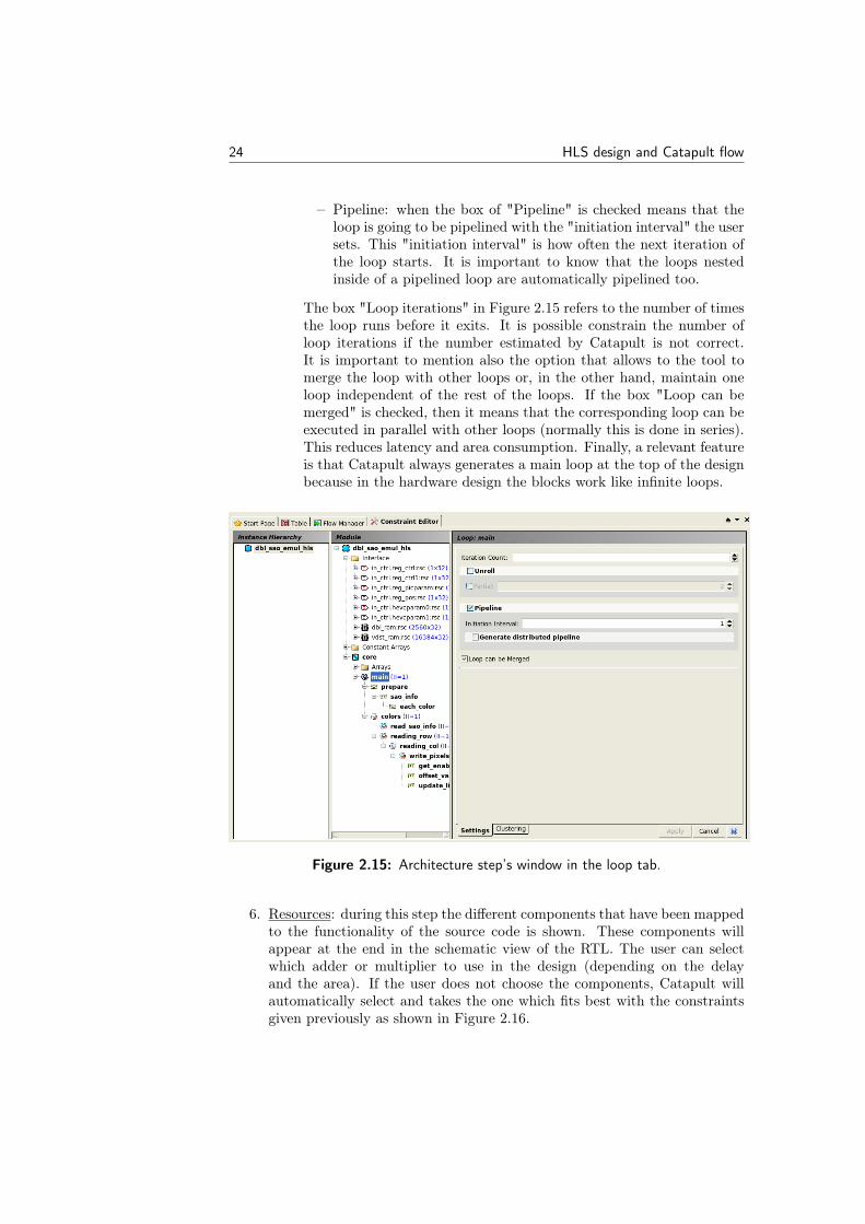
– Pipeline: when the box of "Pipeline" is checked means that theloop is going to be pipelined with the "initiation interval" the usersets. This "initiation interval" is how often the next iteration ofthe loop starts. It is important to know that the loops nestedinside of a pipelined loop are automatically pipelined too.
The box "Loop iterations" in Figure 2.15 refers to the number of timesthe loop runs before it exits. It is possible constrain the number ofloop iterations if the number estimated by Catapult is not correct.It is important to mention also the option that allows to the tool tomerge the loop with other loops or, in the other hand, maintain oneloop independent of the rest of the loops. If the box "Loop can bemerged" is checked, then it means that the corresponding loop can beexecuted in parallel with other loops (normally this is done in series).This reduces latency and area consumption. Finally, a relevant featureis that Catapult always generates a main loop at the top of the designbecause in the hardware design the blocks work like infinite loops.
Figure 2.15: Architecture step’s window in the loop tab.
6. Resources: during this step the different components that have been mappedto the functionality of the source code is shown. These components willappear at the end in the schematic view of the RTL. The user can selectwhich adder or multiplier to use in the design (depending on the delayand the area). If the user does not choose the components, Catapult willautomatically select and takes the one which fits best with the constraintsgiven previously as shown in Figure 2.16.

HLS design and Catapult flow 25
Figure 2.16: Dialog of the Resources step.
7. Schedule: at this point the user can check how the functionality of thesource code has been translated from an untimed to timed and how it hasbeen assigned to each clock cycle a part of the C code. It can be also checkedwhich loops that consume more execution time. The tool allows the userto change the schedule, moving the different operations to different clockcycles. However, the limitation is for example, one operation that its resultis the input of another operation can not be moved to a later time than thebeginning of the operation depending on it. This limitations are highlightedas red marks shown in Figure 2.17. The figure shows all the operations onthe left side sorted by timing execution. If double-clicking on the operationit will show which is the corresponding piece of code. The drawbach is thatthe user can not see the pipeline stages in a clear way and this makes itdifficult to check where the pipeline stages have been placed in the design.

26 HLS design and Catapult flow
Figure 2.17: Schedule dialog.
8. RTL: This is the last step, when the Verilog and the VHDL code is gen-erated. The user can access the codes but they are almost unreadable.TheRTL diagram is also generated in this step. In the RTL diagram the user cansee the data path, the components and resources used in the design, areaand timing information and schematic view of the RTL. The Figure 2.18you can see an example of a schematic view of a generated RTL.
2.2.2 Output files
Once the RTL is generated, Catapult provides the user with some useful informa-tion to show how the design has been implemented in hardware.
The user can find these files in the Output Files folder generated by Catapultin the working directory. Some of the information given in these files is:
• Schedule: Catapult provides the user with a schema about how the opera-tions are scheduled in the design and in which clock cycle the operations areplaced. This information can show the user where the pipeline stages areplaced in the design and which are the operations that consume more timeand increase the latency. If the design has more than one block, this schemaalso shows the user which blocks are the ones which needs more time ofexecution to finish its defined functionality. An example of schema is shown

HLS design and Catapult flow 27
Figure 2.18: Schematic view of an RTL.
in the Figure 2.17 and has already been described in the section 2.2.1 whenexplaining the schedule step.
• Schematic -> RTL: Catapult also gives an architecture schematic view ofthe generated RLT where all the operations are included and it shows howthey are connected. This schema also shows the memories even when theyare not included in the design to give the user a better understanding.The user can see the FIFO pipes generated by the channels and the addedregisters to perform the pipeline stages. It displays critical paths and pathtiming data that can be really useful for understanding how the design ismade. An example of this is shown in the Figure 2.18.
• Schematic -> Critical path: Catapult finds the critical paths of the designand the paths limiting the clock frequency of the design. The user can seethe critical path reflected in the RTL schematic.
• Reports -> RTL: This report gives the information about the resources usedin the design and useful information of how the design has been character-ized. The information given is the timing, latency and throughput of thedesign, the bill of materials, the area score of each type of elements, howthe registers are mapped, a timing report... and other useful information.
2.2.3 Verification
Catapult allows the user to create a unique testbench for verification for both, theC code and the generated HDL code. This is a very useful feature since after theLibrary step, when the compilation of the C code has been done, Catapult givesthe possibility to run a testbench to test the behavior of the C program. Testingthe functionality of the design described in C before starting the generation of the

28 HLS design and Catapult flow
RTL, is very useful because the user can test if the source code has been developedcorrectly and if the functionality is the one expected. These are the basic stepsto be checked before starting to generate the RTL, else it will not describe thecorrect functionality in hardware.
After running the complete process in Catapult, and after the tool has gener-ated RTL, Catapult provides the user with an RTL simulation. Both mentionedsimulations can be shown in the Figure 2.19. In the folder Verification, thereare two folders: gcc folder for C simulation and Modelsim [10] folder for RTLsimulation.
Figure 2.19: Verification files for C and RTL simulation.
The RTL testbench is basically the same test as the test written previously forthe C program. Catapult compares the results from the C code and the results fromthe HDL code and if they match, then it has been correctly generated. AlthoughCatapult is not testing specifically the functionality of the RTL, if the functionalityin C is correct, then if this comparison passes, it also means that RTL has thesame functionality.
The comparison done by Catapult is explained in the Figure 2.20. The driversprepare the input data that the testbench gives to the C code and make it suitablefor the RTL code and then they take the output data coming from the RTL, andcompare it with the output data coming from the C. Catapult does not only checkif the result is correct, Catapult also checks if they are coming in the right order.To make this verification possible, it is necessary to enable the option of SCVerifythat Catapult has before the execution starts.
Another advantage of this verification in Catapult is when the tool runs thesimulation of the RTL in Modelsim. The test shows some useful signals in thewave window to highlight the detection of an error. The waveform shows the

HLS design and Catapult flow 29
Figure 2.20: Catapult verification process.
input and output signals, signals that indicates when each block is being used,when the system is running or stalled. These signals give very useful informationto understand where errors are coming from and it helps to know where the usershould look in the code or in the architecture constrains.
During this work we have done two different simulations to compare the be-havior of the developed systems. The first simulation that has been done is withthe testbench we have written in Catapult, like a first verification of the systemalthough it has low test coverage. The second verification process has been donein the ARM flow, to get the same test coverage as any other ARM block. Wehave verified the code in two ways because during the first verification we couldfind the majority of the errors and once the first verification was working, usuallythe verification with ARM test also works. In the ARM flow we have done theverification of the RTL and the C code.
Verification in Catapult
The process is divided in three parts:
• Catapult runs the C verification using the testbench to get the referenceresult.
• Catapult runs the RTL simulation with the same data as the testbenchdeveloped for the C code. The inputs given by the testbench are able to

30 HLS design and Catapult flow
reach the RTL code through drivers as already mentioned. Catapult getsthe output data of the RTL when the simulation is finished.
• Catapult compares the result of the C verification and the RTL simulation.If the comparison gives the same results the test passes and it means thatthere is a high probability of having a correct behaving RTL.
To make a correct comparison between the C code and the RTL for the sys-tems we have worked with, we have tried to get the same input signals from filesthat were used to test the handwritten RTL. For example, when a system or blockinvolves memories, files were given to the testbench that contains the initial andfinal of the memories. These contents are the real possible values for which thesystems or blocks have been designed for. So with these files, the testbench intro-duce known data to the system with its corresponding correct output. For eachblock we have developed multiple tests to check the behavior in different situa-tions. This kind of test runs really fast under Catapult execution thus we can runthem until obtain a good coverage result.
Although Catapult provides the user with this useful feature to test the C codeand the RTL code, it is necessary to add some code lines in the testbench to makeit possible:
• Add the SCVerify header to the testbench code, "#include mc_scverify.h".
• Use CSS_MAIN macro instead of the function main. This change allowsCatapult to go through the simulation in HDL correctly.
• Wrap the call of the top level function with the CSS_DESIGN macro.
• Change the command return to CSS_RETURN, which allows Catapult toreturn an error in HDL if necessary.
Verification in ARM’s flow
The verification we do in ARM’s verification flow gives a better test coverage thanthe previous one but also takes longer time. This is why we have only run ARM’sverification when the previous one was already working as expected, to minimizethe quantity of errors to solve.
The ARM’s verification flow checks at the same time the behavior of theRTL and of the C code with many different inputs and control signals includingsituations that touch all the corners of the system and its boundaries. If thebehavior of the HLS C code is the same as the behavior of the handwritten RTLit is sure that the functionality of both systems are the same.
We also run another test in the ARM’s flow. We run the reference C modelat the same time as the RTL generated by Catapult to check also if both codeshave the same behavior. With this two verification process described before, allthe blocks or systems we have been working with, has been tested with high testcoverage.

HLS design and Catapult flow 31
2.2.4 Synthesis
After writing the C code in Catapult and generating the RTL, the next step (tofinish with the characterization of the system that Catapult offers) is to run thesynthesis of the RTL. Running the synthesis, apart from giving us post-synthesisarea and timing results, it also generates the netlist of the design and the netlistis the source to calculate the power consumption. The power has not been one ofthe objectives of this thesis but we can make some assumptions based on the clockfrequency, the area and the bill of materials.
During this thesis work, we have run the synthesis in two different ways. Theone most used has been the synthesis with Catapult that gives the possibility aftergenerating the RTL to run the synthesis with DesignCompiler [11]. This is thefastest way to do it because it is done automatically without having to defineany option, obtaining correct results of area and timing of the design. We havealso run the synthesis in ARM’s flow like ARM does normally with its designs.Synthesizing the design in ARM’s flow has some advantages which are explainedin the following sections.
Synthesis in Catapult
The synthesis in Catapult is done through the tool DesignCompiler. Catapult pro-vides the user with scripts to run the synthesis and obtain post-synthesis area andtiming information of the designs. Having this functionality inside the Catapultinterface is useful because without leaving the tool, the user is able to create acomplete design from C source code to netlist.
It is not necessary to do any previous steps before running synthesis or giveany parameters to the tool. Catapult is responsible to give the DesignCompilerthe RTL code and also the constraints needed, for example the system clock.This is very useful to obtain a better estimation of the area of the design. Asmentioned before, Catapult is always overestimating the values of area score andunderestimating slack when it is generating the RTL. For this reason, running thesynthesis is very important to have a better estimation of the area and also tocheck if there are any timing violations.
The results of area given by the synthesis in Catapult are the results we haveused to compare with, because it is a very fast estimation of the area with a highprecision. Although it is a fast execution, this is the step that takes more timecomparing with the RTL. The run time depends on the size of the design: largerdesign, longer time.
Synthesis in ARM’s flow
Although the synthesis can be run in Catapult, make it in the ARM’s synthesisflow is important to have two different point of view and also for evaluating ifthe result obtained in Catapult synthesis is correct. It has been checked thatboth synthesis results are similar and this is why the synthesis of Catapult has
32 HLS design and Catapult flow
been used during development. When the synthesis is done in the ARM’s flow,the same constraints as the ones applied to the original design have been applied.Also, when running the synthesis in ARM’s flow, it generates reports where allinformation is collected in the timing report or the violations constraints reports.The user can check which are the paths that violate timing (setup time or holdtime).
The most important use of the synthesis in the ARM’s flow has been forobtaining the area values of the handwritten RTLs which we have compared withour generated RTL. The user can get easily from the synthesis the area report,where the area of each block that is implemented in the design is described. Itscombinational and sequential area also appears. This has been useful for improvingthe generated RTL by Catapult, because it was known where the area differenceswere situated.
2.3 Catapult Library Builder
The evaluation license we have from Catapult comes with a standard library char-acterized by Catapult. It is a very important step to characterize the target librarythat is going to be used in the synthesis step. When Catapult generates an RTLcode, the scheduler is giving latency and throughput results with the constraintsdefined but also with the information taken from the libraries. If the target libraryused for the synthesis step is not the same as the one used for the RTL generationin Catapult, the best result in terms of latency, throughput and area will not beobtained and the RTL generated is going to lose precision and quality. This hap-pens because if the target library is not used for the RTL generation, for example,in the schedule and resource steps, Catapult is doing in an inefficient way theselection of the components and its scheduling because it has not the informationof the characterized cells from the target library.
2.3.1 Cell Library
To characterize a library for Catapult, the license given by Calypto provides an-other tool, "Library Builder". With this tool, Catapult is able to characterize allthe library cells from a .lib file and a .db file of the target library. It is necessaryto also give Library Builder some constraints and information about the library,to be able to make a good characterization for Catapult and correct generation ofRTL.
For the characterization of the cells, Catapult takes each cell that is in theoriginal library and runs it with DesignCompiler to get area and delay information.
As shown in Figure 4.1, that is an example of the principal window of LibraryBuilder program, all the components from the original library are listed on theleft side. For example, the first component that is shown is the inverter, andinside it there are two cells defined, the inverter with 1 and 8 bits respectively. Inaddition, each of the mentioned cells that is going to be characterized in different

HLS design and Catapult flow 33
Figure 2.21: Catapult library builder window.
points can also be seen. During the characterization process, Catapult LibraryBuilder collects multiple sets of characterization data (area and timing) for eachcell. The cells, by default, have 4 characterizations each: the fastest (100%), 75%,50% and the smallest (0%). If the user wants to add or delete some points of thecharacterization, it is possible to set this in the options.
The characterization process works as follows for each component:
1. Get the fastest data set and run DesignCompiler with the target delay spec-ified for the fastest clock frequency.
2. Get smallest data set and run DesignCompiler with the target delay specifiedfor the smallest clock period.
3. Get each intermediate data set. Use the values obtained from the fastestand smallest characterizations to calculate the delay which is going to beused in the intermediate characterizations. Then run DesignCompiler againfor each intermediate point. Intermediate points are specified by the ClockPeriod Percentages setting.
When the Ultra Mode option is selected the characterization of the librarytakes around one week to finish and if the Ultra Mode is not selected, the char-acterization takes less than one day. Although it takes more time, with the UltraMode selected, the library characterized gives better results.
It is very important to select the Wire Load Mode to zero, because if notthe characterization of the library creates an overly pessimistic Catapult library.These tips are in the Catapult C online help.

34 HLS design and Catapult flow
2.3.2 Memory libraries
Even when the design does not include memories (only the interface) inside it, thememory libraries characterization should be done, to allow Catapult to create theinterface of the memory with the necessary information about it.
This characterization is done with Catapult (not with another extra tool) inthe library step. As it was shown in Figure 2.7, it exists a button called "MemoryGenerator" and is where the memory characterization is done. To be generated,Catapult needs the RTL description of the memory, which kind of memory is goingto be implemented (single port memory, double port memory...) and needs alsoto know how the pins of the memory are connected.
If the memories are not going to be included in the design a deeper character-ization should not be performed.

Chapter3Reference Designs
This section contains a brief description of the video blocks and designs we havebeen working with during the project. The C model and the handwritten RTLwere given for this HLS study, therefore knowledge about how to implement thealgorithms was not completely necessary.
Before starting to explain the functionality of each filter, it should be describedwhat de-blocking filter (DBL filter) means, because all modules we have beenworking with are DBL related. A de-blocking filter is a video filter used in decodingand encoding of video to improve visual quality and prediction performance. Thisis done by filtering the edges between the macro-blocks that compound a videoframe. The filter should improve the appearance of decoded pictures[12].
This chapter is divided in two sections:
• Simple blocks: blocks which have no sub-blocks inside them, this means thatthey are not compounded with other sub-blocks and they do not implementany communication protocol as channels inside them.
• Complex blocks: blocks which are compounded by two or more sub-blocks.The sub-blocks need communication between them and can be implementedas hierarchical blocks, CCOREs or as a flat design.
All the blocks developed during this work are involved in a filtering process ofvideo signals as shown in Figure 3.1.
Figure 3.1 describes three types of blocks:
• Controller blocks: these are the blocks located to the left in the figure. Theytake the control data coming from a video signal and prepare it for the filter.One of the developed complex blocks is in this group.
• Filters: these are the filter cores. We have developed some of them as simpleblocks. They are located in the center of the figure.
• SAO block: these blocks are located to the right in the figure and they filteragain the signals coming from the filter cores. The other developed complexblock is in this group.
35

36 Reference Designs
Figure 3.1: Schema of the filtering process where are included thestudied blocks
3.1 Simple blocks
In this section is explained the behavior and the characteristics of some simpleblocks we have developed. Some of them are filter cores and the rest are sub-blocks of the complex blocks.
3.1.1 DBL filter H.264
The H.264 filter appears in both paths in a system, the decoding path and theencoding path. This feature makes that the in-loop effects of the filter are takeninto account in reference macro-blocks used for prediction. While encoding, thefilter strength can be selected. If the filter is not switched off, the filter strength isdetermined with techniques that use the adjacent blocks, quantization step size,and the steepness of the luminance gradient between blocks.
This filter operates with 4x4 or 8x8 transform block in the luma and chromaplanes. For each edge of a small block, is assigned a boundary strength based onif it is also a macroblock boundary, the coding of the block, and if it is a lumaor chroma edge. Where there are more probability to have a higher distortion, ahigher strength of filter is applied. In most cases the filter can modify one or two

Reference Designs 37
samples on either side of the edge and in some particular cases it can modify eventhree samples[12].
3.1.2 DBL filter HEVC
The High Efficiency Video Coding standard (HEVC) is one of the most recent videoprojects of the ITU-T VCEG and ISO/IEC MPEG standardization organizations.In comparison with the H.264, HEVC aims to reduce around 50% bit rate underthe same visual quality [13].
The HEVC standard uses two different coding schemes, the block-based pre-diction and the transform coding. The size of the blocks for both coding schemecan vary from 4x4 to 64x64. This standard may produce blocking artifacts in theblock boundaries. These artifacts are produced because the algorithm does notfully consider the correlation between adjacent blocks.
In HEVC the de-blocking filter has been designed to reduce or eliminate com-pletely the artifacts in the block boundaries [14].
3.1.3 DBL filter Real
The purpose of the real video filter we have studied during the Master’s Thesis,is to filter the edge between two 4x4 blocks, using the same algorithm for thevertical and the horizontal edges. To decide which edges should be filtered, ituses the motion vector and the transform block mask in the same way as in H.264.Each block is filtered horizontally and vertically before going to the next 4x4 block.Depending on the block activity, the type of the filter is determined. There arethree types of filter: strong, normal and weak.
3.2 Complex blocks
In this section is explained the behavior of each complex block, including theirsub-blocks. We have developed two complex blocks the DBL SAO and the HEVCController block
3.2.1 DBL SAO
The SAO filter is the Sample Adaptive Offset filter used in HEVC. It is located afterthe de-blocking filter. The main purpose of this filter is to reduce the distortionbetween the original samples and the final samples (reconstructed). With the SAOfilter, the video compression can be improved in both, objective and subjectivemeasures [15]. This is done compensating the distortion between the original videoand the reconstructed video during the encoding process [16]. The SAO filter wasdesigned to increase picture quality, reduce banding artifacts, and reduce ringingartifacts [17].

38 Reference Designs
This filter applies offsets that are located in a lookup table in the bit stream.It has two modes: edge offset mode or band offset mode. The edge offset modecompares the value of a sample with two of its pixel neighbors using directionalgradient patterns. Then the samples can be classified in five categories: minimum,maximum, edge with the lower sample value, edge with the higher sample valueand monotonic. If the sample is in one of the four first categories, then an offsetis applied[17] [18].
The band offset mode checks the amplitude of a single sample and applies anoffset based on it. There are 32 bands where the sample can be categorized by itsamplitude. Only for four consecutive bands the offset is specified, because sampleamplitudes tend to be clustered in a small range in flat areas (they are prone tobanding artifacts) [17] [18].
3.2.2 HEVC Controller block
This block is responsible for parsing control data from FIFO pipes and providesit to the filter cores. It reads the parameters from FIFOs and prepares the datain the correct format to give to the filter. It is compounded by 5 blocks:
• PU parameters parser: it reads prediction units of various size from a FIFOand places them in registers.
• TU parameters parser: it reads also transform units of various size from aFIFO and stores them in registers.
• Boundary strength block: with the data from the PU parameter parser, itgenerates boundary strength values for the filter.
• Edge QP parameters block: with the data from both input blocks, it gen-erates edge flags and QP values.
• Controller block: it is the responsible for connecting all the sub-blocks,and processing all the prediction units to generate filter and SAO controlinformation.

Chapter4Implementation
In this section we are going to explain the development of simple and complexblocks. The development of each block is described as well as the improvementsdone and the problems we have found with the tool. Every section in this chapteris divided in simple blocks (filter cores only compound by one block each) andcomplex blocks. The complex blocks are DBL SAO, where is explained how wehave developed the larger de-blocking SAO filter compounded by more than oneblock with communication between them, and the HEVC controller block whereis described how we have developed this complex block once we have understoodmore Catapult.
4.1 Development of simple blocks
During the first part, we have being working with some simple blocks to familiarizewith the tool and learn all the specifications and rules we should follow to developa design in Catapult. To do this we have been provided with some simple blocksthat the RTL had been developed previously in Verilog, to compare the resultswith the RTL generated by Catapult.
All the designs we have tested during this step consist of simple blocks (thereis no communication between blocks) that receives one or more pixels and severalcontrol signals and produces one or more pixels. All the blocks have been im-plemented as Design blocks. In the first design we have implemented handshakecommunication in the interface, which means that the input and output interfacehave been implemented as channels for all blocks. To evaluate these simple blockswe have used ARM libraries for RTL generation.
For making the first implementation we have declared all the inputs and out-puts of the system as channels and modify them to be bit accurate. To get a highquality RTL is very important to define the interface as close as possible to thehandwritten RTL. Frequently one channel for the input pixels, other channel forthe control signals and the last channel for the output signals are created in theblocks.
39

40 Implementation
The main problem we faced during this part has been the area score, becausewe achieved more area score than the handwritten RTL. It is very important toget similar area score with Catapult for making it useful in ARM’s flow, as well assame functionality, latency and throughput. To discover why our implementationis implying a big difference in area, we have analyzed all the blocks we have studiedto find a common point between them and be able to solve the problem.
The blocks we have analyzed in this part are:
• SAO filter core.
• De-blocking Real filter core.
• De-blocking HEVC filter core.
• De-blocking controller HEVC sub-block edge QP parameters.
• De-blocking controller HEVC sub-block boundary strength calculation.
One of the blocks we have developed separately is the filter core of the DBLSAO design. This filter is included in the DBL SAO block. It was important thedevelopment of this block because is one of the simpler blocks, thus is very easyto find the differences between the original handwritten RTL and the HLS RTL.
In the case of the DBL SAO filter core, with an implementation like the onedescribed previously, with channels in the interface, we got twice the area for thesame operating frequency. This was not a good result, but then we started toinvestigate where the area in our design was originated.
The throughput and the latency were the first parameters that were checked.The latency had one more cycle than the handwritten RTL therefore we decided toimprove the code as much as we could and also the micro architecture constraintsto get one clock cycle less of latency to obtain the same characteristics.
Once we got it, we knew that both systems had the same pipeline stages. How-ever this was not the problem of the area, because we were still having more area.We continued investigating the HLS design, checking the number of componentslike adders or subtractors used by the design.
Although the operators were not exactly the same, both designs used a similarnumber of them, and the functionality was the same, therefore we thought theproblem did not come from the combinational process.
When we checked the area reports that the synthesis process create, we noticedthat the sequential area was bigger in the HLS design (always more than 150%compared with the original) but the combinational area was +/- 25%. With thisconclusion in the filter core of the DBL SAO, we started to develop the rest of theblocks that ARM gave to us. We always followed the same steps:
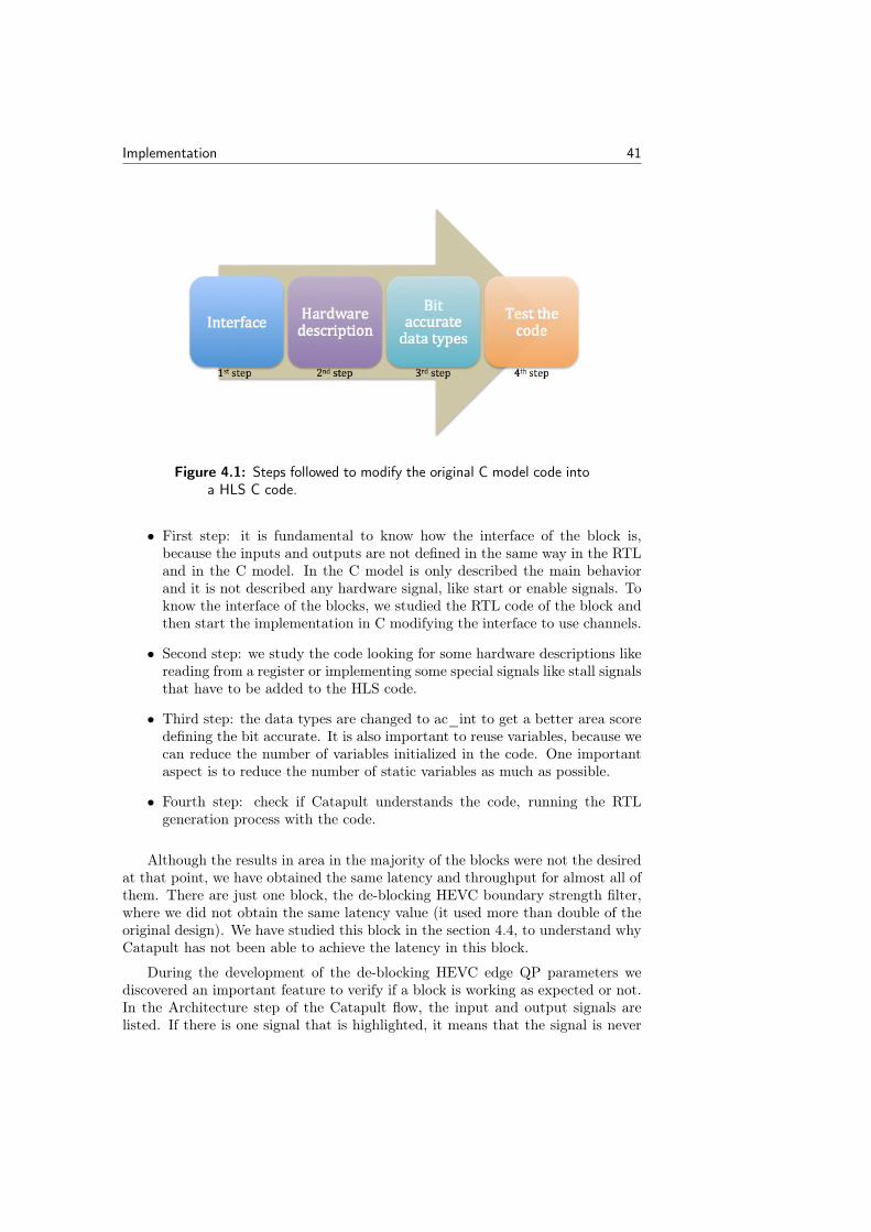
Implementation 41
Figure 4.1: Steps followed to modify the original C model code intoa HLS C code.
• First step: it is fundamental to know how the interface of the block is,because the inputs and outputs are not defined in the same way in the RTLand in the C model. In the C model is only described the main behaviorand it is not described any hardware signal, like start or enable signals. Toknow the interface of the blocks, we studied the RTL code of the block andthen start the implementation in C modifying the interface to use channels.
• Second step: we study the code looking for some hardware descriptions likereading from a register or implementing some special signals like stall signalsthat have to be added to the HLS code.
• Third step: the data types are changed to ac_int to get a better area scoredefining the bit accurate. It is also important to reuse variables, because wecan reduce the number of variables initialized in the code. One importantaspect is to reduce the number of static variables as much as possible.
• Fourth step: check if Catapult understands the code, running the RTLgeneration process with the code.
Although the results in area in the majority of the blocks were not the desiredat that point, we have obtained the same latency and throughput for almost all ofthem. There are just one block, the de-blocking HEVC boundary strength filter,where we did not obtain the same latency value (it used more than double of theoriginal design). We have studied this block in the section 4.4, to understand whyCatapult has not been able to achieve the latency in this block.
During the development of the de-blocking HEVC edge QP parameters wediscovered an important feature to verify if a block is working as expected or not.In the Architecture step of the Catapult flow, the input and output signals arelisted. If there is one signal that is highlighted, it means that the signal is never

42 Implementation
used in the code, and the reason for this is that the interface is not defined properlyor the code is not working as expected.
In the DBL HEVC edge QP parameters, we knew that the interface was definedcorrectly, so the problem was that the HLS C code was not understanding properlythe code. We checked the code and discovered that there was one function definedin the C model developed in ARM that works for int types but not for ac_inttypes. This function allows the user to get some bits from a signal, therefore toavoid its use we have substituted with the slc method provided with the ac_inttypes. The method is used in many blocks developed during this Master’s Thesisso we have had to avoid the use of this function in all the block where it appeared.
4.2 Development of DBL SAO
To test the quality of the RTL generated by Catapult, ARM provided us with twolarger blocks than the previous ones which had been generated before by them,to compare the final results of original RTL with the HLS. In this section we willdescribe the development of one of them, the DBL SAO. They also gave to us theC model of the blocks and with some slides to understand how is the behavior ofthe design and how they had developed the architecture.
The C model developed to check the behavior of the design was written withoutany hardware description, it was written like a software code. This means, forexample, that the line buffer block was not described in the model, because thenumber of times the blocks read or write in the memory is not important for thebehavior of the design.
To develop the DBL SAO have been followed some steps to reach the bestsolution in terms of area:
• Develop the architecture: With the architectural description of the design wedrew a simple architecture schema to be sure how the design was partitionedthat we were going to develop in HLS. This step gives the developer a generalidea of the blocks that should be developed in the system. Each of theseblocks will be a function in the C code. The functionality of them can changeduring the development of the code, but the main idea should be maintained.These blocks or functions are the ones which give the functionality to thewhole system. The architecture of the design has been redesigned duringthis work to reach the best solution with the same behavior as the originalRTL, but the functionality of each block has not changed.
• Data-path: Once the blocks that were going to be implemented was selected,the next step was to create the sub-blocks only with the interfaces, definethe data-path without functionality and connect them to implement thecommunication of the system.
This should be done before giving the functionality to the blocks, to be surethat each module has the necessary signals to connect with the rest and

Implementation 43
receive data from the input wires or assign data to the output wires. Weimplemented a bypass system.This method is useful at the beginning because the user can understand howthe blocks should be connected and how the intermediate channels work. Itis also important to check that all the signals in the design are availablewhen they are needed. The synchronization between the control signalsand the other signals must be exact. The type ac_channel simplifies thesynchronization of the system.
• Functionality: when we had the interconnection of the blocks implemented,then the functionality had to be described but without modifying the con-nections between the blocks. In our case the functionality had been de-scribed in the same way as it is done in the C model, but dividing theoperations and the algorithms between the blocks. We also implementedthe non-software parts of the design like the line buffer. The functionalityof this module was not defined in the C model because it is not useful totest the behavior of the DBL SAO. We have modified some operations toget less registers and operators when the RTL is generated.
• Verification in Catapult: the next step is to verify if the code is functionallycorrect. To do this, it is necessary to write a C testbench where the func-tionality of the design is tested. This testbench will be valid for the C codeand also for the generated RTL as explained in the section 2.2.3.The testbench has to test the C code before generating the RTL, to see ifthe source code is working as expected. After the generation of the RTL,the output of the C code is compared with the output of the RTL generatedto check if the behavior of C and RTL are the same.Once the C model is working, the next step is to create the RTL in Catapultwith the same micro architectural constraints as the original design. We willobtain a first approximation of timing and area score in Catapult. The areascore that Catapult gives after the RTL generation is usually bigger thanthe area score after synthesis. When the RTL is generated the testbenchwritten previously is run in Modelsim, and compared with the results givenby the RTL. When the RTL has the same behavior as the C code, the testpass. To verify the C code and the RTL with a good test coverage, onceit had been developed and tested in Catapult, we added it to the ARMverification flow.
• Synthesis: the last step is to generate the netlist of the design with theRTL generated by Catapult and compare timing and area with the originaldesign. This is also done in Catapult with the software DesignCompiler.
4.2.1 Structure development
In the C model provided by ARM there is one main function where the func-tionality of the system is described. However in HLS we need to develop onefunction for each block we want to implement with hierarchy or as a CCORE and

44 Implementation
it is also needed another block to connect them (the top level function). Eachblock/function described makes a specific function, as a hardware sub-block, togive the final functionality to the complete design. As described previously, wefirst started drawing the architecture in a very general way with the help of thearchitecture description given. When all the blocks has a well defined function andthe communication between them is correct, then we can start coding the blocksas described below.
Figure 4.2: Schematic view of the DBL SAO architecture.
In our case we have divided the system in five blocks, the function names aregeneral and the functionality is described deeply in the code.
• Read: this block is responsible for reading values from memory and givethem to the rest of the blocks. The read memory is not included insidethe design, as described in section 2.1.3, and the tool generates the memoryinterface automatically.This is the only block in the design that reads from the memory, thus it isnecessary to give it all the addresses to get the input pixels and the inputcontrol data from the memory. Two or more blocks are not allowed to readfrom the same memory, to do this an arbiter should be implemented. Insteadit reads both, the input pixels and the control data used by the rest of theblocks first and then send them through channels.
• Line buffer: this is the block that is not defined in the original model. Itwas not developed because in the C model the non-software modules do nothave to be described. Thus it does not care about how many times the codeaccesses the memory or for how long the program is executed. However inCatapult it is completely necessary to describe this kind of blocks, if we wantthe generated RTL to have the same behavior as described in the original

Implementation 45
RTL. The purpose of this block is avoid multiple read of the same addressfrom the same memory. With the implementation of this block in the design,it decreases the memory accesses because only it is necessary one access tothe memory for each address and the operations are done more effective.
This line buffer stores two line of pixels (36 pixels), while the third line isbeing received. The block is able to send the data required to the next blockand then overwrite the pixels that would not be used any more to store theone coming in the input. It is described with some hardware details becausethis kind of module must be described with many details if the user wantsto obtain the same implementation as in the handwritten code.
• Filter: this block is the one that performs the filtering operation. This filterhas been developed previously as a simple block. The original C code writtenfor this block has been modified to be more efficient for RTL generation, forexample, we have written the code thinking in hardware style coding toreduce the number of variables used or reduce the complexity of some of theoperations.
• Write: the write block performs the write operations of the block. Like inthe read block, the interface is generated automatically by the tool, becausethe memory is not included inside the system. This block is also responsiblefor calculating the destination address for the output.
• Control: the control block receives the input from outside and then is theresponsible to give to each block the control signals they need. This blockhas been divided in two blocks to avoid the bidirectional communication withchannels between two blocks (this problem is explained in the section 4.7.3).The block receives through the input interface some control signals, andgives the information to the read block to obtain from the memory all theinformation needed in the system. The second part of the control blockreceives data from the read block and gives these data to the filter and thewrite block.
4.2.2 Constraints Set
One important aspect in the system design is to make a good comparison betweenthe system developed in a standard way and the system developed in Catapult isthat both systems must have the same characteristics in terms of latency, area andthroughput. It is very important to try to reach the same characteristics in bothsystems, because, if we for example get more latency, that means the system needsanother pipeline stage to get the same throughput and an additional pipeline stagein the system means more registers in the system implementation.
We want to be sure we get the same results in all the blocks that are part ofthe DBL SAO, thus we decided to implement and generate the RTL separatelyfor each sub-block and then, in a final step, join all in the same system. We haveused a bottom up generation in Catapult. For each block we have studied thelatency, the throughput and the bill of materials. Once we got a similar solution

46 Implementation
to the original in all the blocks, we have implement a top block of the system thatconnects all of them.
As previously explained, Catapult is not reporting the throughput as expectedbecause it is measuring in other terms. Therefore during the verification processin Modelsim, with the help of the waveform we checked the throughput of thesignals to verify that the system was working as expected.
To get the same value of latency and throughput as the handwritten code wehave pipelined all the loops with an initiation intervals of one for all, to be able toget an input to each block in each clock cycle. We have also unrolled some of theloops to reach a better solution in terms of latency. The loops we have unrolledin the systems are loops that do not have access to memory or write or read froma channel. Like in standard RTL, Catapult does not allow the user to access achannel or a memory more than once to in the same clock cycle.
During the resource step we have not set any specific component for the op-erations, because Catapult selects the ones which fit better with the constraintsgiven during the Architecture step.
4.3 Development of the HEVC Controller Block
After implementing DBL SAO and having more knowledge about Catapult, to getmore reliable results in terms of design’s quality, we developed another "complex"block with five different sub-blocks. This block is the HEVC controller block andthe C model has been developed by ARM. The block are compounded by threetypes of blocks:
• Input blocks: there are two blocks that read input signals from a FIFO.To implement this kind of reading process we have used ac_channel type,because there is not another way to implement a read process from a FIFOpipe in Catapult.
• Output blocks: these two blocks receive data from the controller and theinput blocks and generate the outputs. These outputs are not defined aschannels.
• Top block: this block is the controller. It has been implemented like the topblock because it calls the rest of the functions. It connects the sub-blocksbetween them and reads also from memory and write to memory.
One of the important aspects that were studied with the development of thisblock, is the time HLS can save in comparison with the traditional hardwaredesign. We know how long time ARM took to develop the C model, and also howlong time we spent developing it for HLS, therefore we know how much time wespent in the process. The time spent in the project would not be the same if theC model is developed for HLS from the beginning, because we have spent timeimproving the system to get a better solution.
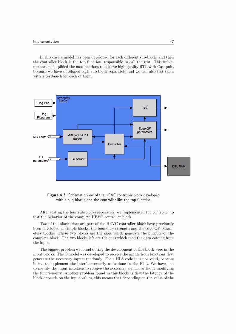
Implementation 47
In this case a model has been developed for each different sub-block, and thenthe controller block is the top function, responsible to call the rest. This imple-mentation simplified the modifications to achieve high quality RTL with Catapult,because we have developed each sub-block separately and we can also test themwith a testbench for each of them.
Figure 4.3: Schematic view of the HEVC controller block developedwith 4 sub-blocks and the controller like the top function.
After testing the four sub-blocks separately, we implemented the controller totest the behavior of the complete HEVC controller block.
Two of the blocks that are part of the HEVC controller block have previouslybeen developed as simple blocks, the boundary strength and the edge QP param-eters blocks. These two blocks are the ones which generate the outputs of thecomplete block. The two blocks left are the ones which read the data coming fromthe input.
The biggest problem we found during the development of this block were in theinput blocks. The C model was developed to receive the inputs from functions thatgenerate the necessary inputs randomly. For a HLS code it is not valid, becauseit has to implement the interface exactly as is done in the RTL. We have hadto modify the input interface to receive the necessary signals, without modifyingthe functionality. Another problem found in this block, is that the latency of theblock depends on the input values, this means that depending on the value of the

48 Implementation
inputs, the block reads more or less values from the input FIFO pipe.
To implement a FIFO pipe in the input of a block,it is necessary to implementthe type ac_channel explained in the section 2.1.1, because it is necessary toperform one access to the same FIFO pipe each cycle. Implementing a channelproduces some disadvantages in the block because it sometimes generates morelogic than the necessary. This makes the final area score, before making anyrefinement of the code larger than the expected.
To get a correct value, similar to the handwritten RTL’s area score we havemade refinements to the code.
Although in Figure 4.3 the controller appears as another sub-block, it is im-plemented as the top function. It controls which signals are sent to the sub-blocksand when each block is executed.
4.4 Refinement of simple blocks
Once we developed all the new blocks, we began to investigate in the same wayas we have done before with the filter core of DBL SAO. The results we obtainedwere very similar to the results given by the DBL SAO filter core, we noticed thatthe sequential area in HLS RTL is always bigger than the sequential area of thehandwritten RTL.
The HLS design was generating more registers than necessaries in the systemand this was producing a huge increase in area. The problem of the increasedsequential area can come from different sources, for example:
• Different number of pipeline stages: this was one of the errors we have toface during the area issue investigation. When the blocks were given tous, we did not know any information about timing and we developed theblocks with the latency and the throughput we though can be the correct.If a system is compared with another that does not have the same timingconstraints like latency or throughput the comparison is not valid, becausethe number of registers can change, for example if the pipeline stages are notthe same. Therefore we first got the necessary information to know whichare the characteristics of each block, to have a good comparison referencebefore making any conclusions.
• Generation of input register: this was also one important error in the major-ity of the designs. As the Catapult training explained, we used ac_channeltypes for all the interfaces, because it simplifies the communication betweenblocks, and gives the user the possibility to easily implement a hand-shakecommunication. This communication brings with it some problems, that wehave explained previously in this report (section 2.1.1), like for example thegeneration of FIFO pipe between two blocks, and also it generates some reg-isters inside the blocks that sometimes increase in a large quantity the areascore. The solution to this problem is to avoid the use of ac_channels in the

Implementation 49
interface but this also complicates the implementation of the communicationbetween the blocks.
• Wrong placement of the pipeline stages: this mismatch not always generatesmore area, but if we want to compare the same designs it is important tohave the same number of pipeline stages and placement, because the widthof the registers depends on the location of the registers. From our point ofview a correct comparison is made with exactly the same pipeline stages inthe design.
The main problem in all our blocks is coming from the registers (input andintermediate registers) generated by Catapult in the designs. In these blocks,the registers that are more significant in the area used, are the input registers,because they are simple blocks with a large amount of bits in the input interface(data input and control signals). This problem is obvious in the DBL SAO filtercore. With the channel interface implementation, an input register appears thattook the same area score as all the sequential part in the handwritten RTL.
This problem can only be solved by avoiding the channels in the interface, andusing a wire protocol communication or a DirectInput. To do this we redefined allthe blocks to get the area closer to the original design.
4.4.1 No-channel solution
With the solution we got from the study of the simple blocks and the DBL SAOfilter core we tried to avoid the use of channels in the designs to see if the sourceof increase in area was coming from the channel implementation.
To do this we have redesigned all the simple blocks again, avoiding the useof channels in the input and output interface. We had to modify the input andoutput interfaces to implement it like usual signals instead of channels. Catapultalways need that if an output is not a channel it should be declared as a pointerin the interface. If the outputs are not declared like pointers the block would notwork as expected, unless the block or the function has only one output, and thenthe block can return the solution as usual C code instead of using a pointer.
Once we had taken out the channels and implemented the blocks like CCOREsor flat designs, we compared the area score we obtained and how they are dividedin sequential and combinational area.
The design with CCOREs has resulted in a big reduction in the sequentialpart (the design saves the area from the register implemented with the channels)but there is also an remarkable reduction in the combinational area.
Catapult reaches the same area or sometimes even better area score than thehandwritten RTL. During the development of this part of the project, we also setsome parameters in Catapult to simplify to Catapult to improve from the areaand timing constraints. These parameters are the shared allocation of the clockcycle. Reserving some parts of the clock cycle prevents Catapult reaching thesame latency as the handwritten code and this means that more pipeline stages

50 Implementation
are required (more registers) to reach the same throughput. When this value isset to zero, Catapult can reach the same latency and number of pipeline stagesare the same, thus the comparison is fair.
4.4.2 Refinement for latency reduction
As mentioned in the section 4.1, the de-blocking HEVC boundary strength didnot reached the same latency as the original RTL. We have studied the block tounderstand where Catapult misinterpreted the C description to be able to reach theoriginal latency. This block has a lot of conditional statements in its description.In many cases, the condition statements contains large operation to do like forexample a wide adder or multiple reads from the input signals.
The first solution we got for this block has the correct throughput but morethan the double in latency and also more than two times larger area. With theseresults we could say that the generated architecture was not the same as thehandwritten RTL.
In addition of making some improvements like bit accurate in the code andavoid the use of channels in the interface, we also modified the conditional state-ments. The conditions that were inside the statements have been moved out of thestatement to calculate it before the condition is checked. During this process wenoticed that some of the conditions were repeated. With the description we havedone, we avoided this repeated calculations. Then, after generating the RTL, thelatency was reduced until one more clock cycle than the original latency and thearea was almost the same as the original RTL design.
Although Catapult can make some improvements that are not described in thecode, it can not detect the repetition of part of the code in some statements toreduce the number of operations. Making the operations of the conditional state-ments before the condition is evaluated is efficient, because the scheduling processcan improve the operations done in each cycle before reaching the conditionalstatement.
To get the same latency as in the original RTL we continued studying themodule and comparing the implementation done in the C model with the im-plementation in HDL. We found some differences between the blocks, because inthe HDL, all the variables are calculated before starting the Finite State Machine(FSM). However, in C we do not have to implement a FSM but we can calculateall the variables at the beginning of the code and only write in the output signalsat the end of the code, to make easier to Catapult to understand the architecture.With this new improvement we did, we finally obtained the same latency in theblock with a similar area score.

Implementation 51
4.5 Refinement of the DBL SAO
During the refinement of the DBL SAO we have improved the results in terms ofarea. We have explained this process divided in steps until we reached the bestsolution.
4.5.1 First comparison
The first comparison was done after getting the behavior of the system and withall the blocks developed like hierarchical blocks. Catapult gives an estimation ofarea and time slack of the system. It is usually an over estimation of the area,this is the reason why we always, after the generation of the RTL, obtain largerarea score than the original design. To make as good comparison as possible ofthis block, we decided to make the comparison after run the synthesis.
To make the comparison we decided to synthesize both HDL descriptions withthe same libraries although the generation of the RTL had not been with thelibraries used by ARM. We did the comparison of the area after running thesynthesis of both systems in the ARM flow. The generation of the RTL hadbeen done with a different technology and with this technology the schedule ofthe system was different, thus the HLS system could not reach the same clockfrequency work.
The architecture of this first solution is described in the Figure 4.4.
Figure 4.4: Schematic view of the DBL SAO developed like 6 hi-erarchical blocks with the communication between them withchannels.

52 Implementation
In this architecture we can see that all the blocks described in the section 4.2.1are implemented like hierarchical blocks and the communication between them areimplemented using channels.
The result we got with this first solution was more than two times larger inarea and with a lower frequency (half of the working frequency set in the originalRTL)
Although the RTL was generated with the standard libraries provided by Cat-apult, the synthesis was run with the libraries of ARM to make a fair comparison.
4.5.2 Second comparison
The second comparison was done with the same structure as the first one butusing the libraries of ARM in the development of the RTL in Catapult. Now thelimitation in the work frequency was not in the read process and the design canreach the original working frequency.
The system had exactly the same behavior as the original one and also thesame latency and throughput, but the area was still larger than the hand writtenRTL.
4.5.3 Improvements
Due to the results we got in the first and the second comparison we decided to makesome improvements to the design to get a closer value to the original area score.Calypto explained that the maximum deviation between a reference handwrittenRTL code and the HLS implementation is usually not more than 15% They alsosaid that Catapult can achieve a similar area if the design has the same structure,but in our case, we did not have the same architecture.
In the handwritten RTL the communication between the blocks is not im-plemented as channels. The system does not need a handshake communicationbetween its blocks because the system knows when the signal is going to be avail-able and when the signal should come out of the system. This allows the designerto avoid a handshake communication between the blocks and this reduces the num-ber of communication signals as well as the registers to implement FIFO pipes ineach handshake signal.
Our objective at this point was to describe the HLS design as close as possibleto the handwritten RTL.
There are two fields where we can improve the final RTL. We can improve theC code that is the source to the generation of the RTL, and the architecture, thatis done with the steps Catapult provides to the user.
• Improvements in the code: this improvements refers to a modification inthe C source code to give more details in the description and then Catapultcan achieve a better approximation in area compared to the original design.

Implementation 53
This modifications in the code can generate also a decrease in latency andthis leads to a reduction in the number of pipeline stages and less numberof registers in the design. The source code describe how the functionality ofthe system should be and the data flow in the system.
We have done some improvements in all the blocks of the system to try toget a better result. For example we have increased the usage efficiency ofthe registers in the line buffer block, to reduce the number of registers usein this block. At the beginning, the implementation of this block was verygeneral, but when we improved the code, we described it as close as possibleto the RTL implementation.
We have also improved the C code that describes the filter core block. Thefilter core is the simplest block implemented in the DBL SAO, and duringthe synthesis process we saw that in HLS, still being the smallest block, butits area is twice the original. To do the improvements, we have read theRTL codes of the original designs, to be sure the original implementation isthe same as the HLS implementation. It is impossible to describe it withthe same level of details in C and in Verilog, that is why. Catapult canincrease the area because the user can not define for example timing andother hardware constraints.
• Improvements in the definition of the architecture: this refers to the im-provements the user can make during the Catapult steps to generate theRTL. For example, define the interfaces like channels or like DirectInputs,define the blocks that are in the system like hierarchical blocks or CCOREsor set the sharing allocation in a clock cycle.
This parameters that we can select during the process are very important toget a good final result. A bad selection of one of these constraints can causethat RTL can not be generated or result in more area in the system. It’salso important to select which needs to be unrolled or merged and whichones no.
As mentioned before, one of the most important difference between the hand-written RTL code and the HLS design is the use of hierarchical blocks in thesystem and also the usage of channels for the communications.
At the beginning, las described in the section 2.1, we have developed the systemwith hierarchical blocks and channels, because we did not know that they impliesthis huge quantity of logic and registers.
We have improved the code to reduce the number of loops and registers usedfor example in arrays. But the parts that has involved a bigger reductions in thearea score has been when we have reduced the number of channels in the system.
To reduce the number of channels, we have to decrease the number of hier-archical blocks, because a channel is always related with a hierarchical block. InFigure 4.4 the filter core only receives a number of pixels, do some operations withthem and send them to the output. We can try to avoid the use of this hierar-chical block, and this implied the reduction in the number of channels we use in

54 Implementation
the design. First we develop the filter core like a CCORE. The CCORE has beendeveloped inside a hierarchical block, the line buffer block.
We then get a schema as described in the Figure 4.5.
Figure 4.5: Schematic view of the DBL SAO developed like 5 hier-archical blocks.
The result obtained in terms of area continued to be worse than the referencemodel. We continued reducing the number of channels in the system as much aspossible to try to close the area gap.
We have done some steps to improve as much as possible the system, and thiswill be described below.
• Implementing the first control block, like an inline function in the read block,removing one channel. In that case the inputs that before were received bythe first control block is now received by the read block. The schema isshown in the Figure 4.6.

Implementation 55
Figure 4.6: Schematic view of the DBL SAO developed like 4 hier-archical blocks.
Figure 4.7: Schematic view of the DBL SAO developed like 3 hier-archical blocks.

56 Implementation
• Implementing the write block, like an inline function in the line buffer block,removing two channels, the one that was going from the line buffer to thewrite block and the channel which came from the second control block isjoined with the one which goes from the second control to the line buffer.The schematic view of the architecture can be seen in Figure 4.7.
Figure 4.8: Schematic view of the DBL SAO developed like 2 hier-archical blocks.
• Implementing the second control block, inside the line buffer block, removingyet another channel. In this case there is no communication between thesecond control block and the line buffer because the read block is giving theinformation directly from the second control to the line buffer. The schemais shown in the Figure 4.8.
4.5.4 Flat design comparison
Finally we got a better RTL description in terms of area implementing the designas a flat design avoiding the use of channels. This solution is the one that is closerin architectural design to the handwritten RTL.
We have shown how the area has been decreased when we reduced the numberof channels used. The best solution we could reach is the solution that is mostsimilar to the original design, with one flat design, and the rest of the small blocks

Implementation 57
developed like functions in the code.
The solution we have reached does not use channels in the design, because itdoes not need hand shake communication between blocks or even in the input oroutput interfaces.
To reach this solution, we have also added some constraints during the genera-tion process of the RTL code. This step is very important to get the solution withthe correct latency and throughput. We have reduced the sharing allocation forthe clock cycle until zero because in our design it is not necessary and Catapultcan generate the RTL even without errors if it does not save any percentage of theclock cycle.
It is also important to generate the RTL with the goal of reducing the latency,which will reduce the number of pipeline stages and finally the number of registersused in the design.
Figure 4.9: Schematic view of the DBL SAO developed like a flatdesign without channels.
Figure 4.9 shows the solution as a flat design. As shows in the Figure, thereare only one CCORE implemented (filter core), the rest of the blocks have beenimplemented like inline functions. That is why there is only one block that connectsto both memories and also read the configuration registers.

58 Implementation
4.5.5 Final comparison
Although the results obtained at this point were better than in the beginning, wedecided to continue improving the design using the same architecture as shown inFigure 4.9. We have focused to improve the design on three areas:
• Statement conditions: During the development of the simple blocks andalso during the development of this "complex" design, we noticed that theconditional statements must be well defined to get the best solution. TheC model we have used to generate the RTL with Catapult, is written asa software model, so the efficiency has not been the goal of the code. Westudied the code, and saw that there were many conditional statementsand also we noticed that some of the conditions were repeated along thecode. Reducing the number of conditions or checking if some conditionswere repeated in the code resulted in better area results. We have facedsome problems also with the conditional statements. The operations doneinside a conditional statements are just calculated when the condition isplaced in the schedule. Therefore if the user calculates the operation insidethe conditional statement before it, Catapult improves better the design inthe scheduling step, obtaining a better area result.
• Sequential and combinational parts: although the code is developed in C,Catapult can generate better RTL description if the operations with theinput signals are calculated before starting the main functionality of thesystem. This means, for example, if one variable depends only on the inputsbut it is not used until the end of the process, is better to calculate at thebeginning than at the moment it is used. With this implementation the userallows Catapult to place the operation in the clock cycle which makes thedesign more efficient instead of only having the possibility to place it in thelast clock cycles.
• Reduced efficiency: the source code has been modified from 6 hierarchicalblocks until a flat design. This resulted in efficiency loss in the code incomparison with one made directly like a flat design. Transforming the hi-erarchical design to a flat design as we have done, means to join all the codesof the different blocks, missing some possible improvements that should bedone. This is the reason because we have spent more time improving thecode to get the same efficiency as if we would have developed it directly asa flat design. These changes caused a reduction of the latency and the areaused. One of the examples of the reduced efficiency is for example that withhierarchical blocks the read block needed to read all the control signals atthe same time generating a big amount of registers, but with a flat designit is possible to read the control signals in different moments allowing toreduce the number of registers and the area.
These new changes in the code make that the area was 27% closer to theoriginal design, but it was not enough. The line buffer block were not developedas efficiency as in the original code and this could be one of the problems to getthe original size of the system.

Implementation 59
For designing it like the RTL description, we needed to redefine some parts ofthe code to use shift registers instead of using arrays. The shift operator has givenus some problems because the number of shifts of the shifted variable can not bean ac_int type, only an int type. Once we solved this issue using int constantvalues, we redesigned the line buffer removing four 8 bit-registers used in the linebuffer. This new design resulted in a big improvement in the line buffer area andalso in the complete system, making now the design 15% closer to the originalRTL’s area.
4.6 Refinement of the HEVC Controller Block
After test the behavior of the block and run some tests with high test coverage,we checked the area result. At the beginning the result we obtained in terms ofarea was larger than the original RTL, more than two times larger comparing withthe original RTL. We expected this difference between the designs because the Cmodel has not been designed for HLS, so it did not follow the coding rules forHLS.
To improve and refine this block we have divided the work in two parts:
• Refinement of the sub-blocks: we could separately run a testbench for eachblock, therefore we started studying each block to improve individually first,and at the end improve the top block. Although some of the blocks had beendeveloped previously like simple blocks we have tried to continue reducingthem to get the best possible result.
– Boundary strength block: it has been explained before in section 4.4,because we had to reduce the latency to get the same performance asthe original design. We split the combinational part and the sequentialpart, but we have also improved some of the conditions and operationsduring this part of the work. We have checked the RTL descriptiongiven by ARM to describe the behavior exactly as the original RTL.We have divided the block in two parts, the reset function and themain function because we have implemented the sub-blocks as inlinefunctions. If we call the function two times (one for reset and one forits main functionality) in the top function, we would have two copiesof the function in the controller when only one is needed. First thefunction with the functionality of the reset and after the one with themain functionality. We deleted also one static signal declared in the Cmodel that was not necessary in this block.
– Edge QP parameters: we have tried to follow the high quality coderules in HLS and set the number of bits for all the variables. Thisblock has not been improved so much in this part of the thesis becausewe improved it before in the section 4.4.
– PU parameters parser: This sub-block is an input block, and thereforeit has a channel as an input which results in an increase in the area

60 Implementation
used. We have had some problems to reduce it because it had manyconditions and operations. We have reduced the number of bits of allvariables and we have also recoded the system to make more efficientthe conditions. The block has been split in two sub-blocks, one thatinitialize all the variables at the beginning of a new job, and the otherwhich has the main functionality. We have done this because it hasbeen implemented as an inline function in the top block and first needsto be initialized and then used for its main purpose.
– TU parameters parser: This is the block that has more area scorein comparison with the original design. It had three static variablesbecause it needed to store the result of previous iterations to calculatethe next. At the beginning it was more than three times larger, butreducing the number of static variables and recoding all the block weachieved around two times bigger only. It is also an input block, soit has a channel in the input interface. We continued improving itbecause it generated many registers in the complete block. Finally wereached an area score 78% larger than the original. To see where theincrease of the area was coming from we checked the Bill of Materialsand also the RTL schema. We realized that Catapult was generatingthe twice the number of register needed.
• Refinement of the controller block: we have designed as a flat design withthe sub-blocks defined as inline functions. The design is a flat design becauseit is the solution closer to the original design. In addition, a block can not becalled conditionally, this means that the call to a block can not be done insidea conditional statement, thus we could not implement the sub-blocks likedesign blocks. In this part we have focused on modify the loops conditionsto has loops with a fixed number of iterations instead of having loops witha variable number of iterations. Catapult can better improve the code if itknows the maximum number of iterations and then inside the block, witha conditional statement, can go out from the loop with a "break" when allthe necessary iterations has been done.We have also recoded all the small functions that are called in the topfunction. We have tried to avoid the use of switch conditional statement,because Catapult always generates more logic with this type of conditionalstatement.Another important reduction we did was to reuse the variables. Many vari-ables and signals were declared in the C model, we tried to reuse them, togenerate in the RTL less number of registers.
Basically we have followed the guidelines and rules we have learnt during thedevelopment of the rest of the blocks.
One of the biggest problem in this block has been the static variables. Thecode needs to store the data from the previous result to calculate the next one insome of the sub-blocks. This situation is not a big problem in an RTL description,because the variable is stored unless it is modified or restarted. The problem inC is that the variable must be declared as a static, and Catapult generates more

Implementation 61
logic than necessary. This means that less number of static variables or with lessnumber of bits the code has better results.
During the refinement process we have tried to implement the output blocks(Boundary Strength and Edge QP parameters) like CCOREs. If they are generatedlike a CCORE they could be implemented more efficient. When we tried to dothis, the simulation of the RTL did not work, because the static variables usedby the CCORE were declared outside the block and could not reach them. Thuswe have implemented all the sub-blocks as inline functions. Implementing thesub-blocks as inline functions causes also other problems for the complete block.When a sub-block is declared as an inline function, the user is not able to setsome constraints, for example the design goal, the effort level or the percentage ofsharing allocation.
Although the BlueBook [2] recommends always set the number of bits of allthe variables with ac_int or ac_fixed, there are some cases where Catapult cangenerate better RTL description when the variables are declared like integer insteadof bit-accurate types. We haven seen these cases when we have set the number ofbits in the intermediate variables in the inline functions. If we change the typesto bit-accurate types we obtained after synthesis larger area score than if we leavethem like integers.
4.7 Problems
Here are described the problems we have faced during the implementation andrefinement of simple and complex blocks. For each problem described is alsoexplained the solution we have implemented to solve it.
4.7.1 Multiple calling to the top level block in the testbench
In the first design developed in Catapult, we have developed it exactly as thehardware design, for each data that comes into a single block we executed all theblocks. In other words, each time the block received a pixel, it is executed andthen stopped until the next pixel.
When we developed the testbench, we had to call the top level function multipletimes to finish all the processing, one call to the top level function for each pixelcoming in each block (324 pixels), because the top function is responsible to callthe rest of the blocks. The design worked in the C verification with GCC compilerbut in the Modelsim simulation it did not work. We checked the signals in the wavewindow in Modelsim and we could check that the RTL worked, but the verificationsystem of Catapult said that the test failed.
We continued to study this problem and we discovered that the problem wasin the comparison between the C code and the RTL. When the output of a systemis not a channel (in our case a memory), the testbench compares the output at theend of each call trying to compare the output with the results obtained previously

62 Implementation
in C, this means, that each time one pixel was processed, Catapult compares allthe memory. In our case, we had to compare when the data is written in theoutput memory. Then the implementation was correct but the comparison wasnot done as expected.
To solve this problem, we generated a loop inside each block that iterated thenumber of times it needs to complete the whole pixel block (324 pixels) and then,the top level function calls to the next block. This solves the problem because thetestbench now only has to call once to the top function and the top level once toeach block. These changes do not increase the latency or the throughput of thesystem because we set all the loops to be pipelined with II = 1, and the operationsare done in parallel.
Now the comparison works because the C code execution finish when all theprocessing have been done, thus the process have finished also in the RTL and thetest passed.
4.7.2 Using of the function available inside two nested loops
In Catapult, when two loops are nested and then the code check the availabilityof data in the FIFO of an ac_channel signal, the compiling process gives an error,because the use of the function available is not correct.
We could not find the source of this error because sometimes we need to checkthe availability of a channel inside a big process and this makes it even moredifficult to code. We tried to search the Catapult online help on how the availablefunction should be used but we did not find any information.
The solution to this problem was to check the availability of the channel beforethe second loop and then generate the loop before reading from the channel.
4.7.3 Bidirectional communication in channel
During the development of the code, we had some problems with the communi-cation with the blocks because of the channel type. The system required a bidi-rectional communication between two blocks, but this process with the channelsis difficult to make it works.
If in the same call, the function write in an output channel which is connectedto another block that needs the data to give back to the first block, and then thefirst block reads this information coming from the second block, the system willstall because it has nothing on the input channel coming from the second block tothe first block and it can not read the information from the FIFO and the programcan not continue.
To solve this problem, we have split one of the blocks to avoid the bidirectionalcommunication. It can be solved also preloading some value in the input channeland then the first block would not stall, but we could not solve solve the problemlike this, because the first block needs an information that depends on the data it

Implementation 63
sends.
4.7.4 Constant values in the size of an array and the slice function
Catapult provides the user with the type ac_int type as we have explained inSection 2.1.2. This type also provides some functions to simplify the coding inCatapult. Two of these functions are the slc and set_slc, which allow the userto set or read some of the bits of one signal. During the development of thecode we use the two functions but noticed that we can not use the functionswith variable parameters of width and less significant bits. We have to solve thisproblem implementing conditional statements before using the function to givethem constant values.
if (condition 1) {
ac_int_variable.slc<constant_width_1>(constant_lsb_1)
}
if (condition 2) {
ac_int_variable.slc<constant_width_2>(constant_lsb_2)
}
In Catapult is not allowed also to create an array with a variable size. This isbecause a variable array is difficult to translate to the RTL design because it wouldbe translated to a memory or a bank of registers that can not have a variable size.The solution to this problem is to generate an array with the largest possible sizein the code and only use the part needed for each condition.
4.7.5 Throughput value
When the RTL is finally developed in Catapult, it gives some information aboutthe design like for example, area, latency or throughput. We had some misun-derstandings with the throughput value, because we understand for throughputthe number of cycles between two consecutive outputs, but the tool reports thethroughput as the number of cycles the block takes to produce an output after ithas been initialized, and the throughput of the complete design like the maximumof the block’s throughput.
This cause that the throughput given by Catapult does not give any usefulinformation to us. To check the throughput we have to check the wave windowduring the simulation of the RTL in Modelsim.
4.7.6 Two blocks reading from the same memory
During the implementation of the read block, we noticed that Catapult did notallow two blocks to read from the same memory, it is not capable of automatically

64 Implementation
creating an arbiter to access the memories. There are two ways to address thisproblem:
• Implement another block that would be the arbiter and give the proper datato the blocks. This solution is not the one which would work best becauseinvolves a bidirectional communication between two blocks thus it can causeother problem.
• Split the control block in two. The first one receives the input data andgives the read block the necessary information to read the blocks of memoryit needs. The read block reads the data which will be use in the second partof the control block and also the pixels. When the read block has finishedthen the second part of the control block takes the data given by the readblock and uses it to make the proper calculations. In this way we don’timplement any bidirectional communication and the tool works perfectly.
4.7.7 Use of if and else if
While we were using the tool, we noticed that it is important to write the condi-tional statements in the correct way. For example to write else if, if the conditionalstatement is exclusive because if not, when Catapult translate the C code to RTL,it interprets that both conditions can be possible at the same time and if the con-dition involves a write or read process Catapult will generate more read or writelogic than needed.
4.7.8 Reducing area
The area score has been the problem that has always appeared in the designswhen we have developed them. We have not been able to reach the same area asthe original design in the DBL SAO block. This problem is coming from the wayCatapult translate the C code to RTL description.
Although the C code is written with as much details as possible, the C languagehas not the same description level as VHDL or the Verilog, and that is one of thereasons why we can not reach the same area and the same solution.
If you compare two designs to see if they are equal, it is necessary to havethe same architecture and the same throughput and latency. In our design, thethroughput and the latency were the same but the architecture was not exactlythe same. At the beginning we described the design in the C code similar to theRTL but not exactly the same (the C design for example uses channels). Duringthe development of the blocks, we discovered that to get the same solution as theoriginal, we need to describe it exactly the same in the C code.
During the thesis we have tried to do this, and finally we got a good solutionavoiding the use of channels as we have explained in section 4.5. We think thearea score is one of the most important limitations with HLS design and also withCatapult C.

Implementation 65
4.7.9 Synthesis
When we run the synthesis in ARM’s flow, we face some problems related to codingrules . The RTL generated by Catapult does not declare the inputs and outputsas wires, this would not be a problem if ARM would have the same rule but it hasnot. Therefore we have to change some configuration files in the ARM’s flow tochange this characteristic, to run the synthesis in the flow with the RTL generatedby Catapult.
We decided to run the synthesis in Catapult to check the area result and oncewe had a good value in terms of area and latency, we synthesized the block in theARM’s flow. We have always done the synthesis first in Catapult because we donot need to copy or modify any of the files, thus the synthesis is faster in Catapult.Catapult synthesis gives a very similar result to the ARM’s synthesis. We haveonly run the synthesis in the ARM’s flow, when we have finished a design, and wewanted to check the area score and the timing violations like other ARM’s blocks,and when we need to check some of the reports. We can not check the reports likethe area report or the constraints violations report when we run the synthesis inCatapult because they are not generated in the synthesis process.
4.7.10 DirectInput
In the process of reducing the area of the blocks, we have tried to implement theinputs as DirectInput to avoid the use of channels. A DirectInput is an inputsignal without any communication protocol, the data comes from the outside andenters the block without any input register.
This is the implementation we want for our interface, and that is why we havetried to implement like this. The area was reduced a little bit in comparison withthe implementation with channels or the wire protocol but the problem startedin the RTL verification. When we run the testbench in Modelsim, the test wasalways failing. We checked the wave form in Modelsim and discovered that theDirectInput signals were not changing its value properly, it changed its value indifferent moments than the rest of the control input signals.
We tried to solve the problem using idle signals to synchronize transactions,that is an option in the SCVerify mode. The simulation seems to work, althoughit continued to fail. We again checked the waves and noticed that continued failingbecause the DirectInput signals continued taking the values incorrectly.
We tried to solve the problem but the Catapult support told us that it wasimpossible to solve the error with the input and output signals we had, becausethe synchronization with the signals we have is not possible.
Finally we decided to do not implement the input as DirectInputs in the design.

66 Implementation
4.7.11 Shift left operator
During the development of the HEVC controller block we were facing a problemrelated to the shift left operator. To adapt the code for HLS, we changed thedata types of the intermediate variables and interfaces in the C model to bit-accurate data types. With these changes we get better area score because Catapultunderstands that the interface and the variables need less resources. The problemappears when a variable defined like an ac_int is left shifted. Although the shiftoperation is only done to check a condition and not assign a value to a variable,the result of the operation is stored in the shifted variable, so if it has not thenecessary width to get the correct value from the operation, it would never work.The problem we have faced is described in the next example:
ac_int<3, false> a =5; (101)
if ((a « 3) > 5) -> It would be never true, because when a shift left
operation is done the variable "a" is the one which storage the result
and it has only three bits, so the result of a « 3 is 000, instead of
101000. To solve this the correct expression is:
if ((a.to_int() « 3) > 5)
if (((ac_int<6,false>)a « 3) > 5)
The solution we implemented was to always convert the shifted variable to intwith the function to_int() or to the ac_int type with the correct number of bitsbefore making the shift left operation.
4.7.12 Loops with non-constant number of iterations
During the refinement process of both complex blocks we found some inefficientimplementations of loops. When a loop has a non-constant number of iterations,Catapult can not implement the loop efficiently because it does not know thenumber of executions of the loop. During the Architecture step, in the Catapulttasks, the loops which has not a constant number of iterations are marked witha small question mark, for identifying the loops that have not always the samenumber of iterations.
To solve this problem, we followed the guidelines given by the Bluebook [2].We set the number of iterations to the maximum number of iterations the loopcan do. Then, inside the loop we write some conditional statements to go out fromthe loop if we have reached the end iteration for each condition with a "break".
The implementation of loops with constant number of iterations results in abetter area score because Catapult can improve efficiently the operations doneinside the loop.

Chapter5Results
This chapter shows the results of simple and complex blocks in terms of areaobtained during this work. The time saved with HLS design is also analyzed inthis chapter to check if HLS allows the users to save time in the designing process.
All the results shown in this chapter presents the relation between the HLSdesign and the original RTL design. (HLS area / Original area)
5.1 Simple blocks
Table 5.1 shows the comparison between the original blocks and the ones whichtheir input and output interfaces are developed with channels.
Table 5.1: Comparison between original RTL design and HLS RTLwith the channel implementation.
Name Combinational Sequential Total
SAO filter 126% 285% 176%
Filter HEVC 99% 1016% 196%
Real filter 82% 484% 135%
Filter controller HEVC BS 133% 331% 170%
Filter controller HEVC edge QP 372% 114% 150%
Table 5.1 shows that the main area problem with the channel’s implementationare the sequential area. The sequential area of any of this filters is less than 2.5except the last one because it is an exception. With this information we solvedthe problems like we have explained in the section 4.4 to reach a better solutionwith HLS.
67

68 Results
The results with the filters implemented as flat designs without any channelin the input and output interfaces are shown in the Table 5.2.
Table 5.2: Comparison between original RTL design and HLS RTLwithout channels.
Name Combinational Sequential Total
SAO filter 69% 64% 67%
HEVC filter 74% 179% 102%
Real filter 67% 148% 83%
Filter controller HEVC BS 77% 201% 100%
Filter controller HEVC edge QP 201% 69% 87%
The results in Table 5.2 are completely different from the results in Table 5.1.We can see that there have been a big reduction in the area score reducing therelation to less than 1.05 in all the filters. The sequential area is only larger inthe controller HEVC edge QP filter, but in the rest the combinational area issmaller than the original one. The sequential area in the blocks have differentvalues depending on the block.
The results, where the original design, the design with channels and the onewithout channels, are compared and shown in Figure 5.1.The sequential, combi-national and total area score are compared.
Figure 5.1: Graph with the sequential, combinational and total area.

Results 69
During the study of the simple blocks, we have developed more small filtersbut we only have included some of them in the report. We have decided to dothis because although we have developed the other filters without channels, thecomparison with the handwritten RTL could be unfair or incorrect because wedidn’t have the information about the latency and throughput of the originalfilters.
Finally we can say that the designs without channels have improved the areascore because they do not have the input and intermediate registers to storage thevalues coming from the channel. This results have been the reason because of wehave designed the complex blocks like flat designs, without using channels.
5.2 Complex blocks
5.2.1 DBL SAO
The table 5.3 shows the incremental development process that the DBL SAO blockhas gone through during this work. It starts when all the blocks were designedlike hierarchical blocks and the communication between them with channels andthe last solution is the one designed like a flat design, only the filter core like aCCORE and all the improvements to the read and write process and the line bufferredesigned.
Table 5.3: Progress of the DBL SAO’s area from the first designuntil the flat design.
Comparisson Relation
All hierarchical blocks 287%
5 hierarchical blocks 265%
4 hierarchical blocks 214%
3 hierarchical blocks 212%
2 hierarchical blocks 173%
Flat design 161%
Flat design with improvements 116%
With the results shown in the table and in Figure 5.2 we can see step bystep how the hierarchical blocks are reduced down to a flat design, the area iscontinuously reduced. In Table 5.3 is shown the relation of the total between thehandwritten RTL and the RTL generated by Catapult C, and in Figure 5.2 isshown this relation and the percentage of sequential and combinational area for

70 Results
each solution.
Figure 5.2: Graph where the area progress in the DBL SAO blockis shown in bars.
In the figure 5.2 we see that the percentage of sequential and combinationalarea is more or less the same in Catapult solutions but in the handwritten RTLthe combinational part is one third of the total area. During the reduction of area,the sequential and the combinational area have been decreased with the samepercentage.
Related to design time, we can not make a fair comparison in this block becausewe started developing it in a non-efficient way.
5.2.2 HEVC Controller Block
This block has been developed to get more reliable results of design’s quality withCatapult. This block has been developed with the knowledge coming from thework we have done with the simple blocks and also with DBL SAO. This hasbeen an advantage because we have saved time in comparison with the DBL SAObecause we have not needed the same learning process. In contrast, the RTLgeneration of the HEVC Controller Block takes a long time, therefore we havespent a lot of time in the improvement process.
It has been developed directly as a flat design without hierarchical blocks. Wehave tried to avoid the use of channels in this design as well as in DBL SAO, butit is not possible because it needs to read the inputs from two FIFO pipes. We

Results 71
think that this is one of the points which have complicated the development andrefinement of this block.
The HEVC controller block has not a constant latency (it depends on the inputsignals), because for each block it has different number of inputs, therefore it cannot be pipelined.
The start point of this block was very similar to the DBL SAO block, it startedwith a big area score and after some improvements we get a better area score withthe same performance and functionality as the original RTL.
The final result in terms of area of each sub-block in the HEVC ControllerBlock are presented in Table 5.4
Table 5.4: Relation of area in each sub-block.
Sub-block % of original design
PU parameters block 98%
TU parameters block 180%
Boundary strength block 100%
Edge QP parameters block 87%
The Table 5.5 shows how the area score have progressed each time we haveimproved the design.
Table 5.5: Progress of the HEVC Controller block area from thefirst design until the last design.
Comparisson % of original design
First solution (without improvements) 230%
First improvement (in the controller) 214%
Second improvement (in PU parameters parser) 200%
Third improvement (in controller) 150%
Fourth design (in Boundary Strength) 131%
Final solution (improvements in controller) 119%
The Table 5.5 shows that each time we improved one of the sub-blocks, writinga code suitable for HLS, the area score was substantially reduced. The coding stylewhen HLS is going to be used is very important, because the way the tool under-stands the code, the operations and the signals makes the scheduling process to

72 Results
place the operation in different clock cycles generating different RTL descriptionsalthough they have the same functionality.
Figure 5.3 shows how the area score has been reduced showing also the com-binational and sequential area.
Figure 5.3: Graph where the area progress in the HEVC Controllerblock is shown in bars.
Related to design time, we have saved some designing time in comparison withthe usual hardware design process. We have spent three weeks full time dedicatedin developing and improving this block until we reached the final solution presentedin this section. We have to stress that our start point is with the C model alreadywritten in ARM. ARM estimates that to develop the C model has spent 6 weeksto develop all the RTL.
Although the comparison is not as fair as desired because we were two personsdeveloping the system in 3 weeks, we think Catapult saves approximately half ofthe time.

Chapter6Conclusion
At the end of this Master’s Thesis we are satisfied with the work done during themonths we have developed this work. We have obtained valid results to compareand reach a conclusion of HLS.
During the development of the thesis we have seen some advantages and somedisadvantages of developing blocks for High Level Synthesis.
6.1 Advantages
There are some advantages when the design process is done in HLS.
• A programming language as C can be understood and developed by manyusers: one of the advantages of using C code is that it does not need manydetailed description of the functionality, for example the user does not haveto generate registers, or implement some operations (for example the divi-sion), therefore it is easier than usual Hardware Description Level languages,where all the operations not supported by VHDL or Verilog have to be codedby the user.Another of the advantages of using C is that it is an untimed programminglanguage. This means that the user does not need to think about scheduling,or how many clock cycles a specific operation needs to finish. Because C isuntimed the user does not need to implement a FSM in the code, HLS toolthe one that is responsible for this.
• Verification of the code: HLS tools have included in the software a usefulway to verify the code. Only with one testbench the user can verify thewritten C code and also the generated RTL description. This is a hugeadvantage, because the functionality is tested fast in C and the user onlyneeds to develop the testbench in C, and the tool is responsible to generatethe necessary files to use it for the RTL simulation.
• All the advantages described before are resumed in one, saving time. WithHLS the user can save time if the user knows how to use the tool properly.
73

74 Conclusion
The user only has to write a C model, with the HLS rules and describing allthe hardware blocks, check the functionality of C code, and then the usercan generate RTL very fast.
6.2 Disadvantages
Although HLS gives a very important advantage (saves time) it has also somedisadvantages or problems that should be mentioned in this report.
• Lack of control during the design process: writing RTL in C can be a verybig advantage, but also brings some disadvantages. The HLS C code doesnot have as much detail as the RTL description, therefore the control ofthe design is not as precise as in an RTL description. This means that theuser only writes the functionality, but if the user needs some operation ina specific clock cycle or implement an operation in a specific way is notpossible with HLS, because the tool used is the one responsible to scheduleand implement the functionality in RTL. Although the tool always try toreach the best solution in terms of area, latency and throughput, not alwaysthe desired design is the one obtained.
• Problems in the communication between blocks: with the results of thisthesis, we think that HLS does not work very efficient when it needs tocommunicate between different blocks. During the development of the sim-ple blocks, we have always obtained better results than the original RTL, butwhen these blocks are used in bigger blocks like for example the DBL SAOfilter or the HEVC Controller Block, it increases in area. This means thatHLS generates more logic than the necessary between the communicationwith blocks than the one needed.
• Very detailed C code: although the user writes in C, it can not be writtenlike a standard C program. The HLS C code needs many details and alsoincludes the non-software modules. This means that a normal C modelwhere only is described the functionality is not always valid for HLS becausethere are some missing blocks.
• In complex blocks it is difficult to reach same characteristics: each time theblock designed increases the complexity, HLS has more problems to reachthe same area result than the RTL.
6.3 Final conclusion
During the development of this thesis we have had a very big advantage becausewe have had the possibility to compare the generated RTL by Catapult with theoriginal RTL developed at ARM. This is a big advantage because we knew howthe original design is in terms of area and latency. Therefore we could improve the

Conclusion 75
code until we have reached the best result. Without we would maybe have beencontent with a worse design result.
HLS is not as efficient as desired in some situations. When there are channelsimplemented in a block is always more difficult to get good area results, becausechannels generate some extra logic. Other situation where HLS does not obtaingood results is when there is a long feedback implementation. If there is a feedbackpath in the design, the tool is not implementing efficiently the architecture.
With the results of this work, we see that HLS tools (in our case Catapult)can be a very useful tool during the hardware development. It can be part of theprocess, generating a first RTL description after the model is described, obtaininga really fast design prototype and improving the area results after in the RTLdevelopment. Obtaining different designs for different performance goals and ar-chitectures with HLS is also very easy, the user only needs to modify the tool’sconstraints.
Another application is to design the sub-blocks of a system with HLS, becauseit works better for simple blocks, and afterwards implement the communicationsbetween the sub-blocks with a hardware description language or SystemC. Thecommunication between the sub-blocks is not efficiently implemented in HLS toolsbecause of its complexity.
We think, HLS tools have not yet reached the results to be a real alternativeover traditional hardware design.
A good way to add Catapult in the hardware design flow can be at the begin-ning of the design process. After generating the C model, it can be run in Catapultto obtain a first estimation of the area, latency and throughput, and also show thecustomer the behavior of the design for example in an FPGA.
For this purpose, the C model must be written in an efficient way with thecoding rules for HLS, using bit-accurate types, defining the non-software modulesand implementing the access to memory.

76 Conclusion

Bibliography
[1] Philippe Coussy and Adam Morawiec High-Level Synthesis From Algorithm toDigital Circuit, 2008.
[2] Mentor Graphics Corporation High Level Synthesis Blue Book., 2010.
[3] Mentor Graphics Corporation Catapult C Synthesis C++ to Hardware Con-cepts., 2010.
[4] Calypto website, http://calypto.com/en/products/catapult/overview, 2015.
[5] Xilinx website, http://www.xilinx.com/products/design-tools/vivado/integration/esl-design.html, 2015.
[6] Bluespec website, http://www.bluespec.com/high-level-synthesis-tools.html,2015.
[7] Cadence website, http://www.cadence.com/products/sd/silicon_compiler/pages/default.aspx, 2015.
[8] Cadence website, http://www.cadence.com/products/sd/cynthesizer/pages/default.aspx, 2015.
[9] Synopsys website, http://www.synopsys.com/Tools/Implementation/FPGAImplementation/Pages/synphony-hls-demos.aspx, 2015.
[10] Mentor website, http://www.mentor.com/products/fv/modelsim, 2015.
[11] Synopsys website, http://www.synopsys.com/Tools/Implementation/RTLSynthesis/DCGraphical/Pages/default.aspx, 2015.
[12] http://en.wikipedia.org/wiki/Deblocking_filter
[13] Weiwei Shen, Qing Shang, Sha Shen, Yibo Fan, Xiaoyang ZengA High-Throughput VLSI Architecture for Deblocking Filter in HEVC,http://ieeexplore.ieee.org/xpls/abs_all.jsp?arnumber=6571936&tag=1, 2013.
[14] Kang Runlong, Zhou Wei, Huang Xiaodong ,DongBingChao An Efficient Deblocking Filter Algorithm for HEVC,http://ieeexplore.ieee.org/xpls/abs_all.jsp?arnumber=6889268, 2014.
77

78 Bibliography
[15] Jiayi Zhu, Dajiang Zhou, Gang He, Satoshi Goto A combinedSAO and de-blocking filter architecture for HEVC video decoder,http://ieeexplore.ieee.org/xpls/abs_all.jsp?arnumber=6738405, 2013.
[16] Seungyong Park, Kwangki Ryoo The Hard-ware Design of Effective SAO for HEVC Decoder,http://ieeexplore.ieee.org/xpls/abs_all.jsp?arnumber=6664837, 2013.
[17] G.J. Sullivan; J.-R. Ohm; W.-J. Han; T. Wiegand Overviewof the High Efficiency Video Coding (HEVC) Standard,http://ieeexplore.ieee.org/xpl/articleDetails.jsp?arnumber=6316136, 2012.
[18] Chih-Ming Fu; Elena Alshina; Alexander Alshin; Yu-Wen Huang; Ching-Yeh Chen; Chia-Yang Tsai; Chih-Wei Hsu; Shaw-Min Lei; Jeong-Hoon Park; Woo-Jin Han Sample adaptive offset in the HEVC standard,http://ieeexplore.ieee.org/xpl/articleDetails.jsp?arnumber=6324411, 2013.