high performance butterfly valve instruction manual 304ya · high performance butterfly valve...
TRANSCRIPT

R
INSTRUCTION MANUALHigh Performance Butterfly Valve
304YA
Contents Page
FOR YOUR SAFE USAGE 1
1. PRODUCT FEATURES 2
1. 1 About the Product 2
1. 2 Standard Specifications 2
1. 3 Pressure - Temperature Rating 3
2. STRUCTURE 4
2. 1 Expanded View and Part List 4
3. PRECAUTIONS FOR USE 5
3. 1 Safety Measures 5
3. 2 Transportation and Storage 6
3. 3 Installation and Working Environment 7
3. 4 Installation Precautions 9
3. 5 Precautions for Safe Handling After Installation 12
3. 6 Maintenance 13
4 INSTALLATION 15
4. 1 Installation Procedure 15
5 MAINTENANCE 17
5. 1. Seatring Disassembly/Assembly Procedures 17
5. 2 Removal of Valve Body and Actuator 18
5. 3 Disassembly/Assembly Procedures of Gland area 19
5. 4 Assembly Procedure of Valve Body and Actuator 20
5. 5 Valve Body Full-Close Position Adjustment Procedure 21
6. Piping Data 22
6. 1 Minimum Inner Pipe Diameter and Disc Protruding Dimension at Full-open Position 22
6. 2 Applicable Pipes 22
6. 3 Piping Gasket Dimensions 23
6. 4 Piping Bolt Sizes 24
7. TROUBLESHOOTING 25
7. 1 Troubleshooting 25
WARRANTY PERIOD / SCOPE OF WARRANTYAND INDEMNITY / CHARGED REPAIR SERVICEAND SUPPLY OF DISCONTINUED PARTS / 28REPLACEMENT TIMING OF SPARE PARTS / APPLICABLE APPLICATION CONDITIONS

1
FOR YOUR SAFE USAGE The following instructions should always be followed.
Thank you for purchasing our products.For safe use of our products over long periods of time, please read this instruction manual (here-inafter "this document") thoroughly before use, and use the products properly in accordance with the contents.The following instructions are for long-lasting service of High Performance Butterfly Valve 304YA (hereinafter "this product") without loss or injury.
■ In this document, the level of danger or damage caused by neglecting these cautions will be indicated as follows:
This mark indicates "possibility of death or serious injury".
This mark indicates "possibility of injury to personnel or physical damage only".
■ In this document, the following marks will indicate particular points for your attention.
This mark indicates items that "you must not do".
This mark indicates items "you must do".
■ Requests Be sure to read this document before carrying out transportation, storage, piping installation, operation and main-tenance work. This document does not describe all the assumed conditions concerning transportation, storage, piping installa-tion, operation and maintenance of this product. If you have any questions, please contact our sales department. Reference values and limit values for operation, maintenance and inspection specified in this document have been determined in consideration of maintenance management of this product. This product should be used within the range of the reference values and the limit values. This product should be used only with the dedicated actuator installed when shipped. Do not use this product with other actuators. Be sure to store this document in a readily accessible place for future reference after installation and start of operation. When a staff in charge is changed, information on the storage place of this document and operation should be communicated to the next staff. If this product gets dented or scratched on impact, to ensure safety stop use of the product and replace it. Details of this document are subject to change without notice.
WARNING
CAUTION

2
1. PRODUCT FEATURES1. 1 About the Product
This product is a double eccentric butterfly valve, which controls fluid by 90-degrees rotation of the disc.The valve can be fully opened or closed. In addition, an intermediate valve opening can be used for fluid control.
1. 2 Standard Specifications<Table-1> 304YA Standard Specifications
Valve Model 304YA
Valve Type Double eccentric (Wafer)
Valve nominal size1 1/2, 2, 2 1/2, 3, 4, 5, 6, 8, 10, 12inch
40, 50, 65, 80, 100, 125, 150, 200, 250, 300 mm
Max. allowable working pressure 1.0 MPa
Allowable seat leakage standard ISO 5208 leakage rate A (tight shut-off)/ JIS B 2003-2013 rate A
Flow direction Retainer side pressurization
Applicable standards
Face to facedimensions
JIS B 2002-1987 (series 46)/ ISO 5752 wafer butterfly valve (short)
Applicable flange connection
JIS 5K / JIS 10K / ASME / ANSI CLASS 150
Top flange In compliance with ISO 5211
Standard materials
Body SCS13A FCD450
Disc SCS13A
Shaft SUS630 SUS420J2
Seatring RPTFE (Carbon and graphite contained)
Gland packing RPTFE (Graphite contained)
Maximum temperature range -29°C - 200°C -20°C - 200°C
Ambient temperature range
1T -20°C - 80°C
2U -10°C - 80°C
7E, 7F, 7G -10°C - 60°C
3U, 3K 0°C - 80°C
4I ,4J -10°C - 50°C
Test pressureBody Shell Working pressure × 1.5 (Water pressure)
Seat leakage Working pressure × 1.1 (Pneumatic pressure)
Actuator
Lock Lever 1T 40 mm - 150 mm
Worm gear 2U 40 mm - 300 mm
Pneumatic cylinder
7E 40 mm - 300 mm
7F, 7G 40 mm - 200 mm
3U, 3K 250 mm, 300 mm
Motorized 4I ,4J 40 mm - 300 mm
Maximum average flow velocity in piping (Limit value)
6 m/s or less (Valve full-open, continuous operation)
Body color FCD450-body only : Modified silicon resin coating Munsell N7 (Gray)

3
1. 3 Pressure - Temperature Rating
[Fig.-1]
Case of FCD450-body :-4°F or over ~ less than 392°F
Case of SCS13A-body :-20°F or over ~ less than 392°F
0 50 100-29 -20 150 200 250Temperature [℃]
0.2
0.4
0.6
0.8
1.0Pr
essu
re[M
Pa]

8
3
131415
16
2210118
1
217
205
12
2
17
4
2. STRUCTURE2. 1 Expanded View and Part List
<Table-2> 304YA Parts List
No. Description Q'ty Remarks No. Description Q'ty Remarks
1 Body 1 14 Gland packing 1 set
2 Disc 1 15 Rough gland 1 set
3 Shaft 1 16 Gland flange 1
5 Seatring 1 17 Hexagon bolt 2
7 Seatring retainer 120 Ball
2 *1
8 Shaft bearing 3 3 *2
10 Bottom cover 121 Hexagon socket set screw
2 *1
11 Bottom gasket 1 3 *2
12 Taper pin 2 22 Hexagon bolt 4
13 Packing retainer 1 22 Spring washer 4
*1 For nominal sizes of 40 mm to 100 mm, *2 For nominal sizes of 125 mm to 300 mmRemarks: The ★ indicates recommended spare parts. They are supplied as “Seatring set” with a small hexagonal spanner to
remove hexagon socket set screw (P.No.21).
[Fig.-2] [Fig.-3]
Gland
Neck
Flange surface
Bottom
Disk stopper

5
3. PRECAUTIONS FOR USE3. 1 Safety Measures
WARNING
3.1.1 Handling of this product
1) This product should be assembled, operated, maintained, etc. by personnel who have read this document thoroughly and understood the contents well.
2) The work should be performed while wearing protective gear, such as a helmet, safety belt, protective glasses, working gloves and safety shoes, in accordance with laws and regulations, and safety provisions of business establishments.
3) Do not stand or place heavy objects on this product, as this may cause the product to be dam-aged, resulting in falling accidents.
WARNING
3. 1. 2 Safety check
Equipment should only be dismantled after the following points have been checked to ensure safety.
1) Safety precautions for this product, such as prevention against falling of parts, material or other accidental happenings, have been taken.
2) The surface temperatures of the product, flanges, and pipes are at a level where the surfaces can be touched.
3) The pressure in the piping is the atmospheric pressure, and fluid has been drained out from the inside of the piping.
4) When the fluid flowing through the piping is toxic, flammable or corrosive, adequate safety measures have been taken.
5) Energy sources of the related facilities, such as power supplies and air sources, have been shut off.
6) No fluid harmful to the human body is adhered on this product or peripheral piping.
Before restarting of the unit, check the following items.
1) The product and the actuator are secured firmly.2) There is no failure or damage to the appearance, or loss of parts.3) Tools have not been left on the product or pipes.4) Nothing hinders operation of the product (operation of the lever and handle, opening/closing of
the valve).5) Safe evacuation procedure is already introduced in case of unexpected movements, leakage,
etc.
WARNING
3. 1. 3 Water hammer and steam hammer
1) Should be check whether there is water hammer and steam hammer during operation. If water hammer or steam hammer occurs, this product and peripheral piping materials may
be damaged.2) For a lever type, do not open or close the valve abruptly because it causes water hammer.3) For a pneumatic cylinder valve with a speed controller, the speed controller is fully opened
when shipped. If the opening/closing time is short, water hammer or steam hammer may oc-cur, resulting in damage of the product. Therefore, be sure to adjust the opening/closing time.
4) Note that piping conditions may cause water hammer or steam hammer which has an influ-ence on the product by stopping pump operation, opening/closing operations of other valves.
WARNING
3. 1. 4 Cavitation
Design should be performed to prevent cavitation.This product can be operated at the intermediate valve opening (Opening: 30° or more). However, if abnormal noise or vibrations are generated by the product or peripheral piping, cavitation may have occurred.When this product is used for long periods of time in this state, the product or piping materials may be damaged. Therefore, prevent cavitation by changing the valve opening, pressure, flow rate, etc.

6
3. 2 Transportation and Storage
WARNING
3. 2. 1 Transportation and Transfer1) Products with large mass (approx. 20 kg or more) should be transported using equipment or a
machine, not by manpower alone. See the catalog, product drawings, etc. issued by our com-pany for details on the mass of this product.
2) Qualified personnel should perform work with a forklift or a crane, or slinging work in accor-dance with laws and regulations, and safety provisions of business establishments. In addition, observe section 「3. 2. 2
3) Protect this product sufficiently before transportation so that it is not damaged. Damage causes leakage or corrosion.
4) Use containers for ocean transportation. If containers are not used, this product becomes de-teriorated due to salty sea breeze.
5) Use a covered vehicle for inland transportation to avoid exposure to wind and rain. If an uncovered vehicle is used, cover the product with a protective tarp.6) Do not throw the product and do not apply a heavy load.
WARNING
CAUTION
3. 2. 2 Drop and falling1) At lifting up and slinging work, perform the work while paying thorough attention to safety.
E.g., check the mass well in advance, and use a lifting tool or equipment corresponding to the mass, but do not stand under a hung load.
2) Transportation shall be performed under sufficient illumination to secure safety of scaffolding. Avoid work on unstable pipes, etc.
3) At unloading or transportation between warehouses, this product should be held properly to prevent it from falling and being damaged.
4) Do not suspend or hoist this product by hanging a hook on the handle. Otherwise, the product may be damaged or fall, which is very dangerous. Suspend the product by tying down a well-balanced position, such as the neck section of the valve body, with material that does not dam-age the product, such as nylon sling.
3. 2. 3 Packing stateThis product is shipped in the full-close position, except for the single-acting type air-to-close pneu-matic cylinder. Be careful not to damage the edge of the disc, Seatring, and flanges.
3. 2. 4 Unpacking1) Unpack this product immediately before installing it to the piping. Do not leave the product
unpacked for long periods of time to prevent adherence of dust and harmful substances and deterioration due to ozone or ultraviolet rays. Otherwise, degradation in performance, contami-nation, discoloration or material deterioration may occur.
2) Be careful not to damage this product with a cutter, etc. when unpacking.
3. 2. 5 StorageStore this product as follows to prevent degradation in performance, contamination, discoloration, and material deterioration.
1) Store this product in a place with no dust or water droplets while avoiding direct sunlight, high temperatures and humidity.
2) Store this product indoors (ambient temperature: 0°C - 50°C, humidity: 70% or less) without removing the cardboard packaging or the protective material attached to the valve body.
3) For cardboard packaging, high humidity may reduce the strength of the box and the packaging may be broken, which may result in damage of the product. Be adequately careful not to get the packaging wet.
4) Do not store this product in an atmosphere that contains corrosive gas. Otherwise, the parts may be subject to corrosion, resulting in an impairment of functions.
5) Do not drop, overturn or vibrate this product, and do not apply a heavy load to the product dur-ing storage. Otherwise, functions may be impaired.
6) Do not stack this product at storage. A load collapse may occur, which causes damage to per-sonnel and/or the product. (Refer to section 3. 2. 2.)
7) Store this product in the full-close position. Open and close the prod-uct about once every three months.
8) Store this product while no load is applied to the actuator. Oth-erwise, the handle shaft, etc. may be deformed.
9) For long-term storage, apply Ferro-Guard (Ferro-Guard #1009, US Ronco Laboratories, INC.) once a year to the plated parts (indicator, bolts, nuts, handle shaft, etc.). [Fig.-4]

7
3. 3 Installation and Working Environment
WARNING
3. 3. 1 Installation location and working environmentFor installation locations, necessary work space should be provided for expected work and mainte-nance, such as operation of the actuator, wiring and piping.In the following installation locations or working environments, special actions, such as compliance with laws and regulations, may be required in some cases as well as functional conformance to specifications. If there are any questions, please contact our sales department at the planning stage.
1) Special working environments which are not specified in the specifications2) In the case where substantial damage to human beings, assets, environments, etc. is predict-
ed if this product failsE.g.: Facilities related to the High Pressure Gas Safety Act, facilities related to the Industrial
Safety and Health Act, Nuclear power related facilities, medical facilities, vehicles, etc.
CAUTION
3. 3. 2 Atmosphere of installation locationThe following measures should be taken depending on the atmosphere of the installation location.
1) Locations which are exposed to gas containing salt, corrosive gas, chemical solution, organic solvent, steam, salt water, etc. should be avoided.
2) If there is a possibility that this product is exposed to direct radiant heat or chemicals, the product and attachments should be protected with covers.
3) Do not submerge this product. When it is installed in a place that is usually exposed to water, such as near a cooling tower, protect the product and attachments with covers.
4) When this product is installed in a salt damage zone, take measures against salt damage.
3. 3. 3 Temperature of installation location and working environmentUsing this product out of the allowable working temperature range causes thermal degradation or hardening of Seatring and O-rings, faulty operation due to thermal expansion of parts or difference of thermal shrinkage, etc.
1) The ambient temperature of the installation location should be within the ambient temperature range of the specification (section 「1. 2).
2) When this product is exposed to direct sunlight, maintain the working temperatures of the product and the actuator under the upper limit.
3) This product should be kept away from heat sources, and should be installed in a location whose temperature is within the specified ambient temperature range. Not that temperature near a motor, an engine, an air compressor, a boiler, etc. may exceed the specified ambient temperature range.
4) When this product is used in an environment where the temperature of the internal fluid changes significantly, note that leakage tends to occur due to difference in the coefficients of thermal expansion of materials.
CAUTION
3. 3. 4 Vibration and impact at installation location
The following measures should be taken if there are vibrations or impact at the installation location.
1) When this product is used in the following conditions, check vibration or impact conditions, such as acceleration values, and contact our sales department.① Location where excessive vibration or impact of more than 9.8 m/s2 is expected to be ex-
erted② Location where vibration or impact is exerted continuously
2) Installation sections and connecting sections, etc. should be locked to secure and fasten them firmly.
3) Vibration isolation measures should be taken to reduce vibrations or impact on the machine. Piping should be secured with supports, or vibration isolation material should be installed.
4) Joints should be checked periodically against looseness and deformation. In case of abnormal conditions, bolts should be retightened or parts should be replaced. Coming off of the bolts may cause falling off or rotation in an unexpected direction of this product.
5) For a gear type, the handle may rotate due to vibrations. Take measures to secure the handle, such as handle lock, when necessary. Handle lock can be provided as optional at time of order.
8
3. 3 Installation and Working Environment (Continued)
3. 3. 5 Removal and replacement of this product and the actuator
1) The seat sealing performance of this product depends on the full-close adjustment mechanism of the actuator. Therefore, make alignment marks before removing the actuator, and take care that its position is not changed at reassembly.
2) Do not remove the actuator and replace it with other actuators or modify the actuator. When the actuator is replaced or modified, the warranty is no longer applicable.
CAUTION
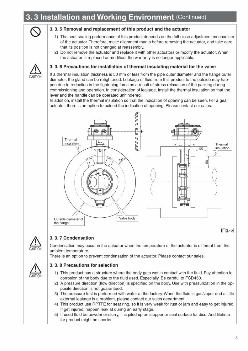
3. 3. 6 Precautions for installation of thermal insulating material for the valve
If a thermal insulation thickness is 50 mm or less from the pipe outer diameter and the flange outer diameter, the gland can be retightened. Leakage of fluid from this product to the outside may hap-pen due to reduction in the tightening force as a result of stress relaxation of the packing during commissioning and operation. In consideration of leakage, install the thermal insulation so that the lever and the handle can be operated unhindered.In addition, install the thermal insulation so that the indication of opening can be seen. For a gear actuator, there is an option to extend the indication of opening. Please contact our sales.
CAUTION
3. 3. 7 Condensation
Condensation may occur in the actuator when the temperature of the actuator is different from the ambient temperature.There is an option to prevent condensation of the actuator. Please contact our sales.
CAUTION
3. 3. 8 Precautions for selection
1) This product has a structure where the body gets wet in contact with the fluid. Pay attention to corrosion of the body due to the fluid used. Especially, Be careful to FCD450.
2) A pressure direction (flow direction) is specified on the body. Use with pressurization in the op-posite direction is not guaranteed.
3) The pressure test is performed with water at the factory. When the fluid is gas/vapor and a little external leakage is a problem, please contact our sales department.
4) This product use RPTFE for seat ring, so it is very weak for rust or jam and easy to get injured. If get injured, happen leak at during an early stage.
5) If used fluid be powder or slurry, it is piled up on stopper or seal surface for disc. And lifetime for product might be shorter.
50
5050
Thermalinsulation
Outside diameter of the flange
Thermalinsulation
Valve body
[Fig.-5]

9
3. 4 Installation Precautions3. 4. 1 Precautions before installation
1) The working pressure, fluid and temperature ranges of this prod-uct depend on the materials of the Seatring and the disc. Prior to installation to the piping, be sure to check the valve specifications with nameplates, catalog, drawings, etc. (Materials are described at the arrow position in [Fig.-6].)
2) Secure scaffolding and illumination required for operation and work at the installation location.
3) Provide supports to pipes as required so that excessive load is not applied to the pipes due to weight or operation of this product.
4) Use standard flat-face or raised-face flanges specified in the product specifications (section 1. 2).5) This product cannot be connected to a lining pipe. Connect the product to a carbon steel pipe
for piping, carbon steel pipe for pressure piping, or stainless steel pipe for piping whose inner diameter is equal to or bigger than the “minimum pipe inner diameter” shown in the table in section 6. 1.
3. 4. 2 Precautions at time of installation
When connecting this product to the piping, pay attention to the following points.If dents or scratches are made on impact, to ensure safety stop use of the product and replace it.
1) Prior to installation to the piping, sufficiently clean piping members to remove shavings, cutting oil, waste material, etc. from the inside.
2) This product and pipes should not be subjected to extreme force, being hit, or impacted. If the product is deformed or damaged due to rough handling, leakage or faulty operation may occur.
3) A pressure direction (flow direction) is specified for this product. When installing, make the pressure direction match the direction indicated by the arrow on the valve body. Pay attention to the following installation conditions. ① Piping with the actuator facing downward is not allowed.② If your application involves pressure being applied in both directions, please contact our sales.③ Be careful of the shaft direction when piping conditions are as shown in [Fig.-7].
Specification name plate
[Fig.-6]
[Fig.-7]
〈Incorrect Installation〉 〈Correct Installation〉 〈Incorrect Installation〉 〈Correct Installation〉
〈Incorrect Installation〉 〈Correct Installation〉
Centrifugal Pump(Horizontal Shaft) Pump Shaft
(Horizontal)
Pump Shaft (Vertical)
Pump Shaft (Vertical)
Pump Shaft (Vertical)
Pump Shaft (Vertical)
Valve Shaft (Horizontal) Valve Shaft (Vertical)
Valve Shaft Valve Shaft
Valve Shaft (Vertical)
Valve Shaft (Vertical)
Valve Shaft (Horizontal)
Valve Shaft (Horizontal)
Axial Pump (Vertical Shaft)
Pump Discharge Pump Discharge
Pump DischargePump Discharge
Flow
Flow Flow Flow
Valve Shaft
Flow Flow
Valve Shaft
Valve ShaftValve Shaft
Valve Shaft
Flow
Flow Flow
Flow
Flow
FlowFlow
Flow
5D or longer
Valve Shaft5D or longer
Valve Shaft5D or longer
5D or longer
All the Valve Shaftshave the same orientation.
The orientation of theValve Shafts is alternating.
Centrifugal Pump (Horizontal Shaft)

10
3. 4 Installation Precautions (Continued)
4) When installing, do not stand on this product or insert the product by hitting it.5) Be sure to use gaskets between the pipe flanges and valve. Joint sheet gaskets*1, spiral gas-
kets*2, and PTFE Envelope gaskets can be used. Do not use soft gaskets such as ones made of rubber. Otherwise, external leakage occurs. For piping gasket sizes, refer to the table in sec-tion 6. 3.
*1 When the joint sheet gaskets are used, select products whose size is in compliance with former JIS B 2404-1999 for 65 mm. For the sizes other than 65 mm, JIS standard products can be used.
*2 For the spiral gaskets, use our special products.6) For this product, fluid is sealed by the Seatring compressed with the force as a result of the
pipe flange compressing the gasket. When connecting the product to the piping, align the center of the product with the center of the flange to press the Seatring accurately. The align-ment for piping work becomes easy by using the alignment rib of this product. If this product is operated while the centers are not aligned, breakage, faulty operation, external leakage, or seat leakage may occur.
7) When tightening piping bolts, pay attention to the following precaution. For tightening proce-dures, refer to section 4. 1. 1.
CAUTION
8) Never weld when this product is in the piping. Installation of the product immediately after welding the pipe flange will lead to heat damage to the Seatring, resulting in adverse consequences. Make sure that the temperature is low and weld spatters have been removed before installing the valve.
9) Damage of the Seatring or flange leakage may occur if the flange face that contacts the seat ring of this product is as shown in [Fig.-9].
Please be careful when using a high-torque impact wrench for piping installation or retighten-ing piping bolts of butterfly valves. Unless an appropriate impact wrench is used and work with it is performed properly, deformation or damage of the valve body, Seatring, pipe flanges, pip-ing bolts, etc. may happen. If you use an impact wrench, use one whose maximum torque is no more than the “Max. allowable value” in the following table.
<Table-3> Maximum Allowable Torque for Metal Flanges (Unit: Nm)
Bolt Nominal Size M12 M16 M20 M22 M24 M30 M36
Max. allowable value64
or less150
or less300
or less400
or less640
or less1280
or less2200
or less
Note) Lubricant should be applied to bolts properly
Using an impact wrench
[Fig.-8]
● Excessive weld penetra-tion, chamfering
The resulting oversized inner pipe diameter may cause flange leakage.
● Sharp edge Sharp angles and burrs may
damage the flange surface.
● Rough surface finishing Protrusions or indentations
on the sealing surface may cause flange leakage. flange leakage.
[Fig.-9]

11
3. 4 Installation Precautions (Continued)
10) Align the primary side pipe with the secondary side pipe properly and make sure that the pipes are parallel and there is no distortion. If the alignment is not proper, external leakage, seat leakage, or faulty operation may occur.
11) When installing a non-return valve, pump, or flexible joint with this product, insert a short pipe between the part and the product. Not inserting a short pipe may cause the disc to make con-tact with the other device during operation, resulting in faulty operation, external leakage, and seat leakage. Refer to section 6. 1 for protruding dimensions of the disc.
12) Connect this product to the primary side of a bent pipe (elbow, tee). If the product is connected to the secondary side by necessity, secure a straight pipe distance of 5 times or more of the pipe diameter from the bent pipe. In addition, the product should be positioned so that the flow velocities at the right and left sides of the shaft are the same. [Fig.-7]
If the product is closely connected to the secondary side of a bent pipe, etc., flow velocity and pressure distribution cause unbalanced torque on the disc, which may increase the operating force or have an adverse effect on the performance and service life of the product.
13) When this product is connected to the secondary side of a control valve, pump outlet, or re-ducer, secure a straight pipe distance of 5 times or more of the pipe diameter. In addition, the valve should be positioned so that the flow velocities at the right and left sides of the shaft are the same. [Fig.-7]
14) When replacing a valve with a long face-to-face dimension (e.g. gate valve, globe valve, ball valve) with this product, you must insert a short pipe and adjust the total length of the short pipe and the face-to-face dimension of this product to the face-to-face dimension of the origi-nal valve flange. Use the equation below when making a short pipe. [Fig.-11]
15) After piping work is completed, set this product to the full-open positon and check that the disc does not make contact with the inner surface of the flange.
16) Also, insulate around the valve body when the valve will be used with high-temperature fluids that exceed 60°C.
Poor centering alignment of the pipes
Poor parallel alignment
Distortion
[Fig.-10]
<Table-4>
Length of short pipeL2 = L1 – L - t mm
L2 : Length of short pipe mm
L1 : Face-to-face dimension of existing valve
mm
L : Face-to-face dimension of TOMOE butterfly valve
mm
t : Thickness of gasket packing mm
[Fig.-11]
LL2
L1
Butterfly valve
Short pipe Pipe
Piping gasket
Existing valve
L1t t
tt
t
Piping gasket
Pipe

12
Check forany leak
[Fig.-12]
3. 5 Precautions for Safe Handling After Installation
CAUTION
3. 5. 1 Precautions for safe handling after installation
After this product is connected to the piping, perform checks while paying attention to the following points. If the checks are not performed, serious accidents may occur, such as damage of the product.
1) Prior to operating, clean pipes and remove foreign material from the inside and outside of the pipes.
2) Prior to operating, increase the internal pressure of the piping and check for leakage from the flanges, glands, and bottom. Make sure that the internal pressure does not exceed the rated pressure of the valve at the leakage check.
3) If leakage from the flanges is observed, reduce the pressure and then retighten the piping bolts and nuts.
Refer to “Piping bolt tightening procedures” in section 4. 1. 1 10) for the tightening proce-dures. If leakage from the bottom is observed, check for looseness of the hexagon bolts at the bottom. If leakage from the glands is observed, retighten the hexagon bolts of the glands. If leakage does not stop, release the piping internal pressure and remove this product from the piping. Then replace the glands or spare parts at the bottom.
4) When performing a pressure test of the piping including this product, the pressure should be the rated pressure of this product × 1.5 times or less.
When performing a pressure test of the piping where the pressure exceeds the rated pressure, set the product to the full-open positon.
5) After installation, open and close the product about once every two weeks if the product is not used for long periods of time.
6) Do not use this product as a blank flange by setting the product to the full-close position.
WARNING
WARNING
CAUTION
CAUTION
3. 5. 2 Precautions for operating this product
1) Never loosen the bolts, pins or piping bolts of this product when the inside of the piping is un-der pressure. Otherwise fluid jets to the outside, which is dangerous.
2) Do not remove the actuator from this product when the inside of the piping is under pressure. Unexpected abrupt valve operation may occur or the shaft may spring out.
3) When this product is used at the intermediate opening, the opening should be 30° or more. If the product is used continuously with the opening of 30° or less, damage of sheets, or dam-age, vibration and noise of the piping may occur due to jet speed increase or cavitation. (Refer to section 3. 1. 4.)
4) Do not loosen the stopper bolts of the actuator and the indicator installation bolts of the lever. Otherwise, seat leakage may occur because the full-close position is shifted. When the stopper bolts are moved, perform full-close position adjustment again in accordance with “Valve Body Full-Close Position Adjustment Proce-dure” in section 5. 5.
5) For a manual gear type actuator, the stopper works when the indicator shows full-open or full-close. Do not apply excessive force to the handle wheel from this state. Otherwise, the gear box will be damaged.
This product has been adjusted so that the maximum sealing performance can be obtained at the full-close position adjusted with the stopper bolts. The sealing performance will be dete-riorated and torque becomes low at a position which is deeper or shallower than the adjusted position. Therefore, it is not necessary to rotate the handle forcibly.
6) Opening and closing operation of the lever and the handle wheel must be done by hand. When operating the handle using an ancillary tool, such as a Wilky key, this may cause damage or failure of the product.
7) After installation and before operation, be sure to open and close the product once or twice.8) After trial operation or operation over a fixed period, retighten the piping bolts and nuts. Par-
ticularly, in applications involving high-temperature fluids, the tightening force of the bolts may be reduced due to stress relaxation of the piping gaskets, which may cause flange leakage.
[Fig.-13]
Indicator
Stopper bolt
Hexagon nut

13
3. 6 Maintenance3. 6. 1 Daily InspectionPerform daily inspection on the following.
<Table-5> Daily Inspection ProcedureInspection Description Inspection Points Inspection
Procedure Countermeasure
Fluid external leakage
Pipe joints Visual checkRetighten the piping bolts and nuts.Align the valve center with the pipe center and retighten the piping bolts.
Bottom, valve surface Visual checkDisassembly and maintenance (Spare parts replacement*1)Valve replacement
Gland area Visual check Retighten the bolts.
Abnormal noise, vibration
Appearance of the valve and actuatorPiping around the valveBolts and nuts
Listening, Check by touch
Change the valve opening. Review the flow rate and pressure.Retighten the bolts and nuts. Remove the sources of vibrations.Disassembly and maintenance (Check for damage of the parts.)
Looseness of the bolts and nuts Bolts and nuts Visual check,
Check by touch
Retighten the bolts and nuts.Retighten the pressure part after reducing pressure.
Seat leakage
Presence or absence of leakage from the second-ary side (Flow meter, pressure gauge, drain)
Listening,Visual check,Measurement
Check that the opening and closing positions are correct with the indicator. Remove foreign material by flushing water with the valve fully open (section 3. 6. 6).Remove the valve from the piping (section 3. 6. 7) and perform check and cleaning.Replace *1 pare parts
Valve operation check
Check of opening and closing positionsManual valve: OperabilityAutomatic valve: Operation
Visual check,Operational feeling
Check that the opening and closing positions are correct with the indicator.
Valve damage check Valve surface Visual check If any damage is observed, stop use of the
valve and replace it.*1 Replace the spare parts around after 3000 times of opening and closing (Open - Close - Open: 1 time) or
one year operation at room temperature using fresh water. The replacement timing may become faster de-pending on the working environment. Please replace the spare parts (refer to the Expanded View in section 2.1) based on the number and term.
3. 6. 2 Periodic inspectionPerform periodic inspection on the following items once every 6 months.
<Table-6> Periodic Inspection ProcedureInspection Description Inspection Points Inspection Procedure Countermeasure
Corrosion and damage of the disc
DiscRemove the valve from the piping and perform visual check.
Valve replacement
Abrasion and damage of the Seatring
SeatringRemove the Seatring from the piping and perform visual check.
Clean the disc and Seatring (section 3. 6. 3).Replace *1 pare parts Valve replacement.
Valve operating condition Valve, actuator Opening/Closing
operation Actuator replacement, valve replacement
*1 Replace the spare parts around after 3000 times of opening and closing (Open - Close - Open: 1 time) or one year operation at room temperature using fresh water. The replacement timing may become faster de-pending on the working environment. Please replace the spare parts (refer to the Expanded View in section 2. 1) based on the number and term.
3. 6. 3 Cleaning of the disc and disc stopperFor pneumatic cylinders and motors, before putting your hand in the valve, take precautions, such as shut-ting off air sources and turning off the power, to prevent the actuation. It is very dangerous if your hand is caught by the suddenly closing the disc. Particularly, for single-acting cylinder, it is necessary not only to shut off power supplies but also to check that the operation pneumatic pressure has been released.
1) When removing this product from the piping and cleaning it for periodic inspection, etc., clean the Seatring using a clean waste cloth/sponge, etc. and a neutral detergent or alcohol, while avoiding scratches on the Seatring.
2) Clean the edge of the disc with a waste cloth.3) Check for scratches and wear on the Seatring inner surface and the edge of the disc.4) Check that no foreign material adheres to the disc stopper.

14
3. 6 Maintenance (Continued)
3. 6. 4 Replacement of spare parts
This product should be disassembled and assembled in a clean location which is free from dirt, waste material and dust.Refer to section 2. 1 “Expanded View and Part List” and “MAINTENANCE” in Chapter 5 for type and replacement procedures of spare parts.
3. 6. 5 Rust prevention procedure
Be sure to use the rust preventive agent specified blow.
<Table-7> Rust Prevention Procedure
To be applied to: Rust preventive agent Product Name (Manufacturer)
Plated partsIndicator, bolts, nuts and handle shaft
Rust preventive agentFerro-Guard #1009(US Ronco Laboratories, INC.)
WARNING
3. 6. 6 Countermeasures to address abnormalities
1) The work should be performed while wearing protective gear, such as a helmet, safety belt, protective glasses, working gloves and safety shoes, in accordance with laws and regulations, and safety provisions of business establishments.
2) When the fluid which flows through the piping is toxic, flammable or corrosive, adequate safety measures should be taken.
3) Before retightening the pipe flanges, be sure to reduce the pressure in the piping to the atmo-spheric pressure.
4) In case of abnormal operation, possible causes are clogging of foreign material, damage of the Seatring, etc. If you continue to use the valve, serious accidents may occur due to dam-age. Perform checks in accordance with the following procedures.① To remove foreign material, keep the disc in the full-open positon and flush fluid to remove
foreign material.② If normal operation is still not restored through the above procedure, damage of the seat
ring is possible. Remove the Seatring from the piping and check the Seatring.
WARNING
3. 6. 7 Removal/Installation from/to the piping
1) Before removing this product from the piping, release the residual pressure and remove fluid from the equipment and the piping completely. Otherwise, jetting of fluid to the outside and unexpected movements may occur.
2) Take necessary measures so that fluid does not flow into applicable pipes accidentally during the work.
3) When this product is removed, fluid may leak from the inside. Provide protection as required.4) Remove/install this product from/to the piping with the product in the full-close position so that
the disc does not protrude from the face. (Refer to section 4. 1. 1 for detailed procedures.)5) Remove all the bolts and nuts except those on the lower side. Remove the valve. At this time,
use of jack bolts in between the flanges will assist in removing the valve more easily.
3. 6. 8 Disposal
1) Do not dispose of this product by incineration. There is a possibility of generation of toxic gas from synthetic rubber or nylon resin parts and bursting. Therefore please dispose of this prod-uct as general industrial waste. The product does not contain materials which cannot be dis-posed of as general industrial waste.
2) For segregated disposal, classify the parts in accordance with materials specified on drawings.3) This product should be disposed of in accordance with laws and regulations, local government
ordinances, standards of business establishments, etc.

15
4 INSTALLATION4. 1 Installation Procedure
4. 1. 1 Installation procedure
At installation, read “Installation Precautions” in sec-tion 3. 4 thoroughly and then perform installation in accordance with the following procedures.
When installing a non-return valve, pump, or flexible joint made of rubber with this product, insert a short pipe between the part and this product. Otherwise, the disc may make contact with the other device during operation, resulting in faulty operation and leakage.
CAUTION
1) Clean the flange face that will make contact with this product. If there is rust or some other foreign material sticking to the flange face, remove it and clean the flange face with a suitable cleaning fluid (alcohol, neutral detergent, etc.). [Fig.-14]
Remove foreign material from the piping completely before connecting this product to the piping.
2) Before installation or removal work, set the valve disc in the full-close position. [Fig.-15]
3) After aligning both flanges, insert the piping bolts as shown in the figure and secure the product to prevent it from dropping. [Fig.-16]
4) Insert jack bolts in the position shown in the figure to widen the distance between the flanges. Push the flanges and make the distance between the flanges 6 to 10 mm longer than the valve face-to-face dimension. Do not remove the jack bolts until all the piping bolts are installed. [Fig.-17][Fig.-18]
5) Do not suspend this product by hanging a hook, etc. on the handle. Suspend the product by tying down a well-balanced position, such as the neck section of the product, with material that does not damage the body, such as a nylon sling.[Fig.-18]
6) A pressure direction (flow direction) is specified for this product. When installing, make the pressure direction of the valve match the direction indicated by the arrow on the valve body. Insert the product while taking care not to damage the valve flange face. At installation, if the product is pushed in the flange forcibly, the flange face will be damaged, which will cause leakage.
Be sure to widen the distance between the flanges using jack bolts, etc. before inserting the product. [Fig.-18]
7) Insert piping gaskets between the end faces of the valve and the pipe flange faces.
[Fig.-17]
[Fig.-15]
Close
Jack bolt
Face-to-face dimension+ 6 ~ 10mm
[Fig.-18]
Piping gasket
Piping gasket
Jack bolt
Neck
Flow direction indicator
[Fig.-14]
[Fig.-16]

16
4. 1 Installation Procedure (Continued)
8) When this product is inserted completely, insert the piping bolts to support the alignment rib.
9) After all the piping bolts are installed, remove the jack bolts.
10) Align the flanges with the product accurately. Tight-en the piping bolts with the following procedures so as not to tighten the bolts on one side too much or too little. For this product, fluid is sealed by the seat ring compressed with the force as a result of the pipe flange compressing the gasket. When con-necting the product to the piping, align the center of this product with the center of the flange to press the Seatring accurately. The alignment for piping work becomes easy by using the alignment rib. If this product is operated while the centers are not aligned, breakage, faulty operation, external leak-age or seat leakage may occur.※ When you use an impact wrench, be sure to
read “section 3. 4. 2”.
11) For accurate alignment between the flanges and this product, tighten the flanges at both ends tem-porarily and tighten this product finally first. [Fig.-21]
12) After installation, open and close the product to verify that the operations from/to full-open to/from full-close are smooth.
[Fig.-21]
Piping bolt tightening proceduresWhen there is no appropriate tightening procedure in business establishments or internal standards, tighten the bolts and nuts with the following procedures.
1) Clean the bolts and nuts and apply lubricant to them. (Do not use rusty or damaged bolts and nuts.)2) Tighten the bolts and nuts by hand in any desired order.3) Tighten the bolts and nuts in any desired order with approx. 20% of the speci-
fied tightening torque.4) Tighten the bolts and nuts, alternate diagonally (refer to the right figure) with
approx. 70% of the specified tightening torque.5) Tighten the bolts and nuts, alternate diagonally, with approx. 100% of the
specified tightening torque.6) Tighten the bolts and nuts, alternate diagonally, with approx. 100% of the
specified tightening torque again.7) Tighten the bolts and nuts clockwise with approx. 100% of the specified tight-
ening torque.
For this product, bolts that are tightened once may become loose due to stress relaxation of the piping gaskets.Be sure to perform retightening in 6) and 7) repeatedly until the bolts and nuts are tightened evenly.
[Fig.-20]
①
⑤
③
⑦
⑧
②
④
⑥
Example) Bolt tightening sequence
CAUTION
[Fig.-19]
Alignment ribs
Jack bolt
Flange of both ends
Flange of both ends

17
5 MAINTENANCE5. 1. Seatring Disassembly/Assembly Procedures
5. 1. 1 Seatring disassembly procedure
For periodic inspection or in case of trouble due to damage and wear of the Seatring, etc., carry out the following procedures while referring to the expanded view.
1) Secure the metal section of the body ① using a vice so that the flanges are not damaged. Open the disc ② approx. 30°. [Fig.-22]
2) Remove the Hex. socket set screws � on the front of the Seatring retainer ⑦ . [Fig.-22]
3) Carefully grasp the inner side of the Seatring re-tainer ⑦ and pull it out toward you by hand. The ball ⑳ inserted on the outer side of the retainer may pop out during removal, so care must be taken not to lose it. [Fig.-22]
4) Remove the Seatring ⑤ from the seat ring retainer ⑦ . [Fig.-22]
5) Thoroughly clean the Seatring mounting faces of the body ① and the Seatring retainer ⑦ , and the disc ② using a suitable cleaning fluid, such as alcohol or a neutral detergent. [Fig.-23]
5. 1. 2 Seatring assembly procedure
1) Set the disc ② to the full-close position. [Fig.-24]
2) Install a new Seatring ⑤ to the Seatring retainer ⑦ . Set the ball ⑳ on the periphery of the Seatring retainer ⑦ and install it on the body ① . [Fig.-24]
3) Screw the set screws � into the tap hole provided on the front face of the Seatring retainer ⑦ . Make sure that the Hex. socket set screws � is com-pletely screwed in so that it does not protrude from the front face of the Seatring retainer ⑦ . [Fig.-25]
[Fig.-25]
4) Open and close the valve to ensure that the seat ring retainer ⑦ is properly secured to the body.
[Fig.-22]
[Fig.-23]
[Fig.-24]⑦ Seatring retainer
� Hex. socket set screw
⑳ Ball
⑤ Seatring
② Disc
� Hex. socket set screw
⑳ Ball
⑤ Seatring
⑦ Seatring retainer
② Disc① Body
� Hex. socket set screw
⑳ Ball

18
5. 2 Removal of Valve Body and Actuator
5. 2. 1 Lever type
1) Secure the metal section of the body ① using a vice so that the flanges are not damaged. Set the valve opening to the full-open position. [Fig.-26]
2) Make alignment marks on the body ① and indica-tor L21 .
3) Remove the Hex. socket set screw L26 and hexagon nut L27 that secure the shaft ③ and lever.
4) Remove the hexagon nuts and spring washers (2 pairs) that secure the body ① and indicator L21 .
5) Lift the lever upward and remove it.
6) Be careful not to lose the removed parts.
5. 2. 2 Worm gear
1) Secure the metal section of the body ① using a vice so that the flanges are not damaged. Set the valve opening to the full-open position. [Fig.-27]
2) Make alignment marks on the connecting part be-tween this product and the actuator.
3) Remove the hexagon bolts and spring washers (4 pairs) that secure the body ① and actuator.
4) Lift the actuator upward and remove it.
5) Be careful not to lose the removed parts.
[Fig.-26]
[Fig.-27]
Before installing/removing the actuator while this product is installed to the piping, check that the pressure in the piping is atmospheric pressure and the fluid is drained out from the inside.
WARNING
Actuator
Screws③ Shaft
� Bonnet
� Heat insulation sheet
① Body
② Disc
Lever
Screws
L26 Hex. socket set screw
L21 Notch plate
③Shaft
L27 Hexagon nut
� Bonnet
① Body

19
5. 3 Disassembly/Assembly Procedures of Gland area5. 3. 1 Disassembly procedure of Gland area
1) Set the disc ② to the full-close position.
2) Remove the hexagon bolts ⑰ and then remove the gland flange ⑯ .
3) Pull out the rough gland ⑮ from the body ① .
4) Remove the gland packing ⑭ from the body ① us-ing a packing tool or a scriber or similar tool. If the packing retainer ⑬ can be removed, remove it as well.
5. 3. 2 Assembly procedure of Gland area
1) Clean the gland packing hole on the body ① to remove waste material and other foreign material.
2) Clean the parts before assembly.
3) When the packing retainer ⑬ was removed, install it in the gland packing hole of the body ① .
4) Insert the gland packing ⑭ into the gland packing hole on the body ① and attach the rough gland ⑮ onto it. When inserting the gland packing ⑭ , insert the male adaptor (c), V rings (3 pcs)(b), and the female adaptor (a) in that order, one by one, in the direction shown in [Fig.-29].
5) Attach the gland flange ⑯ and tighten the hexagon bolts ⑰ equally on the left and right.
6) Set the disc ② to the full-close position.
7) After installing the actuator, open and close the valve to verify that the operations are smooth.
[Fig.-29]
[Fig.-28]
⑮ Rough gland
⑬ Packing retainer
⑭ Gland packing
⑯ Gland flange
① Body
⑭ Gland packing
abc
a
b
c

20
5. 4 Assembly Procedure of Valve Body and Actuator
5. 4. 1 Lever type
1) Secure the metal section of the body ① using a vice so that the flanges are not damaged. Set the valve opening to the full-open position. [Fig.-30]
2) Secure the indicator L21 and bonnet � to the body ① with the hexagon bolts, hexagon nuts and spring washers (2 pairs).
3) Install the lever to the shaft ③ while aligning the lever with the full-open position of the indicator L21 and secure the lever with the Hex. socket set screw L26 and hexagon nut L27 .
4) After assembly, turn the lever to verify that the opening and closing operations are smooth.
5) Finally, adjust the full-close position in accordance with “Full-close position adjustment procedure (1T lever)” in section 5. 5. 2.
5. 4. 2 Worm gear type
1) Secure the metal section of the body ① using a vice so that the flanges are not damaged. Set the valve opening to the full-open position. [Fig.-31]
2) Set the actuator to the full-open position.
3) Insert the thermal insulating sheet � and bon-net � onto the body as shown in the figure, and then insert the actuator. At this time, check that the alignment marks of the body ① and actuator are aligned.
4) Secure the body ① and actuator by tightening the hexagon bolts and spring washers (4 pairs).
5) Finally adjust the full-close position in accordance with “Full-close position adjustment procedure (2U gear)” in section 5. 5. 3.
[Fig.-30]
・ When installing the original actuator to this prod-uct without the actuator, check the alignment marks and serial No. before assembly to ensure that the actuator is the identical one which was removed from the product.
・ Improper assembly causes misalignment of the closing position, which may lead to leakage.
CAUTION
[Fig.-31]
Actuator
Screws③ Shaft
� Bonnet
� Heat insulation sheet
① Body
② Disc
Lever
Screws
③ Shaft
� Bonnet
① Body
L26 Hex. socket set screw
L21 Notch plate
L27 Hexagon nut

21
5. 5 Valve Body Full-Close Position Adjustment Procedure5. 5. 1 Full-close position reference
< Table-8 > Full-close Position Reference
Nominal Size Full-close Position Reference(* For lever type and worm gear type only)mm inch
40 1 1/2- 0.5 ± 0.550 2
65 2 1/280 3
- 1.0 ± 1.0100 4125 5150 6200 8250 10 - 1.5 ± 1.5300 12
Dimensions are specified for the assembled product.Measure the dimensions at two points of A and B. The full-close position reference = B – A.
1) Set this product to the full-close positon.
2) Loosen the hexagon nut (C). Move the lever while it is hooked in the notch to adjust the full-close posi-tion so that the position meets the full-close posi-tion reference.
3) Tighten the hexagon nut (C) using a spanner at the adjusted position.
4) Turn the lever to verify that the opening and closing operations are smooth.
5) If re-adjustment is required, repeat the procedures from the above 1).
※ The full-close and full-open positions are ad-justed when shipped.
※ If the full-close position is outside the specifica-tions, the body may be broken when the product is opened and closed.
[Fig.-32]
[Fig.-33]
[Fig.-34]
5. 5. 3 Full-close position adjustment procedure (2U gear)
5. 5. 2 Full-close position adjustment procedure (1T lever)
1) Set this product to the full-open positon. Check that the indicator of the gear box is “OPEN”.
2) Loosen the right hexagon nut (A) in [Fig.-34].
3) Turn the hexagon stop screw (B) by the required angle using a hexagonal bar wrench so that the full-close position meets the full-close position reference. When the hexagon stop screw (B) is turned clockwise, the full-close position of the valve becomes shallow.
4) After the adjustment, secure the hexagon stop screw (B) using a hexagonal bar wrench and tight-en the hexagon nut (A) using a spanner.
5) Operate the gear and check that the product can be opened and closed.
6) If re-adjustment is required, repeat the procedures from the above 1).※ The full-closed and full-open positions are ad-
justed when shipped.※ If the full-close position is outside the specifica-
tions, the body may be broken when the product is opened and closed.
A B
X-X
10~20°
X
X
Depth gauge or the like
OpenRotation direction
Disc
Close
Indicator
Hex. socket set screw(B)
Hexagon nut(A)
Notch plate
Hexagon nut (C)

22
6. Piping Data6. 1 Minimum Inner Pipe Diameter and Disc Protruding Dimension at Full-open Position
< Table-9 > Minimum Inner Pipe Diameter and Disc Protruding Dimension at Full-open Position
Unit: mm
Nominal SizeMinimum Inner Pipe Diameter
Disc Protruding Dimension at Full-open
Position
mm inch A B C
40 1 1/2 36 5.4 0.9
50 2 42 0.0 5.9
65 2 1/2 59 5.1 12.1
80 3 73 15.0 16.0
100 4 92 21.0 23.2
125 5 117 31.5 32.9
150 6 143 45.8 43.4
200 8 193 67.6 63.6
250 10 240 88.2 80.9
300 12 291 107.2 104.4
Note ) The disc of the butterfly valve is inserted into a pipe at full-open position. When you use a pipe or flange whose diameter is less than the minimum inner pipe diameter, insert a spacer, etc. between the product and flange.
For details, please contact our sales department.
6. 2 Applicable Pipes<Table-10> Applicable Pipes
Nominal Size JIS G3452 JIS G3454 JIS G3459
mm inch SGP Sch20 Sch40 Sch10S Sch20S
40 1 1/2 ○ - ○ ○ ○50 2 ○ ○ ○ ○ ○65 2 1/2 ○ ○ ○ ○ ○80 3 ○ ○ ○ ○ ○
100 4 ○ ○ ○ ○ ○125 5 ○ ○ ○ ○ ○150 6 ○ ○ ○ ○ ○200 8 ○ ○ ○ ○ ○250 10 ○ ○ ○ ○ ○300 12 ○ ○ ○ ○ ○
[Fig.-36]
A
B C

23
6. 3 Piping Gasket Dimensions6. 3. 1 Joint sheet gaskets<Table-11> Joint Sheet Gasket Dimensions
Unit: mm
Nominal Size JIS FLANGEANSI FLANGEANSI 125,150Lb
mm inch D1D2
D1 D2JIS 5K JIS 10K
40 1 1/2 49 83 89 48.5 85.9
50 2 61 93 104 60.5 104.6
65 2 1/2 77 118 124 73.2 124.0
80 3 90 129 134 88.9 136.7
100 4 115 149 159 114.3 174.8
125 5 141 184 190 141.2 196.8
150 6 167 214 220 168.1 222.2
200 8 218 260 270 218.9 279.4
250 10 270 325 333 273.0 339.9
300 12 321 370 378 323.8 409.4
Note) øD1 dimension of 65 mm is the old JIS dimension.
[Fig.-37]
6. 3. 2 Spiral gaskets<Table-12> Spiral Gasket Dimensions
Unit: mm Nominal Size JIS 10K ANSI 150Lb
mm inch D1 D2 D3 D4 D1 D2 D3 D4
40 1 1/2 48 54 73 89 48 54 73 85
50 2 61 69 88 104 61 69 88 104
65 2 1/2 73 81 100 124 73 81 100 123
80 3 89 97 120 134 89 97 120 136
100 4 115 124 146 159 115 124 146 174
125 5 140 151 177 190 140 151 177 196
150 6 166 178 207 220 166 178 207 222
200 8 217 227 257 270 217 229 257 279
250 10 268 282 318 332 268 285 318 333
300 12 319 331 362 377 319 335 362 409
Note) If minor gas leakage (100 ppm or less) is a problem, please contact our sales department.
[Fig.-38]
6. 3. 3 Punching gasket and PTFE envelope gasket<Table-13> Available punching gasket and PTFE envelope gasket
Nominal SizeInner diameter
permissible max. dimension
Joint Sheet andPTFE punching Gasket (t ≦ 2 mm)
PTFE envelope Gasket (NIPPON VALQUA INDUSTRIES, LTD.,
Flow-less Gasket (7030,7031,7035 series))
mm inch D JIS 5K JIS10K ANSI 150Lb JIS 5K JIS10K ANSI 150Lb
40 1 1/2 55 ○ ○ ○ ○ ○ ○50 2 69 ○ ○ ○ ○ ○ ○65 2 1/2 77 ×*1 ×*1 ○ ×*1 ×*1 ○80 3 97 ○ ○ ○ ○ ○ ○
100 4 124 ○ ○ ○ ○ ○ ○125 5 151 ○ ○ ○ ○ ○ ○150 6 178 ○ ○ ○ ○ ○ ○200 8 227 ○ ○ ○ ○ ○ ○250 10 282 ○ ○ ○ ○ ○ ○300 12 331 ○ ○ ○ ○ ○ ○
Remarks *1 : These gasket cannot use for 65mm of JIS piping. If use for 65mm, you must choose under 77mm for the inner diameter. PTFE envelope gasket, NIPPON VALQUA product only available.(In other manufacturers, product size is unavailable.)

24
6. 4 Piping Bolt Sizes
■ Long bolts and nuts [Indication Example] 8 - M16 × 145 × 16
Quantity
Nominal Size M
Bolt length L (mm)
Nut width H (mm)
< Table-14 > Piping Long Bolt and Nut Sizes
Nominal SizeJIS 5K JIS 10K
ASME/ANSICLASS 150mm inch
40 1 1/2 4-M12×100×12 4-M16×120×16 4-1/2-13UNC×115×16
50 2 4-M12×120×12 4-M16×130×16 4-5/8-11UNC×140×16
65 2 1/2 4-M12×120×12 4-M16×145×16 4-5/8-11UNC×155×16
80 3 4-M16×130×16 8-M16×145×16 4-5/8-11UNC×155×20
100 4 8-M16×145×16 8-M16×145×16 8-5/8-11UNC×155×20
125 5 8-M16×145×16 8-M20×170×20 8-3/4-10UNC×175×22
150 6 8-M16×145×16 8-M20×170×20 8-3/4-10UNC×175×22
200 8 8-M20×170×20 12-M20×170×20 8-3/4-10UNC×205×22
250 10 12-M20×190×20 12-M22×190×22 12-7/8-9UNC×215×24
300 12 12-M20×190×20 16-M22×190×22 12-7/8-9UNC×215×24
[Fig.-39]
Long bolt・nut (fully threaded)
H: Nut height
H
L
M

25
7. TROUBLESHOOTING7. 1 Troubleshooting
Problem Main Cause Countermeasure
1. Leakage from between the body and piping flange faces
[Fig.-40]
The piping bolts are loose or they were not tightened evenly.
After reducing the pressure, loosen the piping bolts, and then retighten them by diagonal sequence.(4. 1. 1-10) “Piping bolt tightening procedures”)
The piping flange face is scratched or there is waste ma-terial or other foreign material adhering.
Remove the valve. Repair and clean the piping flange face. After cleaning, install the valve again. (3. 4. 2-1)
The flanges or pipes are mis-aligned.
Remove the valve. Align the flanges/pipes and make the flanges/pipes parallel. (3. 4. 2-6),10))
The valve is misaligned.Loosen the bolts and realign the valve.(3. 4. 2-6),10))
No piping gasket is inserted, or improper gasket is inserted.
Insert a proper gasket between the pipe flange and valve.(3. 4. 2-5))
2. Leakage from the gland bottom
[Fig.-41]
The gland bolts are loose.The gland packing has worn out or has deteriorated.
Retighten the gland bolts.If leakage is not reduced, replace the gland packing.
The bottom bolts are loose.The bottom gasket has deterio-rated.
If the hexagon bolts are loose, retighten them.If leakage is not reduced, replace the bottom gasket.
The body and shaft have de-formed.
When external force caused by a support secured to the valve body, etc. is applied to the valve in operation, deformation of the body is possible. Check visually for deformation of the shaft. If any deformation is observed, valve replacement is required.
The body is damaged.If any cracks or breakage are observed on the body, stop use of the valve immediately and replace the valve.
3. Valve seat leakage
[Fig.-42]
Wrong material was selected for the fluid application and the parts are corroded.
Replace the valve with one made of the proper material.For details, please contact our sales department.
The product specification does not meet the requirement for the fluid.
Use the product within the product specifications (temperature, pressure, flow rate, fluid type).
There is damage to the disc or Seatring due to the presence of foreign material inside the piping.
When the Seatring is damaged, replace the Seatring.If any abnormality is observed on the disc edge, replace the valve.
The full-close position of the disc is changed.(The actuator installation bolts are loose, etc.)
Clean the valve seat and body stopper (3. 6. 3) and adjust the full-close position correctly (5. 5). In addition, check that there is no problem with the actuator output.
There is torsion of the shaft due to increase in the opening/clos-ing torque.
Replace the valve.
Pressure between the Seatring and the disc is not even due to un-even tightening of the piping bolts.
Loosen the piping bolts and realign the valve and the flange. Then retighten the piping bolts. (4. 1. 1-10) “Piping bolt tighten-ing procedures”)
Wearing and deterioration of the Seatring due to long period of use or high frequency of open-ing and closing operations
Replace the Seatring.

26
7. 1 Troubleshooting (Continued)
Problem Main Cause Countermeasure
4. The valve does not work.
Faulty operation
[Fig.-43]
The disc interferes with the pip-ing or other devices.
Insert a short pipe or spacer between the valve and flange to avoid interference. (section 6. 1) In this case, remove and check the disc sealing part because there is a high possibility that it is damaged.
The valve is deformed or dam-aged.
Check the appearance of the body, disc and shaft to ensure that there is no deformation, dent, damage, corrosion, etc. If any of these are observed, replace the valve.
Actuator parts are damaged. For details, refer to the instruction manual of the actuator.
The piping bolts are loose or tightened unevenly.The valve is misaligned.The pipe flanges are mis-aligned, are not parallel, or distorted.
If tightening force of the bolts is uneven or the contact areas are not equal, the valve seat compression is uneven and the torque may increase. Loosen the bolts and retighten them by diagonal sequence. (section 3. 4. 2-6),10), section 4. 1. 1-10) “Piping bolt tightening procedures”)
Increased torque due to pres-ence of foreign material in the piping.
Set the valve to the full-open position and flush the foreign material out to remove it.(section 3.6.6-4)) In this case, remove and check the disc sealing part because there is a high possibility that it is damaged.
Powdered foreign material inside the piping enters the bearings.
If rust powder or powdered foreign material is inside the piping, any foreign material which entered the bearings may interfere with the shaft rotation.If there is a possibility of this remove the valve and clean it.
The product specifications do not conform to the fluid specifi-cations.
For automatic valves, the actuator size is selected in accordance with the working conditions (temperature, pressure, flow rate, fluid type). If the working conditions are changed, the valve may not work due to insufficient actuator torque.Please contact our sales department.
The actuator rated output is not available.(For automatic valves)
For cylinders, check the following items.
1) The rated supply pneumatic pressure and the supply amount are secure.
2) The bypass valve is closed.3) The operation air stop valve is open.4) The speed controller is open properly.5) The exhaust port plug has been removed.
For motors, check the following items.1) The rated power voltage is supplied.2) Voltage is applied to the motor properly.3) The thermal protector, etc. is not activated.4) Two or more actuators are not operated with one switch.5) No water is inside the motor.
For details, refer to the instruction manual of each actuator.
The valve body is deformed because abnormal force is ap-plied.
If a support is installed to the valve neck section or actuator, the sup-port may produce a force that deforms the valve.Remove the support member and check the valve.If this product interferes with other devices or buildings, the force is produced too. Avoid the interference of the product.
Abnormal interference of the disc due to damage or deforma-tion of the Seatring.
Replace the Seatring.If any abnormality is observed on the disc edge, replace the valve.
Parts, such as the disc, shaft, body and joint, are damaged.
If none of the above are applicable, the valve parts may be dam-aged, and replacement of the parts may be required. Please contact our sales department.

27
MEMO

* "Before placing an order" has been described since 25 May, 2005.
■ CONTACT
●Head Office3-11-11 Shinmachi, Nishi-ku, Osaka 550-0013, JapanTelephone: 81-6-6110-2370 Telefax: 81-6-6110-2371 E-mail:[email protected]
Global Sales Operations
www.tomoevalve.com
No. 317, Kamol Sukosol Building, Unit B, 12th Floor, Silom Road, Silom Sub-district, Bangrak District, Bangkok 10500, ThailandTelephone: +66-(0)-2117-0429 Telefax: +66-(0)-2117-0148 E-mail: [email protected]
TOMOE VALVE (THAILAND) CO., LTD.
15700 International Plaza Drive Suite150, Houston TX, 77032 USATelephone: +1-281-358-7571 Telefax: +1-281-358-7861
TOMOE USA Inc.
Room 1102, Building A, St.NOAH Plaza, No.1759 Jinshajiang Road, Putuo district, Shanghai. 200333, ChinaTelephone: +86-21-52715628 Telefax: +86-21-52653691 E-mail: [email protected]
TOMOE VALVE INDUSTRY (NANTONG) CO., LTD. http://www.tomoe.sh.cn
BlockF2 Latrade Industrial Park, JI. Sei Binti Tanjung Uncang, Batam 29422 IndonesiaTelephone: +62-778-395-466 Telefax: +62-778-396-475 E-mail: [email protected]
PT. TOMOE VALVE BATAM http://www.tomoe-batam.com
No 2, Toh Guan Road East, #02-02, Singapore 608837Telephone: +65-68995060 Telefax: +65-68995061 E-mail: [email protected]
TOMOE VALVE ASIA PACIFIC PTE. LTD. www.tomoe.com.sg
Clearwater Road, Queensway Meadows Industrial Estate,Newport, South Wales NP19 4ST, United KingdomTelephone: 44-1633-636800 Telefax: 44-1633-636801 E-mail:[email protected]
www.tomoeeurope.co.ukTOMOE VALVE LIMITED
Cat.No.EG1402-③ 2018.10.31-Ph
WARRANTY PERIODThe warranty period of the delivered product should be eighteen (18) months after shipment from our factory or one (1) year after the date of starting trial operation, whichever comes first.
SCOPE OF WARRANTY AND INDEMNITYIf any damage or problem should occur during the foregoing warranty period due to our fault, TOMOE VALVE will replace or repair any defective part of the product free of charge at the place where the product was purchased or where it was delivered (limited to Japan). However, warranty is not applicable if the causes of defects should result from the following:
1) The failure was caused by inappropriate conditions, environment, handling or use methods, etc. which are not specified in the catalog, specifications or other relevant documents that had been made and entered into be-tween the customer and TOMOE VALVE.
2) The failure was caused by a product other than the delivered TOMOE's product. 3) The failure was caused by modifications or repairs by a party other than TOMOE VALVE. 4) The failure was caused by use under the condition that had not been given as required specifications of valves,
etc., or by a problem that was not foreseen from the specified conditions. 5) The failure was caused by significant wear and tear of the Seatring, gland packing, etc. 6) The failure was caused by poor application of lubricant, etc. to the spare parts. 7) The failure was caused by improper maintenance or inspection under highly frequent valve opening/closing
operations. 8) The failure was caused by power supply or air supply. 9) The failure was caused by foreign material, such as dust, that entered and clogged in the product. 10) The failure was caused by improper storage of the product, such as open air storage. 11) The failure was caused by fire, flood, earthquakes, fall of rocks, and other natural disasters. 12) The failure was caused by other reasons which are not our responsibility.
In addition, the forgoing warranty is only applicable to the product itself and excludes compensation of any other indirect or consequential damage.
CHARGED REPAIR SERVICE AND SUPPLY OF DISCONTINUED PARTSProducts are subject to discontinuation or modification without notice. For products that are no longer manufac-tured or sold, repair or overhaul of the products may not be available after 5 years since discontinuation. In addi-tion, please note that supply of the parts or spare parts of the products may not be available. 消耗部品の交
REPLACEMENT TIMING OF SPARE PARTSReplace the spare parts around after 3000 times of opening and closing (Open - Close - Open: 1 time) or one year operation at room temperature using fresh water. The replacement timing may become faster depending on the working environment. Please replace the spare parts based on the number and term.
APPLICABLE APPLICATION CONDITIONSWhen the products are exported to overseas countries, perform checks in accordance with the acts (Foreign Ex-change and Foreign Trade Act, etc.) by Ministry of Economy, Trade and Industry.