high performance computing i/o systemsiraicu/teaching/cs554-f13/ross-iit-hpc-pio... · high...
TRANSCRIPT
High Performance Computing I/O Systems: Overview and Recent Developments
Rob Ross Math and Computer Science Division Argonne Na8onal Laboratory [email protected]
Computational Science
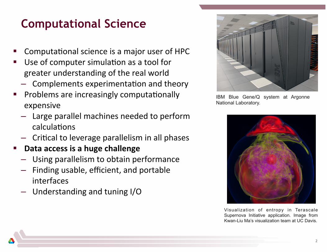
§ Computa8onal science is a major user of HPC § Use of computer simula8on as a tool for
greater understanding of the real world – Complements experimenta8on and theory
§ Problems are increasingly computa8onally expensive
– Large parallel machines needed to perform calcula8ons
– Cri8cal to leverage parallelism in all phases § Data access is a huge challenge
– Using parallelism to obtain performance – Finding usable, efficient, and portable
interfaces – Understanding and tuning I/O
Visualization of entropy in Terascale Supernova Initiative application. Image from Kwan-Liu Ma’s visualization team at UC Davis.
IBM Blue Gene/Q system at Argonne National Laboratory.
2

Outline
Today we will discuss HPC I/O systems, talk about some important concepts, look at some recent developments.
§ Material derived from “HPC I/O for Computa8onal Scien8sts” tutorial, presented earlier this year at ATPESC 2013
§ Topics: – Overview of HPC I/O systems
• Users • SoUware layers • Performance and op8miza8on
– Replacing the File Storage Model – Burst Buffers (maybe, depending on 8me)
§ Interrupt whenever, goal is to have a good discussion, not necessarily get through every slide.
3
Thinking about HPC I/O Systems
HPC I/O Systems
HPC I/O system is the hardware and soBware that assists in accessing data during simulaCons and analysis and retaining data between these acCviCes. § Hardware: disks, disk enclosures, servers, networks, etc. § SoUware: parallel file system, libraries, parts of the OS
§ Two “flavors” of I/O from applica8ons: – Defensive: storing data to protect results from data loss due to system
faults (i.e., checkpoint and restart) – ProducCve: storing/retrieving data as part of the scien8fic workflow – Note: Some8mes these are combined (i.e., data stored both protects
from loss and is used in later analysis) § “Flavor” influences priori8es:
– Defensive I/O: Spend as li_le 8me as possible – Produc8ve I/O: Capture provenance, organize for analysis
5

Data Volumes in Computational Science
Science teams are rouCnely working with tens and hundreds of terabytes (TBs) of data.
PI Project On-‐line Data
(TBytes) Off-‐line Data
(TBytes) Lamb Supernovae Astrophysics 100 400 Khokhlov Combus8on in Reac8ve Gases 1 17 Lester CO2 Absorp8on 5 15 Jordan Seismic Hazard Analysis 600 100 Washington Climate Science 200 750 Voth Energy Storage Materials 10 10 Vashista Stress Corrosion Cracking 12 72 Vary Nuclear Structure and Reac8ons 6 30 Fischer Reactor Thermal Hydraulic Modeling 100 100 Hinkel Laser-‐Plasma Interac8ons 60 60 Elghobashi Vaporizing Droplets in a Turbulent Flow 2 4
Data requirements for select 2012 INCITE applicaCons at ALCF (BG/P)
6
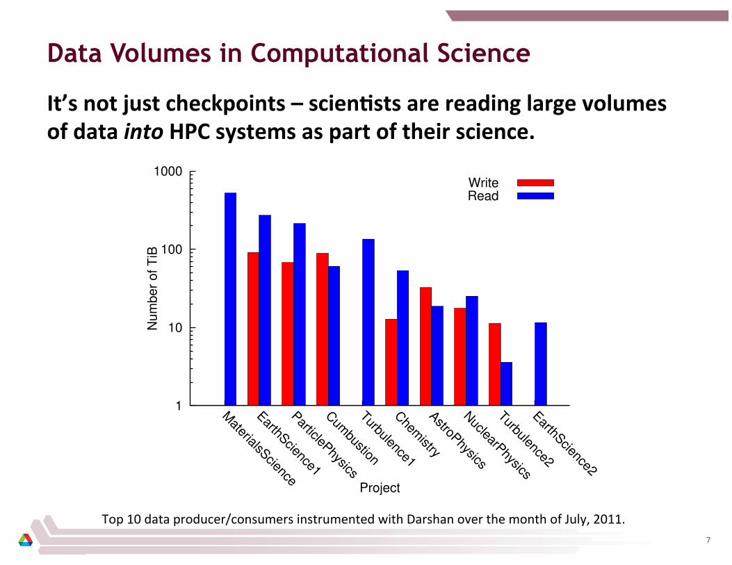
Data Volumes in Computational Science
It’s not just checkpoints – scienCsts are reading large volumes of data into HPC systems as part of their science.
1
10
100
1000
MaterialsScience
EarthScience1
ParticlePhysics
Cum
bustion
Turbulence1
Chem
istry
AstroPhysics
NuclearPhysics
Turbulence2
EarthScience2
Nu
mb
er
of
TiB
Project
Write���Read���
Top 10 data producer/consumers instrumented with Darshan over the month of July, 2011. 7

Data Complexity in Computational Science
§ Applica8ons have data models appropriate to domain
– Mul8dimensional typed arrays, images composed of scan lines, …
– Headers, a_ributes on data
§ I/O systems have very simple data models
– Tree-‐based hierarchy of containers – Some containers have streams of bytes
(files) – Others hold collec8ons of other
containers (directories or folders)
§ Mapping from one to the other is increasingly complex.
Right Interior Carotid Artery
Platelet Aggregation
Model complexity: Spectral element mesh (top) for thermal hydraulics computation coupled with finite element mesh (bottom) for neutronics calculation.
Scale complexity: Spatial range from the reactor core in meters to fuel pellets in millimeters. Images from T. Tautges (ANL) (upper left), M. Smith
(ANL) (lower left), and K. Smith (MIT) (right).
8
Views of Data Access in HPC Systems
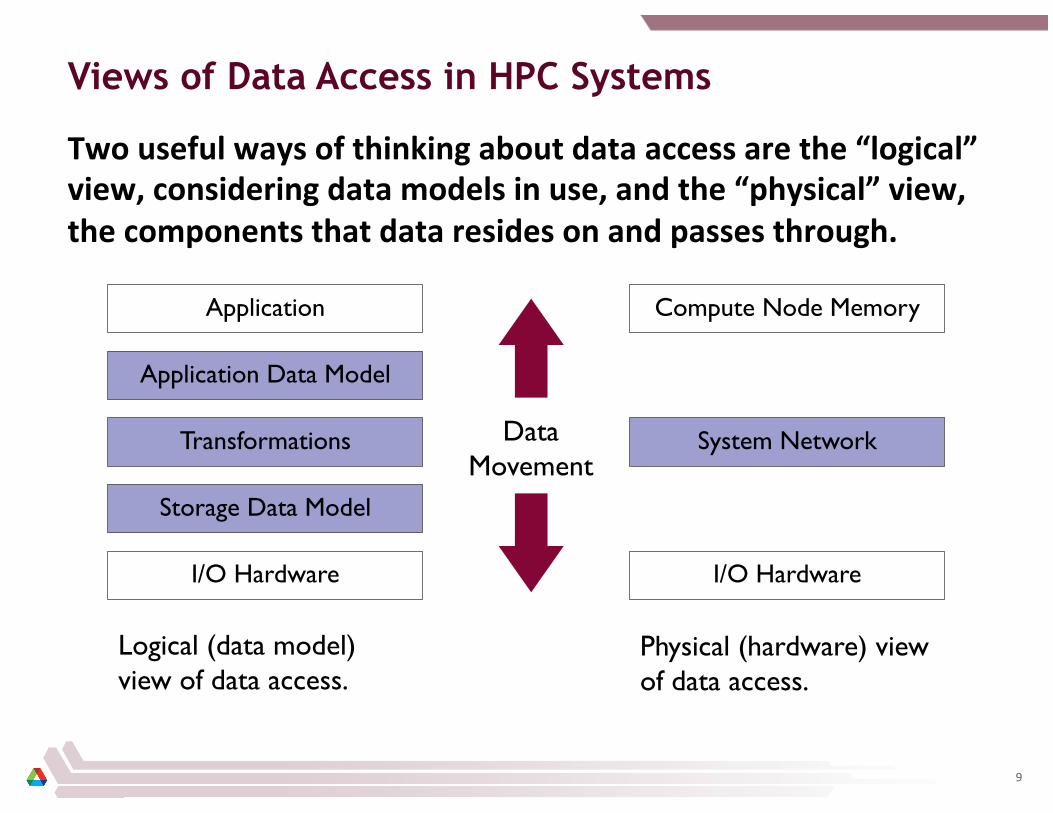
Two useful ways of thinking about data access are the “logical” view, considering data models in use, and the “physical” view, the components that data resides on and passes through.
I/O Hardware
Application
Storage Data Model
Transformations
Application Data Model
I/O Hardware
Compute Node Memory
System Network Data Movement
Logical (data model) view of data access.
Physical (hardware) view of data access.
9
Data Access in Past HPC Systems*
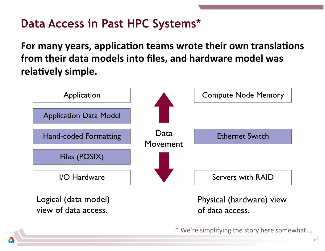
For many years, applicaCon teams wrote their own translaCons from their data models into files, and hardware model was relaCvely simple.
I/O Hardware
Application
Files (POSIX)
Hand-coded Formatting
Application Data Model
Servers with RAID
Compute Node Memory
Ethernet Switch Data Movement
Logical (data model) view of data access.
Physical (hardware) view of data access.
* We’re simplifying the story here somewhat … 10

Data Access in Current Large-scale Systems
Current systems have greater support on the logical side, more complexity on the physical side.
I/O Hardware
Application
Files (POSIX)
I/O Transform Layer(s)
Data Model Library
SAN and RAID Enclosures
Compute Node Memory
Internal System Network(s)
Data Movement
Logical (data model) view of data access.
Physical (hardware) view of data access.
I/O Gateways
External Sys. Network(s)
I/O Servers
11
Thinking about HPC I/O Systems
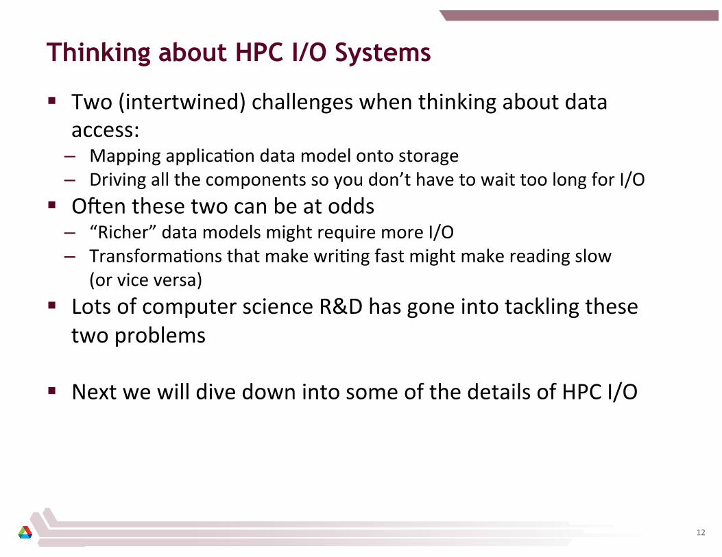
§ Two (intertwined) challenges when thinking about data access:
– Mapping applica8on data model onto storage – Driving all the components so you don’t have to wait too long for I/O
§ OUen these two can be at odds – “Richer” data models might require more I/O – Transforma8ons that make wri8ng fast might make reading slow
(or vice versa) § Lots of computer science R&D has gone into tackling these
two problems
§ Next we will dive down into some of the details of HPC I/O
12

How It Works: HPC I/O Systems
How It Works
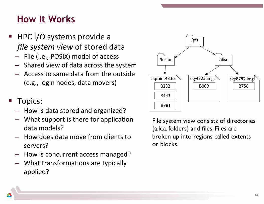
§ HPC I/O systems provide a file system view of stored data
– File (i.e., POSIX) model of access – Shared view of data across the system – Access to same data from the outside
(e.g., login nodes, data movers)
§ Topics: – How is data stored and organized? – What support is there for applica8on
data models? – How does data move from clients to
servers? – How is concurrent access managed? – What transforma8ons are typically
applied?
File system view consists of directories (a.k.a. folders) and files. Files are broken up into regions called extents or blocks.
14
Storing and Organizing Data: Storage Model
HPC I/O systems are built around a parallel file system that organizes storage and manages access. § Parallel file systems (PFSes) are distributed systems that
provide a file data model (i.e., files and directories) to users § Mul8ple PFS servers manage access to storage, while PFS
client systems run applica8ons that access storage § PFS clients can access storage resources in parallel!
15
Reading and Writing Data (etc.)
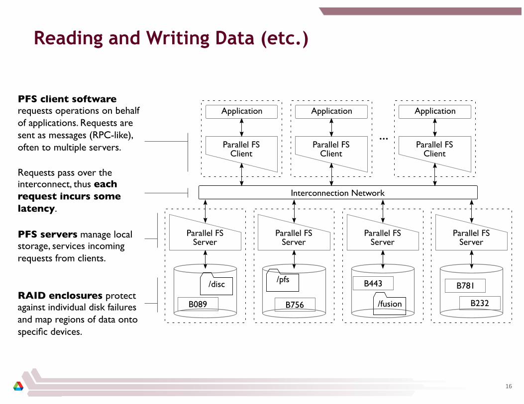
PFS servers manage local storage, services incoming requests from clients.
PFS client software requests operations on behalf of applications. Requests are sent as messages (RPC-like), often to multiple servers.
Requests pass over the interconnect, thus each request incurs some latency.
RAID enclosures protect against individual disk failures and map regions of data onto specific devices.
16

Leadership Systems have an additional HW layer
Compute nodes run application processes. Data model software also runs here, and some I/O transformations are performed here.
I/O forwarding nodes (or I/O gateways) shuffle data between compute nodes and external resources, including storage.
Storage nodes run the parallel file system.
External network
Disk arrays
17
Request Size and I/O Rate
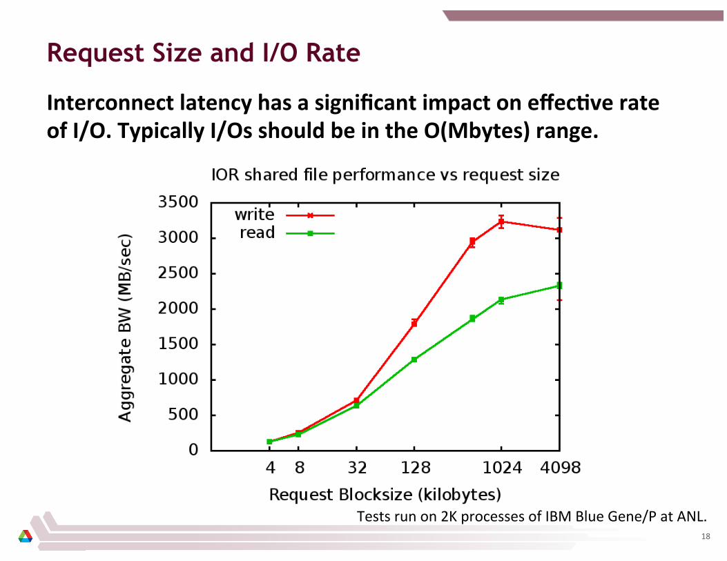
Interconnect latency has a significant impact on effecCve rate of I/O. Typically I/Os should be in the O(Mbytes) range.
Tests run on 2K processes of IBM Blue Gene/P at ANL. 18
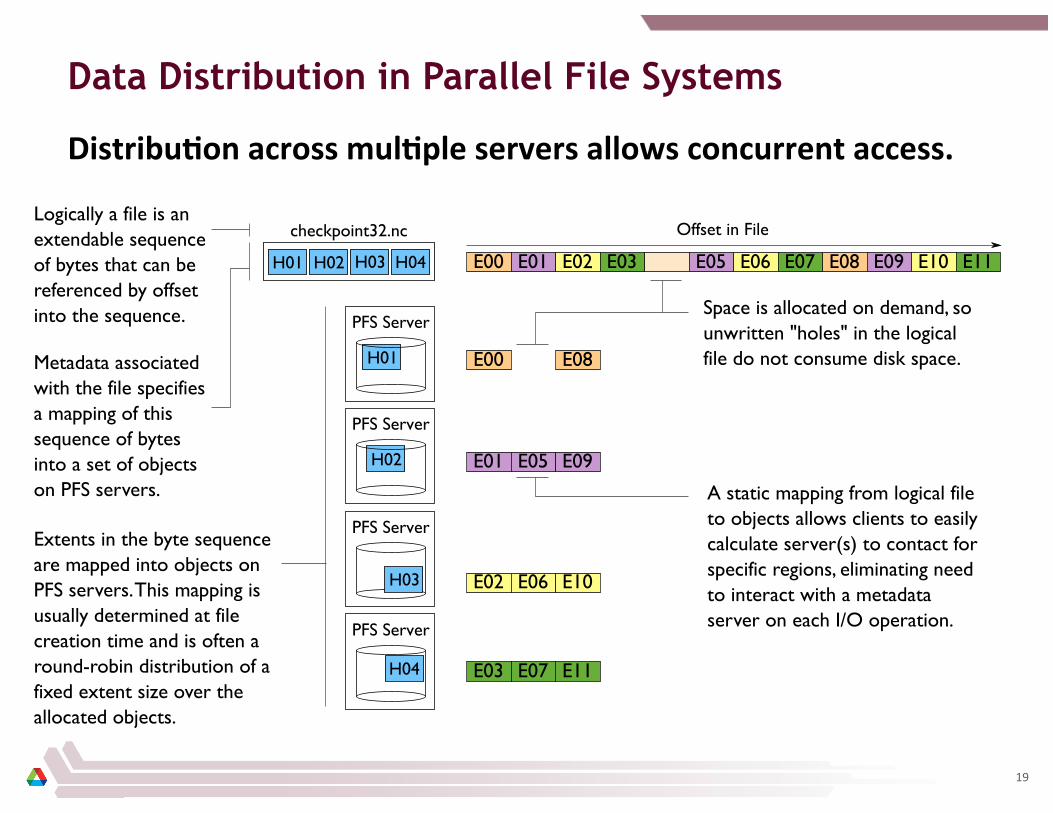
Data Distribution in Parallel File Systems
DistribuCon across mulCple servers allows concurrent access.
19
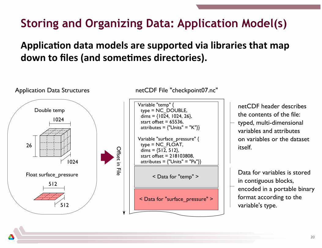
Storing and Organizing Data: Application Model(s)
ApplicaCon data models are supported via libraries that map down to files (and someCmes directories).
20

HPC I/O Software Stack
The soBware used to provide data model support and to transform I/O to be]er perform on today’s I/O systems is oBen referred to as the I/O stack.
Data Model Libraries map application abstractions onto storage abstractions and provide data portability.
HDF5, Parallel netCDF, ADIOS
I/O Middleware organizes accesses from many processes, especially those using collective ���I/O.
MPI-IO, GLEAN, PLFS I/O Forwarding transforms I/O from many clients into fewer, larger request; reduces lock contention; and bridges between the HPC system and external storage.
IBM ciod, IOFSL, Cray DVS
Parallel file system maintains logical file model and provides efficient access to data.
PVFS, PanFS, GPFS, Lustre I/O Hardware
Application
Parallel File System
Data Model Support
Transformations
21
How It Works: HPC I/O Performance
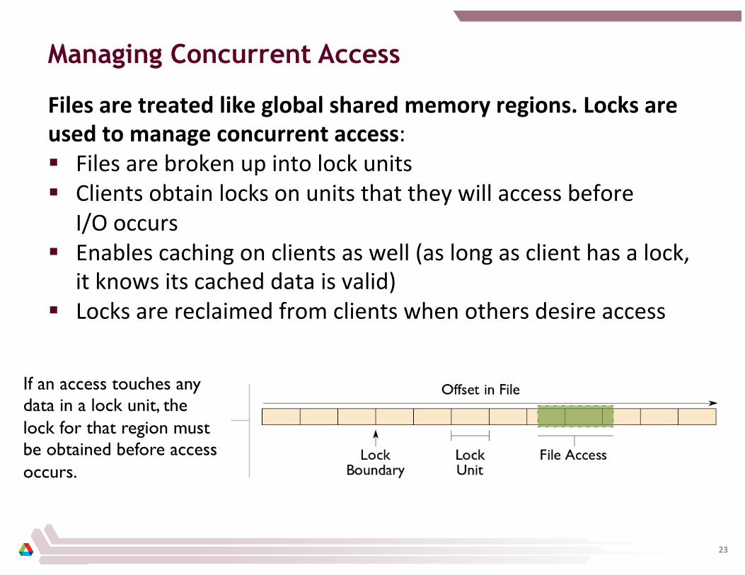
Managing Concurrent Access
Files are treated like global shared memory regions. Locks are used to manage concurrent access: § Files are broken up into lock units § Clients obtain locks on units that they will access before
I/O occurs § Enables caching on clients as well (as long as client has a lock,
it knows its cached data is valid) § Locks are reclaimed from clients when others desire access
If an access touches any data in a lock unit, the lock for that region must be obtained before access occurs.
23
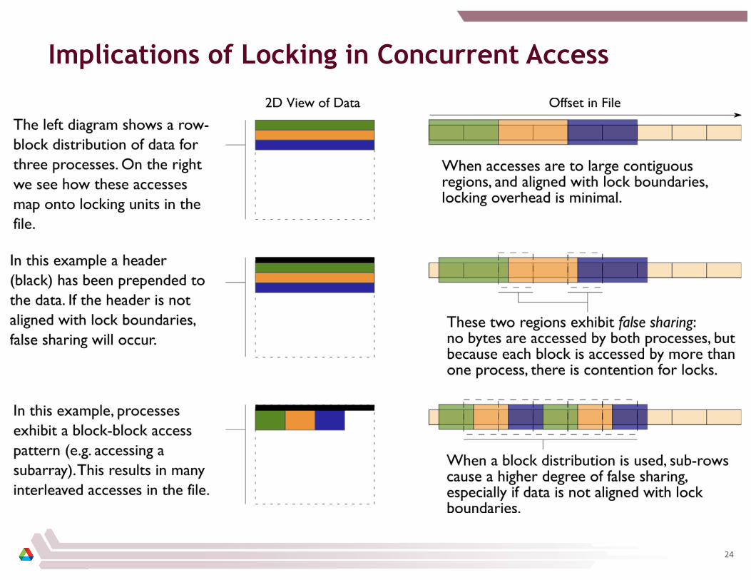
Implications of Locking in Concurrent Access
24
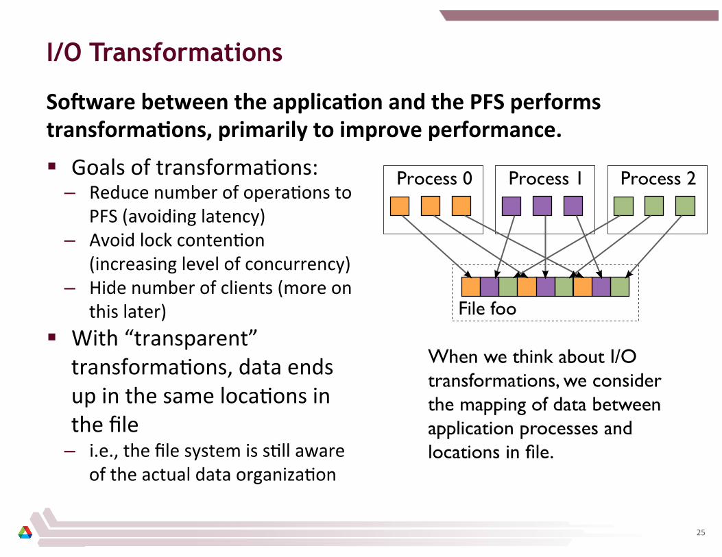
I/O Transformations
SoBware between the applicaCon and the PFS performs transformaCons, primarily to improve performance.
§ Goals of transforma8ons: – Reduce number of opera8ons to
PFS (avoiding latency) – Avoid lock conten8on
(increasing level of concurrency) – Hide number of clients (more on
this later) § With “transparent”
transforma8ons, data ends up in the same loca8ons in the file
– i.e., the file system is s8ll aware of the actual data organiza8on
When we think about I/O transformations, we consider the mapping of data between application processes and locations in file.
25

Reducing Number of Operations
Since most operaCons go over the network, I/O to a PFS incurs more latency than with a local FS. Data sieving is a technique to address I/O latency by combining opera8ons: § When reading, applica8on process reads a large region
holding all needed data and pulls out what is needed § When wri8ng, three steps required (below)
Step 1: Data in region to be modified are read into intermediate buffer (1 read).
Step 2: Elements to be written to file are replaced in intermediate buffer.
Step 3: Entire region is written back to storage with a single write operation.
26

Avoiding Lock Contention
To avoid lock contenCon when wriCng to a shared file, we can reorganize data between processes. Two-‐phase I/O splits I/O into a data reorganiza8on phase and an interac8on with the storage system (two-‐phase write depicted): § Data exchanged between processes to match file layout § 0th phase determines exchange schedule (not shown)
Phase 1: Data are exchanged between processes based on organization of data in file.
Phase 2: Data are written to file (storage servers) with large writes, no contention.
27

Two-Phase I/O Algorithms (or, You don’t want to do this yourself…)
For more information, see W.K. Liao and A. Choudhary, “Dynamically Adapting File Domain Partitioning Methods for Collective I/O Based on Underlying Parallel File System Locking Protocols,” SC2008, November, 2008.
28

S3D Turbulent Combustion Code
§ S3D is a turbulent combus8on applica8on using a direct numerical simula8on solver from Sandia Na8onal Laboratory
§ Checkpoints consist of four global arrays
– 2 3-‐dimensional – 2 4-‐dimensional – 50x50x50 fixed
subarrays
Thanks to Jackie Chen (SNL), Ray Grout (SNL), and Wei-Keng Liao (NWU) for providing the S3D I/O benchmark, Wei-Keng Liao for providing this diagram, C. Wang, H. Yu, and K.-L. Ma of UC Davis for image.
29
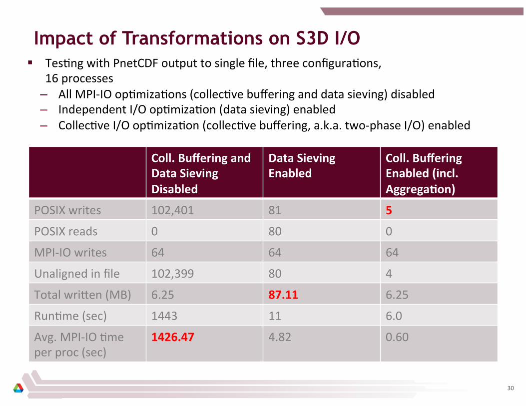
Impact of Transformations on S3D I/O § Tes8ng with PnetCDF output to single file, three configura8ons,
16 processes – All MPI-‐IO op8miza8ons (collec8ve buffering and data sieving) disabled – Independent I/O op8miza8on (data sieving) enabled – Collec8ve I/O op8miza8on (collec8ve buffering, a.k.a. two-‐phase I/O) enabled
Coll. Buffering and Data Sieving Disabled
Data Sieving Enabled
Coll. Buffering Enabled (incl. AggregaCon)
POSIX writes 102,401 81 5
POSIX reads 0 80 0
MPI-‐IO writes 64 64 64
Unaligned in file 102,399 80 4
Total wri_en (MB) 6.25 87.11 6.25
Run8me (sec) 1443 11 6.0
Avg. MPI-‐IO 8me per proc (sec)
1426.47 4.82 0.60
30
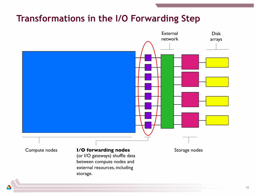
Transformations in the I/O Forwarding Step
Compute nodes I/O forwarding nodes (or I/O gateways) shuffle data between compute nodes and external resources, including storage.
Storage nodes
External network
Disk arrays
31
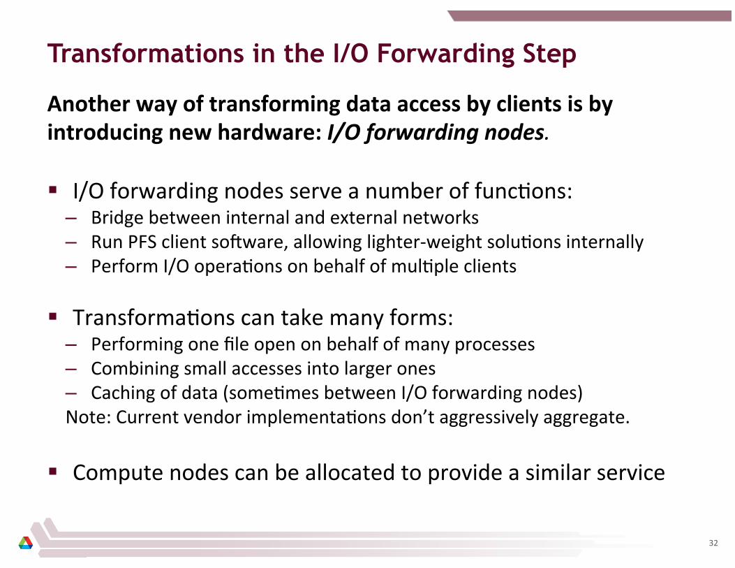
Transformations in the I/O Forwarding Step
Another way of transforming data access by clients is by introducing new hardware: I/O forwarding nodes. § I/O forwarding nodes serve a number of func8ons:
– Bridge between internal and external networks – Run PFS client soUware, allowing lighter-‐weight solu8ons internally – Perform I/O opera8ons on behalf of mul8ple clients
§ Transforma8ons can take many forms: – Performing one file open on behalf of many processes – Combining small accesses into larger ones – Caching of data (some8mes between I/O forwarding nodes) Note: Current vendor implementa8ons don’t aggressively aggregate.
§ Compute nodes can be allocated to provide a similar service
32
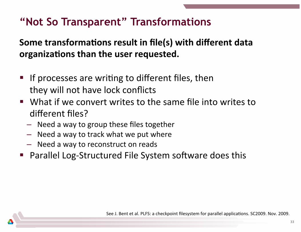
“Not So Transparent” Transformations
Some transformaCons result in file(s) with different data organizaCons than the user requested.
§ If processes are wri8ng to different files, then they will not have lock conflicts
§ What if we convert writes to the same file into writes to different files?
– Need a way to group these files together – Need a way to track what we put where – Need a way to reconstruct on reads
§ Parallel Log-‐Structured File System soUware does this
See J. Bent et al. PLFS: a checkpoint filesystem for parallel applica8ons. SC2009. Nov. 2009. 33
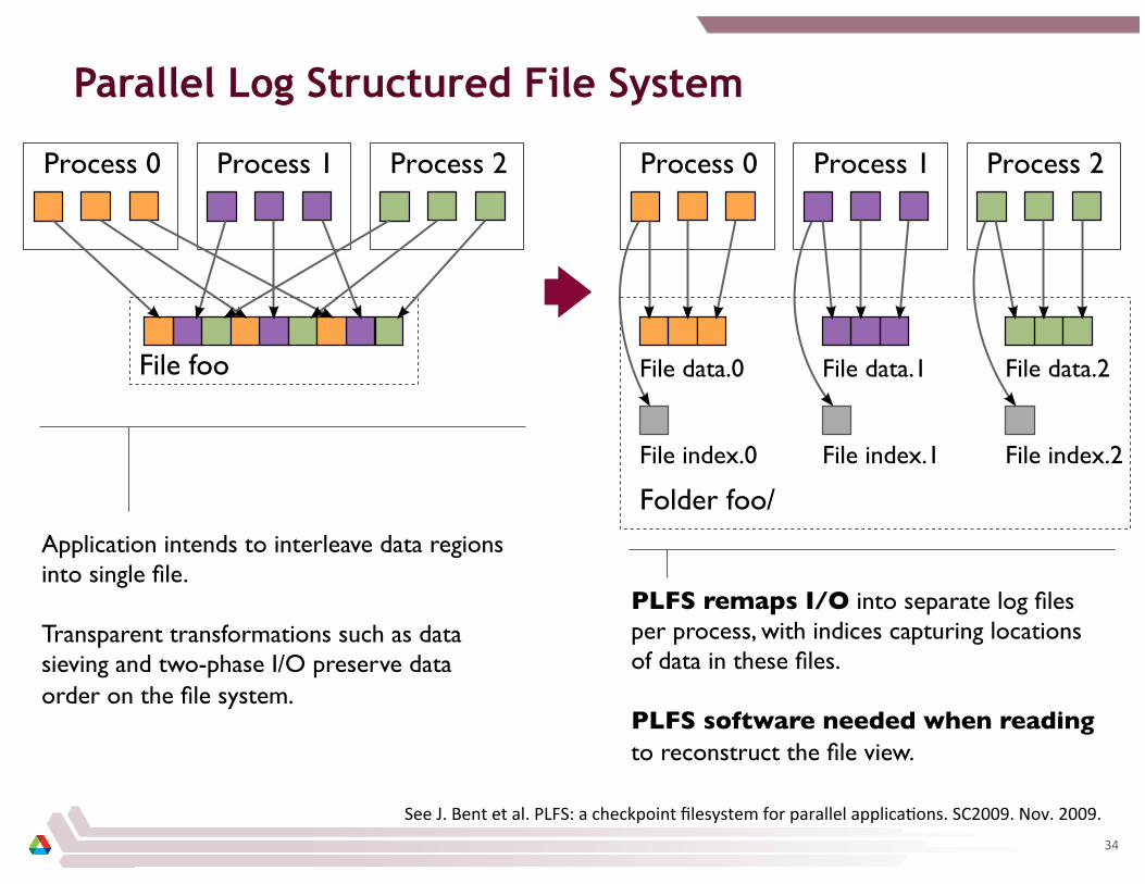
Parallel Log Structured File System
See J. Bent et al. PLFS: a checkpoint filesystem for parallel applica8ons. SC2009. Nov. 2009.
Application intends to interleave data regions into single file. Transparent transformations such as data sieving and two-phase I/O preserve data order on the file system.
PLFS remaps I/O into separate log files per process, with indices capturing locations of data in these files. PLFS software needed when reading to reconstruct the file view.
34
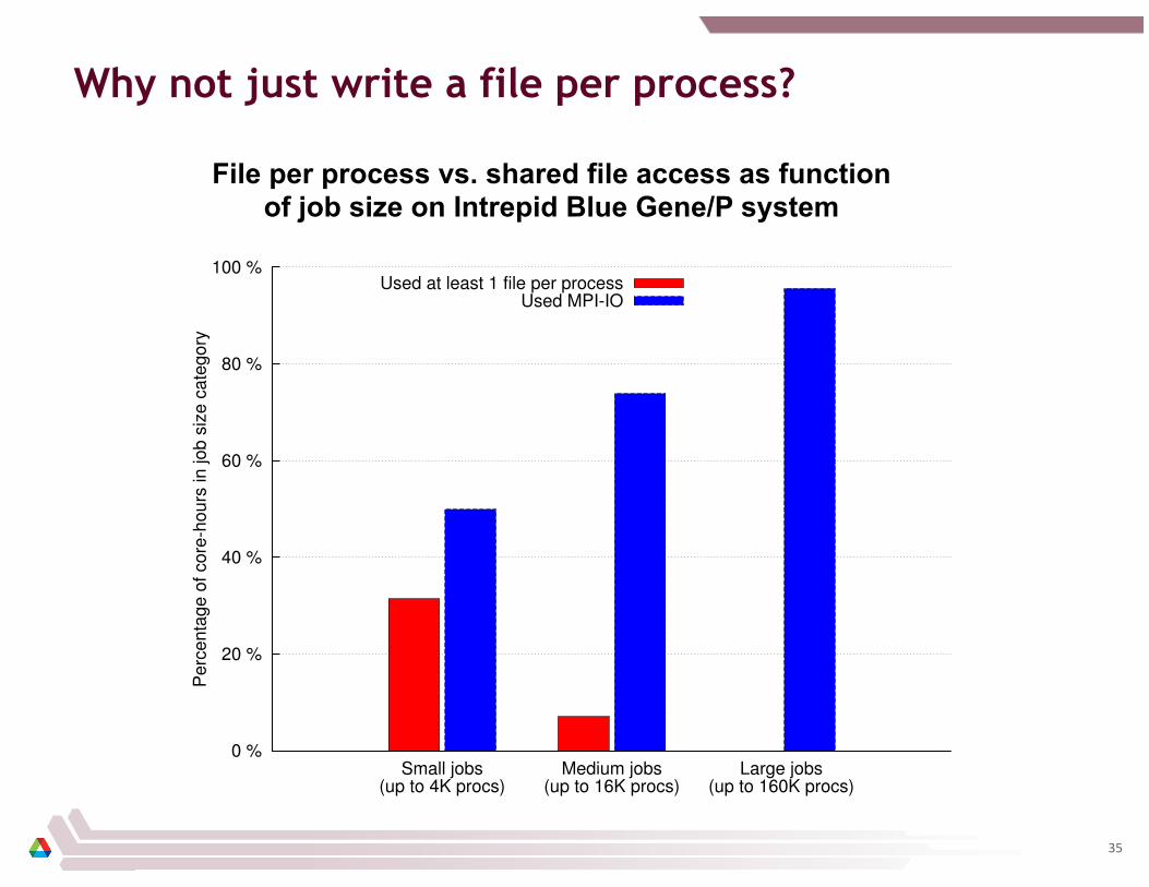
Why not just write a file per process?
0 %
20 %
40 %
60 %
80 %
100 %
Small jobs(up to 4K procs)
Medium jobs(up to 16K procs)
Large jobs(up to 160K procs)
Perc
enta
ge o
f co
re-h
ours
in jo
b s
ize c
ate
gory
Used at least 1 file per processUsed MPI-IO
File per process vs. shared file access as function of job size on Intrepid Blue Gene/P system
35

I/O Transformations and the Storage Data Model
Historically, the storage data model has been the POSIX file model, and the PFS has been responsible for managing it.
§ Transparent transforma8ons work within these limita8ons § When data model libraries are used:
– Transforms can take advantage of more knowledge • e.g., dimensions of mul8dimensional datasets
– Doesn’t ma_er so much whether there is a single file underneath – Or in what order the data is stored – As long as portability is maintained
§ Single stream of bytes in a file is inconvenient for parallel access
– Later will discuss efforts to provide a different underlying model
36

Replacing the File Storage Model
Many thanks to: Dave Goodell Cisco Systems
Shawn Kim Penn State University
Mahmut Kandemir Penn State University
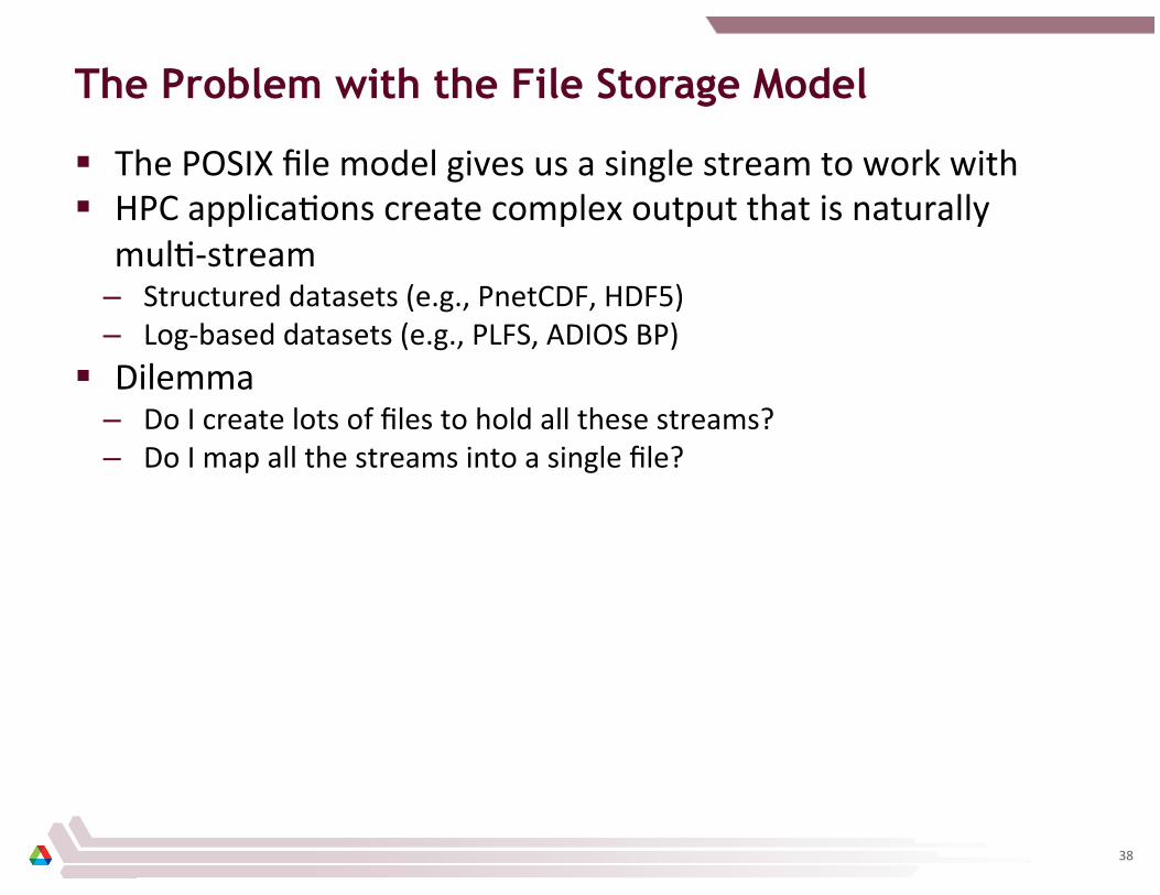
The Problem with the File Storage Model
§ The POSIX file model gives us a single stream to work with § HPC applica8ons create complex output that is naturally
mul8-‐stream – Structured datasets (e.g., PnetCDF, HDF5) – Log-‐based datasets (e.g., PLFS, ADIOS BP)
§ Dilemma – Do I create lots of files to hold all these streams? – Do I map all the streams into a single file?
38

Recall: Data Distribution in Parallel File Systems Modern parallel file systems internally manage mulCple data streams; they just aren’t exposed to the user.
39

An Alternative Storage Model
§ Expose individual object streams for use by users and I/O libraries
– Users/libraries become responsible for mapping of data to objects § Keep the name space as it is
– Directories, file names, permissions
§ General approach is being pursued by the Intel Fast Forward team (Intel, EMC, HDF5 Group) and also by ANL/Penn State
40
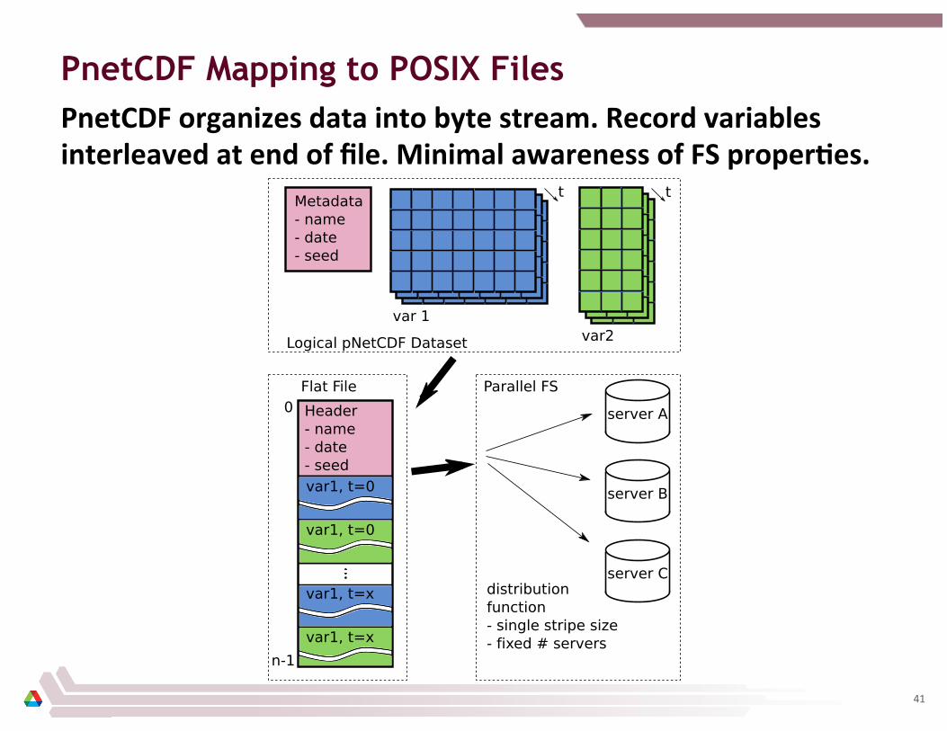
PnetCDF Mapping to POSIX Files
41
PnetCDF organizes data into byte stream. Record variables interleaved at end of file. Minimal awareness of FS properCes.

PnetCDF Mapping to Alternative Storage Model
42
Variables mapped into disCnct objects. Resizing of one variable has no impact on others.
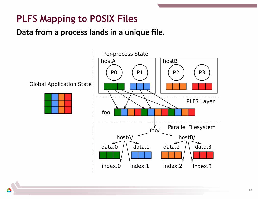
PLFS Mapping to POSIX Files
43
Data from a process lands in a unique file.
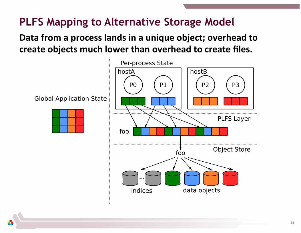
PLFS Mapping to Alternative Storage Model
44
Data from a process lands in a unique object; overhead to create objects much lower than overhead to create files.
Other Interesting Ideas
§ Lots of alterna8ves being kicked around in various contexts: – Record-‐oriented storage – Forks – Search / alternaCve name spaces – Versioning storage
§ Our hope is that we see a standard replacement emerge for shared block storage and the file system model
45

Wrapping Up

Wrapping Up
§ HPC storage is a complex hardware/soUware system § Principles used in op8miza8on are applicable outside HPC
– Aggrega8on – Transforma8on to match requirements of devices – Avoidance of conten8on
§ New storage models are being developed – Exposing concurrency in storage system
§ Generally HPC storage evolu8on has been slow, needs to catch up with data intensive storage systems!
47
Many thanks to: Ning Liu Illinois Ins8tute of Technology
Chris Carothers Rensselear Polytechnic Ins8tute
Jason Cope DataDirect Networks
In-System Storage
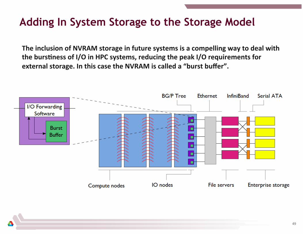
Adding In System Storage to the Storage Model
The inclusion of NVRAM storage in future systems is a compelling way to deal with the bursCness of I/O in HPC systems, reducing the peak I/O requirements for external storage. In this case the NVRAM is called a “burst buffer”.
49
What’s a Burst?
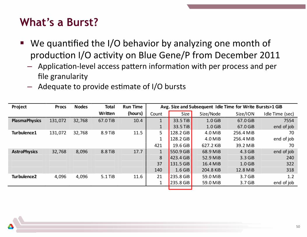
§ We quan8fied the I/O behavior by analyzing one month of produc8on I/O ac8vity on Blue Gene/P from December 2011
– Applica8on-‐level access pa_ern informa8on with per process and per file granularity
– Adequate to provide es8mate of I/O bursts
Project Procs Nodes Total Written
Run Time (hours)
Avg. Size and Subsequent Idle Time for Write Bursts>1 GiB Count Size Size/Node Size/ION Idle Time (sec)
PlasmaPhysics 131,072 32,768 67.0 TiB 10.4 1 33.5 TiB 1.0 GiB 67.0 GiB 7554 1 33.5 TiB 1.0 GiB 67.0 GiB end of job
Turbulence1 131,072 32,768 8.9 TiB 11.5 5 128.2 GiB 4.0 MiB 256.4 MiB 70 1 128.2 GiB 4.0 MiB 256.4 MiB end of job 421 19.6 GiB 627.2 KiB 39.2 MiB 70 AstroPhysics 32,768 8,096 8.8 TiB 17.7 1 550.9 GiB 68.9 MiB 4.3 GiB end of job 8 423.4 GiB 52.9 MiB 3.3 GiB 240 37 131.5 GiB 16.4 MiB 1.0 GiB 322 140 1.6 GiB 204.8 KiB 12.8 MiB 318 Turbulence2 4,096 4,096 5.1 TiB 11.6 21 235.8 GiB 59.0 MiB 3.7 GiB 1.2 1 235.8 GiB 59.0 MiB 3.7 GiB end of job
50

Studying Burst Buffers with Parallel Discrete Event Simulation
51
Burst Buffers Work for Multi-application Workloads
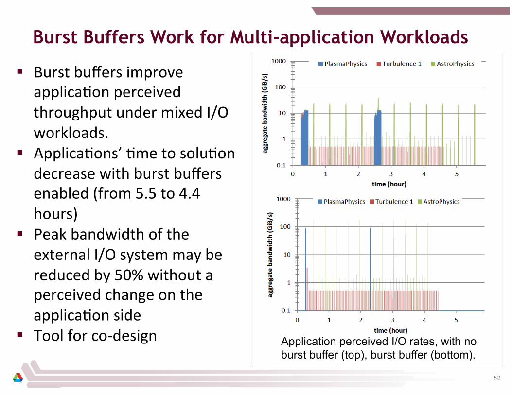
§ Burst buffers improve applica8on perceived throughput under mixed I/O workloads.
§ Applica8ons’ 8me to solu8on decrease with burst buffers enabled (from 5.5 to 4.4 hours)
§ Peak bandwidth of the external I/O system may be reduced by 50% without a perceived change on the applica8on side
§ Tool for co-‐design Application perceived I/O rates, with no burst buffer (top), burst buffer (bottom).
52

Beyond Burst Buffers
§ Obviously lots of other poten8al uses – Checkpoin8ng loca8on – Out-‐of-‐core computa8on – Holding area for analysis data (e.g., temporal analysis, in situ) – Code coupling – Input data staging – …
§ Improves memory capacity of systems – More data intensive applica8ons?
§ Placement of NVRAM will ma_er – On I/O forwarding nodes (as in our example) – On some/all compute nodes?
53