high performance induction motor drive based on adaptive variable...
TRANSCRIPT

Journal of ELECTRICAL ENGINEERING, VOL. 56, NO. 3-4, 2005, 64–70
HIGH PERFORMANCE INDUCTION MOTOR DRIVE BASEDON ADAPTIVE VARIABLE STRUCTURE CONTROL
Elwy E. El-kholy∗
A new approach to control system design for induction motor drive is presented. The control method is based on adaptivevariable structure design. The mathematical model of the adaptive variable structure controller based on Genetic algorithmsystem is presented. The design is simple and easy to be implemented. Simulation and experimental results show that theproposed adaptive variable structure controller provides high performance dynamic characteristics and is robust with regard
to change of motor speed and external load disturbance.
K e y w o r d s: variable structure control, AC drives, induction motor, genetic algorithm
1 INTRODUCTION
Recently, advanced control strategies for PWM in-verter fed induction motor drive has been presented. Par-ticularly, the vector control, which guarantees high dy-namic and static performances like DC motor drives, hasbecome very popular and has been developed and im-proved. Recent developments in the theory of vector con-trol, fast digital processor and power devices provide thepossibility of achieving high performance induction mo-tor drive control. There are many works devoted to thevector control, but only few deals with the improving theperformance of controller structure [1, 2].
Conventional Proportional-Integral (PI) controllers,designed using the classical control theory, are well suitedto the control of linear processes whose exact model isknown. However, the majority of physical systems usuallycontain non-linear relations that are difficult to model.On the other hand, to use a self-tuning PI controller,an adequate drive model must be known [3, 4]. As it iswell known by linear control theory, the design PI con-troller procedure consists in tuning their parameters inorder to achieve the required bandwidth and disturbancerejection. A quite precise knowledge of motor and loadparameters is thus required. This condition cannot be al-ways satisfied because some parameters are not exactlyknown and/or are subject to variations during operation.As a consequence of this phenomenon a degradation ofthe drive performance occurs. To avoid these problems,different non-linear control strategies have been proposedin the literature [5–8]. Control structure based on artifi-cial intelligence, such as artificial neural network, fuzzylogic, and variable structure controller (VSC) appears tobe an advantageous solution for control of such processes[9–11].
The variable structure system is inherently aimed atdealing with system uncertainties, lead to good perfor-
mances even in presence of strong and fast variations ofthe motor parameters. The theory of variable structuresystems with a sliding mode has been studied by manyresearchers [1–11]. The basic principle of VSC consistsin enforcing the system motion to occur on a prescribedmanifold in the state space, which is defined according tothe control tasks. The most significant property of a VSCis: its robustness, insensitivity to parameter variations,fast dynamic response.
In this paper a VSC via genetic algorithm (GA) isproposed for the speed control in the induction motordrive. The proposed VSC controller has some features forwhich the acceleration signal used in conventional vari-able structure speed control is not required, and onlythe speed signal is required in control law. The proposedVSC has some features for which the speed signal onlyis required in the control algorithm, and the transientresponse is improved. In addition, the robustness and ex-ponential convergence of the controlled speed are pro-vided. Finally, the simulation and experimental resultsare demonstrated.
2 VARIABLE STRUCTURE CONTROL
ALGORITHM DESCRIPTION
The VSC algorithm can be easily applied to a vec-tor controlled induction motor drive. In a sliding mode(SM) control, the reference model is stored in the formof a predefined phase plane trajectory, and the systemresponse is forced to follow or slide along the trajectoryby a switching control algorithm [1].
As aforementioned, the starting point of a sliding modecontrol design is the definition of the sliding surface orsliding line. The next stage is to drive a control algo-rithm to ensure that the system will be able to reach orcross the chosen sliding line. After the system crossing the
∗ Electrical Engineering Department, Faculty of Engineering, Menoufiya University, Shebin El-Kom, Egypt,
Kingdom of Saudia Arabia, Sukaka-Aljouf, Aljouf Technical Collage, P.O. 1642 E-mail: [email protected]
ISSN 1335-3632 c© 2005 FEI STU

Journal of ELECTRICAL ENGINEERING 56, NO. 3–4, 2005 65
3 phase
AC supply
Torque and flux
control
Voltage
source
inverter
IM
Incremental
encoder
Motor speed (ωr)
ωerr-+
Rectifier VSI
Variable structure
speed controller
Current
controller
∗Speed command (ωr )
Induction
motor
Fig. 1. Configuration of the control system
sliding line, it will be able to cross it again for an infinitenumber of times. In this paper, the motor speed is con-trolled in order to obtain a constant motor speed. So, thevector control task is to impose the convergence of themotor speed magnitude to a reference one. This goal canbe fulfilled applying the VSC synthesis procedure to theerror speed system equation. The block diagram of thevector control with speed controller is shown in Fig. 1.
The error ωerr between the motor speed and its ref-erence can be obtained as follows;
ωerr(t) = ω∗
r (t) − ωr(t) (1)
and its derivative can be obtained as [2];
ω0
err(t) =
(
−B
J+
3p
2
Lm
Lr
k
)
ωerr(t) . (2)
Where, k is a linear feedback-gain, B is the viscousfriction, J is the moment of inertia, p is the number ofpair poles, Lm is the mutual inductance, and Lr is theself inductance of the rotor per phase of the inductionmotor.
So, the equivalent dynamic behavior of control systemcan be rewritten as [2];
ω0
err(t) = (a + bk)ωerr(t) (3)
where, a = −B/J , b = 3p/2. Lm/Lr , k is a feedbackgain, and (a + bk) is designed to be strictly negative.
The switching surface with an integral component forthe sliding mode speed controller is designed as follows[2];
S(t) = ωerr(t) −
∫ t
0
(a + bk)ωerr(τ)dτ . (4)
It is obvious from the equation (3) that the speed errorwill converge to zero exponentially if the pole of the sys-tem is strategically located on the left-hand plane. Thus,the overshoot phenomenon will not occur, and the systemdynamic will behave as a state feedback control system.
Based on the developed switching surface, a switchingcontrol law, which satisfies the hitting condition and guar-antees the existence of the sliding mode is then designed.So, the variable structure speed controller is designed asthe following,
Isq (t) = kωerr(t) − β sgn
(
S(t))
(5)
Rectifier Inverter
3 phase AC supply
2/3phases
transformation
Switching
generation
Adaptive
VSC speed
controller
Rotating to
stationary
transformation
Slip
generator
IM
iqs
Incremental
encoder
ids
Genetic
optimized
algorithm
Limiter
ωr∗
ωr
ωr∗
-
+
+
+
Field weakening
control
∫
∫
K & β
Fig. 2. GA-optimized VSC for vector controlled induction motor drive
66 E. E. El-kholy: HIGH PERFORMANCE INDUCTION MOTOR DRIVE BASED ON ADAPTIVE VARIABLE STRUCTURE CONTROL . . .
0 0.1 0.2 0.3 0.4 0.50
50
100
150
Motor speed (rad/s)
Time (s)
a)
0 0.1 0.2 0.3 0.4 0.5-10
-5
0
5
10
Time (s)
Current (A)
b)
0.4 0.42 0.44 0.46 0.48 0.5-4
-2
0
2
4
Time (s)
Current (A)
c)
0 0.1 0.2 0.3 0.4 0.5-10
0
10
20
30
Time (s)
Torque (Nm)
d)
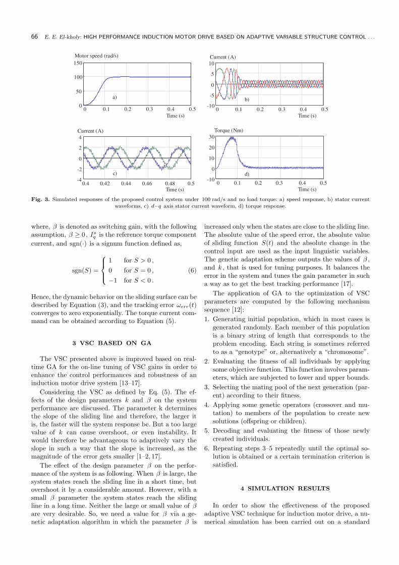
Fig. 3. Simulated responses of the proposed control system under 100 rad/s and no load torque: a) speed response, b) stator current
waveforms, c) d–q axis stator current waveform, d) torque response.
where, β is denoted as switching gain, with the followingassumption, β ≥ 0, Is
q is the reference torque component
current, and sgn(·) is a signum function defined as,
sgn(S) =
1 for S > 0 ,
0 for S = 0 ,
−1 for S < 0 .
(6)
Hence, the dynamic behavior on the sliding surface can bedescribed by Equation (3), and the tracking error ωerr(t)converges to zero exponentially. The torque current com-mand can be obtained according to Equation (5).
3 VSC BASED ON GA
The VSC presented above is improved based on real-time GA for the on-line tuning of VSC gains in order toenhance the control performances and robustness of aninduction motor drive system [13–17].
Considering the VSC as defined by Eq. (5). The ef-fects of the design parameters k and β on the systemperformance are discussed. The parameter k determinesthe slope of the sliding line and therefore, the larger itis, the faster will the system response be. But a too largevalue of k can cause overshoot, or even instability. Itwould therefore be advantageous to adaptively vary theslope in such a way that the slope is increased, as themagnitude of the error gets smaller [1–2, 17].
The effect of the design parameter β on the perfor-mance of the system is as following. When β is large, thesystem states reach the sliding line in a short time, butovershoot it by a considerable amount. However, with asmall β parameter the system states reach the slidingline in a long time. Neither the large or small value of βare very desirable. So, we need a value for β via a ge-netic adaptation algorithm in which the parameter β is
increased only when the states are close to the sliding line.The absolute value of the speed error, the absolute valueof sliding function S(t) and the absolute change in thecontrol input are used as the input linguistic variables.The genetic adaptation scheme outputs the values of β ,and k , that is used for tuning purposes. It balances theerror in the system and tunes the gain parameter in sucha way as to get the best tracking performance [17].
The application of GA to the optimization of VSCparameters are computed by the following mechanismsequence [12]:
1. Generating initial population, which in most cases isgenerated randomly. Each member of this populationis a binary string of length that corresponds to theproblem encoding. Each string is sometimes referredto as a “genotype” or, alternatively a “chromosome”.
2. Evaluating the fitness of all individuals by applyingsome objective function. This function involves param-eters, which are subjected to lower and upper bounds.
3. Selecting the mating pool of the next generation (par-ent) according to their fitness.
4. Applying some genetic operators (crossover and mu-tation) to members of the population to create newsolutions (offspring or children).
5. Decoding and evaluating the fitness of those newlycreated individuals.
6. Repeating steps 3–5 repeatedly until the optimal so-lution is obtained or a certain termination criterion issatisfied.
4 SIMULATION RESULTS
In order to show the effectiveness of the proposedadaptive VSC technique for induction motor drive, a nu-merical simulation has been carried out on a standard

Journal of ELECTRICAL ENGINEERING 56, NO. 3–4, 2005 67
0 0.1 0.2 0.3 0.4 0.50
50
100
150
200
Time (s)
Motor speed (rad/s)
a)
0.4 0.42 0.44 0.46 0.48 0.5-5
0
5
Time (s)
Current (A)
b)
0.4 0.42 0.44 0.46 0.48 0.5-5
0
5
Time (s)
Current (A)
c)
0 0.1 0.2 0.3 0.4 0.50
10
20
30
Time (s)
Torque(Nm)
d)
Fig. 4. Proposed control system response under load torque 5 Nm and speed command 150 rad/s: a) speed response, b) stator currents,
c) d–q axis stator currents, d) torque response.
0 0.1 0.2 0.3 0.4 0.50
50
100
150
200
Time (s)
Motor speed (rad/s)
a)
0 0.1 0.2 0.3 0.4 0.5-10
-5
0
5
10
Time (s)
Current (A)
b)
Fig. 5. Simulated responses of the proposed control system due to step up change in speed command: a) speed response, b) three-phase
stator currents
0 0.1 0.2 0.3 0.4 0.50
50
100
150
200
Time (s)
Motor speed (rad/s)
a)
0 0.1 0.2 0.3 0.4 0.5-10
-5
0
5
10
Time (s)
Current (A)
b)
Fig. 6. Simulated responses of the proposed control system under step down change in speed command: a) speed response, b) three-phasestator currents
1.5 HP, 220/380 V, 50 Hz, 4-poles induction motor. Fig-ure 2, shows the GA optimized VSC for vector controlledinduction motor drive. The numerical simulation of theadaptive VSC based on real-time GA is given here.
Figure 3, indicates the simulated responses when themotor unloaded and speed command is 100 rad/s. Fig-ure 3a shows the speed response. It is noticed that thesteady-state value has been reached after about 0.14 s.Figure 3b shows the three-phase stator currents wave-form at starting and steady state. Figure 3c shows thestator currents waveform in the d -q axis. It is noticedthat the angle between them is nearly 90◦ and are al-
most sinusoidal. Figure 3d shows the developed motortorque response.
Simulated responses of the proposed control systemunder 100 rad/s and no load torque.
Figure 4 indicates the simulated responses when themotor is loaded by 5 N.m and speed command 150 rad/s.Figure 4a shows the speed response, It is noticed that thesteady-state value has been reached after about 0.23 s.Figure 4b shows the stator current waveforms at steadystate, which are nearly sinusoidal. Figure 4c shows thestator current waveforms in the d–q axis, where the an-gle between them is nearly 90◦ . It is noticed that the

68 E. E. El-kholy: HIGH PERFORMANCE INDUCTION MOTOR DRIVE BASED ON ADAPTIVE VARIABLE STRUCTURE CONTROL . . .
Vector control gate
pulse generator
D/A
converter
D/A
converter
RS - 232C
Incremental
encoder
interfaceT
MS
32
0C
31
3 phase
AC supply
Edc
Sa ScSb
Sa Sb Sc
Gating drives
Load
IM DC Gen.
Osciloscope
DSP board (ds1102)Host computer
Data-bus
Incremental
encoder
Fig. 7. Block diagram of the control system.
Time (ms)
Fig. 8. Experimental waveforms for control system.
system response shows a nearly sinusoidal d–q axis sta-tor current. The current ripples are decreased. Figures 4dshows the torque response when the motor is loaded, it isevident that the torque response is quite good. The oscil-lation found in the torque is due to the changed value oftorque command and the limitation of the speed regula-tor. The harmonic existing in the shaft torque is not verysignificant since the system has a large mechanical timeconstant. During the period 0.23 s, the developed torqueincreases rapidly, this is due to the slip speed, which is themaximum at starting and decreases as the speed of themotor is increased. The system reaches the steady-statedeveloped torque after about 0.23 s.
The system is tested under another type of operation(step change in speed command), the motor runs at noload with speed command 100 rad/s for 0.5 s and thenincreased to 150 rad/s as shown in Fig. 5a. The motorspeed increases very rapidly; this is due to higher value of
slip speed at start. It is noticed that the steady-state mo-tor speed is reached after about 0.14 s. It is quite evidentthat the speed response is well regulated, ensuring the ef-fectiveness of this type of control. Figure 5b demonstratesthe three-phase stator currents response of the system.
The simulated response of the proposed controller dueto step down change of motor speed is shown in Fig. 6.The motor runs with speed command 150 rad/s for 0.5 s,which is then a decrease to 100 rad/s as illustrated inFig. 6a. At the instant of step change, it is noticed that thesteady-state motor speed is reached after about 0.23 s.Figure 6b shows the three-phase stator currents.
5 EXPERIMENTAL SYSTEM AND RESULTS
Experimental work was undertaken using the setupshown in Fig. 7. The Controller is implemented using a
Journal of ELECTRICAL ENGINEERING 56, NO. 3–4, 2005 69
q-a
xis
sta
tor
flux (
Wb)
d-axis stator flux (Wb)
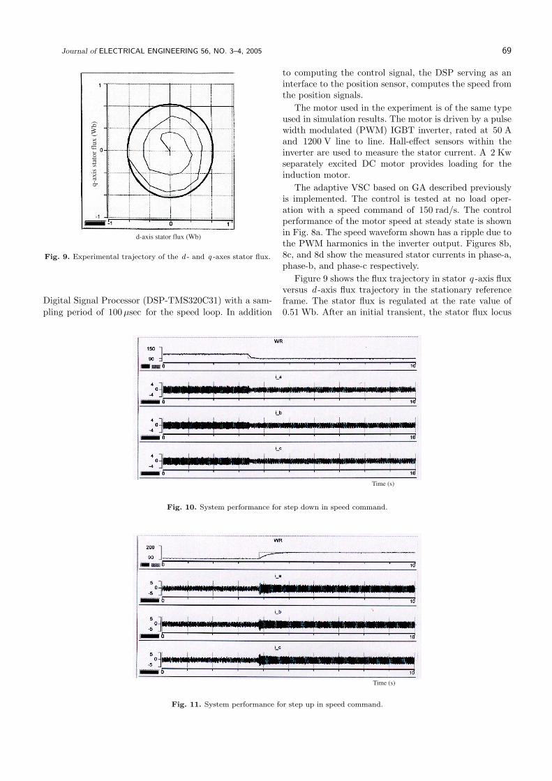
Fig. 9. Experimental trajectory of the d - and q -axes stator flux.
Digital Signal Processor (DSP-TMS320C31) with a sam-
pling period of 100µsec for the speed loop. In addition
to computing the control signal, the DSP serving as aninterface to the position sensor, computes the speed fromthe position signals.
The motor used in the experiment is of the same typeused in simulation results. The motor is driven by a pulsewidth modulated (PWM) IGBT inverter, rated at 50 Aand 1200 V line to line. Hall-effect sensors within theinverter are used to measure the stator current. A 2 Kwseparately excited DC motor provides loading for theinduction motor.
The adaptive VSC based on GA described previouslyis implemented. The control is tested at no load oper-ation with a speed command of 150 rad/s. The controlperformance of the motor speed at steady state is shownin Fig. 8a. The speed waveform shown has a ripple due tothe PWM harmonics in the inverter output. Figures 8b,8c, and 8d show the measured stator currents in phase-a,phase-b, and phase-c respectively.
Figure 9 shows the flux trajectory in stator q -axis fluxversus d -axis flux trajectory in the stationary referenceframe. The stator flux is regulated at the rate value of0.51 Wb. After an initial transient, the stator flux locus
Time (s)
Fig. 10. System performance for step down in speed command.
Time (s)
Fig. 11. System performance for step up in speed command.

70 E. E. El-kholy: HIGH PERFORMANCE INDUCTION MOTOR DRIVE BASED ON ADAPTIVE VARIABLE STRUCTURE CONTROL . . .
quickly becomes a circle. This means that the stator fluxresponse is kept nearly constant. Maintaining the statorflux constant will give the maximum torque sensitivitywith stator current, which is similar to that of a DCmachine.
The response of the control system due to a stepchange in speed command is shown in Fig. 10. The speedcommand is changed from 150 rad/s to 100 rad/s. It canbe seen from Fig. 10 that the motor speed is deceleratedsmoothly to follow its reference value. Figure 11, showthe motor response for step up in speed command, whichchange from 100 rad/s to 150 rad/s.
6 CONCLUSION
The major contribution of the present paper is thesuccessful implementation of a GA and applying it toimprove the control performance of an adaptive VSC forinduction motor control technique. The GA is designed toupdate the adaptation gain of the adaptive variable struc-ture controller to enhance the control performance of themotor drive system. The design, simulation, and imple-mentation of induction motor speed control system usingadaptive VSC based on GA have been presented. Simula-tion and experiment results are presented to demonstratethe potential of the proposed scheme. It has been shownthat the proposed scheme has several advantages such as,small steady state error, fast response and small overshootwith disturbance.
References
[1] ZHANG, J.—BARTON, T. H. : A Fast Variable Structure Cur-
rent Controller for an Induction Machine Drive, IEEE Transac-
tions on Industry Applications . 26 No. 3 (1990).
[2] FAA-JENG LIN—RONG-JONG WAI—HSIN-JANG SHIEH :
Robust Control of Induction Motor Drive With Rotor Time
Constant Adaptation, Electric Power Systems Research 47 No.
1 (1998), 1–9.
[3] HO, E. Y. Y.—SEN, P. C. : A Microprocessor-Based Induc-
tion Motor Drive System Using Variable Structure Strategy
with Decoupling, IEEE Transactions on Industrial Electronics
37 (1990), 227-235.
[4] HO, E. Y. Y.—SEN, P. C. : Control Dynamics of Speed Drive
System Using Sliding Mode Controllers with Integral Compen-
sation, IEEE Transactions on Industrial Application 27 (1991),
883–892.
[5] NANDAM, P. K.—SEN, P. C. : A Comparative Study of Luen-
berger Observer And Adaptive Observer-Based Variable Struc-
ture Speed Control System Using Self-Controlled Synchronous
Motor, IEEE Transactions on Industrial Electronics 37 (1990),
127–132.
[6] UTKIN, V. I. : Sliding Mode Control Design Principles and
Applications to Electric Drives, IEEE Transactions on Industrial
Electronics 40 (1993), 23–36.
[7] RAVITHARAN, G.—VILATHGAMUWA, D. M.—DUGGAL,
B. R. : Fuzzy Variable Structure Control of Induction Motors
with Sag Ride-Through Capability, 4th IEEE Power Electronics
and Drives Systems, Vol. 1, pp. 235–240, 22–25 Oct. 2001.
[8] ZHANG, J.—BARTON, T. H. : Optimal Sliding Mode Control
of Asynchronous Machine Speed with State Feedback, in Conf.
Rec. IEEE IAS Annual Meeting, pp. 328–336, 1988.
[9] LASCU, C.—BOLDEA, I.—BLAABJERG, F. : Direct Torque
Control of Sensorless Induction Motor Drives: a Sliding-Mode
Approach, IEEE Transactions on Industry Applications 40 No.
2 (2004), 582–590.
[10] SOTO, R.—YEUN, K. S. : Sliding-Mode Control of an Induc-
tion Motor without Flux Measurement, IEEE Transactions on
Industry Applications 31 No. 4 (1995), 744–751.
[11] KUKOLJ, D.—KULIC, F.—LEVI, E. : Design of the Speed
Controller for Sensorless Electric Drives Based on AI Tech-
niques: a Comparative Study, Artificial Intelligence in Engineer-
ing 14 No. 2 (2000), 165–174.
[12] GHAZY, M. A.—El-ZAMLY, M. N.—IBRAHIM, E. S. : Prac-
tical Variable Structure Approach for the Speed Control of DC
Motor, Second Middle East Power System Conference, MEP-
CON’92, Egypt, pp. 295–299, 1992.
[13] CHANG, F. J.—LIAO, H. J.—CHANG, S. : Position Control
of dc Motors via Variable Structure Systems Control: a Chat-
tering Alleviation Approach, IEEE Transactions on Industrial
Electronics 37 No. 6 (1990).
[14] El-SHARKAWI, M. A. : Development and Implementation
of High Performance Variable Structure Tracking Control for
Brushless Motors, IEEE Transactions on Energy Conversion 6
No. 1 (1991).
[15] El-SADEK, M. Z.—El-SAADY, G.—ABO-El-SAUD, M. : A
Variable Structure Adaptive Neural Network Static VAR Con-
troller, Electric Power Systems Research 45 (1998), 109-117.
[16] CHERN, T. L.—CHANG, J.—CHANG, G. K. : DSP-Based In-
tegral Variable Structure Model Following Control for Brushless
DC Motor Drivers, IEEE Transactions on Power Electronics, 12
No. 1 (1997), 53-63.
[17] LIN, F. J.—CHOU, W. D. : An Induction Motor Servo Drive
Using Sliding-Mode Controller with Genetic Algorithm, Electric
Power Systems Research 64 (2003), 93–108.
Received 2 May 2004
Elwy E. El-kholy was born in Menoufiya, Egypt in 1963.
He received his BSc, and MSc degree in Electrical Engineering
from Faculty of Engineering, Menoufiya University in 1986,
and 1992 respectively. From January 1993 to January 1996
he was PhD student at the INPL, Nancy University, France,
under an academic channel exchange program. He received
his PhD degree in 1996. He was a visiting research fellow to
INPL, Nancy University, France during summer 1997. He was
a visiting professor to Electrical Machines and Drives Dept.,
Wuppertal University, Germany during August 2001 to Jan-
uary 2002. He joined the Department of Electrical Engineer-
ing, Faculty of Engineering, Menoufiya University as a demon-
strator in 1986. Then, he became an assistant lecturer in 1992
and was appointed as an assistant professor in 1996. In July
2002, he was appointed as an associating professor. His main
professional interests include ac and dc drives, direct torque
and field oriented control techniques, DSP control and Power
Electronics. He has published several technical papers in these
areas. He is now on a sabbatical leave to Aljouf Technical Col-
lege, Saudi Arabia.