high performance organic sodium-ion hybrid capacitors
TRANSCRIPT

Green Chemistry
PAPER
Cite this: Green Chem., 2018, 20,4920
Received 26th June 2018,Accepted 17th September 2018
DOI: 10.1039/c8gc01987h
rsc.li/greenchem
High performance organic sodium-ion hybridcapacitors based on nano-structured disodiumrhodizonate rivaling inorganic hybrid capacitors†
Ranjith Thangavel, a Rubha Ponraj,b Aravindaraj G. Kannan, b
Karthikeyan Kaliyappan,c Dong Won Kim, b Zhongwei Chen c andYun-Sung Lee *a
Sodium hybrid capacitors (NHCs) have tremendous potential to meet the simultaneous high energy–high
power requirement of next-generation storage applications. But NHCs still face some obstacles due to
poor sodium ion kinetics, low power, and poor cyclability while working with several inorganic sodium
ion hosts. Additionally, developing high-performance NHCs that are sustainable and versatile is more
crucial from the perspective of energy storage devices. Here, we report a conceptually new and high per-
formance organic sodium hybrid capacitor (ONHC) system, developed by substituting a conventional
toxic-metal-containing inorganic battery electrode of an NHC with a nano-structured, metal free, and
renewable organic molecule – disodium rhodizonate – to host sodium ions. The sustainability of the
ONHC is greatly enhanced by the simultaneous utilization of high surface area cardamom shell (as
biomass)-derived porous carbon as a high-power capacitor electrode. The new system exhibits an out-
standing performance, delivering a high energy density of ∼87 W h kg−1 along with a high specific power
of 10 kW kg−1 (based on the mass in both electrodes), outperforming inorganic sodium hosts. High dura-
bility over 10 000 cycles (∼85% retention) with an ultra-low energy loss of ∼0.15% per 100 cycles is also
demonstrated, indicating its emergence as a rival to conventional metal containing lithium and sodium
hybrid capacitors. The current study provides new opportunities for developing greener and sustainable
devices beyond conventional systems for next-generation storage applications.
1. Introduction
Electrical energy storage (EES) devices delivering a simul-taneous high energy–high power characteristic have generatedtremendous attention for utilization in future electric vehiclesand power-grid applications. Though batteries have a highenergy density, their sluggish kinetics leads to inferior powerbehavior, impeding the output performance. The developmentof hybrid capacitor (HC) systems established a trade-offrelationship between the merits of batteries and capacitors todeliver an enhanced energy output at a higher power and witha longer operation life. The simultaneous intercalation/dein-
tercalation processes in a battery type electrode together withthe adsorption/desorption process in a capacitor type electrodeprovides a high output energy under high-power conditions.Lithium hybrid capacitors (LHCs) have become commerciallysuccessful and are expected to be used in electric vehicles andhybrid electric vehicles in the future.
However, the limited lithium resources cannot fulfill thehigh industrial demand at a low price. This has diverted theresearch interest beyond lithium-based energy storage systems,and the quest for a competitive system is still under investi-gation. Sodium ion-based energy storage systems have evolvedas capable alternatives to lithium-based systems owing to thewide availability of sodium and the similarity in the workingchemistry of the two devices.1,2 However, high power realiz-ation is more difficult in a battery configuration because of thelarge-sized sodium ion. Consequently, the research trend hasshifted toward sodium-ion hybrid capacitors.3,4 Sodium hybridcapacitors (NHCs) are a new class of devices with a strongpotential to achieve high energy and high power with a longerstability due to the simultaneous occurrence of battery typeintercalation/de-intercalation and capacitor type adsorption/
†Electronic supplementary information (ESI) available. See DOI: 10.1039/c8gc01987h
aFaculty of Applied Chemical Engineering, Chonnam National University, Gwang-
ju 500-757, Korea. E-mail: [email protected] of Chemical Engineering, Hanyang University, Seungdong-gu,
Seoul 133-791, KoreacDepartment of Chemical Engineering, University of Waterloo, Waterloo,
Ontario N2L 3G1, Canada
4920 | Green Chem., 2018, 20, 4920–4931 This journal is © The Royal Society of Chemistry 2018
Publ
ishe
d on
19
Sept
embe
r 20
18. D
ownl
oade
d by
Han
yang
Uni
vers
ity o
n 11
/13/
2018
10:
48:3
6 A
M.
View Article OnlineView Journal | View Issue

desorption reactions. Thus, NHCs have the potential to beapplied in next-generation devices.5–7
Research on battery type electrodes has considerablyincreased, including studies on Na3V2(PO4)3, hard carbon,MXenes, V2O5, Nb2O5, and NaTi3O7, to improve the perform-ance of NHCs.8–14 Very recently, high-performance NHCsystems have been demonstrated to outperform their lithiumanalogues both in terms of energy and power densities,proving NHCs to be suitable alternatives to LHCs.15–19
The current urgent concern is to develop a green and versa-tile energy storage system without sacrificing the output per-formance.20,21 However, highly toxic inorganic compounds areinevitable in EES devices, and the depleting inorganicresources could result in supply restrictions, increasing theglobal alarm regarding the sustainability, greenness, and costof EES. Furthermore, overcoming the harmful and hazardousextraction processes for toxic inorganic complexes is essentialto achieve a sustainable environment.22,23 Intensive researchhas established metal-free, green, and eco-friendly organiccompounds as next-generation clean energy storage materials,and they have been investigated for usage in organic lithiumion batteries and sodium ion batteries (SIBs).24,25 To date,such green organic compounds have not been used in highenergy–high power hybrid capacitor devices. The utilization oforganic molecules in NHCs has resulted in the emergence of anew class of inorganic compound-free, green energy storagesystems, namely, organic sodium hybrid capacitors (ONHCs),which could be promising for delivering high energy at a highpower.
Various organic compounds with an active redox center tohost Na+ ions were studied for organic SIBs.26–28 In the searchfor a potential candidate, disodium rhodizonate (DSRH) couldbe an appropriate choice to act as a green battery electrode inONHCs, hosting sodium ions. Its numerous advantages,including a wide structural flexibility, tailored moleculardesign, easy tuning of the redox potential for multi-electrontransfer reactions, light weight, high capacity, and abundantavailability in nature, make this organic compound morebenign for energy storage applications.29–31 Additionally,DSRH, belonging to the keto–carbonyl group, having soft andflexible organic compounds, can be incorporated into large-sized sodium ions with a very low volume expansion and isfavorable for delivering a high-current performance.32
However, the practical capacity, rate performance andcyclability of DSRH need a lot of improvement when used infast working capacitor devices. It is well known that thesodium ion storage kinetics greatly depends on the mor-phology and size effects of the host material. In the presentstudy, the sodium ion storage kinetics was improved by utiliz-ing nano-structured DSRH synthesized by a facile antisolventtechnique. In comparison with bulk commercial DSRH (bulk-DSRH) and high energy ball milled DSRH with reduced par-ticle size (milled-DSRH), nano-structured DSRH (nano-DSRH)showed improved capacity, rate performance and stability.
To completely realize the eco-friendliness of a new ONHC,considerable attention must be paid to capacitor type adsorp-
tion electrodes. Capacitor type electrodes are generally com-posed of porous carbon, and their ion storage mechanisminvolves a simple double-layer formation at the electrode–elec-trolyte interface.33 To date, commercially available activatedcarbon derived from coal and pitch has been used in a batterytype electrode.34 Utilization of materials from such exhaustibleand environmentally hazardous resources could question thecomplete sustainability of an ONHC device.
As an alternative, biomass-derived porous carbon could bean excellent candidate for maintaining the eco-friendliness ofONHCs. Although biomass-derived porous carbon has beenwidely used in electrical double-layer capacitors and LHCs,there are not many reports on its application in NHCs, and itdemands an extensive investigation. Biomass-derived porouscarbon has the advantages of a high surface area, large porevolume, and ease of tailoring its morphology and surface func-tionalities, which could be beneficial for the fast accommo-dation of the large-sized solvated ions from the organic electro-lyte.35,36 The wide availability of waste biomass is highly advan-tageous for achieving a large-scale manufacturing process andfacilitating the recycling of waste. A highly porous in situ nitro-gen-doped cardamom shell-derived porous carbon (CDC) isknown to have been utilized as a high-power capacitor elec-trode in ONHCs.
Herein, we report a conceptually new class of energy storagedevices, namely, an ONHC fabricated by substituting a tra-ditional toxic transition metal-containing Na+ ion insertioncompound with metal-free, green, and redox active commercialDSRH as an organic Na+ ion host. Furthermore, to make thesystem still cleaner and greener, a highly porous biomass-derived carbon, i.e., CDC, is utilized as a high-power adsorp-tion electrode. The new ONHC device operates by establishinga trade-off relationship between the advantages of a batteryand a capacitor, and it could emerge as a cleaner, greener, anda more sustainable alternative to conventional energy storagedevices.
2. Experimental
Commercial DSRH was obtained and used directly withoutfurther processing for bulk-DSRH analysis. Commercial DSRHwas milled for 1 h in a Pulverisette-6 planetary ball mill. Fornano-DSRH, bulk-DSRH was dissolved in water (5 mg ml−1)and mixed with ethanol in a ratio of 1 : 10 by volume. After10 min sonication, DSRH precipitates were collected byvacuum filtration and then dried at 60 °C for 8 h undervacuum. Cardamom shells purchased from the local foodmarket were used in this study. The seeds inside the carda-mom shells were first removed, and the shells were thoroughlywashed with water to remove any impurities and then dried at120 °C for 48 h. The shells were then carbonized in air at300 °C for 2 h and chemically activated with KOH at 750 °C for1.5 h under an argon atmosphere. The weight ratio of the car-bonized precursor to the pore-forming agent (KOH) was fixedat 1 : 5. The resultant products were washed with 0.1 M HCl,
Green Chemistry Paper
This journal is © The Royal Society of Chemistry 2018 Green Chem., 2018, 20, 4920–4931 | 4921
Publ
ishe
d on
19
Sept
embe
r 20
18. D
ownl
oade
d by
Han
yang
Uni
vers
ity o
n 11
/13/
2018
10:
48:3
6 A
M.
View Article Online

and then washed several times with water and ethanol forneutralization. The products were next vacuum-dried at 120 °Cfor 24 h.
3. Characterization3.1 Physical characterization
XRD patterns of all the samples were recorded using a RigakuRint 1000 (Japan) diffractometer using Cu Kα as the radiationsource. The morphological features of the samples were deter-mined using field emission SEM (FE-SEM) (S4700, Hitachi,Japan) and high-resolution TEM (HR-TEM) (Tecnai F20,Philips, Holland). Fourier transform infrared spectroscopy(FT-IR) was performed using a Nicolet FT-IR 200 from ThermoScientific. Nuclear magnetic resonance (NMR) spectroscopywas conducted on a Bruker Avance 600 MHz spectrometer. TheRaman spectra were recorded using a Raman dispersivespectrometer (LabRam HR 800 Horiba, Japan). Nitrogenadsorption and desorption isotherm measurements were per-formed using a Micromeritics ASAP 2010 analyzer. XPS wasperformed using a Multilab instrument (monochromatic AlKα, radiation hγ = 1486.6 eV).
3.2 Electrochemical characterization
DSRH electrodes were prepared using Ketjen black and PVDFas the conductive carbon and binder, respectively. The ratio ofthe active material to the conductive carbon and binder wasmaintained at 75 : 15 : 10. The produced slurry was pasted overa stainless-steel foil and dried at 120 °C for 12 h before use.The CDC and commercial activated carbon (CAC) cathode wereprepared using Ketjen black and teflonized-acetylene black(TAB) as the conductive carbon and binder, respectively. Theratio of the active material to the conductive carbon andbinder was maintained at 80 : 10 : 10. The slurry was thenrolled over a stainless-steel mesh and dried at 160 °C for 4 hbefore use. The textural properties of CAC were given in ourprevious publication.36 All the electrochemical measurementswere performed in a standard CR2032 coin-cell assembledinside an argon-filled glove box. The half-cell performance ofDSRH and CDC was tested against the Na metal, separated bya porous polypropylene (Celgard 3401, USA) separator. For theHC testing, the mass ratio of DSRH to CDC was kept at 1 : 1.5and a mass loading of 1.8–2.4 mg cm−2 was maintained. Theelectrolyte used was NaClO4 in ethylene carbonate (EC)/dimethyl carbonate (DMC) (1 : 1 vol/vol). CV and EIS studieswere performed in a Bio-Logic (SP-150, France) electrochemicalworkstation. The galvanostatic charge/discharge studies wereperformed between 0 V and 3 V at different current densitiesusing a Won-A-Tech WBCS 3000 (Korea) cycle tester. Theenergy density and power density were calculated using theformulae E = (P × t ) W h kg−1 and P = (IV/2) W kg−1, respect-ively, where I is the current normalized to the active mass inboth the electrodes (A g−1), V is the working potential of thesystem (V), and t is the discharge time (s).
4. Results and discussion
The chemical structure of DSRH in Fig. 1a is a keto–carbonylorganic compound, composed of a six-membered carbon ringthat includes a carbon–carbon double bond and four carbonylgroups.37,38 The crystal structure of DSRH in Fig. 1b constitu-tes a layered structure with alternating hexagonally packedsodium ions (Na+) and rhodizonate (C6O6
2−) layers, which ishighly beneficial for easy and fast sodium insertion. Theelectron-rich keto–carbonyl groups are highly redox activesites for hosting Na+ ions. Owing to its high lattice energy,DSRH can efficiently retain the Na–O ionic bond and exhibitexcellent stability in organic electrolytes.37 These favorableattributes of DSRH are highly analogous to the present in-organic sodium ion hosts, and DSRH could emerge as a suit-able high-energy battery electrode for ONHCs. The X-ray diffr-action (XRD) patterns of bulk-DSRH and nano-DSRH in Fig. 1cremain the same with a crystalline nature and exhibit an ortho-rhombic structure associated with the Fddd space group.However, milled-DSRH has a loss of crystallinity after themilling process where sharp peaks merge to form a broaderone.
The scanning electron microscopy (SEM) images of variousDSRH types are shown in Fig. 1d–f. Commercial bulk-DSRHshows the presence of microcrystals (∼50 μm) with an octa-hedron-like morphology. The milled-DSRH shows a reducedparticle size (∼2 μm) even after 1 h of high energy ball milling.However, the nano-DSRH synthesized by the anti-solvent pre-cipitation strategy shows the presence of agglomerated nano-sized particles (150–200 nm). The TEM images of the DSRHstructures (Fig. 1g–i) further confirm the structural modifi-cation of bulk-DSRH after milling and the anti-solvent precipi-tation process. The selected area diffraction (SAED) patterngiven in the inset of the TEM images shows the presence ofdiffuse rings with bright spots, indicating the polycrystallinenature of DSRH. The polycrystalline nature is retained evenwith milled-DSRH and nano-DSRH. The driving force for theformation of nano-DSRH is the rapid supersaturation of DSRHin an ethanol anti-solvent followed by crystallization in awater/ethanol mixture. The nano-morphology can lead to a fastcapacitive reaction, resulting from the rapid ionic diffusioncompared with the micron-sized DSRHs. Additionally, thehighly conjugated organic structure with a high ionic and elec-tronic conductivity can easily favor pseudocapacitive ionstorage at high currents.32 The chemical structure of all DSRHsamples are verified by FT-IR and NMR spectroscopy and theresults are given in Fig. S1.† The FT-IR spectra of milled-DSRHand nano-DSRH in Fig. S1a† exhibit a broad band between∼1400 and 1600 cm−1 corresponding to CvC and CvO. Thespectra are similar to the FT-IR spectrum of bulk-DSRH(commercial sample), indicating that the functional groups areunchanged. In addition, 13C-NMR of bulk-DSRH, milled-DSRHand nano-DSRH also reveals that the structures remain intact.Irrespective of the different morphological characteristics,bulk-DSRH, milled-DSRH, and nano-DSRH show similarchemical structures.
Paper Green Chemistry
4922 | Green Chem., 2018, 20, 4920–4931 This journal is © The Royal Society of Chemistry 2018
Publ
ishe
d on
19
Sept
embe
r 20
18. D
ownl
oade
d by
Han
yang
Uni
vers
ity o
n 11
/13/
2018
10:
48:3
6 A
M.
View Article Online

The SEM images in Fig. S2a† show that the CDC particlesare within a few micrometers, over which numerous pores arerandomly distributed. Transmission electron microscopy(TEM) images of the CDC (Fig. S2b and c†) again confirm thatthe randomly distributed nanosized pores are less than 5 nmand are arranged in a hierarchical manner. The N2-adsorption/desorption isotherm of the CDC (Fig. S3†) exhibits a combi-nation of type I/IV isotherms with a high BET surface area of∼2200 m2 g−1 and a large pore volume of 1.51 cm3 g−1.39 Itreveals a narrow pore distribution of small mesopores andmicropores, among which ∼26% are mesopores and 74% aremicropores. The XRD patterns of the CDC shown in Fig. S4a†depict a highly amorphous nature with broad graphitic peaksat approximately 23° and 44°, indicating a highly disorderedand turbostratic nature of the CDC. The d-spacing (002 plane)of the CDC is calculated to be 0.378 nm, which is larger thanthat of graphite (0.355 nm), emphasizing the broadening ofthe graphitic planes after KOH activation.33 The Raman spec-trum of the CDC (Fig. S4b†) exhibits two characteristic bands:(i) a G band at ∼1594 cm−1 related to the in-plane vibrationalgraphitic domains and (ii) a D band at ∼1349 cm−1 related tothe defect and disorder bands in the CDC. The ID/IG ratio iscalculated to be ∼1.03.
The surface nature of the CDC was examined by X-rayphotoelectron spectroscopy (XPS), and the results are displayedin Fig. S5a.† The complete XPS survey spectrum of the CDCshows the presence of carbon and oxygen along with nitrogen.The numerous nitrogen containing minerals and acids in the
cardamom shells could be the source of the nitrogen hetero-atoms that get incorporated into the carbon framework duringcarbonization and activation. The other metal impurities inthe CDC are under the detection limit of XPS as it is removedduring the acid washing step. The deconvoluted C 1s and N 1sspectra of the CDC are illustrated in Fig. S5b and c,† respect-ively. The C 1s spectrum displays a dominating central peak at∼284.6 eV, corresponding to C–C bond sp2-hybridized carbon.The short peaks at ∼286 eV (CvO) and ∼288.5 eV (O–CvO)indicate the presence of oxygen containing functionalgroups.40 The deconvoluted N 1s spectrum shows peaks at∼398.3 eV, ∼399.8 eV, and ∼401.1 eV, indicating the contri-bution from pyridine, pyrrole, and a quaternary type nitrogen.These contribute toward the enhancement of the electronicconductivity of the carbon framework.41
The hybrid porous architecture along with the nitrogenheteroatoms in the CDC could render enhanced kinetics fordouble-layer adsorption. The mesopore channels ensure ashort ion-flow path to deeper micropores under high-currentconditions, thereby involving the micropores in an active ionadsorption process. By providing a high surface area alongwith large mesopores, biomass CDC could be a promisinghigh-power capacitor electrode for ONHCs.42
4.1 Half-cell performance
The charge–discharge (CD) curves of all DSRH at 0.1 A g−1 areshown in Fig. S6.† The series of consecutive symmetrical pla-teaus in the CD profile indicate a sequential sodium ion
Fig. 1 (a) Chemical structure of DSRH, (b) the crystal structure of DSRH, (c) XRD patterns of DSRH, SEM images of (d) bulk-DSRH, (e) milled-DSRH,and (f ) nano-DSRH, and TEM images and SAED patterns of (g) bulk-DSRH, (h) milled-DSRH, and (i) nano-DSRH.
Green Chemistry Paper
This journal is © The Royal Society of Chemistry 2018 Green Chem., 2018, 20, 4920–4931 | 4923
Publ
ishe
d on
19
Sept
embe
r 20
18. D
ownl
oade
d by
Han
yang
Uni
vers
ity o
n 11
/13/
2018
10:
48:3
6 A
M.
View Article Online
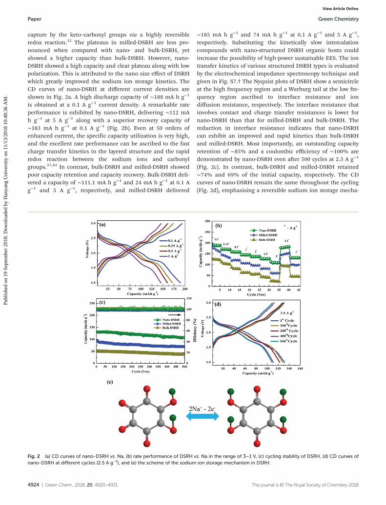
capture by the keto–carbonyl groups via a highly reversibleredox reaction.32 The plateaus in milled-DSRH are less pro-nounced when compared with nano- and bulk-DSRH, yetshowed a higher capacity than bulk-DSRH. However, nano-DSRH showed a high capacity and clear plateau along with lowpolarization. This is attributed to the nano size effect of DSRHwhich greatly improved the sodium ion storage kinetics. TheCD curves of nano-DSRH at different current densities areshown in Fig. 2a. A high discharge capacity of ∼188 mA h g−1
is obtained at a 0.1 A g−1 current density. A remarkable rateperformance is exhibited by nano-DSRH, delivering ∼112 mAh g−1 at 5 A g−1 along with a superior recovery capacity of∼183 mA h g−1 at 0.1 A g−1 (Fig. 2b). Even at 50 orders ofenhanced current, the specific capacity utilization is very high,and the excellent rate performance can be ascribed to the fastcharge transfer kinetics in the layered structure and the rapidredox reaction between the sodium ions and carbonylgroups.37,43 In contrast, bulk-DSRH and milled-DSRH showedpoor capacity retention and capacity recovery. Bulk-DSRH deli-vered a capacity of ∼111.1 mA h g−1 and 24 mA h g−1 at 0.1 Ag−1 and 5 A g−1, respectively, and milled-DSRH delivered
∼185 mA h g−1 and 74 mA h g−1 at 0.1 A g−1 and 5 A g−1,respectively. Substituting the kinetically slow intercalationcompounds with nano-structured DSRH organic hosts couldincrease the possibility of high-power sustainable EES. The iontransfer kinetics of various structured DSRH types is evaluatedby the electrochemical impedance spectroscopy technique andgiven in Fig. S7.† The Nyquist plots of DSRH show a semicircleat the high frequency region and a Warburg tail at the low fre-quency region ascribed to interface resistance and iondiffusion resistance, respectively. The interface resistance thatinvolves contact and charge transfer resistances is lower fornano-DSRH than that for milled-DSRH and bulk-DSRH. Thereduction in interface resistance indicates that nano-DSRHcan exhibit an improved and rapid kinetics than bulk-DSRHand milled-DSRH. Most importantly, an outstanding capacityretention of ∼85% and a coulombic efficiency of ∼100% aredemonstrated by nano-DSRH even after 500 cycles at 2.5 A g−1
(Fig. 2c). In contrast, bulk-DSRH and milled-DSRH retained∼74% and 69% of the initial capacity, respectively. The CDcurves of nano-DSRH remain the same throughout the cycling(Fig. 2d), emphasising a reversible sodium ion storage mecha-
Fig. 2 (a) CD curves of nano-DSRH vs. Na, (b) rate performance of DSRH vs. Na in the range of 3–1 V, (c) cycling stability of DSRH, (d) CD curves ofnano-DSRH at different cycles (2.5 A g−1), and (e) the scheme of the sodium ion storage mechanism in DSRH.
Paper Green Chemistry
4924 | Green Chem., 2018, 20, 4920–4931 This journal is © The Royal Society of Chemistry 2018
Publ
ishe
d on
19
Sept
embe
r 20
18. D
ownl
oade
d by
Han
yang
Uni
vers
ity o
n 11
/13/
2018
10:
48:3
6 A
M.
View Article Online

nism. The sodium ion storage mechanism in DSRH is shownin Fig. 2e.
To elucidate the fast sodium ion storage behavior of nano-DSRH, cyclic voltammetry (CV) was performed at differentscan rates. The corresponding CV curves in Fig. 3a display aseries of four consecutive redox peaks in both the cathodicand anodic scans. During the cathodic scan, the peaks are cen-tered at ∼2.46 V, 2.27 V, 2.04 V, and 1.72 V, whereas during thesubsequent anodic scan, the peaks are centered at ∼1.87 V,2.11 V, 2.36 V, and 2.62 V. This indicates a highly reversibleand sequential sodium insertion in nano-DSRH via a four-electron redox process.32,44 Even with the increase in the scanrate, nano-DSRH preserves the shape of the CV curves, and theredox peaks are clearly visible. The highly symmetrical andidentical redox peaks even at higher scan rates suggest a facilesodium insertion even under high-power conditions.
The current (i) vs. scan rate (ν) relationship from theequation i = aνb (a and b are adjustable parameters) depictsthe nature of sodium storage in DSRH. A b-value closer to“0.5” implies diffusion-controlled intercalation storage,whereas a b-value closer to “1” implies that the dominantcapacity contribution is from surface-limited pseudocapacitive
surface storage.45 Fig. 3b shows the plot of log(i) versus log(ν)derived from the maximum output current in the anodic andcathodic scans at different scan rates. The “b-value” obtainedfrom the slope of the linear fit is approximately 1, indicatingthat the major current contribution is from surface-inducedpseudocapacitive sodium storage.46 Such a fast pseudo-capacitive sodium is favorable for achieving a high energy evenunder high-current conditions in the ONHC. In contrast, slug-gish diffusion-limited sodium storage in a battery type elec-trode of an ONHC will cause a high energy loss at high power.However, with fast surface-limited ion storage, the energy lossat high power could be easily curtailed.
To understand the phase change in nano-DSRH, the crystalstructure of DSRH is evaluated after cycling using the XRDtechnique (Fig. S8†). Cycled nano-DSRH loses almost all of itscrystallinity and an evolution of completely new peaks whichdid not match with its original phase is noted. This is attributedto the formation of the most stable and new γ-phase from theα-phase following the first sodiation process. The newly formedγ-phase of DSRH also has a layered structure where C6O6 layerslie directly over each other and this new phase takes a differentpath for sodium ion storage.47 This is confirmed by the changein the discharge curve patterns of DSRH after the first sodiationprocess (Fig. S9a†). However, the CD curve pattern appears wellmaintained throughout from the second sodiation process.Additionally, this phase change and the new sodiation pathfrom the second cycle are also verified by CV studies (Fig. S9b†),where the 1st cathodic scan and the 2nd cathodic scan showdifferent storage patterns, but the patterns are well maintainedafter the second scan, and this phenomenon is correlated withthe CD curves obtained. However, this phase change does notaffect the sodium ion storage process as high capacity and highrate performance are attained along with high stability.20
FE-SEM images are recorded for nano-DSRH after 1st discharge(Fig. 4a) and consecutive charge (Fig. 4b), and the morphologyof DSRH does not show any significant changes. Even after100 cycles, the morphology of nano-DSRH is well maintained(Fig. 4c), indicating its structurally stable nature.
The sodium ion kinetics in nano-DSRH is further investi-gated using the electrochemical impedance spectra (EIS) andthe results are presented in Fig. 4d and e. The Nyquist plots offresh nano-DSRH cells show a large semi-circle at high fre-quency attributed to charge transfer resistance, followed by aWarburg impedance tail at low frequency, indicating thediffusion of sodium ions into the electrode. After the first dis-charge process (sodiation to 1 V vs. Na), the Nyquist plot dis-plays two semi-circles confirming the sodiation of nano-DSRH.On subsequent charge (desodiation to 3 V vs. Na), the semi-circle in the mid-frequency range disappeared and instead asingle semicircle with a lower charge transfer than the freshcell, indicating better electron and sodium ion kinetics, asshown in Fig. 4d, appeared. In addition, even after cycling, theincrease in charge transfer resistance (Fig. 4e) is very negligibleindicating a fast and stable charge–discharge process.
The outstanding high current and the cycling behavior oforganic compounds are highly attractive when compared with
Fig. 3 (a) Cyclic voltammetry (CV) curves of nano-DSRH vs. Na and (b)current vs. scan rate relationship obtained from the CV curves.
Green Chemistry Paper
This journal is © The Royal Society of Chemistry 2018 Green Chem., 2018, 20, 4920–4931 | 4925
Publ
ishe
d on
19
Sept
embe
r 20
18. D
ownl
oade
d by
Han
yang
Uni
vers
ity o
n 11
/13/
2018
10:
48:3
6 A
M.
View Article Online

those of the inorganic insertion compounds. The fast andreversible sodium intake and release via a pseudocapacitivereaction minimizes the energy loss and enables a robust stabi-lity, ensuring the development of a new class of high energystorage devices.
The CD curves of the CDC are presented in Fig. 5a toexamine their adsorption behavior. A linear and non-deviatingCD curve between 3 and 4.5 V vs. Na corresponds to a puresurface adsorption reaction over the CDC pores.48 The CDCdelivers an impressive discharge capacity of ∼70 mA h g−1,equivalent to ∼152 F g−1 at 0.25 A g−1. Significantly, onincreasing the current density to 8 A g−1, the CDC maintains aremarkable capacity of ∼24 mA h g−1 (55 F g−1) (inset, Fig. 5a).Notably, the CDC demonstrates excellent stability, retaining∼90% of the initial capacitance even after 3000 cycles (Fig. 5b).Compared with previously studied adsorption electrodes forHCs, the CDC exhibits better rate performance and stability,suggesting the use of bio-derived porous carbon as a high-power and long-life adsorption electrode for ONHCs.6 Theobserved superior properties of the CDC are attributed to itshighly porous nature along with the micro–mesopore architec-ture, which is highly favorable for ion accumulation. The ionscontinuously flow through the mesopore channels to deepersub-micropores, are stored in the ionic reservoirs, and activelyparticipate in the adsorption reaction. The large pore volumeof the CDC could store a large volume of the electrolyte for alonger time and thereby ensure the longevity of the adsorptionreaction.21,49–51
4.2 Organic sodium hybrid capacitor
Considering the remarkable performance of nano-DSRH com-pared with bulk- and milled-DSRH, nano-DSRH is furtherstudied for use in hybrid capacitor applications in the 0–3 V
Fig. 4 SEM images of nano-DSRH (a) after 1st discharge, (b) after 1st charge, and (c) after 100 cycles, and (d) and (e) Nyquist plots of nano-DSRH atdifferent states.
Fig. 5 (a) Charge/discharge curves of CDC, Inset: rate performance,and (b) the cycling stability of CDC.
Paper Green Chemistry
4926 | Green Chem., 2018, 20, 4920–4931 This journal is © The Royal Society of Chemistry 2018
Publ
ishe
d on
19
Sept
embe
r 20
18. D
ownl
oade
d by
Han
yang
Uni
vers
ity o
n 11
/13/
2018
10:
48:3
6 A
M.
View Article Online
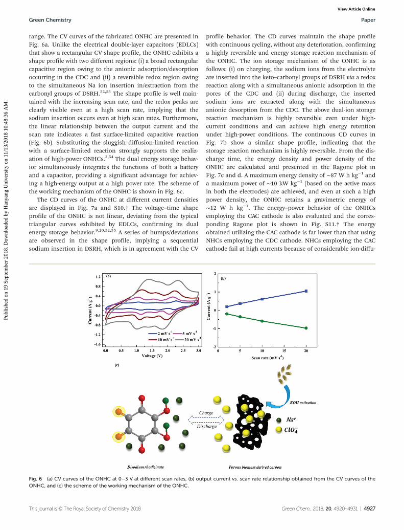
range. The CV curves of the fabricated ONHC are presented inFig. 6a. Unlike the electrical double-layer capacitors (EDLCs)that show a rectangular CV shape profile, the ONHC exhibits ashape profile with two different regions: (i) a broad rectangularcapacitive region owing to the anionic adsorption/desorptionoccurring in the CDC and (ii) a reversible redox region owingto the simultaneous Na ion insertion in/extraction from thecarbonyl groups of DSRH.52,53 The shape profile is well main-tained with the increasing scan rate, and the redox peaks areclearly visible even at a high scan rate, implying that thesodium insertion occurs even at high scan rates. Furthermore,the linear relationship between the output current and thescan rate indicates a fast surface-limited capacitive reaction(Fig. 6b). Substituting the sluggish diffusion-limited reactionwith a surface-limited reaction strongly supports the realiz-ation of high-power ONHCs.3,54 The dual energy storage behav-ior simultaneously integrates the functions of both a batteryand a capacitor, providing a significant advantage for achiev-ing a high-energy output at a high power rate. The scheme ofthe working mechanism of the ONHC is shown in Fig. 6c.
The CD curves of the ONHC at different current densitiesare displayed in Fig. 7a and S10.† The voltage–time shapeprofile of the ONHC is not linear, deviating from the typicaltriangular curves exhibited by EDLCs, confirming its dualenergy storage behavior.9,20,52,55 A series of humps/deviationsare observed in the shape profile, implying a sequentialsodium insertion in DSRH, which is in agreement with the CV
profile behavior. The CD curves maintain the shape profilewith continuous cycling, without any deterioration, confirminga highly reversible and energy storage reaction mechanism ofthe ONHC. The ion storage mechanism of the ONHC is asfollows: (i) on charging, the sodium ions from the electrolyteare inserted into the keto–carbonyl groups of DSRH via a redoxreaction along with a simultaneous anionic adsorption in thepores of the CDC and (ii) during discharge, the insertedsodium ions are extracted along with the simultaneousanionic desorption from the CDC. The above dual-ion storagereaction mechanism is highly reversible even under high-current conditions and can achieve high energy retentionunder high-power conditions. The continuous CD curves inFig. 7b show a similar shape profile, indicating that thestorage reaction mechanism is highly reversible. From the dis-charge time, the energy density and power density of theONHC are calculated and presented in the Ragone plot inFig. 7c and d. A maximum energy density of ∼87 W h kg−1 anda maximum power of ∼10 kW kg−1 (based on the active massin both the electrodes) are achieved, and even at such a highpower density, the ONHC retains a gravimetric energy of∼12 W h kg−1. The energy–power behavior of the ONHCsemploying the CAC cathode is also evaluated and the corres-ponding Ragone plot is shown in Fig. S11.† The energyobtained utilizing the CAC cathode is far lower than that usingNHCs employing the CDC cathode. NHCs employing the CACcathode fail at high currents because of considerable ion-diffu-
Fig. 6 (a) CV curves of the ONHC at 0–3 V at different scan rates, (b) output current vs. scan rate relationship obtained from the CV curves of theONHC, and (c) the scheme of the working mechanism of the ONHC.
Green Chemistry Paper
This journal is © The Royal Society of Chemistry 2018 Green Chem., 2018, 20, 4920–4931 | 4927
Publ
ishe
d on
19
Sept
embe
r 20
18. D
ownl
oade
d by
Han
yang
Uni
vers
ity o
n 11
/13/
2018
10:
48:3
6 A
M.
View Article Online

sional losses in microporous activated carbon. However, NHCsemploying CDC as the cathode performed well with highenergy retention due to the favorable textural and surface pro-perties of the green carbon. The ONHC energy densityobtained is much higher than the energy output of EDLCs,and its output specific power surpasses the power of batteries,covering a wide range, bridging the gap between the low-powerbatteries and low-energy supercapacitors. The electrochemicalperformance of the ONHC is highly competitive and it outper-forms the conventional LHCs and NHCs utilizing inorganicinsertion hosts.56,57 The Ragone plots in Fig. 7c and dcompare the output performance of the ONHC with otherHCs, and it clearly shows its higher performance than thewidely investigated lithium and sodium HCs utilizing variousion hosts such as Li4Ti5O12, TiO2, V2O5, Nb2O5, NiCo2O4 andNa3V2(PO4)3 and many more.58–63
Stability is the most significant parameter for HCs, and thelong-term performance of the ONHC was tested at specificcurrent density of 4 A g−1. The new ONHC exhibits high per-formance for 10 000 cycles with an energy loss of 0.15% per100 cycles with ∼100% coulombic efficiency (Fig. 7e). A slightincrease in the capacitance is noted initially, which could beattributed to the delayed electrolyte infiltration in the organicand porous carbon electrodes. This activates the innermostelectrode particles for electrochemical storage, and such aphenomenon has been observed previously for both organictype and carbon electrodes. An ultra-low energy loss of only4% is noted from the 2000th cycle. Table S1† compares theoutput performance of the ONHC with conventional HCs, andit provides evidence of the superiority of the new ONHC, show-casing that it could be a powerful and analogous alternative.
The Ragone plot in Fig. 8a confirms the high energy–highpower behavior of the ONHC that eminently bridges the per-formance gap between high energy batteries and high powercapacitors, thereby emerging as a prominent alternative. Tofurther elucidate the high stability performance, EIS studieswere conducted for the ONHC. It can be clearly seen in theNyquist plot (Fig. 8b) that it contains a depressed semi-circleat high frequency indicating the charge transfer reaction and aWarburg tail at low frequency ascribed to sodium ion diffusioninto the electrode. Even after long cycling, the charge transferchange in the ONHC is negligible, indicating the facile iontransfer kinetics between the electrodes.64–67 The XRD patternsof the DSRH electrodes after cycling in Fig. S12† show a nearlyamorphous nature and it could be attributed to the phasechange from the new α-phase to the γ-phase during the initialcycles as discussed earlier. The SEM images show that themorphology of DSRH is well retained after 10 000 cycles, indi-cating a robust structural stability (Fig. S13†). The stabilityresult reveals that the extraordinary stability of the ONHCsurpasses that of the previously reported conventional HCs uti-lizing metal oxides, where the continuous structural deterio-ration impedes the long-term performance of the HC device.This achieved power and high stability are strongly analogousto the NHCs constructed with the intercalation type batteryelectrode.68–70 The excellent stability and high coulombicefficiency of the ONHC can be attributed to the highly revers-ible nature of the storage reactions without a large structuralchange. From the results, it can be clearly seen that substitut-ing the inorganic compounds with organic hosts could helpdevelop green and eco-friendly high-performing ONHCs.Moreover, the conceptually novel ONHC could be a significant
Fig. 7 (a) CD curves of the ONHC at different current densities, (b) continuous CD curves of the ONHC at 0.7 A g−1, (c) and (d) Ragone plot compar-ing the performance of the ONHC with those of other capacitor systems, and (e) the cycling stability of the ONHC at 4 A g−1.
Paper Green Chemistry
4928 | Green Chem., 2018, 20, 4920–4931 This journal is © The Royal Society of Chemistry 2018
Publ
ishe
d on
19
Sept
embe
r 20
18. D
ownl
oade
d by
Han
yang
Uni
vers
ity o
n 11
/13/
2018
10:
48:3
6 A
M.
View Article Online

alternative for the current energy storage systems and emerge asthe next-generation green high energy–high power storage device.
The high performance of the ONHC can be mainly attribu-ted to (i) the favorable two-dimensional layered DSRH struc-ture, allowing easy insertion of numerous sodium ions, deli-vering a high capacity, (ii) fast and highly reversible pseudo-capacitive sodium ion storage in nano-structured DSRH, syner-gistically elevating the energy density at high power, (iii) thestructural flexibility owing to the less rigid and conjugatednature of the quinone compounds compared with the in-organic analogues, facilitating easy kinetics, the accommo-dation of large-sized sodium ions, and the achievement ofhigh stability, (iv) biomass-derived carbon with a large surfacearea and hierarchical porosity, providing a wide electrode–electrolyte interface for high ion storage, (v) the presence ofnitrogen heteroatoms in the carbon framework enhancing theelectronic conductivity of the capacitor electrode and reducingthe ion transport resistance, (vi) mesopore channels engagingeven the deeper micropores for fast adsorption reactions byproviding a shorter electron travel path, (vii) Na–O ionic bonds
in DSRH retention owing to the high lattice energy, therebymaintaining good stability under robust cycling conditions inan organic electrolyte, and (viii) a high pore volume and astrong carbon framework withholding a large quantity of theelectrolyte, providing high flexibility against the mechanicalstress under high-current conditions.
5. Conclusion
We developed for the first time a new organic sodium hybridcapacitor system by substituting the traditional toxic-metal-containing inorganic sodium host with a redox-active andnano-structured organic sodium ion host. The organic sodiumhybrid capacitor exhibited a high gravimetric energy density ofup to ∼87 W h kg−1 and a high power density of ∼10 kW kg−1
(based on the active mass of both the electrodes) along with arobust stability over 10 000 cycles, outperforming the conven-tional hybrid capacitor systems. The current work demon-strated that the organic hybrid capacitors could be effectivedevices for bridging the performance gap between batteriesand capacitors. The simultaneous utilization of organic mole-cules to host cations and biomass-derived carbon to storeanions could result in the development of toxic metal-free,clean, and green next-generation sustainable energy storagedevices. Furthermore, an in-depth study of various organicredox molecules could provide numerous opportunities todesign and develop a high-performance high-energy–high-power organic device for future applications, similar to thecurrent conventional systems.
Conflicts of interest
The authors declare no conflicts of interest.
Acknowledgements
This work was supported by the National Research Foundationof Korea (NRF) grant funded by the Korea government(Ministry of Science, ICT & Future Planning) (No.2016R1A4A1012224).
References
1 H. Kim, H. Kim, Z. Ding, M. H. Lee, K. Lim, G. Yoon andK. Kang, Adv. Energy Mater., 2016, 6, 1600943.
2 S. Gao, Y. Sun, F. Lei, L. Liang, J. Liu, W. Bi, B. Pan andY. Xie, Angew. Chem., Int. Ed., 2014, 53, 12789–12793.
3 Z. Chen, V. Augustyn, X. Jia, Q. Xiao, B. Dunn and Y. Lu,ACS Nano, 2012, 6, 4319–4327.
4 R. Thangavel, B. Moorthy, D. K. Kim and Y.-S. Lee, Adv.Energy Mater., 2017, 7, 1602654.
Fig. 8 (a) Ragone plot comparing the ONHC with other energy storagesystems and (b) Nyquist plots of the ONHC.
Green Chemistry Paper
This journal is © The Royal Society of Chemistry 2018 Green Chem., 2018, 20, 4920–4931 | 4929
Publ
ishe
d on
19
Sept
embe
r 20
18. D
ownl
oade
d by
Han
yang
Uni
vers
ity o
n 11
/13/
2018
10:
48:3
6 A
M.
View Article Online

5 R. Thangavel, A. G. Kannan, R. Ponraj, M.-S. Park, H. Choi,D.-W. Kim and Y.-S. Lee, Adv. Mater. Interfaces, 2018,1800472.
6 J. Ding, H. Wang, Z. Li, K. Cui, D. Karpuzov, X. Tan,A. Kohandehghan and D. Mitlin, Energy Environ. Sci., 2015,8, 941–955.
7 B. Li, J. Zheng, H. Zhang, L. Jin, D. Yang, H. Lv, C. Shen,A. Shellikeri, Y. Zheng, R. Gong, J. P. Zheng and C. Zhang,Adv. Mater., 2018, 1705670.
8 S. Dong, L. Shen, H. Li, G. Pang, H. Dou and X. Zhang, Adv.Funct. Mater., 2016, 26, 3703–3710.
9 F. Wang, X. Wang, Z. Chang, X. Wu, X. Liu, L. Fu, Y. Zhu,Y. Wu and W. Huang, Adv. Mater., 2015, 27, 6962–6968.
10 X. Wang, S. Kajiyama, H. Iinuma, E. Hosono, S. Oro,I. Moriguchi, M. Okubo and A. Yamada, Nat. Commun.,2015, 6, 6544.
11 H. Wang, C. Zhu, D. Chao, Q. Yan and H. J. Fan, Adv.Mater., 2017, 29, 1702093.
12 C. Wang, F. Wang, Z. Liu, Y. Zhao, Y. Liu, Q. Yue, H. Zhu,Y. Deng, Y. Wu and D. Zhao, Nano Energy, 2017, 41, 674–680.
13 J. Niu, J. Liang, R. Shao, M. Liu, M. Dou, Z. Li, Y. Huangand F. Wang, Nano Energy, 2017, 41, 285–292.
14 J. Cui, S. Yao, Z. Lu, J.-Q. Huang, W. G. Chong, F. Ciucciand J.-K. Kim, Adv. Energy Mater., 2017, 1702488.
15 H. Wang, D. Mitlin, J. Ding, Z. Li and K. Cui, J. Mater.Chem. A, 2016, 4, 5149–5158.
16 D. Xu, D. Chao, H. Wang, Y. Gong, R. Wang, B. He, X. Huand H. J. Fan, Adv. Energy Mater., 2018, 1702769.
17 R. Wang, S. Wang, Y. Zhang, D. Jin, X. Tao and L. Zhang,J. Mater. Chem. A, 2018, 6, 1017–1027.
18 Y.-E. Zhu, L. Yang, J. Sheng, Y. Chen, H. Gu, J. Wei andZ. Zhou, Adv. Energy Mater., 2017, 7, 1701222.
19 B. Yang, J. Chen, S. Lei, R. Guo, H. Li, S. Shi and X. Yan,Adv. Energy Mater., 2017, 1702409.
20 R. Thangavel, K. Kaliyappan, D.-U. Kim, X. Sun andY.-S. Lee, Chem. Mater., 2017, 29, 7122–7130.
21 H. Wang, J. Deng, C. Xu, Y. Chen, F. Xu, J. Wang andY. Wang, Energy Storage Mater., 2017, 7, 216–221.
22 W. Deng, Y. Shen, J. Qian, Y. Cao and H. Yang, ACS Appl.Mater. Interfaces, 2015, 7, 21095–21099.
23 Z. Song and H. Zhou, Energy Environ. Sci., 2013, 6, 2280–2301.
24 B. Häupler, A. Wild and U. S. Schubert, Adv. Energy Mater.,2015, 5, 1402034.
25 K. Chihara, N. Chujo, A. Kitajou and S. Okada, Electrochim.Acta, 2013, 110, 240–246.
26 H. Banda, D. Damien, K. Nagarajan, M. Hariharan andM. M. Shaijumon, J. Mater. Chem. A, 2015, 3, 10453–10458.
27 M. Miroshnikov, K. P. Divya, G. Babu, A. Meiyazhagan,L. M. Reddy Arava, P. M. Ajayan and G. John, J. Mater.Chem. A, 2016, 4, 12370–12386.
28 F. Xu, H. Wang, J. Lin, X. Luo, S.-a. Cao and H. Yang,J. Mater. Chem. A, 2016, 4, 11491–11497.
29 K. Chihara, N. Chujo, A. Kitajou and S. Okada, Electrochim.Acta, 2013, 110, 240–246.
30 W. Ai, W. Zhou, Z. Du, C. Sun, J. Yang, Y. Chen, Z. Sun,S. Feng, J. Zhao, X. Dong, W. Huang and T. Yu, Adv. Funct.Mater., 2017, 27, 1603603.
31 Q. Zhao, Y. Lu and J. Chen, Adv. Energy Mater., 2017, 7,1601792.
32 Y. Wang, Y. Ding, L. Pan, Y. Shi, Z. Yue, Y. Shi and G. Yu,Nano Lett., 2016, 16, 3329–3334.
33 X. Zhou, F. Chen, T. Bai, B. Long, Q. Liao, Y. Rena andJ. Yang, Green Chem., 2016, 18, 2078–2088.
34 H. Wu, Y. Zhang, L. Cheng, L. Zheng, Y. Li, W. Yuan andX. Yuan, Energy Storage Mater., 2016, 5, 8–32.
35 G. Xu, J. Han, B. Ding, P. Nie, J. Pan, H. Dou, H. Li andX. Zhang, Green Chem., 2015, 17, 1668–1674.
36 R. Thangavel, A. G. Kannan, R. Ponraj, V. Thangavel,D.-W. Kim and Y.-S. Lee, J. Power Sources, 2018, 383, 102–109.
37 C. Wang, Y. Fang, Y. Xu, L. Liang, M. Zhou, H. Zhao andY. Lei, Adv. Funct. Mater., 2016, 26, 1777–1786.
38 H. Chen, M. Armand, G. Demailly, F. Dolhem, P. Poizotand J.-M. Tarascon, ChemSusChem, 2008, 1, 348–355.
39 S. Rajendiran, K. Park, K. Lee and S. Yoon, Inorg. Chem.,2017, 56, 7270–7277.
40 S. Rajendiran, G. H. Gunasekar and S. Yoon, New J. Chem.,2018, 42, 12256–12262.
41 G. Zou, H. Hou, G. Zhao, Z. Huang, P. Ge and X. Ji, GreenChem., 2017, 19, 4622–4632.
42 J. Deng, M. Li and Y. Wang, Green Chem., 2016, 18, 4824–4854.
43 W. Luo, M. Allen, V. Raju and X. Ji, Adv. Energy Mater.,2014, 4, 1400554.
44 Y. Park, D.-S. Shin, S. H. Woo, N. S. Choi, K. H. Shin,S. M. Oh, K. T. Lee and S. Y. Hong, Adv. Mater., 2012, 24,3562–3567.
45 R. Thangavel, A. Samuthira Pandian, H. V. Ramasamy andY.-S. Lee, ACS Appl. Mater. Interfaces, 2017, 9, 40187–40196.
46 D. Chao, P. Liang, Z. Chen, L. Bai, H. Shen, X. Liu, X. Xia,Y. Zhao, S. V. Savilov, J. Lin and Z. X. Shen, ACS Nano, 2016,10, 10211–10219.
47 M. Lee, J. Hong, J. Lopez, Y. Sun, D. Feng, K. Lim,W. C. Chueh, M. F. Toney, Y. Cui and Z. Bao, Nat. Energy,2017, 2, 861–868.
48 R. Thangavel, A. G. Kannan, R. Ponraj, X. Sun, D.-W. Kimand Y.-S. Lee, J. Mater. Chem. A, 2018, 6, 9846–9853.
49 C. Xu, H. Wang, J. Deng and Y. Wang, Sustainable EnergyFuels, 2018, 2, 357–360.
50 H. Kim, M.-Y. Cho, M.-H. Kim, K.-Y. Park, H. Gwon, Y. Lee,K. C. Roh and K. Kang, Adv. Energy Mater., 2013, 3, 1500–1506.
51 H. Du, H. Yang, C. Huang, J. He, H. Liu and Y. Li, NanoEnergy, 2016, 22, 615–622.
52 M. S. Kim, E. Lim, S. Kim, C. Jo, J. Chun and J. Lee, Adv.Funct. Mater., 2017, 27, 1603921.
53 E. Lim, C. Jo, M. S. Kim, M.-H. Kim, J. Chun, H. Kim,J. Park, K. C. Roh, K. Kang, S. Yoon and J. Lee, Adv. Funct.Mater., 2016, 26, 3553.
Paper Green Chemistry
4930 | Green Chem., 2018, 20, 4920–4931 This journal is © The Royal Society of Chemistry 2018
Publ
ishe
d on
19
Sept
embe
r 20
18. D
ownl
oade
d by
Han
yang
Uni
vers
ity o
n 11
/13/
2018
10:
48:3
6 A
M.
View Article Online

54 J. Yin, L. Qi and H. Wang, ACS Appl. Mater. Interfaces, 2012,4, 2762–2768.
55 D. P. Dubal, O. Ayyad, V. Ruiz and P. Gomez-Romero,Chem. Soc. Rev., 2015, 44, 1777–1790.
56 L. Zhou, Z. Yang, C. Li, B. Chen, Y. Wang, L. Fu, Y. Zhu,X. Liu and Y. Wu, RSC Adv., 2016, 6, 109340–109345.
57 J. Dong, Y. Jiang, Q. Li, Q. Wei, W. Yang, S. Tan, X. Xu,Q. An and L. Mai, J. Mater. Chem. A, 2017, 5, 10827–10835.
58 H. Wang, C. Zhu, D. Chao, Q. Yan and H. J. Fan, Adv.Mater., 2017, 29, 1702093.
59 T. Wei, G. Yang and C. Wang, ACS Appl. Mater. Interfaces,2017, 9, 31861–31870.
60 L.-F. Que, F.-D. Yu, K.-W. He, Z.-B. Wang and D.-M. Gu,Chem. Mater., 2017, 29, 9133–9141.
61 M. Minakshi, D. Meyrick and D. Appadoo, Energy Fuels,2013, 27, 3516–3522.
62 I. Plitz, A. DuPasquier, F. Badway, J. Gural, N. Pereira,A. Gmitter and G. G. Amatucci, Appl. Phys. A, 2006, 82, 615–626.
63 Z. Jian, V. Raju, Z. Li, Z. Xing, Y. S. Hu and X. Ji, Adv. Funct.Mater., 2015, 25, 5778–5785.
64 Z. Le, F. Liu, P. Nie, X. Li, X. Liu, Z. Bian, G. Chen,H. B. Wu and Y. Lu, ACS Nano, 2017, 11, 2952–2960.
65 S. Liu, Z. Cai, J. Zhou, A. Pan and S. Liang, J. Mater. Chem.A, 2016, 4, 18278–18283.
66 E. Lim, C. Jo, M. S. Kim, M.-H. Kim, J. Chun, H. Kim,J. Park, K. C. Roh, K. Kang, S. Yoon and J. Lee, Adv. Funct.Mater., 2016, 26, 3711–3719.
67 B. Li, F. Dai, Q. Xiao, L. Yang, J. Shen, C. Zhang andM. Cai, Energy Environ. Sci., 2016, 9, 102–106.
68 C. Liu, C. Zhang, H. Song, C. Zhang, Y. Liu, X. Nan andG. Cao, Nano Energy, 2016, 22, 290–300.
69 F. Wang, C. Wang, Y. Zhao, Z. Liu, Z. Chang, L. Fu, Y. Zhu,Y. Wu and D. Zhao, Small, 2016, 12, 6207–6213.
70 J. R. Rani, R. Thangavel, S.-I. Oh, J. M. Woo, N. ChandraDas, S.-Y. Kim, Y.-S. Lee and J.-H. Jang, ACS Appl. Mater.Interfaces, 2017, 9, 22398–22407.
Green Chemistry Paper
This journal is © The Royal Society of Chemistry 2018 Green Chem., 2018, 20, 4920–4931 | 4931
Publ
ishe
d on
19
Sept
embe
r 20
18. D
ownl
oade
d by
Han
yang
Uni
vers
ity o
n 11
/13/
2018
10:
48:3
6 A
M.
View Article Online