high-performance universal joint shafts products engineering...for universal joint shafts 65 10.3...
TRANSCRIPT

High-Performance Universal Joint Shafts Products | Engineering | Service

2
Universal Joint Shafts and
Hirth Couplings
We are the experts for cardanic power transmission compo-nents and Hirth couplings within Voith Turbo.
Voith Turbo, the specialist for hydrodynamic drive, coupling and braking systems for road, rail and industrial applications, as well as for ship propulsion systems, is a Group Division of Voith GmbH.
Voith sets standards in the markets energy, oil & gas, paper, raw materials and transporta tion & automotive. Founded in 1867, Voith employs almost 40 000 people, generates Euro 5.6 billion in sales, operates in about 50 countries around the world and is today one of the biggest family-owned compan-ies in Europe.

3
Contents
1 Voith high-performance universal joint shafts – What makes them unique?
4
2 Range 6
3 Designs 8
3.1 Center sections 8
3.2 Flanges 9
3.3 Type designations 9
4 Applications 10
5 Definitions and abbreviations 14
5.1 Lengths 14
5.2 Torque loads 15
6 Technical data 16
6.1 S Series 16
6.2 R Series 18
6.3 CH Series 24
6.4 E Series 26
7 Engineering basics 28
7.1 Major components of a Voith universal joint shaft
28
7.2 Telescopic length compensation 30
7.3 Kinematics of the universal joint 32
7.4 Two universal joints 35
7.5 Bearing forces on input and output shafts 36
7.6 Balancing of universal joint shafts 39
8 Selection aids 40
8.1 Definitions of operating variables 41
8.2 Size selection 42
8.3 Operating speeds 45
8.4 Masses 48
8.5 Connection flanges and bolted connections 52
9 Service 57
9.1 Installation and commissioning 58
9.2 Training 59
9.3 Genuine Voith spare parts 60
9.4 Overhaul, maintenance 61
9.5 Repair and maintenance 62
9.6 Retrofit and modernizations 63
10 Services and supplementary products 64
10.1 Engineering 64
10.2 Connecting components for universal joint shafts 65
10.3 Quick-release coupling GT 66
10.4 Voith Hirth serrations 67
10.5 Universal joint shaft supports 68
10.6 Universal joint shafts with carbon fiber-reinforced polymer (CFRP) components
69
10.7 High-performance lubricant for universal joint shafts 70
10.8 Safeset torque-limiting safety couplings 72
10.9 ACIDA torque monitoring systems 73
11 Integrated management system 74
11.1 Quality 75
11.2 Environment 76
11.3 Occupational health and safety 77

4
Features Advantages
• Closed bearing eye • Heavy-duty cross-sections without joints or bolts• Minimal notch stresses• Enclosed seal surfaces
• Drop-forged journal crosses • Maximum possible torque capacity
• FEM-optimized geometry • Optimal design for torque transmission• Minimal notch stresses
• High strength tempering and case-hardened steels • Capability to withstand high static and dynamic loads
• Load-optimized welded joints • Optimal design for torque transmission
• Length compensation with SAE profile (straight flank profile) for larger series
• Lower normal forces and thus lower displacement forces
• Low surface pressure• High wear resistance
• Patented balancing procedure • Dynamic balancing in two planes• Balancing mass where unbalanced forces act
• Engineering and products from a single source • Single contact person when designing the driveline
• Certifications and classifications for rail vehicles and marine vessels
• Officially-approved product
• Made in Germany • Seal of approval for quality, efficiency and precision
• Voith Engineered Reliability • Competent and trustworthy partner
1 Voith High-Performance Universal Joint ShaftsWhat makes them unique?
21
5
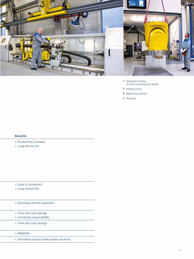
Benefits
+ Productivity increase
+ Long service life
+ Ease of movement
+ Long service life
+ Extremely smooth operation
+ Time and cost savings
+ Combined responsibility
+ Time and cost savings
+ Reliability
+ Innovative product and system solutions
1 Assembly building for Voith universal joint shafts
2 Welding robot
3 Balancing machine
4 Shipping
43

6
Series Torque rangeMz [kNm]
Flange diametera [mm]
S 0.25 to 35 58 to 225
R 32 to 1 000 225 to 550
CH 260 to 19 440 350 to 1 400
E 1 600 to 14 000 590 to 1 220
2 Range
Voith high-performance universal joint shafts offer an ideal combination of torque capacity, torsional rigidity and deflection resistance. We supply stand ard universal joint shafts, customer-specific adaptations, as well as special designs. Technical consultation, simulation of torsional vibrations and measurement of operating parameters complete our range of services.

7
Features Applications
• Standard design of Voith universal joint shafts• Non-split bearing eyes thanks to single-piece forged flange yoke• Length compensation with involute profile
• Paper machinery• Pumps• General industrial machinery• Marine vessels• Rail vehicles• Test stands• Construction machinery and cranes
• High torque capacity• Optimized bearing life• Flange in friction and positive locking design (see page 9)• Length compensation with involute profile up to size 315; from size 350 with
SAE-profile (straight flank profile, see page 30); optional tripod• Optimized torsional rigidity and deflection resistance in a low-weight design• Particularly suitable for use with high-speed drives• Optional: Low-maintenance length compensation through use of plastic-
coated (Rilsan®) involute spline profile
• Rolling mill drives• Heavy-duty industrial drives• Paper machinery• Pumps• Marine vessels• Rail vehicles
• Very high torque capacity • Optimized bearing life• Flange with Hirth connection for transmitting maximum torque• Length compensation with SAE-profile (straight flank profile, see page 30)
• Rolling mill drives• Construction of heavy machinery• Paper machinery
• Maximum torque capacity• Optimized bearings for exceptionally demanding applications• Patented 2-piece flange yoke• Flange with Hirth connection for transmitting maximum torque• Length compensation with SAE profile (straight flank profile, see page 30)
• Heavy-duty rolling mill drives

8
3 Designs3.1 Center sections
Type Description
…TUniversal joint shaft with standard length compensation
…TLUniversal joint shaft with longer length compensation
…TKUniversal joint shaft with short length compensation
…TRUniversal joint shaft with tripod length compensation1
…FUniversal joint shaft without length compensation (fixed-length shaft)
…GKJoint coupling: short, separable joint shaft without length compensation
…FZIntermediate shaft with a joint head and bearing
…Z Intermediate shaft with double bearing
1 Technical data: Please request separate catalog

9
3.2 Flanges
Example R T 250.8 S 285 / 315 R 2 560
Series S, R, CH, E
Center-section designT, TL, TK, TR, F, GK, FZ, Z
Size
Flange designS, K, Q, H
Flange size input end / output end, see section 7.1 (Page 28)
Profile coating S: Steel (Standard) R: Rilsan®
Length lmin or lz min in mm
3.3 Type designations
Type Description
SFriction flange, torque transmission by a non-positive connection
QFlange with face key for torque transmission
Type Description
KFlange with split sleeves for torque transmission (DIN 15 451)
HFlange with Hirth coupling for torque transmission

10
22
1

11
1 Rolling mills (horizontal rolling stand)
2, 3 Rolling mills (edging mill stand)
4 Applications
33

12
2
1

13
1 Rail vehicle drives
2 Paper machines
3 Marine propulsion
4 Pumps
5 Test stands
6 Special drives (mine hoist)
4
6
3
5

14
5 Definitions and abbreviations5.1 Lengths
Universal joint shaft with length compensation
lB : Operating length (to be specified when ordering)
lz : Shortest length of the universal joint shaft (fully collapsed)
lv : Available length compensation
The distance between the driving and the driven machines, together with any length changes during operation, deter mines the operating length:
Optimal operating length: lB,opt ≈ lz + lv __ 3
Maximum permissible operating length: lB,max = lz + lv
Universal joint shaft without length compensation
lB : Operating length, which corresponds to the universal joint shaft length l (to be specified when ordering)
lB,max
lz lv lB (=l)

15
5.2 Torque loads
Designation Explanation
Components
MDW This is the reversing fatigue torque rating. The shaft will have an infinite fatigue life up to this torque level.
MDS This is the pulsating, one-way fatigue torque rating. The shaft will have infinite fatigue life up to this torque level.Here: MDS ≈ 1.5 · MDW
MK Maximum permissible torque. If this level is exceeded, plastic deformation may occur.
Bearing
MZ The permissible torque for rarely occuring peak loads. At torque levels in excess of MZ, the bearing tracks might suffer plastic deformation. This can lead to a reduced bearing life.
Flanged connections
Individually designed
Note
MDW , MDS and MZ are load limits for the universal joint shaft. In the case of torque values that are close to the load limit, the transmission capability of the flange connection needs to be checked, especially when Hirth couplings are not being used.
Torque definitions
M (t)
MDS
MDW
0t

16
General specifications ST1
Size Mz
[kNm]
MDW
[kNm]
CR
[kNm]
ßmax
[°]
a k b ± 0.1 c H7 h C12 lm r t z g LA lv
058.1 0.25 0.08 0.09 30 58 52 47 30 5 30 28 x 1.5 1.5 4 3.5 A, B 25
065.1 0.52 0.16 0.16 30 65 60 52 35 6 32 32 x 1.5 1.7 4 4 A, B 30
075.1 1.2 0.37 0.23 30 75 70 62 42 6 36 40 x 2 2.2 6 5.5 A, B 35
090.2 2.2 0.68 0.44 20 90 86 74.5 47 8 42 50 x 2 2.5 4 6 A. B, C 40
100.2 3.0 0.92 0.62 20 100 98 84 57 8 46 50 x 3 2.5 6 7 A, B, C 40
120.2 4.4 1.3 0.88 20 120 115 101.5 75 10 60 60 x 4 2.5 8 8 A, B, C 60
120.5 5.4 1.6 1.4 20 120 125 101.5 75 10 60 70 x 4 2.5 8 9 A, B, C 60
150.2 7.1 2.2 2.0 20 150 138 130 90 12 65 80 x 4 3 8 10 C 110
150.3 11 3.3 2.6 35 150 150 130 90 12 90 90 x 4 3 8 12 C 110
150.5 13 4.3 3.3 24 150 158 130 90 12 86 100 x 5 3 8 12 C 110
180.5 22 6.7 4.6 30 180 178 155.5 110 14 96 110 x 6 3.6 8 14 C 110
225.7 35 11 6.9 30 225 204 196 140 16 110 120 x 6 5 8 15 C 140
Dimensions in mm 1 Longer lv on request
6 Technical data6.1 S Series
SF SGK
lfi xl

17
LA: Length compensation A: without profile guard
B: with profile guardC: Rilsan® coating with profile guard
STK 1 STK 2 STK 3 STK 42 SF SGK SFZ SZ SFZ, SZ
Iz min LA lv Iz fix LA lv Iz fix LA lv Iz fix LA lv Iz fix Imin Ifix Imin Imin Id d ga ta
240 B 25 215 B 25 195 B 25 175 B 20 165 160 120 - - - - - -
260 B 30 235 B 30 220 B 30 200 B 20 180 165 128 - - - - - -
300 B 35 270 B 35 250 B 35 225 B 25 200 200 144 - - - - - -
350 B, C 40 310 B, C 40 280 B, C 40 250 B, C 25 225 216 168 - - - - - -
375 B, C 40 340 B, C 40 310 B, C 40 280 B, C 30 255 250 184 - - - - - -
475 B, C 60 430 B, C 60 400 B, C 50 360 B, C 35 325 301 240 - - - - - -
495 B, C 60 450 B, C 60 420 B, C 50 375 B, C 35 345 307 240 - - - - - -
550 C 80 490 C 80 460 C 80 400 C 40 360 345 260 - - - - - -
745 C 110 680 C 110 640 C 80 585 C 40 545 455 360 - - - - - -
660 C 110 600 C 80 555 C 45 495 C 40 400 430 344 - - - - - -
740 C 110 650 C 60 600 C 45 560 C 60 500 465 384 - - - - - -
830 C 110 720 C 80 650 C 55 600 C 40 550 520 440 533 586 171 80 25 4
2 shorter lZ upon request
ld
ød
ld
l l
ta ta
ga ga
ød
ST / STK
SFZ SZ
lz
t
lm
lv
g
øh øh øh
øb
øc
øk ør
øb
z = 4
45° 45°
øb
z = 6
øb
z = 8
22.5°45°
øa
18
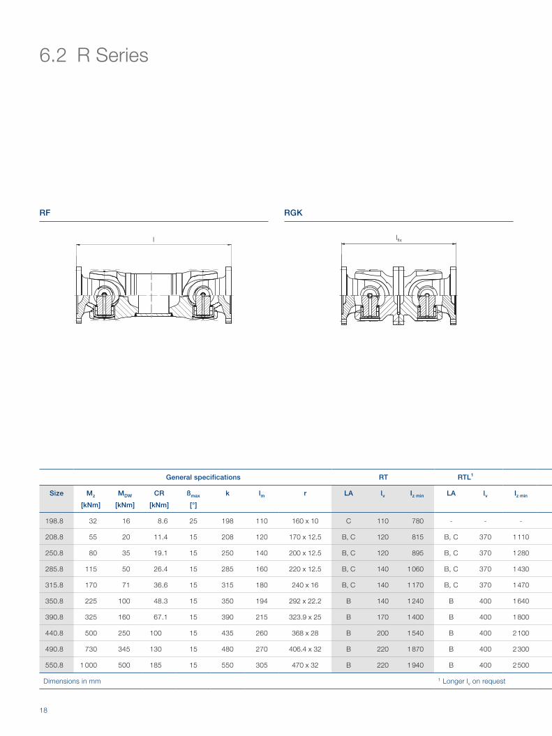
General specifications RT RTL1
Size Mz
[kNm]
MDW
[kNm]
CR
[kNm]
ßmax
[°]
k lm r LA lv Iz min LA lv Iz min
198.8 32 16 8.6 25 198 110 160 x 10 C 110 780 - - -
208.8 55 20 11.4 15 208 120 170 x 12.5 B, C 120 815 B, C 370 1 110
250.8 80 35 19.1 15 250 140 200 x 12.5 B, C 120 895 B, C 370 1 280
285.8 115 50 26.4 15 285 160 220 x 12.5 B, C 140 1 060 B, C 370 1 430
315.8 170 71 36.6 15 315 180 240 x 16 B, C 140 1 170 B, C 370 1 470
350.8 225 100 48.3 15 350 194 292 x 22.2 B 140 1 240 B 400 1 640
390.8 325 160 67.1 15 390 215 323.9 x 25 B 170 1 400 B 400 1 800
440.8 500 250 100 15 435 260 368 x 28 B 200 1 540 B 400 2 100
490.8 730 345 130 15 480 270 406.4 x 32 B 220 1 870 B 400 2 300
550.8 1 000 500 185 15 550 305 470 x 32 B 220 1 940 B 400 2 500
Dimensions in mm 1 Longer lv on request
6.2 R Series
lfi xl
RF RGK

19
LA: Length compensationB: with profile guardC: Rilsan® coating with profile guard
RTK 1 RTK 22 RF RGK RFZ RZ RFZ, RZ
LA lv Iz fix LA lv Iz fix Imin Ifix Imin Imin ld d ga ta
- - - - - - 480 440 535 568 171 80 25 4
B, C 100 725 B, C 80 640 520 480 626 732 229 90 32 5
B, C 110 800 B, C 70 735 620 560 716 812 251 110 34 6
B, C 120 960 B, C 100 880 720 640 804 883 277 130 42 6
B, C 120 1 070 B, C 100 980 805 720 912 1 019 316.5 160 45 7
B 130 1 160 B 110 1 070 855 776 980 1 087 344.5 200 48 7
B 150 1 280 B 100 1 200 955 860 1 023 1 091 346.5 200 48 9
B 170 1 380 B 100 1 300 1 155 1 040 - - - - - -
B 200 1 680 B 170 1 520 1 205 1 080 - - - - - -
B 170 1 775 B 100 1 680 1 355 1 220 - - - - - -
2 Shorter lz on request Flange dimensions: Pages 20 to 23
lz
lm
lv
øk
ør
ld
ød
l
ta
ga
ld
l
ta
ga
ød
RFZ
RT / RTL / RTK
RZ

20
S flange: friction flange
k1 a b ± 0.2 c H7 g h C12 t z Note
198
225 196 140 15 16 5 8 Standard
250 218 140 18 18 6 8
285 245 175 20 20 7 8
208
225 196 140 15 16 5 8 Torque MDW = 18 kNm
250 218 140 18 18 6 8 Standard
285 245 175 20 20 7 8
315 280 175 22 22 7 8
250
250 218 140 18 18 6 8 Torque MDW = 25 kNm
285 245 175 20 20 7 8 Standard
315 280 175 22 22 7 8
350 310 220 25 22 8 10
285
285 245 175 20 20 7 8 Torque MDW = 36 kNm
315 280 175 22 22 7 8 Standard
350 310 220 25 22 8 10
390 345 250 32 24 8 10
315
315 280 175 22 22 7 8 Torque MDW = 52 kNm
350 310 220 25 22 8 10 Standard
390 345 250 32 24 8 10
435 385 280 40 27 10 10
350
350 310 220 25 22 8 10 Torque MDW = 75 kNm
390 345 250 32 24 8 10 Standard
435 385 280 40 27 10 10
390390 345 250 32 24 8 10 Torque MDW = 100 kNm
435 385 280 40 27 10 10 Standard
Dimensions in mm. Additional flanges on request.1 Rotation diameter of the universal joint shaft.
økøcøbøb øb
øa
z = 8 z = 10
øht
g
øh
22.5° 36°
45° 36°

21
Q flange: flange with face key
k1 a b ± 0.2 c H7 g h t x h9 y z Note
208
225 196 105 20 17 5 32 9 8 Standard
250 218 105 25 19 6 40 12.5 8
285 245 125 27 21 7 40 15 8
250
250 218 105 25 19 6 40 12.5 8 Standard
285 245 125 27 21 7 40 15 8
315 280 130 32 23 8 40 15 10
285
285 245 125 27 21 7 40 15 8 Standard
315 280 130 32 23 8 40 15 10
350 310 155 35 23 8 50 16 10
315
315 280 130 32 23 8 40 15 10 Standard
350 310 155 35 23 8 50 16 10
390 345 170 40 25 8 70 18 10
350
350 310 155 35 23 8 50 16 10 Standard
390 345 170 40 25 8 70 18 10
435 385 190 42 28 10 80 20 16
390
390 345 170 40 25 8 70 18 10 Standard
435 385 190 42 28 10 80 20 16
480 425 205 47 31 12 90 22.5 16
440
435 385 190 42 28 10 80 20 16 Standard
480 425 205 47 31 12 90 22.5 16
550 492 250 50 31 12 100 22.5 16
490480 425 205 47 31 12 90 22.5 16 Standard
550 492 250 50 31 12 100 22.5 16
550 550 492 250 50 31 12 100 22.5 16 Standard
Dimensions in mm. Additional fl anges on request.1 Rotation diameter of the universal joint shaft.
z = 8 z = 10 z = 16
øh øh øh
22.5° 10° 20°30°
45°30°
20°
øb øb øb
øa
øb
øc x øk
t
y
g
22
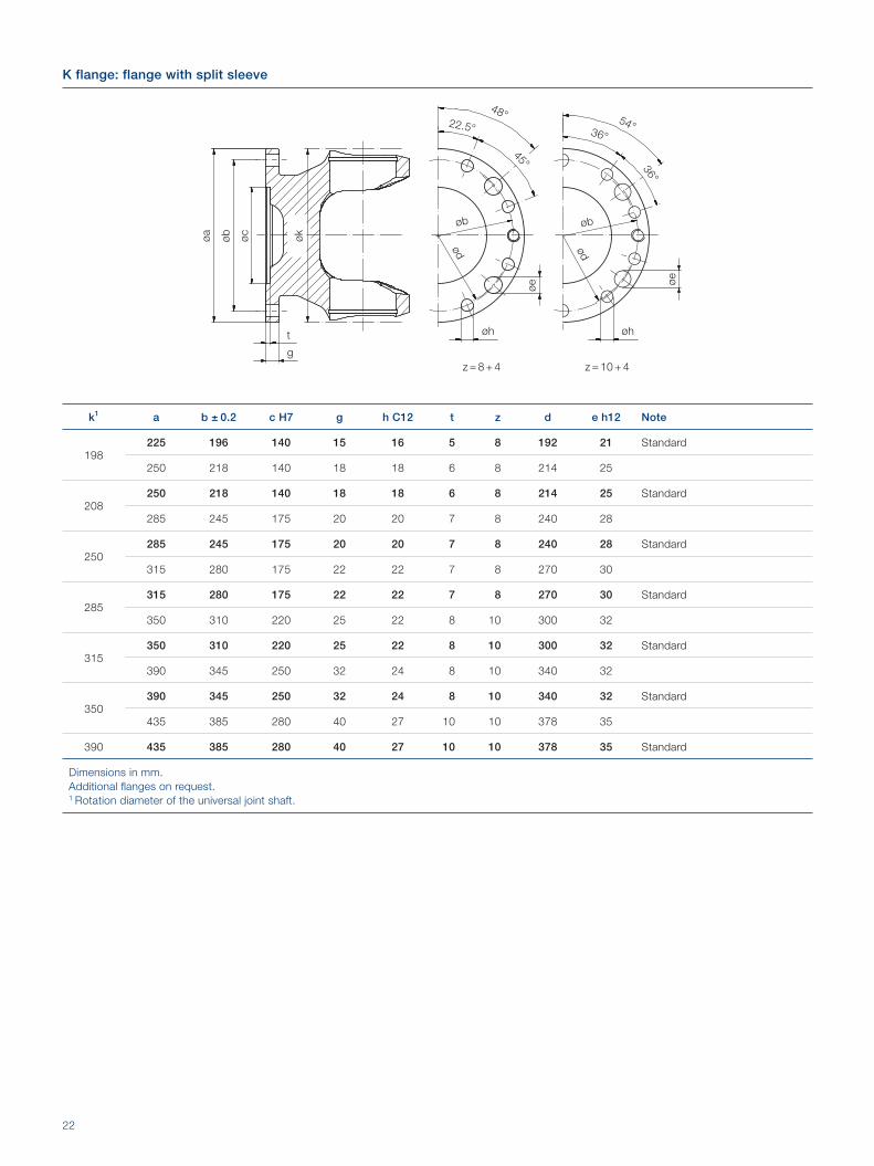
K flange: flange with split sleeve
k1 a b ± 0.2 c H7 g h C12 t z d e h12 Note
198225 196 140 15 16 5 8 192 21 Standard
250 218 140 18 18 6 8 214 25
208250 218 140 18 18 6 8 214 25 Standard
285 245 175 20 20 7 8 240 28
250285 245 175 20 20 7 8 240 28 Standard
315 280 175 22 22 7 8 270 30
285315 280 175 22 22 7 8 270 30 Standard
350 310 220 25 22 8 10 300 32
315350 310 220 25 22 8 10 300 32 Standard
390 345 250 32 24 8 10 340 32
350390 345 250 32 24 8 10 340 32 Standard
435 385 280 40 27 10 10 378 35
390 435 385 280 40 27 10 10 378 35 Standard
Dimensions in mm.Additional fl anges on request.1 Rotation diameter of the universal joint shaft.
øk
øc
øb
øb øb
øa
z = 8 + 4 z = 10 + 4
48°54°
øht
g
øh
øe ø
e
ød ød
22.5° 36°
45° 36°

23
H flange: Flange with Hirth connections
k1 a b ± 0.2 c g h C12 u2 z Note
208225 196 180 20 18 48 4 Standard
250 218 200 25 20 48 4
250250 218 200 25 20 48 4 Standard
285 245 225 27 21 60 4
285285 245 225 27 21 60 4 Standard
315 280 250 32 23 60 4
315315 280 250 32 23 60 4 Standard
350 310 280 35 24 72 6
350350 310 280 35 24 72 6 Standard
390 345 315 40 25 72 6
390390 345 315 40 25 72 6 Standard
435 385 345 42 28 96 6
440435 385 345 42 28 96 6 Standard
480 425 370 47 31 96 8
490480 425 370 47 31 96 8 Standard
550 492 440 50 32 96 8
550 550 492 440 50 32 96 8 Standard
Dimensions in mm.Bore on internal gear tooth.Additional fl anges on request.1 Rotation diameter of the universal joint shaft.2 Number of teeth of Hirth coupling.
øk
øc
øb
øb øb øb
øa
z = 4 z = 6 z = 8
45°60°
22.5°
45°
øh øh øhg
24
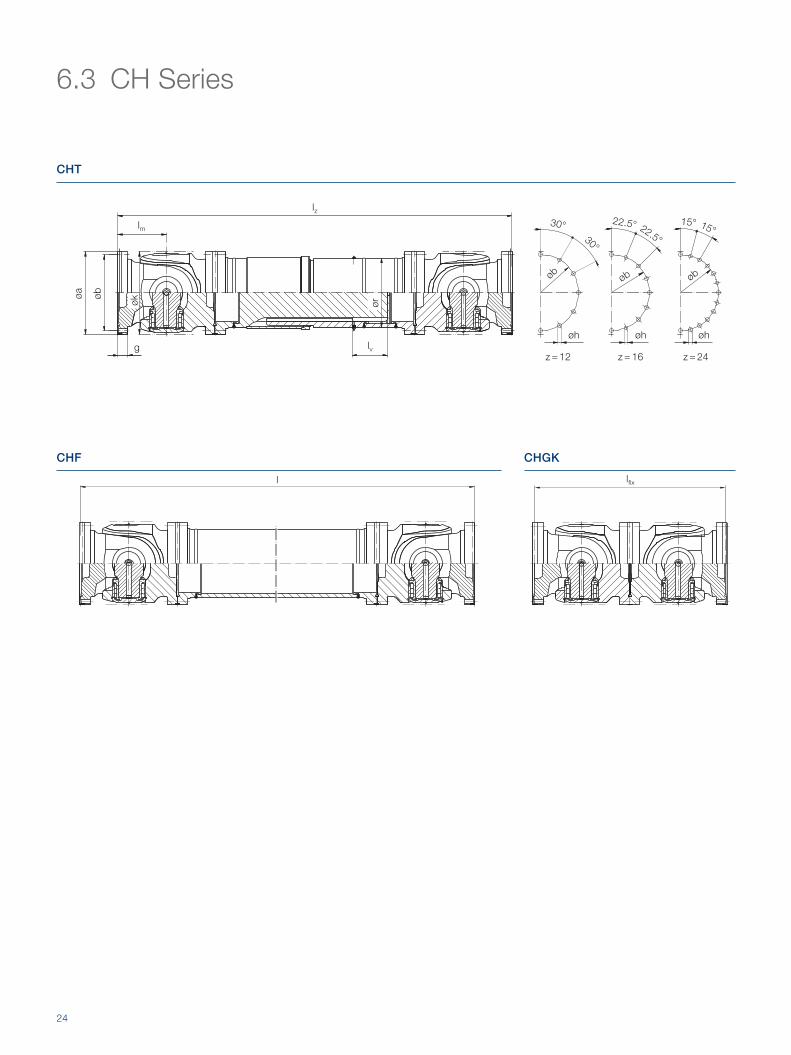
6.3 CH Series
l lfi x
lz
lm
lvg
øa
øb
øk
ør
z = 12
30°
øb
z = 16
30°
øb
22.5° 22.5°
z = 24
øb
15°15°
CHT
CHF CHGK
øhøhøh

25
LA: Length compensationA: without profile guard
General specifications CHT2 CHF2 CHGK
Size Mz1
[kNm]MDW
1
[kNm]CR
[kNm]ßmax
[°]a k b ± 0.2 h lm r z g LA lv Iz min Imin Ifix
350.8 260 140 48.3 10 350 350 320 17.5 210 292 x 22.2 12 45 B 170 1 684 1 050 840
390.8 350 190 67.1 10 390 390 355 20 230 323.9 x 25 12 50 B 170 1 874 1 160 920
440.8 560 280 100 10 440 440 405 20 260 368 x 28 16 55 B 190 2 104 1 300 1 040
490.8 730 390 130 10 490 490 450 22 290 406.4 x 32 16 60 B 210 2 344 1 460 1 160
550.8 1 010 560 185 10 550 550 510 24 330 470 x 32 16 70 B 250 2 644 1 620 1 320
590.40 1 330 890 212 10 580 590 535 26 350 508 x 50 24 75 B 250 2 784 1 740 1 400
620.40 1 430 1 030 228 10 610 620 565 26 370 508 x 50 24 75 B 250 2 864 1 820 1 480
650.40 1 800 1 190 284 10 640 650 590 30 390 558.8 x 55 24 80 B 250 3 034 1 940 1 560
680.40 1 920 1 360 304 10 670 680 620 30 405 558.8 x 55 24 80 B 250 3 094 2 000 1 620
710.40 2 390 1 550 362 10 700 710 645 33 420 609.6 x 60 24 90 B 250 3 284 2 100 1 680
740.40 2 550 1 760 385 10 730 740 675 33 440 609.6 x 60 24 90 B 250 3 364 2 180 1 760
770.40 3 150 1 980 472 10 760 770 700 36 460 660.4 x 65 24 95 B 250 3 554 2 300 1 840
800.40 3 330 2 220 500 10 790 800 730 36 480 762 x 60 24 95 B 250 3 634 2 400 1 920
830.40 4 090 2 480 588 10 820 830 765 39 500 762 x 60 24 105 2 000
860.40 4 310 2 760 620 10 850 860 795 39 510 790 x 85 24 105 2 040
890.40 5 050 3 060 706 10 880 890 805 45 535 790 x 85 24 115 2 140
920.40 5 300 3 380 742 10 910 920 835 45 550 790 x 85 24 120 2 200
950.40 6 070 3 720 847 10 940 950 865 45 570 790 x 85 24 120 2 280
980.40 6 360 4 080 887 10 970 980 895 45 580 865 x 90 24 120 2 320
1 010.40 7 340 4 470 1 015 10 1000 1 010 920 45 590 865 x 90 24 130 2 360
1 040.40 7 660 4 880 1 060 10 1030 1 040 940 52 620 865 x 90 24 135 2 480
1 070.40 7 880 5 170 1 090 10 1060 1 070 975 52 640 915 x 90 24 135 2 560
1 090.40 9 100 5 620 1 275 10 1080 1 090 995 52 660 966 x 90 24 145 2 640
1 120.40 9 480 6 090 1 328 10 1110 1 120 1 025 52 670 1 000 x 90 24 145 2 680
1 170.40 11 620 6 940 1 592 10 1160 1 170 1 065 62 700 1 000 x 90 24 150 2 800
1 200.40 12 070 7 490 1 654 10 1190 1 200 1 095 62 720 1 100 x 90 24 150 2 880
1 250.40 14 010 8 480 1 889 10 1240 1 250 1 145 62 740 1 100 x 90 24 160 2 960
1 280.40 14 510 9 100 1 957 10 1270 1 280 1 175 62 760 1 200 x 90 24 160 3 040
1 320.40 16 570 9 980 2 215 10 1310 1 320 1 215 62 790 1 200 x 90 24 170 3 160
1 360.40 17 330 10 920 2 316 10 1350 1 360 1 255 62 815 1 300 x 90 24 170 3 260
1 400.40 19 440 11 910 2 583 10 1390 1 400 1 285 70 840 1 300 x 90 24 180 3 360
Dimensions in mm.From size 350.8 to 550.8 without internal bearing ring.
1 Values for forged components. 2 From size 830.40 to customer specification.
26
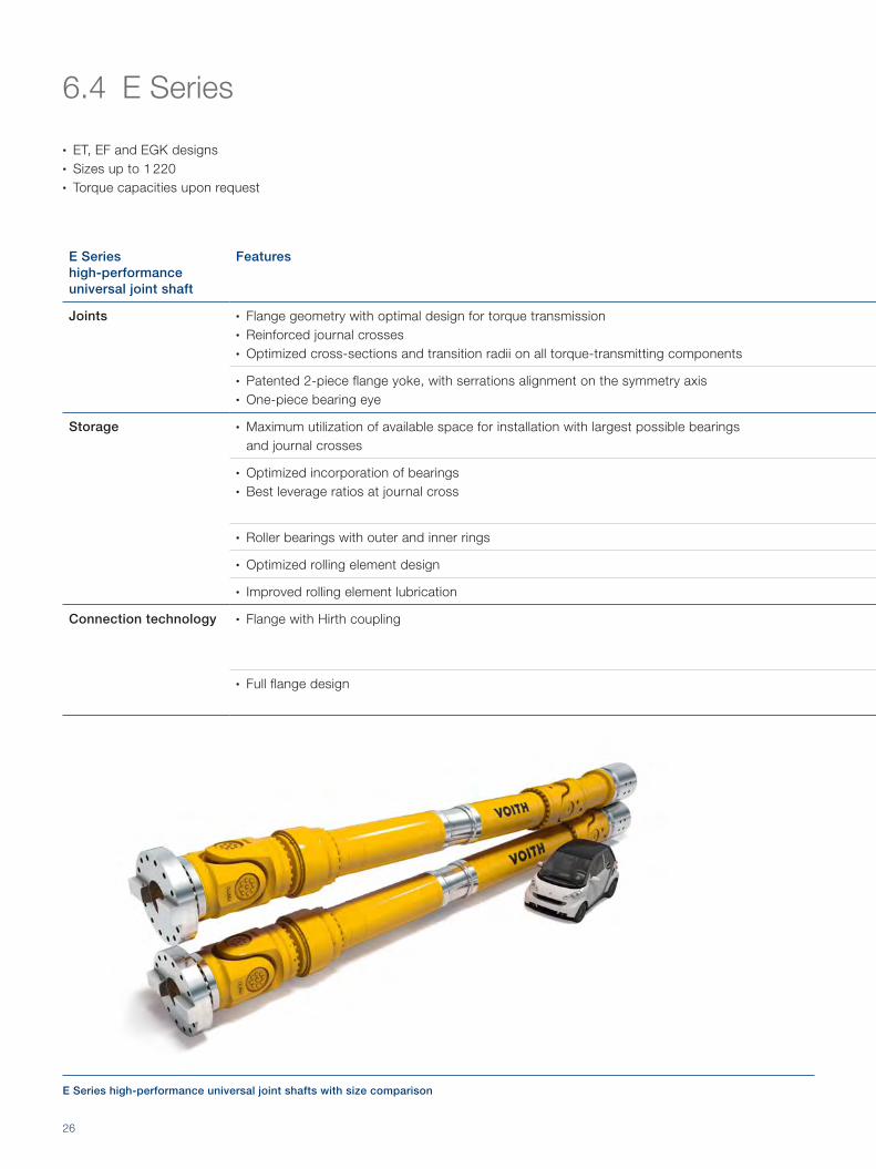
6.4 E Series
E Series high-performance universal joint shaft
Features
Joints • Flange geometry with optimal design for torque transmission• Reinforced journal crosses• Optimized cross-sections and transition radii on all torque-transmitting components
• Patented 2-piece flange yoke, with serrations alignment on the symmetry axis• One-piece bearing eye
Storage • Maximum utilization of available space for installation with largest possible bearings and journal crosses
• Optimized incorporation of bearings• Best leverage ratios at journal cross
• Roller bearings with outer and inner rings
• Optimized rolling element design
• Improved rolling element lubrication
Connection technology • Flange with Hirth coupling
• Full flange design
• ET, EF and EGK designs• Sizes up to 1 220• Torque capacities upon request
E Series high-performance universal joint shafts with size comparison

27
E Series high-performance universal joint shaft
Features Advantages Benefits
Joints • Flange geometry with optimal design for torque transmission• Reinforced journal crosses• Optimized cross-sections and transition radii on all torque-transmitting components
• Significantly higher torque capacity than with previous universal joint shaft designs
• Optimized to withstand torque peaks
+ Productivity increase + Long service life + Reduced maintenance costs + Capability to roll higher strength steels
• Patented 2-piece flange yoke, with serrations alignment on the symmetry axis• One-piece bearing eye
• Heavy-duty cross-sections without joints or bolts
Storage • Maximum utilization of available space for installation with largest possible bearings and journal crosses
• Increased bearing life and capability to withstand high static and dynamic loads
• Optimized incorporation of bearings• Best leverage ratios at journal cross
• Long bearing life• Uniformed load distribution throughout bearing• Capability to withstand high static and dynamic loads
• Roller bearings with outer and inner rings • Individually replaceable cartridge style roller bearings
• Optimized rolling element design • Optimized to withstand torque peaks
• Improved rolling element lubrication • Improved hydrodynamic lubrication
Connection technology • Flange with Hirth coupling • Reliable transmission of the highest torques• Optimal centering• Easy to assemble
+ Low assembly and maintenance costs + Productivity increase
• Full flange design • No weakening of components as a result of necking or reduced cross-sections
+ Capability to roll higher strength steels + Able to withstand overloads
Three-dimensional, sectioned model of an E Series joint

28
Journal cross
Flange yoke
Welded yoke
Tube
Splined hub
7 Engineering basics7.1 Major components of a Voith universal joint shaft
Hub yoke, output end
Design

29
Splined journal
Profi le guardDirt scraper
Welded yoke
Flange yoke
Journal cross set
7 Engineering basics7.1 Major components of a Voith universal joint shaft
Irrespective of their series, all versions and sizes of Voith uni-v er sal joint shafts share many of the same common at tri -butes that contribute to ensuring reliable operation:• Yokes and flange yokes with optimized geometry• Drop-forged journal crosses• Low maintenance roller bearings with maximum load
capacity• Use of high-strength tempering and hardened steels• Optimal welded joints
Shaft yoke, input end
Design

30
7.2 Telescopic length compensation
1 SAE profi le (straight fl ank profi le)
2 Involute profi le
21
For many applications, length compensation of the universal joint shaft is required. In comparison with other driveline products, in the case of universal joint shafts, length compe-nsation is achieved by the center section and offset by the universal joints.
Two types of length compensation are used in Voith universal joint shafts: the SAE profile (straight flank profile) and the involute profile. The universal joint shaft series and size deter mine the type of length compensation.
For smaller universal joint shafts, which typically experience lower loads, the involute profile is a suitable solution with a good cost-benefit ratio. The SAE profile (straight flank profile) is a better solution for large, high-performance universal joint shafts.

31
Length compensation with SAE profile (straight flank profile)
Features Advantages Benefits
• Straight flank, diameter-centered profile
• Separation of torque transmission and centering functions
+ Long service life
• Almost orthogonal introduction of force
• Lower normal forces and thus lower displacement forces
+ Ease of movement
• Large contact surfaces • Low surface pressure + Long service life
• Favorable pairing of materials for hub and spline shaft
• Spline shaft nitrated as standard
• High wear resistance + Long service life
• Patented lubrication mechanism in the grease distribution groove for uniform distribution of grease across the full diameter of the profile
• Tooth shape incorporates lubri ca-tion reservoir for reliable supply of lubricant to sliding surfaces
+ Extended maintenance intervals
SAE-profile (straight flank profile)
Involute profile
FN ≈ FU
FN > FU
FU
SAE-profile (straight flank profile)
Involute profile
Centering function
Torque transmission
Force introduced during torque transmission Torque transmission and centering
32
W1
�
G1
W2
�2
M1, �1
M2, �2
�1
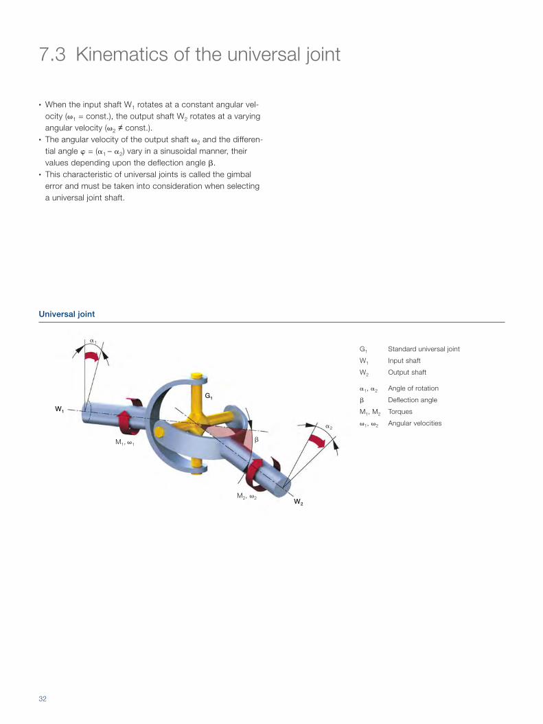
G1 Standard universal joint
W1 Input shaft
W2 Output shaft
�1, �2 Angle of rotation
� Deflection angle
M1, M2 Torques
�1, �2 Angular velocities
Universal joint
7.3 Kinematics of the universal joint
• When the input shaft W1 rotates at a constant angular vel-ocity (�1 = const.), the output shaft W2 rotates at a varying angular velocity (�2 ≠ const.).
• The angular velocity of the output shaft �2 and the differen-tial angle � = (�1 – �2) vary in a sinusoidal manner, their values depending upon the deflection angle �.
• This characteristic of universal joints is called the gimbal error and must be taken into consideration when selecting a universal joint shaft.

33
� = 12°
� = 12°
� = 6°
� = 6°
�1
�
� � � � �
l�maxlfor � = 12°
1 – cos 12°
0.8°
0.4°
0°
-0.4°
-0.8°
1.02
1.01
1.00
0.99
0.98
0° 90° 180° 270° 360°
• With one rotation of the shaft W1, the differential angle � changes four times, as does the angular velocity �2.
• During the course of one rotation, the shaft W2 twice passes through the points of maximum acceleration and deceleration.
• At larger deflection angles � and higher velocities, con-siderable forces can be generated.
The following equations apply:
� = �1 – �2 (1)
tan �1 ______ tan �2
= cos � (2)
tan � = tan �1 · (cos � – 1)
_________________ 1 + cos � · tan2 �1
(3)
This gives the ratio of the angular velocities between the two shafts W1 and W2:
�2 __ �1
= cos �
_______________ 1 – sin2 � · sin2 �1
(4)
change to maximum:
�2 ___ �1
| max = 1 _____ cos � at �1 = 90° and �1 = 270° (4a)
change to minimum:
�2 ___ �1
| min = cos � at �1 = 0° and �1 = 180° (4b)
As regards the torque ratio, the following equation applies:
M2 ___ M1
= �1 ___ �2
(5)
change to maximum:
M2 ___
M1 | max
= 1 ______ cos � at �1 = 90° and �1 = 270° (5a)
change to minimum:
M2 ___ M1
| min = cos � at �1 = 0° and �1 = 180° (5b)
Movement relation

34
One indicator of the variation is the variation factor U:
U = �2 ___ �1
| max –
�2 ___ �1
| min = 1 _____ cos � – cos � = tan � · sin � (6)
Finally, as regards to the maximum differential angle �max the following equation applies:
tan �max = ± 1 – cos �
_________ 2 · √
_____ cos � (7)
U�max
�max
4.4°
4.0°
3.6°
3.2°
2.8°
2.4°
2.0°
1.6°
1.2°
0.8°
0.4°
0.44
0.40
0.36
0.32
0.28
0.24
0.20
0.16
0.12
0.08
0.04
0° 3° 6° 9° 12° 15° 18° 21° 24° 27° 30°
U
�
Variation factor, differential angle
All of the components of the universal joint shaft should lie in one plane
A
Conclusions
A single universal joint should only be used if the following requirements are met:• The variation in the rotational speed of the output shaft
is of secondary importance• The deflection angle is very small (� < 1°)• The forces transmitted are low
G1
G2

35
Conditions for the synchronous rotation of the input and output shafts:The three conditions A, B and C ensure that joint G2 operates with a phase shift of 90° and fully compensates for the gimbal error of joint G1. This universal joint shaft arrangement is known as the ideal universal joint shaft arrangement with complete motion compensation.
7.4 Double universal joints
Section 7.3 shows that the output shaft W2 always rotates at the varying angular velocity �2 when connected via a single universal joint at a given deflection angle �.
Universal joint shaft in Z-arrangement, the input and output shafts lie parallel to each other in one plane
Both yokes of the center section of the shaft lie in one planeThe deflection angles �1 and �2 of the two joints are identical
Universal joint shaft in W-arrangement, the input and output shafts lie parallel to each other in one plane
If, however, two universal joints G1 and G2 are connected to-gether correctly in the form of a universal joint shaft in a Z- or W-arrangement, the variations in the speeds of the input and output shaft fully cancel each other out.
This is the arrangement to be aiming for. If just one of the three conditions is not satisfied, then the universal joint shaft no longer operates at constant input and output speeds, i.e. it no longer operates homo-kinetically. In such cases, please contact your Voith Turbo representative.
CB
�2
�1 �2 �1
B
G1
G2
�1
�2
G1
G2

36
Maximum values for radial bearing forces on universal joint shafts in a Z-arrangement
a b
Md
A B
L
�1
�2
E F
e fG1
G2
�1 ≠ �2 �1 = �2
�1 = 0°
B1 F1
A1 E1
A1 = Md · b · cos �1 _________
L · a · (tan �1 – tan �2)
B1 = Md · (a + b) · cos �1 _____________
L · a · (tan �1 – tan �2)
E1 = Md · (e + f) · cos �1 ____________
L · f · (tan �1 – tan �2)
F1 = Md · e · cos �1 _________
L · f · (tan �1 – tan �2)
A1 = 0
B1 = 0
E1 = 0
F1 = 0
�1 = 90°
B2 E2
A2 F2
A2 = Md · tan �1 ______ a
B2 = Md · tan �1 ______ a
E2 = Md · sin �2 ________
f · cos �1
F2 = Md · sin �2 ________
f · cos �1
A2 = Md · tan �1 ______ a
B2 = Md · tan �1 ______ a
E2 = Md · tan �1 ______
f
F2 = Md · tan �1 ______
f
7.5.1 Radial bearing forcesDue to the deflection of the universal joint shaft, the connection bearings are also subjected to radial loads. The radial forces on the bearings vary from no forces to their maximum, twice per revolution.
7.5 Bearing forces on input and output shafts

37
Maximum values for radial bearing forces on universal joint shafts in a W-arrangement
ab
Md
AB
L
�1 �2
EF
ef
G1 G2
�1 ≠ �2 �1 = �2
�1 = 0°
B1 F1
A1 E1
A1 = Md · b · cos �1 _________
L · a · (tan �1 – tan �2)
B1 = Md · (a + b) · cos �1 _____________
L · a · (tan �1 – tan �2)
E1 = Md · (e + f) · cos �1 ____________
L · f · (tan �1 – tan �2)
F1 = Md · e · cos �1 _________
L · f · (tan �1 – tan �1)
A1 = 2 · Md · b · sin �1 ________
L · a
B1 = 2 · Md · (a + b) · sin �1 ____________
L · a
E1 = 2 · Md · (e + f) · sin �1 ____________
L · f
F1 = 2 · Md · e · sin �1 ________
L · f
�1 = 90°
B2 F2
A2 E2
A2 = Md · tan �1 ______ a
B2 = Md · tan �1 ______ a
E2 = Md · sin �2 ________
f · cos �1
F2 = Md · sin �2 ________
f · cos �1
A2 = Md · tan �1 ______ a
B2 = Md · tan �1 ______ a
E2 = Md · tan �1 ______
f
F2 = Md · tan �1 ______
f
Designations and formulasG1, G2 Universal jointsA, B, E, F Connection bearingMd Input torqueA1/2, B1/2, E1/2, F1/2 Bearing forces�1 Angle of rotation�1, �2 Deflection angle

38
7.5.2 Axial bearing forcesIn principle, the kinematics of a universal joint shaft do not generate any axial forces. However, axial forces that need to be absorbed by adjacent bearings occur in universal joint shafts with length compensation for two reasons:
1. Force Fax, 1 as a result of friction in the length compensa-tion assemblyAs the length changes during the transmission of torque, fric-tion is generated between the flanks of the spline profiles in the length compensation assembly. The frictional force Fax,1, which acts in an axial direction, can be calculated using the following equation:
Fax,1 = � · Md · 2 ___
dm · cos �
where:� Coefficient of friction; � ≈ 0.11 to 0.14 for steel against steel (lubricated) � ≈ 0.07 for Rilsan® plastic coating against steelMd Input torquedm Pitch circle diameter of the spline profile� Deflection angle
2. Force Fax, 2 as a result of the pressure build-up in the length compensation assembly during lubricationDuring the lubrication of the length compensation assembly, an axial force Fax, 2 , occurs which depends on the force ap-plied while lubricating. Please note that information on this subject is available in the installation and operating instructions.
1 Balancing machine
2 Balancing of universal joint shafts
21

39
Type of machine – general examples Balance quality level G
Complete piston engines for cars, trucks and locomotives G 100
Cars: wheels, rims, wheel sets, universal joint shafts; crank drives with mass balancing on elastic mounts
G 40
Agricultural machinery; crank drives with mass balancing on rigid mounts; size reduction machinery; input shafts (cardan shafts, propeller shafts)
G 16
Jet engines; centrifuges; electric motors and generators with a shaft height of at least 80 mm and a maximum rated speed of up to 950 rpm; electric motors with a shaft height of less than 80 mm; fans; gearboxes; general industrial machinery; machine tools; paper machinery; process engineering equipment; pumps; turbochargers; hydro-power turbines
G 6.3
Compressors; computer drives; electric motors and generators with a shaft height of at least 80 mm and a maximum rated speed of over 950 rpm; gas turbines, steam turbines; machine tool drives; textile machinery
G 2.5
7.6 Balancing of universal joint shafts
As with any other torque transmitting shaft, a universal joint shaft also has a non-uniform distribution of mass around the axis of rotation. This leads to unbalanced forces during oper-ation wich has to be compensated depending on the case of application. Depending on the operating speed and the spe-ci fic applica tion, Voith universal joint shafts are dynamically balanced in two planes.
The balancing procedure employed by Voith for universal joint shafts is based on that prescribed in DIN ISO 1 940-1 ("Mech-anical vibration – Balance quality requirements for rotors in a constant (rigid) state – Part 1: Specification and verification of balance tolerances"). An extract from this Standard lists the following approximate values for balance quality levels:
Depending on the application and maximum operating speed, the balance quality levels for universal joint shafts lie in the range between G 40 and G 6.3. The reproduction of the mea-surements can be subject to wider tolerances due to the influence of various physical factors. Such factors include:• Design characteristics of the balancing machine• Accuracy of the measuring method• Tolerances in the connections to the universal joint shaft• Radial and axial clearances in the universal joint bearings• Deflection clearance in length compensation
The benefits of balancing:
+ Prevention of vibrations and oscillations, resulting in
smoother operation
+ Longer service life of the universal joint shaft
40
8 Selection aids
The design of a universal joint shaft depends on a number of factors. Reliable, verified calculations and tests prevent any danger to the surrounding area. Consideration of the costs that arise over the entire product lifecycle also comes into play.
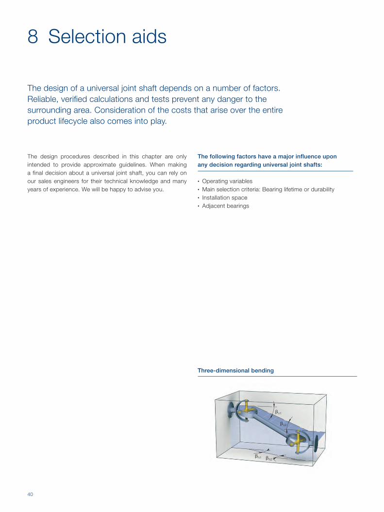
Three-dimensional bending
The design procedures described in this chapter are only intended to provide approximate guidelines. When making a final decision about a universal joint shaft, you can rely on our sales engineers for their technical knowledge and many years of experience. We will be happy to advise you.
The following factors have a major influence upon any decision regarding universal joint shafts:
• Operating variables• Main selection criteria: Bearing lifetime or durability• Installation space• Adjacent bearings
�v1
�h1
�v2
�h2

41
8.1 Definitions of operating variables
Des ig-nation
Usual unit
Explanation
PN [kW] Rated power of the drive motor
nN [rpm] Rated speed of the drive motor
MN [kNm] Rated torque of the drive motor, where:
MN = 60 _______ 2� · nN
· PN ≈ 9.55 · PN ___ nN
with MN in kNm, nN in rpm and PN in kW
ME [kNm] Equivalent torqueThis torque is an important operating variable if bearing lifetime is the main criterion in the selection of a universal joint shaft. It takes operating conditions into account and can be calculated for situa-tions involving combined loads (see section 8.2.1). If the operating conditions are not sufficiently known, the rated torque can be used as an initial estimate.
nE [rpm] Equivalent speedThis speed is an important operating variable if bearing lifetime is the main criteria in the selection of a universal joint shaft. It takes operating conditions into account and can be calculated for situa-tions involving combined loads (see section 8.2.1). If the operating conditions are not sufficiently known, the rated speed can be used as an initial estimate.
Mmax [kNm] Peak torqueThis is the maximum torque that occurs during normal operation.
nmax [rpm] Maximum speedThis is the maximum speed that occurs during normal operation.
nz1 [rpm] Maximum permissible speed as a function of the deflection angle during operationThe center section of a universal joint shaft in a Z- or W-arrangement (� ≠ 0°) rotates at a varying speed. It experiences a mass acceleration torque that depends upon the speed and the deflection angle. To ensure smooth operation and prevent excessive wear, the mass acceleration torque is limited by avoiding the exceeding of the maximum speed of the universal joint shaft nz1. For addi-tional information see section 8.3.1.
nz2 [rpm] Maximum permissible speed taking bending vibrations into accountA universal joint shaft is an elastic body when bent. At a critical bending speed (whirling speed), the frequency of the bending vibrations equals the natural frequency of the universal joint shaft. The result is a high load on all of the universal joint shaft components. The maximum speed of the universal joint shaft must be significantly lower than this critical speed. For additional information, see section 8.3.2.
� [°] Deflection angle during operationDeflection angle of the two joints in a Z or W-arrangement, where:
� = �1 = �2
If the situation involves three-dimensional deflection, the resulting deflection to angle �R can be determined thus:
tan �R = √_______________
tan2 �h + tan2 �V und es gilt: � = �R
�max [°] Maximum possible deflection angleThis is the deflection angle that occurs during normal operation.
42
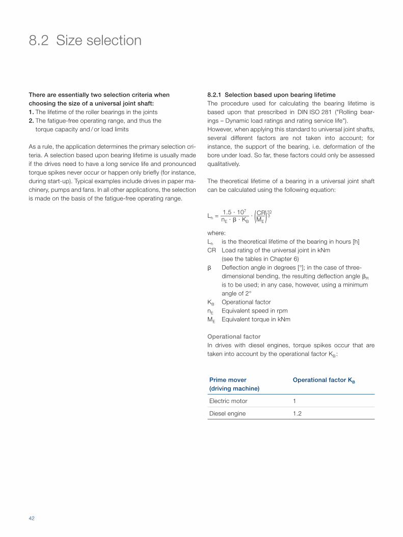
8.2.1 Selection based upon bearing lifetimeThe procedure used for calculating the bearing lifetime is based upon that prescribed in DIN ISO 281 ("Rolling bear-ings – Dynamic load ratings and rating service life"). However, when applying this standard to universal joint shafts, several different factors are not taken into account; for instance, the support of the bearing, i.e. deformation of the bore under load. So far, these factors could only be assessed qualitatively.
The theoretical lifetime of a bearing in a universal joint shaft can be calculated using the following equation:
Lh = 1.5 · 107
________ nE · � · KB
· ( CR ___ ME
) 10 ___ 3
where:Lh is the theoretical lifetime of the bearing in hours [h]CR Load rating of the universal joint in kNm
(see the tables in Chapter 6)� Deflection angle in degrees [°]; in the case of three-
dimensional bending, the resulting deflection angle �R is to be used; in any case, however, using a minimum angle of 2°
KB Operational factornE Equivalent speed in rpmME Equivalent torque in kNm
Operational factor
In drives with diesel engines, torque spikes occur that are taken into account by the operational factor KB :
Prime mover (driving machine)
Operational factor KB
Electric motor 1
Diesel engine 1.2
8.2 Size selection
There are essentially two selection criteria when choosing the size of a universal joint shaft:1. The lifetime of the roller bearings in the joints2. The fatigue-free operating range, and thus the
torque capacity and / or load limits
As a rule, the application determines the primary selection cri-teria. A selection based upon bearing lifetime is usually made if the drives need to have a long service life and pronounced torque spikes never occur or happen only briefly (for instance, during start-up). Typical examples include drives in paper ma-chinery, pumps and fans. In all other applications, the selection is made on the basis of the fatigue-free operating range.

43
n1
nu
Equivalent operating values
The equation for the theoretical lifetime of the bearing assumes a constant load and speed. If the load changes in increments, the equivalent operating values can be determined that produce the same fatigue as the actual loads. The equivalent operating values are ultimately the equivalent speed nE and the equivalent torque ME.If a universal joint shaft transmits the torque Mi for a time period Ti at a speed of ni, a time segment qi that normalizes the time period Ti with respect to the overall duration of operation Ttot is first defined:
qi = Ti ____
Ttot with ∑
i = 1
u
qi = q1 + q2 + … + qu = 1
In this way, the equivalent operating values can be determined:
nE = ∑ i = 1
u
qi · ni = q1 · n1 + q2 · n2 + … + qu · nu
ME = ( ∑ i = 1
u
qi · ni · M i 10 ___
3 ___________ nE
) 3 ___ 10
= ( q1 · n1 · M 1 10 ___ 3
+ q2 · n2 · M 2
10 ___ 3 + … + qu · nu · M u
10 ___ 3 _____________________________________ nE
) 3 ___ 10
Incremental variation of the load on a universal joint shaft
Conclusions
• The bearing's calculated lifetime is a theoretical value
that is usually signifi cantly exceeded.
• The following additional factors affect the lifetime of the
bearings, sometimes to a signifi cant degree:
− Quality of the bearings
− Quality (hardness) of the journals
− Lubrication
− Plastic deformation as a result of overloading
− Quality of the seals
M, n M1
M2
n2
Mu
q1 q2 quq0 1

44
8.2.2 Selection on the basis of fatigue-free operating rangeCalculations regarding the fatigue-free operating range can be made using a load spectrum. In practice though, sufficie-ntly accurate load spectra are seldom available. In this case, one needs to rely on the quasi-static dimensioning proce-dure. In this procedure, the expected peak torque Mmax is compared with the torques MDW , MDS and MZ (see section 5.2).
The following estimate is made for the peak torque:
Mmax ≈ K3 · MN
K3 is called the shock factor. These are empirical values based upon decades of experience in designing universal joint shafts.
The peak torque determined in this manner must meet the
following requirements:
1. Mmax ≤ MDW for alternating load
2. Mmax ≤ MDS for pulsating load
3. Individual and rarely occurring torque peaks must not
exceed the value MZ. The permissible duration and fre quen cy
of these torque spikes depends upon the appli ca tion; please
contact Voith Turbo for more information.
Shock load
Shock factor K3
Typical driven machinery
Minimal 1.1…1.3 • Generators
(under a uniform load)
• Centrifugal pumps
• Conveying equipment (under a
uniform load)
• Machine tools
• Woodworking machinery
Moderate 1.3…1.8 • Multi-cylinder compressors
• Multi-cylinder piston pumps
• Light-section rolling mills
• Continuous wire rolling mills
• Primary drives in locomotives
and other rail vehicles
Severe 2…3 • Transport roller tables
• Continuous pipe mills
• Continuously operating main
roller tables
• Medium-section rolling mills
• Single-cylinder compressors
• Single-cylinder piston pumps
• Fans
• Mixers
• Excavators
• Bending machines
• Presses
• Rotary drilling and boring
equipment
• Secondary drives in
locomotives and other rail
vehicles
Very severe
3…5 • Reversing main roller tables
• Coiler drives
• Scale breakers
• Cogging/roughing stands
Extremely severe
6…15 • Roll stand drives
• Plate shears
• Coiler pressure rolls

45
8.3 Operating speeds
8.3.1 Maximum permissible speed nz1 as a function of the deflection angleSection 7.3 shows that a universal joint exhibits a varying output motion. A universal joint shaft is a connection of two universal joints in series with one another. Under the condi-tions described in section 7.4, a universal joint shaft in a Z or W-arrangement exhibits homokinetic motion between the input and output. However, the center section of the uni ver-sal joint shaft still rotates at the periodically varying angular vel ocity �2 .
Since the center section of the universal joint shaft still exhibits a mass moment of inertia, it creates a moment of resistance to the angular acceleration d�2 / dt. On universal joint shafts with length compensation, this alternating mass acceleration mo ment can cause clattering sounds in the profile. The conse-quences include less smooth operation and increased wear.
Approximate values of nz1 as a function of �
In addition, the mass acceleration torque can affect the entire drive chain on universal joint shafts with length compensation, as well as universal joint shafts without length compensation. Torsional vibrations should be mentioned here by way of example.
In order to prevent these adverse effects, please ensure the
following conditions:
nmax ≤ nz1
n z1
[rp
m]
� [°]
2 4 6 8 10 12 14 16 18 20 22 24 26 28 30
S 058.1
S 065.1
S 075.1
S 180.5
S 225.7
R 490.8
CH 440.8
R 250.8R 285.8 R 315.8 R 350.8
CH 350.8
R 390.8
CH 390.8
R 440.8
CH 440.8
R 550.8
CH 550.8
6 000
600
800
4 000
2 000
1 000
500
S 090.2
S 100.2
S 120.2
S 120.5
S 150.2
S 150.3
S 150.5R 198.8 R 208.8
46
8.3.2 Maximum permissible speed nz2 as a function of operating lengthEvery universal joint shaft has a critical bending speed (whirl-ing speed) at which the rotational bending speed (bending frequency) matches the natural frequency of the shaft. The result: high loads on all components of the universal joint shaft. Damage to or destruction of the universal joint shaft is possible in unfavorable situations.
The calculation of this critical bending speed for a real universal joint shaft in a driveline is a complex task that Voith Turbo performs using numerical computing programs.
The critical bending speed depends essentially upon three factors:• Operating length lB• Deflection resistance of the universal joint shaft• Connecting conditions at the input and output ends
The maximum permissible speed nz2 is determined in such a way that it provides a safety allowance with respect to the critical bending speed that is suitable for the particular application.
For safety reasons and to prevent the failure of the universal
joint shaft, please ensure the following conditions:
nmax ≤ nz2
For normal connecting and operating conditions, it is pos-sible to specify approximate values for the maximum permi-ssible speeds nz2 as a function of the operating length lB:

47
Approximate values of nz2 as a function of lB for the S Series
Approximate values of nz2 as a function of lB for the R and CH Series
n z2
[rp
m]
IB [mm]
n z2
[rp
m]
IB [mm]
1 000 2 000 3 000 4 000 5 000 6 000
S 225.7S 180.5S 150.5
S 150.3S 150.2S 120.5S 120.2S 090.2S 100.2S 075.1S 065.1S 058.1
100
200
400
600
800
2 000
4 000
6 000
1 000
R 550.8
CH 550.8
R 490.8
CH 490.8
R 440.8
CH 440.8
R 390.8
CH 390.8
R 350.8
CH 350.8
R 315.8R 285.8R 250.8R 208.8R 198.8
2 000 3 000 4 000 5 000 6 000
500600
800
2 000
4 000
1 000

48
8.4 Masses
Size Values for the tube based on length
Universal joint shafts with length compensation
m'R[kg / m]
mL min
[kg]
mL min
[kg]
mL min
[kg]
mL min
[kg]
mL min
[kg]
ST / STL / SF ST STL STK1 STK2 STK3
058.1 1.0 1.1
Values upon request
1.1 1.0 1.0
065.1 1.1 1.7 1.7 1.6 1.5
075.1 2.0 2.7 2.5 2.4 2.3
090.2 2.4 4.8 4.3 4.1 4.0
100.2 3.5 6.1 5.8 5.5 5.3
120.2 5.5 10.8 10.2 9.8 9.2
120.5 6.5 14.4 13.7 13.2 12.3
150.2 7.5 20.7 20.7 20.1 17.1
150.3 8.5 32.0 27.0 25.9 27.4
150.5 11.7 36.4 36.5 34.9 32.4
180.5 15.4 51.7 48.5 46.7 43.1
225.7 16.9 65 66 64 60
RT / RTL / RF RT RTL RTK1 RTK2
198.8 37.0 92 - - -
208.8 49 135 165 126 110
250.8 58 199 222 179 165
285.8 64 291 323 334 246
315.8 89 400 599 387 356
350.8 148 561 624 546 488
390.8 185 738 817 684 655
440.8 235 1 190 1 312 1 050 1 025
490.8 296 1 452 1 554 1 350 1 300
550.8 346 2 380 2 585 2 170 2 120
Continued on pages 50 and 51

49
Universal joint shafts without length compensation
Joint coupling
mL min
[kg]
mL min
[kg]
mL fix
[kg]
STK4 SF SGK
0.9 0.9 0.8
1.4 1.2 1.0
2.1 2.0 1.0
3.8 3.6 3.2
5.1 4.5 4.2
8.6 7.7 7.4
11.5 10.5 9.2
15.8 15.2 13.8
26.0 22.1 16.6
29.4 25.3 21.6
40.9 32.4 30.6
56 36 36
RWF RGK
56 59
78 85
115 127
182 191
250 270
377 370
506 524
790 798
1 014 1 055
1 526 1 524

50
Size Values for the tube based on length
Universal joint shafts with length compensation
m'R[kg / m]
mL min
[kg]
CHT / CHF CHT
350.8 134.2 685
390.8 149.9 1 018
440.8 189.3 1 415
490.8 261.3 1 979
550.8 305.2 2 807
590.40 564.7 3 887
620.40 564.7 4 232
650.40 683.3 4 949
680.40 683.3 5 364
710.40 813.2 6 523
740.40 813.2 7 020
770.40 954.4 8 186
800.40 1 040 8 884
Values for dimensions and series not listed are available on request
Designation Explanation
m'R Mass of the tube per 1 m of length
Universal joint shafts with length compensation
mL min Mass of the universal joint shaft for a length of… lz min
Calculations for the entire universal joint shaft:
mtot Total mass mges = mL min + (lz – lz min) · m'R

51
Universal joint shafts without length compensation
Joint coupling
mL min
[kg]
mL fix
[kg]
CHF CHG
508 453
708 626
1 001 895
1 379 1 228
1 918 1 730
2 442 2 154
2 787 2 466
3 243 2 856
3 657 3 232
4 286 3 758
4 783 4 207
5 461 4 759
6 085 5 282
Universal joint shafts without length compensation
lmin
mges = mL min + (l – lmin) · m'R

52
8.5 Connection flanges and bolted connections
When installing the Voith universal joint shaft in a driveline, the connection flanges and bolted connections must satisfy a number of requirements:
1. Design• When using a universal joint shaft without length compen-
sa tion, a connection flange ("coupling") that is moveable in a longitudinal direction is required so that the universal joint shaft can slide over the spigot. The connection flange also absorbs additional length changes arising, for instance, from thermal expansion or changes in the deflection angle.
2. Material• The material used for the connection flanges has been
selected to permit the use of bolts of property class 10.9 (according to ISO 4 014 / 4 017 and/or DIN 931 - 10.9).
• Special case for the S and R Series: If the material used for the connection flanges does not
per mit the use of bolts of property class 10.9, the torques that can be transmitted by the flange connection are reduced. The specified tightening torques for the bolts must be redu ced accordingly.
3. Dimensions, bolted connections• On universal joint shafts from the S and R Series, the
dimen sions of the connection flanges match those of the universal joint shaft, apart from the locating diameter c. The locating diameter provides a clearance (fit H7 / h6).
• On universal joint shafts with an H flange, the dimensions of the connection flanges are identical to those of the univ-e rsal joint shaft. The Hirth couplings are self-centering.
• On universal joint shafts from the S and R Series, the relief diameter fg on the universal joint shaft flange is not suitable for locking hexagon head bolts or -nuts. A relief diameter fa on the connection flange is suitable for this purpose.

53
S flange / Q flange K flange H flange
A+B
22.5° 22.5° 30°
A A
A
A
B
8 x A 4 x B
10 x A 4 x B
A
A
A
B
8 x A
10 x A
12 x A
16 x A
36° 36°22.5°
A
A
A
A
A
A
A
AA A
A
A
A
Flange connection for universal joint shafts of the S and R Series
Fastener hole pattern for flange connections on the S and R Series of universal joint shafts
A B A
mmin Z1
g g v
ya
t
øb
øf g
øa
øf a
øc
x
Z2
mn o p
mmin Z1
g g v
øb
øf g
øa
øf a
m

54
Dimensions of the connection flanges Bolted connection (A)
Comments 1 2 3 4 5
Size a b ± 0.1 c H7 fa -0.3 fg g t v x P9 ya +0.5 Z1, Z2 z z z m
Bolt
S flange / K flange
058.1 58 47 30 38.5 3.5 1.2 -0.15 9 0.05 4 M5 x 16
065.1 65 52 35 41.5 4 1.5 -0.25 12 0.05 4 M6 x 20
075.1 75 62 42 51.5 5.5 2.3 -0.2 14 0.05 6 M6 x 25
090.2 90 74.5 47 61 6 2.3 -0.2 13 0.05 4 M8 x 25
100.2 100 84 57 70.5 7 2.3 -0.2 11 0.05 6 M8 x 25
120.2 120 101.5 75 84 8 2.3 -0.2 14 0.05 8 M10 x 30
120.5 120 101.5 75 84 9 2.3 -0.2 13 0.05 8 M10 x 30
150.2 150 130 90 110.3 10 2.3 -0.2 20 0.05 8 M12 x 40
150.3 150 130 90 110.3 12 2.3 -0.2 18 0.05 8 M12 x 40
150.5 150 130 90 110.3 12 2.3 -0.2 18 0.05 8 M12 x 40
180.5 180 155.5 110 132.5 14 2.3 -0.2 21 0.05 8 M14 x 45
225.7 225 196 140 171 159 15 4 -0.2 25 0.06 8 M16 x 55
225.8 225 196 140 171 159 15 4 -0.2 15 0.06 8 M16 x 55
250.8 250 218 140 190 176 18 5 -0.2 24 0.06 8 M18 x 60
285.8 285 245 175 214 199 20 6 -0.5 30 0.06 8 M20 x 70
315.8 315 280 175 247 231 22 6 -0.5 31 0.06 8 M22 x 75
350.8 350 310 220 277 261 25 7 -0.5 30 0.06 10 M22 x 80
390.8 390 345 250 308 290 32 7 -0.5 36 0.06 10 M24 x 100
435.8 435 385 280 342 320 40 8 -0.5 40 0.06 10 M27 x 120
Q flange
225.8 225 196 105 171 159 20 4 -0.2 25 32 9.5 0.06 8 4 M16 x 65
250.8 250 218 105 190 176 25 5 -0.2 25 40 13 0.06 8 4 M18 x 75
285.8 285 245 125 214 199 27 6 -0.5 26 40 15.5 0.06 8 4 M20 x 80
315.8 315 280 130 247 231 32 7 -0.5 31 40 15.5 0.06 10 4 M22 x 95
350.8 350 310 155 277 261 35 7 -0.5 30 50 16.5 0.06 10 6 M22 x 100
390.8 390 345 170 308 290 40 7 -0.5 40 70 18.5 0.06 10 6 M24 x 120
440.8 435 385 190 342 320 42 9 -0.5 38 80 20.5 0.1 10 6 M27 x 120
490.8 490 425 205 377 350 47 11 -0.5 46 90 23 0.1 10 8 M30 x 140
550.8 550 492 250 444 420 50 11 -0.5 40 100 23 0.1 10 8 M30 x 140
H flange
208 225 196 180 171 159 20 25 18 4 M16 x 65
250 250 218 200 190 175 25 25 20 4 M18 x 75
285 285 245 225 214 199 27 26 21 4 M20 x 80
315 315 280 250 247 230 32 31 23 4 M22 x 95
350 350 310 280 277 261 35 30 24 6 M22 x 100
390 390 345 315 308 290 40 40 25 6 M24 x 120
440 435 385 345 342 322 42 36 28 6 M27 x 120
490 480 425 370 377 350 47 36 31 8 M30 x 130
550 550 492 440 444 420 50 40 32 8 M30 x 140
Dimensions in mm

55
Bolted connection with split sleeve (B)
6 7 8 9 10 11 12
MA
[Nm]
EB
z n
Bolt
o
Sleeve
p
Washer
MA
[Nm]
7 No
13 No
13 No
32 No
32 No
64 No
64 No
111 No
111 No
111 No
177 No
270 No 4 M12 x 60 21 x 28 13 82
270 Yes 4 M12 x 60 21 x 28 13 82
372 No 4 M14 x 70 25 x 32 15 130
526 No 4 M16 x 75 28 x 36 17 200
710 Yes 4 M16 x 80 30 x 40 17 200
710 Yes 4 M18 x 90 32 x 45 19 274
906 No 4 M18 x 110 32 x 60 19 274
1 340 No 4 M20 x 110 35 x 60 21 386
270 No
372 No
526 No
710 No
710 No
906 No
1 340 No
1 820 No
1 820 No
270 No
372 No
526 No
710 No
710 No
906 No
1 340 No
1 820 No
1 820 No
Designation Explanation Com-ments
Additional information
a Flange diameter
b Bolt circle diameter
c Locating diameter
fa Flange diameter, bolt side
fg Flange diameter, nut side
g Flange thickness
t Locating depth in connection flange
v Length from the contact surface of the nut to the end of the hexagon head bolt
x Width of face key in universal joint shaft conne-ction flanges with a face key
ya Depth of face key in universal joint shaft conne-ction flanges with a face key
z1 Axial run-out 1 Permissible values for devi-ation in axial runout Z1 and concentricity Z2 at operating speeds below 1 500 rpm. At operating speeds of 1 500 rpm to 3 000 rpm, the values should be halved!
z2 Concentricity
m Hexagon head bolt to ISO 4 014 / 4 017-10.9 or DIN 931-10.9 with hexagon nuts to ISO 7 040-10 or DIN 982-10
2 z each per standard conne-ction flange
3 z each per connection flange with face key
4 z each per connection flange with Hirth coupling
5 Dimension of hexagon head bolt with nut
6 Tightening torque for a coef-ficient of friction µ = 0.12 and 90 % utilization of the bolt yield point
mmin Minimum length for the installation of bolts
Length of the hexagon head bolt m including the height of the bolt head
EB Insertion options 7 Insertion of bolts from the joint side
n Hexagon head bolt to ISO 4 014 / 4 017-10.9 or DIN 931-10.9 with hexagon nuts to ISO 7 040-10 or DIN 982-10
8 z each per connection flange
9 Dimension of hexagon head bolt with nut
12 Tightening torque for a coefficient of friction µ = 0.12 and 90 % utilization of the bolt yield point
o Split sleeve 10 Outer diameter x length of the split sleeve [mm x mm]
p Washer 11 Interior diameter of the washer [mm]

56
Success needs reliable partners.That’s what moves us.
57
9 Service
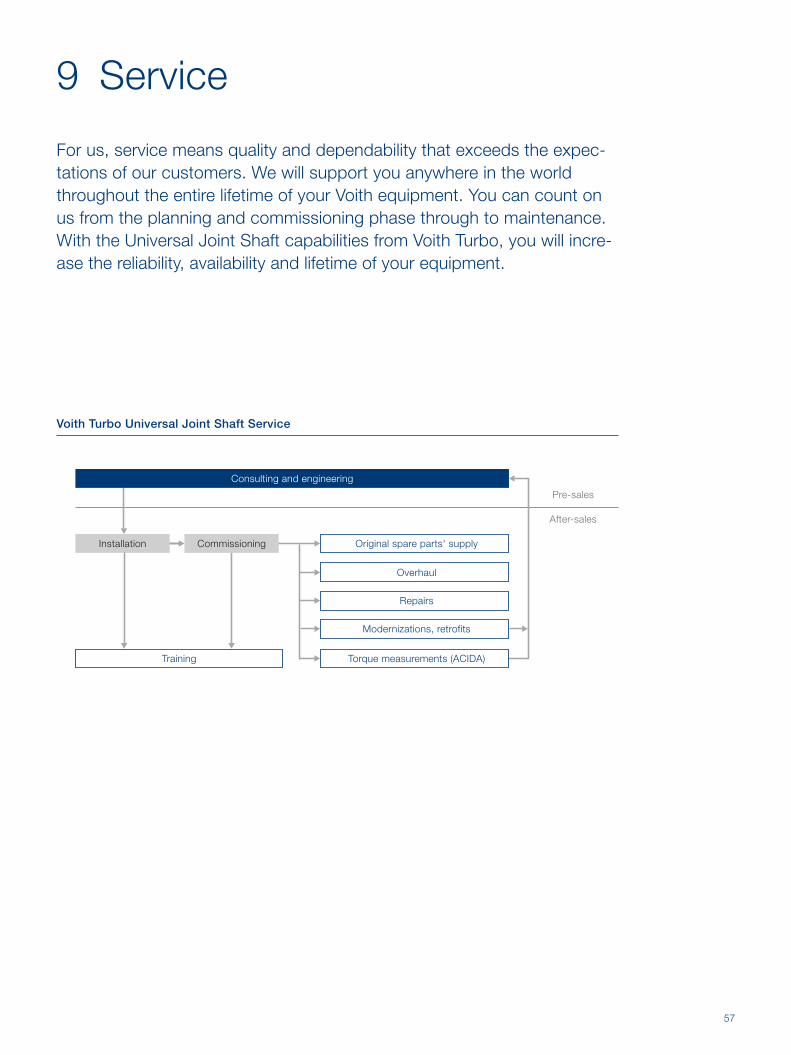
For us, service means quality and dependability that exceeds the expec-tations of our customers. We will support you anywhere in the world throughout the entire lifetime of your Voith equipment. You can count on us from the planning and commissioning phase through to maintenance. With the Universal Joint Shaft capabilities from Voith Turbo, you will incre-ase the reliability, availability and lifetime of your equipment.
Original spare parts' supply
Modernizations, retrofits
Repairs
Overhaul
Torque measurements (ACIDA)Training
Installation
Pre-sales
After-sales
Commissioning
Consulting and engineering
Voith Turbo Universal Joint Shaft Service

58
The correct installation of a universal joint shaft provides the
basis for trouble-free commissioning. A systematic com mis-
sioning procedure with extensive operational testing is an
important factor in achieving the maximum reliability and long
operational life of the universal joint shaft and the system as a
whole.
9.1 Installation and commissioning
Our services
• Installation and commissioning by our service experts
• Training of operation and maintenance personnel
Your benefits
+ Immediate access to expert know-how throughout the
start-up phase
+ Assurance of problem-free and professional
commissioning of your universal joint shaft

59
9.2 Training
Effi ciency, reliability and availability are essential factors in
ensuring your system is successful. One requirement in this
regard is having the best-trained employees in technology and
servicing. Initial and ongoing training are worthwhile in vest-
ments in ensuring the effi cient operation of your universal joint
shafts. Our training programs provide specifi c technical
knowledge about your Voith equipment, as well as other
potential products to enhance your system. We bring your
personnel up to speed with the latest Voith technology – in
theory and in practice.
Our services
• Product training at Voith or on-site at your premises
• Theoretical and practical maintenance and repair training
Your benefits
+ Safe handling of Voith products
+ Avoidance of operating and maintenance errors
+ Better understanding of Voith technology in the driveline

60
Our services
• Inventory of most original and wearing parts located
at local service branches
• Same day shipment of in-stock parts (orders received
by 11 a.m.)
• Consultation with your spare parts' management staff
• Preparation of spares kits for specifi c project maintenance
• Spares for older and obsolete series of Voith universal joint
shafts still available
Avoid risk, use Voith orginal spares and wear parts. These are
the only parts manufactured with Voith's know-how, and
guarentee the reliable and safe operation of your Voith equip-
ment. Ensuring the highest availa bility, in combination with
effi cient logistics, to ensure rapid deployment of parts globally.
Flange yokeJournal cross
9.3 Genuine Voith spare parts
Your benefits
+ Safe and reliable operation of all components
+ Parts of the highest quality that fi t precisely fi rst time
+ Maximum lifetime of driveline components
+ Manufacturer's warranty
+ Maximum system availabilty
+ Effi cient and speedy delivery of spare parts

61
Constant operation subjects universal joint shafts to natural
wear, which is also infl uenced by the surroundings. Pro-
fessional and regular overhauls of your universal joint shaft
prevent damage and minimize the risk of expensive production
downtimes. You gain operational reliability and save money in
the long term.
Our services
• Maintenance or complete overhaul by our service experts
with all the necessary tools and special fi xtures
• Use of original spare and wearing parts
• Consultation regarding your maintenance strategy
9.4 Overhaul, maintenance
Your benefits
+ Safety due to professional maintenance
+ Manufacturer's warranty
+ Increased system availability
62
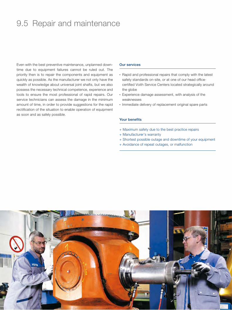
Even with the best preventive maintenance, unplanned down-
time due to equipment failures cannot be ruled out. The
priority then is to repair the components and equipment as
quickly as possible. As the manufacturer we not only have the
wealth of knowledge about universal joint shafts, but we also
possess the necessary technical competence, experience and
tools to ensure the most professional of rapid repairs. Our
service techni cians can assess the damage in the minimum
amount of time, in order to provide suggestions for the rapid
rectifi cation of the situation to enable operation of equipment
as soon and as safely possible.
9.5 Repair and maintenance
Our services
• Rapid and professional repairs that comply with the latest
safety standards on-site, or at one of our head offi ce-
certifi ed Voith Service Centers located strategically around
the globe
• Experience damage assessment, with analysis of the
weaknesses
• Immediate delivery of replacement original spare parts
Your benefits
+ Maximum safety due to the best practice repairs
+ Manufacturer's warranty
+ Shortest possible outage and downtime of your equipment
+ Avoidance of repeat outages, or malfunction

63
9.6 Retrofit and modernizations
Technology is advancing all the time and sometimes the
original require ments upon which the design of a system was
based can change. Voith Turbo helps you achieve signifi cant
improvements in the effi ciency and reliability of your equip-
ment, through a modernization or retrofi t program of old
driveline equipment, e.g. slipper spindles. We will analyze, and
provide advise as to the latest and most economical tech-
nology for your particular driveline application.
Our services
• Modernization of existing, or new replacement designs for
your universal joint shafts and connection components
• Even with the best preventative maintenance schedule,
unplanned downtime due to equipment failure can never
be ruled out
Your benefits
+ Improved reliability, availability and affordability of your
driveline
+ Reduction of operating costs
+ Universal joint shafts that feature the latest technology
64
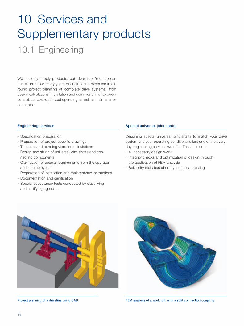
Project planning of a driveline using CAD FEM analysis of a work roll, with a split connection coupling
10 Services and Supplementary products 10.1 Engineering
We not only supply products, but ideas too! You too can benefi t from our many years of engineering expertise in all-round project planning of complete drive systems: from design calculations, installation and commissioning, to ques-tions about cost-optimized operating as well as main ten ance concepts.
Engineering services
• Specifi cation preparation• Preparation of project-specifi c drawings• Torsional and bending vibration calculations• Design and sizing of universal joint shafts and con-
necting components• Clarifi cation of special requirements from the operator
and its employees• Preparation of installation and maintenance instructions• Documentation and certifi cation• Special acceptance tests conducted by classifying
and certifying agencies
Special universal joint shafts
Designing special universal joint shafts to match your drive system and your operating conditions is just one of the every-day engineering services we offer. These include:• All necessary design work• Integrity checks and optimization of design through
the application of FEM analysis• Reliability trials based on dynamic load testing

65
Connection hubs (wobblers/couplings) to attach universal joint shafts to the work rolls
10.2 Connecting components for universal joint shafts
To ensure maximum reliability of the driveline, the input and output connecting parts of the universal joint shaft, should equally be analyzed for suitability, e.g.:• All couplings• All connecting fl anges bolted or otherwise• All Adapters
Features
• Individual adaptation to all adjoining components• Precision manufacturing through the use of state-of-the-art
machining centers• Maximum torque transmission capability through the use of
the highest quality materials.• Hardened contact surfaces to ensure maximim levels of
wear resistance.
Applications
• Rolling mills• Paper machinery• Pumps• General industrial machinery• Test stands• Construction equipment and cranes
66
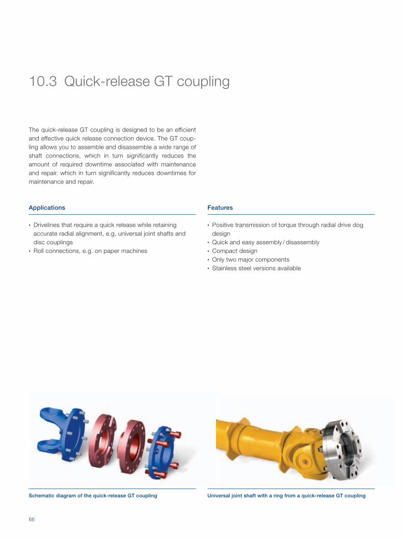
Schematic diagram of the quick-release GT coupling Universal joint shaft with a ring from a quick-release GT coupling
10.3 Quick-release GT coupling
The quick-release GT coupling is designed to be an efficient and effective quick release connection device. The GT coup-ling allows you to assemble and disassemble a wide range of shaft connections, which in turn significantly reduces the amount of required downtime associated with maintenance and repair. which in turn significantly reduces downtimes for maintenance and repair.
Features
• Positive transmission of torque through radial drive dog design
• Quick and easy assembly / disassembly• Compact design• Only two major components• Stainless steel versions available
Applications
• Drivelines that require a quick release while retaining accurate radial alignment, e.g. universal joint shafts and disc couplings
• Roll connections, e.g. on paper machines

67
Universal joint shaft flanges with Hirth coupling
Positive locking Accurate indexing Self-centering
Primary functions of the Hirth serration
10.4 Voith Hirth couplings
Voith Hirth couplings transmit maximum torque at the speci-fied diameters.
Features
• Highest torque transmission capability, as the angular
surfaces provide positive locking of most of the peripheral
forces. The bolts only need to accomodate a small amount
of axial force.
• Self-centering by means of optimized tooth geometry
• A high load bearing on the tooth profi le, signifi cantly
inreases wear resistance of the hirth serration.
• Repeatability accuracy maximized as a result of the
multiple tooth design.
Fa
Fu
Applications
• High performance universal joint shafts, for high torque
applications
• Connection fl ange for universal joint shafts (also when
provided by the customer)
• Machine tools
• Turbo compressors
• Measuring equipment
• Robotic equipment
• Nuclear technology
• Medical equipment
• General industrial machinery

68
Universal joint shaft support (red) and coupling support (yellow)
10.5 Universal joint shaft supports
To position and support a universal joint shaft and its connec-tion coupling and flanges, a support mechanism is required.
Features
• Increased productivity and system availability as a result
of shorter downtime for maintenance
• Reduction of energy and lubrication costs, together with
higher transmission effi ciency through the use of roller
bearings
• Reduced wear as a result of uniform power transmission
Applications
• Rolling mills
• Customer-specifi c drives

69
Universal joint shaft with CFRP tube
10.6 Universal joint shafts with carbon fiber-reinforced polymer (CFRP) components
Universal joint shafts with CFRP components increase the efficiency and performance of machines and plants. CFRP use in universal joint shaft construction, reduces masses, vibrations, deformations and power consuption of the ma-chines. We offer not only the characteristic know-how, but also the production know-how of CFRP components – all from a single source.
Features
• Depending on the requirements of the specifi c application,
universal joint shafts can incorporate CFRP tube, or solid
shafts
• Reduced dynamic loads, due to lower masses
• Extremely smooth operation and low vibration induced
wear, as a result of the higher rigidity of CFRP
• Lower acceleration / deceleration torques as a result of the
lower mass of intertia of CFRP
Applications
• Long drivelines without the need for intermediate bearing
supports
• Drivelines with low masses
• Drivelines that require optimized vibration behaviour
• Pumps
• Marine vessels
• Rail vehicles
• General industrial machinery

70
10.7 High-performance lubricant for universal joint shafts
Voith development engineers have combined their universal
joint shaft know-how with the tribological knowledge and
experience of renowned bearing and lubricant manufacturers.
The result of this cooperation is an innovative and exclusive
lubricant with properties that far exceed those of conventional
lubricants. This lubricant gives bearings in universal joint shafts
operating at low speeds and under high loads an even longer
life. In addition, lubrication intervals can be extended and
emergency dry-running characteristics are improved sig nifi -
cantly.
1 Voith WearCare 500 in 45 kg and 180 kg drums
1

71
Characteristics of the Voith WearCare 500 high-performance lubricant
Advantages
• Optimum adhesion and surface wetting + Lubricating fi lm even in the event of poor lubrication
+ Formulated for oscillating bearing motion
• Exceptional corrosion protection + Ideal for rolling mills
• Maximum ability to withstand pressure + Hydrodynamic lubricating fi lm even under maximum torque
conditions
• Optimal and long-lasting lubricating action + Minimal abrasive wear in the bearing
+ Extended lubrication intervals
+ Reduced maintenance costs
• Can be mixed with lithium-based greases + Simple changeover to Voith's high-performance lubricant
• High resistance to aging + Long shelf life
• Excellent compatibility with all bearing components + No softening of bearing seals
+ Does not corrode non-ferrous metals
• Free of silicone and copper-based ingredients + Suitable for aluminum rolling mills
Rela
tive m
eta
l p
art
icle
s in
th
e lu
brican
t
1
0 3 6 9 15 18 21 24
Operating time in months
12
1.5
0.5
Extended
operating time
Reference
wear condition
Field trial
Metal particles in the bearing lubricant of a high-performance
universal joint shaft used in a rolling mill drive
FE8 test stand trial
Bearing wear in an axial cylindrical roller bearing
Rela
tive b
earin
g w
ear
1
10
Voith
WearCare
500
5
15Standard
lubricant
Standard lubricant
Voith
WearCare 500

72
3D cut away section through a Safeset safety coupling (type SR-C) Safeset torque limiting safety couplings (blue) 'integral design' in a Voith high performance universal joint shaft
10.8 Safeset torque-limiting safety couplings
The Safeset coupling is a torque-limiting safety coupling that instantaneously disengages the power transmission of the driveline in the event of a potentially catastrophic torque over-load event. Thus it protects all of the drive components in the driveline such as motors, gearboxes, universal joint shafts etc. against costly and time consuming damage.
By integrating the Safeset safety coupling into the universal joint shaft, which is known as the Voith 'integral design', reduces the deflection angle of the universal joints, and thus increases the lifetime of driveline components.
Features
• Adjustable release torque
• The Safeset coupling reacts instantaneously to a torque
overload event
• Backlash-free power transmission
• Compact, lightweight design
• Low mass moment of inertia
• Minimal maintenance required
Applications
• Protects drivelines from potentially catastrophic overload
damage
• Rolling mills
• Shredders
• Cement mills
• Sugar mills
• Rail vehicle drives

73
Torq
ue [N
m]
Time [s]
62.84 63.90 64.95 66.00 67.06 68.11 69.16 70.22-46
103
253
401
550
10.9 ACIDA torque monitoring systems
1 Rotor: Strain gauges and telemetry (requires no drive modifi cations)
2 Air gap: No contact between rotor and stator
3 Stator: Signal reception and inductive power supply
Light blue: ACIDA monitoring systems measure torques and dynamics with extreme accuracy.
Dark blue: Conventional systems measure, for example, the motor current or hydraulic pressure with insuffi cient signal dynamics.
ACIDA torque monitoring systems have proven their worth in accurately measuring dynamics in universal joint shafts.
The direct measuring of the actual, mechanical drive load provides important information for process observation and plant optimization. Analysis modules, for instance load spectra or lifetime observation, have been developed especially for extremely heavy-duty drives and unusually severe load condi-tions. Additional options include online vibration diagnosis for gearboxes and roller bearings.
Features
• Permanent or temporary torque sensors• Complete monitoring systems, incl. hardware and software• Report generator with automatic analysis, alarm signaling
and reporting• Tele-service with expert support
The ACIDA monitoring system in comparisonNon-contact torque monitoring system
Applications
• Torque monitoring• Vibration monitoring• Process optimization• Condition-based maintenance• Reference systems: Rolling mills, cement mills, briquetting
plants, agitators, conveying equipment, marine propulsion systems, locomotives, paper machines, mining, etc.
1
23

74
11 Integrated management system
At Voith, our top priority is to ensure the affordability, reliability, environ-mental compatibility and safety of our products and services. In order to maintain these principles in the future just as we do today, Voith Turbo has a firmly established integrated management system focused on quality, the environment, and health and safety at work. For our customers, this means that they are purchasing high-quality capital goods that are manufactured and can be used in safe surroundings and with minimal environmental impact.
1

75
2
11.1 Quality
1 Certifi cates for management systems according to ISO 9 001: 2 000 (Quality), ISO 14 001: 2 000 (Environment) and OHSAS 18 001: 1 999 (Occupational Health and Safety)
2 Flange for a high-performance universal joint shaft on a 3-D-coordinate measuring machine
• We employ state-of-the-art 3-D-coordinate measuring machines for quality assurance.
• To ensure perfectly welded joints, we conduct X-ray inspections in-house.
• We offer our customers a variety of product and application-specific certifications and classifications.
• Production and assembly fixtures are inspected on a regular basis.
• Quality-relevant measuring and testing instruments are subject to systematic monitoring.
• In the case of the welding methods employed, process controls according to ISO 3834-2 are used. Welding technicians are qualified to EN287 and our welding equipment is constantly monitored.
• Employees performing non-destructive testing are qualified to ASNT-C-1A and / or EN 473.

76
11.2 Environment
• Voith universal joint shafts are fitted with sealed roller bea rings. These offer two major advantages over slipper and gear type spindles:
1
1. Lubricant consumption is considerably lower because of the seals.
2. Efficiency is enhanced, as rolling friction is significantly less than sliding friction. This translates into reduced CO2-emissions and helps to protect the environment.
0.32 kW99.10 %
71.1 kW
Slipper spindle
99.49 %41.1 kW
Gear spindleVoith universal joint shaft
99.996 %
Comparison of efficiency and power loss in the main drive of a rolling mill
Input power 8 000 kW,
deflection angle 2°
Efficiency Power loss

77
1 An employee coats the roller bearing of a universal joint shaft with Voith WearCare 500 high-performance lubricant
2 Voith universal joint shafts receive their fi nal fi nish in a modern paint booth
11.3 Occupational health and safety
• When painting a Voith universal joint shaft, Voith paint tech nicians use a modern paint system that meets all of the requirements for health and safety at work, and envi-ronmetal protection.
• The paint is electrostatically applied to reduce overspray and waste.
• An exhaust system extracts any residual mist that is created as part of the paint process.
• An exhaust air treatment system with combined heat reco-very reduces the impact on our employees, as well as the environment.
2

Voith Turbo GmbH & Co. KGUniversal Joint Shafts and Hirth CouplingsAlexanderstr. 289522 Heidenheim, GermanyTel. +49 7321 37-8283Fax +49 7321 [email protected]
www.voithturbo.com/universal-joint-shafts
G8
30
en
, S
&F
-nlg
/ C
M,
04
.20
12
, 1
00
0.
Dim
ensi
ons
and
illu
stra
tions
with
out
oblig
atio
n. S
ubje
ct t
o m
odifi
catio
ns.