high-power 3,500 ball screw jack owner’s …high power 3,500 ball screw jack owner’s...
TRANSCRIPT
(+)30 AMP
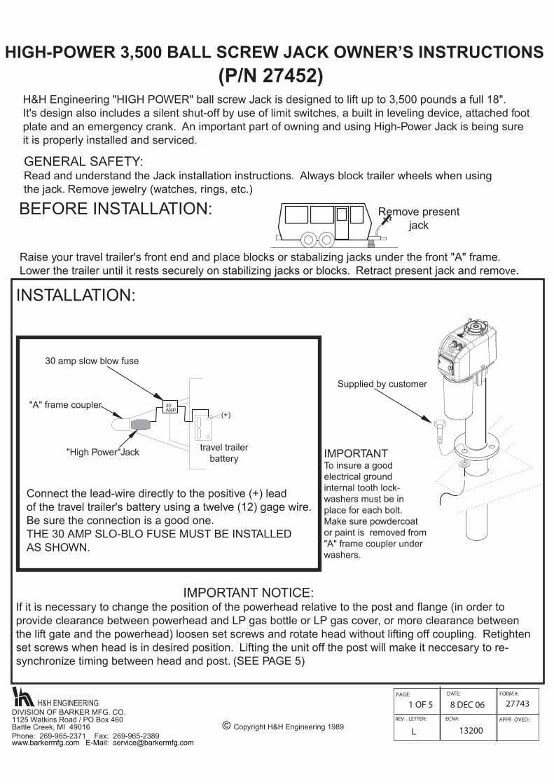
HIGH-POWER 3,500 BALL SCREW JACK OWNER’S INSTRUCTIONS (P/N 27452)
GENERAL SAFETY:Read and understand the Jack installation instructions. Always block trailer wheels when using the jack. Remove jewelry (watches, rings, etc.)
30 amp slow blow fuse
"High Power"Jack travel trailerbattery
Connect the lead-wire directly to the positive (+) leadof the travel trailer's battery using a twelve (12) gage wire. Be sure the connection is a good one. THE 30 AMP SLO-BLO FUSE MUST BE INSTALLEDAS SHOWN.
INSTALLATION:
IMPORTANT NOTICE:If it is necessary to change the position of the powerhead relative to the post and flange (in order to provide clearance between powerhead and LP gas bottle or LP gas cover, or more clearance betweenthe lift gate and the powerhead) loosen set screws and rotate head without lifting off coupling. Retightenset screws when head is in desired position. Lifting the unit off the post will make it neccesary to re-synchronize timing between head and post. (SEE PAGE 5)
PAGE: DATE: FORM #:
REV . LETTER: ECN#: APPR OVED:
1 OF 5 8 DEC 06 27743
L 13200
BEFORE INSTALLATION:
Raise your travel trailer's front end and place blocks or stabalizing jacks under the front "A" frame. Lower the trailer until it rests securely on stabilizing jacks or blocks. Retract present jack and remove.
H&H Engineering "HIGH POWER" ball screw Jack is designed to lift up to 3,500 pounds a full 18". It's design also includes a silent shut-off by use of limit switches, a built in leveling device, attached footplate and an emergency crank. An important part of owning and using High-Power Jack is being sureit is properly installed and serviced.
Remove presentjack
"A" frame coupler
IMPORTANTTo insure a goodelectrical ground internal tooth lock-washers must be in place for each bolt. Make sure powdercoator paint is removed from"A" frame coupler underwashers.
Supplied by customer
© Copyright H&H Engineering 1989
LIGHT ON
POWERSERIES 3500
High
H&H ENGINEERINGDIVISION OF BARKER MFG. CO.1125 Watkins Road / PO Box 460 Battle Creek, MI 49016Phone: 269-965-2371 Fax: 269-965-2389www.barkermfg.com E-Mail: [email protected]
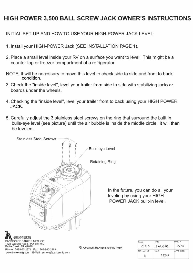
INITIAL SET-UP AND HOW TO USE YOUR HIGH-POWER JACK LEVEL:
1. Install your HIGH-POWER Jack (SEE INSTALLATION PAGE 1).
2. Place a small level inside your RV on a surface you want to level. This might be acounter top or freezer compartment of a refrigerator.
NOTE: It will be necessary to move this level to check side to side and front to back 3. Check the "inside level", level your trailer from side to side with stabilizing jacks or
boards under the wheels.
4. Checking the "inside level", level your trailer front to back using your HIGH POWER
5. Carefully adjust the 3 stainless steel screws on the ring that surround the built inbulls-eye level (see picture) until the air bubble is inside the middle circle,be leveled.
Bulls-eye Level
Retaining Ring
Stainless Steel Screws
In the future, you can do all your leveling by using your HIGH POWER JACK built-in level.
H&H ENGINEERINGDIVISION OF BARKER MFG. CO.1125 Watkins Road / PO Box 460Battle Creek, MI 49016Phone: 269-965-2371 Fax: 269-965-2389
© Copyright H&H Engineering 1989
PAGE: DATE: FORM #:
REV . LETTER: ECN#: APPR OVED:
2 OF 5 8 A UG 06 27743
K 13247
HIGH POWER 3,500 BALL SCREW J ACK OWNER’S INSTRUCTIONS
LIGHT ON
POWERSERIES 3500
High
condition.
it will then
JACK.
www.barkermfg.com E-Mail: [email protected]
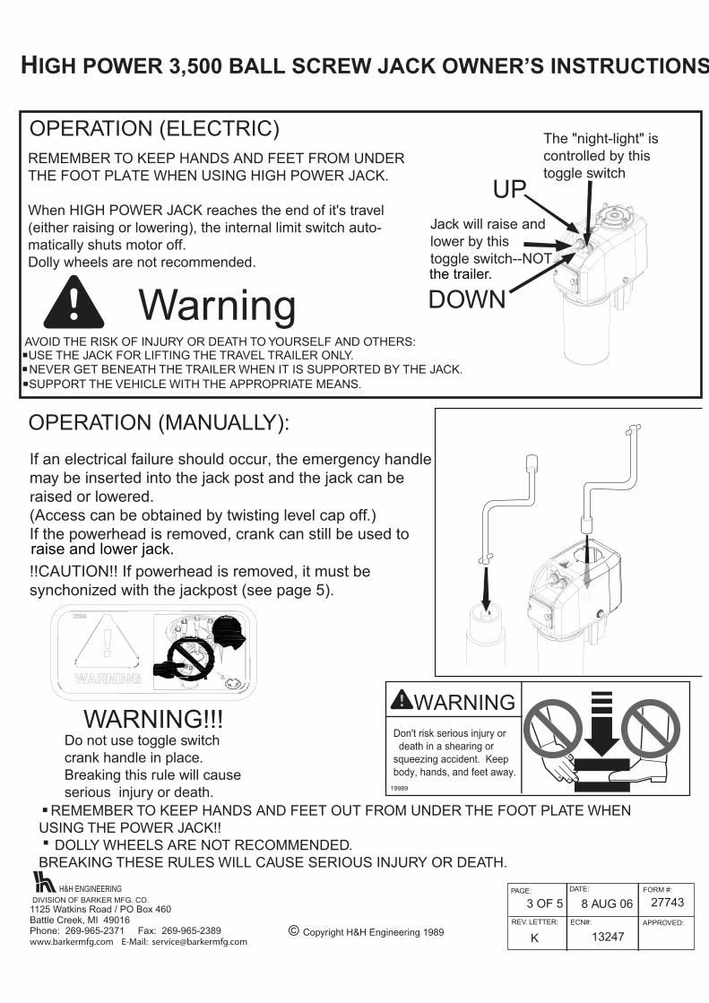
OPERATION (ELECTRIC)REMEMBER TO KEEP HANDS AND FEET FROM UNDERTHE FOOT PLATE WHEN USING HIGH POWER JACK.
When HIGH POWER JACK reaches the end of it's travel(either raising or lowering), the internal limit switch auto-matically shuts motor off.Dolly wheels are not recommended.
WarningAVOID THE RISK OF INJURY OR DEATH TO YOURSELF AND OTHERS:USE THE JACK FOR LIFTING THE TRAVEL TRAILER ONLY..NEVER GET BENEATH THE TRAILER WHEN IT IS SUPPORTED BY THE JACK..SUPPORT THE VEHICLE WITH THE APPROPRIATE MEANS.
.
Jack will raise andlower by thistoggle switch--NOT.
OPERATION (MANUALLY):
H&H ENGINEERINGDIVISION OF BARKER MFG. CO.
PAGE: DATE: FORM #:
REV. LETTER: ECN#: APPROVED:
3 OF 5 8 AUG 06 27743
K 13247© Copyright H&H Engineering 1989
WARNING!!! Do not use toggle switchcrank handle in place.Breaking this rule will cause serious injury or death.
REMEMBER TO KEEP HANDS AND FEET OUT FROM UNDER THE FOOT PLATE WHEN USING THE POWER JACK!! DOLLY WHEELS ARE NOT RECOMMENDED.BREAKING THESE RULES WILL CAUSE SERIOUS INJURY OR DEATH.
The "night-light" iscontrolled by this toggle switch
UP
DOWN
WARNING
19989
Don't risk serious injury or death in a shearing or squeezing accident. Keep body, hands, and feet away.
HIGH POWER 3,500 BALL SCREW JACK OWNER’S INSTRUCTIONS
If an electrical failure should occur, the emergency handlemay be inserted into the jack post and the jack can beraised or lowered.(Access can be obtained by twisting level cap off.)If the powerhead is removed, cr ank can still be used to
!!CAUTION!! If powerhead is removed, it must be synchonized with the jackpost (see page 5).
.
.
LIGHT ON
LIGHT ON
the trailer.
1125 Watkins Road / PO Box 460Battle Creek, MI 49016Phone: 269-965-2371 Fax: 269-965-2389www.barkermfg.com E-Mail: [email protected]
raise and lower jack.
PAGE: DATE: FORM #:
REVISION LETTER: ECN#: APPROVED:
4 OF 5 7 JUL 10 27743
O 14239© Copyright H&H Engineering 1989
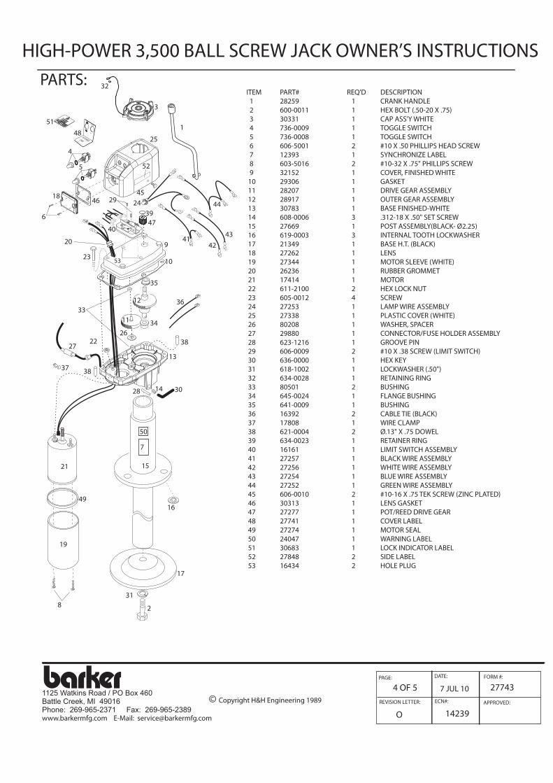
HIGH-POWER 3,500 BALL SCREW JACK OWNER’S INSTRUCTIONS PARTS:
ITEM PART# REQ'D DESCRIPTION 1 28259 1 CRANK HANDLE 2 600-0011 1 HEX BOLT (.50-20 X .75) 3 30331 1 CAP ASS'Y WHITE 4 736-0009 1 TOGGLE SWITCH 5 736-0008 1 TOGGLE SWITCH 6 606-5001 2 #10 X .50 PHILLIPS HEAD SCREW 7 12393 1 SYNCHRONIZE LABEL 8 603-5016 2 #10-32 X .75" PHILLIPS SCREW 9 32152 1 COVER, FINISHED WHITE 10 29306 1 GASKET 11 28207 1 DRIVE GEAR ASSEMBLY 12 28917 1 OUTER GEAR ASSEMBLY 13 30783 1 BASE FINISHED-WHITE 14 608-0006 3 .312-18 X .50" SET SCREW 15 27669 1 POST ASSEMBLY(BLACK- Ø2.25) 16 619-0003 3 INTERNAL TOOTH LOCKWASHER 17 21349 1 BASE H.T. (BLACK) 18 27262 1 LENS 19 27344 1 MOTOR SLEEVE (WHITE) 20 26236 1 RUBBER GROMMET 21 17414 1 MOTOR 22 611-2100 2 HEX LOCK NUT 23 605-0012 4 SCREW 24 27253 1 LAMP WIRE ASSEMBLY 25 27338 1 PLASTIC COVER (WHITE) 26 80208 1 WASHER, SPACER 27 29880 1 CONNECTOR/FUSE HOLDER ASSEMBLY 28 623-1216 1 GROOVE PIN 29 606-0009 2 #10 X .38 SCREW (LIMIT SWITCH) 30 636-0000 1 HEX KEY 31 618-1002 1 LOCKWASHER (.50") 32 634-0028 1 RETAINING RING 33 80501 2 BUSHING 34 645-0024 1 FLANGE BUSHING 35 641-0009 1 BUSHING 36 16392 2 CABLE TIE (BLACK) 37 17808 1 WIRE CLAMP 38 621-0004 2 Ø.13" X .75 DOWEL 39 634-0023 1 RETAINER RING 40 16161 1 LIMIT SWITCH ASSEMBLY 41 27257 1 BLACK WIRE ASSEMBLY 42 27256 1 WHITE WIRE ASSEMBLY 43 27254 1 BLUE WIRE ASSEMBLY 44 27252 1 GREEN WIRE ASSEMBLY 45 606-0010 2 #10-16 X .75 TEK SCREW (ZINC PLATED) 46 30313 1 LENS GASKET 47 27277 1 POT/REED DRIVE GEAR 48 27741 1 COVER LABEL 49 27274 1 MOTOR SEAL 50 24047 1 WARNING LABEL 51 30683 1 LOCK INDICATOR LABEL 52 27848 2 SIDE LABEL 53 16434 2 HOLE PLUG
HI POWER 3500
OFF
LIGHT ON
B A R K E R M F G . B A T T L E C R E E K
1
2
5
6
9
10
11
12
13
14
15
50
7
16
17
318
19
21
49
3028
382722
35
33
26
23
29
4739
40
20 41
24
43
4418
46
4825
45
53
37 38
42
34
51
4
32
3
36
52
1125 Watkins Road / PO Box 460Battle Creek, MI 49016Phone: 269-965-2371 Fax: 269-965-2389www.barkermfg.com E-Mail: [email protected]

MAINTENANCE: Once a year, the powerhead should be removed and a liberal amount of grease (preferably a grease with high melting point) applied directly to the coupling on which the drive pin rests.DO NOT POUR OIL into top of the jack post.
Once a year, the housing cover should be removed and the gears inspected for proper lubrication. Remove 4 screws and tap around edge of housing to free cover. DO NOT insert screw driver blade!(This may damage mating surfaces.) Before replacing cover, clean mating surfaces. If lubrication is needed, use Lubriplate GR-132 grease or equivalent.
H&H ENGINEERINGDIVISION OF BARKER MFG. CO.1125 Watkins Road / PO Box 460 Battle Creek, MI 49016Phone: 269-965-2371 Fax: 269-965-2389
PAGE: DATE: FORM #:
REVISION LETTER: ECN#: APPR OVED:
5 OF 5 8 A UG 06 27743
K 13247© Copyright H&H Engineering 1989
SCHEMATIC WIRING DIAGRAMSTRAP ATTACHMENT
1. Press strap (1) onto the stud (2) atthe bottom of the cap.2. Press the retaining ring (3) on stud(2) snug it down against the strap (1).3. Repeat this process (4) on the studfound on the inside of the cover.
2
3 14
COVER,INSIDE
BOTTOM OF CAP
HIGH-POWER 3,500 BALL SCREW JACK OWNER'S INSTRUCTIONS
THIS WILL SECURE YOUR CAP
SYNCHRONIZATION INSTRUCTIONS:Powerhead must be synchronized with the jack post:1. Use the crank to fully retract post.2. Crank jackpost one turn in opposite direction.3. ground powerhead to jackpost or trailer frame.4. Toggle switch down as if lowering the trailer or retracting the post. Continueto hold switch down until motor stops running (as if jackpost is retracted all the way).5. Install powerhead and tighten (3)set screws.
www.barkermfg.com E-Mail: [email protected]