high-power, high-energy diode-pumped tm:ylf-ho:ylf laser 2003 tm-ho_0.pdf · high-power,...
TRANSCRIPT
High-power, high-energy diode-pumped
Tm:YLF-Ho:YLF laser
Alex Dergachev, and Peter F. Moulton
Q-Peak, Inc.
135 South Road, Bedford, Massachusetts 01730Tel.: (781) 275-9535, FAX: (781) 275-9726
E-mail: [email protected]
Acknowledgements:Lockheed MartinLaser Ultrasonic Technology Center
• Motivation• Previous Results• Tm:YLF Laser - Details• Ho:YLF Laser – Details• ZGP OPO• Conclusions
Outline

Motivation
Development of a 2-um laser source:• High-energy (up to 100 mJ)• High repetition rate (100-400 Hz) • High beam quality (TEMoo)
ZGPOPO
Ho:YLFlaser
Tm:YLFlaser
30 mJ3200 nm
100 mJ2050 nm
100 Hz - 400 Hz
CW1940 nm
Possible applications :• Pump source for other IR lasers • Industrial• Military
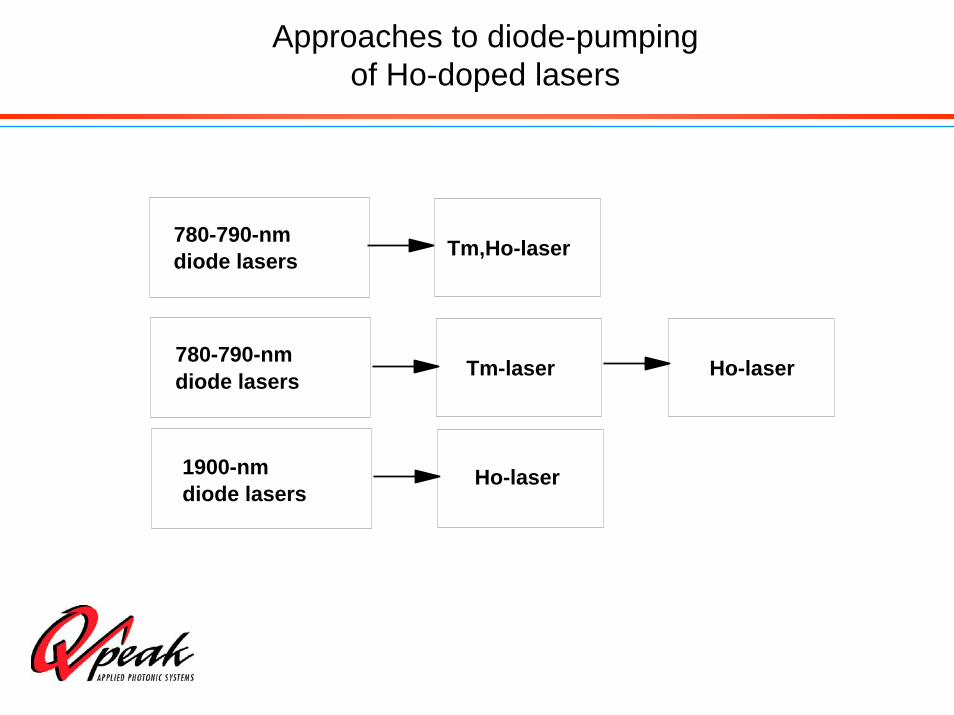
Approaches to diode-pumpingof Ho-doped lasers
780-790-nmdiode lasers Tm,Ho-laser
780-790-nm Tm-laser
1900-nm Ho-laser
Ho-laserdiode lasers
diode lasers

Advantages of Tm-pumped Ho-laser
• Compared to diode-pumped Tm, Ho-co-doped laser:
– Eliminates upconversion from Tm-Ho interaction that reduces efficiency and creates additional heating in crystal
– Eliminates energy sharing between Tm and Ho that limits energy extraction in Q-switched mode
• Compared to direct-diode-pumped Ho-laser
– Can operate at much higher power due to the availability of high-power diodes for Tm:YLF pumping

References on resonantly pumped Ho lasers
P.F. Moulton, “Industry R&D related to 2-μm lidars,” Second Review of 2-μm Solid State Laser Technology, NASA Headquarters, Washington, DC, May 18-19, 1992.
R.C. Stoneman and L. Esterowitz, Opt. Lett. 17, 736 (1992).
D.W Hart, M. Jani and N.P. Barnes, Opt. Lett. 21, 728 (1996).
M. Petros, J. Yu, U. N. Singh and N.P. Barnes, “High energy directly pumped Ho:YLF laser,” in Advanced Solid State Lasers, OSA Technical Digest (Optical Society of America, Washington, DC, 2000), pp. 79-81.
P.A. Budni, M.L. Lemons, J.R. Mosto, and E.P. Chicklis, IEEE J. Sel. Topics in Quantum Electron. 6, 629 (2000).
P.A. Budni, M.L. Lemons, C.A. Miller, P.A. Ketteridge, L.A. Pomeranz, T.M. Pollak, P.G.Schuneman, K.L. Lanier, J.R. Mosto, and E.P. Chicklis, “High power 1.9 micron pumped solid state holmium lasers,” in Conference on Lasers and Electro-Optics, OSA Technical Digest (Optical Society of America, Washington, DC, 2000), p 564.
L.D. DeLoach, S.A. Payne, L.L. Chase, L.K. Smith, W.L. Kway and W.F. Krupke, IEEE J. Quantum Electron. 29, 1179 (1993).
W.F. Krupke and L.L. Chase, Optical and Quantum Electron. 22, S1 (1989).

Previous results – Ho-lasers
Tm:YLF pumped Ho:YAGP. A. Budni et al., “High-power/high-brightness diode-pumped 1.9-µm Thulium and resonantly pumped 2.1-µm Holmium lasers,” IEEE J. on Selected Topics in Quantum Electron., 6, 629-635 (2000).
• Tm:YLF pump– 36 W CW output at 1.907 mm (σ-line)– Multimode, M2 ~ 2
• Ho:YAG– CW: 19 W– QCW: 16 W at 15 kHz

Ho:YLF vs Ho:YAG
Why Ho:YLF?• Long upper laser level lifetime ~ 15 ms• Higher emission cross-section• Naturally birefringent material• Low dn/dT –> weak thermal lensing
Ho:YAG•Isotropic
•Lifetime (5I7) 7 ms
•Strong thermal lensing
•Excellent thermo-mechanical properties

Gain Calculation – 3.5% Tm:YLF
-0.25
-0.20
-0.15
-0.10
-0.05
0.00
0.05
0.10
0.15
0.20
0.25
1800 1825 1850 1875 1900 1925 1950 1975 2000
Wavelength, nm
Gai
n co
effic
ient
, cm
-1
0.25, π
0.25, σ
0.15, π
0.15, σ
Inversion fraction
Polarized gain in Tm:YLF at two values of inversion fractiong(λ) = N [ p⋅σem(λ) - (1-p)⋅σabs(λ) ],where p – inversion fraction, N - Tm-concentration
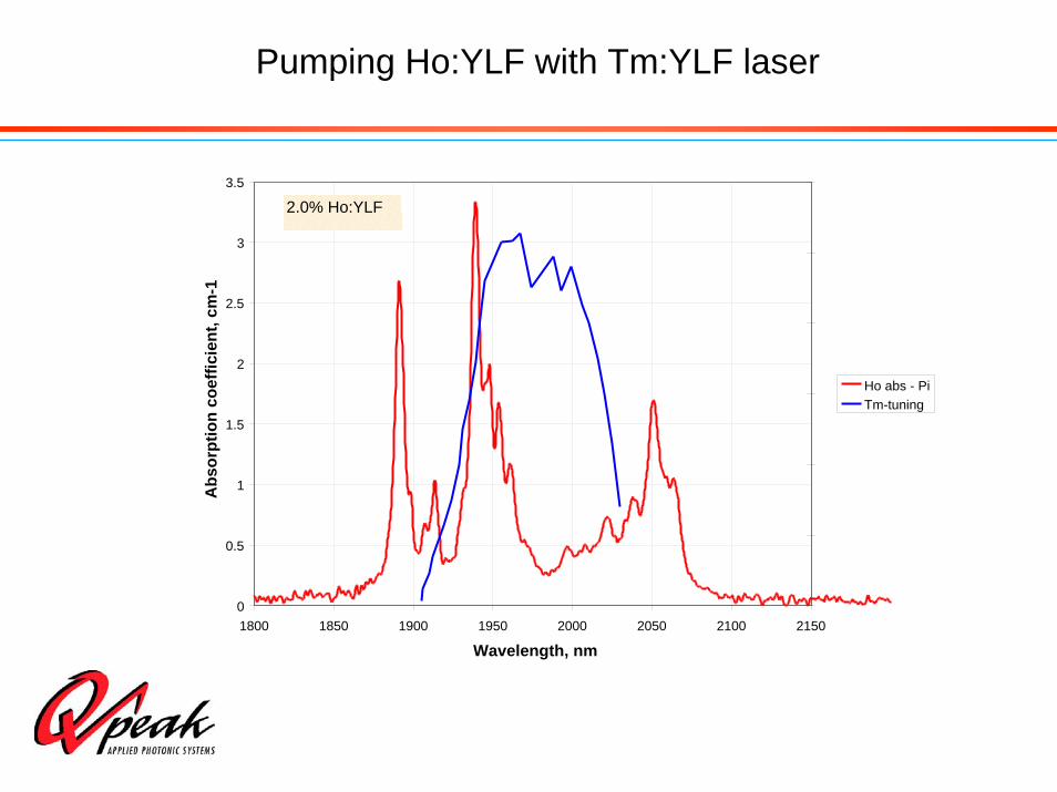
Pumping Ho:YLF with Tm:YLF laser
0
0.5
1
1.5
2
2.5
3
3.5
1800 1850 1900 1950 2000 2050 2100 2150
Wavelength, nm
Abs
orpt
ion
coef
ficie
nt, c
m-1
Ho abs - PiTm-tuning
2.0% Ho:YLF

Tm:YLF Active Element:Rectangular slab: 22-mm longClear aperture 2x6 mm.
Experimental Set-Up – Tm:YLF Laser
Tm:YLF DL
HR
OC
DL
BRF
Tm:YLF DL
DL
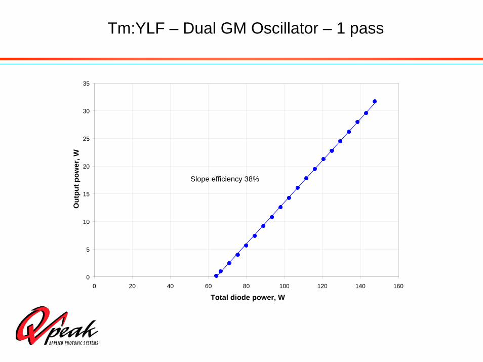
Tm:YLF – Dual GM Oscillator – 1 pass
0
5
10
15
20
25
30
35
0 20 40 60 80 100 120 140 160
Total diode power, W
Out
put p
ower
, W
Slope efficiency 38%
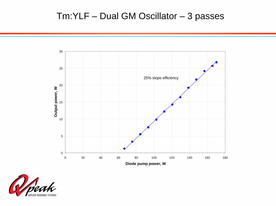
Tm:YLF – Dual GM Oscillator – 3 passes
0
5
10
15
20
25
30
0 20 40 60 80 100 120 140 160 180
Diode pump power, W
Out
put p
ower
, W
25% slope efficiency
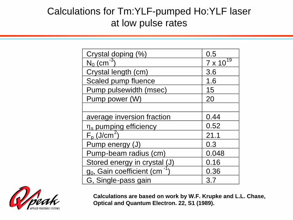
Calculations for Tm:YLF-pumped Ho:YLF laser at low pulse rates
Calculations are based on work by W.F. Krupke and L.L. Chase, Optical and Quantum Electron. 22, S1 (1989).
Crystal doping (%) 0.5N0 (cm-3) 7 x 10¹⁹
Crystal length (cm) 3.6Scaled pump fluence 1.6Pump pulsewidth (msec) 15Pump power (W) 20
average inversion fraction 0.44ηs pumping efficiency 0.52Fp (J/cm2) 21.1Pump energy (J) 0.3Pump-beam radius (cm) 0.048Stored energy in crystal (J) 0.16g0, Gain coefficient (cm -1) 0.36G, Single-pass gain 3.7

Schematic layout of the end-pumped Ho:YLF laser
HR
OC
AOM
Ho:YLF
Tm:YLF laser #1
Tm:YLF laser #2
DM
DM
DM – Dichroic Mirror, AOM – Acousto-Optic Modulator, OC – Output Coupler, HR – High Reflector

CW Ho:YLF Laser Operation (TEMoo)
0
5
10
15
20
25
0 10 20 30 40 50 60
Total Tm pump power, W
Ho:
YLF
CW
out
put,
W
10%15%40%70%
54% slope efficiency
45% slope efficiency
Toc

Ho:YLF – Q-Switched Operation (TEMoo)
0
2
4
6
8
10
12
14
16
18
0 500 1000 1500 2000 2500
Repetition rate, Hz
Out
put p
ower
, W
0
5
10
15
20
25
30
35
40
Puls
e en
ergy
, mJ
PE

Ho:YLF – Pulsewidth vs repetition rate
0
5
10
15
20
25
0 200 400 600 800 1000 1200
Repetition rate, Hz
Puls
ewid
th, n
s
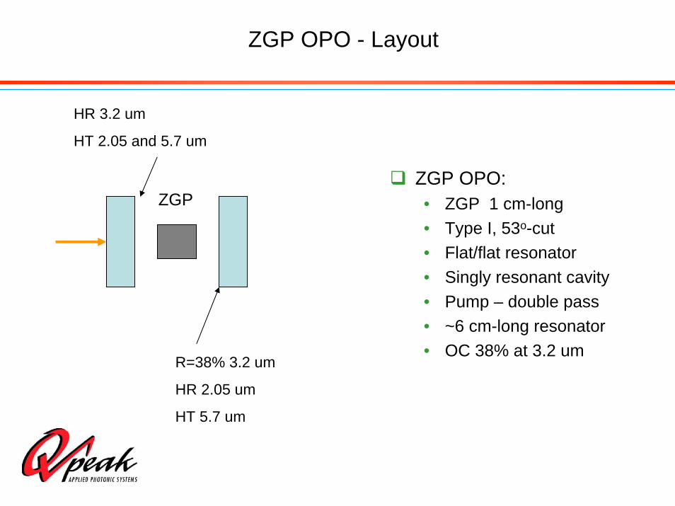
ZGP OPO - Layout
ZGP OPO:• ZGP 1 cm-long• Type I, 53o-cut • Flat/flat resonator• Singly resonant cavity• Pump – double pass• ~6 cm-long resonator• OC 38% at 3.2 um
R=38% 3.2 um
HR 2.05 um
HT 5.7 um
HR 3.2 um
HT 2.05 and 5.7 um
ZGP

ZGP Operation – 400 Hz
0
0.5
1
1.5
2
2.5
3
3.5
4
4.5
0 1 2 3 4 5 6 7 8 9 10
Pump power, W
OPO
out
put,
W
0.00
0.05
0.10
0.15
0.20
0.25
0.30
0.35
0.40
0.45
0.50
Con
vers
ion
effic
ienc
y
PoutEff.
Slope Efficiency 63%
400 Hz
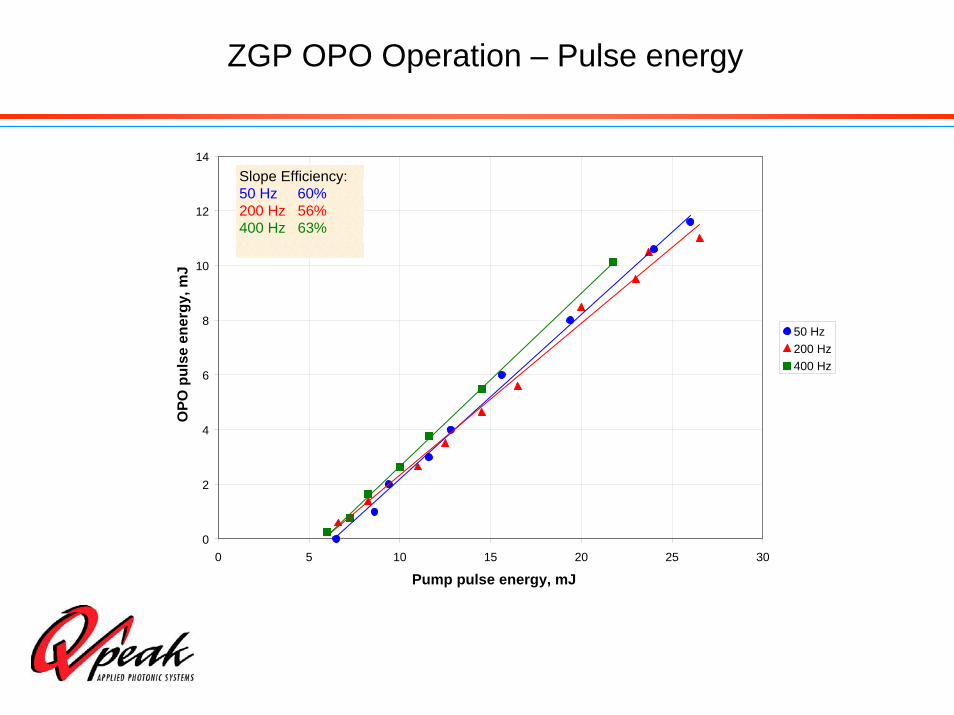
ZGP OPO Operation – Pulse energy
0
2
4
6
8
10
12
14
0 5 10 15 20 25 30
Pump pulse energy, mJ
OPO
pul
se e
nerg
y, m
J
50 Hz200 Hz400 Hz
Slope Efficiency:50 Hz 60%200 Hz 56%400 Hz 63%
Development of an efficient Tm:YLF - Ho:YLF – ZGP laser system:
Conclusions
Ho:YLF laser:• Highest (to the best of our knowledge) CW output of
21 W for 2-μm Ho:YLF laser• Efficient Q-switched operation (up to 37 mJ per pulse)• Repetition rates in wide range from Hz to kHz,
particularly, in 100-400 Hz • High beam quality TEMoo beam
ZGP OPO • Demonstrated > 10 mJ (total) output at 50-400 Hz
rep. rates