high power laser hybrid laser arc welding process ... · pdf file•presentation focuses on...
TRANSCRIPT
High Power Laser Hybrid Laser Arc Welding Process
Advantages and Applications for Bridge
Fabrication Thomas R. Hay, Ph.D
PresidentTECHKNOWSERV CORP.www.techknowserv.com

• Project focused on some HW but primarily HLAW welding of HPS 70W
• Objective was to determine competitive advantage in thick bridge structures
• Reduce welding time by 50% for thick bridge girder flanges
• Presentation focuses on procedure development, welding, mechanical testing and cost benefit analysis
Introduction

• Review of HW welding• The hot-wire laser welding technique combines pre-heated filler
wire with a high power laser beam to achieve high deposition rates in narrow joints.
• The HW process deposits filler material by feeding a pre-heated wire into the process zone.
• Compared to autonomous laser welding, the addition of the pre-heated filler wire to the single laser pass increases the gap bridging capabilities of the process.
• Compared to cold-wire laser welding, less power is needed to melt the added wire, yielding a number of advantages; reduced laser power, increased gap tolerance, and deeper weld penetration.
• Compared to other arc techniques, HW can be placed precisely in in very narrow and deep grooves.
• However, compared to submerged arc welding (SMAW) and gas tungsten arc welding (GTAW) in power piping applications the gap tolerance is tighter and joint preparation must maintain a greater tolerance.
Hot Wire Welding

• Review of HW welding
Hot Wire Welding

• Review of HW welding
Hot Wire Welding
Figure 2.1 Hot wire weld plate fit-up for HPS-70W 1” thick plate.
Figure 2.2 Joint details for hot wire weld J-groove joint for
HPS-70W 1” thick plate.
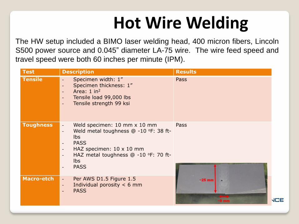
Hot Wire Welding The HW setup included a BIMO laser welding head, 400 micron fibers, Lincoln
S500 power source and 0.045” diameter LA-75 wire. The wire feed speed and
travel speed were both 60 inches per minute (IPM).
Test Description Results
Tensile - Specimen width: 1”- Specimen thickness: 1”- Area: 1 in2
- Tensile load 99,000 lbs- Tensile strength 99 ksi
Pass
Toughness - Weld specimen: 10 mm x 10 mm- Weld metal toughness @ -10 oF: 38 ft-
lbs- PASS- HAZ specimen: 10 x 10 mm- HAZ metal toughness @ -10 oF: 70 ft-
lbs- PASS
Pass
Macro-etch - Per AWS D1.5 Figure 1.5- Individual porosity < 6 mm- PASS

Hot Wire Welding
0
50
100
150
200
250
300
350
400
-12 -10 -8 -6 -4 -2 0 2 4 6 8 10 12
Distance From Approx Center of Weld (mm)
The Vickers Hardness values (V) are presented in Figure 2.3. Base metal
values are in the 200 to 225 V range, HAZ in the 250 to 350 V range, and weld
metal in the 225 to 250 V range

Hot Wire Welding The x-ray image in Figure 2.4 shows sound metal
in the mid-section of the weld. Weld metal lack of
fusion to the base metal is observed towards both
ends of the weld. The incomplete fusion can be
addressed through joint modification, higher laser
output, or preheat

Hot Wire Welding Hot-wire welding was demonstrated on 1” thick HPS 70W plate with a narrow
J-groove joint. The same advantages driving the technique’s development in
other industries apply the bridge fabrication industry:
- Very narrow grooves significantly reducing welding volume
- High deposition rates compared to other torch techniques
- Significant reduction in welding time of thick-section plates and pipes
- Lower distortion and residual stress
- Reduced machining and nondestructive examination effort
Currently there is no comparable low angle (< 45 deg. groove angles)
approved J-groove joints in AWS D1.5 and feedback from bridge fabricators
has generally shown a reluctance to adopt a non-standard joint that will
required specialized tooling to create the narrow bevel angle and tight root
radius. There is also concern from bridge fabricators that the extra time and
cost to machine the J-groove at tight tolerance may offset some cited
advantages.

HLAW HLAW is a welding process that combines the principles of laserbeam welding (LBW) and arc welding. Compared to arc welding,LBW is performed at significantly higher travel speeds. However,the deposition rate is significantly less. By combining the laser andarc welding a hybrid process is created that maximizes penetrationfor narrow root passes and deposition rates for fill passes.
Deep penetration and high speed with better bead
Excellent weld quality
Compatibility with AWS D1.5 joint geometries
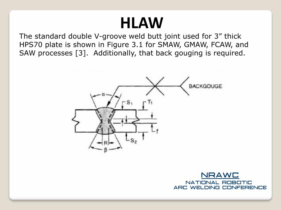
HLAW The standard double V-groove weld butt joint used for 3” thick HPS70 plate is shown in Figure 3.1 for SMAW, GMAW, FCAW, and SAW processes [3]. Additionally, that back gouging is required.

HLAW The HPS70W penetration studies, presented in the following sections, demonstrate that up to 0.625 to 0.900” and 0.780 to 0.875” of penetration are achievable with a 12 kW and 20 kW laser, respectively. 12 kW joint root face was conservatively selected to be 1” due in part to the large amount of heat input required to achieve the deeper penetration. Additional joints with 1.5” long root face were prepared

HLAW TKS’ HLAW welding head was used in conjunction with Penn State’s Applied Research Lab’s 12 kW laser GMAW welding equipment.
The 12 kW laser consisted of a 200- mm-diameter transport fiber connected an IPG Photonics® YLR-12000-L fiber laser.
Additionally, the Edison Welding Institute’s 20 kW laser was also used for penetration studies.
The focus head stand-off was 8.6” initially then changed to 23.4” to mitigate weld spatter and cover lens damage.
A Lincoln Electric® Power Wave 455 M/STT power source was used with welding head.
The torch angle was maintained at 35-40 degrees from vertical. A gas mixture of Ar-97%, 02 3% shielded the weld from the atmosphere at a rate of 50 CFH. The wire feed speed was set to 350 to 500 IPM. The arc voltage was set to 25-35 V, and the current was estimated at 375 – 410 Amps.
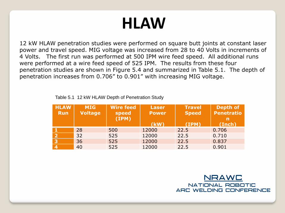
HLAW 12 kW HLAW penetration studies were performed on square butt joints at constant laser power and travel speed. MIG voltage was increased from 28 to 40 Volts in increments of 4 Volts. The first run was performed at 500 IPM wire feed speed. All additional runs were performed at a wire feed speed of 525 IPM. The results from these four penetration studies are shown in Figure 5.4 and summarized in Table 5.1. The depth of penetration increases from 0.706” to 0.901” with increasing MIG voltage.
HLAW Run
MIG Voltage
Wire feed speed(IPM)
Laser Power
(kW)
Travel Speed
(IPM)
Depth of Penetratio
n(Inch)
1 28 500 12000 22.5 0.7062 32 525 12000 22.5 0.7103 36 525 12000 22.5 0.8374 40 525 12000 22.5 0.901
Table 5.1 12 kW HLAW Depth of Penetration Study

HLAW 12 kW HLAW penetration studies were performed on square butt joints at constant laser power and travel speed. MIG voltage was increased from 28 to 40 Volts in increments of 4 Volts. The first run was performed at 500 IPM wire feed speed. All additional runs were performed at a wire feed speed of 525 IPM. The results from these four penetration studies are shown in Figure 5.4 and summarized in Table 5.1. The depth of penetration increases from 0.706” to 0.901” with increasing MIG voltage.
1
a) b)
c) d)
0.706” 0.710”
0.837” 0.901”
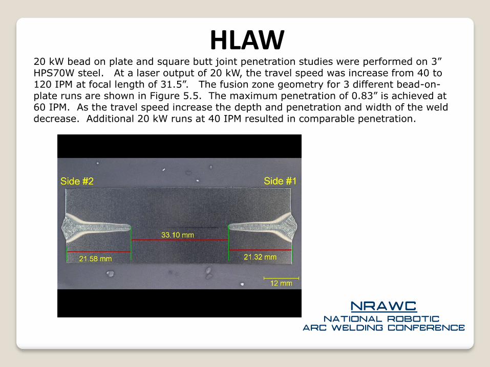
HLAW 20 kW bead on plate and square butt joint penetration studies were performed on 3” HPS70W steel. At a laser output of 20 kW, the travel speed was increase from 40 to 120 IPM at focal length of 31.5”. The fusion zone geometry for 3 different bead-on-plate runs are shown in Figure 5.5. The maximum penetration of 0.83” is achieved at 60 IPM. As the travel speed increase the depth and penetration and width of the weld decrease. Additional 20 kW runs at 40 IPM resulted in comparable penetration.

HLAW Laser Stabilization and fill passes - To determine the transition from keyhole formation to convection, laser power was varied from 2 kW to 12 kW in 2 kW increments. Notice at even at 4kW a keyhole is being formed and porosity is being shown due to turbulence in the welding root. The weld profile at 2 kW shows that the convection transition has occurred at that laser power level.
2 kW 4 kW
8 kW6 kW

HLAW Example Welds – Welding parameters
2 kW 4 kW
8 kW6 kW
Parameter SettingMig voltage (Root) 26 VoltsMig wire feed speed (Root)
350 IPM
Torch stand-off / angle
0.75” / 40
Mig beam separation 0.18” / 4.5 mmFocal length 23.4” (595 mm)Laser power (Root) 12 kWLaser power (Fill) 2800 kWGas flow rate 85 CFHFiller wire LA 90 / .045"Gas 97% Ar 3% O2
Root passes 1 per sideFill passes 15 per side
Parameter SettingMig voltage (Root) 25 VoltsMig voltage (Fill) 30 VoltsMig wire feed speed (Root)
350 IPM
Torch stand-off / angle
0.75” / 40
Mig beam separation
0.18” / 4.5 mm
Focal length 23.4” (595 mm)Laser power (Root) 12 kWLaser power (Fill) 2000 - 2500 kWGas flow rate 85 CFHFiller wire Metal Core / 1/16”Gas 97% Ar 3% O2
Root passes 1 per sideFill passes 15 per side

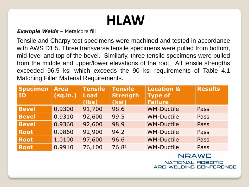
HLAW Example Welds – Metalcore fill
2 kW 4 kW
8 kW6 kW
3/16”
1/8”

HLAW Example Welds – Metalcore fill
2 kW 4 kW
8 kW6 kW
¼”

HLAW Example Welds – Metalcore fill
2 kW 4 kW
8 kW6 kW
1”

HLAW Example Welds – Metalcore fill
2 kW 4 kW
8 kW6 kW
Vickers Hardness (traveling left to
right)Position
3 Position
4Position
5 228 224 219239 223 237239 265 283250 264 312250 272 268250 259 235230 238 240250 236 230229 234 233249 241 237
The pre-heat average hardness decreased 20% compared to the Weld 3 (no pre-heat) average
hardness. A 7% decrease in average hardness compared to the hot-wire values presented earlier. A
small 5% and 3% decrease in the pre-heat peak hardness was also observed compared to the no pre-
heat HLAW and HW values, respectively.
HLAW Example Welds – Metalcore fill
2 kW 4 kW
8 kW6 kW
SpecimenID
Area(sq.in.)
TensileLoad(lbs)
TensileStrength(ksi)
Location & Type of Failure
Results
Bevel 0.9300 91,700 98.6 WM-Ductile Pass
Bevel 0.9310 92,600 99.5 WM-Ductile Pass
Bevel 0.9360 92,600 98.9 WM-Ductile Pass
Root 0.9860 92,900 94.2 WM-Ductile Pass
Root 1.0100 97,600 96.6 WM-Ductile Pass
Root 0.9910 76,100 76.81 WM-Ductile Pass
Tensile and Charpy test specimens were machined and tested in accordance
with AWS D1.5. Three transverse tensile specimens were pulled from bottom,
mid-level and top of the bevel. Similarly, three tensile specimens were pulled
from the middle and upper/lower elevations of the root. All tensile strengths
exceeded 96.5 ksi which exceeds the 90 ksi requirements of Table 4.1
Matching Filler Material Requirements.

HLAW Example Welds – Metalcore fill
2 kW 4 kW
8 kW6 kW
SpecimenID
Temp
(oF)
Energy
(ft-lbs)
Lat. Exp.(in.)
Shear
(%)
Size
(mm)
Results
WM -20 64 0.0720 10 10x10 Pass zones 1&21
WM -20 56 0.0400 10 10x10 Pass zones 1&21
WM -20 53 0.0690 10 10x10 Pass zones 1&21
Root -20 108 0.0820 15 10x10 Pass zones 1&21
Root -20 25 0.0210 10 10x10 Pass zones 1&21
Root -20 32 0.0230 10 10x10 Pass zones 1&21
HAZ -20 100 0.0590 10 10x10 Pass zones 1&21
HAZ -20 76 0.0660 10 10x10 Pass zones 1&21
HAZ -20 87 0.0540 10 10x10 Pass zones 1&21
The root weld and root HAZ Charpy V-notch impact specimens were notched in the root and HAZ,
respectively, and pulled from the top/bottom and middle elevations of the root. The weld metal
specimens were pulled from sound metal in the bevel of the weld. The lowest measurements of 26
and 35 ft-lbs are found in the middle and bottom side of the root, respectively. At -20oF, these values
still exceeded the minimum impact energy value of 25 ft-lbs at -10oF for HPS 70W filler materials
values defined by AWS D1.5 for Zones 1 and 2.

Summary
2 kW 4 kW
8 kW6 kW
Sound laser hot-wire (HW) and hybrid laser arc welds (HLAW) that pass key Bridge Welding Code (BWC) quality control guidelines were produced through parameter development and observations made during welding.
The 1” hot-wire weld produced, demonstrated clearly that HW creates a sound weld with tensile and toughness results that meet and exceed industry requirement defined in the BWC.
Twelve HLAW weld joints were produced, and during this process, parameters were adjusted incrementally based on feedback from nondestructive and mechanical testing.
Excellent mechanical properties were confirmed in the root weld metal and heat affected zone that meet and exceed the BWC and the Guide for Highway Bridge Fabrication with HPS 70W Steel.
At this point, it is unknown if HLAW can be a competitive technology for the fill passes compared to SAW. There may be tremendous economic benefit to creating a hybrid process that uses HLAW for the root and SAW for the fill passes.