high-resolution 3d optical sensing and real-time 3d video
TRANSCRIPT
High-resolution 3D optical sensing and real-time 3D video datastreaming*
Tyler Bell1,2 and Song Zhang2
Abstract—The first part of this paper discusses the high-resolution, real-time 3D optical sensing techniques that wedeveloped in the optics community. Such technologies couldbenefit the advanced intelligent mechatronics community asanother sensing tool. The second part of this paper discussesour recent development on 3D sensing data compressionand streaming that could open new opportunities for themechatronics community. Our 3D optical sensing technique isbased on the digital fringe projection (DFP) method that hasmerits of speed, resolution, and accuracy, as well flexibilitywhen comparing with other 3D optical imaging methods. Ournovel compression method drastically reduces data sizes, andthrough seamless integration with our 3D sensing system, allowsfor real-time high-quality 3D data delivery across standardwired and wireless networks. This paper introduces the basicprinciples of each technology and casts our perspectives onpossible applications that our technologies could enable for themechatronics community.
I. INTRODUCTIONAdvances in two-dimensional (2D) optical sensing and
machine/computer vision have provided integrated smartsensing systems for numerous applications [14]. By addingone more dimension, advanced three-dimensional (3D) opti-cal sensing and vision technologies can have much greaterimpact to scientific researches (e.g., mechatronics, medicine,computer sciences) and industrial practices (e.g., manufac-turing, intelligent robotics).Due to the increased computational power available on
personal computers, mobile devices, and in cloud computing,high-speed and high-accuracy 3D sensing techniques havebeen increasingly sought after by scientists in fields suchas biomedical engineering and computer science, by engi-neers from various industries including manufacturing andentertainment, and even by ordinary people with differenttechnical backgrounds [25]. The availability of consumer-level real-time 3D sensing technologies (e.g., MicrosoftKinect, Intel RealSense, Apple iPhone X) further drivesthe developments and applications of 3D optical sensingtechnologies.3D optical sensing methods can be broadly classified
into two categories: passive and active methods. Passivetechniques require no active illumination for 3D sensing,and one of the most popular passive methods used in the
*This work was supported by National Science Foundation under thegrant numbers IIS-1637961
1 Tyler Bell is a graduate student with School of Electrical and ComputerEngineering, Purdue University, 465 Northwestern Ave, West Lafayette, IN47907, United States [email protected]
2 Song Zhang is with Faculty of School of Mechanical Engineering,Purdue University, 585 Purdue Mall, West Lafayette, IN 47907, UnitedStates [email protected]
mechatronics community is based on stereo vision princi-ples [5, 13]. The stereo-vision technique determines depthinformation by capturing images from at least two differentperspectives, finding the corresponding points which aresimilar between those images, and then by utilizing thecalibrated camera parameters and the triangulation relation-ship between image pairs. Despite its simple system setup,low cost, and rapid image acquisition, stereo vision is notextensively used in applications where high sensing accuracyis required. This is primarily because such a method requiresdetermining corresponding points from a pair of images, andit is fundamentally difficult to achieve high accuracy if anobject does not present rich surface texture.Active methods eliminate the fundamental limitation of the
stereo method by actively illuminating the object with pre-known information. For example, the time of light (TOF)technique actively emits modulated light in the time domainand collects the modulated light scattered back by the object.Depth information can then be calculated by determining thetime delay from the time that the signal left the device untilthe signal returned to the device [7]. Since the TOF methoddoes not require triangulation for 3D sensing, its footprintcan be small, making it applicable for long range 3D sensingand mobile sensing. For example, the light detection andranging (LIDAR) technology is based on TOF for long rangesensing, and Microsoft Kinect II employs the TOF for mobileapplications. However, the achieved depth resolution for TOFsystems may not be high as, due to the extremely hightraveling speed of light, it is difficult to measure time delaysaccurately.The structured light method, another of the active methods,
reconstructs 3D information by replacing one of the cameraswithin a stereo vision system with a projection device,such that structured pattern(s) can be actively projected forcorrespondence establishment [19]. The projection devicecan be a fixed pattern projector (such as those used inApple iPhone X or Microsoft Kinect), or a programmableand flexible digital video projector. Due to the flexibilityof digital video projectors, different types of structuredpatterns can be used, such as random patterns [8], binarystructured patterns [19], multi-gray level patterns [18], aswell as sinusoidal patterns [23]. Compared with all of thedifferent types of patterns, using the sinusoidal structuredpatterns, especially combined with phase-shifting algorithms,is overwhelmingly advantageous [21]. The sinusoidal struc-tured patterns are often referred to as fringe patterns in theoptics community, and the structured light method whichuses digital fringe patterns for 3D optical sensing is often
Proceedings of the 2018 IEEE/ASME InternationalConference on Advanced Intelligent Mechatronics (AIM),Auckland, New Zealand, July 9-12, 2018
WAT3.5
978-1-5386-1854-7/18/$31.00 ©2018 IEEE 521
called digital fringe projection (or DFP).Leveraging the unique projection mechanism of single-
chip digital-light-processing (DLP) technologies, Zhang andHuang [26] developed what was probably the first-ever, high-speed 3D optical sensing system that achieved 3D shapeacquisition, reconstruction, and display at an unprecedented40 Hz with over 250,000 measurement points per frame.Following this endeavor, numerous real-time techniques in-cluding [10, 15, 20, 28] have been developed for 3D shapemeasurement, leveraging both advanced hardware technolo-gies (e.g., GPU) and new innovations on software algorithms.The size of 3D data is typically a magnitude larger than
that of its 2D counterpart. Therefore, compressing 3D datahas emerged as an important issue to be dealt with for largesize data storage and visualization. Conventional 3D datarepresentation formats (e.g., STL, OBJ) are effective andgeneric, yet they usually store (x, y, z) coordinates for eachvertex, the connectivity information between vertices, and of-ten surface normal information thus utilizing a lot of storagespace. Given our knowledge and experience on 3D opticalsensing system development, we developed a sequence of 3Dcompression techniques for 3D structured light sensors [2–4, 11, 17, 22] that convert 3D data into standard 2D imageformats such that the 2D images can be further compressedusing mature 2D image compression methods. Sequences of2D images can also be further compressed using 2D videocompression techniques such as using H.264 codec [12].Recently, Bell et al. [1] developed a novel platform,
dubbed Holostream, which enables high-quality 3D videocommunications across existing standard wireless networksand existing mobile hardware devices (e.g., iPhones andiPads). Such a platform advances the quality and capabilitiesof applications already utilizing real-time 3D data delivery(e.g., teleconferencing, telepresence), and could also enableapplications where real-time delivery of high-resolution,high-accuracy 3D video data is especially critical, such asrobot-robot and human-robot interactions.This paper explains the basic principles behind real-time
3D optical sensing using DFP in addition to real-time 3Dvideo compression and streaming techniques. Experimentaldata will be presented to demonstrate the performance ofeach technology.
II. PRINCIPLE
This section briefly discusses the principles of real-time3D optical sensing using a phase-shifting method, as well asreal-time 3D video compression and streaming techniques.
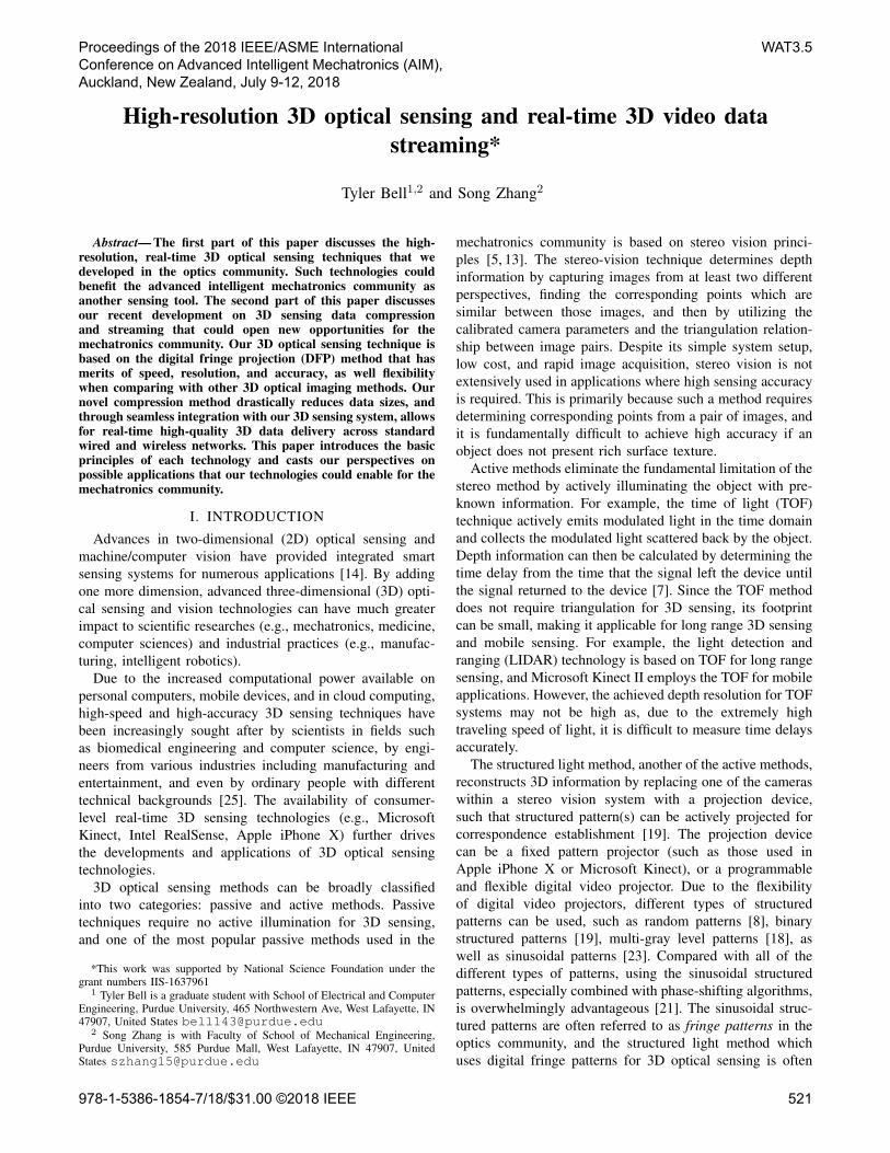
A. Real-time 3D sensing using digital fringe projection(DFP) techniquesFigure 1 shows the schematic diagram of a DFP system
for 3D optical sensing using the triangulation approach.Using this figure, we can see that Point A on the imagingunit, Point C on the projection unit, and Point B on theobject surface form a triangle; such a triangular relationshipcan be used for 3D reconstruction when the calibrationparameters of the camera and the projector are known. The
projected pattern contains stripes that vary sinusoidally inone direction, and thus each varying line on the projectorcan encode unique information. To find the correspondingpoint C on the projection device for a given camera imagepoint A, epipolar geometry is often used [23].
Object
Projector fringe
Camera image
Phase line
Projector pixel
Camera pixel
Object point
Phase line
Baseline
C A
B
ED
Z
Fig. 1. Schematic configuration of the structured light system. A projectorshines pre-defined structured patterns to the object surface; the object surfacegeometry distorts the patterns; the camera captures the distorted patterns;and the software analyzes the camera images to find their correspondencewith the projector in order to form triangulation for 3D reconstruction.
Phase-shifting methods have been extensively employedin high-accuracy 3D optical metrology due to the advantagesof achievable speed, resolution, and accuracy [16]. Amongthose phase-shifting algorithms, the three-step or four-stepphase-shifting algorithm is typically used for high-speedapplications. For a three-step phase-shifting algorithm withequal phase shifts, the intensity of the three fringe imagescan be described as
I1(x, y) = I
0(x, y) + I
00(x, y) cos(�� 2⇡/3), (1)
I2(x, y) = I
0(x, y) + I
00(x, y) cos(�), (2)
I3(x, y) = I
0(x, y) + I
00(x, y) cos(�+ 2⇡/3). (3)
Here, I 0(x, y) is the average intensity, I 00(x, y) is the inten-sity modulation, and �(x, y) is the phase to be solved for.Simultaneously solving Eq. (1)-(3), the phase can be obtainedvia
�(x, y) = tan
�1hp
3(I1 � I3)/(2I2 � I1 � I3)
i. (4)
Equation (4) provides phase values ranging from �⇡ to +⇡
with 2⇡ phase discontinuities. A phase unwrapping algorithmis required to determine those 2⇡ discontinuous locationsand remove them. In general, phase unwrapping can beclassified as either relative phase unwrapping or absolutephase unwrapping. The former produces an unwrapped phasemap that can be used to measure relative 3D surface informa-tion. Conventional spatial phase unwrapping algorithms [6]typically belong to this category. In contrast, by using apredefined absolute reference, absolute phase unwrappingmethods [24] can obtain an unwrapped phase map thatcan be used to recover absolute 3D shape of the object.Temporal phase unwrapping algorithms typically generateabsolute phase maps, for example. In this research, we em-ploy the enhanced two-frequency temporal phase unwrappingmethod [9] to obtain absolute phase for absolute 3D shapemeasurement.
978-1-5386-1854-7/18/$31.00 ©2018 IEEE 522
In addition to phase, solving Eq. (1)-(3) can also producea texture image which is perfectly aligned with 3D geometryvia
It(x, y) =I1 + I2 + I3
3
. (5)
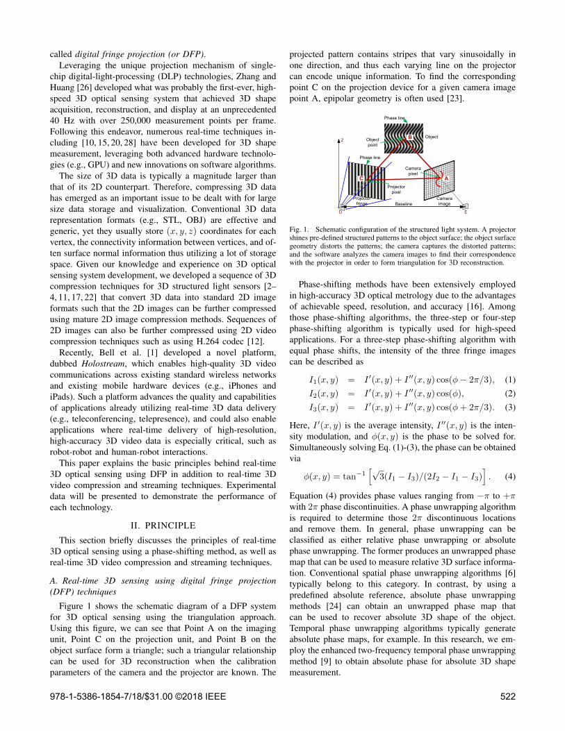
Since the texture image is essentially a regular photograph ofthe object it can readily be used for enhanced visualizationsor for information analysis.Figure 2 shows an example of using the three-step phase-
shifting algorithm for 3D optical sensing. Figures 2(a)-2(c)show three high-frequency fringe patterns. Using these threephase-shifted fringe patterns, we can compute the wrappedphase (Fig. 2(d)) and the raw texture (Fig. 2(k)). Figures 2(e)-2(g) show three low-frequency fringe patterns, from whichthe low-frequency phase can be calculated, as shown inFig. 2(h). The low-frequency phase map can be used tounwrap the high-frequency phase map using the enhancetwo-frequency phase unwrapping method [9]. Figure 2(i)shows the unwrapped phase map. The unwrapped phase mapcan then be further processed to reconstruct 3D informationusing the system’s calibration parameters. Figure 2(j) showsthe 3D result rendered in shaded mode. The raw textureshown in Fig. 2(k) is Bayer coded, which can be converted tocolor texture using a demosaicing algorithm; Fig. 2(l) showsthe recovered color texture. In this example, the system wascalibrated using the method discussed in Reference [27]. Thecamera resolution used for this experiment was 480 ⇥ 640:a rather low resolution, yet the details are well captured byusing the phase-shifting method.Zhang and Huang [26] developed a 3D optical imaging
system that simultaneously captured, processed, and dis-played 3D geometries at 40 Hz with over 250,000 mea-surement points per frame, something which was unprece-dented at that time. The basic principle behind such a real-time 3D imaging technology is to take advantage of theunique projection mechanism of a single-chip digital lightprocessing (DLP) projector. Such projectors naturally switchbetween three images (i.e., red, green, and blue channels)at a default refresh rate (which was 80 Hz at that time).Today, the aforementioned enhanced two-frequency phase-shifting algorithm has been successfully implemented onDLP development kits to achieve real-time 3D measurementspeeds of 30 Hz (or faster when utilizing a modern GPU toperform the 3D data processing and reconstruction).
B. 3D sensing data compression
Raw 3D video data is enormously large before compres-sion, requiring bandwidths of over 1 Gbps (Gigabit persecond) for streaming, which is difficult to achieve acrossstandard wireless networks. To address this, we have devel-oped a two-stage 3D video compression technique whichframe-by-frame (1) encodes 3D geometry and color textureinto standard 2D images and (2) further compresses the2D image sequence using standard 2D video compressioncodecs.As mentioned above, our 3D sensing technique recovers
3D data from a 2D phase map and, since this process is
(a) (b) (c) (d)
(e) (f) (g) (h)
(i) (j) (k) (l)
Fig. 2. Example of using enhanced two-frequency phase-shifting methodfor high-resolution 3D optical sensing. (a)-(c) Three phase-shifted high-frequency fringe patterns; (d) wrapped high-frequency phase map; (e)-(g) three phase-shifted low-frequency fringe patterns; (h) wrapped low-frequency phase map; (i) recovered 3D shape; (k) raw Bayer-coded textureimage; (l) color texture after demosaicing. The camera resolution used forthis experiment is 480⇥ 640.
performed pixel-by-pixel, there exists a one-to-one mappingbetween the unwrapped phase �(i, j) of a point and itsrecovered (x, y, z) coordinate. In other words, the 2D phasemap already contains a precise encoding of the 3D coor-dinates. Therefore, as long as the 2D phase map can beencoded, its 3D information can be recovered later on.For each pixel (i, j) within the unwrapped phase map, a
scaled corresponding phase value e� is encoded as sine and
cosine functions,
R(i, j) = 127.5 + 127.5 sin
e�, (6)
G(i, j) = 127.5 + 127.5 cos
e�, (7)
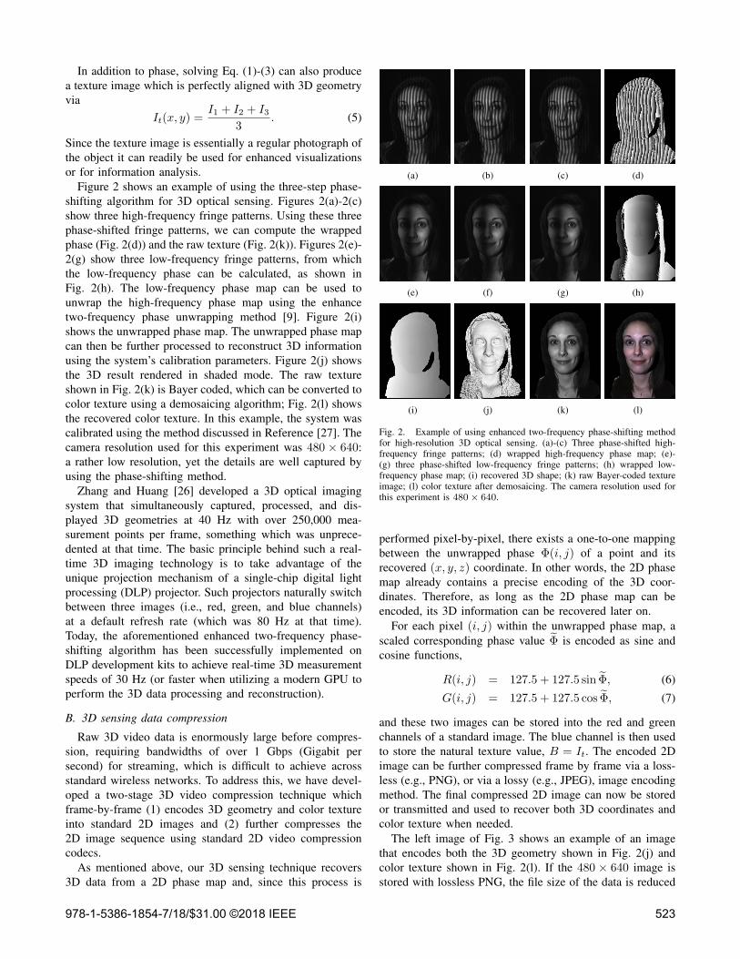
and these two images can be stored into the red and greenchannels of a standard image. The blue channel is then usedto store the natural texture value, B = It. The encoded 2Dimage can be further compressed frame by frame via a loss-less (e.g., PNG), or via a lossy (e.g., JPEG), image encodingmethod. The final compressed 2D image can now be storedor transmitted and used to recover both 3D coordinates andcolor texture when needed.The left image of Fig. 3 shows an example of an image
that encodes both the 3D geometry shown in Fig. 2(j) andcolor texture shown in Fig. 2(l). If the 480 ⇥ 640 image isstored with lossless PNG, the file size of the data is reduced
978-1-5386-1854-7/18/$31.00 ©2018 IEEE 523
from 32 MB to 288 KB, achieving a compression ratio ofapproximately 112:1 versus storing the same informationwithin the OBJ format. As shown in the last image ofFig. 3(d), the difference between the original geometry andthe geometry reconstructed from the PNG image appears tobe random noise which may be caused by small amounts ofquantization.
(a) (b) (c) (d)
Fig. 3. Encoding and decoding 3D geometry and color texture. A losslessPNG format results in a compression ratio of approximately 112:1. (a) Theencoded RGB PNG image; (b) the recovered color texture; (c) the recovered3D geometry; (d) an overlay of the reconstructed 3D geometry on top ofthe original 3D geometry (gray color represents recovered geometry and redrepresents the original geometry).
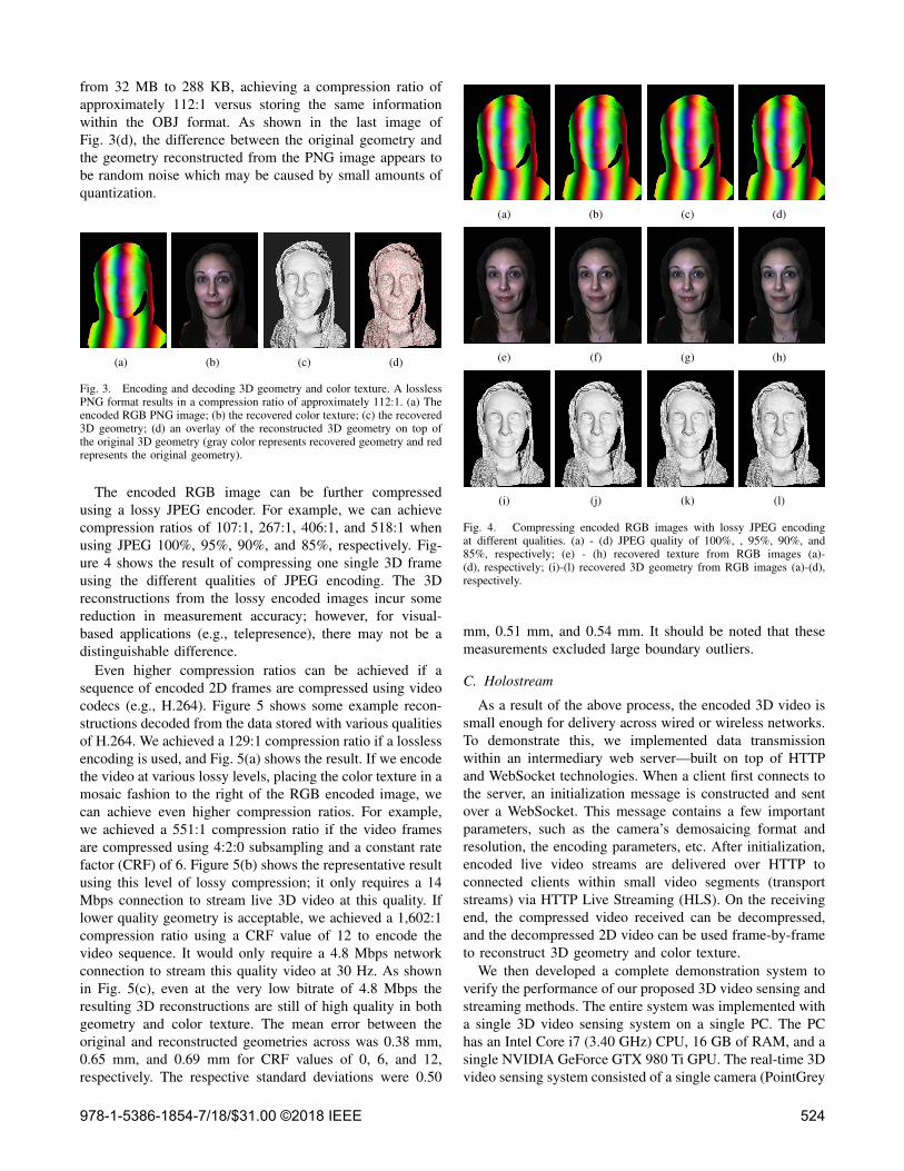
The encoded RGB image can be further compressedusing a lossy JPEG encoder. For example, we can achievecompression ratios of 107:1, 267:1, 406:1, and 518:1 whenusing JPEG 100%, 95%, 90%, and 85%, respectively. Fig-ure 4 shows the result of compressing one single 3D frameusing the different qualities of JPEG encoding. The 3Dreconstructions from the lossy encoded images incur somereduction in measurement accuracy; however, for visual-based applications (e.g., telepresence), there may not be adistinguishable difference.Even higher compression ratios can be achieved if a
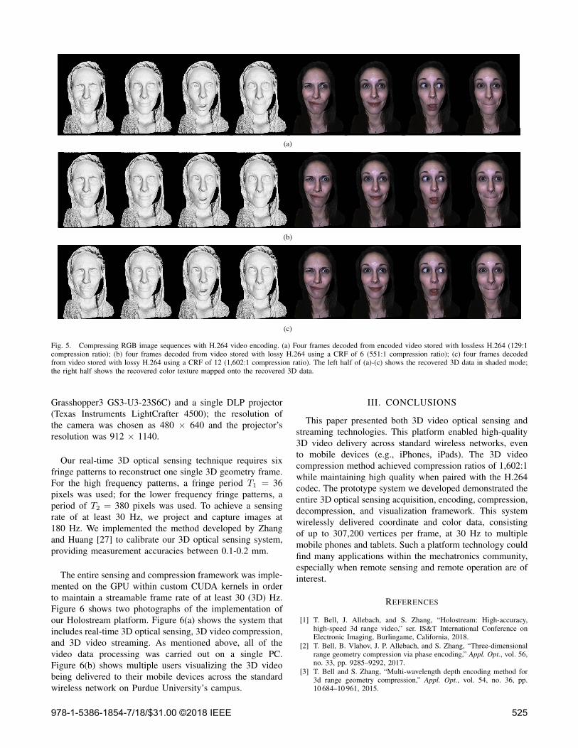
sequence of encoded 2D frames are compressed using videocodecs (e.g., H.264). Figure 5 shows some example recon-structions decoded from the data stored with various qualitiesof H.264. We achieved a 129:1 compression ratio if a losslessencoding is used, and Fig. 5(a) shows the result. If we encodethe video at various lossy levels, placing the color texture in amosaic fashion to the right of the RGB encoded image, wecan achieve even higher compression ratios. For example,we achieved a 551:1 compression ratio if the video framesare compressed using 4:2:0 subsampling and a constant ratefactor (CRF) of 6. Figure 5(b) shows the representative resultusing this level of lossy compression; it only requires a 14Mbps connection to stream live 3D video at this quality. Iflower quality geometry is acceptable, we achieved a 1,602:1compression ratio using a CRF value of 12 to encode thevideo sequence. It would only require a 4.8 Mbps networkconnection to stream this quality video at 30 Hz. As shownin Fig. 5(c), even at the very low bitrate of 4.8 Mbps theresulting 3D reconstructions are still of high quality in bothgeometry and color texture. The mean error between theoriginal and reconstructed geometries across was 0.38 mm,0.65 mm, and 0.69 mm for CRF values of 0, 6, and 12,respectively. The respective standard deviations were 0.50
(a) (b) (c) (d)
(e) (f) (g) (h)
(i) (j) (k) (l)
Fig. 4. Compressing encoded RGB images with lossy JPEG encodingat different qualities. (a) - (d) JPEG quality of 100%, , 95%, 90%, and85%, respectively; (e) - (h) recovered texture from RGB images (a)-(d), respectively; (i)-(l) recovered 3D geometry from RGB images (a)-(d),respectively.
mm, 0.51 mm, and 0.54 mm. It should be noted that thesemeasurements excluded large boundary outliers.
C. Holostream
As a result of the above process, the encoded 3D video issmall enough for delivery across wired or wireless networks.To demonstrate this, we implemented data transmissionwithin an intermediary web server—built on top of HTTPand WebSocket technologies. When a client first connects tothe server, an initialization message is constructed and sentover a WebSocket. This message contains a few importantparameters, such as the camera’s demosaicing format andresolution, the encoding parameters, etc. After initialization,encoded live video streams are delivered over HTTP toconnected clients within small video segments (transportstreams) via HTTP Live Streaming (HLS). On the receivingend, the compressed video received can be decompressed,and the decompressed 2D video can be used frame-by-frameto reconstruct 3D geometry and color texture.We then developed a complete demonstration system to
verify the performance of our proposed 3D video sensing andstreaming methods. The entire system was implemented witha single 3D video sensing system on a single PC. The PChas an Intel Core i7 (3.40 GHz) CPU, 16 GB of RAM, and asingle NVIDIA GeForce GTX 980 Ti GPU. The real-time 3Dvideo sensing system consisted of a single camera (PointGrey
978-1-5386-1854-7/18/$31.00 ©2018 IEEE 524
0"
6"
12"
Just"for"ref…"
(a)
0"
6"
12"
Just"for"ref…"
(b)
0"
6"
12"
Just"for"ref…"
(c)
Fig. 5. Compressing RGB image sequences with H.264 video encoding. (a) Four frames decoded from encoded video stored with lossless H.264 (129:1compression ratio); (b) four frames decoded from video stored with lossy H.264 using a CRF of 6 (551:1 compression ratio); (c) four frames decodedfrom video stored with lossy H.264 using a CRF of 12 (1,602:1 compression ratio). The left half of (a)-(c) shows the recovered 3D data in shaded mode;the right half shows the recovered color texture mapped onto the recovered 3D data.
Grasshopper3 GS3-U3-23S6C) and a single DLP projector(Texas Instruments LightCrafter 4500); the resolution ofthe camera was chosen as 480 ⇥ 640 and the projector’sresolution was 912 ⇥ 1140.
Our real-time 3D optical sensing technique requires sixfringe patterns to reconstruct one single 3D geometry frame.For the high frequency patterns, a fringe period T1 = 36pixels was used; for the lower frequency fringe patterns, aperiod of T2 = 380 pixels was used. To achieve a sensingrate of at least 30 Hz, we project and capture images at180 Hz. We implemented the method developed by Zhangand Huang [27] to calibrate our 3D optical sensing system,providing measurement accuracies between 0.1-0.2 mm.
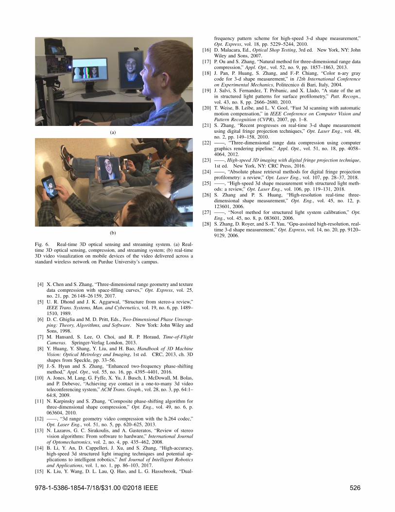
The entire sensing and compression framework was imple-mented on the GPU within custom CUDA kernels in orderto maintain a streamable frame rate of at least 30 (3D) Hz.Figure 6 shows two photographs of the implementation ofour Holostream platform. Figure 6(a) shows the system thatincludes real-time 3D optical sensing, 3D video compression,and 3D video streaming. As mentioned above, all of thevideo data processing was carried out on a single PC.Figure 6(b) shows multiple users visualizing the 3D videobeing delivered to their mobile devices across the standardwireless network on Purdue University’s campus.
III. CONCLUSIONS
This paper presented both 3D video optical sensing andstreaming technologies. This platform enabled high-quality3D video delivery across standard wireless networks, evento mobile devices (e.g., iPhones, iPads). The 3D videocompression method achieved compression ratios of 1,602:1while maintaining high quality when paired with the H.264codec. The prototype system we developed demonstrated theentire 3D optical sensing acquisition, encoding, compression,decompression, and visualization framework. This systemwirelessly delivered coordinate and color data, consistingof up to 307,200 vertices per frame, at 30 Hz to multiplemobile phones and tablets. Such a platform technology couldfind many applications within the mechatronics community,especially when remote sensing and remote operation are ofinterest.
REFERENCES
[1] T. Bell, J. Allebach, and S. Zhang, “Holostream: High-accuracy,high-speed 3d range video,” ser. IS&T International Conference onElectronic Imaging, Burlingame, California, 2018.
[2] T. Bell, B. Vlahov, J. P. Allebach, and S. Zhang, “Three-dimensionalrange geometry compression via phase encoding,” Appl. Opt., vol. 56,no. 33, pp. 9285–9292, 2017.
[3] T. Bell and S. Zhang, “Multi-wavelength depth encoding method for3d range geometry compression,” Appl. Opt., vol. 54, no. 36, pp.10 684–10 961, 2015.
978-1-5386-1854-7/18/$31.00 ©2018 IEEE 525
(a)
(b)
Fig. 6. Real-time 3D optical sensing and streaming system. (a) Real-time 3D optical sensing, compression, and streaming system; (b) real-time3D video visualization on mobile devices of the video delivered across astandard wireless network on Purdue University’s campus.
[4] X. Chen and S. Zhang, “Three-dimensional range geometry and texturedata compression with space-filling curves,” Opt. Express, vol. 25,no. 21, pp. 26 148–26 159, 2017.
[5] U. R. Dhond and J. K. Aggarwal, “Structure from stereo-a review,”IEEE Trans. Systems, Man. and Cybernetics, vol. 19, no. 6, pp. 1489–1510, 1989.
[6] D. C. Ghiglia and M. D. Pritt, Eds., Two-Dimensional Phase Unwrap-ping: Theory, Algorithms, and Software. New York: John Wiley andSons, 1998.
[7] M. Hansard, S. Lee, O. Choi, and R. P. Horaud, Time-of-FlightCameras. Springer-Verlag London, 2013.
[8] Y. Huang, Y. Shang, Y. Liu, and H. Bao, Handbook of 3D MachineVision: Optical Metrology and Imaging, 1st ed. CRC, 2013, ch. 3Dshapes from Speckle, pp. 33–56.
[9] J.-S. Hyun and S. Zhang, “Enhanced two-frequency phase-shiftingmethod,” Appl. Opt., vol. 55, no. 16, pp. 4395–4401, 2016.
[10] A. Jones, M. Lang, G. Fyffe, X. Yu, J. Busch, I. McDowall, M. Bolas,and P. Debevec, “Achieving eye contact in a one-to-many 3d videoteleconferencing system,” ACM Trans. Graph., vol. 28, no. 3, pp. 64:1–64:8, 2009.
[11] N. Karpinsky and S. Zhang, “Composite phase-shifting algorithm forthree-dimensional shape compression,” Opt. Eng., vol. 49, no. 6, p.063604, 2010.
[12] ——, “3d range geometry video compression with the h.264 codec,”Opt. Laser Eng., vol. 51, no. 5, pp. 620–625, 2013.
[13] N. Lazaros, G. C. Sirakoulis, and A. Gasteratos, “Review of stereovision algorithms: From software to hardware,” International Journalof Optomechatronics, vol. 2, no. 4, pp. 435–462, 2008.
[14] B. Li, Y. An, D. Cappelleri, J. Xu, and S. Zhang, “High-accuracy,high-speed 3d structured light imaging techniques and potential ap-plications to intelligent robotics,” Intl Journal of Intelligent Roboticsand Applications, vol. 1, no. 1, pp. 86–103, 2017.
[15] K. Liu, Y. Wang, D. L. Lau, Q. Hao, and L. G. Hassebrook, “Dual-
frequency pattern scheme for high-speed 3-d shape measurement,”Opt. Express, vol. 18, pp. 5229–5244, 2010.
[16] D. Malacara, Ed., Optical Shop Testing, 3rd ed. New York, NY: JohnWiley and Sons, 2007.
[17] P. Ou and S. Zhang, “Natural method for three-dimensional range datacompression,” Appl. Opt., vol. 52, no. 9, pp. 1857–1863, 2013.
[18] J. Pan, P. Huang, S. Zhang, and F.-P. Chiang, “Color n-ary graycode for 3-d shape measurement,” in 12th International Conferenceon Experimental Mechanics, Politecnico di Bari, Italy, 2004.
[19] J. Salvi, S. Fernandez, T. Pribanic, and X. Llado, “A state of the artin structured light patterns for surface profilometry,” Patt. Recogn.,vol. 43, no. 8, pp. 2666–2680, 2010.
[20] T. Weise, B. Leibe, and L. V. Gool, “Fast 3d scanning with automaticmotion compensation,” in IEEE Conference on Computer Vision andPattern Recognition (CVPR), 2007, pp. 1–8.
[21] S. Zhang, “Recent progresses on real-time 3-d shape measurementusing digital fringe projection techniques,” Opt. Laser Eng., vol. 48,no. 2, pp. 149–158, 2010.
[22] ——, “Three-dimensional range data compression using computergraphics rendering pipeline,” Appl. Opt., vol. 51, no. 18, pp. 4058–4064, 2012.
[23] ——, High-speed 3D imaging with digital fringe projection technique,1st ed. New York, NY: CRC Press, 2016.
[24] ——, “Absolute phase retrieval methods for digital fringe projectionprofilometry: a review,” Opt. Laser Eng., vol. 107, pp. 28–37, 2018.
[25] ——, “High-speed 3d shape measurement with structured light meth-ods: a review,” Opt. Laser Eng., vol. 106, pp. 119–131, 2018.
[26] S. Zhang and P. S. Huang, “High-resolution real-time three-dimensional shape measurement,” Opt. Eng., vol. 45, no. 12, p.123601, 2006.
[27] ——, “Novel method for structured light system calibration,” Opt.Eng., vol. 45, no. 8, p. 083601, 2006.
[28] S. Zhang, D. Royer, and S.-T. Yau, “Gpu-assisted high-resolution, real-time 3-d shape measurement,” Opt. Express, vol. 14, no. 20, pp. 9120–9129, 2006.
978-1-5386-1854-7/18/$31.00 ©2018 IEEE 526