high resolution and short distance retinal imaging...
TRANSCRIPT

John Covey Optical System Design – Project 1 3/10/05
High Resolution and Short Distance Retinal Imaging Design
Introduction
Currently, when one thinks of head-mounted displays, an image of large, bulky
virtual reality headgear comes to mind that is about as large as a helmet. A vision of the
future head-mounted display could entail a pair of sunglasses that is able to project light
from a portable video source onto the retina. A market of current interest for such a
device is televisions, where one desires to project the image of a very large TV screen
into the eye while taking up the minimal space that glasses would allow. This presents
two interesting challenges. First, one must be able to house a video source that is capable
of displaying enough pixels to match the video resolution of a television, preferably high
definition resolution. Second, this video source must then interface with a small, portable
optical system that is able to produce the illusion that the video source is a television
some distance in front of the user. This report will solely focus on the second of the two
issues, for it is necessary to demonstrate that such an optical system is possible before
one undergoes the arduous task of creating a small, portable, and high resolution video
source only to discover that it is physically impossible to image such a source onto the
retina in such a small, portable space.

Specifications
In order to adequately design the imaging system, an target situation containing
only the eye and a video source of a certain size, resolution, and distance away must be
specified. Since the niche market in which possible sources of funding are interested is
televisions, the best TV situation money can currently buy is chosen in order to determine
the feasibility of possible competition in this market. Thus, the target situation is as
follows: a human eye is watching a high definition TV which is 2 meters by 2 meters in
dimension and is 4 meters away. High definition television has been recently augmented
to 1920x1000 pixels, but for simplicity of calculation, the target situation shall contain
2000x2000 pixels instead. Magnification calculations dictate that such an object would
produce an 8.5mm x 8.5mm image on the retina. (These calculations are included in
Appendix A) Therefore, the optical system to replace the TV must ultimately produce an
8.5mm x 8.5mm image on the retina with a 2000x2000 pixel resolution. Lastly, it is
preferred that this optical system becomes small and simple enough so that it can be
head-mounted and be likened to wearing a pair of sunglasses.
Choice of Layout
Since the nature of the video source for this proposed system must be at least
vaguely understood in order to create an optical design, it will be assumed that pixels of a
10 micron pitch will be responsible for displaying the visual object. (The effect of
varying the pixel pitch will be explored later) Therefore, the initial total object size is
2cm x 2cm.

One could speculate that if the eye were used as the only optical element, the
system and its cost would be minimized. However, rudimentary calculation shows that in
order to image the object onto the retina with the target image size, the eye would quickly
overstrain itself in order to bring the object into focus. (See Appendix A) Therefore, at
least one external lens is required in order to make the design attainable. Since the eye is
most relaxed while focusing on an object that is almost infinity, it seems logical that a
telescoping system using an external lens and the eye’s focal power should be the next
attempt. Other designs were speculated upon where relay or field lenses were introduced
into the system, but the overall distance of the system always increased with each
additional element, making the end result highly undesirable. Moreover, due to the
required simplicity of the resulting head-mount, a system with a single external focusing
element was selected and analyzed for feasibility, for if such a system were not at all
possible, the likeliness of a more compact system than a virtual reality helmet
manifesting itself would be highly questionable.
Paraxial Design
An afocal keplerian telescope requires that the object be placed at the front focal
plane of the first lens, that the distance between the two lenses is equal to the sum of their
focal lengths, and that the image be placed at the back focal plane of the second lens.
Such is illustrated below in Figure 1.

Figure 1. Afocal keplerian telescope setup.
Since the object and image heights are predetermined, the magnification is also fixed at
.425 since it is the image to object ratio. Magnification is also the F2:F1 ratio when the
setup in Figure 1 is used, meaning that
MFF 2
1 = . (1)
Since the focal length of the relaxed eye (F2) is approximately 1.7cm, F1=4cm. The last
two values of interest are the system’s NA and the F# for the first lens.
p
NA λ= , (2)
where λ is the largest wavelength used in the system, (λred=700nm is used in this report)
and p is the pixel pitch, which was previously stated as 10 microns, making NA=.07.
The F# of the first lens is of extreme interest since the cost of the lens will greatly depend
on this value. Lenses with an F# >1 are easily obtainable, therefore the F# for the
proposed system is determined next.
DFF =#
, (3)

where F is the focal length of the lens, and the lens diameter
)*(2 hFNAD += , (4)
where h is the object height, and it is presumed that NA equals the highest possible ray
angle since the NA is < .23 (paraxial regime). Since all of the quantities required to
calculate F# have already been given, the F# for lens 1 is found to be 1.5321. This result
brings great relief, for having an F# > 1 gives a strong indication that the proposed
system is a feasible solution to the problem since such lenses are (more or less) readily
available for use.
When determining the longitudinal position of the object, it is noteworthy that the
eye is not most relaxed when it is focusing on something infinitely far away. The eye is
truly relaxed when focused on an image 67 cm away, making the eye’s focal length
1.65793cm. This slight deviation in the focal plane will require a translation in the
object’s position based on the longitudinal magnification, where
20 M∆=∆ (5)
and M is the linear magnification found above equation 1, ∆0 is the object displacement,
and ∆ is the displacement in the image plane. ∆ is found to be .233 cm, and thus the
object is moved forward 2.33mm in order to keep the image in focus at the retinal plane.
When a ray trace of the system is performed as shown in Figure 2, the total distance of
the system (not including the last 1.7cm inside the eyeball) is 9.22cm.

Figure 2. Paraxial ray trace of proposed 2 lens imaging system.
Now that the paraxial system is understood, it is necessary to observe the effects
of changing any possible variables within the system. Since the problem being addressed
is quite specific, the pixel pitch (or object height) appears to be the only free variable in
the setup, for the object resolution, the image height, and the second focal length are
fixed. By reusing the ray tracing algorithm used to give Figure 2, the effects of changing
the pixel size can be observed. (All ray tracing code is in Appendix B) Specifically, the
two figures of interest to those wishing to market a product would be the F# and the total
distance of the system, for the inverse of the first lens’ F# determines how costly it would

be, and the total distance of the system determines the size extent of the product. The
results over a large range of pixel pitches are given below.
Figure 3. The merits of the proposed system based on different pixel pitches.
Inspection of Figure 3 gives a clear understanding of the desired operating regime of the
device. Since pixel pitch is directly proportional to the object height, which is directly
proportional to the focal length of the first lens, which is also proportional to total
distance, the relationship in the first graph is purely linear. However, F# has a nonlinear
behavior which yields a diminishing marginal utility as pixel pitch increases. Therefore,
since the F# does not increase appreciably after a pitch of roughly 15 microns, the
operating range of interest is less than 15 microns. Thus, the paraxial design given in
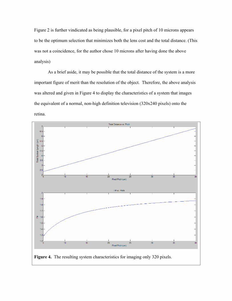
Figure 2 is further vindicated as being plausible, for a pixel pitch of 10 microns appears
to be the optimum selection that minimizes both the lens cost and the total distance. (This
was not a coincidence, for the author chose 10 microns after having done the above
analysis)
As a brief aside, it may be possible that the total distance of the system is a more
important figure of merit than the resolution of the object. Therefore, the above analysis
was altered and given in Figure 4 to display the characteristics of a system that images
the equivalent of a normal, non-high definition television (320x240 pixels) onto the
retina.
Figure 4. The resulting system characteristics for imaging only 320 pixels.

It is interesting to note that while the object height has decreased, the F# graph is
identical to the one in Figure 3, for as the object height and required lens diameter
decrease, the focal length decreases at the same rate. However, the total distance has
decreased by the fractional decrease in resolution since the focal length of lens 1 linearly
depends on the object height. Since the behavior of both graphs has not altered, the
optimum pixel pitch is still 10 microns, but the total distance is now 2.98cm. Therefore,
these results show that a desired total distance can be attained even with a set pixel pitch
and F# by changing the object resolution.
Gaussian Design
The next step in creating a truly usable design is to replace the ideal lenses being
used thus far with thick lenses that can be purchased and actually used. Since it is more
cost effective to find a commonly manufactured lens than to custom order a large
quantity of specialized lenses, the Newport lens catalogue was perused. The common
lens closest to the specifications of the external lens was then selected, and its reported
specifications are given below in Figure 5.
Figure 5. Selected lens for use in the proposed system.
EFL, effective focal length, is the distance from either principle plane to the focal plane.
FFL, front focal length, and BFL, back focal length, are the distances from the front/back
lens surface to the front/back focal plane. Tc and Te are the center thickness and edge

thickness of the lens, respectively. Therefore, EFL-FFL is the distance between the front
lens surface and a principle plane, and since this quantity is zero, the first principle plane
must be on the lens’ surface. Likewise, the back principle plane is 3mm in front of the
back lens surface. (This is what the specification P2 means) Therefore, the front lens
surface should be placed at the intended location of the ideal external lens given in Figure
2, and the lens will effectively thicken the design by Tc-3=1.5mm. When introducing
principle planes into the second lens, (the eye) one finds that the cornea is actually
1.47mm in front of the first principle plane. Therefore, the total distance of the device
should be measured from the cornea edge and not from the ideal lens as presupposed,
which shortens the system length by 1.47mm. The separation between the two principle
planes in the eye does not thicken the system length, for the separation is within the
eyeball. The end result of using these real lenses is given in the diagram below, where
the new total system distance is barely changed to 9.22+.15-.147=9.223cm.

Figure 6. Thickened design with principle planes for lens 1 and eye.
Finite Design
The pupil for a relaxed eye is 1.85mm behind the eye lens and normally ranges
between 3mm and 7mm in diameter. It is reasonable to presume that the eye pupil will
never shrink to less than 3mm in diameter with any optical system present since the light
source behind the LCD object would be adjusted to give a comfortable level of intensity.
(Moreover, the system in question will not be designed to operate properly if the user
looks directly at the sun, for instance) The eye pupil will become the aperture and field
stop with such a small diameter; therefore, these limitations will be quantified.

First, the field stop will be determined from the pupil diameter. By propagating a
ray backwards that has zero angle and barely grazes the eye pupil, the largest object size
(i.e. field stop) will be determined. Although the field stop can usually be determined by
using the imaging condition through both lenses, the image is at the focal plane, leading
to imaging infinities. Since the author is interested in the size of the field stop at the
predetermined object location, a numerical backpropagation from the eye pupil is
performed instead, and the results are shown with the blue ray in Figure 7.
Figure 7. Blue ray giving original object height after grazing eye pupil at zero angle.
The maximum field stop in this worst-pupil case is 3.53mm or about a third of the total
object size.

Next, the pupil as the aperture stop will be considered. The maximum angle
given from the NA of the system hits the pupil at 2.495mm off axis, meaning that a pupil
of a 5mm diameter or larger will gather all of the resolution. Since the worst case is
when the pupil is 3mm in diameter, the pupil will only gather 60% of the resolution,
making the object’s 2000 pixels effectively 1200 resolvable pixels at the image.
Both of these results may seem disastrous, for the dynamics of the eye pupil are
not a free parameter in the design. The external lens’ diameter was lowered in order to be
a common, purchasable lens, which could be rectified with a custom lens, but since the
pupil is the limiting aperture, such would be a fruitless gesture. However, there are two
reasons why these results can be gracefully accepted and allowed. First, the eye pupil
creates the same conundrum when it is observing a big screen TV at an acceptable
distance, meaning that rectifying this problem is not necessary in order to replicate a TV
screen image. Second, the reason why TVs that are larger than the field stops with
resolutions higher than the pupil can observe exist are due to the eye’s unique anatomy.
The eye’s photo detector density is 100 times larger in the 1 square millimeter area that is
on axis than the rest of the retina, making the on axis image the most noticeable part of
the original object. Anyone with a functioning eye can observe this by noting that an
object’s clarity is far less when it is off the eye’s axis. Since the fovea (highest detection
density spot in the eye) subtends only 1.3 degrees of visual angle, it is clear that the pupil
does not limit the resolving capability of the on-axis detectors. Moreover, the NA of the
system easily enters the pupil when it originates from the axis. Therefore, the eye will
not discern any difference in the resolution of the off-axis parts of the object and will

detect the full resolution of the on-axis part of the object, while an artificial uniformly
distributed detector array would be more severely limited by such a small pupil.
Final Design
Now that a design with a real, thick lens has been incorporated into the design, the
final step is to translate the design into a real-world device that can be mounted on the
head in convenient and portable fashion. Since the design requires only a single lens and
is roughly 9.2cm in length, a very large number of possible setups could be determined.
The following is the author’s proposed implementation.
A small box is attached to the top frame of a pair of partially reflective glasses.
The video source lies inside the box on the end furthest away from the user’s forehead.
The light is then reflected onto the external lens, which then passes outside of the box and
is reflected off of the glasses into the eye. Assuming reflection angles of 45 degrees in
order to minimize the box’s space, the resulting setup is given in Figure 8.

Figure 8. Proposed optical setup where the purple box is the video source of unspecified
thickness, the red lines are mirrors, the brown lines are lenses, and the two blue lines
represent light rays from either end of the video source.
The reflecting surface outside of the box is almost 3cm, which is approximately the
average size of a sunglass lens. Moreover the box mounted above the glasses is small
enough to comfortably rest against the user’s forehead with little or no discomfort. Both
of these results achieve the aim of this report in terms of size and portability.
Another possible implementation is possible in order to ease the requirements of
the external lens. In Figure 9, a prism is attached to the bottom of the box housing in
order to ease angling constraints, as well as aid in the magnifying power of the system.
However, this approach will not be quantified since a duplicate analysis would be
required, and this is merely a suggestion if further investigation yields a desire to use a
less powerful external lens.

Figure 9. Setup augmented with a prism.
If design constraints required a smaller system, it could be possible to replace the
mirror and the lens inside the box with a single curved mirror. However, investigation of
common curved lenses indicates that the resulting F# would be far too high to be
desirable. Furthermore, the cost of a single common curved mirror equals the cost of 5 of
the selected lens or 7 flat mirrors, which reserves such a solution for only a more costly
“spin-off” of this device
(http://www.newport.com/store/product.aspx?lone=Optics<wo=Mirrors&id=3525&lan
g=1§ion=Pricing).
Conclusion
An optical system has been designed that is capable of imaging a small, high-
resolution video source onto the retina in the same fashion as a high-definition big screen
television. By creating a layout that is realistically small to be worn as glasses and
selecting simple components that allow for a competitive price, it has been demonstrated
that producing the optical imaging system is a plausible idea and merits further research
and development. However, the costs and implications of creating and using the video

source itself were not addressed in this report, and should be the next area of focus
concerning this device. Perhaps in the upcoming future, the populace’s relative distaste
for virtual reality headsets will be replaced by the widespread acceptance of video glasses
which will strive to replace heads up displays, televisions, and even computer monitors
everywhere.
Appendix A
Magnification of TV image on retina
Linear magnification is given as
ddM '= , (6)
where d’ is the distance from the lens to the image, and d is the distance from the object
to the lens. In the problem given, d’ is the distance from the eye lens to the retina or
1.7cm. The distance d is given as 4 meters, yielding a magnification of .00425.
.00425*(2 meters) = 8.5mm. Therefore, the TV produces an image of size 8.5mm on the
retina.
Eye power calculations for a single element imaging system
The linear magnification of a 2cm object into a 8.5mm image is .85/2=.425. As
given in equation 6, since both the magnification and the value of d’ are known, d is
calculated to be 4cm. The reader can easily prove to him/herself that bringing an object
into focus that is even 10 to 20cm away from the eye produces a maximal amount of
eyestrain. Even if eyestrain were not a factor in this problem, a human eye can not
reshape its lens enough to produce enough power to image an object 4cm away without
an external optical system. Moreover, the unaided eye is most comfortable at focusing on
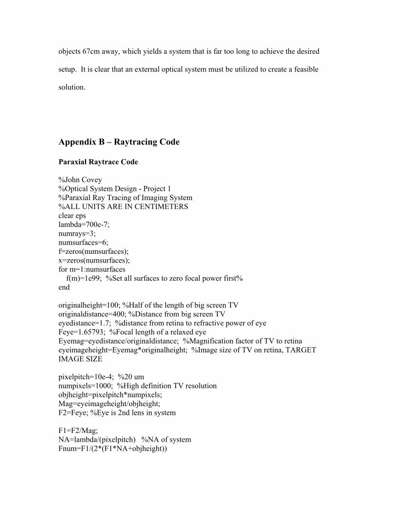
objects 67cm away, which yields a system that is far too long to achieve the desired
setup. It is clear that an external optical system must be utilized to create a feasible
solution.
Appendix B – Raytracing Code
Paraxial Raytrace Code
%John Covey %Optical System Design - Project 1 %Paraxial Ray Tracing of Imaging System %ALL UNITS ARE IN CENTIMETERS clear eps lambda=700e-7; numrays=3; numsurfaces=6; f=zeros(numsurfaces); x=zeros(numsurfaces); for m=1:numsurfaces f(m)=1e99; %Set all surfaces to zero focal power first% end originalheight=100; %Half of the length of big screen TV originaldistance=400; %Distance from big screen TV eyedistance=1.7; %distance from retina to refractive power of eye Feye=1.65793; %Focal length of a relaxed eye Eyemag=eyedistance/originaldistance; %Magnification factor of TV to retina eyeimageheight=Eyemag*originalheight; %Image size of TV on retina, TARGET IMAGE SIZE pixelpitch=10e-4; %20 um numpixels=1000; %High definition TV resolution objheight=pixelpitch*numpixels; Mag=eyeimageheight/objheight; F2=Feye; %Eye is 2nd lens in system F1=F2/Mag; NA=lambda/(pixelpitch) %NA of system Fnum=F1/(2*(F1*NA+objheight))

%x(1)=0; %Object location x(1)=(eyedistance-Feye)*(1/Mag)^2; %Object correction since focal length of eye isn't exactly equal to eye diameter f(2)=F1; %lens 1 x(2)=f(2); x(3)=x(2)+eps; f(4)=F2; x(4)=x(3)+f(2)+f(4); x(5)=x(4)+eps; x(6)=x(5)+eyedistance; h(1,1)=objheight; %Object Height h(1,3)=h(1,1); u(1,1)=0; u(1,2)=NA; u(1,3)=u(1,2); %h(1,2)=-u(1,2)*f(2); h(1,2)=-NA*(F1-x(1)); for n=1:numrays for m=1:numsurfaces-1 M=[1,x(m+1)-x(m);-1/f(m),1]*[h(m,n);u(m,n)]; h(m+1,n)=M(1); u(m+1,n)=M(2); end end figure plot(x,h(:,1),x,h(:,2),x,h(:,3)) Pixel Pitch Behavior Code %John Covey %Optical System Design - Project 1 %Impact of variation of Pixel Pitch in System %UNITS IN CM lambda=700e-7; %Red light originalheight=100; %Half of the length of big screen TV originaldistance=400; %Distance from big screen TV eyedistance=1.7; Feye=eyedistance; %Focal length and distance from retina to refractive power of eye Eyemag=eyedistance/originaldistance; %Magnification factor of TV to retina eyeimageheight=Eyemag*originalheight; %Image size of TV on retina, TARGET IMAGE SIZE pixelpitch=5e-4:1e-4:40e-4; %20 um numpixels=160; %High definition TV resolution

objheight=pixelpitch*numpixels; Mag=eyeimageheight./objheight; F2=Feye; %Eye is 2nd lens in system F1=F2./Mag; NA=lambda./(pixelpitch); %NA of system Fnum=F1./(2.*((F1.*NA)+objheight)); distance=2.*F1+F2; subplot(2,1,1) plot(pixelpitch.*10000,distance) title('Total Distance vs. Pitch') xlabel('Pixel Pitch (um)') ylabel('Total System Length (cm)') subplot(2,1,2) plot(pixelpitch.*10000,Fnum) title('F# vs. Pitch') xlabel('Pixel Pitch (um)') ylabel('F#') Aperture/Field Stop Ray Tracing %John Covey %Optical System Design - Project 1 %Aperture/Field stop determination %UNITS IN CM clear eps lambda=700e-7; numrays=3; numsurfaces=6; f=zeros(numsurfaces); x=zeros(numsurfaces); for m=1:numsurfaces f(m)=1e99; %Set all surfaces to zero focal power first%% end originalheight=100; %Half of the length of big screen TV originaldistance=400; %Distance from big screen TV eyedistance=1.7; %distance from retina to refractive power of eye Feye=1.65793; %Focal length of a relaxed eye Eyemag=eyedistance/originaldistance; %Magnification factor of TV to retina eyeimageheight=Eyemag*originalheight; %Image size of TV on retina, TARGET IMAGE SIZE pixelpitch=10e-4; %20 um numpixels=1000; %High definition TV resolution objheight=pixelpitch*numpixels;

Mag=eyeimageheight/objheight; F2=Feye; %Eye is 2nd lens in system F1=F2/Mag; NA=lambda/(pixelpitch) %NA of system Fnum=F1/(2*(F1*NA+objheight)) %x(1)=0; %Object location x(1)=(eyedistance-Feye)*(1/Mag)^2; %Object correction since focal length of eye isn't exactly equal to eye diameter f(2)=F1; %lens 1 x(2)=f(2); x(3)=x(2)+eps; f(4)=F2; x(4)=x(3)+f(2)+f(4); x(5)=x(4)+eps; x(6)=x(5)+eyedistance; h(1,1)=.15/Mag; %Object Height h(1,3)=h(1,1); u(1,1)=0; u(1,2)=NA*(.15/.2495); u(1,3)=u(1,2); %h(1,2)=-NA*(F1-x(1)); h(1,2)=0; for n=1:numrays for m=1:numsurfaces-1 M=[1,x(m+1)-x(m);-1/f(m),1]*[h(m,n);u(m,n)]; h(m+1,n)=M(1); u(m+1,n)=M(2); end end figure plot(x,h(:,1),x,h(:,2),x,h(:,3))