high speed segmental stator type 4/3 srm: design, analysis
TRANSCRIPT

J Electr Eng Technol.2017; 12(5): 1864-1871 http://doi.org/10.5370/JEET.2017.12.5.1864
1864 Copyright ⓒ The Korean Institute of Electrical Engineers
This is an Open-Access article distributed under the terms of the Creative Commons Attribution Non-Commercial License (http://creativecommons.org/ licenses/by-nc/3.0/) which permits unrestricted non-commercial use, distribution, and reproduction in any medium, provided the original work is properly cited.
High Speed Segmental Stator Type 4/3 SRM: Design, Analysis, and Experimental Verification
Pham Trung Hieu*, Dong-Hee Lee* and Jin-Woo Ahn†
Abstract – This paper presents a design of a 2-phase segmental stator type 4/3 switched reluctance motor (SRM) for air-blower application. The air-blower requires only one direction rotation, high rotor speed without torque dead-zone. In order to satisfy the requirements of the load, the rotor of the 4/3 proposed SRM is designed with wider rotor pole arc and non-uniform air-gap is applied on the rotor shape. With a special rotor structure, the motor generates a wider positive torque region and has no torque dead-zone. The stator of the proposed SRM is constructed with two segmental C-cores, and there are no magnetic connections between 2 C-cores. The flux follows in a short closed loop in each C-core and has no reversal flux in the stator. The static and dynamic characteristics of the proposed motor are analyzed by the finite element method (FEA) and Matlab-Simulink, respectively. In order to verify the design, a prototype of the proposed motor has manufactured for laboratory test. The performance of the proposed motor is verified by the simulation and experimental results.
Keywords: Switched Reluctance Motor (SRM), 4/3 SRM, Non-uniform air gap, Short flux path, Segmental stator
1. Introduction Switched reluctance motor (SRM) has simple structure
without permanent magnets (PM), commutator or windings on its rotor. The stator and rotor are laminated by magnetic steel, and the windings are wounded on the stator pole only. The robust structure of the rotor helps SRM can be used for the applications that operated in harsh environments as high temperature and high speed [1-4]. SRM cannot be operated without a power converter, and the number of power switches proportional to the number of phases with the same converter topology. Single- and 2-phase SRM are good candidates for high speed drives because of some advantages such as simplicity of structure, low cost, and low switching frequency. Single- and 2-phase SRM show some disadvantages such as high torque ripple, torque-dead zone, and no self-starting ability. Hybrid structure with PMs, torque dead-zone and self-starting problems of the single-phase SRMs can be solved [5, 6]. The use of PM makes hybrid single-phase SRM less competition compared with other machine as DC motors, and BLDC motors in high speed drive systems. In [2, 4], by modifying the structure and air-gap of the rotor, 2-phase SRMs can be operated at any rotor position without torque dead-zone and reduce the torque ripple. Because the air-gap on the rotor shape is non-uniform, so the motor has asymmetric inductance and torque characteristics with wider positive torque region. These motor type are suitable for unidirectional
applications such as air-blowers, compressors, and spindles. Non-uniform air-gap results in low average torque and low efficiency in the 2-phase SRM drives.
This paper presents a design of segmental stator 2-phase 4/3 SRM for air-blower application. In this design, the average torque of the motor is improved and the motor has self-starting ability. The proposed SRM employed four stator poles and three rotor poles. The stator is constructed in two segmental C-cores, and there are no magnetic connection between two C-cores. The flux follows in a short closed loop in each C-core and has no reversal flux in the motor. In order to verify the design, a prototype of the proposed motor has manufactured for laboratory test. The characteristics of the proposed SRM will be compared with the 4/2 SRM in [4]
2. Configuration of the Proposed 4/2 and 4/3 SRM
2.1 Structure of the 4/2 SRM [4]
Fig. 1 shows the structure of the 4/2 SRM has proposed
in [4]. In this design, the rotor shape is modified to reduce torque ripple by using combination of finite element method (FEM) and Matlab. The rotor pole optimization algorithm is illustrated in detail in the paper [4]. Single- and two-phase SRM exist the torque dead-zone in the commutation region between phases, and the motor cannot be operated at this region. A simple way to overcome this problem is that design the motor with a wider rotor pole arc, and non-uniform air-gap is applied. The stepper rotor is a
† Corresponding Author: Dept. of Mechatronics Engineering, Kyungsung University, Korea. ([email protected])
* Dept. of Mechatronics Engineering, Kyungsung University, Korea. Received: June 29, 2016; Accepted: May 19, 2017
ISSN(Print) 1975-0102ISSN(Online) 2093-7423

Pham Trung Hieu, Dong-Hee Lee and Jin-Woo Ahn
http://www.jeet.or.kr │ 1865
simple solution in this case, but there is high torque ripple at the stepper position, and an optimization algorithm has proposed in [4] to solve this problem of the stepper rotor type.
Fig. 2 shows the flux distribution in the 4/2 SRM. At aligned position when phase A excited, the rotor is overlapped with the stator of phase B that make sure the motor has overlap torque and self-starting ability. The flux path of the 4/2 SRM is illustrated in Fig. 3. The flux follows in a long closed loop in whole stator.
2.2 Characteristics of the 4/2 SRM
The static characteristics of the 4/2 SRM is analyzed by
a 2D FEM software. Fig. 4 shows the torque waveform of the 4/2 SRM at the optimized torque 0.2[Nm]. There is no
overshoot torque at the flat top and has no torque dead-zone in the commutation region. As shown in Fig. 5, torque ripple increases when load increased. The optimization effects only at the optimized torque, and it is sensitive with the operating conditions and motor structure. Non-uniform air gap makes the motor has low average torque and low efficiency. The average torque can be increased by increase the stator pole arc and reduce the non-uniform air gap region. With a given dimension, when the stator pole arc is increased that results in small winding area, and it not enough space for windings.
2.3 Structure of the proposed SRM
The proposed SRM employed four stator poles and three
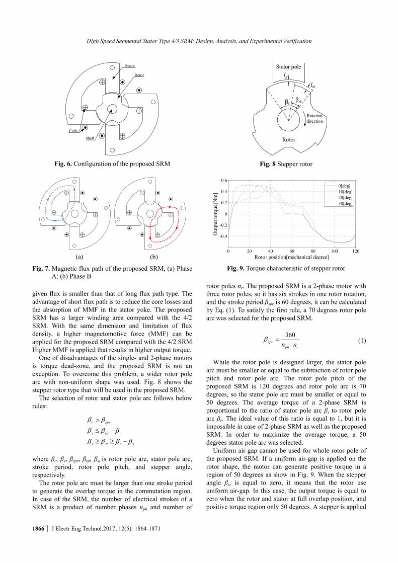
rotor poles. The stator has a special structure with two segmental C-cores shifted with rotation of 180 degrees. There are no magnetic connection between two C-cores, and has no reversal flux in the motor. In order to increase the winding area, the stator poles is constructed in a special structure as shown in Fig. 6. The windings are wounded on two poles of the C-core in serial connection. The flux path is formed in a short closed loop in C-core when respective phase excited. Short flux path results in lower reluctance and lower core losses compared with long flux path one.
Fig. 7 shows the flux path in the proposed SRM. A motor with the shorter flux path technique has lower reluctance, it means that the MMF required to produce a
Stator RotorShaft Coils
Fig. 1. 4/2 SRM
(a) Full aligned position (b) Flull unaliged position
Fig. 2. Flux distribution in the 4/2 SRM
Fig. 3. Flux path in the 4/2 SRM
0 20 40 60 80 100 120 140 160 180
-0.4
-0.2
0
0.2
0.4
Rotor position[mechanical degree]
Out
put t
orqu
e[N
m]
Phase A Phase B Continuous torque
Fig. 4. Torque waveform of the 4/2 SRM
Fig. 5. Torque profiles of the 4/2 SRM
High Speed Segmental Stator Type 4/3 SRM: Design, Analysis, and Experimental Verification
1866 │ J Electr Eng Technol.2017; 12(5): 1864-1871
given flux is smaller than that of long flux path type. The advantage of short flux path is to reduce the core losses and the absorption of MMF in the stator yoke. The proposed SRM has a larger winding area compared with the 4/2 SRM. With the same dimension and limitation of flux density, a higher magnetomotive force (MMF) can be applied for the proposed SRM compared with the 4/2 SRM. Higher MMF is applied that results in higher output torque.
One of disadvantages of the single- and 2-phase motors is torque dead-zone, and the proposed SRM is not an exception. To overcome this problem, a wider rotor pole arc with non-uniform shape was used. Fig. 8 shows the stepper rotor type that will be used in the proposed SRM.
The selection of rotor and stator pole arc follows below rules:
r spr
s rp r
s st r s
where βr, βs, βspr, βrp, βst is rotor pole arc, stator pole arc, stroke period, rotor pole pitch, and stepper angle, respectively.
The rotor pole arc must be larger than one stroke period to generate the overlap torque in the commutation region. In case of the SRM, the number of electrical strokes of a SRM is a product of number phases nph and number of
rotor poles nr. The proposed SRM is a 2-phase motor with three rotor poles, so it has six strokes in one rotor rotation, and the stroke period βspr is 60 degrees, it can be calculated by Eq. (1). To satisfy the first rule, a 70 degrees rotor pole arc was selected for the proposed SRM.
360
sprph rn n
(1)
While the rotor pole is designed larger, the stator pole
arc must be smaller or equal to the subtraction of rotor pole pitch and rotor pole arc. The rotor pole pitch of the proposed SRM is 120 degrees and rotor pole arc is 70 degrees, so the stator pole arc must be smaller or equal to 50 degrees. The average torque of a 2-phase SRM is proportional to the ratio of stator pole arc βs to rotor pole arc βr. The ideal value of this ratio is equal to 1, but it is impossible in case of 2-phase SRM as well as the proposed SRM. In order to maximize the average torque, a 50 degrees stator pole arc was selected.
Uniform air-gap cannot be used for whole rotor pole of the proposed SRM. If a uniform air-gap is applied on the rotor shape, the motor can generate positive torque in a region of 50 degrees as show in Fig. 9. When the stepper angle βst is equal to zero, it means that the rotor use uniform air-gap. In this case, the output torque is equal to zero when the rotor and stator at full overlap position, and positive torque region only 50 degrees. A stepper is applied
Stator
Rotor
Shaft
Coils
Fig. 6. Configuration of the proposed SRM
(a) (b)
Fig. 7. Magnetic flux path of the proposed SRM, (a) Phase A; (b) Phase B
βst βr
lg
lst
Stator pole
Rotor
Rotation direction
Fig. 8 Stepper rotor
0 20 40 60 80 100 120
-0.4
-0.2
0
0.2
0.4
0.6
Rotor position[mechanical degree]
Out
put t
orqu
e[N
m]
0[deg]10[deg]20[deg]30[deg]
Fig. 9. Torque characteristic of stepper rotor

Pham Trung Hieu, Dong-Hee Lee and Jin-Woo Ahn
http://www.jeet.or.kr │ 1867
on a part of the rotor pole to extend the positive torque region as shown in Fig. 8. The output torque of the 4/3 SRM with different stepper angle is shown in Fig. 9. In this simulation, the air-gap length lg is 0.25mm and the stepper air-gap length lst is 0.25mm. The phase winding consist of two coils, each coil has 50 turns, and connected in serial. The phase winding is excited by a DC current 10A. As shown in Fig. 9, when increase the stepper angle, the positive region also increases. But the stepper angle has to satisfy the rule number 3. The stepper angle must be equal or greater than the value of the subtraction of rotor pole arc and stator pole arc, and the maximum value of stepper angle is equal to stator pole arc.
Although increasing of the stepper angle helps the motor generates a wider positive torque region, but it also results in lower average torque. Fig. 10 shows the average torque of the proposed SRM when changing the stepper angle. To maximize the average torque, the stepper angle is selected as small as possible. In case of the proposed SRM, a 22 degrees stepper angle was selected.
Fig. 11 shows the output torque of the proposed SRM when changing the stepper air-gap length lst. When increase the lst, the starting torque is reduced, and the ended torque is increased. High starting torque helps the motor can be started easily, but the ended torque cannot be zero.
Fig. 12 shows the rotor shape of the proposed SRM. The non-uniform air-gap is 22 degrees of the total 70 degrees of the rotor pole. The positive torque is generated during the
rising slope of the inductance, it is given in Eq. (2).
d
idLiTe
),(
2
1 2 (2)
where Te is the electromagnetic torque, i is the excited current, and L(θ,i) is the inductance dependent on the rotor position and phase current.
The inductance in the motor depends on the air-gap length and the overlap area between rotor and stator poles. When the rotor and stator pole are at first overlap region, increasing overlap area results in increasing inductance. Otherwise, when the rotor is at full aligned position, the overlap area is constant, reducing of average air-gap between rotor and stator pole results increasing inductance. So, the motor can produce positive torque during 70 degrees of rotor poles.
Based on the stepper rotor type, the air-gap in the stepper part is modified for torque smoothing. Non-uniform air-gap has no significant effect on average torque. Fig. 13 shows the output torque of the 4/3 SRM with different rotor type.
3. Characteristics of the Proposed SRM The static characteristics of the proposed motor is
analyzed by using a 2D FEA. By using the FEA software, the characteristic of the flux distribution that influences the performance and characteristic of the motor is analyzed. As shown in Fig. 14, the magnetic flux only flows through the respective excited C-core. Actually, small amount of flux
0 10 20 30 40 50 60 70
0.2
0.25
0.3
0.35
Stepper angle[mechanical degree]
Ave
rage
torq
ue[N
m]
Fig. 10. Average torque vs. stepper angle of the proposed SRM
0 20 40 60 80 100 120
-0.4
-0.2
0
0.2
0.4
0.6
Rotor position[mechanical degree]
Out
put t
orqu
e[N
m]
0[mm]0.2[mm]0.4[mm]0.6[mm]
Fig. 11. Output torque vs. stepper air-gap length of the 4/3 SRM
Rotation direction
700220
Uniform air gap Non-uniform air gap
Rotor pole
Fig. 12. Rotor shape
0 20 40 60 80 100 120-0.8
-0.6
-0.4
-0.2
0
0.2
0.4
0.6
Rotor position[mechanical degree]
Out
put t
orqu
e[N
m]
Non-uniform air gapStepper air gap
Fig. 13. Comparison torque of non-uniform and stepper air gap type

High Speed Segmental Stator Type 4/3 SRM: Design, Analysis, and Experimental Verification
1868 │ J Electr Eng Technol.2017; 12(5): 1864-1871
flows through the other, but it is not appreciable. Flux density in the motor is kept lower 1.8T.
Torque is one of the important parameters. The designers try to increases the output torque. The higher torque density that means the motor has compact size and low cost. Compared with the others motor which have a uniform rotor shape, the proposed motor has lower torque production. Fig. 10 shows the torque waveform of the proposed SRM at rated current. As shown, the overlap torque is about 10 degrees. This overlap torque make sure the motor can be operated at any rotor position without the torque dead-zone and has self-starting ability.
Fig. 16 and 17 show the torque and inductance profiles of the proposed SRM, respectively. The 4/2 and proposed SRM have asymmetric inductance and torque charac-teristics with wider positive region. Because of these characteristics, the 4/2 and proposed SRM are suitable for unidirectional rotation application.
Fig. 18 shows the comparison average torque of the 4/2 SRM and the proposed SRM. With the same MMF, the
proposed SRM generates higher average torque compared with the 4/2 SRM. When a MMF 450[AT]/pole is applied for both motors, the average torque of the 4/2 SRM is 0.198[Nm] while that of the proposed SRM is 0.279 (40% higher). Higher output torque makes a motor has a compact size and low cost.
Fig. 19 shows the performance comparison of the proposed and 4/2 SRM. Two motors are designed with the same dimensions, and the specifications of the 4/2
(a) Unaligned position
(b) Phase A excited (c) Phase B excited
Fig. 14. Flux distribution in the proposed SRM
0 20 40 60 80 100 120-0.4
-0.2
0
0.2
0.4
Rotor position [mechanical degree]
Out
put t
orqu
e [N
m]
Phase A Phase B Continuous torque
Fig. 15. Torque profiles
0 20 40 60 80 100 120
-1
-0.8
-0.6
-0.4
-0.2
0
0.2
0.4
0.6
0.8
1
Rotor position[mechanical degree]
Out
put t
orqu
e[N
m]
2[A]4[A]6[A]8[A]10[A]12[A]14[A]16[A]
Fig. 16. Torque profiles
0 20 40 60 80 100 120
2
4
6
8
10
12x 10
-3
Rotor position[mechanical degree]
Indu
ctan
ce[H
]
2[A]4[A]6[A]8[A]10[A]12[A]14[A]16[A]
Fig. 17. Inductance profiles
0 200 400 600 800 10000
0.2
0.4
0.6
0.8
MMF[AT]
Ave
rage
torq
ue[N
m]
4/3 SRM 4/2 SRM
Fig. 18. Comparison torque of the 4/2 SRM and the proposed 4/3 SRM

Pham Trung Hieu, Dong-Hee Lee and Jin-Woo Ahn
http://www.jeet.or.kr │ 1869
and proposed 4/3 SRM are given in Table 1. There are 8 parameters selected for performance comparing. Because of the special structure, the proposed SRM has larger space for winding, and it can generate higher torque as well as output power compared with the 4/2 SRM. The proposed SRM is better in average torque, peak torque, max power, power-to-weight ratio, and efficiency compared with the 4/2 SRM. While the 4/2 SRM is better in max speed and lower torque ripple compared with the proposed SRM. The proposed SRM is characterized by high torque and efficiency. It is suitable for the applications that require high torque density like rotary hammer, hitter while the torque ripple is not a serious problem. The 4/2 SRM is good for very high speed application like air-blower, compressor.
Fig. 20 shows the prototype of the proposed SRM. The
dimensions of the prototypes are given in Table 1. The manufacturing of the proposed SRM is more difficult compared with the 4/2 SRM. Because the stator is separated into two cores without the steel connection. The stator cores are fixed in the cover by four screws. There are some mechanical errors that make the air-gap not the same at any positions around the rotor. So the assembling of the motor has to be done carefully and exactly.
Fig. 21 and 22 show the measured and FEM analysis inductance and torque vs. rotor position of the proposed SRM, respectively. As shown in this figure, the measured
Table 1. Specifications of the 4/2 and proposed 4/3 SRM
Parameters 4/2 SRM 4/3 SRM Unit Outer diameter 90 90 mm Bore diameter 32 32 mm Stack length 33 33 mm
Rotor pole arc 70 102 degree Stator pole arc 45-50 48 degree
Air gap 0.25-0.6 0.25-0.65 mm Rated torque 0.2 0.2 Nm
Operating speed 10,000 10,000 rpm Operating power 210 210 W
Fig. 19. Performance comparison of the proposed and 4/2 SRM
(a) (b) (c)
Fig. 20. Prototype of the proposed SRM: (a) Rotor; (b) Stator; (c) Full assembly of the proposed SRM
Table 2. Performance comparison of the 4/2 and proposed SRM
4/2 SRM 4/3 SRM Parameters
Simulation Measurement Simulation MeasurementSpeed[rpm] 10,000 10,000 10,000 10,000 Torque[Nm] 0.2 0.2 0.2 0.2 Input power
[W] 265.3 302.9 258.8 274.5
Output power[W]
209.6 209.6 209.6 209.6
Efficiency 79 69.2 81 76.4
0 20 40 60 80 100 1201
2
3
4
5
6
7
8
9
10x 10
-3
Rotor position [mechanical degree]
Indu
ctan
ce [
H]
FEM Measured
Fig. 21. Measured and FEM analysis inductance vs. rotor position of the proposed SRM
0 20 40 60 80 100 120-0.4
-0.3
-0.2
-0.1
0
0.1
0.2
0.3
0.4
Rotor position [mechanical degree]
Out
put t
orqu
e [N
m]
FEM Measured
Fig. 22. Measured and FEM analysis torque vs. rotor position of the proposed SRM

High Speed Segmental Stator Type 4/3 SRM: Design, Analysis, and Experimental Verification
1870 │ J Electr Eng Technol.2017; 12(5): 1864-1871
flux linkage well match to that of predicted by FEM. The error for unaligned and aligned position is less than 8%.
Fig. 23 shows the experimental setup of the proposed SRM drive system. The load is supplied by the adjustable dynamometer. The output power is measured by high-speed dynamometer 2WB43, and the input power is
measured by the power analyzer PPA2530. The prototyped is tested with dynamometer, the
experimental results at 10,000rpm and 13,000rpm are shown in Fig. 24 and 25, respectively. Table 2 shows the performance comparison of the 4/2 and the proposed SRM. The measured efficiency of the proposed SRM is 10.4[%] higher than that of the 4/2 SRM. The differences between simulation and measurement are from mechanical losses and windage losses that were not considered in the simulation model. Fig. 26 shows the performance vs. rotor speed of the 4/2 SRM and the proposed SRM.
5. Conclusions This paper presents design and analysis of a high-speed
segmental stator type 4/3 SRM. In order to produce a continuous output torque, the positive torque region is extended with an asymmetric inductance characteristic. The proposed SRM has extended positive torque region and the air gap is non-uniform with a torque over-lap region between phases. The proposed motor is suitable for unidirectional rotation application. A prototype of the proposed motor has manufactured and tested to verify the design. The proposed SRM has shown a better performance compared with the 4/2 SRM in [4].
Acknowledgement This work was supported by the Human Resources
Program in Energy Technology of the Korea Institute of Energy Technology Evaluation and Planning (KETEP) granted financial resource from the Ministry of Trade, Industry & Energy, Republic of Korea. (No. 20 1640 10200940)
References
[1] J. Dang, J. Rhett Mayor, S. A. Semidey, R. G. Harley,
Fig. 23. Experimental setup
Fig. 24. Experimental result of the proposed SRM with load torque 0.2[Nm] at 10,000[rpm]
Fig. 25. Experimental result of the proposed SRM with load torque 0.2[Nm] at 13,000[rpm]
4 5 6 7 8 9 10 1140
50
60
70
80
90
Rotor speed [krpm]
Eff
icie
ncy
[%]
4/3 SRM 4/2 SRM
Fig. 26. Performance vs. rotor speed of the 4/2 SRM and the proposed SRM

Pham Trung Hieu, Dong-Hee Lee and Jin-Woo Ahn
http://www.jeet.or.kr │ 1871
T. G. Habetler, and J. A. Restrepo, “Practical Considerations for the Design and Construction of a High-Speed SRM With a Flux-Bridge Rotor,” Industry Applications, IEEE Transactions on, vol. 51, pp. 4515-4520, 2015.
[2] Z. Haijun, X. Weijie, W. Shuhong, H. Youpeng, W. Guolin, and Z. Jianguo, “Optimum Design of Rotor for High-Speed Switched Reluctance Motor Using Level Set Method,” Magnetics, IEEE Transactions on, vol. 50, pp. 765-768, 2014.
[3] D. Wen, L. Ling, and L. Jianyong, “Design and control of a high-speed switched reluctance machine with conical magnetic bearings for aircraft appli-cation,” Electric Power Applications, IET, vol. 7, pp. 179-190, 2013.
[4] L. Dong-Hee, P. Trung Hieu, and A. Jin-Woo, “Design and Operation Characteristics of Four-Two Pole High-Speed SRM for Torque Ripple Reduction,” Industrial Electronics, IEEE Transactions on, vol. 60, pp. 3637-3643, 2013.
[5] K. Lu, P. O. Rasmussen, S. J. Watkins, and F. Blaabjerg, “A New Low-Cost Hybrid Switched Reluctance Motor for Adjustable-Speed Pump Applications,” IEEE Transactions on Industry Applications, vol. 47, pp. 314-321, 2011.
[6] L. Kaiyuan, U. Jakobsen, and P. O. Rasmussen, “Single-Phase Hybrid Switched Reluctance Motor for Low-Power Low-Cost Applications,” IEEE Trans-actions on Magnetics, vol. 47, pp. 3288-3291, 2011.
Pham Trung Hieu was born in Binh Phuoc, Vietnam, in 1986. He received the B.S. degree in electrical engin-eering from Binh Duong University, Binh Duong, Vietnam, in 2010, and the M.S. and Ph.D degrees in mechatro-nics engineering from Kyunsung University, Busan, Korea, in 2013 and
2016, respectively. He is currently with Kyungsung University, Busan, Korea, as an assistant professor in the Department of Mechatronics Engineering. His research interests include design and control of switched reluctance motors and power electronics.
Dong-Hee Lee was born on Nov.11, 1970. He received B.S., M.S., and Ph.D degrees in Electrical Engineering from Pusan National University, Busan, Korea, in 1996, 1998 and 2001, re-spectively. He worked as a Senior Researcher of Servo R&D Team at OTIS-LG, from 2002 to 2005. He has
been with Kyungsung University, Busan, Korea, as a
professor in the Department of Mechatronics Engineering since 2005. In 2012, he was a visiting professor in University of Wiconsin-Madison, WI, USA. He is an Associate Editor of the Journal of Power Electronics. His research interests include power electronics and motor control systems.
Jin-Woo Ahn was born in Busan, Korea, in 1958. He received his B.S., M.S., and Ph.D. degrees in Electrical Engineering from Pusan National University, Busan, Korea, in 1984, 1986 and 1992, respectively. He has been with Kyungsung University, Busan, Korea, as a professor in the
Department of Mechatronics Engineering since 1992. He is Vice President of KIEE and the director of the Smart Mechatronics Advanced Research and Technology Institute and Senior Easy Life RIS Center. He is the author of five books including SRM, the author of more than 200 papers and has more than 30 patents. His current research interests are advanced motor drive systems and electric vehicle drives. He also received many awards from IEEE, KIEE and KIPE and including Order of Science and Technology Merit from the President of the Republic of Korea for his numerous contributions for the electrical engineering. He served as a Conference Chairman of International Con-ference on Electric Machines and Systems2013(ICEMS 2013), and of International Conference on Industrial Technology 2014(IEEE/ICIT2014) and serving as a Conference Chairman of IEEE Transportation Electri-fication Conference and Expo 2016 Busan(ITEC2016 Busan). He is a Fellow of the Korean Institute of Electrical Engineers, a member of the Korean Institute of Power Electronics and a Senior member of the IEEE.