high-tech composites to ancient metals - isis neutron source · high-tech composites to ancient...
TRANSCRIPT

ISSN:1369 7021 © Elsevier Ltd 2009
High-tech composites to ancient metals
A variety of strain measurement techniques have evolved over
the decades and are widely employed in experimental studies of
deformation behaviour of materials and structures. The aim of
strain measurement is to characterise the response to applied
loads, particularly those corresponding to in-service loading, and
to observe the response of objects so as to predict the integrity of
various designs. This is the principal significance of strain analysis
for structural design1.
Most strain measurement methods are only capable of measuring
total strain increments. This is due to the fact that strain measurement
Neutron diffraction methods offer a direct measure of the elastic component of strain deep within crystalline materials through precise characterisation of the interplanar crystal lattice spacing. The unique non-destructive nature of this measurement technique is particularly beneficial in the context of engineering design and archaeological materials science, since it allows the evaluation of a variety of structural and deformational parameters inside real components without material removal, or at worst with minimal interference. We review a wide range of recent experimental studies using the Engin-X materials engineering instrument at the ISIS neutron source and show how the technique provides the basis for developing improved insight into materials of great importance to applications and industry.
S.Y. Zhang1, E. Godfrey1, W. Kockelmann1, A. Paradowska1, M. J. Bull1, A. M. Korsunsky2, B. Abbey2, P. Xu3,4, Y. Tomota3, D. Liljedahl5, O. Zanellato5, M. Fitzpatrick5, M. R. Daymond6, R. M. Toda6, R. A. Holt6, J.Kelleher7, S. Siano8, J. Santisteban9
1ISIS Pulsed Neutron and Muon Source, Science and Technology Facilities Council, Rutherford Appleton Laboratory, Didcot, Oxfordshire, UK2Department of Engineering, University of Oxford, Oxford, UK3Graduate School of Science and Engineering, Ibaraki University, 4-12-1 Nakanarusawa, Hitachi, 316-8511, Japan;4Quantum Beam Science Directorate, Japan Atomic Energy Agency, 2-4 Shirane Shirakata, Tokai-mura, Naka-gun, Ibaraki, 319-1195, Japan5The Faculty of Mathematics, Computing and Technology, Open University, Milton Keynes, UK6Department of Mechanical and Materials Engineering, Queen’s University, Kingston, Canada7School of Materials, University of Manchester, Manchester, UK8Istituto di Fisica Applicata ‘Nello Carrara’—CNR, Via Madonna del Piano, 50019 Sesto Fiorentino, Italy9Laboratorio de Fisica de Neutrones, Centro Atomico Bariloche (R8402AGP), San Carlos de Bariloche, Argentina
NEUTRON SCATTERING SPECIAL ISSUE78

NEUTRON SCATTERING SPECIAL ISSUE 79
is usually accomplished by monitoring the change of distance between
reference points associated with markers placed on the surface or
embedded in the bulk of the material. This distance is affected by
both the elastic and inelastic parts of strain. Examples of experimental
techniques include contact methods, such as clip gauges or resistive
strain gauges2, and non-contact methods, such as photogrammetry
(measurement of displacements of visible grids on sample surface),
Moiré interferometry methods that make use of reflective gratings
deposited on sample surface3, and Digital Image Correlation (DIC)
methods4.
The particular significance of neutron and X-ray diffraction methods
is that they offer a direct method of measuring the elastic component
of strain deep within crystalline materials through the precise
characterisation of the interplanar crystal lattice spacing. In contrast
with the other methods mentioned above, diffraction uses the atomic
lattice itself as a deformation gauge. This makes the methods sensitive
only to elastic strains, since inelastic strain mechanisms do not induce
changes in interplanar lattice spacing: plasticity causes lattice plane
shear, while damage causes voiding i.e. lattice plane separation (to
distances that far exceed the original spacing).
Since stress is directly related to elastic strain, with the knowledge
of the material stiffness, diffraction thus provides a highly precise,
spatially and directionally resolved means of stress evaluation. Thanks
to its stress evaluation capability, diffraction has become an increasingly
important tool in engineering. Since most criteria of integrity and
failure in structural engineering use stress as the key parameter,
diffraction methods have become useful in predicting the durability of
components, optimising design and improving performance. The unique
non-destructive nature of this measurement technique is particularly
beneficial in the context of engineering design, since it allows the
evaluation of a variety of structural and deformational parameters
inside real components without material removal, or at worst with
minimal interference. Further, the combination of rapid data collection
with good penetration depths allows in situ, real time, spatially resolved
strain measurement (mapping) under the conditions representative
of those that might be experienced in service to investigate the
microstructure evolution behaviours involving phase transformations5,6,
bulk texture evolution7, heterogeneous elastic/plastic deformation8,22,
and dynamic recrystallization9,10.
The principle of diffraction strain measurement in polycrystalline
alloys relies on Bragg’s law that establishes the relationship between
the average interplanar lattice spacing d within the measurement
gauge volume:
2d sin θ = λ (1)
When a polycrystalline aggregate deforms elastically, the interplanar
spacing within the constituent grains changes. Within a set of planes
that have similar orientation with respect to the stress direction, the
interplanar spacing is similar between one grain and another. This grain-
set-specific strain causes observable shifts of powder-like diffraction
peaks, i.e. peaks obtained from the superposition of reflections from
multiple grains. The average values of lattice spacing extracted from
diffraction peak analysis are then compared to the spacing of the same
planes measured in an unstressed sample d0. Average elastic strain can
be found from deformed lattice spacing d by
ε = (d – d0
d0) = Δ d0
d (2)
Engin-X at ISISThe Engin-X instrument at ISIS is a world leading neutron
diffractometer purpose-built for stress evaluation in the context of
materials engineering and research. Engin-X is very popular and used
extensively by both engineers and materials scientists. Measurements
are carried out in collaborative experiments between universities,
industry and ISIS to address a wide range of engineering problems:
new welding technologies for airframe manufacturing; fatigue crack
initiation and propagation in composite materials; thermal cycling of
materials used in the power generation industry; and the development
of strain measurement standards.
Because the method is non-destructive and Engin-X is able to
accommodate large intact objects, archaeological materials scientists,
conservators, and technical art historians also find that the instrument
provides them with data on metal artefacts that they could not
acquire by conventional means. The alternative, traditional methods of
microstructure determination require invasive sampling. Because of this,
strain and tensile tests for example have in the past very rarely been
done on archaeological and historic objects.
A sample mounting stage allows samples weighing up to one tonne
to be accurately positioned within the measurement point with the
accuracy better than 10 μm. Moving and rotating the sample within
the neutron beam allows spatial and directional maps of strain to be
built up. With the large sample mounting space, Engin-X provides the
flexibility for the users to bring their own ancillary devices, such as
welding rigs to perform real-time strain measurements during joining.
An in situ mountable servo-hydraulic stress rig can apply up to 100 kN
tensile or compressive cyclic loads. The rig is equipped with a furnace
and a cryogenic chamber that allow the sample to be maintained at
temperatures from -200 °C to 1100 °C within normal atmosphere or
under inert gas. The automation of experimental setup for complex
shape samples can be addressed via the use of the coordinate
measurement machine (CMM), laser scanning inspection arms, a
robotic arm and the virtual laboratory, SScanSS11.
With regard to Heritage Science applications, diffraction
measurements without any sample environment can be carried out on
the actual artefact itself, although it is important to have comparative
High-tech composites to ancient metals REVIEW

NEUTRON SCATTERING SPECIAL ISSUE80
replica measurements too, as all early metal objects are effectively
‘unknown’ samples, each made individually in the days before industrial
standardisation. The chemical composition of the metal object has to
be characterised first, then replicas produced of the same composition
and dimensions (in particular, thickness). The replicas must be formed
in the way(s) that the original was likely to be produced, e.g. casting,
hammering, fire-welding. The replicas can then be tested under different
environments. The results are compared with the data obtained from
the archaeological artefact, and interpretations can be made about how
the original object was produced. Archaeometallurgy is very often in
effect ‘reverse engineering’.
A comprehensive introduction to the neutron strain scanning
technique can be found in Hutchings et al.12. A description of the
state-of-the-art in stress measurement using neutron and synchrotron
radiation is contained in Fitzpatrick and Lodini13. More information
about Engin-X can be found in Santisteban et al.14.
Ferrite transformation in low alloy steels The deformation-induced ferrite transformation is well known as
one of the most economical ways to refine the microstructures of
modern high strength low alloy steels. The effects of deformation
temperature, strain and strain rate on dynamic ferrite transformation
during hot deformation have been investigated in the last
decade indirectly, whereby the microstructure is examined after
interrupting hot deformation at different strains, and quenching
deformed specimens15,16.
The temperature control and the hot deformation processing history
of a low alloy steel (2% Mn and 0.2% C by weight) in the as-quenched
condition are shown in Fig.1. The effect of compressive deformation
on the isothermal ferrite transformation at different temperatures is
shown in Fig. 2. If no hot deformation is applied, the ferrite volume
fraction increases gradually with increasing isothermal hold time, and
the static ferrite transformation is accelerated evidently by lowering
the holding temperature. In the case of hot deformation, it is found
that it promotes the ferrite transformation in the dual phase region
(600 °C, 640 °C, and 680 °C) as well as in the single phase austenite
region (720 °C), i.e. the occurrence of dynamic ferrite transformation
has been confirmed at different transformation temperatures. Such
changes in the dynamic ferrite transformation kinetics are believed
to be related to the carbon concentration and the volume fraction of
austenite, the transformation driving force, and the heterogeneity of
plastic deformation.
Residual stresses at cruising altitude temperatureDue to the recent marked progress in cryogenic technologies, there has
been a growing interest in material mechanical behaviour at cryogenic
temperatures. Applications include cryogenic processing of zirconium
nuclear alloys, strain sensitivity of superconducting magnet wires,
cryogenic structural steels and low temperature shape memory alloys
for space applications.
Until recently, there has been a little capability for in situ diffraction
studies of mechanical behaviour at temperatures below ambient18. A
novel cryogenic experimental device has been developed consisting of
a vacuum chamber with cooling provided by a closed cycle refrigerator
down to −200 °C in samples under applied loads of up to 100 kN19.
In order to reduce weight, modern aircraft components are increasingly
becoming hybrid structures of fibre reinforced plastics and metallic
parts20. Such structures present a lot of advantages over traditional ones.
However the difference of coefficient of thermal expansion between the
materials causes tensile residual stresses in the metallic parts. This might
affect the fatigue resistance. The stresses introduced by the thermal
mismatch will change with the temperature. At the cruising altitude of
10 000 m, the atmosphere temperature is around -50 °C, and the tensile
residual stresses are much higher than at ground level temperature. Fig. 1 Schematic illustration for the temperature control and hot deformation process.
Fig. 2 Change in ferrite amount during ferrite transformation.
REVIEW High-tech composites to ancient metals

NEUTRON SCATTERING SPECIAL ISSUE 81
Liljedahl et al.21 studied an aluminium alloy compact tension
specimen adhesively reinforced with a 2 mm titanium strap. The
adhesive was cured at 120 °C and strain measurements were carried
out at room temperature and -50 °C. Residual stresses were found to
be about 40 MPa at room temperature and about 70 MPa at -50 °C.
Residual strains in the specimen were modelled with an elastic finite
element representation of the specimen (Fig. 3) and the linear model
accurately represents the residual stresses at both temperatures.
Effect of welding procedures on residual stressWelding is an important industrial joining process, and over the years
many different “flavours” of this method have been proposed. For steel
components, a bead of molten filler metal is deposited in one or more
passes between two edges to be joined, and allowed to solidify. During this
process, the joint undergoes a complex thermomechanical cycle during
cooling. Of particular concern is the formation of tensile residual stress in
the weld, which results mainly from thermal contraction as the filler metal
cools and hardens. Where several passes are made, a pass may partially
relieve the stress in previous passes, creating a complex stress state.
Fig. 4 shows longitudinal strain in two grade 304 stainless steel
welds studied by Turski et al.23. One weld comprises five passes of weld
bead to partially fill a groove in a plate, the other weld having eight
such passes to completely fill the groove. Additionally, the welding
process was stopped and restarted twice during the fifth pass in each
sample. First was a ‘ramped’ stop-start, where the welding power was
reduced to zero over a 10 mm length, which was covered again when
the welding continued. Secondly, an ‘abrupt’ stop-start was made by
immediately stopping and later restarting the weld.
Although the 8-pass weld was thicker, it was expected that the
elastic strains would be lower than in the 5-pass weld, as the final
passes would anneal the effect of previous passes. Away from the
abrupt stop-start, this is found to be the case. The 8-pass weld
has relieved the strain at the ramped stop-start but intensified the
strain at the abrupt stop-start. This is attributed to the additional
thermomechanical cycling at this point making the material harder and
more resistant to the annealing from subsequent passes that occurs
elsewhere. The results highlight the need to rigorously specify welding
procedures. With experimental results for a given weld, these could
predict the effect of changing welding parameters such as the number
of passes or the start and stop rates.
In aeroengine manufacturing welding is used widely for the
fabrication of shell-like structures such as casings and liners, and
in the assembly of compressor and turbine components. Alongside
conventional TIG welding, laser welding and friction welding are
increasingly used, due to the ability of these methods to join dissimilar
materials and to avoid material melting, thus reducing the probability
Fig. 3 Residual stress in a compact tension specimen 3.5 mm below the bonded interface, at room temperature and flight temperature, compared with FEA modelling.
Fig. 4 Strain in the longitudinal direction of a conventional austenitic steel weld made with 5 passes and a similar weld made with 8 passes.
High-tech composites to ancient metals REVIEW

NEUTRON SCATTERING SPECIAL ISSUE82
of creating defects that may promote crack initiation and propagation.
When post-weld heat treatment is applied, there is also the possibility
of reducing the “frozen-in” residual stresses usually associated with
the bond region and the thermo-mechanically affected zone (TMAZ).
Quantification of the residual stresses is an important requirement for
improving the design and reliability of the components being joined.
A recent study provides an example of a validated experimental
stress analysis basis for structural design of aeroengine assemblies.
Strain maps in the vicinity of the bond line of an aeroengine assembly
fabricated by inertia friction welding (Fig.5a) can be interpreted
using inverse eigenstrain methodology to obtain an approximate
reconstruction of the complete residual stress state within the
sample24. The knowledge of the underlying eigenstrain distributions
then allowed the solution to be scaled up to obtain a representation
of the residual stress state in the full scale assembly.
Furthermore, subsequent stress relaxation due to creep during post-
weld heat treatment can be readily modelled using finite elements.
Fig.5b illustrates the computed residual stress state in the full scale
assembly following post-weld machining and heat treatment. The
predictions have been validated by comparison against various means
of residual stress evaluation, including diffraction and hole drilling.
Strain tomography using transmission Bragg edge measurementsA new approach to strain tomography based on energy selective
neutron imaging25 has recently been developed to analyze the residual
strain fields by the de-convolution of unknown distributions of residual
elastic strains (Fig. 6a). From a data set collected over a range of
positions and rotations, the entire strain distribution within the interior
of an object can be reconstructed. Using a model-based approach, the
unknown strain distribution is represented by a parametric model and
solved by minimisation of the mismatch between the simulated and
measured data26,27.
Vorster et al.28 quenched a cylindrical steel sample in water
to create a residual stress profile that showed significant hoop
compression near the surface, balanced by moderate tension in the
core of the sample. Residual hoop and radial strains were measured and
the residual stress state simulated by finite element modelling using
carefully characterized heat transfer conditions at the sample surface.
The residual strains are indicated by the markers in Fig.6b.
The sample was then investigated by neutron transmission
Bragg edge measurements using the setup illustrated in Fig.6a.
Bragg transmission data were analysed by strain tomography using
model-based adaptive mesh approach27. The hoop and radial strain
distributions were represented by a linear superposition of piecewise
linear basis functions, and best match was sought between the
predictions and transmission strain measurements. The residual strain
profiles reconstructed in this way (Fig.6b) show very good agreement
with the known strain fields within the sample measured previously.
Practically, the ability to reconstruct internal strain states from
transmission data is likely to open new and exciting possibilities for
residual stress analysis, since previously inaccessible configurations
may be analysed. Algorithmically, the tomographic reconstruction
principle so far has overwhelmingly been used for scalar properties,
such as density. Strain, on the other hand, is a multi-component tensor
quantity. This presents interesting challenges for the development
of this technique. It is important to ensure that the inverse problem
addressed is well-posed, either through regularization of the
formulation, or by combining transmission data with additional
information obtained by other means.
Archaeometallurgy: Manufacturing techniques in Etruscan bronze artefactsSiano et al.29 studied five archaeological copper alloy objects dated
from the 8th to the 4th centuries BC (Fig. 7) from the Marches National
Museum of Archaeology, Ancona, Italy, using neutron texture and phase
analysis on the Rotax instrument at ISIS, and microstrain measurement
on Engin-X. Microstrain measurements were performed at points on
the situla handle and on the torc, using diffraction and transmission set-
ups. The radial scans on the situla handle indicated that the preferred
orientation was the same, compatible with a cube texture associated
with the typical columnar structure that occurs perpendicularly to the
(b)(a)
Fig. 5 (a) Schematic diagram of the inertia friction welded high pressure compressor drum – drive cone (DDC) assembly. The circumferential weld line is indicated by the arrow. (b) Illustration of the residual stress map in the DDC in the final post-weld heat treated condition.
REVIEW High-tech composites to ancient metals

NEUTRON SCATTERING SPECIAL ISSUE 83
surface of the mould into which the metal is cast. Such a feature was
not present in the brazing zone of the handle, which showed random
crystal orientation.
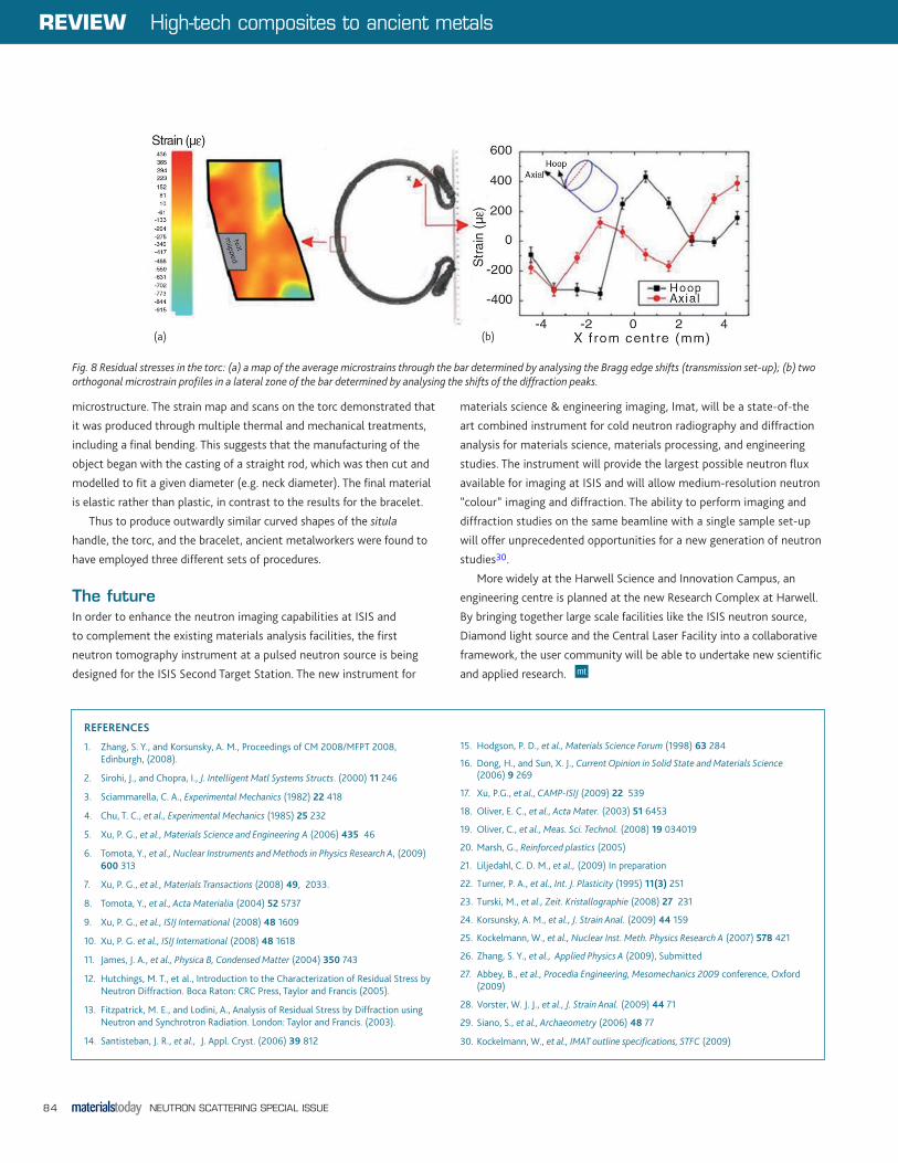
A strain map of a selected region around the middle of the
torc was calculated by analysis of the Bragg edge shifts (Fig. 8). An
inhomogeneous microstrain distribution was found, clear evidence of
residual stresses originating from cold deformation of the torc during
the final working manufacturing step. Two microstrain profiles along
orthogonal directions were also measured where the contribution
of eventual plastic deformations due to use was probably negligible.
Opposite double-phase modulations were observed along the axial and
hoop directions typical of cold bending.
Scans of the situla handle demonstrated that the object was as-cast
and did not undergo thermal homogenisation or mechanical treatment.
The development of columnar structure in the texture was favoured
by the high tin content, corresponding to a relatively low solidification
temperature. Conversely, the complex geometry of the brazing and its
fast cooling (induced by the metal contact) resulted in a disordered
Fig. 6 (a) Illustration of the experimental setup for transmission Bragg edge measurement. (b) The variation of hoop and radial strain components as a function of the radial distance. Strain measured by diffraction are shown by markers (filled circles and hollow squares); finite element modelling results are indicated by triangles. Reconstructed radial and hoop strain distributions are shown by the dashed and continuous lines.
Fig. 7 Etruscan bronze artefacts, from the Marches National Museum of Archaeology, Ancona. (a) a double handle from a situla (bucket); (b) a torc (an object-type that can be interpreted as a neck ornament or a trade-ingot); (c) & (d) bow-fibulae (dress fasteners) and; (e) a bracelet.
(a) (b)
(c) (d) (e)
(a) (b)
High-tech composites to ancient metals REVIEW
NEUTRON SCATTERING SPECIAL ISSUE84
microstructure. The strain map and scans on the torc demonstrated that
it was produced through multiple thermal and mechanical treatments,
including a final bending. This suggests that the manufacturing of the
object began with the casting of a straight rod, which was then cut and
modelled to fit a given diameter (e.g. neck diameter). The final material
is elastic rather than plastic, in contrast to the results for the bracelet.
Thus to produce outwardly similar curved shapes of the situla
handle, the torc, and the bracelet, ancient metalworkers were found to
have employed three different sets of procedures.
The futureIn order to enhance the neutron imaging capabilities at ISIS and
to complement the existing materials analysis facilities, the first
neutron tomography instrument at a pulsed neutron source is being
designed for the ISIS Second Target Station. The new instrument for
materials science & engineering imaging, Imat, will be a state-of-the
art combined instrument for cold neutron radiography and diffraction
analysis for materials science, materials processing, and engineering
studies. The instrument will provide the largest possible neutron flux
available for imaging at ISIS and will allow medium-resolution neutron
“colour” imaging and diffraction. The ability to perform imaging and
diffraction studies on the same beamline with a single sample set-up
will offer unprecedented opportunities for a new generation of neutron
studies30.
More widely at the Harwell Science and Innovation Campus, an
engineering centre is planned at the new Research Complex at Harwell.
By bringing together large scale facilities like the ISIS neutron source,
Diamond light source and the Central Laser Facility into a collaborative
framework, the user community will be able to undertake new scientific
and applied research.
REFERENCES
1. Zhang, S. Y., and Korsunsky, A. M., Proceedings of CM 2008/MFPT 2008, Edinburgh, (2008).
2. Sirohi, J., and Chopra, I., J. Intelligent Matl Systems Structs. (2000) 11 246
3. Sciammarella, C. A., Experimental Mechanics (1982) 22 418
4. Chu, T. C., et al., Experimental Mechanics (1985) 25 232
5. Xu, P. G., et al., Materials Science and Engineering A (2006) 435 46
6. Tomota, Y., et al., Nuclear Instruments and Methods in Physics Research A, (2009) 600 313
7. Xu, P. G., et al., Materials Transactions (2008) 49, 2033.
8. Tomota, Y., et al., Acta Materialia (2004) 52 5737
9. Xu, P. G., et al., ISIJ International (2008) 48 1609
10. Xu, P. G. et al., ISIJ International (2008) 48 1618
11. James, J. A., et al., Physica B, Condensed Matter (2004) 350 743
12. Hutchings, M. T., et al., Introduction to the Characterization of Residual Stress by Neutron Diffraction. Boca Raton: CRC Press, Taylor and Francis (2005).
13. Fitzpatrick, M. E., and Lodini, A., Analysis of Residual Stress by Diffraction using Neutron and Synchrotron Radiation. London: Taylor and Francis. (2003).
14. Santisteban, J. R., et al., J. Appl. Cryst. (2006) 39 812
15. Hodgson, P. D., et al., Materials Science Forum (1998) 63 284
16. Dong, H., and Sun, X. J., Current Opinion in Solid State and Materials Science (2006) 9 269
17. Xu, P.G., et al., CAMP-ISIJ (2009) 22 539
18. Oliver, E. C., et al., Acta Mater. (2003) 51 6453
19. Oliver, C., et al., Meas. Sci. Technol. (2008) 19 034019
20. Marsh, G., Reinforced plastics (2005)
21. Liljedahl, C. D. M., et al., (2009) In preparation
22. Turner, P. A., et al., Int. J. Plasticity (1995) 11(3) 251
23. Turski, M., et al., Zeit. Kristallographie (2008) 27 231
24. Korsunsky, A. M., et al., J. Strain Anal. (2009) 44 159
25. Kockelmann, W., et al., Nuclear Inst. Meth. Physics Research A (2007) 578 421
26. Zhang, S. Y., et al., Applied Physics A (2009), Submitted
27. Abbey, B., et al., Procedia Engineering, Mesomechanics 2009 conference, Oxford (2009)
28. Vorster, W. J. J., et al., J. Strain Anal. (2009) 44 71
29. Siano, S., et al., Archaeometry (2006) 48 77
30. Kockelmann, W., et al., IMAT outline specifications, STFC (2009)
Fig. 8 Residual stresses in the torc: (a) a map of the average microstrains through the bar determined by analysing the Bragg edge shifts (transmission set-up); (b) two orthogonal microstrain profiles in a lateral zone of the bar determined by analysing the shifts of the diffraction peaks.
(a) (b)
REVIEW High-tech composites to ancient metals