high-temperature air-cooled power electronics … · • ornl developed electrical topology and is...
TRANSCRIPT

NREL is a national laboratory of the U.S. Department of Energy, Office of Energy Efficiency and Renewable Energy, operated by the Alliance for Sustainable Energy, LLC.
High Temperature Air-Cooled Power Electronics Thermal Design
Scot K. Waye Principal Investigator National Renewable Energy Laboratory June 18, 2014
Project ID: APE019
This presentation does not contain any proprietary, confidential, or otherwise restricted information.

2
Overview
Phase II Start Date: FY10 Project End Date: FY14 Phase II Complete: 80%
Total Project Phase II Funding: DOE Share: $1,700K
Funding Received in FY13: $450K Funding for FY14: $450K
Timeline
Budget
Barriers
• Sapa Extrusions North America (aluminum extrusion/manufacturing)
• General Electric Global Research (previous air jet work)
• Oak Ridge National Laboratory (ORNL) – Madhu Chinthavali
Partners
• Cost – Eliminate need for secondary liquid coolant loop and associated cost and complexity
• Weight – Reduce unnecessary coolant, coolant lines, pump, and heat exchangers for lower system-level weight
• Performance – Maintain acceptable device temperatures while reducing complexity and system-level parasitic power

3
Relevance
All vehicles are air cooled
Air cooling a goal for batteries: • Simple • Direct
Just indirectly
Project Perspective
Jim Snyder, NREL Image Gallery 15165

4
State of the Art
LS 600H 2008
Camry 2007
Indirect Air Cooling via Liquid Cooling
Intermediate liquid cooling loop rejects heat to air
Direct Air Cooling Has been done before
Honda Insight (12 kW)
AC Propulsion (150 kW)
Mitsubishi SiC Inverter (50 kVA/L, 400 V output, 156 kVA)
SiC = Silicon Carbide
Relevance
Low Power
Low Power Density
Prototype: not in vehicle
NREL: John Rugh
Courtesy ORNL
DOE Advanced Vehicle Testing Activity (Idaho National Laboratory)

5
• Build and demonstrate module-level thermal (NREL) and electrical (ORNL) design (10 kW)
• Conduct detailed analysis and proof of concept at system level to show progress relative to DOE’s technical targets
Project Objective Develop air-cooled thermal management system solution that contributes to:
• Accelerating electric drive vehicle adoption • Eliminating intermediate cooling loops • Meeting DOE’s APEEM 2015 technical targets (12 kW/kg,
12 kW/L) • Supporting EV Everywhere
FY14 Project-Specific Goals
Relevance

6
Project Overview
• Air is a poor heat-transfer fluid o Low specific heat o Low density o Low conductivity • Potential parasitic power of fan • Not yet used in high power production vehicles • Filtering, fouling, fan noise
Challenges
Advantages • Rejecting heat directly to air can eliminate intermediate liquid-air loops • Attractive for high-temperature device (wide bandgap) applications • Air is benign, is not carried, and does not need to be replaced • Air is a dielectric and can contact the chip directly • No global warming potential
Relevance

7
Project Pathway This collaborative research with ORNL is on track to demonstrate an air-
cooled inverter for 30-kW continuous, 55-kW peak power
Opens path to adoption by industry as an alternative to standard liquid-cooled system that lowers weight, volume, and cost
Air-cooled inverter technology can meet 2015 DOE targets (12 kW/kg, 12 kW/L) and provides pathways to meet 2020 targets with acceptable parasitic loads
Relevance
FY14 FY12/FY13 FY11 FY10

8
Project Summary: FY11 – FY14 FY12
Q1
Q2
Q3
Q4
FY13
Q1
Q2
Q3
Q4
FY14
Q1
Q2
Q3
Q4
Heat Transfer Feasibility
Thermal and System Design and Prototyping
Module and Thermal System Demonstration
Deliverable/Milestone Go/No-Go M1 (NREL): Heat transfer feasibility study M1 (ORNL): Device-level evaluation
Heat transfer accomplished with reasonable flow and pressure loss?
M2: Build and test thermal module and initial balance of system M2: Module electrical design
Demonstrated design on track to meet targets?
M3: Demonstrate operating module and thermal system M3: Electrical inverter design and module build
Met targets for module level (10 kW)?
M2
M3
M1
FY11 M0: Proof of principle and synthetic jet vs. steady jet
Milestones

9
FY14 Tasks to Achieve Key Deliverable
2013
Oct
Nov
Dec
2014
Jan
Feb
Mar
Apr
May
Jun
Jul
Aug
Sep
Go/No-Go 1: Down selection of optimized design meets targets?
Go/No-Go 2: Module thermal/electrical design on track to meet targets?
Go/No-Go 3: Balance-of-system design on track to meet air flow requirements?
Key Deliverable, M3: Demonstrate operating 10-kW module and deliver system metrics (inverter power density, specific power, parasitic power)
Design, model, and test feasible ducting design and fans
Build and test module electrical components
Demonstrate balance-of-system design
Build and test 10 kW module thermal and electrical design
Go/ No-Go
3
NREL ORNL
Test optimized thermal design with simulated heat loads
Go/ No-Go
2
Key Deliverable
M3
Model validation
Go/ No-Go
1
Milestones

10
System Level Analysis Approach/Strategy

11
• Electrical Design: Device type and location; electrical duty cycles; temperature-dependent losses, efficiency
• Thermal Constraints: Maximum junction temperature; heat generation; coolant temperature
• Feasibility / Trade-Off: Modeling; extrapolate to inverter scale
• Thermal Design: Sub-module testing and model validation; fan/ducting testing; optimization
• Thermal System Design: Balance-of-system analysis; full system models
• Hardware: Module prototype, improve design; balance-of-system testing
Thermal Constraints
Thermal System Design
Thermal Design
Feasibility / Trade-Off
Hardware
Elec
tric
al D
esig
n (O
RNL)
Design
Prototype Development
Validation
High-Temperature Air-Cooled Inverter Approach/Strategy

12
• †Casing volume adjusted for fin geometry • †Capacitor ~1.13 L*, ~1.62 kg* • †Gate driver + control board ~0.88 L*, ~0.42 kg**
* Assumption provided by ORNL; ** NREL assumption based on similar device measurement
Module Optimization to Inverter Accomplishments
FY13 - previously presented
Heat dissipation for 55-kW peak power From conservative analytical analysis ~ 2.7 kW heat (95% efficient)
• Fixed device heat generation and temperature (175ºC) • Parametrically optimized geometry by varying air flow
rate using computational fluid dynamics (CFD) – ANSYS Fluent
• Extrapolated sub-module modeling and testing results to module level
• Added in balance-of-inverter components†
Baseline
Optimized
Capacitor Capacitor
2 devices
9 modules 6 modules
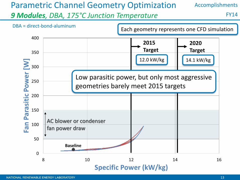
13
Parametric Channel Geometry Optimization 9 Modules, DBA, 175°C Junction Temperature
Baseline
2015 Target
2020 Target
Low parasitic power, but only most aggressive geometries barely meet 2015 targets
Accomplishments
12.0 kW/kg 14.1 kW/kg
DBA = direct-bond-aluminum
FY14
AC blower or condenser fan power draw
Each geometry represents one CFD simulation

14
Parametric Channel Geometry Optimization 6 Modules, DBA, 175°C Junction Temperature
2015 Target
2020 Target
Accomplishments
12.0 kW/kg 14.1 kW/kg
Selection of geometries meets targets with acceptable parasitic power
FY14
Go/ No-Go
2
Each geometry represents one CFD simulation
AC blower or condenser fan power draw

15
Parametric Channel Geometry Optimization 6 Modules, DBA, 175°C Junction Temperature
2015 Target
2020 Target
Accomplishments
12.0 kW/L 13.4 kW/L
Selection of geometries meets targets with acceptable parasitic power
FY14
Go/ No-Go
2
AC blower or condenser fan power draw
Each geometry represents one CFD simulation

16
Heat Exchanger Experiments
Baseline
Optimized
Accomplishments
Prototypes provided by Sapa
FY14
devices
heaters

17
Heat dissipation: 2.7 kW target
Accomplishments
~55 CFM 4 W Fluid Power
Specific Power: 9.4 kW/kg Power Density: 10.1 kW/L
Heat Dissipation for Baseline Case (9 modules)
Fan sized to satisfy flow rate and pressure drop
FY14
Tout ~ 120°C 100°C 70°C

18
Heat Dissipation for Optimized Case (6 modules) Accomplishments
Specific Power: 14.6 kW/kg Power Density: 14.5 kW/L
~200 CFM 110 W Fluid Power
FY14
Go/ No-Go
2
Heat dissipation: 2.7 kW target
Tout ~ 80°C 60°C
Specific power and power density projected to meet 2020 targets, with tradeoff of higher parasitic power

19
Feedback: The reviewer indicated that this is a good team, but felt that a vehicle manufacturer should be added to the team to get industry input. This reviewer suggested that this would help the project to become easier to manufacture and get industry acceptance.
Response: We have a strong collaboration with ORNL. NREL is addressing thermal issues, and ORNL is focused on the electrical design. On the thermal work, NREL is collaborating with Sapa Extrusions North America to aid in manufacturing concerns regarding extruded aluminum, a potential method for simple and inexpensive cooling channels. ORNL is working with device manufacturers and other partners on the electrical design. We have met with OEMs and first-tier suppliers through on site visit presentations to get feedback on the direction of the research and to address the advantages, challenges, and potential applications for vehicle platform adoption. We are addressing the barriers and constraints that they have brought up in these meetings.
Feedback: The reviewer suggested that future work should produce a proof-of-concept of a working prototype and address practical application issues.
Response: This fiscal year, the focus has been shifted from modeling and analysis to direct experimentation and proof-of-concept. Baseline and optimized sub-modules have been tested with data extrapolated to module and inverter level. An optimized module has also been manufactured and will be tested this fiscal year. One module heat sink will be tested for thermal performance at NREL, while another was sent to ORNL so they could mount the electrical topology and test the electrical design.
Feedback: The reviewer observed that this project is very relevant to future wide-band applications because cooling requires significant energy that reduces the EV drive efficiency.
Response: We agree that air cooling is better used on high-temperature application, where the large temperature difference helps overcome the shortcomings of air properties. Wide-band-gap devices provide an emerging opportunity for air cooling as they can be run at higher temperatures. They are more efficient, but with smaller areas, the heat flux is still a challenge. We believe air cooling will be a potential effective alternative to traditional cooling strategies.
Responses to AMR FY13 Reviewers’ Comments

20
Collaboration and Coordination Collaborations • Industry: Sapa Extrusions North America
o Provided aluminum channel heat exchanger prototypes o Offered guidance on manufacturability for various designs and
direction on reducing material and manufacturing costs • Federal Laboratory: Oak Ridge National Laboratory (Madhu Chinthavali)
o Building and testing electrical topology o Provided device information, estimated heat loads, balance-of-
inverter component sizing, and design constraints • University/Industry: WBG Institute (outside Vehicle Technology Office)
o Developing relationships with industry and university partners for potential application of technology
Coordination • Industry: Domestic OEMs and inverter suppliers
o Contributed feedback on research and potential applications through direct one-on-one meetings
OEM = original equipment manufacturer

21
Remaining Challenges and Barriers
• Demonstrating prototype that meets technical targets
Cooling Technology
• Showing how balance-of-inverter components complete efficient inverter packaging
• Under-hood location considerations for vehicle platforms
Packaging
• Parasitic power requirements • Comparison of weight, volume, and cost of
necessary components (i.e. ducting, fans) compared to liquid-cooled loop
Balance of System

22
Electrical and Thermal Module (10 kW) Future Work
Build 10-kW module
Demonstrate 10-kW module (thermal performance)
Build 10-kW module
Demonstrate 10-kW module (electrical performance)
M3
Photo courtesy of ORNL (Madhu Chintavali)

23
System Test Platform
Build and test sample system to measure and characterize parasitic load
Future Work
M3
Jim Snyder, NREL Image Gallery 15165

24
Summary DOE Mission Support • Overcome barriers to accelerate adoption of low-cost air-cooled heat
exchangers for power electronics, especially for high-temperature (i.e. WBG) devices; air remains the ultimate sink
Approach • Create system-level understanding and designs addressing advanced cooling
technology, packaging, and balance of system • Develop solutions from fundamental heat transfer, then system-level design, to
application − culminating in demonstration of concept Collaborations • ORNL developed electrical topology and is testing with NREL air-cooled heat
exchanger and provided balance-of-inverter component sizing and characterization and device loss (heat dissipation) direction
• Sapa Extrusions North America provided aluminum heat exchanger prototypes and guidance on manufacturing constraints to control cost
• Met with OEMs and 1st tier suppliers to obtain feedback on air-cooling applications and overcoming barriers and constraints for adoption

25
Summary Technical Accomplishments • Optimized thermal design showing candidate designs that
meet DOE power density and specific power technical targets with acceptable parasitic loads
• Demonstrated baseline and optimized module design thermal performance and, using balance-of-system assumptions, projected to meet 2015 DOE technical targets
• Built module-level (10-kW) heat exchanger that will be tested in FY14
Maximum Junction Temperature – 175°C
2015 Target
2020 Target
Baseline (9 modules)
Baseline (6 modules)
Optimized (9 modules)
Optimized (6 modules)
Power Density [kW/L] 12.0 13.4 10.1 12.8 11.8 14.5 Specific Power [kW/kg] 12.0 14.1 9.4 12.7 11.1 14.6 Fluid Power [W] N/A N/A 4 34 70 110

26
For more information contact: Principal Investigator Scot K. Waye [email protected] Phone: (303) 275-4454 APEEM Task Leader Sreekant Narumanchi [email protected] Phone: (303)-275-4062
Acknowledgments:
• Susan Rogers and Steven Boyd U.S. Department of Energy
• Andrew Wereszczak Oak Ridge National Laboratory
Team Members:
Matt Musselman Charlie King Kevin Bennion Madhu Chinthavali (ORNL)
Acknowledgments and Contact
Dennis Schroeder, NREL Image Gallery 19050

Technical Back-Up Slides
(Note: please include this “separator” slide if you are including back-up technical slides (maximum of five). These back-up technical slides will be available for your presentation and will be included in the DVD and Web PDF files released to the public.)

28
Optimized Geometries Improve Specific Power On track to meet DOE 2015 technical target
9 modules, DBC
Baseline
Optimized
Changes to channel height and length
FY13 – Go/No-Go 1

29
Component Contributions to Inverter Weight
Other components need optimization

30
• Meets Fan Test Standard o ANSI/AMCA 210-07 o ANSI/ASHRAE 51-07
• Range: 5–500 CFM • U95 Flow: ±1.5 CFM • U95 Pressure: ±1.6 Pa
System Level Test Bench
Fan pressure curves Fan efficiency curves
Fan or duct test subject
Blower

31
Air Outlet Temperature for Baseline Case Accomplishments
~100°C
~55 CFM
FY14

32
Heat Dissipation for Optimized Case (9 modules) Accomplishments
Specific Power: 11.1 kW/kg Power Density: 11.8 kW/L
Heat dissipation: 2.7 kW target
FY14
~70 CFM 70 W Fluid Power
Tout ~ 105°C 90°C 70°C
Similar thermal performance to baseline, but higher specific power and power density, and parasitic power