high temperature durability of a bond-coatless plasma
TRANSCRIPT

HAL Id: hal-01942731https://hal.archives-ouvertes.fr/hal-01942731
Submitted on 3 Dec 2018
HAL is a multi-disciplinary open accessarchive for the deposit and dissemination of sci-entific research documents, whether they are pub-lished or not. The documents may come fromteaching and research institutions in France orabroad, or from public or private research centers.
L’archive ouverte pluridisciplinaire HAL, estdestinée au dépôt et à la diffusion de documentsscientifiques de niveau recherche, publiés ou non,émanant des établissements d’enseignement et derecherche français ou étrangers, des laboratoirespublics ou privés.
High temperature durability of a bond-coatlessplasma-sprayed thermal barrier coating system with
laser textured Ni-based single crystal substrateRobin Kromer, Jonathan Cormier, Sophie Costil, Damien Courapied, Laurent
Berthe, Patrice Peyre
To cite this version:Robin Kromer, Jonathan Cormier, Sophie Costil, Damien Courapied, Laurent Berthe, et al.. Hightemperature durability of a bond-coatless plasma-sprayed thermal barrier coating system with lasertextured Ni-based single crystal substrate. Surface and Coatings Technology, Elsevier, 2018, 337,pp.168-176. �10.1016/j.surfcoat.2018.01.006�. �hal-01942731�

High temperature durability of a bond-coatless plasma-sprayed thermalbarrier coating system with laser textured Ni-based single crystal substrate
R. Kromera,⁎, J. Cormierb, S. Costila, D. Courapiedc, L. Berthec, P. Peyrec
a ICB-LERMPS UMR 6303, Univ. Bourgogne Franche-Comté, UTBM, F-90010 Belfort, Franceb Institut Pprime - Département de Physique et Mécanique des Matériaux UPR CNRS 3346, ISAE-ENSMA, Téléport 2, 1, avenue Clément ADER BP 40109 86961CHASSENEUIL – FUTUROSCOPE, Francec Processes and Engineering in Mechanics and Materials Laboratory (PIMM), CNRS-ENSAM ParisTech, 151 Bd de l'hôpital, 75013 Paris, France
A R T I C L E I N F O
Keywords:Laser texturingThermal barrier coating systemOxidationMechanical adhesionCreep
A B S T R A C T
Thermal barrier coating systems are usually build-up with bond coats to ensure a good adhesion of the ceramictop coat and to protect the substrate against oxidation and corrosion. Such system is often subjected to complexthermo-mechanical loading. Because of the very different damage processes encountered during service op-erations, a simplified system was investigated by removing the bond-coat. Recently adhesion bond strength wasenhanced using laser surface texturing of the substrate in thermal spraying processes. Atmospheric plasma sprayyttria-stabilized-zirconia thermal barrier coating system was deposited on the Ni-based AM1 single crystallinesuperalloy without bond coat. Adhesion bond strength was already increased compared to conventional pro-cessing method. Top coat durability was evaluated at high temperature and damage mechanisms were studied.Isothermal and cyclic oxidation tests showed durability of 1000 h and 400 cycles at 1100 °C. The oxidationmechanisms at the substrate/top coat interface changed due to fast solidification during the laser texturingprocess. Then, TBC system was studied under high temperature mechanical solicitation in tension creep. Thetextured interfaces were not damaged after 1% creep strain while top-coat/substrate interfacial cracking wasobserved for grit-blasted specimens. Moreover, no preferential crack development in the substrate was observed.Patterns provided an enhanced adhesion by changing the stress distribution near the interface.
1. Introduction
Thermal barrier coatings (TBC) are widely used on nickel-basedsuperalloys substrates submitted to prolonged exposures to combustiongases at high operating temperatures in order to increase gas turbineefficiency and to limit hot corrosion and oxidation issues [1]. A typicalTBC system is consisted of three layers: a metallic substrate (generally,a Ni-based superalloy), an alumina-forming metallic bond coat and aceramic top coat [2]. The bond coat has two main functions: protectionof the base material against oxidation and corrosion attack during hightemperature exposure and providing good adhesion of the ceramic topcoat [3]. The latter protects the base material from heat of the flowingcombustion gases [4]. Nevertheless, premature failures due to severalmechanisms still limit the TBC systems durability [5]. Damage me-chanisms in TBC systems under service conditions are complex and thecrack initiation and subsequent propagation, often related to the bondcoat strength and microstructure evolutions [6–8]. Macroscopic spal-lation is triggered by maximum in-plane compressive stress and thedecrease in ceramic/metal interface bond strength due to aging effects
[9]. Interfacial damage is a combination of microstructure evolutionand oxide growth. Both are thermally activated and the thermal stressesmay modify the interface roughness depending on top coat structureand material. The main damaged mechanisms associated to oxidationand roughness increase are called rumpling, and consists in local in-terfacial delamination [10]. The elastic and plastic stored energy in theTGO (Thermal Growth Oxide) and imperfections in its vicinity play asignificant role in the durability of the full TBC system under cyclicoxidation. In addition, any energy release rate of topcoat, for instanceinterface defects, play also a major role. The failure occurs through asequence of crack nucleation, propagation and coalescence eventsduring thermo-mechanical loading applied during service operations ingas turbines [11]. Under high applied stress conditions, a failure me-chanism at substrate/bond coat interface may also be observed due tolarge creep strains and fast creep deformation of the bond coat at hightemperatures above the ductile-brittle transition temperature (DBTT)[12]. Since NiAl(Pt) type bond coats have generally poor creep re-sistance, a TBC system without bond coat was investigated in the pre-sent study. With such a “bond-coatless” TBC system, a mechanical
⁎ Corresponding author.E-mail address: [email protected] (R. Kromer).
T
anchoring was used to ensure a good adhesion of the top-coat to thesubstrate and an alumina-forming superalloy was chosen. For this, asubstrate surface laser patterning was used [11]. As presented pre-viously, the patterns increased the in-contact area and provided mixed-mode failures to obtain cohesive failures locally [14]. Thus, the adhe-sion bond strength of the thermal barrier coating was tripled with lasersurface patterning prior-treatment compared to a standard preparationtechnique (i.e. grit blasting). In the present investigation, the durabilityand failures mechanisms of this new thermal barrier coating systemwithout bond coat were investigated during isothermal and cyclicoxidation experiments as well as during isothermal creep tests. Yttria-zirconia top-coat was deposited on a single-crystal superalloy substrateand this TBC system was investigated during high temperature oxida-tion and creep conditions corresponding to possible high or inter-mediate pressure turbine blade and vanes applications as well as highpressure turbine shrouds. A specific attention will be paid to the role ofsubstrate laser texturing in the damage development.
2. Experimental procedure
2.1. Materials
As referred to useful TBC systems, the studied system is composed ofa plasma-sprayed YSZ top coat deposited on an AM1 single crystal su-peralloy substrate. The AM1 is a first generation nickel-based super-alloy, whose composition is given in Table 1. Before machining thespecimens, single crystalline bars were solution treated at 1300 °C for3 h followed by air cooling and aged at 1100 °C for 5 h followed by aircooling and at 870 °C for 16 h followed by air cooling [15]. Buttonswere machined from single-crystalline bars with a diameter of 14 mmand a thickness of 1.5 mm. The coated surfaces of these buttons wereclosed to a (001) crystallographic plane. Creep specimens were alsomachined from 20 mm AM1 bars. These specimens were machined withthe stress axis close to a [001] crystallographic orientation (devia-tion < 5°). Creep specimens had a gage length of 14 mm and a dia-meter of 4 mm.
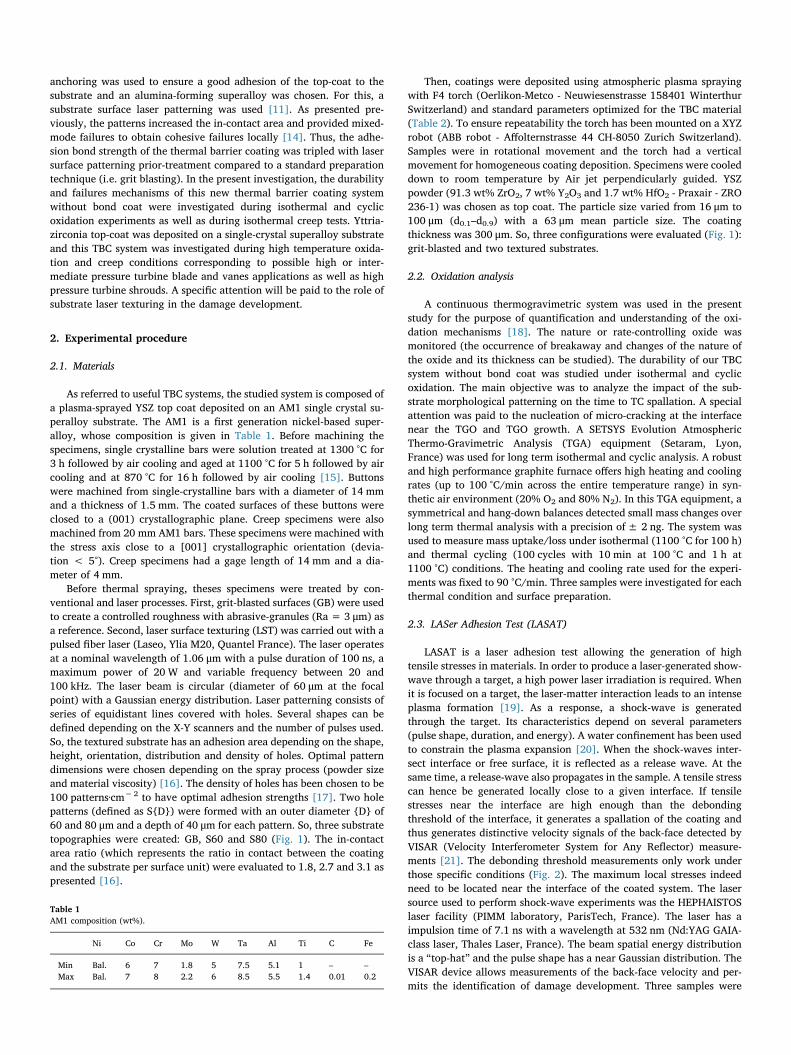
Before thermal spraying, theses specimens were treated by con-ventional and laser processes. First, grit-blasted surfaces (GB) were usedto create a controlled roughness with abrasive-granules (Ra = 3 μm) asa reference. Second, laser surface texturing (LST) was carried out with apulsed fiber laser (Laseo, Ylia M20, Quantel France). The laser operatesat a nominal wavelength of 1.06 μm with a pulse duration of 100 ns, amaximum power of 20 W and variable frequency between 20 and100 kHz. The laser beam is circular (diameter of 60 μm at the focalpoint) with a Gaussian energy distribution. Laser patterning consists ofseries of equidistant lines covered with holes. Several shapes can bedefined depending on the X-Y scanners and the number of pulses used.So, the textured substrate has an adhesion area depending on the shape,height, orientation, distribution and density of holes. Optimal patterndimensions were chosen depending on the spray process (powder sizeand material viscosity) [16]. The density of holes has been chosen to be100 patterns·cm−2 to have optimal adhesion strengths [17]. Two holepatterns (defined as S{D}) were formed with an outer diameter {D} of60 and 80 μm and a depth of 40 μm for each pattern. So, three substratetopographies were created: GB, S60 and S80 (Fig. 1). The in-contactarea ratio (which represents the ratio in contact between the coatingand the substrate per surface unit) were evaluated to 1.8, 2.7 and 3.1 aspresented [16].
Then, coatings were deposited using atmospheric plasma sprayingwith F4 torch (Oerlikon-Metco - Neuwiesenstrasse 158401 WinterthurSwitzerland) and standard parameters optimized for the TBC material(Table 2). To ensure repeatability the torch has been mounted on a XYZrobot (ABB robot - Affolternstrasse 44 CH-8050 Zurich Switzerland).Samples were in rotational movement and the torch had a verticalmovement for homogeneous coating deposition. Specimens were cooleddown to room temperature by Air jet perpendicularly guided. YSZpowder (91.3 wt% ZrO2, 7 wt% Y2O3 and 1.7 wt% HfO2 - Praxair - ZRO236-1) was chosen as top coat. The particle size varied from 16 μm to100 μm (d0.1–d0.9) with a 63 μm mean particle size. The coatingthickness was 300 μm. So, three configurations were evaluated (Fig. 1):grit-blasted and two textured substrates.
2.2. Oxidation analysis
A continuous thermogravimetric system was used in the presentstudy for the purpose of quantification and understanding of the oxi-dation mechanisms [18]. The nature or rate-controlling oxide wasmonitored (the occurrence of breakaway and changes of the nature ofthe oxide and its thickness can be studied). The durability of our TBCsystem without bond coat was studied under isothermal and cyclicoxidation. The main objective was to analyze the impact of the sub-strate morphological patterning on the time to TC spallation. A specialattention was paid to the nucleation of micro-cracking at the interfacenear the TGO and TGO growth. A SETSYS Evolution AtmosphericThermo-Gravimetric Analysis (TGA) equipment (Setaram, Lyon,France) was used for long term isothermal and cyclic analysis. A robustand high performance graphite furnace offers high heating and coolingrates (up to 100 °C/min across the entire temperature range) in syn-thetic air environment (20% O2 and 80% N2). In this TGA equipment, asymmetrical and hang-down balances detected small mass changes overlong term thermal analysis with a precision of± 2 ng. The system wasused to measure mass uptake/loss under isothermal (1100 °C for 100 h)and thermal cycling (100 cycles with 10 min at 100 °C and 1 h at1100 °C) conditions. The heating and cooling rate used for the experi-ments was fixed to 90 °C/min. Three samples were investigated for eachthermal condition and surface preparation.
2.3. LASer Adhesion Test (LASAT)
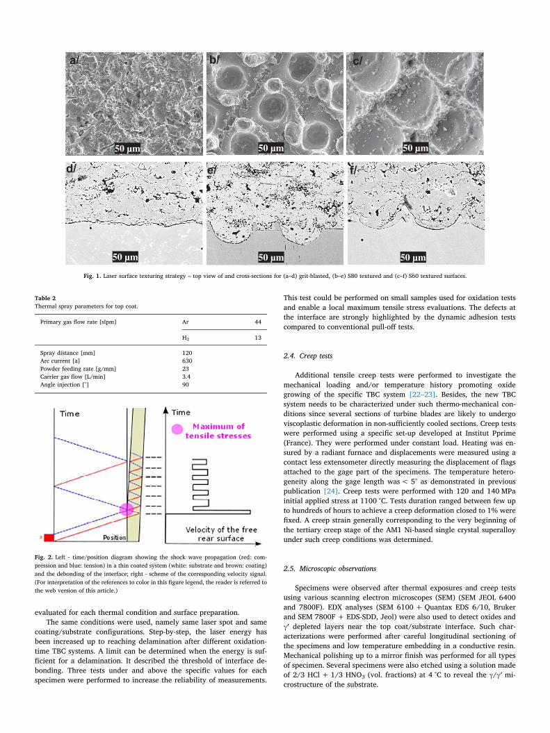
LASAT is a laser adhesion test allowing the generation of hightensile stresses in materials. In order to produce a laser-generated show-wave through a target, a high power laser irradiation is required. Whenit is focused on a target, the laser-matter interaction leads to an intenseplasma formation [19]. As a response, a shock-wave is generatedthrough the target. Its characteristics depend on several parameters(pulse shape, duration, and energy). A water confinement has been usedto constrain the plasma expansion [20]. When the shock-waves inter-sect interface or free surface, it is reflected as a release wave. At thesame time, a release-wave also propagates in the sample. A tensile stresscan hence be generated locally close to a given interface. If tensilestresses near the interface are high enough than the debondingthreshold of the interface, it generates a spallation of the coating andthus generates distinctive velocity signals of the back-face detected byVISAR (Velocity Interferometer System for Any Reflector) measure-ments [21]. The debonding threshold measurements only work underthose specific conditions (Fig. 2). The maximum local stresses indeedneed to be located near the interface of the coated system. The lasersource used to perform shock-wave experiments was the HEPHAISTOSlaser facility (PIMM laboratory, ParisTech, France). The laser has aimpulsion time of 7.1 ns with a wavelength at 532 nm (Nd:YAG GAIA-class laser, Thales Laser, France). The beam spatial energy distributionis a “top-hat” and the pulse shape has a near Gaussian distribution. TheVISAR device allows measurements of the back-face velocity and per-mits the identification of damage development. Three samples were
Table 1AM1 composition (wt%).
Ni Co Cr Mo W Ta Al Ti C Fe
Min Bal. 6 7 1.8 5 7.5 5.1 1 – –Max Bal. 7 8 2.2 6 8.5 5.5 1.4 0.01 0.2
evaluated for each thermal condition and surface preparation.The same conditions were used, namely same laser spot and same
coating/substrate configurations. Step-by-step, the laser energy hasbeen increased up to reaching delamination after different oxidation-time TBC systems. A limit can be determined when the energy is suf-ficient for a delamination. It described the threshold of interface de-bonding. Three tests under and above the specific values for eachspecimen were performed to increase the reliability of measurements.
This test could be performed on small samples used for oxidation testsand enable a local maximum tensile stress evaluations. The defects atthe interface are strongly highlighted by the dynamic adhesion testscompared to conventional pull-off tests.
2.4. Creep tests
Additional tensile creep tests were performed to investigate themechanical loading and/or temperature history promoting oxidegrowing of the specific TBC system [22–23]. Besides, the new TBCsystem needs to be characterized under such thermo-mechanical con-ditions since several sections of turbine blades are likely to undergoviscoplastic deformation in non-sufficiently cooled sections. Creep testswere performed using a specific set-up developed at Institut Pprime(France). They were performed under constant load. Heating was en-sured by a radiant furnace and displacements were measured using acontact less extensometer directly measuring the displacement of flagsattached to the gage part of the specimens. The temperature hetero-geneity along the gage length was< 5° as demonstrated in previouspublication [24]. Creep tests were performed with 120 and 140 MPainitial applied stress at 1100 °C. Tests duration ranged between few upto hundreds of hours to achieve a creep deformation closed to 1% werefixed. A creep strain generally corresponding to the very beginning ofthe tertiary creep stage of the AM1 Ni-based single crystal superalloyunder such creep conditions was determined.
2.5. Microscopic observations
Specimens were observed after thermal exposures and creep testsusing various scanning electron microscopes (SEM) (SEM JEOL 6400and 7800F). EDX analyses (SEM 6100 + Quantax EDS 6/10, Brukerand SEM 7800F + EDS-SDD, Jeol) were also used to detect oxides andγ′ depleted layers near the top coat/substrate interface. Such char-acterizations were performed after careful longitudinal sectioning ofthe specimens and low temperature embedding in a conductive resin.Mechanical polishing up to a mirror finish was performed for all typesof specimen. Several specimens were also etched using a solution madeof 2/3 HCl + 1/3 HNO3 (vol. fractions) at 4 °C to reveal the γ/γ′ mi-crostructure of the substrate.
a/ b/ c/
d/ e/ f/
50 µm
50 µm 50 µm 50 µm
50 µm 50 µm
Fig. 1. Laser surface texturing strategy – top view of and cross-sections for (a–d) grit-blasted, (b–e) S80 textured and (c–f) S60 textured surfaces.
Table 2Thermal spray parameters for top coat.
Primary gas flow rate [slpm] Ar 44
H2 13
Spray distance [mm] 120Arc current [a] 630Powder feeding rate [g/mm] 23Carrier gas flow [L/min] 3.4Angle injection [°] 90
Fig. 2. Left - time/position diagram showing the shock wave propagation (red: com-pression and blue: tension) in a thin coated system (white: substrate and brown: coating)and the debonding of the interface; right - scheme of the corresponding velocity signal.(For interpretation of the references to color in this figure legend, the reader is referred tothe web version of this article.)

3. Results
3.1. Isothermal and cyclic oxidation
Isothermal oxidation at 1100 °C for 5 h up to 100 h and thermalcycling oxidation from 5 up to 100 cycles at 1100 °C for 1 h were per-formed for grit blasted (GB) and laser treated (S80 and S60) specimens.The relative mass change for isothermal and thermal cycling oxidationup to 100 h was plotted in Fig. 3 (continuous and dotted-lines respec-tively). Each single specimen's measurement is calculated per surfaceunit using image analysis to calculate the area exposed to oxidation. Inthis way, the additional area due to the presence of holes for texturedspecimens was taken into account knowing their morphology and thedensity.
First, a mass gain is observed for each specimen under both iso-thermal and thermal cycling conditions. Different evolutions of therelative mass change are observed, both during the first hours of oxi-dation and after 60 h. Moreover, the application of a thermal cyclingfavors the oxidation of all the specimens by micro-cracks formation,especially for short oxidation durations (below 20 h). The impact of thethermal cycling on the relative mass uptake is in good agreement withPoquillon et al. for two NiAl single crystals [25]. Then, it is also noticedthat the oxidation kinetics are dependent on the surface preparation.Grit-blasted specimens present a faster oxide growth than laser treatedones for the first hours of oxidation. After about 30 h of oxidation, lasertreated specimen always exhibit a higher mass uptake compared to gritblasted ones. The relative mass changes were low after 100 h or100 cycles. It is supposed that a protective layer was grown.
Under high temperature (T > 1000 °C), it was found that the oxidefilm on AM1 superalloy consists of two layers (Fig. 4), i.e., an innerlayer from the side of the metal substrate, which is composed of or-iented grains of α-Al2O3, and an outer layer, which comprises orientedgrains of NiAl2O4 spinel [26]. It is also observed that the oxidation ofthe substrate resulted in a γ′-depleted layer (i.e. without any γ′ parti-cles) as usually observed in the literature [27]. The two layers of the
oxide scale are separated by discrete inclusions of tantalum and tita-nium oxides (bright spots in the backscattered electron image). So,multi-layer oxides were observed and the transition in oxidation be-havior can be deduced with the alumina phase changes. However, thealpha alumina can be defined has a protective layer after 50 h. Suchmulti-layered oxides were observed for the different specimens(Fig. 4a).
For grit-blasted samples, the plastic deformation induced by theabrasion process changed the oxide growth. Al2O3 oxide was the mainTGO. The spinels and inclusions were not clearly defined. Moreover,cracked oxides were noticed for GB after 100 h (see Fig. 4b). It might bethe consequences of mixed spallation: cracks propagated through TBC/TGO or TGO/substrate interface. The misfit leads to compressivestresses and the curvature gives different stresses components. APS TBChas a lamellar structure which is not adapted to support perpendicularstresses (i.e. thermal misfit strains between substrate and TBC). Fortextured substrates, laser treatments promoted a multi-layered oxidescale similar to the polished substrate (Fig. 4c). Besides, the inclusionswere well defined between the inner and outer layers.
3.2. Time to spallation of the top-coat under high temperature oxidation
Fig. 5 shows the evolution of the adhesion strength determined bythe LASAT test for grit-blasted and laser textured specimens, both afterisothermal and cyclic oxidation tests. Four samples were evaluated foreach condition.
First the laser adhesion test allowed evaluating the interface topo-graphy effect on adhesion [28]. It was confirmed by the authors that thelaser surface texturing enhanced the adhesion bond strength by mixed-mode failures under quasi-static and dynamic stresses [17]. Then, afterhigh temperature exposure, the adhesion threshold changed. For iso-thermal oxidation, an optimal value after 100 h was noticed, meaningthat a high interfacial toughness is obtained after such an exposuretime, as already observed previously by Vaunois [30]. The physico-chemical compatibility was optimal between YSZ/TGO after 100 h,corresponding to a TGO scale mainly composed of dense and con-tinuous α-Al2O3. It is suspected to be linked to a higher substrate/oxideinterfacial toughness associated to the formation of a continuous anddense inner α-Al2O3 oxide layer in the TGO. The improvement washigher for S80 due to larger in-contact area. Moreover, the adhesionstrength decreased almost linearly after 100 h for isothermal exposurewhatever the specimen type. As observed Fig. 6, GB specimens spalled(i.e. a zero adhesion threshold) after 350 h while S60 and S80 wouldreach spontaneous spallation threshold for durations in the1500–2000 hours range.
Finally, it was shown that the introduction of a thermal cyclingduring oxidation tests leaded to a faster decrease of the TC adhesion. GBspecimens were observed to spall before 200 h (spallation after170 cycles). Larger roughness (Ra = 5.3 and 8.2 μm) was investigatedto check this behavior. The spallation time was equal to 220 ± 30 and280 ± 20 μm respectively. So, the morphological patterning had a
Fig. 3. Relative mass change as a function of time for isothermal and thermal cycling tests– grit-blasted (GB) and laser textured (S80 and S60) samples – errors of 0.0002 mg·cm−2.
v
/c/b/a
1µm 1µm 1µm
Fig. 4. Cross-sections for polished (a), grit-blasted (b) and laser treated (c) samples after 100 h of isothermal oxidation at 1100 °C – from top to bottom: TC (light), spinel (grey), aluminaoxide (dark) and substrate (light).

strong impact on adhesion.Even if laser treated specimens did not exhibit spallation of the TC
after 200 h of thermal cycling, it was observed a spectacular decrease ofthe adhesion, hence highlighting the detrimental effect of thermal cy-cling. For these laser treated specimens, a TC spallation life between400 and 500 cycles was expected (linear extrapolation from the trendpresented in Fig. 5). Thermal cycling tests up to such durations woulddeserve to be performed to confirm this estimation.
Vaunois [30] or Liu et al. [31] presented metallographic char-acterizations of failure modes in plasma sprayed TBC systems evaluatedin isothermal oxidation at 1100 °C. It was found that the durability ofcommercial quality TBC system is related to progress of degradationmodes of bond coat and top layer. During isothermal oxidation test, thebond coat was oxidized to form of a dense alumina and a porous mixedoxide layer between the YSZ top coat and a bond coat made of NiCo-CrAlY alloy. At the moment of oxidation acceleration, the process ofcrack initiation and propagation was observed mainly in the mixedoxide layer near the YSZ. The observed crack propagation induced thedelamination and spallation of top coat after 500 h oxidation. In thisstudy, the lifespan was in the same range of our GB samples withoutbond coat, even if the interface roughness was lower in our case com-pared to these previous studies. So, laser surface texturing results can beconsidered to increase the lifespan under the same conditions.
Microstructure observations along cross sections were performed(see Figs. 6 and 7). Microstructures close to TC/substrate interface aspresented were observed in the as-deposited state (i.e. without any hightemperature oxidation), after 100 h of isothermal oxidation at 1100 °Cand after 100 cycles in cyclic oxidation. Grit-blasting created a specificroughness by plastic deformation of the substrate and erosion me-chanisms. The superalloy microstructure was hence highly deformed atthe extreme surface (Fig. 6a). The compressive stresses due to grit-blasting affected the microstructure during oxidation (both isothermal
and cyclic oxidation) and 4 affected zones were distinguished: 1/ a γ′depleted layer, 2/ a layer showing cellular recrystallization, 3/ atransition zone and 4/ the substrate standard microstructure, whose γ′particles have coarsened during thermal exposure (Fig. 6b). The areasof cellular recrystallization were direct linked to the residual stressesintroduced during the grit-blasting and are suspected to affect the TGOgrowth mechanisms [32]. It was noticed interfacial porosity betweenthe TGO and the top coat promoting crack initiation areas (Fig. 6b).Cracks were indeed observed following this interface during isothermaltests. Besides, few parts of the coating stayed attach to the substrateafter thermal cycling tests (Fig. 6c). The difference of thermal expan-sion coefficients are known to create stresses during the solidification,leading to interfacial and intersplats cracks, as observed in Fig. 6c.
LST created patterns by vaporization and recoil pressure mechan-isms [33]. A melted layer with ~1 μm thickness can be observed in thebottom of the pattern in addition to resolidified matter on the edges(Fig. 7a). No evidence of local recrystallization was noticed in the vi-cinity of the keyholes created by the LST process. A continuous TGOwas observed after thermal exposure but no crack initiation was clearlyidentified after isothermal oxidation tests. The edges were the areaswhere the first cracks started (arrow Fig. 7b). The maximum solicitationarea was supposed on the edges during TGO growth. Therefore, damagedevelopment above the hole was observed during thermal cyclingtreatments (dashed-arrow Fig. 7c). It was observed on the differentspecimens. A compressive stress state in the hole enabled deviations ofcracks in the coating [34] Thus, the time for TC spallation was limitedby the coating mechanical properties due to this failure mode. Indeed,S80-textured specimens have a larger adhesion strength (see Fig. 6) dueto larger cohesive area in comparison to S60 (larger section diameter),which supports this assumption.
3.3. Creep tests
A viscoplastic deformation at high temperature was introduced byperforming tension creep tests to investigate the development of da-mage with the superposition of a load. It is recalled that creep testswere purposely interrupted after reaching nearly a 1% creep strain. Itcorresponds to the onset of tertiary creep. Also, we did not want toinvestigate failed specimens in which the local increase in stresstriaxiality in the necking region of the specimen would affect at thecoating cracking. The failure mechanisms of the TBC system involvedduring both long (i.e. applied stress = 120 MPa) and short (i.e. appliedstress = 140 MPa) creep tests were investigated in the vicinity of theTGO (i.e. top coat/TGO and TGO/substrate interfaces). The objectivewas to deduce the major factor of TC spallation such as oxide growth orcreep deformation. Fig. 8 shows low (120 MPa) and high (140 MPa)creep curves for grit-blasted and laser textured samples. Cross-sectionsafter creep tests are presented in Fig. 9.
Fig. 9a and b show that an entire top coat/TGO delamination wasobtained at the end of creep tests. On the contrary, patterns enabled thecoating/substrate contact integrity after the creep tests with no clear
0
1
2
3
4
5
6
0 200 400 600 800 1000
Adh
esio
n th
resh
old
(GW
/cm
²)
Time (h)
GB-Iso
S80-Iso
S60-Iso
GB-Cycl
S80-Cycl
S60-Cycl
Fig. 5. Adhesion threshold for grit-blasted (GB) and laser textured (S60 and S80) speci-mens for isothermal (Iso) and cycled thermal (Cycl) tests – three samples were evaluatedfor each thermal condition and surface preparation.
20µm 20µm 20µma/ b/ c/Fig. 6. Cross-sections of GB specimens in the as-processed state (a), after 100 h of isothermal oxidation (b) and 100 thermal cycles (c) at 1100 °C. Four zones:1/ γ′ depleted layer, 2/cellular recrystallization, 3/ transition zone and 4/ standard microstructure – circles identified interface porosity and intersplats cracks.

proof of crack initiation in this interface (Fig. 9c and d). Laser surfacetexturing hence allowed a sufficient anchoring compared to grit-blasting.
The creep behavior is observed to be very similar between GB (1%creep strain in 525 h) and S80 (1% creep strain in 650 h) specimens fora 120 MPa applied stress. However, with a 140 MPa applied stress, it isobserved a pronounced decrease of the time to reach 1% creep strain forthe grit-blasted specimen in comparison to the laser-textured one. Theearlier onset of tertiary creep for grit-blasted specimens might be ex-plained by the grit-blasting consequences on the extreme surface mi-crostructure of the substrate. It was observed in the present study (see
Fig. 10) surface recrystallization after creep tests using grit-blastedspecimens, due to surface compressive residual stresses present at thebeginning of the tests. No recrystallization has been noticed in laser-textured specimen (only few zones on the plateau). Such a re-crystallization mechanism has already been observed previously forsimilar creep conditions and alloys [35]. The volume fraction of re-crystallized zone under tensile loading has almost no bearing capacity[36], and as a result, the actual stress acting on the unrecrystallizedsubstrate is larger, which is the main cause for the lower creep life of GBspecimen, especially for a 140 MPa applied stress. The recrystallizedzone was measured to be equal to 24 ± 4 μm for creep tests performedat 120 MPa and 36 ± 7 μm under 140 MPa creep conditions. Takinginto account this recrystallized layer, the applied stress was estimatedto be 125 MPa instead of 120 MPa and 147 MPa instead of 140 MPa. Itis also worth mentioning that the patterns were taken into account inthe section computation as they decrease the net bearing capacity of thesubstrate.
For the sake of comparison, Riallant et al. [37] have studied thedamage mechanisms of AM1/NiAlPt/EBPVD YSZ system under thesame creep conditions. Time for 1% of deformation was evaluated to500 and 50 h for this TBC “standard” system under 120 and 140 MPa,respectively. They observed YSZ/TGO delamination after 1% of creepdeformation. In addition, they noticed porosity at the bond coat/sub-strate interface. So, for GB specimens, evidences of delamination were
30µm30µm30µma/ b/ c/Fig. 7. Cross-sections of S80 specimens in the as processed state (a), after 100 h of isothermal oxidation (b) and 100 thermal cycles (c) at 1100 °C – circle: resolidified ejected material,arrow: crack with isothermal oxidation, Dashed-arrow: crack with anisothermal oxidation.
Fig. 8. Creep behavior at 1100 °C/120 MPa (a) and 1100 °C/140 MPa (b).
100µm
a/ b/
c/ d/
100µm
100µm100µm
Fig. 9. Cross section observations after creep testing at1100 °C/120 MPa of grit blasted (a) and laser textured(S80) specimens (c) and after creep testing at 1100 °C/140 MPa of grit blasted (b) and laser textured (S60) spe-cimens (d).

observed at the interface of the oxide layer. But, for LST, no debondingwas observed, whatever the creep conditions (see Fig. 10b and d). Be-sides the oxide layers were continuous along the patterns/coating in-terface. The constant applied loading has only created few cracks on thetop coat extreme surface (not shown here). Finally, there were nocracks running through the substrate from the patterns, due to the localstress concentration within the substrate. Hence, this “bond-coatless”system with laser surface texturing enabled a comparable (or evenbetter) durability under high-temperature oxidation and creep condi-tions.
4. Discussion
It has been observed in the present study that laser surface texturingseems to be a reliable process to increase the time to spallation of anAPS YZS top coat deposited on the AM1 Ni-based single crystal super-alloy during isothermal and cyclic oxidation, but also in creep at1100 °C. This new bond-coat-less TBC system could be considered as agood candidate for high temperature turbine blade, vanes or shroudsapplications, especially if the substrate presents intrinsic good oxidationand corrosion resistances.
To explain the possible origins of this improvement in time tospallation compared to a standard grit-blasting process few argumentscan be highlighted. Post-processing TGA data (see Fig. 3) to extract themass gain rate as a function of time enabled a parabolic rate constantevaluation of grit-blasted (GB) and laser textured (S80) specimens. Thevariations of mass gain versus time can be fitted to a parabola accordingto Eq. (1) [38]:
= + +t A BΔm CΔm2 (1)
The kinetics parameters can be evaluated from the coefficients A, B,and C obtained from such a fit. The most important feature is that thesecond degree coefficient C is always the reciprocal of the “true”parabolic rate constant kp. The fitting of the experimental data to acomplete parabola permits a correct evaluation of the kp value in-dependently of the effective oxidation mechanism and/or the occur-rence of a transient oxidation regime. Fig. 11 shows the evolution overtime of the parabolic rate constant kp for grit-blasted and laser texturedsamples under isothermal and thermal cycling oxidation tests.
As presented, a transition zone can be observed before 1.7 h sys-tematically. The curves decreased fast. The different regions were dis-cussed. Raman spectroscopy analysis was used to evaluate the oxidenature (Fig. 12). The transient oxidation mechanisms can then beconfirmed from a θ-Al2O3 to α-Al2O3 phase. As observed by Huang andPeng [39], based on the SEM and Raman analyses, when oxidationstarts θ-Al2O3 preferentially nucleates. Then, the θ-Al2O3 nuclei quicklylink together to form a continuous layer. Later on, the α-Al2O3 layergrows out-ward under the control of aluminum cation diffusion andinward under the control of oxygen anion diffusion. Thereafter, the α-Al2O3 develops a continuous layer at the interface. Finally, the θ-Al2O3
to α-Al2O3 transformation occurs under high temperature. The oxidevolume contraction due to the phase changes can generate micro-
cracks, which are visible on the patched surface. The two specific sig-natures were hence observed using Raman spectroscopy.
The first stage showed larger oxidation kinetics for GB than LSTspecimens. The surface plastic deformation induced faster oxide scalegrowth and it might be induced by the elastic and plastic stored energy.The concentration differences of specific element were not deducedfrom EDX analysis. For the second phase, the stable parabolic rateconstant is not clear different for the different surface treatments.Audigié [40] shows that kp was equal to 9.5.10−8 mg2·cm−4·s−1 forpolished AM1 superalloy at 1100 °C. In this case, kp value is lightlybigger compared to Audigié et al. REF value which can be explained bycracked oxides for GB or by spinels continuous growth for LST speci-mens. Thus, a protective layer can be confirmed with the kp stabiliza-tion. Near interface, stresses were supposed due to micro-cracks for-mation. It might be explained by the volume contraction and growth
a/ b/
20µm 20µm
Fig. 10. Cross-sections of (a) grit-blasted and (b) lasertextured (S80) after isothermal oxidation - recrystalliza-tion highlight.
Fig. 11. Parabolic rate constant evolution for grit-blasted (GB) and laser textured (S80)samples under isothermal and thermal cycling oxidation at 1100 °C - three samples wereevaluated for each thermal condition and surface preparation.
Fig. 12. Raman spectroscopy results compared to standard θ-Al2O3 to α-Al2O3 - drawingof the oxide layer.

rate linked to the thermal tests. According to Fig. 11 where almost si-milar oxidation kinetics for GB and LST specimens after 2 h of oxidationwere noticed, the differences in top coat adhesion between both type ofspecimen as revealed by the LASAT testing procedure may only resultfrom the nature of the oxide scale, especially the one developed withinthe first hours of oxidation. Moreover, the cracked TGO as observed forGB specimens in Fig. 5b may also decrease the time to spallation underboth isothermal and thermal cycling conditions.
This new textured TBC system enables a large durability by in-creasing the mechanical anchoring mechanisms. The patterns seem tochange the distributions of crack propagation [41]. Ranjbar-Far et al.[42] have developed a numerical modeling with the finite element codeABAQUS considering a non-homogenous temperature model to studythe thermo-mechanical behavior of the thermal barrier coatings system.Among many factors affecting the durability and failure mechanisms ofthermal spray coatings during their service life, the residual stressesresulting from the coating process and temperature gradient play animportant role. The interface topography affects the residual stressdistribution near the interface. Low roughness amplitudes causestraight transversal crack paths, whereas a high amplitude roughnessresults in kinked crack paths (Fig. 13). Evans and Taylor [43] indeeddemonstrated that the presence of a large surface roughness leads to aspatial variation in continuity strains which will result in out-of-planetensile stresses at the exposure temperature. The development of fast-growing non-protective oxides due to aluminum depletion (chemicalfailure) is developed at the tips of bond coat protuberances. It increaseswith the roughness modification in the cyclic thermal treatments. Withflatter interfaces, delamination can proceed by growth of wedge crackswhich develop along the TGO/bond coat interface during cooling.
So, oxide micro-cracks might be deduced from a large oxide growthrate after grit-blasting. For a rough interface, stresses in the top coat,TGO and substrate result from thermal expansion mismatch and TGOgrowth. So, damage can be accumulated near TGO-ceramic interfacedue to coating structure and oxide micro-cracking. Critical-size crackproduces spallation due to large in-plane stresses. Therefore, for laserpatterned substrate, compressive stresses were generating in patterndue to the concave shape during coating build-up. Oxides growthcaused an increasing tensile stresses in the pattern while pushing thepeak regions into compression. Cracks could be seen above peaks andaround patterns. They propagated above concave shape due to coatinglamellar structure. So, remelted material on the pattern edges could bebeneficial and play a role of “snap fastener”. Fig. 14 summarizes thedamaging mechanisms of grit-blasted and laser textured surfaces as afunction of time. The failure mechanisms could be deduced as a“buckling” mechanism for GB specimens. In addition, the fast TGOgrowth enabled multi-crack location. On the contrary, the top coat in-trinsic toughness (inter-lamellar defects and anisotropic structure) isthe life limiting factor for LST specimens. The crack propagated abovethe patterns and the oxide growth was smoother in this case. The la-mellar structure helps the buckling mechanisms.
Finally, the TGO thickness evolution has been plotted in Fig. 15 forgrit-blasted and laser treated specimens, for isothermal and thermalcycling oxidation treatments. The TGO thicknesses after creep testshave been superimposed in this plot. Parabolic curves are observed andare logically linked to mass rate changes presented previously.
It is observed that creep specimens developed thicker TGO
compared to both their stress free oxidation specimens. This could bedue to the TGO in the meantime of creep elongation. Besides, for grit-blasted samples, it can be deduced an oxide thickness limit for dela-mination under isothermal oxidation. Then, with stress imposed to thestructure such as creep, stresses near the interface accelerated crackinitiation and propagation. So, for low applied stress creep tests, theoxide thickness overcome the oxide thickness limit identified from pureoxidation tests. The duration of thermal exposure can be deduced as themain damaging mechanisms in this case. On the contrary, under140 MPa, the oxide thickness was smaller. So, the mechanical appliedstress favored the buckling mechanisms.
Finally, for similar creep strains, grit-blasted and laser texturedsamples have shown pronounced differences in terms of resistance tointerfacial crack initiation. The patterns increased adhesion strengthdue to the complex interface morphology. Time to spallation was de-duced to be equal to 1500 h under pure isothermal exposure, withoutany applied stress (Fig. 6). Despite a larger oxide thickness during creep
Fig. 13. Crack propagation behavior in the TBCs and its dependence on the morphologyof the TGO layer and TC/BC interface [28].
Fig. 14. Stresses and crack propagation in the TBC after cooling for flat and concaveshape combined creep and oxidation.
Fig. 15. TGO thickness evolution during isothermal and thermal cycling oxidation at1100 °C for GB, S60 and S80. Data extracted after creep tests at 1100 °C have been addedin this plot - three samples were evaluated for each thermal condition and surface pre-paration.

tests under both 120 and 140 initial applied stresses, the interface wasnot damaged. The mechanical applied stress, under creeping tests,normally should increase the damaging mechanisms. It is hence sus-pected that the surface morphology changed the stress distribution nearthe interface and it seems to be benefic.
Future research will be dedicated to laser textured TBC systems withand without bond coat using APS and EB-PVD deposition processes forwhich failure mechanisms are different. Laser surface treatmentstrategy needs to be developed to enhance adhesion under thermo-mechanical solicitations. Topography could be optimized depending onthe component (e.g. turbine blade) shapes, thermal gradients or mate-rials.
5. Conclusions
The impact of the laser patterning on a bond-coat-less TBC coatingsystem has been investigated at 1100 °C, during isothermal and thermalcycling oxidation, as well as during creep tests. According to this work,the following main conclusions can be established:
• Laser texturing of the substrate surface improve the time to spalla-tion during both isothermal and thermal cycling creep tests at1100 °C compared to a standard grit-blasting process.
• The grit-blasting induces surface recrystallization of the substrate,leading to an earlier onset of the tertiary creep stage.
• The improved time to spallation in creep and thermal cycling oxi-dation after laser patterning of the substrate results from a change inthe top coat stress distribution, in addition to the growth of a denseand continuous inner α-Al2O3 TGO.
Acknowledgements
The authors gratefully acknowledge the ANR (Agence National de laRecherche) for financial assistance in the ARCOLE (12-BS09-0009)project. A part of this study is conducted in the framework of the LABEXINTERACTIFS at Institut Pprime UPR CNRS 3346 under contractnumber ANR-11-LABX-0017.
References
[1] X.Q. Cao, R. Vassen, D. Stoever, Ceramic materials for thermal barrier coatings, J.Eur. Ceram. Soc. 24 (1) (Jan. 2004) 1–10.
[2] D.R. Clarke, S.R. Phillpot, Thermal barrier coating materials, Mater. Today 8 (6)(2005) 22–29.
[3] R. Eriksson, S. Sjostrom, H. Brodin, S. Johansson, TBC bonding coat top coat in-terface roughness, Surf. Coat. Technol. 51 (2013).
[4] T. Hüttel, Investigation of the High Temperature Performance of Thermal BarrierCoating Systems for Steam Turbine Applications, University of Aachen, 2010 (PhDthesis).
[5] J.A. Haynes, E.D. Rigney, M.K. Ferber, W.D. Porter, Oxidation and degradation of aplasma-sprayed thermal barrier coating system, Surf. Coat. Technol. 86 (1996)102–108.
[6] R.D. Jackson, The Effect of Bond Coat Oxidation on the Microstructure andEndurance of Two Thermal Barrier Coating Systems, University of Birmingham,2010 (PhD thesis).
[7] T.M. Pollock, B. Laux, C.L. Brundidge, A. Suzuki, M.Y. He, Oxide-assisted de-gradation of Ni-base single crystals during cyclic loading: the role of coatings, J.Am. Ceram. Soc. 94 (2011) 136–145.
[8] M.A. Lafata, L.H. Rettberg, M.Y. He, T.M. Pollock, Oxidation-assisted crack growthin single-crystal superalloys during fatigue with compressive holds, Metall. Mater.Trans. A 41 (1) (2017) 1–12.
[9] K. Al-Athel, K. Loeffel, H. Liu, L. Anand, Modeling decohesion of a top-coat from athermally-growing oxide in a thermal barrier coating, Surf. Coat. Technol. 222(2013) 68–78.
[10] D. Balint, J. Hutchinson, An analytical model of rumpling in thermal barrier coat-ings, J. Mech. Phys. Solids 53 (4) (2005) 949–973.
[11] S.R. Choi, D. Zhu, R.A. Miller, Fracture behavior under mixed-mode loading ofceramic plasma-sprayed thermal barrier coatings at ambient and elevated tem-peratures, Eng. Fract. Mech. 72 (13) (2005) 2144–2158.
[12] A. Moridi, M. Azadi, G.H. Farrahi, Thermo-mechanical stress analysis of thermal
barrier coating system considering thickness and roughness effects, Surf. Coat.Technol. 242 (2014) 91–99.
[14] R. Kromer, J. Cormier, S. Costil, Laser surface patterning to enhance adhesion ofplasma sprayed coatings surface and coatings technology, Surf. Coat. Technol. 278(2015) 171–182.
[15] P. Caron, C. Ramusat, F. Diologent, Influence of the γ′ fraction on the γ/γ′ topo-logical inversion during high temperature creep of single crystal superalloys,Proceedings of the 11th International Symposium on Superalloys, 2008, pp.159–167.
[16] R. Kromer, J. Cormier, S. Costil, Role of powder granulometry and substrate to-pography in adhesion strength of thermal spray coatings, J. Therm. Spray Technol.25 (5) (2016) 933–945.
[17] R. Kromer, S. Costil, J. Cormier, L. Berthe, P. Peyre, D. Courapied, Laser patterningpretreatment before thermal spraying: a technique to adapt and control the surfacetopography to thermomechanical loading and materials, J. Therm. Spray Technol.25 (3) (Feb. 2016) 401–410.
[18] A. Raffaitin, D. Monceau, E. Andrieu, F. Crabos, Cyclic oxidation of coated anduncoated single-crystal nickel-based superalloy MC2 analyzed by continuous ther-mogravimetry analysis, Acta Mater. 54 (17) (Oct. 2006) 4473–4487.
[19] L. Berthe, M. Arrigoni, M. Boustie, J.P. Cuq-Lelandais, C. Broussillou, G. Fabre,M. Jeandin, V. Guipont, M. Nivard, State-of-the-art Laser Adhesion Test (LASAT), 1Taylor Francis, 2011, pp. 1–15.
[20] L. Berthe, R. Fabbro, P. Peyre, L. Tollier, E. Bartnicki, Shock waves from a water-confined laser-generated plasma, J. Appl. Phys. 82 (6) (1997) 2826–2834.
[21] L.M. Barker, R.E. Hollenback, Laser inteferometer for measuring high velocities ofany reflecting surface, J. Appl. Phys. 43 (1972) 4669–4674.
[22] R. Subramanian, Y. Mori, S. Yamagishi, M. Okazaki, Thermo-mechanical fatiguefailure of thermal barrier coated superalloy specimen, Metall. Mater. Trans. A 46 (9)(Sep. 2015) 3999–4012.
[23] F. Riallant, J. Cormier, A. Longuer, X. Milhet, J. Mendez, High-temperature creepdegradation of the AM1/NiAlPt/EBPVD YSZ system, Metall. Mater. Trans. A 45A(January) (2014) 351–359.
[24] J. Cormier, M. Jouiad, F. Hamon, P. Villechaise, X. Milhet, Very high temperatyrecreep behavior of a single crystal Ni-based superalloy under complex thermal cy-cling conditions, Philos. Mag. Lett. 90 (8) (2010) 611–620.
[25] D. Poquillon, D. Oquab, D. Monceau, Cyclic oxidation kinetics modeling of NiAlsingle crystal, Mater. Sci. Forum 461 (2004) 737–746.
[26] E.N. Fedorova, D. Monceau, D. Oquab, S.A. Khudonogov, High-temperature oxi-dation of nickel-based alloys and estimation of the adhesion strength of resultingoxide layers, Prot. Met. Phys. Chem. Surf. 47 (3) (May 2011) 347–353.
[27] B. Albert, R. Volkl, U. Glatzel, High-temperature oxidation behavior of two nickel-based superalloys produced by metal injection molding for aero engine applica-tions, Metall. Mater. Trans. A 45A (September) (2014) 4561–4572.
[28] D. Courapied, R. Kromer, L. Berthe, P. Peyre, S. Costil, J. Cormier, M. Boustie,X. Milhet, Laser adhesion test for thermal sprayed coatings on textured surface bylaser, Laser Appl. 28 (2) (May 2016).
[30] J.R. Vaunois, Modélisation de la durée de vie des barrières thermiques par ledéveloppement et l'exploitation d'essais d'adhérence, University of Grenoble, 2013(PhD thesis).
[31] Y. Liu, Y. Liu, P. Lours, T. Sentenac, V. Vidal, Z. Wang, K. Ding, Influence of iso-thermal aging conditions on APS TBC's interfacial fracture toughness, Surf. Coat.Technol. 313 (2017) 417–424.
[32] X. Jichun, L. Jiarong, L. Shizhong, Surface recrystallization in nickel base singlecrystal superalloy D6, Chin. J. Aeronaut. 23 (2010) 478–485.
[33] V.V. Semak, J. Hopkins, M.H. McCay, T.D. McCay, A concept for a hydrodynamicmodel of keyhole formation, SPIE 2500 (1994) 64.
[34] M. Baker, T. Fiedler, J. Rosler, Stress evolution in thermal barrier coatings forrocket engine applications, Mech. Adv. Mater. Mod. Process. 1 (1) (Sep. 2015) 1–5.
[35] D.U. Furrer, H.J. Fecht, Gamma′ formation un superalloy U720LI, Scr. Mater. 40(11) (1999) 1215–1220.
[36] J. Meng, T. Jin, X. Sun, Z. Hu, Effect of surface recrystallization on the creep ruptureproperties of a nickel-base single crystal superalloy, Mater. Sci. Eng. A 527 (2010)6119–6122.
[37] F. Riallant, J. Cormier, A. Longuet, X. Milhet, J. Mendez, High-temperature creepdegradation of the AM1/NiAlPt/EBPVD YSZ system, Metall. Mater. Trans. A 45 (1)(Jan. 2014) 351–360.
[38] D. Monceau, B. Pieraggi, Determination of parabolic rate constants from a localanalysis of mass-gain curves, Oxid. Met. 50 (6) (1998) 477–494.
[39] Y. Huang, X. Peng, The promoted formation of an α-Al2O3 scale on a nickel alu-minide with surface Cr2O3 particles, Corros. Sci. 112 (2016) 216–232.
[40] P. Audigié, Modelisation De l'interdiffusion Et Du Comportement En OxydationCyclique De Superalliages Monocristallins A Base De Nickel Revetus d'une Sous-Couche Gamma-Gamma′ Riche En Platine. Extension Aux Systemes BarriereThermique, University of Toulouse, 2015 (PhD thesis).
[41] R. Kromer, C. Verdy, S. Costil, H. Liao, Laser surface texturing to enhance adhesionbond strength of spray coatings – cold spraying, wire-arc spraying, and atmosphericplasma spraying, Surf. Coat. Technol. (2017) (in press).
[42] M. Ranjbar-Far, J. Absi, G. Mariaux, S. Shahidi, et al., Modeling of the residualstresses and their effects on the TBC system after thermal cycling using finite ele-ment method, Mater. Ceram. 62 (3) (2010) 275–279.
[43] H.E. Evans, M.P. Taylor, Delamination processes in thermal barrier coating systems,Corros. Sci. Eng. 6 (11) (2003).