high thermal conductivity, mesophase pitch-derived carbon...
TRANSCRIPT

High Thermal Conductivity,Mesophase Pitch-Derived
Carbon Foamsby Dr. James Klett
Metals and Ceramics DivisionP.O. Box 2008, Oak Ridge National Laboratory
Oak Ridge, Tennessee, 37831-6087(423) 574-5220
[email protected]/cimtech/cimtech.html
Keywords: Graphite Foam, Thermal Conductivity,Thermal Management

ORNL Mesophase-Derived Graphitic Foam
• Graphitic ligaments– Graphitic-like properties (high
, E,
• Dimensionally stable, lowCTE
• No outgassing• Open Porosity• Excellent thermal
management material

Highly Graphitic Structure
Disrupted Junctions
Highly Aligned Ligaments
200 µm

Contact: James [email protected] www.ms.ornl.gov/sections/mpst/Cimtech/default.htm
200 µm
Foreign PrecursorAR mesophase
FOAM B
Domestic PrecursorConoco Mesophase
FOAM A
200 µm
GPa130691.0--Tensile Modulus
microns0032560Average Pore Diameter
45
384
400
1.17
69
16.5
0
0
8.9
Copper
63
890
180
0.81
69
330
337
600
24
0
0
2.88
Aluminum6061
313
691
175
4.53
0.14
3.45
1.0
500
4
0.98
0.75
0.56
ORNLFoam B
Bulk Specific ThermalConductivity
Specific Heat Capacity
Bulk Thermal Conductivity
Bulk Thermal Diffusivity
Compressive Modulus
Compressive Strength
Tensile Strength
Max Operating Temperature inAir
Coefficient of ThermalExpansion
Fraction Open Porosity
Porosity
Density
(W/m·K)/(g/cm3)218
J/Kg·K691
W/m·K127
cm2/s3.11
Thermal Properties
GPa0.18
MPa5.0
MPa--
Mechanical Properties
°C500
ppm/°C--
0.98
0.73
g/cm30.58
ORNLFoam APhysical Properties
High Thermal Conductivity Graphite Foams

Specific Properties vs. Other Materials
346
67
100
45
64
319
444
886
600
1000
346
67
100
45
11
13
4
9
600
1000
133
0 100 200 300 400 500 600 700 800 900 1000
Aluminum 6061
Silver
Copper
Typical 2-D CFRP
Typical 2-D C/C
Amoco SRG
High Performance Carbon Fibers
Vapor Grown Carbon Fibers
CVD Diamond
Single Crystal diamond
Mat
eria
l
Specific Thermal Conductivity [(W/m·K)/(g/cm3)]
[out-of-plane z]
[in-plane x-y]

Heat Transfer of Metallic Heat Sinks
1.3<0.05250Aluminum Foam
ThermalResistance
°C/W
P/L
(psi/in)
Heat TransferCoefficienth, (W/m2·K)
0.7
1-5
<0.05550Aluminum Pin-Finned
<0.0570-350Aluminum Finned Air Flow
Air Flow
Air Cooling
Air Flow

Heat Transfer for Foam Heat Sink with Air Cooling
4500
3100
4600
2000
2500
1500
2100
1000
9000
2600
0.090.5Water
0.090.5Water
0.150.5Water
0.190.5Water
0.041Water
0.13*0.35AirBlind-holes(parallel to air flow)
0.19*1AirBlind-holes(pin fin negative)
0.26*0.05AirPin-Fin
0.38*<0.05AirFinned
0.13*2AirSolid Foam
ThermalResistance
°C/W
P/L
(psi/in)
Heat TransferCoefficienth, (W/m2·K)
Air Flow
Air Flow
Air Flow
Air Flow
Air Flow

Actual devices• Finned foam heat sink running in Pentium 133 computer since
December 12, 1998.

Heat Transfer as a Radiator Design
<0.0530Current Radiator
0.051,000*Finned
0.11,000*Through-holes
210,000*Solid Foam
P/L
(psi/in)
Heat TransferCoefficient
h, (W/m2·K)
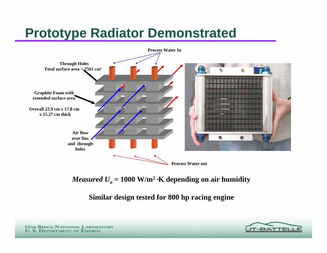
Prototype Radiator DemonstratedProcess Water In
Process Water out
Graphite Foam with extended surface area
Overall 22.9 cm x 17.8 cm x 15.27 cm thick
Air flow over fins
and through holes
Through HolesTotal surface area = 7561 cm2
Measured Uo = 1000 W/m2 ·K depending on air humidity
Similar design tested for 800 hp racing engine
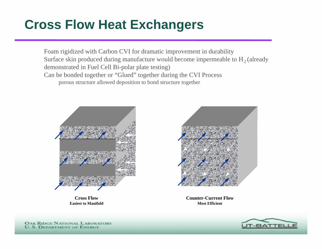
Cross Flow Heat Exchangers
Foam rigidized with Carbon CVI for dramatic improvement in durabilitySurface skin produced during manufacture would become impermeable to H2 (alreadydemonstrated in Fuel Cell Bi-polar plate testing)Can be bonded together or “Glued” together during the CVI Process
porous structure allowed deposition to bond structure together
Cross FlowEasiest to Manifold
Counter-Current FlowMost Efficient

Heat Resistant Composites
Standard Polymer Foam/Polymer

Satellite Applications?Thermal Doubler Panel • Current concept spreads heat across
larger area & reduces temperature• Heat is rejected to space with T4
relationship• A very low through thickness thermal
conductivity of current carbon-carbon (20W/m·K) and honeycomb core limits heatrejection
• The higher through-thickness thermalconductivity of the foam (180 W/m·K) willincrease temperature on outside surface
• High temperature on outside surface willincrease radiation
• Smaller panel footprint, or moreelectronics can be utilized.
C/C panel
Structural Panel
High PowerElectronics

Licensee - Poco Graphite, Inc.
• Leading manufacturer of premium, specialtygraphites and silicon carbides
• Over 35 years experience in the following majormarkets
• General Industrial• Aerospace• Biomedical• Semiconductor
• Texas based manufacturing with offices in Illinoisand France
• Applications Engineers based throughout US• Applications Engineers in France, Germany, Italy
and Singapore

POCO Capabilities
• Materials manufacturing facilities• Design Engineering• Machining expertise to produce finished parts
• In process and finished parts inspection and certification
• Post processing facilities for infiltrations,impregnations, purifcation of materials
• Laminations and bonding
• R & D Laboratories for materials testing anddevelopment

PocoFoam Time Line
• June 1999 - Poco Graphite, Inc. acquired theexclusive license to manufacture ORNLdeveloped foam
• Agreement includes field of use license for finished productsincludingw Heat exchangers
w Cooling systems or heat sinks for aerospace, chemical-process, glass, ceramicand medical industries
• April 2000 - Pilot production at POCO began• May 2000 - First sale of PocoFoam material• October 2000 - Full production of PocoFoam
expected to begin• Future Developments
PocoFoam Availability
• Material is available for purchase• Sizes up to 10 x 10 x 1 1/2” are in stock
• Pricing curve is consistent with developmental materials• Alliances are being made with developmental partners