high volt pulsed dc stimulator - amrexusa.com€¦ · iv electrical muscle...
TRANSCRIPT

*Federal law (USA) restricts this device to sale by or on the order of a licensed practitioner licensed by the law of the state in whichhe practices to use or order the use of this device.
User's Guide
High Volt Pulsed DC StimulatorHV752*
Amrex®
electrotherapy equipmenta division of Amrex-Zetron, Inc.

AMREX® electrotherapy equipmenta division of Amrex-Zetron, Inc.641 East Walnut StreetCarson, California 90746(310) 527-6868Toll Free Customer Service (800) 221-9069Fax (310) 366-7343E-Mail: [email protected] Site: http://www.amrex-zetron.com
HV752 User's GuideHigh Volt Pulsed DC Stimulator
Revised February 2006
Copyright © Amrex-Zetron, Inc. 2005. All rights reserved.Printed in the United States of America
The following are registered or trademarked by Amrex:Amrex®SynchroPulse™SynchroSonic®Flextrode®

i
Thank you. . .for selecting the Amrex SynchroPulse HV752 High Volt Pulsed DC Stimulator. Webelieve that you will find this instrument to be versatile, dependable and userfriendly. The HV752 is designed for the application of high volt pulsed dc musclestimulation. The Amrex HV752 High Volt Pulsed DC Stimulator is a dual-channel,four-pad, electrical muscle stimulator that produces continuous, surge and reciprocaloutput with selectable pulse width, frequency, and surge/reciprocal durations.The electrical muscle stimulation may be applied separately or may be combinedwith ultrasound simultaneously through the ultrasound transducer using an externalAmrex SynchroSonic® U/50.
Your HV752 has been manufactured by a group of dedicated, highly trainedemployees who exemplify the sixty Amrex tradition, since 1935, of manufacturingtherapeutic equipment of the highest quality while supporting you with prompt,courteous customer service.
Upon receipt of your HV752, verify your accessories against the enclosed checklist. Promptly return the postage paid Registration Card to Amrex. Save the originalshipping carton and all packing materials.
Please carefully review this User’s Guide prior to operating the Amrex HV752 HighVolt Pulsed DC Stimulator. Should you have any questions regarding your newpurchase, or need assistance, telephone Amrex Technical Services at (800) 221-9069.
ii
Limited Warranty
Amrex-Zetron, Inc. (Manufacturer) warrants each instrument it manufactures to be free from defectsin material and workmanship under normal use and service for a period of two (2) years from thedate of purchase. This two year warranty extends only to the original purchaser and shall notapply to batteries, fuses, accessories or any instrument which has been subjected to misuse, neglect,accident or abnormal conditions of operation.
The Manufacturer's obligation under this warranty is limited to repairing or replacing, at theManufacturer's option, any instrument returned to the factory within two (2) years from the dateof purchase. If the Manufacturer determines that the product fails to conform to this warranty dueto misuse, alteration or abnormal condition of operation, including evidence that nonauthorizedpersonnel have attempted to repair the device, the instrument will be repaired at customers expense.This warranty is exclusive and in lieu of all other warranties, expressed or implied, including butnot limited to any other warranty of merchantability or fitness for any particular purpose.Manufacturer shall not be liable for any special, incidental or consequential damages, whether incontract, tort or otherwise.
Service and Shipping Information
Amrex Technical Services has a representative to assist you should your equipment require serviceor repair. It is necessary to obtain a Return Merchandise Authorization (RMA) number beforereturning equipment to the factory for warranty repair. Call our representative toll free (800) 221-9069. Damage, resulting from repairs made outside the factory, is not covered under the warranty.
To maintain original design specifications, your Amrex muscle stimulator must be calibrated andsafety tested on an annual basis. Amrex strongly recommends that servicing be referred to thefactory. Call toll free (800) 221-9069.
Save the original shipping carton and all packing materials to safely return Amrex equipment tothe factory for service; repair; annual calibration, electrical and mechanical safety check. Allaccessories, including the ac line cord, must be included with the returned instrument. The customeris responsible for all freight charges. The Manufacturer shall assume NO responsibility for damagein transit.

iii
Contraindications—Warnings—Precautions
THIS INSTRUMENT OPERATES ON 120 VOLTS AC, 60 Hz. (unless otherwise indicated on theunit) AND MUST BE PROPERLY GROUNDED FOR SAFETY. The three wire power cord with"hospital grade" plug should be connected to a GROUNDED AC wall receptacle. It is the personalresponsibility and obligation of the user to insure that this instrument is properly connected to theAC POWER source before use.
Warning–Risk of burns and fire. DO NOT use near conductivematerial such as metal bed parts or innerspring mattresses. Renewelectrode cables upon evidence of deterioration. Use of controls,adjustment, or performance of procedures, other than those specifiedherein, may result in hazardous exposure to electrical energy.
Important
AMREX Intensity Reset Circuit: The Amrex High Volt Pulsed DC Stimulator incorporates aunique safety reset function as part of the intensity controls. This is to prevent any sudden orinadvertent stimulation output to the patient in the event that:
• The High Volt Pulsed DC Intensity controls are not set to the 0/Reset position enabling theaudible/tactile "clicks" at power on, provided the power has been off for more than tenseconds
• The ac power is interrupted for more than ten seconds before power is restored
• The treatment period has ended and more than ten seconds has elapsed before power on
The High Volt Pulsed DC Intensity controls must be returned to the 0/Reset position enabling theaudible/tactile "clicks" before stimulation output can be activated.
Patient "Treatment Stop" Switch: When the patient "Treatment Stop" switch is activated, stimulatoroutput will be discontinued immediately. The Reset Intensities indicator light will illuminate.Stimulator output cannot be resumed until the High Volt Pulsed DC Intensity controls for ChannelA and Channel B are returned to the 0/Reset position enabling the audible/tactile "clicks" whichwill turn off the Reset Intensities indicator light. NOW the stimulator output can beactivated

iv
Electrical Muscle Stimulation—Contraindications
• Contraindicated for patients with cardiac demand pacemakers.
• Should not be used on cancer patients.
Electrical Muscle Stimulation—Warnings
• Long term effects of chronic electrical stimulation are unknown.
• Safety has not been established for the use of electrical muscle stimulation during pregnancy.
• Adequate precautions should be taken in the case of persons with suspected heart problems.
• Adequate precautions should be taken in the case of persons with suspected or diagnosedepilepsy.
• Do not stimulate over the carotid sinus nerves, especially in patients with a known sensitivityto the carotid sinus reflex.
• Severe spasm of the laryngeal and pharyngeal muscles may occur when the electrodes arepositioned over the neck or mouth. The contractions may be strong enough to close theairway or cause difficulty in breathing.
• Electrical muscle stimulators should not be applied transcerebrally.
• Electrical muscle stimulators should not be used over swollen, infected or inflamed areasor skin eruptions.
• Caution should be used in the transthoracic application of electrical muscle stimulators inthat the introduction of electrical current into the heart may cause arrhythmias.
• Electrical muscle stimulators should be kept out of the reach of children.
Electrical Muscle Stimulation—Precautions
Precautions should be observed:
• When there is a tendency to hemorrhage following acute trauma or fracture.
• Following recent surgical procedures when muscle contraction may disrupt the healingprocess.
• Over the menstruating uterus.
• Where sensory nerve damage is present by a loss of normal skin sensation.
Some patients may experience skin irritation or hypersensitivity due to the electricalstimulation or the conductive medium. The irritation can usually be reduced by use of analternate conductive medium or alternate electrode placement.
Skin irritation and burns beneath the electrodes have been reported with the use of electricalmuscle stimulators.

v
Table of Contents
Part 1Overview ................................................................................................................................ 1
Part 2Power Section ......................................................................................................................... 5
Part 3High Volt Pulsed DC Stimulation Modality .................................................................... 9
Part 4HV752 General Operation and Application Procedures ............................................... 19
General Operation High Volt Pulsed DC Stimulator Modality ............................................ 19
Application of Electrical Muscle Stimulation .......................................................................... 21
Adverse Effects - Shortwave Diathermy Interference ........................................................... 22
Electrical Muscle Stimulation—Indications ............................................................................. 23
Electrical Muscle Stimulation—Contraindications ................................................................. 23
Electrical Muscle Stimulation—Warnings ................................................................................ 23
Electrical Muscle Stimulation—Precautions ............................................................................ 24
HV752 in Combination with Ultrasound ................................................................................. 26
High Volt stimulation combined with the Amrex SynchroSonic U/50 Ultrasound ........... 26
Control Settings and General Operation ........................................................................ 26
Appendix ASpecifications ....................................................................................................................... 33
Appendix BReferences ............................................................................................................................. 35

vi

The layout of the HV752 panel is logically arranged into two major sections.These sections are : Power and High Volt Pulsed DC Stimulator.
Overview
HV752 User's Guide 1
Part 1AMREX

2 HV752 User's Guide
Part 1
In the illustration below, dashed lines surround each of the HV752's sections. Abrief description of each section follows the illustration. Parts 2 and 3 of this user'sguide contain detailed descriptions.

HV752 User's Guide 3
Overview
Power SectionUse the Power Section to activate the main ac power and set the treatment duration.The power will shut off and a bell will sound when the treatment is complete.
High Volt Pulsed DC Stimulator Modality SectionSet the intensity and monitor the output of High Volt Pulsed DC Stimulation withthe controls, connectors, lights and meter dials in this section of the panel. Selecteither Continuous, Surge or Reciprocal output using the Output Mode control. Selecteither Narrow, Medium or Wide pulse width using the Pulse Width control. Selectoutput on, output off and reciprocal durations using the Output On - seconds andOutput Off - seconds controls. Select the output frequency using the Frequency - ppscontrol. Select the polarity for the black output jacks using the Polarity control.

4 HV752 User's Guide
Part 1

Power Section
HV752 User's Guide 5
In the illustration below, dashed lines surround the HV752's power section.
Part 2AMREX
6 HV752 User's Guide
Part 2
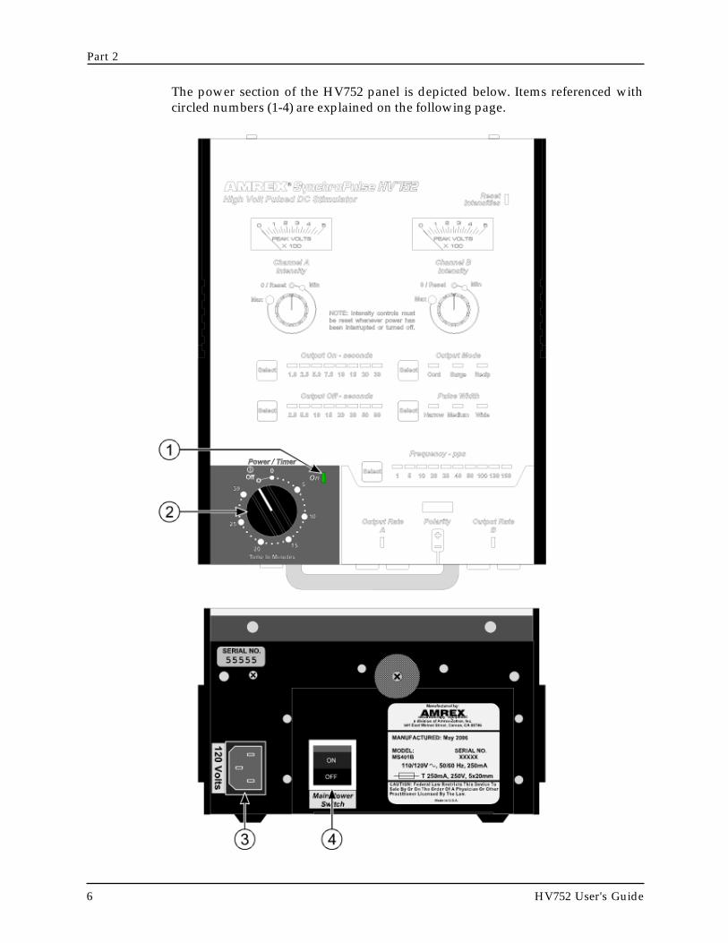
The power section of the HV752 panel is depicted below. Items referenced withcircled numbers (1-4) are explained on the following page.

HV752 User's Guide 7
Power Section
1. POWER / TIMER ON INDICATOR LIGHT: Illuminates when thePower/Timer switch is activated.
2. POWER / TIMER SWITCH: Controls the ac power as well as theduration of treatment. Rotate the Power/Timer knob clockwise pastthe ten-minute mark and then set it to the desired treatment duration.The On indicator light (located in the upper right corner of the Power/Timer section) will illuminate. The ac power will shut off and a bellwill sound when treatment is completed. To initiate early shut-off,rotate the Power/Timer knob counterclockwise to the Off position.The ac power will shut off and a bell will sound.
3. AC RECEPTACLE: Connection for the ac line cord.
4. MAIN POWER SWITCH: The HV752 is shipped with the MainPower Switch set at the Off position. The Main Power Switch must beset at the On position to enable ac power to be delivered to theHV752. This design feature allows the HV752 to maintain outputsettings from treatment to treatment.
Note: The HV752 is inoperable when the Main PowerSwitch is set at the Off position.

8 HV752 User's Guide
Part 2

HV752 User's Guide 9
In the illustration below, dashed lines surround the HV752's high volt pulsed dcstimulator section.
High Volt Pulsed DC Stimulator Modality
Part 3AMREX

HV752 User's Guide 11
High Volt Pulsed DC Stimulator Modality
5. OUTPUT OFF CONTROL: Selects a preset Output Off duration from 2.5through 90 seconds. The Output Off duration control is inoperable inContinuous and Reciprocal modes.
6. OUTPUT OFF INDICATOR LIGHT ARRAY: Indicates the selected OutputOff duration. The Output Off duration indicator light array is inoperable inContinuous and Reciprocal modes.
7. OUTPUT ON CONTROL: Selects a preset Output On duration from 1.0through 30 seconds in Surge mode. In Reciprocal mode, Selects a presetreciprocal rate from 1.0 through 30 seconds. The Output On duration controlis inoperable in the Continuous mode
8. OUTPUT ON INDICATOR LIGHT ARRAY: Indicates the selected OutputOn duration in Surge mode or the selected reciprocal rate in Reciprocal mode.The Output On duration indicator light array is inoperable in the Continuousmode.
9. CHANNEL A INTENSITY CONTROL: Regulates output for ChannelA from Min to Max. The Channel A Intensity meter will indicate the outputintensity selected in peak volts.
Note: The High Volt Intensity control for Channel A has a uniquereset circuit feature which prevents the practitioner from applyingone patient's intensity setting to another patient. The Amrex resetcircuit also allows the continuation or extension of the patient'streatment period if power is restored within ten (10) seconds.
10. CHANNEL A INTENSITY METER: Analog display of peak outputvoltage for Channel A. Ranges from 0 to 500 volts.
11. RESET INTENSITIES INDICATOR LIGHT: The Reset Intensities indicatorlight will illuminate in the event that:
• at power on, the Intensity controls are not set to the O/Resetposition enabling the audible/tactile "clicks"
• the Patient Treatment Stop Switch is activated
Note: To turn off the Reset Intensities indicator light, the Channel Aand Channel B Intensity controls must be returned to the O/Resetposition enabling the audible/tactile "clicks".
12. CHANNEL B INTENSITY METER: Analog display of peak outputvoltage for Channel B. Ranges from 0 to 500 volts.
HV752 User's Guide 13
High Volt Pulsed DC Stimulator Modality
13. CHANNEL B INTENSITY CONTROL: Regulates output for Channel Bfrom Min to Max. The Channel B Intensity meter will indicate the outputintensity selected in peak volts.
Note: The High Volt intensity control for Channel B has a uniquereset circuit feature which prevents the practitioner from applyingone patient's intensity setting to another patient. The Amrex resetcircuit also allows the continuation or extension of the patient'streatment period if power is restored within ten (10) seconds.
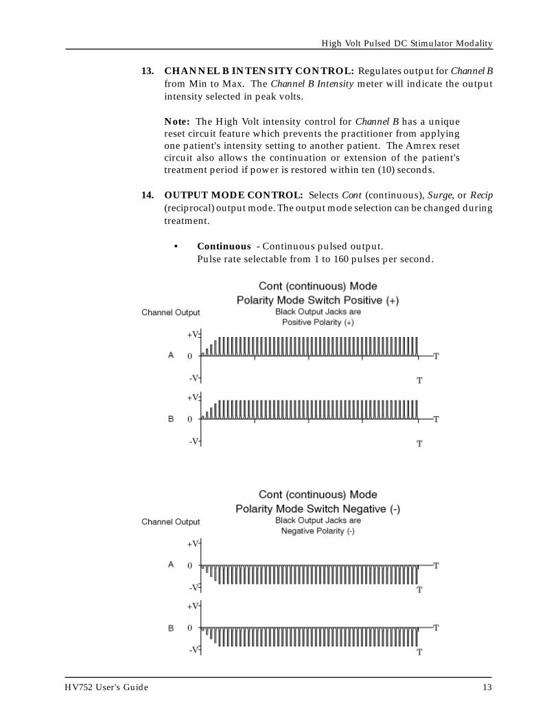
14. OUTPUT MODE CONTROL: Selects Cont (continuous), Surge, or Recip(reciprocal) output mode. The output mode selection can be changed duringtreatment.
• Continuous - Continuous pulsed output.Pulse rate selectable from 1 to 160 pulses per second.

HV752 User's Guide 15
High Volt Pulsed DC Stimulator Modality
14. CONTINUED - OUTPUT MODE CONTROL: Selects Cont (continuous),Surge, or Recip (reciprocal) output mode. The output mode selection can bechanged during treatment.
• Surge - Pulsed output surges simultaneously on Channel Aand Channel B.The Output On duration is selectable from 1 to 30 seconds.The Output Off duration is selectable from 2.5 to 90 seconds.

HV752 User's Guide 17
High Volt Pulsed DC Stimulator Modality
14. CONTINUED - OUTPUT MODE CONTROL: Selects Cont (continuous),Surge, or Recip (reciprocal) output mode. The output mode selection can bechanged during treatment.
• Reciprocal - Pulsed output alternates between Channel Aand Channel B.The reciprocal Output On duration is selectable from 1 to 30seconds.

HV752 User's Guide 19
High Volt Pulsed DC Stimulator Modality
15. OUTPUT MODE INDICATOR LIGHT ARRAY: Indicates the output modeselected.
16. PULSE WIDTH CONTROL: Selects the pulse width:
• Narrow 10 microseconds
• Medium 20 microseconds
• Wide 30 microseconds
Note: The pulse width can only be selected or changed when theintensity controls are in the O/Reset position.
17. PULSE WIDTH INDICATOR LIGHT ARRAY: Indicates the pulse widthselected.

HV752 User's Guide 21
High Volt Pulsed DC Stimulator Modality
18. FREQUENCY CONTROL: Selects a preset output frequency from 1 to 160pulses per second.
19. FREQUENCY INDICATOR LIGHT ARRAY: Indicates the outputfrequency selected.
20. POLARITY CONTROL: Selects the polarity for the black reference jackof Channel A and Channel B.
21. CHANNEL B OUTPUT INDICATOR LIGHT: Indicates the output isenabled and the output rate setting for Channel B.
22. CHANNEL B STIMULATOR OUTPUT JACKS: The referencestimulator output jack for Channel B is black. The other output jack forChannel B is red.
23. POLARITY INDICATOR LIGHT ARRAY: Indicates the polarity (+ or -) for the black reference jack of Channel A and Channel B.
24. CHANNEL A STIMULATOR OUTPUT JACKS: The referencestimulator output jack for Channel A is black. The other output jack forChannel A is white.
25. CHANNEL A OUTPUT INDICATOR LIGHT: Indicates the output isenabled and the output rate setting for Channel A.
26. TREATMENT STOP JACK: Connection for the Patient Treatment StopSwitch.
Note: When the Patient Treatment Stop Switch is activated, stimulatoroutput will be discontinued immediately.
• The Channel A and Channel B Intensity meters reduce to “O”
• The Reset Intensities indicator light flashes
• The Channel A and Channel B output indicator lights no longerilluminate
Note: Stimulator output cannot be resumed until the Channel A andChannel B Intensity controls are returned to the O/Reset position,enabling the audible/tactile "clicks", which turns off the ResetIntensities indicator light and turns on the Channel A and Channel BOutput indicator lights. The HV752 will maintain the treatmentsettings.
NOW the stimulator output can be activated.

24 HV752 User's Guide
Part 4
6. Hand the Patient Treatment Stop Switch to the patient and explain itsfunction.
Note: When the Patient Treatment Stop Switch button is pressed duringtreatment, stimulator output will be discontinued immediately.
• The Channel A and Channel B Intensity meters reduce to “0”
• The Reset Intensities indicator light flashes
• The Channel A and Channel B Output indicator lights no longerilluminate
Note: Stimulator output cannot be resumed until the Channel A and ChannelB Intensity controls are returned to the O/Reset position, enabling the audible/tactile "clicks", which will turn off the Reset Intensities indicator light. TheHV752 will maintain the treatment settings.
7. Rotate the Power / Timer control knob clockwise and set it to the desiredtreatment duration. The Power/Timer On and the default treatment settingindicator lights will illuminate. The factory default treatment settings are:
• Output mode Cont (continuous)
• Pulse Width Narrow
• Frequency 1 Pulse Per Second
• white reference jack polarity negative (-)
Note: When the desired treatment duration is less than ten (10) minutes,rotate the Power/Timer knob clockwise past the ten-minute markand then set it back to the desired treatment duration.
Note: If the Intensity controls are not in the O/Reset position, the ResetIntensities indicator light will flash. The Channel A and Channel B Intensitycontrols must be returned to the O/Reset position, enabling theaudible/tactile "clicks" before stimulator output can be enabled.
8. Press and release the Output Mode control until the Cont (continuous) outputmode is selected. The Output Mode indicator light array will indicate theoutput mode selected. The output mode selection can be changed at anytime during treatment.
Note: Always set the Channel A and Channel B Intensity levelswhile in the continuous output mode.

26 HV752 User's Guide
Part 4
15. Press and release the Output Off control to select a output off duration forthe Surge mode. (2.5, 5.0, 10, 15, 20, 30, 50, or 90 Seconds). The Output Offindicator light array will indicate the output off duration selected. TheOutput indicator lights for Channel A and Channel B will reflect the surge offduration selected.
Note: The Output Off control is disabled in the Cont and Recip modes.
16. When treatment is completed, stimulator output will be discontinuedimmediately.
• The Power/Timer switch shuts off and a bell sounds
• The output intensities reduce to “0” as indicated on the ChannelA and Channel B Intensity meters
• The indicator lights do not illuminate

28 HV752 User's Guide
Part 4
Adverse Effects - Shortwave Diathermy InterferenceIt is extremely important for the physiotherapist to have a clear understanding ofthe potential danger involved in the use of a low volt ac stimulator device in closeproximity to an active shortwave diathermy unit.
A medical shortwave diathermy unit is a very powerful transmitter of radio energy,the larger ones having an output of 500 watts. Any low volt ac stimulator devicewith external leads, in close proximity to a shortwave unit, is likely to be affectedby interference. This interference may be in the form of sparking between electrodesor between the leads and the device casing. The leads connecting the low volt acstimulator device to the patient can act as an aerial and collect the radio frequencyenergy from the shortwave unit. This could interfere with the operation of the lowvolt ac stimulator unit or affect internal functions of the device. Or, it could resultin the patient experiencing some unusual "surges" of current. There is no significantelectrical radiation from a low volt ac stimulator device.
The increasing electronic sophistication of physiotherapeutic equipment is likelyto mean that this problem is going to become more obvious. The minimum safeoperating distance is difficult to determine since local factors must be considered.At least two or three meters is needed between the nearest parts of either instrument,including the cables and electrodes. The low volt ac stimulator device does notneed to be plugged into a power supply to be affected by interference from ashortwave unit. Some very old types of shortwave generators seem to producemore interference than others which compounds the problem even further. Withsome shortwave units, the distance between devices of at least three meters maystill be inadequate.
In practice, shortwave diathermy units and low volt ac stimulator units should beplaced and operated as far away from each other as possible. It may be necessaryto screen off all shortwave units from other equipment or to have fully screenedrooms in which shortwave diathermy equipment can be operated without risk ofinterfering with other sensitive equipment. This is often difficult in a small practicewhere space is at a premium. In such cases, the units may have to be operated atdifferent times, not simultaneously. In all cases, it would be very dangerous togive shortwave diathermy and low volt ac stimulator treatment to a patientsimultaneously.
Any patient who reports a sudden, unexplainable "surge" in output may beexperiencing the effects of shortwave interference.

30 HV752 User's Guide
Part 4
Electrical Muscle Stimulation—PrecautionsPrecautions should be observed:
• When there is a tendency to hemorrhage following acute trauma or fracture
• Following recent surgical procedures when muscle contraction may disruptthe healing process
• Over the menstruating uterus
• Where sensory nerve damage is present by a loss of normal skin sensation
Some patients may experience skin irritation or hypersensitivity due to the electricalstimulation or the conductive medium. The irritation can usually be reduced byuse of an alternate conductive medium or alternate electrode placement.
Skin irritation and burns beneath the electrodes have been reported with the use ofelectrical muscle stimulators.

32 HV752 User's Guide
Part 4
HV752 in Combination with Ultrasound
The high voltage pulsed dc stimulation modality may be combined with anultrasound generator for simultaneous application through the ultrasoundtransducer. This technique involves using a large electrode pad and the ultrasoundtransducer. The transducer soundhead will become the active electrode whichwill transmit both ultrasound and electrical stimulation. Combination modesrequire specific control settings and pad arrangements.
High Volt stimulation combined with the Amrex SynchroSonic U/50Ultrasound
Control Settings and General Operation
1. Connect the female end of the power cord to the ac receptacle located atthe rear of the HV752. Connect the male end of the power cord to a properlygrounded 120 Vac, 60 Hz receptacle.
2. Connect the female end of the power cord to the ac receptacle located atthe rear of the U/50. Connect the male end of the power cord to a properlygrounded 120 Vac, 60 Hz receptacle.
3. Verify that the Main Power Switch, located on the back of the HV752, is setat the On position.
4. Connect the Patient Treatment Stop Switch to the HV752 Treatment StopJack.

34 HV752 User's Guide
Part 4
14. Rotate the U/50 Power / Timer knob clockwise and set it to the desiredtreatment duration. The Ultrasound On indicator light (located above theupper left corner of the Ultrasound meter) will illuminate.
Note: When the desired treatment duration is less than ten (10)minutes, Rotate the Power/Timer knob clockwise past the ten-minutemark and then rotate it counterclockwise to the desired treatmentduration.
15. Rotate the HV752 Power / Timer control knob clockwise and set it to the desiredtreatment duration. The HV752 Power/Timer On and the default treatment settingindicator lights will illuminate. The factory default treatment settings are:
• Output mode Continuous
• Pulse Width Narrow
• Frequency 1 Pulse Per Second
• black reference jack polarity negative(-)
Note: When the desired treatment duration is less than ten (10)minutes, Rotate the Power/Timer knob clockwise past the ten-minutemark and then rotate it counterclockwise to the desired treatmentduration.
Note: If the Intensity controls are not in the O/Reset position, the ResetIntensities indicator light will flash. The Channel A and Channel B Intensitycontrols must be returned to the O/Reset position, enabling the audible/tactile "clicks" before stimulator output can be enabled.
16. Verify that the HV752 Channel A and B Intensity controls are set at the 0/Resetposition.
17. Depress the U/50 Combination Mode switch to the On (in) position (the colorindicator will be visible).
18. Verify that the U/50 Ultrasound Intensity control is set at the "0" positionbefore removing the transducer from the cradle and placing the transducerfaceplate on the prepared treatment site.

36 HV752 User's Guide
Part 4
24. Slowly increase the HV752 Channel A Intensity control to the desired outputsetting. The Channel A Intensity meter will indicate the output intensity selected.Slowly increase the Channel B Intensity control to the desired output setting.The Channel B Intensity meter will indicate the output intensity selected.
Note: The output intensity setting can be changed at any time duringtreatment.
25. Press and release the Mode control in the Output / Waveform section to selectthe Cont, Surge, or Recip output mode. The Output Mode indicator lightarray will indicate the output mode selected.
Note: The output mode can be changed at any time during treatment.
26. Press and release the Surge ON control in the Surge Duration section to select asurge on duration for the Surge mode or a reciprocal rate for the Recipmode. (1, 2.5, 5.0, 7.5, 10, 15, 20, or 30 Seconds). The Surge On indicatorlight array will indicate the surge on duration or the reciprocal rate selected.The Channel A and Channel B Output indicator lights will reflect the surgeon duration or the reciprocal rate selected.
Note: The Surge ON control is disabled in the Cont mode.
27. Press and release the Surge OFF control in the Surge Duration section to select asurge off duration for the Surge mode. (2.5, 5.0, 10, 15, 20, 30, 50, or 90 Seconds).The Surge Off indicator light array will indicate the surge off duration selected. TheChannel A and Channel B Output indicator lights will reflect the surge off durationselected.
Note: The Surge OFF control is disabled in the Cont and Recip modes.
28. When treatment is completed, stimulator and ultrasound output will bediscontinued immediately.
• The Power/Timer switches shut off and the bells sound
• The output intensities reduce to “0” as indicated on the ChannelA, Channel B and Ultrasound Intensity meters.
• The indicator lights do not illuminate.
To initiate early shut off, turn both Power/Timer knobs counterclockwise to theOff position. The HV752 and U/50 ac power will shut off and the bells willsound. Reduce the HV752 Channel A and B Intensity controls to the 0/Resetpositions enabling the audible/tactile "clicks". Reduce the Ultrasound Intensitycontrol to the "0" position. Thoroughly clean the transducer faceplate beforeplacing the transducer in the transducer cradle. Thoroughly clean the dispersivesponge pad electrode with warm water.

Input Power Requirements
Line Voltage .............................. 120 Vac, 60 Hz(Special voltage available on request)
Current ...................................................... 0.25 A
Line Leakage......................................... < 50 µA
Electrical Stimulator
Waveform ..............................................................DC "needle" pulses with no parasitic spike
Output Voltage .......................... 0 to 500 peak V
Output Intensity ...................................................20µC max charge per pulse into 100 ohm load
Pulse Widthnarrow ..................................................... 10 µsmedium ................................................... 20 µswide .......................................................... 30 µs
Surge On Duration, Reciprocal On/Off Duration1.0, 2.5, 5.0, 7.5, 10, 15, 20, 30 s
Surge Off Duration ..............................................2.5, 5.0, 10, 15, 20, 30, 50, 90 s
Treatment Timer .... variable from 0 to 30 min
Timer Accuracy< 5 min................................................. ± 1 min5 to 10 min ............................................ ± 10%> 10 min ............................................... ± 1 min
Instrument
Overall Dimensions .... 8½" W x 10¾" D x 5" H
Weight ........................................................ 8 Lbs
Shipping Weight ..................................... 15 Lbs
Cleaning Instructions
1. Disconnect the power supply.
2. Use mild soap with a lightly moistened cloth.
3. Air dry before using.
Service and Shipping Information
Amrex Technical Services has a representativeto assist you should your equipment requireservice or repair. It is necessary to obtain aReturn Merchandise Authorization (RMA)number before returning equipment to thefactory for warranty repair. Call ourrepresentative toll free (800) 221-9069. Damage,resulting from repairs made outside the factory,is not covered under the warranty.
Your Amrex stimulator must be tested andcalibrated on an annual basis to maintain originaldesign specifications. Amrex stronglyrecommends that servicing be referred to thefactory. Call toll free (800) 221-9069.
Save the original shipping carton and all packingmaterials to ensure the safe return of yourAmrex equipment to the factory for service,repair, annual calibration, and electrical-mechanical check. All accessories, including theac line cord, must be included with the returnedinstrument. The customer is responsible for allfreight charges. The Manufacturer shall assumeNO responsibility for damage in transit.
Specifications
Appendix A
302010NARROW WIDEMEDIUM
MICROSECONDS
VOLTS
( 10K OHM LOAD )
300
500
0100
HV752 User's Guide 37

38 HV752 User's Guide
Appendix A

References
HV752 User's Guide 39
Alon, G. High Voltage Stimulation (High Voltage Pulsating Direct Current). ChattanoogaCorporation, Chattanooga, Tennessee, 1984.
Currier, D.P. and R.M. Nelson. Clinical Electrotherapy. Appleton and Lange, Norwalk,Connecticut, 1986.
Dyson, M. “Mechanisms Involved in Therapeutic Ultrasound”. Physiotherapy,March, Vol.73.3, pp.116-120, 1987.
Jaskoviak, P.A. and R.C. Schafer. Applied Physiotherapy. ACA Press, Arlington,Virginia, 1986.
Kahn, J. “Iontophoresis and Ultrasound for Post Surgical TMJ Trismus andParesthesia”. Physical Therapy, March 1980, 60:3.
Kahn, Joseph. Principles and Practice of Electrotherapy. Churchill Livingstone, NewYork, 1987.
Kleinkort, J.A. and F. Wood. “Phonophoresis with 1% Versus 10% Hydrocortisone”.Physical Therapy, 55:1320-1324, 1975.
Kottke, F.J., G.K. Stillwell and J.F. Lehman, ed. Krusen’s Handbook of Physical Medicineand Rehabilitation. W.B. Saunders Co., Philadelphia, 1982.
Michlovitz, S.L. and S.L. Wolf, ed. Thermal Agents in Rehabilitation. F.A. Davis Co.,Philadelphia, 1986.
Nix, W.A. and G. Vrbova. Electrical Stimulation and Neuromuscular Disorders.Springer-Verlag, Berlin, West Germany, 1986.
Nyborg, W.L. and M.C. Ziskin, ed. Biological Effects of Ultrasound. Vol. 16 of Clinicsin Diagnostic Ultrasound. Churchill Livingstone, New York, 1985.
Peat, Malcolm, ed. Current Physical Therapy. B.C. Decher, Inc., Philadelphia,Pennsylvania, 1988.
Appendix B

40 HV752 User's Guide
Appendix B