high voltage multifunction phasing stickkusamelectrical.com/manual/high voltage measuring...
TRANSCRIPT

G-17, Bharat Industrial Estate, T. J. Road, Sewree (W), Mumbai - 400 015. INDIA.Sales Direct.: 022 -2 4156638, Tel. : 022-24124540, 24181649, Fax : 022 - 24149659
Email : [email protected], Website : www.kusamelectrical.com
All Specifications are subject to change without prior notice
Chhaya com/D/chhaya/my documents/chhaya/backup/catlog/New catlog/KM-PC7K /PC11K /PC22K /PC33K /PC44K.cdr
HIGH VOLTAGE MULTIFUNCTION PHASING STICK
Model - PC7K / PC11K / PC22K / PC33K / PC44K
This NEW “PC” range of High Voltge Multifunction Phasing Stick
are :all - in - one,a Phase Comparator with colour code scale
indication, a Voltage Detector with Neon Indication & a Scaled
analog Voltmeter. They are available in five models for
applications up to 44 kV systems(6.6kV,11kV, 22kV, 33kV & 44 kV ).
These Dual Poles instruments incorporate modern, high quality
glass fibre front end,composite polyurethane main body molding
to give tough and very light weight construction and superior
Safety features. They have analogue Colour Coded Dual Scales
and Neon indication.
They are VDE0681part 5 compliant and IEC1243 - 2.
They are practical and efficient.Because of their multifunction
capabilites, you do not need to buy separate instruments, you
can therefore stay within your budget without compromise.
Fiberglass is of hot stick quality and tested to IEC specs(100kV /
300mm for 1min). All front end (resistors) are encapsulated.
These analog Multifunction phasing Sticks are ideally suited for
testing of grounded or ungrounded systems. Important
applications include checking voltage fuses,testing for correct
phase connections, and for absence of high voltage on de-
energized lines or apparatus. The dual scale read direct(no
multiplier)in kV AC or in % of full scale and colour coded(Green =
in phase; Red = out of phase). A Bright neon is included on the
scale for easy visibility indoor and it has dual purpose.
They are supplied complete with instruction manual. They are
housed in a superb High quality modern Plastic Case with
shock absorbing foam . They are suitable for indoor and
outdoor use (in dry weather).
They do not require dismantling or re-assembling and do not have
any user’s assembled parts, so eliminating the risks of assembly
mistake and accidents during High Voltage Work. In a breakdown
situation they are lighter than any other sticks available in the market
today. The indicator has been screened for high immunity to
interference fields. They determine the voltage and positively
identify phases up to 44kV.
They are equipped with two fixed - length poles connected by a
strong flexible, insulated cable.Hand guards are standard on all
models. They are easy to handle, light weight,well insulated and
designed to ensure maximum operator safety.
— Dual Colour Code Scale (%,Vac). Neon indicator lit when >1200 Vac. Compare between Phases.
— Measure and test Phase to Earth. — High Quality Fibreglass wound Rod. — Self powered operation - No Battery.
— DC version available.(Optional) — Measure Phase to Phase. — High immunity to interference fields.
— Suitable for indoor and outdoor use. — Current is limited to ±1 mill - ampere. — Voltage colour code - O-Y-G-B-R.
— Light weight Robust & Compact. — Designed to Exceed VDE 0681 part 5. — Meets IEC 61481 : 2001
— Carry Case included.
— —
SPECIAL FEATURES:
SCALES
0
0
16
32
48
AC
KV
%
50
100
PC 44k
0
0
12
24
36
AC
KV
%
50
100
PC 33k
0
0
8
16
24
AC
KV
%
50
100
PC 22k
0
0
4
8
12
AC
KV
%
50
100
PC 11k
0
0
2.7
5.3
8
AC
KV
%
50
100
PC 7k
6.6 kV 11 kV 22 kV 33 kV 44 kV
8 kV 12 kV 24 kV 36 kV 48 kV
9 kV 15 kV 30 kV 40 kV 55 kV
SPECIFICATIONSElectrical PC 7K PC 11K PC 22K PC 33K PC 44K
System Voltage
4.48 MW
<1 Sec
1.5 kV
Full Scale Voltage
Maximum Voltage
Total Resistance
Response time
Neon ThresholdNeon Lit Fully@ 1.5 kV 1.5 kV 1.5 kV 1.5 kV
1.2 kV 1.2 kV 1.2 kV 1.2 kV 1.2 kV
<1 Sec <1 Sec <1 Sec <1 Sec
6.78 MW 10.82 MW 19.68MW 26.8 MW
Recommended to use High Voltage gloves & insulating met for additional safety.
Operating Temperature
Operating Humidity-25°C to 55°C
20 to 96%RH
ENVIRONMENTAL
Mechanical PC 7K PC 11K PC 22K PC 33K PC 44K
Length of Handle 775 mmLength Front End 400mm 400mm 500mm 665mm 820 mmTotal length 1.175M 1.175M 1.275M 1.440M 1.595MTotal Weight 2.1Kg 2.1Kg 2.2Kg 2.4Kg 2.5KgHandle Material Composite Material with Polyurethane
Front End Fibre Glass Wound Tubing
775 mm 775 mm 775 mm 775 mm
An ISO 9001:2008 Company
®
OPTIONAL ACCESSORIES :
Piercing Tip 40mm(Optional)TER-40mm
Piercing Tip 70mm(Optional)TER-70mm
Right Angle AdaptorsIt can be semi-disconnected
for storage into the case.(Optional)- sold by pair
PC-160
ADP-PCXXK(Optional)
TER-213 100mmTER-213 60mmTER-213 40mm
(Optional)
An ISO 9001:2008 Company
®

HIGH VOLTAGEPHASE COMPARATORS
PC SERIESDOUBLE POLES
Model System Voltage Full Scale
PC7kPC11kPC22kPC33kPC44k
6.6KV11KV22KV33KV44KV
8KV12KV24KV36KV48KV
OPERATION MANUAL
AN ISO 9001:2000 COMPANY

-1-
INDEX PAGE
SAFETY RULES............................................. 1
GENERAL DESCRIPTION............................. 2
PRINCIPLE OF OPERATION......................... 2
PROVING THE PHASE COMPARATORS..... 3
LIMIT MARK................................................... 3
LABELS AND MARKING................................ 4
RANGE OF MODELS..................................... 5
INSTRUCTION FOR USE.............................. 6
OPERATION................................................... 7
SPECIFICATIONS.......................................... 8
SCALES.......................................................... 9
DIRECTIONS FOR USE................................. 10
TESTING FOR PHASING PRESENCE.......... 11
CARE AND MAINTENANCE.......................... 12
NOTES............................................................ 13
LIMITED WARRANTY..................................... 14
SAFETY RULES• Only Personnel who are fully trained in the use of High Voltage
Phase Comparators should use this equipment.• Be aware that the system that it will be used on are powered from
high voltages which are lethal.• Before use, ensure that the Phase Comparators and any
accessories are clean, free from cracks or deep scores, and are properly secured together.
• Only the proper rated Phase Comparators must be used. Ensurethat the Phase Comparator is properly rated for the voltage of thesystem under test.
• Test the operation of the Phase Comparator before and aftereach test.
• Do not allow any part of the Phase Comparator except the contactelectrodes to come in contact with energized or earthed items.
• Safe Working distance must always be observed.• Safety insulated Gloves and protective clothing and glasses
must be wear when using the Phase comparator.• The Phase Comparator must only be handled by one person
Only.• Do not insert the Phase Comparator beyond it’s limit mark into
the apparatus under test. The Limit mark is the red band.• The Phase Comparator should not be used as a synchronising
Device or a voltage detector.• The Interconnecting lead/cord must not be allowed to come
within 100mm (10cm) of the hand guard and must not be touchedwhile testing.
• Before using the Phase Comparator in the testing of factory assembled swtichgear, the manufacturer of the switchgear mustbe consulted as the suitability of the Phase Comparator in suchtesting.
• Always check for Phase Presence before testing between Phases. Ensure that voltage is present on both phases before testing between phases.
• The Phase Comparators are not to be subjected to a constant voltage for a period longer than 1 minute in every five minutes.

-2- -3-
GENERAL DESCRIPTION• The range of high Voltage Phase Comparators have been designed
to comply and exceeds the requirements of VDE0681Part5.• The Phase Comparators are double poles devices which are used
to determine the correct Phase Relationship between twoenergized conductors of the Same nominal Voltage and Frequency.
• Models are available to cover systems voltages from 1kV to 44kV50/60Hz.
• For other systems voltage, please contact the factory.• All models may be used indoor and outdoors in dry weather only.
PRINCIPLE OF OPERATION• The PC range of Phase Comparators is a resistive devise which
comprise mainly of resistors, a neon and a panel meter. The PhaseComparator draw current from the circuit or source under test.
• The Phase Comparator consist of two inter-connected poles (themaster pole with the panel meter and the slave pole).
• The Master pole carries the panel meter with the color coded scaleand the integral neon light indicator.
• The color coded scale indicates “in-phase/out-of-phase” band onthe scale. (Green = in-phase; Red=out-of-phase).
• The Neon light lit up when the voltage between the poles is greaterthan ±1.2kV ±1.5kV.
• If two energized conductors are out-of-phase and a contact electrode is touched onto each pole, current will flow between theconductors through the resistors (resistors are inside the fiberglassfront end in each pole) in the poles and the interconnecting lead/cord. This will cause the neon to lit and the panel meter’sindicator to move into the out-of-phase area (Red).
• If two energized conductors are in-phase and a contact electrode istouched onto each pole, current will not flow between the conductors through the resistors in the poles and theinterconnecting lead/cord. This should not cause the neon to lit andthe panel meter’s indicator to move. The indicator will stay into thein-phase area (Green).
• Ensure that voltage is present on both phases before testingbetween phases.
PROVING THE PHASE COMPARATORS• Before and after using a Phase Comparator and accessories, a
functional test should be performed on the Phase Comparator as it is to be used on the source or circuit to Test.
• A High Voltage Insulation tester can be used for this purpose.• When using a High Voltage Insulation tester, the Phase Comparator
will indicate the voltage generated by that H.V. Insulation tester.• Please note that H.V. Insulation testers are generating DC voltage
and have polarity.• The PC range of Phase Comparators are using a ½ bridge rectifier
and current only pass one way into the panel meter. However, theneon must lit both ways.
• When proving with a DC source as with a H.V. Insulation tester, the poles must be tested for both polarity to confirm that the panelmeter only show voltage in one way, but confirm that the neonindicates both polarity.
• The reading on the High Voltage Insulation tester also indicate thetotal value of the resistor chain and is also a good indication thatthe circuit is still correct and in good condition (See specifications).
• A Proving Unit can also be used if a High Voltage Insulation Meteris not available. The Proving unit does not indicate how many mega ohms are in the front end or if the circuit is still in goodcondition or not. The Proving unit only output a DC voltage of5kVdc.
LIMIT MARK• Each Phase Comparator has two poles.• Each pole has a front end which is in Fiberglass tubing.• Each pole has an Handle section.• At the junction between the handle section and the front end
section, there is a RED BAND which is the limit mark.• By definition, this mark, or the Red Band, indicates the physical
limit to which the poles of the Phase Comparators may be inserted between live components or may touch them.


-4- -5-
LABELS AND MARKING• The following labels must be present on the Master Pole.
• The following labels must be present on BOTH Poles.
The Phase Comparator willperform correctly overthe temperaturerangeof -25°C to + 55°C.
Read and Understand theInstruction manual before
using the Phase Comparator.The Phase Comparator is
designed for use onHigh Voltage Systems.
The Phase Comparator is designedto be used up to this voltage system only.
The Phase Comparator will operate over the frequencyrange 50 to 60 Hz.
The Phase Comparator is suitablefor use either indoor or outdoor indry condition
Voltage System forthis Phase Comparator
Part Number
The user must keep handsand all parts of the body behind the hand guard
to maintain safeworking distances.
CONFORMS TO DIN VDE 0681/5
NOT FOR USE IN RAIN
CAN BE USED AS A VOLTAGE TESTER
WARNING¡ISTAY BEHIND HAND GUARD
PHASECOMPARATOR
11kV
11kVPC 11k
Climatic Class - Normal Outdoor
50/60Hz
PHASECOMPARATOR
7kV
6.6kVPC 7k
Climatic Class - Normal Outdoor
50/60Hz
PHASECOMPARATOR
11kV
11kVPC 11k
Climatic Class - Normal Outdoor
50/60Hz
PHASECOMPARATOR
22kV
22kVPC 22k
Climatic Class - Normal Outdoor
50/60Hz
PHASECOMPARATOR
33kV
33kVTPC 33k
Climatic Class - Normal Outdoor
50/60Hz
PHASECOMPARATOR
33kV
33kVPC 33k
Climatic Class - Normal Outdoor
50/60Hz
PHASECOMPARATOR
44kV
44kVPC 44k
Climatic Class - Normal Outdoor
50/60Hz
DANGER: USE ON SYSTEMS UP TO6.6kV ONLY AS PER INSTRUCTION MANUAL
6.6kVDANGER: USE ON SYSTEMS UP TO
11kV ONLY AS PER INSTRUCTION MANUAL
11kVDANGER: USE ON SYSTEMS UP TO
22kV ONLY AS PER INSTRUCTION MANUAL
22kVDANGER: USE ON SYSTEMS UP TO
33kV ONLY AS PER INSTRUCTION MANUAL
33kVDANGER: USE ON SYSTEMS UP TO
44kV ONLY AS PER INSTRUCTION MANUAL
44kV
• Care must be taken to observe the attached labels, which must not be removed. The labels warn of danger and to use only up to the rated voltage, as per instruction manual. The Labels “Frequency Range”, “Year of Manufacture”, “not to be used in the rain”, “not to be used as voltage tester” are self-explanatory and are to be strictly Observed.
RANGE OF MODELS• Models are available to cover system voltages from 1kV to 44kV
@50 or 60Hz.• Contact the factory for information on models suitable for other
voltages.• The following models are available as standard instruments:
Model System Voltage Full Scale Maximum DisplayN° Voltage Voltage Voltage Type===== ============ ======== ======== ======
NeonPC7k 6.6kV 8kV 9kV & Panel
Meter===== ============ ======== ======== ======
Neon PC11k 11kV 12kV 15kV & Panel
Meter===== ============ ======== ======== ======
NeonPC22k 22kV 24kV 30kV & Panel
Meter===== ============ ======== ======== ======
NeonPC33k 33kV 36kV 40kV & Panel
Meter===== ============ ======== ======== ======
Neon PC44k 44kV 48kV 55kV & Panel
Meter===== ============ ======== ======== ======

-6- -7-
INSTRUCTION FOR USE• Before using the Phase Comparator, clean the Front End
(FiberGlass) with a polymer polishing.• All models do not require batteries and are being signal driven
(current taken from the source or circuit under test) and do notrequire arming. However, it is recommended that a functionaltest be carried out using an High Voltage Insulation tester or a proving unit.
• To prove the Phase Comparator, set the voltage on the Proving unitor on the High Voltage Insulation tester, to suit the model of PhaseComparator. Turn the test ”ON” or the proving unit “ON”. The Neonshould lit (if the voltage if high enough) and the indicator shouldmove nearest the voltage measured.
• Reverse the poles of the Phase Comparator and check that anout-of-phase indication is given.
• They are no user serviceable parts on our range of Phase Comparators. Should the Phase Comparator become damaged,faulty or, suspect in any form, please consult with your nearest distributor to return it to the factory.
• There must be galvanic contact between the test electrodes andthe part of the installation under test and, no other part of the phaseComparator, except the electrodes, should be in contact withenergized or earthed parts, in order to ensure accuracy of thedisplay.
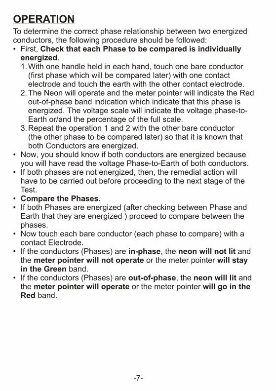
OPERATIONTo determine the correct phase relationship between two energized conductors, the following procedure should be followed:• First, Check that each Phase to be compared is individually
energized.1.With one handle held in each hand, touch one bare conductor
(first phase which will be compared later) with one contactelectrode and touch the earth with the other contact electrode.
2.The Neon will operate and the meter pointer will indicate the Redout-of-phase band indication which indicate that this phase isenergized. The voltage scale will indicate the voltage phase-to-Earth or/and the percentage of the full scale.
3.Repeat the operation 1 and 2 with the other bare conductor(the other phase to be compared later) so that it is known thatboth Conductors are energized.
• Now, you should know if both conductors are energized because you will have read the voltage Phase-to-Earth of both conductors.
• If both phases are not energized, then, the remedial action willhave to be carried out before proceeding to the next stage of theTest.
• Compare the Phases.• If both Phases are energized (after checking between Phase and
Earth that they are energized ) proceed to compare between thephases.
• Now touch each bare conductor (each phase to compare) with acontact Electrode.
• If the conductors (Phases) are in-phase, the neon will not lit and the meter pointer will not operate or the meter pointer will stayin the Green band.
• If the conductors (Phases) are out-of-phase, the neon will lit andthe meter pointer will operate or the meter pointer will go in the Red band.
-6- -7-
INSTRUCTION FOR USE• Before using the Phase Comparator, clean the Front End
(FiberGlass) with a polymer polishing.• All models do not require batteries and are being signal driven
(current taken from the source or circuit under test) and do notrequire arming. However, it is recommended that a functionaltest be carried out using an High Voltage Insulation tester or a proving unit.
• To prove the Phase Comparator, set the voltage on the Proving unitor on the High Voltage Insulation tester, to suit the model of PhaseComparator. Turn the test ”ON” or the proving unit “ON”. The Neonshould lit (if the voltage if high enough) and the indicator shouldmove nearest the voltage measured.
• Reverse the poles of the Phase Comparator and check that anout-of-phase indication is given.
• They are no user serviceable parts on our range of Phase Comparators. Should the Phase Comparator become damaged,faulty or, suspect in any form, please consult with your nearest distributor to return it to the factory.
• There must be galvanic contact between the test electrodes andthe part of the installation under test and, no other part of the phaseComparator, except the electrodes, should be in contact withenergized or earthed parts, in order to ensure accuracy of thedisplay.
OPERATIONTo determine the correct phase relationship between two energized conductors, the following procedure should be followed:• First, Check that each Phase to be compared is individually
energized.1.With one handle held in each hand, touch one bare conductor
(first phase which will be compared later) with one contactelectrode and touch the earth with the other contact electrode.
2.The Neon will operate and the meter pointer will indicate the Redout-of-phase band indication which indicate that this phase isenergized. The voltage scale will indicate the voltage phase-to-Earth or/and the percentage of the full scale.
3.Repeat the operation 1 and 2 with the other bare conductor(the other phase to be compared later) so that it is known thatboth Conductors are energized.
• Now, you should know if both conductors are energized because you will have read the voltage Phase-to-Earth of both conductors.
• If both phases are not energized, then, the remedial action willhave to be carried out before proceeding to the next stage of theTest.
• Compare the Phases.• If both Phases are energized (after checking between Phase and
Earth that they are energized ) proceed to compare between thephases.
• Now touch each bare conductor (each phase to compare) with acontact Electrode.
• If the conductors (Phases) are in-phase, the neon will not lit and the meter pointer will not operate or the meter pointer will stayin the Green band.
• If the conductors (Phases) are out-of-phase, the neon will lit andthe meter pointer will operate or the meter pointer will go in the Red band.

-8- -9-
SPECIFICATIONSElectrical
EMC Meets BS EN 50081-1 BS EN 50082-1
Exceeds DIN VDE 0681Part 5Exceeds IEC1243-2
PC7k PC11k PC22k PC33k Pc44kTotal Resistance ±3.95MW ±6.78MW ±13.5MW ±20.1MW ±27MWResponse time <1Sec <1Sec <1Sec <1Sec <1SecNeon Threshold 1.2kV 1.2kV 1.2kV 1.2kV 1.2kVNeon Lit Fully @ 1.5kV 1.5kV 1.5kV 1.5kV 1.5kV
MechanicalPC7k PC11k PC22k PC33k Pc44k
Lenght of Handle 765mm 765mm 765mm 765mm 765mmLenght of Front 340mm 340mm 460mm 610mm 760mmEnd (Fiberglass)Total Lenght 1.1M 1.1M 1.275M 1.395M 1.425MTotal Weight ±1.2kG ±1.2kG ±1.3kG ±1.4kG ±1.5kGHandle Material Composite Material with Polyurethane Front EndMaterial Fiber Glass Wound Tubing
Vibration Resistance: tested in accordance with IEC 68-2-6Drop Resistance: tested in accordance with IEC 68-2-32Bump: tested in accordance with IEC 68-2-2Impact: tested in accordance with IEC 1010 Clause 8.2Deflection: the contact electrodes must not deflect by more than 150mm when loaded at the electrode by 10N.Connection Lead.Cord Strenght: each pole connection to withstand 10000 swing with 10N Load applied and a vertical pull with 200N applied.
EnvironmentalOperating temperature:-25ºC to +55ºCOperating Humidity: 20 to 96% RH.
0
0
12
24
36
AC
KV
%
50
100
0
0
4
8
12
AC
KV
%
50
100
0
0
16
32
48
AC
KV
%
50
100
0
0
8
16
24
AC
KV
%
50
100
0
0
2.7
5.3
8
AC
KV
%
50
100
PC 33kPC 22kPC 7k PC 44kPC 11k
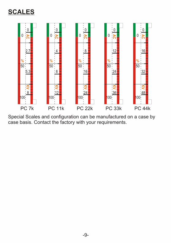
SCALES
Special Scales and configuration can be manufactured on a case by case basis. Contact the factory with your requirements.
-8- -9-
SPECIFICATIONSElectrical
EMC Meets BS EN 50081-1 BS EN 50082-1
Exceeds DIN VDE 0681Part 5Exceeds IEC1243-2
PC7k PC11k PC22k PC33k Pc44kTotal Resistance ±3.95MW ±6.78MW ±13.5MW ±20.1MW ±27MWResponse time <1Sec <1Sec <1Sec <1Sec <1SecNeon Threshold 1.2kV 1.2kV 1.2kV 1.2kV 1.2kVNeon Lit Fully @ 1.5kV 1.5kV 1.5kV 1.5kV 1.5kV
MechanicalPC7k PC11k PC22k PC33k Pc44k
Lenght of Handle 765mm 765mm 765mm 765mm 765mmLenght of Front 340mm 340mm 460mm 610mm 760mmEnd (Fiberglass)Total Lenght 1.1M 1.1M 1.275M 1.395M 1.425MTotal Weight ±1.2kG ±1.2kG ±1.3kG ±1.4kG ±1.5kGHandle Material Composite Material with Polyurethane Front EndMaterial Fiber Glass Wound Tubing
Vibration Resistance: tested in accordance with IEC 68-2-6Drop Resistance: tested in accordance with IEC 68-2-32Bump: tested in accordance with IEC 68-2-2Impact: tested in accordance with IEC 1010 Clause 8.2Deflection: the contact electrodes must not deflect by more than 150mm when loaded at the electrode by 10N.Connection Lead.Cord Strenght: each pole connection to withstand 10000 swing with 10N Load applied and a vertical pull with 200N applied.
EnvironmentalOperating temperature:-25ºC to +55ºCOperating Humidity: 20 to 96% RH.
0
0
12
24
36
AC
KV
%
50
100
0
0
4
8
12
AC
KV
%
50
100
0
0
16
32
48
AC
KV
%
50
100
0
0
8
16
24
AC
KV
%
50
100
0
0
2.7
5.3
8
AC
KV
%
50
100
PC 33kPC 22kPC 7k PC 44kPC 11k
SCALES
Special Scales and configuration can be manufactured on a case by case basis. Contact the factory with your requirements.
Main (Master) Stick
Protective Cover
Slave StickHand Grip
Insulating element
Interconnecting Lead
Master Stick Slave Stick
Resistif element
Hand Grip
Red Band (Limit Mark)
Hand Guard
Front End (Slave)
Front End (Master)
Split Probe(Contact electrode)
Contact Electrode(Split Probe)
Interconnecting Lead
Indicator Housing
M-S S-S
FEEDER “1” FEEDER “2”
FEEDER “1” FEEDER “2”
Phase “A” Phase “C”
Phase “B” Phase “B”
Phase “C” Phase “A”
-10- -11-
FEEDER “1” FEEDER “2”
M-S
S-S
Phase “A”
Phase “B”
Phase “C”
Earth
M-S
S-S
Phase “A”
Phase “B”
Phase “C”
Earth
M-S S-SPhase “A” Phase “A”
Phase “B” Phase “B”
Phase “C” Phase “C”
M-S S-S
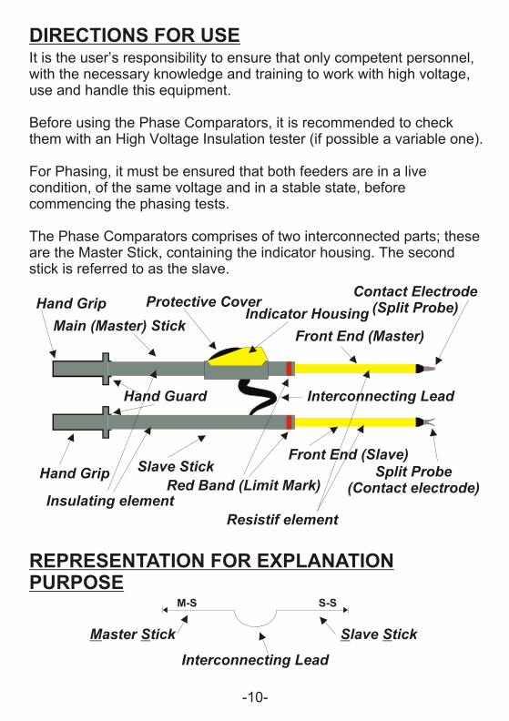
DIRECTIONS FOR USEIt is the user’s responsibility to ensure that only competent personnel, with the necessary knowledge and training to work with high voltage, use and handle this equipment.
Before using the Phase Comparators, it is recommended to check them with an High Voltage Insulation tester (if possible a variable one).
For Phasing, it must be ensured that both feeders are in a live condition, of the same voltage and in a stable state, before commencing the phasing tests.
The Phase Comparators comprises of two interconnected parts; these are the Master Stick, containing the indicator housing. The second stick is referred to as the slave.
REPRESENTATION FOR EXPLANATION PURPOSE
TESTING FOR PHASE PRESENCEBefore doing the Phase Comparison test, you must ensure that the feeders to be compared are live.
Example: Preparing toCompare two PhasesFrom different feeders
Check that both phases tobe compared are Live andhave the Same amplitude.
To Check Phase Presence,measure the Voltage betweenPhase and Earth. The result
will confirm that voltageis present and that the
amplitude are the same.
TESTING FOR PHASINGNo Indication - Neon OFF (does not lit) = IN PHASE
Indication - Neon ON (does lit) = OUT OF PHASE
Note that the links must be arranged so that the phases are connected in Phase, as indicated by the dotted lines.
Do Not Use Phasing Sticks unless you have been fully trainedIn High Voltage work and understand the system fully.

Main (Master) Stick
Protective Cover
Slave StickHand Grip
Insulating element
Interconnecting Lead
Master Stick Slave Stick
Resistif element
Hand Grip
Red Band (Limit Mark)
Hand Guard
Front End (Slave)
Front End (Master)
Split Probe(Contact electrode)
Contact Electrode(Split Probe)
Interconnecting Lead
Indicator Housing
M-S S-S
FEEDER “1” FEEDER “2”
FEEDER “1” FEEDER “2”
Phase “A” Phase “C”
Phase “B” Phase “B”
Phase “C” Phase “A”
-10- -11-
FEEDER “1” FEEDER “2”
M-S
S-S
Phase “A”
Phase “B”
Phase “C”
Earth
M-S
S-S
Phase “A”
Phase “B”
Phase “C”
Earth
M-S S-SPhase “A” Phase “A”
Phase “B” Phase “B”
Phase “C” Phase “C”
M-S S-S
DIRECTIONS FOR USEIt is the user’s responsibility to ensure that only competent personnel, with the necessary knowledge and training to work with high voltage, use and handle this equipment.
Before using the Phase Comparators, it is recommended to check them with an High Voltage Insulation tester (if possible a variable one).
For Phasing, it must be ensured that both feeders are in a live condition, of the same voltage and in a stable state, before commencing the phasing tests.
The Phase Comparators comprises of two interconnected parts; these are the Master Stick, containing the indicator housing. The second stick is referred to as the slave.
REPRESENTATION FOR EXPLANATION PURPOSE
TESTING FOR PHASE PRESENCEBefore doing the Phase Comparison test, you must ensure that the feeders to be compared are live.
Example: Preparing toCompare two PhasesFrom different feeders
Check that both phases tobe compared are Live andhave the Same amplitude.
To Check Phase Presence,measure the Voltage betweenPhase and Earth. The result
will confirm that voltageis present and that the
amplitude are the same.
TESTING FOR PHASINGNo Indication - Neon OFF (does not lit) = IN PHASE
Indication - Neon ON (does lit) = OUT OF PHASE
Note that the links must be arranged so that the phases are connected in Phase, as indicated by the dotted lines.
Do Not Use Phasing Sticks unless you have been fully trainedIn High Voltage work and understand the system fully.

-12- -13-
CARE AND MAINTENANCE• Storage: The Phase Comparator and it’s accessories should be
stored in the propietary carrying case/bag when not in use.
• Transporting: When the equipment is in transit it should be storedin its carrying case/bag. Whilst the equipment has been designedfor field use it should not be subjected to excessive bumps andshocks.
• Cleanliness: Dirt can cause surface tracking and it’s thereforenecessary to keep the Phase Comparator and its accessories cleanby washing them in mild detergent solution. All part should becleaned with the appropiate liquid.
• Mechanical Damage: If surface scratches or dents can easily beseen by the naked eye, then the equipment should be returned tothe factory of your nearest distributor for repairs since theseblemishes act as traps for dirt and moisture. Mechanical damagewould also necessitate the return of the equipment to themanufacturer.
• Recalibration and Proof Testing: Every twelve months the PhaseComparator and it’s accessories should be rechecked. This wouldinclude checking the threshold level of the neon, voltage prroftesting in factory or accredited laboratory and pressure testing ofthe panel meter housing.
Please note that there are no internal user replaceable parts.
The Phase comparator must always be clean and dry before useand during use. Please store the Phase Comparator in a dryPlace.
LIMITED WARRANTYWe warrant the product manufactured by us to be free from defective material or factory workmanship and agree to repair or replace this product which, under normal use and service, disclose the defect to be the fault of our manufacturing, with no charge for parts and service. If we are unable to repair or replace this product, we will make a full refund of the purchase price. Consult the user’s manual for proper instruction regarding use of this instrument. Our obligation under this warranty is limited to repairing, replacing or making refund of this test equipment which proves to be defective within forty eight months from the date of purchase.
This warranty does not apply to any of our products which have been repaired or altered by unauthorized persons in any way so as, in our sole judgement, to injure their stability or reliability, or which have been subject to misuse, abuse, misapplication, negligence or accident or which have had the serial numbers altered, defaced or removed.
All warranties implied by law are hereby limited to a period of fourty eight months, and the provisions of the warranty are expressely in lieu of any other warranties expressed or implied.
The purchaser agrees to assume all liability for any damages or bodily injury which may result from the use or misuse of the product by the purchaser, or it’s user, his employees, or others, and the remedies provided for in this warranty are expressly in lieu of any other liability we may have including incidental or consequential damages.
We reserve the right to discontinue models at any time, or change specification, price or design, without notice and without incuring any obligation.

G-17, Bharat Industrial Estate, T.J. Road,
Sewree(W), Mumbai-400 015. (INDIA)
Sales Direct: 91-22-24156638 Tel: 2412 4540, 2418 1649
Fax: 91-22-2414 9659 Email : [email protected]
Website: www.kusam-meco.co.in, www.kusamelectrical.com
NOTES
We exceeded the safety specifications wherever possible. However,we can’t be held liable for misuse or bad manipulation.We simplified the Phase Comparators by not having any parts to assembled on site. There is no user serviceable parts or user assembled part in our Phase Comparators.Only the tip (contact electrode) has to be screwed on the Front end ofeach pole. They generally do not need to be removed by the user.For other kind of tips and contact electrodes, contact the factory or you nearest distributor.Getting regular training on your High Voltage equipment and on theelectrical network / grid you are working on is a good practice and willhelp in keeping you safe.Always make a sketch before proceeding with testing High Voltage and ensure you are fully in control of the testing and understand fullywhat is going on. Failure to do so can result in fatal accidents.
-13-
LIMITED WARRANTY
Each “KUSAM-MECO” product is warranted to be free from defects in material
and workmanship under normal use & service. The warranty period is one year
(12 months) and begins from the date of despatch of goods. In case any defect
occurs in functioning of the instrument, under properuse, within the guarantee
period, the same will be rectified by us free of charges, provided the to and fro
freight charges are borne by you.
This warranty extends only to the original buyer or end-user customer of a
“KUSAM-MECO” authorized dealer.
This warranty does not apply for damaged IC’s, fuses, disposable batteries,
carrying case, test leads, or to any product which in KUSAM-MECO’s opinion,
has been misused, altered neglected, contaminated or damaged by accident or
abnormal conditions of operation or handling.
“KUSAM-MECO” authorized dealer shall extend this warranty on new and
unused products to end-user customers only but have no authority to extend a
greater or different warranty on behalf of “KUSAM-MECO”.
“KUSAM-MECO” warranty obligation is limited, at option, for free of charge
repair, or replacement of a defective product which is returned to a “KUSAM-
MECO” authorized service center within the warranty period.
THIS WARRANTY IS BUYER’S SOLE AND EXCLUSIVE REMEDY AND IS IN
LIEU OF ALL OTHER WARRANTIES, EXPRESS OR IMPLIED, INCLUDING
BUT NOT LIMITED TO ANY IMPLIED WARRANTY OF MERCHANTABILITY OR
FITNESS FOR A PARTICULAR PURPOSE OR USE. “KUSAM-MECO”
SHALL NOT BE LIABLE FOR ANY SPECIAL, INDIRECT, INCIDENTAL OR
CONSEQUENTIAL DAMAGES OR LOSSES, INCLUDING LOSS OF DATA,
ARISING FROM ANY CAUSE WHATSOEVER.
All transaction are subject to Mumbai Jurisdiction.
G-17, Bharat Industrial Estate, T.J. Road, Sewree(W), Mumbai-400 015. (INDIA)
Sales Direct: 91-22-24156638 Tel: 2412 4540, 2418 1649 Fax: 91-22-2414 9659
Email : [email protected] Website: www.kusamelectrical.com ,
www.kusam-meco.co.in