highjump advantage architect · 2016-12-02 · intro to advantage architect 11 online lessons:...
TRANSCRIPT

Getting Started: i
HighJump™ Advantage Architect Lab Exercises
Version 12.15 (with HighJump One 1.1.1)
December 2016

2
HighJump
(800) 328–3271
(952) 947–4088 in the Minneapolis/St. Paul metropolitan area
(952) 947–0440 (fax)
5600 W 83rd Street, Suite 600, 8200 Tower, Minneapolis, Minnesota 55437
www.highjump.com
© 2015 HighJump. All Rights Reserved.
This document and the software it describes are copyrighted properties of HighJump with all rights reserved. The documentation and software are confidential and a valid license from HighJump is required for possession and use. Neither this information nor the software may be copied in whole or in part without the prior written consent of the copyright owner. This document was created in the United States of America.
HighJump is a trademark of HighJump Software Inc. All other marks are the property of their respective owners.
HighJump warrants the software covered by this document only as stated in a legally binding license agreement between a customer and HighJump or one of its current or historic subsidiaries or affiliates.
This document is subject to change at the sole discretion of HighJump.
If this document and the software it describes are being acquired by or for the U.S. Government, or by any prime contractor or subcontractor (at any tier) under any prime contract, grant, cooperative agreement, or other transaction agreement with the U.S. Government, the following provisions apply: By accepting delivery of this software and information, the U.S. Government, prime contractor or subcontractor hereby agrees that this software qualifies as "commercial computer software" within the meaning of the applicable U.S. Government procurement or financial acquisition regulations and agency-specific supplemental regulations. The terms and conditions set forth above shall apply to the U.S. Government's use, duplication, modification, adaption, and disclosure of this document and the software it describes, and shall supersede any conflicting terms and conditions. If these terms and conditions fail to meet the U.S. Government's needs or are inconsistent in any respect with Federal law, the U.S. Government agrees to return this document and the software it describes, unused, to HighJump.

3
Table of Contents
Getting Started: ........................................................................................ 9
Introduction ........................................................................................................9
Background Information ....................................................................................9
Online Lessons: Intro to Advantage Architect .................................... 11
Introduction ......................................................................................................11
Background Information ..................................................................................11
Windows: Navigating in the Operating System ................................. 13
Introduction ......................................................................................................13
Background Information ..................................................................................13
Activity 1: Opening an Application ...........................................................14
Activity 2: Exiting the Start Window and the Apps Window ...................16
Architect Lab Exercise 1: Intro to Advantage Architect ..................... 18
Introduction ......................................................................................................18
Background Information ..................................................................................18
Activity 1: Understand the Current Process ...............................................19
Activity 2: Understand the Requirements ..................................................21
Activity 3: Develop the Changes ...............................................................22
Activity 4: Compile and Activate the Changes ..........................................27
Activity 5: Test the Changes ......................................................................30
Activity 6: Check in the Objects ................................................................31
Architect Lab Exercise 2: Call an Existing Process Object ............... 33
Introduction ......................................................................................................33
Background Information ..................................................................................33
Activity 1: Understand the Current Process ...............................................34
Activity 2: Understand the Requirements ..................................................35
Activity 3: Develop the Changes ...............................................................35
Activity 4: Compile and Activate the Changes ..........................................37
Activity 5: Test the Changes ......................................................................38
Activity 6: Check in the Objects ................................................................38
Architect Lab Exercise 3: Compare Actions ....................................... 40
Introduction ......................................................................................................40
Background Information ..................................................................................40

4
Activity 1: Understand the Current Process ...............................................41
Activity 2: Understand the Requirements ..................................................42
Activity 3: Develop the Changes ...............................................................42
Activity 4: Compile and Activate the Changes ..........................................48
Activity 5: Test the Changes ......................................................................49
Activity 6: Check in the Objects ................................................................50
Architect Lab Exercise 4: Calculate Actions ....................................... 51
Introduction ......................................................................................................51
Background Information ..................................................................................51
Activity 1: Understand the Current Process ...............................................52
Activity 2: Understand the Requirements ..................................................53
Activity 3: Develop the Changes ...............................................................53
Activity 4: Compile and Activate the Changes ..........................................75
Activity 5: Test the Changes ......................................................................76
Activity 6: Check in the Objects ................................................................78
Architect Lab Exercise 5: Display Text on the Reader ....................... 79
Introduction ......................................................................................................79
Background Information ..................................................................................79
Activity 1: Understand the Current Process ...............................................80
Activity 2: Understand the Requirements ..................................................83
Activity 3: Develop the Changes ...............................................................83
Activity 4: Compile and Activate the Changes ..........................................96
Activity 5: Test the Changes ......................................................................97
Activity 6: Check in the Objects ................................................................98
Admin Lab Exercise 6: Visual Debugger ............................................ 99
Introduction ......................................................................................................99
Background Information ..................................................................................99
Activity 1: Understand the Current Process .............................................100
Activity 2: Explore the Visual Debugger.................................................103
Activity 3: Add a Watch ..........................................................................109
Activity 4: Add a Breakpoint ...................................................................113
Activity 5: Use the Message Watch .........................................................117
Activity 6: Use the Record Feature ..........................................................120
Activity 7: View the Call Stack ...............................................................124
Activity 8: View a List .............................................................................127
Architect Lab Exercise 7: Add a New Business Process ................. 131
Introduction ....................................................................................................131
Background Information ................................................................................131

5
Activity 1: Understand the Current Process .............................................132
Activity 2: Understand the Requirements ................................................133
Activity 3: Develop the Changes .............................................................133
Activity 4: Compile and Activate the Changes ........................................166
Activity 5: Test the Changes ....................................................................167
Activity 6: Check in the Objects ..............................................................170
Architect Lab Exercise 8: Add a Database Column .......................... 171
Introduction ....................................................................................................171
Background Information ................................................................................171
Activity 1: Understand the Current Process .............................................172
Activity 2: Understand the Requirements ................................................174
Activity 3: Develop the Changes (Phase 1) .............................................174
Activity 4: Compile and Activate the Changes (Phase 1) ........................187
Activity 5: Test the Changes (Phase 1) ....................................................188
Activity 6: Develop the Changes (Phase 2) .............................................190
Activity 7: Compile and Activate the Changes (Phase 2) ........................204
Activity 8: Test the Changes (Phase 2) ....................................................205
Activity 9: Check in the Objects ..............................................................206
Architect Lab Exercise 9: Add a Prompt with Validation ................. 207
Introduction ....................................................................................................207
Background Information ................................................................................207
Activity 1: Understand the Current Process .............................................208
Activity 2: Understand the Requirements ................................................208
Activity 3: Develop the Changes (Phase 1) .............................................209
Activity 4: Compile and Activate the Changes (Phase 1) ........................222
Activity 5: Test the Changes (Phase 1) ....................................................223
Activity 6: Develop the Changes (Phase 2) .............................................226
Activity 7: Compile and Activate the Changes (Phase 2) ........................244
Activity 8: Test the Changes (Phase 2) ....................................................245
Activity 9: Develop the Changes (Phase 3) .............................................246
Activity 10: Compile and Activate the Changes (Phase 3) ......................250
Activity 11: Test the Changes (Phase 3) ..................................................251
Activity 12: Check in the Objects ............................................................252
Architect Lab Exercise 10: Function Keys ........................................ 253
Introduction ....................................................................................................253
Background Information ................................................................................253
Activity 1: Understand the Current Process .............................................254
Activity 2: Understand the Requirements ................................................255

6
Activity 3: Develop the Changes .............................................................255
Activity 4: Compile and Activate the Changes ........................................268
Activity 5: Test the Changes ....................................................................270
Activity 6: Check in the Objects ..............................................................272
Architect Lab Exercise 11: Display a List .......................................... 274
Introduction ....................................................................................................274
Background Information ................................................................................274
Activity 1: Understand the Current Process .............................................275
Activity 2: Understand the Requirements ................................................276
Activity 3: Develop the Changes .............................................................277
Activity 4: Compile and Activate the Changes ........................................287
Activity 5: Test the Changes ....................................................................288
Activity 6: Check in the Objects ..............................................................291
Admin Lab Exercise 12: Advantage Architect Applications ........... 292
Introduction ....................................................................................................292
Background Information ................................................................................292
Activity 1: Export an Advantage Architect Application ..........................293
Activity 2: Import an Advantage Architect Application ..........................300
Activity 3: Compile and Activate the Changes ........................................305
Activity 4: Test the Changes ....................................................................309
Activity 5: Restore the Original Application ...........................................310
Architect Lab Exercise 13: Cross Application Calls ......................... 315
Introduction ....................................................................................................315
Background Information ................................................................................315
Activity 1: Understand the Current Process .............................................316
Activity 2: Understand the Requirements ................................................317
Activity 3: Build a New Solution Environment .......................................317
Activity 4: Review the Report-Related Application ................................322
Activity 5: Develop the Changes .............................................................328
Activity 6: Compile and Activate the Changes ........................................336
Activity 7: Test the Changes ....................................................................338
Activity 8: Check in the Objects ..............................................................339
Architect Lab Exercise 14: Elevate the App Log Level..................... 340
Introduction ....................................................................................................340
Background Information ................................................................................340
Activity 1: Understand the Current Process .............................................341
Activity 2: Understand the Requirements ................................................342
Activity 3: Develop the Changes .............................................................342

7
Activity 4: Compile and Activate the Changes ........................................347
Activity 5: Test the Changes ....................................................................349
Activity 6: Check in the Objects ..............................................................351
Architect Lab Exercise 15: Write a Message to the Log ................... 352
Introduction ....................................................................................................352
Background Information ................................................................................352
Activity 1: Understand the Current Process .............................................353
Activity 2: Understand the Requirements ................................................354
Activity 3: Develop the Changes .............................................................354
Activity 4: Compile and Activate the Changes ........................................361
Activity 5: Test the Changes ....................................................................363
Activity 6: Check in the Objects ..............................................................363
Architect Lab Exercise 16: Initiate a Background Process .............. 364
Introduction ....................................................................................................364
Background Information ................................................................................364
Activity 1: Understand the Current Process .............................................365
Activity 2: Understand the Requirements ................................................365
Activity 3: Import, Compile, and Activate the Divert Application .........366
Activity 4: Review the Divert Application .............................................366
Activity 5: Build the Divert Table in the Database .................................368
Activity 6: Use Commander to Start a Background Process Object .......369
Activity 7: Test the Changes ....................................................................374
Architect Lab Exercise 17: Auto Launch Visual Debugger .............. 375
Introduction ....................................................................................................375
Background Information ................................................................................375
Activity 1: Understand the Current Process .............................................376
Activity 2: Understand the Requirements ................................................376
Activity 3: Develop the Changes .............................................................377
Activity 4: Compile and Activate the Changes ........................................382
Activity 5: Test the Changes ....................................................................384
Activity 6: Revert the Changes ................................................................384
Activity 7: Check in the Objects ..............................................................385
Architect Lab Exercise 18: Challenge Exercise ................................ 387
Introduction ....................................................................................................387
Background Information ................................................................................387
Activity 1: Understand the Current Process .............................................388
Activity 2: Understand the Requirements ................................................389
Activity 3: Development Overview .........................................................391

8
Activity 4: Add the Process to the Menu Structure .................................392
Activity 5: Add the Dialogs to the Process ..............................................394
Activity 6: Add the Serial Number Table ................................................398
Activity 7: Add the Serial Number Validation ........................................399
Activity 8: Add the Looping Logic ..........................................................401
Activity 9: Insert a Row into the Transaction Log ..................................403
Activity 10: Add the F1 Logic .................................................................404
Activity 11: Add Text to the Serial Number Dialog ................................406
Activity 12: Write Entry to the Platform Log ..........................................408
Activity 13: Full Unit Test .......................................................................409

Getting Started: 9
Getting Started:
Introduction This section consists of the following:
How to use this manual
Utilizing additional online lessons
Getting help from an instructor
Providing feedback
Background Information How to use this Manual: This manual contains self-directed exercises for the HighJump Software Advantage Architect VLab and instructor-led classes. Each exercise contains several hands-on activities. The exercises are designed to stand alone but the activities that make up the exercise tend to build upon each other. Please print this manual and keep it for future reference. Each step in an activity is preceded by a check box. Many students find it helpful to check off each step as they progress in order to track their progress. If an exercise is not working, check your steps before contacting HighJump. Most errors are caused by a missed procedural step somewhere along the activity. It is recommended that the exercises be completed in the order they are presented.
Utilizing additional Online Lessons and help files:
Several exercises contain links to pertinent online lessons that include explanations, video demonstrations, and simulations to assist your learning. References to the online lessons are preceded by this icon (left) in the manual. If you are taking an instructor-led class, you can bypass these online lessons as they were included in the pre-work. If you are taking a VLab class, then these online lessons serve as supplemental
training to aid your learning. To access the online lessons, click the Pre-Work: Advantage Architect link or the Architect Online Lectures link in the panel on the right side of the VLab environment.
These online lessons are available 24/7 to customers with an eLearning subscription.

Getting Started: 10
Getting help from an instructor If you need to contact an instructor, click the Ask an Instructor button in the panel on the right side of VLab environment.
Providing feedback When you complete the course, please fill out the online evaluation. It is completely anonymous and will help HJU improve its training deliverables. You can access the online evaluation by clicking on the Evaluate HJU VLabs button in the panel on the right side of the VLab environment.

Online Lessons:
Intro to Advantage Architect 11
Online Lessons: Intro to Advantage Architect
Introduction This section provides you with an introduction to the Advantage Architect tool through the use of online lessons.
Background Information Advantage Architect is the HighJump tool used to adapt the Advantage base application to the business processes of a company. In a HighJump solution, these business processes take the form of process objects. Using Architect, you can create new process objects or modify existing ones to suite your individual business needs.
Before performing the exercises in this manual, it is essential that you obtain some background instruction on the Architect tool and how process objects work. In the instructor-led class, the background information is delivered via lectures. In the VLab class, the background information is delivered via online lessons. The online lessons below provide a solid foundation for understanding the Advantage Architect tool.

Online Lessons:
Intro to Advantage Architect 12
Activity 1: Navigate Advantage Architect
Before you make changes to any of the applications you need to understand how to navigate in the tool. This lesson demonstrates some of the important navigation features of Advantage Architect.
1. Open the Advantage Architect online course.
2. Review the Start Architect and Connect to Repository topic
3. Review the Tour of Work Environment topic
4. Review the Working with Objects topic.
5. Review the Additional Usability Features topic.
Activity 2: Introduction to Process Objects
At the heart of Advantage Architect development is the concept of a process object. A process object is a collection of objects and actions that perform a specific function. At a very rudimentary level, a process object is like a procedure in other formal development languages. Before you make changes to any of the application, it is important to understand the concept of a process object, and a little bit about how to interact with them in the tool.
1. Open the Architect Online Lectures.
2. Review the Day 1 | Building Blocks – Process Objects topic.
Activity 3: Compile and Activate an Application
After you make changes to the application, you need to push those changes out to the terminals. The process of pushing out these changes is called compiling and activating. This lesson demonstrates how to compile and activate an Advantage Architect application.
1. Open the Advantage Architect online course.
2. Review the Compilation and Activate Application topic.
Activity 4: Day 1 Lectures
The lectures from the class with a live instructor are posted online. The Day 1 lectures give a broad overview of the various object types that are used in Advantage Architect
1. Open the Architect Online Lectures online course.
2. Review all Day 1 lectures.

Windows:
Navigating in the Operating System 13
Windows: Navigating in the Operating System
Introduction This exercise consists of the following activities:
1. Opening an Application
2. Exiting the Start Window and the Apps Window
Background Information This class utilizes the Windows Server 2012 R2 operating system. This operating system is not as intuitive as some of the previous versions. Due to some of the fundamental changes introduced by Microsoft, this exercise demonstrates some of the basic operations within the operating system. Additionally, it introduces the language used in this manual to describe these basic operations.

Windows:
Navigating in the Operating System 14
Activity 1: Opening an Application
Procedures: The procedures below demonstrate how to open an application in the operating system.
Look in the lower left corner of the main window.
The traditional “Start” button that appeared in previous versions of the operating system has been replaced by the modern Windows icon. Although the icons are different between the traditional version and the newer one, both buttons function in a similar manner.
Even though the “Start” text no longer appears on this button, this manual will refer to it as the “Start” button.
Click the Start button.
The traditional “Start” menu that appeared in previous versions of the operating system has been replaced by a modern, paneled look. While this window has some similar features to the traditional “Start” menu, it has some added capabilities as well.
Look in the lower left corner of the Start window.

Windows:
Navigating in the Operating System 15
There is an arrow icon inside of a white circle. This button functions similarly to the traditional “All Programs” menu under the Start menu in previous versions.
Even though the “All Programs” text no longer appears on this button, this manual will refer to it as the “All Programs” button.
Click the All Programs button.
The system displays a list of all applications installed on the machine in the Apps window. This list is comparable to the applications that appeared under the All Programs menu in previous versions. The options in white are the application names. The text that appears in blue are the grouping names which is comparable to the folder names in previous versions.
When an instruction in this manual directs you to open a new application, it will include both the grouping name and the application name. The instruction will look similar to “Click the Administrative Tools | Task Scheduler menu option”
Use the horizontal scroll bar to scroll all the way to the right.
Click the Windows Accessories | Calculator menu option.
The system closes the Apps windows and launches the calculator application.

Windows:
Navigating in the Operating System 16
Activity 2: Exiting the Start Window and the Apps Window
Procedures: The procedures below demonstrate how to return to the desktop if you are in the Start Window or the Apps Window.
The desktop is where you can view the applications that are running. In this example you can see the calculator application running on the desktop.
Click the Start button.
The system displays the paneled Start window.
While there are a couple different ways of returning to the desktop if you are on the Start window, the easiest method is to utilize one of the preconfigured panels.
Click the Desktop panel that appears immediately below the Administrative Tools panel and the File Explorer panel.

Windows:
Navigating in the Operating System 17
The system returns to the desktop and displays the calculator application.
Next you will navigate to the Apps window and then return to the desktop.
Click the Start | All Programs button.
The system displays the Apps window.
While there are a couple ways of returning to the desktop from the Apps window, the easiest method is to leverage the escape key.
Press the Escape key.
The system returns to the desktop and displays the calculator application.
Close the Calculator application.

Architect Lab Exercise 1:
Intro to Advantage Architect 18
Architect Lab Exercise 1: Intro to Advantage Architect
Introduction This exercise emphasizes the following components of Advantage Architect
1. Starting the tool.
2. Checking out objects.
3. Modifying objects.
4. Checking in the objects.
5. Compiling and activating the application.
The skills in this first exercise provide the basis for making any change in the Advantage Architect tool. You will repeat these steps several times throughout the course of this lab. Likewise, you will repeat these steps any time you need to make a change in your own development environment.
Background Information This exercise uses the Logon business process as the basis for all activities. The system directs the user through the Logon process when the user initially turns on an RF terminal. The system captures a user ID, a password, and a forklift. Then it displays a menu of business processes which the user can execute.
While the focus of this class is on the Advantage Architect tool, it helps to have a little bit of knowledge around the Advantage Workflow Engine. The Advantage Workflow Engine is similar to the engine in an automobile. If the car engine is running, you can travel to other destinations. If the car engine is not running, then you can only sit in the garage and listen to the radio. Similarly, if the Advantage Workflow Engine is running, then the HighJump system is running, and you can execute the full suite of business processes like receiving, picking, packing, and shipping. However, if the Advantage Workflow Engine is not running, then the HighJump system is down, and you can only perform a limited number of activities. The Advantage Workflow Engine essentially serves as an on / off switch for the HighJump system.
One of the other tools you will encounter in this class is the Virtual Terminal. Virtual Terminal is a software program that runs on a Windows PC, and it has an interface that looks like a physical RF terminal. All of the business processes that run on a physical RF terminal can also run on Virtual Terminal. All of the exercises in this manual utilize Virtual Terminal to test the changes made in Advantage Architect.

Architect Lab Exercise 1:
Intro to Advantage Architect 19
Activity 1: Understand the Current Process
This activity demonstrates the current state of the USER ID screen in the Logon process.
In order for the Virtual Terminal to work correctly, the Advantage Workflow Engine must be running. The first several steps demonstrate how to start the engine.
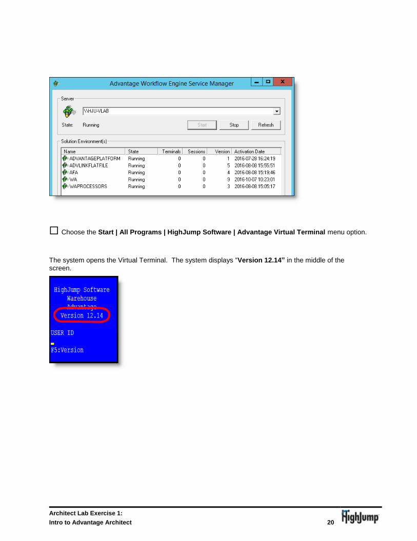
Choose the Start | All Programs | HighJump Software | Advantage Workflow Engine Service
Manager menu option.
The system displays the engine icon in the system tray. A red icon indicates that the Advantage
Workflow Engine is not running.
Double-click the engine icon in the system tray.
The system opens the Advantage Workflow Engine Service Manager window.
Click the Start button on the top portion of the window.
When the engine icon in the top portion of the screen is green, and all of the solution environment icons are green, then the HighJump system is fully running. At this point, the Virtual Terminal will work correctly.
Architect Lab Exercise 1:
Intro to Advantage Architect 20
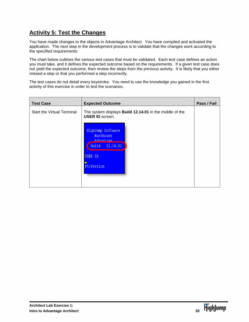
Choose the Start | All Programs | HighJump Software | Advantage Virtual Terminal menu option.
The system opens the Virtual Terminal. The system displays “Version 12.14” in the middle of the screen.

Architect Lab Exercise 1:
Intro to Advantage Architect 21
Activity 2: Understand the Requirements
This activity identifies the changes that will be made to the USER ID screen of the Logon process.
The existing version information (“Version 12.0”) that appears on the USER ID screen refers to the version number of the application delivered by the HighJump product development team. This is a good starting point for determining exactly which application is running on the terminals. However, it does not give the full picture. A better option is to include the version number and a build number on the USER ID screen. By using the build number, an administrator can track it back to an exact application that was introduced into the environment. This can be especially useful when troubleshooting application issues.
After experimenting with several options, you decide that you want the text to read something similar to “Build 12.10.1” where 12.10 is the version delivered by product development and .1 is the build number delivered by your internal development team. The screenshot below shows the desired solution.
Note: The build number refers to a series of objects which were moved into a given environment at the same time

Architect Lab Exercise 1:
Intro to Advantage Architect 22
Activity 3: Develop the Changes
In the previous activities you reviewed how the system currently handles the initial dialog on the RF terminal and you understood the warehouse manager’s desires. Now you will make the changes to the business logic in order to meet the requirements dictated by the warehouse manager. However, before you can make the changes, you must first open the development tool. The procedures below demonstrate how to open the Advantage Architect tool.
Choose the Start | All Programs | HighJump Software | Advantage Architect menu option.
The system opens the Connect to Application Repository window. A repository is a SQL Server / Oracle database that houses all of the Advantage Architect objects for the Advantage Architect applications. In this window you instruct the system where the repository is located.
Enter (local) in the Server Name edit box.
Enter REPOS in the Database Name edit box.
Select the Use SQL Server Authentication radio button.
Open the Training folder on the desktop.
Open the Misc folder.
Double-click the login.txt file.
Use the Architect section of the login.txt file to populate the Login and Password edit boxes of the Connection dialog.
Click the Connect button.
The system displays the Application Login window.

Architect Lab Exercise 1:
Intro to Advantage Architect 23
Type your name in the User Name edit box. (There is no validation on this entry.)
Click the OK button.
The system opens the Advantage Architect tool.
Similar to other software programs, Advantage Architect allows you to interact with multiple applications and the same time. WA (Warehouse Advantage) is the name of the application that contains the business rules for managing inventory inside the four walls of the warehouse. The vast majority of the exercises in this manual utilize the WA application. The procedures below demonstrate how to indicate that you want to work with the application called WA.
Click the Repository tab near the lower left corner of the window.
The system displays a list of all of the applications contained within the repository. In the training instance, there are four different applications.

Architect Lab Exercise 1:
Intro to Advantage Architect 24
Double-click the WA node.
At this point, the system makes WA the active application in Architect; it changes the title of the middle tab (in the lower left corner) to WA; it brings focus to the middle tab which displays a list of objects currently defined in the WA application; and it displays WA in the top drop down list;
In the steps above, you established a connection with the repository and you pointed to a specific application. The next step in the development process is to modify the Advantage Architect objects which control the “HighJump Software” text on initial RF terminal screen. In this exercise and the ones that follow, the manual simply indicates which object you need to change. However, as you learn how to read process objects and as you learn how to use Visual Debugger (which is taught in a later exercise), you will be able to more easily identify which objects needs to change on your own. The chart below outlines all of the objects that you will create or modify in this exercise. The Base App Object column indicates whether the object exists in the WA base application.
Type Name Base App Object
Purpose
Resource SCREEN Version Yes The value of the resource is displayed in the middle of the USER ID screen. The base value is set to “Version”.
Field SYS_VERSION Yes The value of this field is displayed in the middle of the USER ID screen. The base value is a constant set to “12.14”

Architect Lab Exercise 1:
Intro to Advantage Architect 25
The following procedures demonstrate how to modify the Advantage Architect objects in order to change the text on the initial RF terminal screen from “Version 12.14” to “Build 12.14.1”.
Object Name: SCREEN Version Type: Resource Base Application Object: Yes Purpose: This resource is displayed in the middle of the USER ID screen. The current value is “Version”.
Choose the Define | Resource menu.
Right-click the SCREEN Version node.
Choose the View Definition menu.
Choose the Version Control | Check Out menu.
The system displays the object in edit mode.
Enter Build in the Text edit box.
Choose the File | Save menu.
The finished object looks like the following screenshot.

Architect Lab Exercise 1:
Intro to Advantage Architect 26
Object Name: SYS_VERSION Type: Field Base Application Object: Yes Purpose: The value of this field is displayed in the middle of the USER ID screen. The field is defined as a constant with a value of “12.14”.
Choose the Define | Field menu.
Right-click the SYS_VERSION node.
Choose the View Definition menu.
Choose the Version Control | Check Out menu.
The system displays the object in edit mode.
Type 12.14.01 in the Field Value edit box.
Choose the File | Save menu.
The finished object looks like the following screenshot.

Architect Lab Exercise 1:
Intro to Advantage Architect 27
Activity 4: Compile and Activate the Changes
In the activity above you modified all of the necessary objects in Advantage Architect in order to change the text on the initial screen of the RF terminal. However, if you view the Virtual Terminal, you will see that the changes have had no impact. In order to see the changes on the Virtual Terminal, you must first compile the application and then activate the application (to the Virtual Terminals).
The compile component looks for syntax errors in the application. If it finds no syntax errors, then it creates a single file on the hard drive which contains all of the business rules for the given application. The activation component makes this modified application available to all of the RF terminals. The next several procedures demonstrate how to compile and activate the WA application.
Choose the Run | Compile Application menu.
The system displays the Compile Application dialog.
Choose WA in the Application drop-down box.
The system automatically populates the Compilation Folder edit box. There is no need to change it.
Select the Development Compile radio button.
Click the Compile button.
The system displays several informational messages related to the compile in the Output Window.

Architect Lab Exercise 1:
Intro to Advantage Architect 28
It also displays a progression bar in lower left corner of the tool to indicate that the compile is in progress.
When the compile is complete the system displays a dialog indicating that it was successful along with the number of warnings that it found. In this case, the warnings are because some of the modules (Labor Advantage, Yard Advantage) have not been installed in the training environment. These warnings will not cause any problems with the Warehouse Advantage application.
At this point the system gives you an option for activating the application.
Click the Yes button.
The system displays the Activate Application dialog.

Architect Lab Exercise 1:
Intro to Advantage Architect 29
The Compilation Folder edit box points to the folder which contains the output from the compile. The system defaults this value correctly. There is no need to change it.
The Solution Name setting indicates the solution environment (see the AWESM tool) to which the Architect application will be activated.
Choose WA in the Solution Name drop down box.
Choose the Stop and Restart radio button.
Check the Continue on Warning checkbox.
Click the OK button.
Behind the scenes, the system shuts down the WA solution environment. It activates the WA application. Then it restarts the WA solution environment. When everything is done, the system displays a confirmation window.
Click the OK button.
Architect Lab Exercise 1:
Intro to Advantage Architect 30
Activity 5: Test the Changes
You have made changes to the objects in Advantage Architect. You have compiled and activated the application. The next step in the development process is to validate that the changes work according to the specified requirements.
The chart below outlines the various test cases that must be validated. Each test case defines an action you must take, and it defines the expected outcome based on the requirements. If a given test case does not yield the expected outcome, then review the steps from the previous activity. It is likely that you either missed a step or that you performed a step incorrectly.
The test cases do not detail every keystroke. You need to use the knowledge you gained in the first activity of this exercise in order to test the scenarios.
Test Case Expected Outcome Pass / Fail
Start the Virtual Terminal The system displays Build 12.14.01 in the middle of the USER ID screen.

Architect Lab Exercise 1:
Intro to Advantage Architect 31
Activity 6: Check in the Objects
Earlier in this exercise, you checked out several objects and made changes to them. As long as you have the objects checked out, you are the only developer who can alter its definition. Because your changes met the requirements, you can now check the objects back into the repository which makes them available to other Advantage Architect developers. The procedures below demonstrate how to check the objects back into the repository.
Choose the Version Control | Pending Checkins menu.
The system displays a list of all objects that you have checked out.
It gives you the opportunity to select exactly which objects you want to check into the repository. You can select all objects or a subset of the objects.
Select the checkbox to the left of the WA node.
The system automatically marks all objects for check in.
The Pending Checkins window does not contain any drop down menus. Most of the time you will utilize one of the buttons on the Pending Checkins button bar to perform some activity.

Architect Lab Exercise 1:
Intro to Advantage Architect 32
Click the Checkin button (2nd button from the left) in the Pending Checkins window button bar.
The system displays the Version Control Comments window.
This window allows you to write some comments related to your changes which the system associates with all of the selected objects. These comments are optional, but highly recommended. Later in the class you will see how these comments can be beneficial for understanding the history of what has changed in the application.
Type Lab Exercise 1 in the Version Control Comments edit box.
Click the Continue button.
The system checks in all of the selected objects, and makes them available to other developers. And it clears the Pending Checkins window. You are now done these objects, so you can close them.
Choose the View | Close All menu option.
By checking in the objects, you have completed the development cycle for this exercise. In review, you walked through the following activities in this exercise.
1. Understand the Current Process 2. Understand the Requirements 3. Modify the Business Logic 4. Compile and Activate the Changes 5. Test the Changes 6. Check in the Objects
These six activities provide a solid basis for any Architect development that you will do in the future. The remaining exercises in the manual also follow this model.

Architect Lab Exercise 2:
Call an Existing Process Object 33
Architect Lab Exercise 2: Call an Existing Process Object
Introduction
In this exercise you will display a Transaction Complete dialog to the user when he finishes one iteration of the Physical business process.
Background Information Before a warehouse goes live with the HighJump system, a warehouse will often suspend all operations in order to perform a physical. This means that they will count all inventory in all locations in the warehouse. This inventory then becomes the master inventory for the start of the go-live event. Sometimes warehouses will also perform an annual physical after the HighJump system has been live.
The Physical Inventory business process in Warehouse Advantage is the process that is used to count the inventory during a physical. This exercise uses the Physical Inventory business process as a basis for all activities. By default, the Physical Inventory business process will not direct the user to a specific location. Instead, it relies upon the warehouse manager to devise a plan in which the counters visit all locations in the warehouse.

Architect Lab Exercise 2:
Call an Existing Process Object 34
Activity 1: Understand the Current Process
This activity demonstrates how the Physical Inventory process operates in the Warehouse Advantage base application.
In the Virtual Terminal, enter AMY on USER ID dialog.
Enter AMY on the PASSWORD dialog.
Enter FAAMY on the as EQUIPMENT / ZONE dialog.
Press the F8 key to scroll to the next page.
Enter option 7 (the Inv Control menu.)
Enter option 2 (the Cycle Counts menu.)
Enter option 3 (the Physical menu.)
Enter P101 at the Location dialog.
Enter Y at the Clear Location dialog.
Enter NNFG00000 at the Item ID dialog.
Enter 1 at the Pallets of 100 dialog.
Enter 2 at the Cases of 10 dialog.
Enter 3 at the Eaches dialog.
At this point you have counted a total of 123 units (1 pallet of 100 + 2 cases of 10 + 3 eaches) of NNFG00000 in the P101 location. The system takes this information; updates the inventory tables; and then loops back to the top of the business process. However, the system gives no visual indication that it successfully completed one cycle of the process.
Press the F1 key to return to the main menu.

Architect Lab Exercise 2:
Call an Existing Process Object 35
Activity 2: Understand the Requirements
This activity identifies the changes that the warehouse manager wants to make to the Physical Inventory process.
The warehouse manager calls you on the phone. He explains that some users are confused about the automatic looping feature of the Physical Inventory process. The users don’t receive any visual indication that the transaction was successful. As a result, there is a degree of uncertainly in their minds as to whether or not the system accepted the count. The warehouse manager acknowledges that the problem could be resolved with some minimal training. However, he would prefer a visual acknowledgement at the end of each loop which indicates a successful transaction.
The two of you work together on a design, and you agree that the Physical Inventory process should display a Transaction Complete dialog at the end of each loop. The dialog forces the user to acknowledge the message before continuing with the next location / item. You agree that the dialog should look like the following diagram.
Activity 3: Develop the Changes
The procedures below demonstrate how to modify the Physical Inventory business process in order to meet the requirements dictated by the warehouse manager. The chart that follows outlines all objects that you will create or modify in this activity.
Type Name Base App Object
Purpose
Business Process Object
Physical Yes Top-level business process object which drives all rules for the Physical Inventory process.
Architect Lab Exercise 2:
Call an Existing Process Object 36
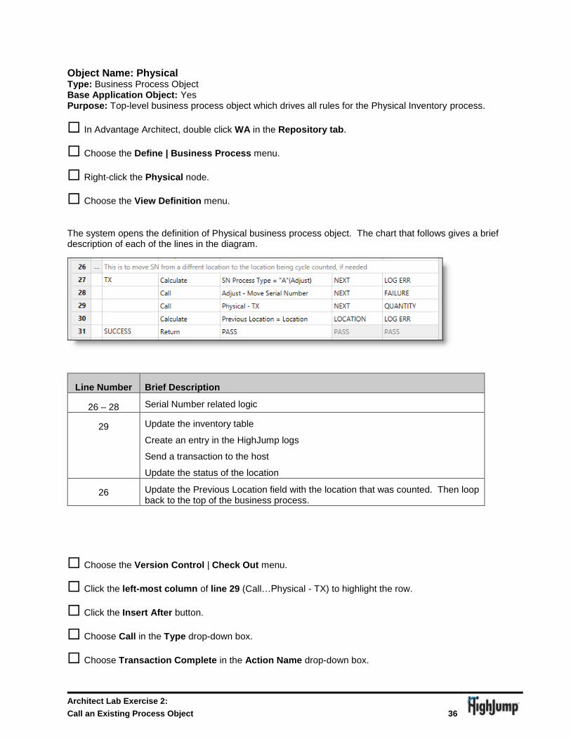
Object Name: Physical Type: Business Process Object Base Application Object: Yes Purpose: Top-level business process object which drives all rules for the Physical Inventory process.
In Advantage Architect, double click WA in the Repository tab.
Choose the Define | Business Process menu.
Right-click the Physical node.
Choose the View Definition menu. The system opens the definition of Physical business process object. The chart that follows gives a brief description of each of the lines in the diagram.
Line Number Brief Description
26 – 28 Serial Number related logic
29 Update the inventory table
Create an entry in the HighJump logs
Send a transaction to the host
Update the status of the location
26 Update the Previous Location field with the location that was counted. Then loop back to the top of the business process.
Choose the Version Control | Check Out menu.
Click the left-most column of line 29 (Call…Physical - TX) to highlight the row.
Click the Insert After button.
Choose Call in the Type drop-down box.
Choose Transaction Complete in the Action Name drop-down box.

Architect Lab Exercise 2:
Call an Existing Process Object 37
Choose the File | Save menu.
The finished process object looks like the following screenshot.
Line Number Description
26 – 28 Serial Number related logic
29 Update the inventory table
Create an entry in the HighJump logs
Send a transaction to the host
Update the status of the location
30 Display the Transaction Complete dialog
31 Update the Previous Location field with the location that was counted. Then loop back to the top of the business process.
Activity 4: Compile and Activate the Changes
At this point you have modified several objects to meet the requirements dictated by the warehouse manager. However, if you view the Virtual Terminal, you will see that the changes have had no impact. In order to see the changes reflected on the Virtual Terminal, you must first compile the application and then activate the application.
Compile the application
Activate the application

Architect Lab Exercise 2:
Call an Existing Process Object 38
Activity 5: Test the Changes
The chart below outlines the various test cases that must be validated. Each test case defines an action you must take, and it defines the expected outcome based on the requirements. If a given test case does not yield the expected outcome, then review the steps from the previous activity. It is likely that you either missed a step or performed a step incorrectly. The test cases do not detail every keystroke. You need to use the knowledge you gained in the first activity of this exercise in order to test the scenarios.
Starting the Physical Business Process
From the Main Menu choose F8, Option 7, Option 2, Option 3
Enter P101 at the Location dialog.
Enter Y at the Clear Location dialog.
Enter NNFG00000 at the Item ID dialog.
Test Case Expected Outcome Pass / Fail
Enter 1, 2, and 3 at the Pallets, Cases, and Eaches dialogs respectively.
The system displays the Transaction Complete dialog.
Activity 6: Check in the Objects
Earlier in this exercise, you checked out several objects and made changes to them. As long as the objects are checked out in your name, you are the only developer who can alter their definitions. Because your changes met the warehouse manager’s requirements, you can make the objects available to other Architect developers in your company. In the steps below, you will check in the objects so that other developers can make additional changes to them.

Architect Lab Exercise 2:
Call an Existing Process Object 39
Choose the Version Control | Pending Checkins menu.
Check in all of the objects.
Close all of the tabs.

Architect Lab Exercise 3:
Compare Actions 40
Architect Lab Exercise 3: Compare Actions
Introduction
In this exercise you will add validation to a Quantity dialog in the Unload Inbound Order business process.
Background Information This exercise uses the Unload Inbound Order business process as a basis for all activities. The Unload Inbound Order business process records the arrival of an inbound order into the warehouse. However, this process does not receive any inventory into the warehouse. It only indicates that an inbound order has appeared at an inbound door. Additionally, this process generates a Directed Receipt task which another user could utilize to begin the actual receiving activities.
This exercise emphasizes the concept of a compare action. The following online lesson introduces compare actions.
1. Open the Advantage Architect online course.
2. Review the Create Compare Action topic.

Architect Lab Exercise 3:
Compare Actions 41
Activity 1: Understand the Current Process
This activity demonstrates how the Unload Inbound Order process operates in the Warehouse Advantage base application.
Log in to the Virtual Terminal as AMY / AMY / FAAMY.
Enter option 1 (the Receipts menu.)
Enter option 1 (the Unload Inbd Order menu.)
Enter PO1 at the PO Number dialog.
Press the Enter Key at the Carrier Name dialog.
Enter any number displayed on the list at the Carrier Name List dialog.
Enter S1 at the Location dialog.
Enter 90000 at the Quantity dialog.
Note that the system accepted the outrageously large number.
If the system bypasses the Quantity prompt then retry the process with a different Purchase Order number. PO1, PO2, PO3, PO4, and PO5 are all valid purchase orders. If the system still bypasses the Quantity prompt, then open SQL Server Management Studio and run the reset_pos.sql script in the TRAINING \ ARCHITECT \ SQL folder on the desktop. If you have any difficulties, then please contact an instructor.
Press the Enter key at the Transaction Complete dialog.
Press the F1 key to return to the menu.

Architect Lab Exercise 3:
Compare Actions 42
Activity 2: Understand the Requirements
This activity identifies the changes that the warehouse manager wants to make to the Unload Inbound Order process.
The warehouse manager calls you on the phone. He explains that several users are mistyping the quantity value in the Unload Inbound Order process. The end result is that Warehouse Advantage passes outrageously large numbers to the host system, and the host system is not able to process the transactions. Consequently, an administrator must intervene in order to correct the errors. The warehouse manager would like to prevent this from happening.
The two of you work together on a design, and you agree that the Unload Inbound Order process should include some level of validation on the quantity. You agree that the system should not allow quantity values greater than 200.
Activity 3: Develop the Changes
As with any requirement, there is always more than one solution. In this case, the best solution would be to place the value of 200 into a database table and then compare the database value with the user-entered value. This allows the warehouse manager to easily change the value from 200 to another value without needing a modification to the application. You will learn that approach in a later exercise. However, in order to simplify the development process and the learning process, this exercise solves the requirement by using a constant value embedded in the application. The solution below is not the best solution for this specific requirement, but the skills you learn in this exercise can be applied in a multitude of other situations.
In this activity you will create a new process object that contains the quantity verification rules. Then you will insert this process object into the Unload Inbound Order logic. The diagrams below show the final process object that contains the quantity verification rules as well as a brief description of its content.
Line Number Description
1 – 2 “Is the user–entered Quantity field less than or equal to 200?” If YES, then exit the process object with a PASS condition. If NO, then advance to line 3.

Architect Lab Exercise 3:
Compare Actions 43
3 – 4 Build an error message. Then exit the process object with a FAIL condition.
The procedures below demonstrate how to create a process object shell that will eventually contains the verification rules.
Double click WA in the Repository tab.
Choose the Define | Process Object menu option.
Choose the File | New menu option.
Enter Verify Quantity <= 200 in the Name edit box.
Click the Properties button to collapse the header information.
At this point, you have a basic process object to which you can add additional objects and actions.
The procedures below demonstrate how to create the compare action which compares the user-entered quantity against a constant value of 200. The procedures demonstrate how to perform this task from within the process object grid.
Click the left-most column of Line 1 (Return…PASS) to highlight the line.
Click the Insert Before button.
Choose Compare in the Type drop down box.
Click the Action Name edit box to bring focus to that cell.
Click the Asterisk button on the right side of the Action Name drop down box.
Chose the Compare Action menu option.
Enter Quantity <= 200? In the Action Name edit box.

Architect Lab Exercise 3:
Compare Actions 44
Click the Checkmark button on the right side of the Action Name drop down box.
After you click the checkmark button, the system creates a new compare action with the given name. Additionally, the system creates a new tab for the new compare action along the top of the tool.
Click the Quantity <= 200? tab (compare action) along the top of the tool.
Choose Quantity in the Field 1 drop down box.
Choose <= (less than or equals) in the Operator drop down box.
Click the Asterisk button to the right of the Field 2 / Constant drop down box.
Choose the Constant – Numeric menu option.
Type 200 in the Field 2 / Constant drop down box.
Choose the File | Save menu option.
The resulting compare action looks like the following diagram.
The procedures below demonstrate how to modify the verification process object so that it builds an error message when the quantity is greater than 200. The Warehouse Advantage base application contains a

Architect Lab Exercise 3:
Compare Actions 45
calculate action which already builds an appropriate error message. The verification process object simply references the existing logic.
Click the Verify Quantity <= 200 tab (process object) along the top of the tool.
Click the left-most column of Line 2 (Return…PASS) to highlight the line.
Click the Insert After button.
Enter TOO_BIG in the Label edit box.
Choose Calculate in the Type drop down box.
Choose Err: Quantity Too Great in the Action Name drop down box.
Choose TOO_BIG in the Fail drop down box of line 1 (Compare…Quantity <= 200?)
Choose the File | Save menu option. The finished process object looks like the following diagram.
At this point the verification process object is complete. However, in order for the solution to meet the requirements, this process object must be inserted somewhere in the Unload Inbound Order business process. The procedures below demonstrate how to call this verification logic from within the Unload Inbound Order business process.
Choose the View | Close All menu option.
Choose the Define | Business Process menu option.
Double click the Unload Inbound Order node. The system opens the current definition of the process object. This process object is the top-level object which contains all rules for the Unload Inbound Order business logic. The key is to find the logic in this process which prompts for a quantity. Naming conventions will be discussed later in this class. However, even without knowing naming conventions, you could probably guess that line 8 of this process object is

Architect Lab Exercise 3:
Compare Actions 46
somehow related to capturing a quantity from the end user. The Label edit box (QUANTITY) and the Action Name drop down box (Unload Order – Quantity) of line 8 are good indicators of the nature of the underlying logic.
Click the Action Name column of line 8 (Call…Unload Order – Quantity) to bring focus.
Double click the Action Name column of line 8 (Call…Unload Order – Quantity).
The system opens the definition of the process object. This process object contains all of the logic in the Unload Inbound Order business process that relates to capturing a quantity from the end user and then validating it. The diagrams below show the current definition of the process object and a brief description of its content.
Line Number Description
4 Populates a field which dictates the behavior of the quantity dialog.
5 Populates the fields which will eventually be displayed to the end user on the quantity dialog.
6 Calls a generic process object that displays a quantity dialog to the end user based upon the fields set in line 4 and line 5.

Architect Lab Exercise 3:
Compare Actions 47
Since the logic in line 6 (Call…Universal Quantity) displays the quantity dialog to the end user, the natural place for additional verification on the quantity value is immediately after line 6. The procedures below demonstrate how to add the new verification logic to this process object.
Choose the Version Control | Check Out menu.
Click the left-most column of Line 6 (Call…Universal Quantity) to highlight the line.
Click the Insert After button.
Choose Call in the Type drop down box.
Choose Verify Quantity <= 200 in the Action Name drop down box.
Choose SCR TEXT in the Fail drop down box.
Choose the File | Save menu option.
The diagram below shows the resulting process object. A brief summary follows.
Now, immediately after the system captures the quantity from the user, the system executes the verification logic. If the entered quantity is less than or equal to 200, the system exits the process object with a PASS condition. Otherwise, it presents the quantity dialog again.

Architect Lab Exercise 3:
Compare Actions 48
Activity 4: Compile and Activate the Changes
At this point you have modified several objects to meet the requirements dictated by the warehouse manager. However, if you view the Virtual Terminal, you will see that the changes have had no impact. In order to see the changes reflected on the Virtual Terminal, you must first compile the application and then activate the application.
Compile the application
Activate the application

Architect Lab Exercise 3:
Compare Actions 49
Activity 5: Test the Changes
The chart below reviews the business process, and it outlines the various test cases that must be validated. Each test case defines an action you must take, and it defines the expected outcome based on the requirements. If a given test case does not yield the expected outcome, then review the steps from the previous activity. It is likely that you either missed a step or performed a step incorrectly. The test cases do not detail every keystroke. You need to use the knowledge you gained in the first activity of this exercise in order to test the scenarios.
Starting the Unload Inbound Order Business Process
From the Main Menu choose Option 1, Option 1
Enter PO2 at the PO Number dialog.
Press the Enter Key at the Carrier Name dialog.
Enter any number displayed on the list at the Carrier Name List dialog.
Enter S2 at the Location dialog.
The system should display the Quantity screen. If the system does not disply the Quantity prompt then retry the process with a different Purchase Order number. PO1, PO2, PO3, PO4, and PO5 are all valid purchase orders. If the system still bypasses the Quantity prompt, then open SQL Server Management Studio and run the reset_pos.sql script in the TRAINING \ ARCHITECT \ SQL folder on the desktop. If you have any difficulties, then please contact an instructor.
Test Case Expected Outcome Pass / Fail
Enter 201 at the Quantity dialog.
System displays QUANTITY TOO GREAT error and remains on the Quantity dialog.
Enter 200 at the Quantity dialog.
System continues with the Transaction Complete dialog.

Architect Lab Exercise 3:
Compare Actions 50
Activity 6: Check in the Objects
Earlier in this exercise, you checked out several objects and made changes to them. As long as the objects are checked out in your name, you are the only developer who can alter their definitions. Because your changes met the warehouse manager’s requirements, you can make the objects available to other Architect developers in your company. In the steps below, you will check in the objects so that other developers can make additional changes to them.
Choose the Version Control | Pending Checkins menu.
Check in all of the objects.
Close all of the tabs.

Architect Lab Exercise 4:
Calculate Actions 51
Architect Lab Exercise 4: Calculate Actions
Introduction
In this exercise you will validate that all container numbers in the Reusable Container Receipt process begin with the same prefix characters. Additionally, you will allow an administrator to change the prefix characters on demand.
Background Information This exercise uses the Reusable Container Receipt business process as a basis for all of the activities. A container (in the context of the Reusable Container business processes) is a sturdy structure used to ship goods from a warehouse to a customer. The automotive industry often uses large, metal totes when moving inventory from a distribution center to a store. The brewery industry often uses industrial pallets to move large kegs of beer from a brewery to a store. In each of these cases, the metal totes and the industrial pallets serve as a container (in the context of the Reusable Container business processes.) After the customer has removed the inventory from the container, they send the empty containers back to the warehouse. The warehouse can then reuse the containers for additional deliveries.
Because of their reusable nature, it is beneficial to track when a container leaves the warehouse and when a container is returned to a warehouse. If a customer does not return a container, the warehouse could potentially charge the customer. The Reusable Container Shipping business process records when a container leaves the warehouse. The Reusable Container Receipt business process, which is the focus of this this exercise, records when an empty container is returned to the warehouse.
This exercise emphasizes the concept of calculate actions. It also utilizes fields and resources for the first time. The following online lessons give an introduction to these three concepts.
1. Open the Advantage Architect online course.
2. Review the Create a Text Field topic.
3. Review the Create a Number Field topic.
4. Review the Create a Date and Time Field topic.
5. Review the Create Calculate Action topic.
6. Review the Create Resource topic.

Architect Lab Exercise 4:
Calculate Actions 52
Activity 1: Understand the Current Process
This activity demonstrates how the Reusable Container Receipt process operates in the Warehouse Advantage base application.
Log in to the Virtual Terminal as AMY / AMY / FAAMY.
Enter option 1 (the Receipts menu.)
Press the F8 key to scroll down a page.
Enter option 8 (the Container Receipt menu.)
Enter ABCDEF at the Container Number dialog.
Note that the system accepts this somewhat unconventional container number and then advances to the next screen in the business process.
Press the F1 key to navigate back to the Container Number dialog.
Press the F1 key to return to the menu.

Architect Lab Exercise 4:
Calculate Actions 53
Activity 2: Understand the Requirements
This activity identifies the changes that the warehouse manager wants to make to the Reusable Container Receipt business process.
The warehouse manager calls you on the phone. He explains that several users are incorrectly scanning item number barcodes at the container number dialog of the Reusable Container Receipt business process. Because there is no validation on this dialog, the system accepts these values, and sends the incorrect information to the host. Consequently, an administrator must intervene in order to correct the errors. The warehouse manager would like to prevent this from happening.
The two of you agree that the best solution would be to validate the user-entered container number against a database table that contains a listing of all containers. However, after investigating that option, you learn that there are some limitations on the host side which prevent you from getting a complete list of containers in a reasonable time frame.
As a compromise with those limitations, you and the warehouse manager agree on another solution. All container numbers currently in the warehouse begin with “CN”. You agree to validate that the first two characters of the user-entered container number are “CN”. The warehouse manager also mentions that they will be renaming the container numbers in the next couple months. You agree that the solution will allow the warehouse manager to easily change the “CN” validation to a different (two-character) value on his own whenever the renaming takes place.
Activity 3: Develop the Changes
In this activity you will create a new process object that compares the first two-characters of the user-entered container number against a value stored in a database table. Then you will insert this process object into the Reusable Container Receipt logic. The diagrams below show the final process object that contains the comparison logic as well as a brief description of its content.
Line Number Description
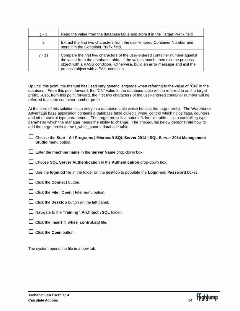
Architect Lab Exercise 4:
Calculate Actions 54
1 - 3 Read the value from the database table and store it in the Target Prefix field
5 Extract the first two characters from the user-entered Container Number and store it in the Container Prefix field.
7 - 11 Compare the first two characters of the user-entered container number against the value from the database table. If the values match, then exit the process object with a PASS condition. Otherwise, build an error message and exit the process object with a FAIL condition.
Up until this point, the manual has used very generic language when referring to the value of “CN” in the database. From this point forward, the “CN” value in the database table will be referred to as the target prefix. Also, from this point forward, the first two characters of the user-entered container number will be referred to as the container number prefix. At the core of this solution is an entry in a database table which houses the target prefix. The Warehouse Advantage base application contains a database table called t_whse_control which holds flags, counters, and other control-type parameters. The target prefix is a natural fit for this table. It is a controlling-type parameter which the manager needs the ability to change. The procedures below demonstrate how to add the target prefix to the t_whse_control database table.
Choose the Start | All Programs | Microsoft SQL Server 2014 | SQL Server 2014 Management Studio menu option.
Enter the machine name in the Server Name drop-down box.
Choose SQL Server Authentication in the Authentication drop-down box.
Use the login.txt file in the folder on the desktop to populate the Login and Password boxes.
Click the Connect button.
Click the File | Open | File menu option.
Click the Desktop button on the left panel.
Navigate to the Training \ Architect \ SQL folder.
Click the insert_t_whse_control.sql file.
Click the Open button.
The system opens the file in a new tab.

Architect Lab Exercise 4:
Calculate Actions 55
Choose the Query | Execute menu option.
The system inserts a row into the t_whse_control table for the target prefix. Then it displays the row that it inserted. The control_type column holds the text “TARGET_CONT_PREFIX”. And the c1 column holds the text “CN”. These two columns will be important as you build the process object.
Choose the File | Exit menu option.
The procedures below demonstrate how to create a process object shell that will eventually contain the verification rules for the user-entered container number.
In Advantage Architect, double click WA in the Repository tab.
Choose the Define | Process Object menu option.
Choose the File | New menu option.
Enter Verify Container Number Prefix in the Name edit box.
Click the Properties button to collapse the header information.
Choose the File | Save menu option.

Architect Lab Exercise 4:
Calculate Actions 56
At this point, you have a basic process object from which you can create additional objects and actions.
In the next several steps you will create the first three lines of the process object which handles the prefix verification rules. The diagrams show the completed process object and a detailed explanation of each of the first three lines.
Line Number Description
1 Updates the Control Type field to the text “TARGET_CONT_PREFIX”. This text directly corresponds with the control_type column of the t_whse_control table for the row that you inserted.
2 Reads a row out of the t_whse_control database table using the Control Type field. After the system finds the row in the database, it populates several fields. It populates the WHC Unused c1 field with the value from the c1 column of the t_whse_control database table. In this specific instance, the system updates the WHC Unused c1 field to “CN”. DB Read Whse Control is a process object in the Warehouse Advantage base application.
3 Sets the Target Prefix field equal to the value of the WHC Unused c1 field. In this specific instance, the system updates the Target Prefix field to “CN”.

Architect Lab Exercise 4:
Calculate Actions 57
The procedures below demonstrate how to create each of the individual actions and insert them into the prefix verification process object. In some cases, there are objects in the Warehouse Advantage base application that are similar to the needed functionality. In those situations, the procedures direct you to create a copy of the base object and then modify it accordingly. When there is no similar object in the Warehouse Advantage base application, the procedures direct you to create a new object with a blank template.
Choose the Define | Calculate menu option.
Right click the Control Type = AFA_INSTALLED node.
Choose the Copy As menu option.
The system displays the Copy As window.
Type Control Type = TARGET_CONT_PREFIX in the New Object Name edit box.
Click the OK button.
The system displays the new calculate action which is a copy of the Control Type = AFA_INSTALLED.
Type TARGET_CONT_PREFIX in the Operand 1 edit box.
Choose the File | Save menu option.
The diagram below shows the finished calculate action.

Architect Lab Exercise 4:
Calculate Actions 58
Right click the Verify Container Number Prefix tab (process object) along the top of the tool.
Choose the Close All But This menu option.
Click the left-most column of Line 1 (Return…PASS) to highlight the line.
Click the Insert Before button.
Choose Calculate in the Type drop down box.
Choose Control Type = TARGET_CONT_PREFIX in the Action Name drop down box.
The diagram below shows the resulting process object.
Click the Insert After button.
Choose Call in the Type drop down box.
Choose DB Read Whse Control in the Action Name drop down box.
The diagram below shows the resulting process object.

Architect Lab Exercise 4:
Calculate Actions 59
Click the Insert After button.
Choose Calculate in the Type drop down box.
Click the Action Name edit box to bring focus to that cell.
Click the Asterisk button on the right side of the Action Name drop down box.
Chose the Calculate Action menu option.
Enter Target Prefix = WHC c1 in the Action Name edit box.
Click the Checkmark button on the right side of the Action Name drop down box.
After you click the checkmark button, the system creates a new calculate action with the given name. Additionally, the system creates a new tab for the new calculate action along the top of the tool.
Choose the File | Save menu option
The diagram below shows the resulting process object.

Architect Lab Exercise 4:
Calculate Actions 60
Click the Target Prefix = WHC c1 tab (calculate action) along the top of the tool.
Click the Insert After button.
Choose Equals in the Operation selection box.
Click the Result cell to bring focus to it.
Click the Asterisk button on the right side of the Result drop down box.
Select the Field - String menu option if it is not already selected.
Enter Target Prefix in the Result edit box.
Click the Checkmark button on the right side of the Result edit box.
After you click the checkmark button, the system creates a new field with the given name. Additionally, the system creates a new tab for the new field along the top of the tool.
Choose WHC Unused c1 in the Operand 1 drop down box.
Choose the File | Save menu option.
The diagram below shows the resulting calculate action.

Architect Lab Exercise 4:
Calculate Actions 61
Click the Target Prefix tab (field) along the top of the tool.
Enter 30 in the Length edit box.
Choose the File | Save menu option.
The diagram below shows the resulting field
.
In the next several steps you will create lines 4 – 6 of the process object which handles the prefix verification rules. The diagrams show the completed process object and a detailed explanation of lines 4 – 6.

Architect Lab Exercise 4:
Calculate Actions 62
Line Number Description
4 A comment.
5 Populate the Container Prefix field with the first two characters of the Container Number field. The system populated the Container Number field with the value entered by the user at the dialog earlier in the business process.
6 A comment
The procedures below demonstrate how to create each of the individual actions and insert them into the prefix verification process object.
Right click the Verify Container Number Prefix tab (process object) along the top of the tool.
Choose the Close All But This menu option.
Right click the left-most column of Line 4 (Return…PASS) to highlight the line.
Choose the Ins Comment Before menu option.
The diagram below shows the resulting process object.

Architect Lab Exercise 4:
Calculate Actions 63
Click the Insert After button.
Choose Calculate in the Type drop down box.
Click the Action Name edit box to bring focus to that cell.
Click the Asterisk button on the right side of the Action Name drop down box.
Chose the Calculate Action menu option.
Enter Container Prefix = Mid (Cont Num) in the Action Name edit box.
Click the Checkmark button on the right side of the Action Name drop down box.
After you click the checkmark button, the system creates a new calculate action with the given name. Additionally, the system creates a new tab for the new calculate action along the top of the tool.
Choose the File | Save menu option
The diagram below shows the resulting process object.

Architect Lab Exercise 4:
Calculate Actions 64
Click the Container Prefix = Mid (Cont Num) tab (calculate action) along the top of the tool.
Click the Insert After button.
Choose Mid String in the Operation selection box.
Click the Result cell to bring focus to it.
Click the Asterisk button on the right side of the Result drop down box.
Select the Field - String menu option if it is not already selected.
Enter Container Prefix in the Result edit box.
Click the Checkmark button on the right side of the Result edit box.
After you click the checkmark button, the system creates a new field with the given name. Additionally, the system creates a new tab for the new field along the top of the tool.
Choose Container Number in the Operand 1 drop-down box.
Click the Asterisk button to the right of Operand 2.
Choose the Constant – Numeric menu option.
Type 1 in the Operand 2 edit box.
Click the Operand3 cell to bring focus to it.

Architect Lab Exercise 4:
Calculate Actions 65
Click the Asterisk button to the right of Operand 3.
Choose the Constant – Numeric menu option.
Type 2 in the Operand 3 edit box.
Choose the File | Save menu option.
The diagram below shows the resulting calculate action.
Click the Container Prefix tab (field) along the top of the tool.
Enter 30 in the Length edit box.
Choose the File | Save menu option.
The diagram below shows the resulting field.
Right click the Verify Container Number Prefix tab (process object) along the top of the tool.
Choose the Close All But This menu option.
Right click the left-most column of Line 6 (Return…PASS) to highlight the line.

Architect Lab Exercise 4:
Calculate Actions 66
Choose the Ins Comment Before menu option.
Choose the File | Save menu option.
The diagram below shows the resulting process object.
In the next several steps you will create lines 7 - 11 of the process object which handles the prefix verification rules. The diagrams show the completed process object and a detailed explanation of lines 7 – 11.
Line Number Description

Architect Lab Exercise 4:
Calculate Actions 67
7 Ask the question, “Does the Container Prefix field match the Target Prefix field?” If YES, then exit the process object with a PASS condition. If NO, then advance to line 10.
The system populated the Container Prefix field in line 5 and it holds the first 2 characters of the user-entered value. The system populated the Target Prefix field in line 3, and it holds the value from the t_whse_control table.
10 Build an error message. Then exit the process object with a FAIL condition.
The procedures below demonstrate how to create each of the individual actions and insert them into the prefix verification process object.
Click the left-most column of Line 7 (Return…Pass) to highlight the line.
Click the Insert Before button.
Choose Compare in the Type drop down box.
Click the Action Name edit box to bring focus to that cell.
Click the Asterisk button on the right side of the Action Name drop down box.
Chose the Compare Action menu option.
Enter Container Prefix = Target Prefix? in the Action Name edit box.
Click the Checkmark button on the right side of the Action Name drop down box.
After you click the checkmark button, the system creates a new compare action with the given name. Additionally, the system creates a new tab for the new compare action along the top of the tool.
Choose the File | Save menu option
The diagram below shows the resulting process object.

Architect Lab Exercise 4:
Calculate Actions 68
Click the Container Prefix = Target Prefix? tab (compare action) along the top of the tool.
Choose Container Prefix in the Field 1 drop down box.
Choose = (equals) in the Operator drop down box.
Choose Target Prefix in the Field 2 / Constant drop down box.
Choose the File | Save menu.
The diagram below shows the resulting compare action.
Right click the Verify Container Number Prefix tab (process object) along the top of the tool.
Choose the Close All But This menu option.
Right click the left-most column of Line 8 (Return…Pass) to highlight the line.

Architect Lab Exercise 4:
Calculate Actions 69
Choose the Ins Comment Before menu option.
Choose the File | Save menu option.
The diagram below shows the resulting process object.
Choose the Define | Calculate menu option.
Right click the Err: Invalid Item node.
Choose the Copy As menu option.
The system displays the Copy As window.
Type Err: Invalid Prefix in the New Object Name edit box.
Click the OK button.

Architect Lab Exercise 4:
Calculate Actions 70
The system displays the new calculate action which is a copy of Err: Invalid Item.
Click the Operand1 cell to bring focus to it.
Click the Asterisk button on the right side of the Operand 1 drop down box.
Chose the Resource menu option.
Enter Err Invalid Prefix in the Operand 1 edit box.
Click the Checkmark button on the right side of the Operand 1 drop down box.
After you click the checkmark button, the system creates a new resource with the given name. Additionally, the system creates a new tab for the new resource along the top of the tool.
Choose the File | Save menu option.
The diagram below shows the resulting calculate action.

Architect Lab Exercise 4:
Calculate Actions 71
Click the Err Invalid Prefix tab (resource) along the top of the tool.
Enter INVALID PREFIX in the Text edit box.
Choose the File | Save menu option.
The diagram below shows the resulting resource.
Right click the Verify Container Number Prefix tab (process object) along the top of the tool.
Choose the Close All But This menu option.
Click the left-most column of Line 9 (Return…Pass) to highlight the line.
Click the Insert After button.
Enter BAD_PFX in the Label edit box.
Choose Calculate in the Type drop down box.
Choose Err: Invalid Prefix in the Action Name drop down box.
Choose BAD_PFX in the Fail drop down box of line 7 (Compare…Container Prefix = Target Prefix?)
Choose the File | Save menu option.
The diagram below shows the resulting process object.

Architect Lab Exercise 4:
Calculate Actions 72
At this point the prefix verification process object is complete. However, in order for the solution to meet the requirements, this process object must be inserted somewhere in the Reusable Container Receipt business process. The procedures below demonstrate how to call this prefix verification logic from within the Reusable Container Receipt business process.
Choose the View | Close menu option.
Choose the Define | Process Object menu option.
Double click the Reusable Container Receipt node. The system opens the current definition of the process object. This process object is the top-level object which contains all rules for the Reusable Container Receipt business logic. The prefix verification logic is related to the Container Number prompt, so the key is to find the logic in this process which prompts for a container number. Naming conventions will be discussed later in this class. However, even without knowing naming conventions, you could probably guess that line 2 of this process object is somehow related to capturing a container number from the end user. The Label edit box (CONTAINER) and the Action Name drop down box (Container - Container) of line 2 are good indicators of the nature of the underlying logic.

Architect Lab Exercise 4:
Calculate Actions 73
Click the Action Name column of line 2 (Call…Container - Container) to bring focus.
Double click the Action Name column of line 2 (Call…Container - Container).
The system opens the definition of the process object. This process object contains all of the logic in the Reusable Container Receipt business process that relates to capturing a container number from the end user. The diagrams below show the current definition of the process object and a brief description of its content.
Line Number Description
1 Populates several fields which the system displays on the screen when it prompts for a container number.
2 Calls a generic process object that displays a screen to the end user. The system uses the fields populated in line 1 to determine the layout of the screen. If the user entered something other than a function key, then advance to line 4. If the user entered a function key, then advance to line 3.
3 Asks the question, “Did the user press the F1 key?” If YES, then exit the process object with a FAIL condition. If NO, then advance to line 9.
4 Asks the question, “Did the user enter an empty value?” If YES, then advance to line 11. If NO, then advance to line 5.
5 Populate the Container Number field with the value entered by the user.
9 – 11 Each of these 3 lines builds a different error message which the system will eventually present to the end user. Then it advances to line 1.

Architect Lab Exercise 4:
Calculate Actions 74
The logic in line 5 (Calculate…Container Number = Dialog Field) sets the Container Number field equal to the user-entered value, and then it exits the process object with a PASS condition. The natural place for the additional prefix verification on the user-entered value is immediately after line 5. The procedures below demonstrate how to add the new prefix verification logic to this process object.
Choose the Version Control | Check Out menu option.
Click the left-most column of Line 6 (Return…Pass) to highlight the line.
Click the Insert Before button.
Choose Call in the Type drop down box.
Choose Verify Container Number Prefix in the Action Name drop down box.
Choose SCR TEXT in the Fail drop down box.
Choose the File | Save menu option. The diagram below shows the resulting process object. A brief summary follows.
Now, if the user enters a value at the dialog, the system populates the Container Number field with the value (line 5). Then it performs the prefix verification (line 6). If the verification passes, the system exits the process with a PASS condition. If the prefix verification fails, the system presents the dialog again.

Architect Lab Exercise 4:
Calculate Actions 75
Activity 4: Compile and Activate the Changes
At this point you have modified several objects to meet the requirements dictated by the warehouse manager. However, if you view the Virtual Terminal, you will see that the changes have had no impact. In order to see the changes reflected on the Virtual Terminal, you must first compile the application and then activate the application.
Compile the application
Activate the application

Architect Lab Exercise 4:
Calculate Actions 76
Activity 5: Test the Changes
The chart below outlines the various test cases that must be validated. Each test case defines an action you must take, and it defines the expected outcome based on the requirements. If a given test case does not yield the expected outcome, then review the steps from the previous activity. It is likely that you either missed a step or performed a step incorrectly. The test cases do not detail every keystroke. You need to use the knowledge you gained in the first activity of this exercise in order to test the scenarios.
Starting the Container Receipt Business Process
From the Main Menu choose Option 1, F8, Option 8
Test Case Expected Outcome Pass / Fail
Enter CN001 at the Container Number dialog
The system accepts CN001 and displays the Add Container Y/N dialog which allows the user to add the container to the database.
Enter ABCDEF at the Container Number dialog.
The system rejects ABCDEF and displays the INVALID PREFIX error and remains on the Container Number dialog.

Architect Lab Exercise 4:
Calculate Actions 77
a) Open Internet Explorer.
b) Enter http://[server name]:30000/core/Default.html in the address bar. (where “[server name]” represents the machine name of the web server.)
c) Use the HighJump One Platform UI #1 section of the login.txt file in the folder on the desktop to populate the User Name edit box and the Password edit box.
d) Click the Login button.
e) Click the Menu | Supply Chain
Advantage | Warehouse Advantage |
Warehouse Setup | Warehouses |
Warehouse Controls menu.
f) Choose TARGET_CONT_PREFIX in the Control Type drop down list.
g) Choose Warehouse 01 in the Warehouse ID drop down list.
h) Click the Query button in the Action Bar.
i) Click to select the returned TARGET_CONT_PREFIX row.
j) Click the Edit button in the Action Bar.
k) Enter CT in the enabled C1 column of this row.
l) Click the Save button in the Action Bar.
The Warehouse Controls report page in displays the new value.
Enter CN002 at the Container Number dialog
The system rejects CN002 and displays the INVALID PREFIX error and remains on the Container Number dialog.

Architect Lab Exercise 4:
Calculate Actions 78
Enter CT001 at the Container Number dialog The system accepts CT001 and displays the Add Container Y/N dialog which allows the user to add the container to the database.
Activity 6: Check in the Objects
Earlier in this exercise, you checked out several objects and made changes to them. As long as the objects are checked out in your name, you are the only developer who can alter their definitions. Because your changes met the warehouse manager’s requirements, you can make the objects available to other Architect developers in your company. In the steps below, you will check in the objects so that other developers can make additional changes to them.
Choose the View | Close All menu option.
Check in all of the objects.

Architect Lab Exercise 5:
Display Text on the Reader 79
Architect Lab Exercise 5: Display Text on the Reader
Introduction
In this exercise you will display the user-entered item number and the user-entered location on the reason code screen in the Hold by Item business process.
Background Information This exercise uses the Hold by Item business process as a basis for all activities. The Hold an Item business process places a temporary hold on a given item. When an item is on hold, the system does not allow you to pick the product to an outbound order. For example, if you distribute baby cribs from your warehouse and the manufacturer identifies a potential safety issue with their cribs, they may ask you to stop any future shipments on the cribs. You could use the Hold by Item business process to place a temporary hold on the cribs and to prevent any additional cribs from leaving the warehouse.
This exercise emphasizes the concept of calculate actions. It also utilizes fields and resources for the first time. The following online lessons give an introduction to these three concepts.
1. Open the Advantage Architect online course.
2. Review the Resources, Screen Formats, and Dialog Actions topic.

Architect Lab Exercise 5:
Display Text on the Reader 80
Activity 1: Understand the Current Process
This activity demonstrates how the Hold by Item process operates in the Warehouse Advantage base application.
Log in to the Virtual Terminal as AMY / AMY / FAAMY.
Press the F8 key to scroll down a page.
Enter option 7 (the Inv Control menu).
Enter option 1 (the Quality Control menu).
Enter option 1 (the Hold Item menu).
The system displays the first dialog of the Hold by Item business process.
Enter NNFG00000 at the Item ID dialog.
Enter P106 at the Location dialog.
The system displays the Reason Code dialog.

Architect Lab Exercise 5:
Display Text on the Reader 81
Enter ABC at the Reason Code dialog.
The system displays an error message at the Reason Code dialog.
Note that the system displays the following information on the dialog:
Line Function Value
1 Title Hold Item
2 Blank Line
3 – 4 Directions Enter a Reason for Hold
5 Error Message REASON NOT FOUND
6 Prompt REASON CODE
7 Placeholder for Cursor
8 Function Keys F8:Lst

Architect Lab Exercise 5:
Display Text on the Reader 82
Press the F1 key several times to navigate back to the Main Menu.
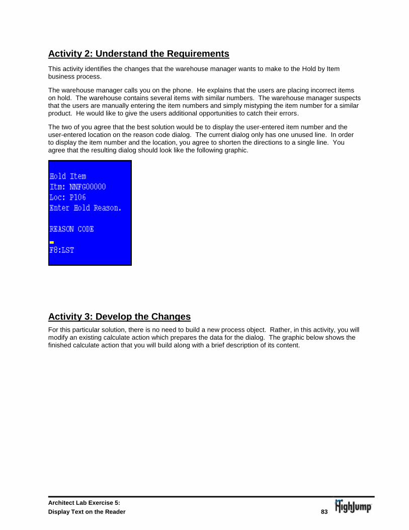
Architect Lab Exercise 5:
Display Text on the Reader 83
Activity 2: Understand the Requirements
This activity identifies the changes that the warehouse manager wants to make to the Hold by Item business process.
The warehouse manager calls you on the phone. He explains that the users are placing incorrect items on hold. The warehouse contains several items with similar numbers. The warehouse manager suspects that the users are manually entering the item numbers and simply mistyping the item number for a similar product. He would like to give the users additional opportunities to catch their errors.
The two of you agree that the best solution would be to display the user-entered item number and the user-entered location on the reason code dialog. The current dialog only has one unused line. In order to display the item number and the location, you agree to shorten the directions to a single line. You agree that the resulting dialog should look like the following graphic.
Activity 3: Develop the Changes
For this particular solution, there is no need to build a new process object. Rather, in this activity, you will modify an existing calculate action which prepares the data for the dialog. The graphic below shows the finished calculate action that you will build along with a brief description of its content.

Architect Lab Exercise 5:
Display Text on the Reader 84
Field Value Description
Dialog Type PROMPT Dictates the behavior of the dialog.
Dialog Prompt
REASON CODE Display on the screen.
SCR_HELP1 Itm: NNFG00000 Display on the screen.
SCR_HELP2 Loc: P106 Display on the screen.
SCR_HELP3 Enter Hold Reason. Display on the screen.
Before you make any changes to the objects in the application, it is beneficial to have a high-level understanding of how the Warehouse Advantage base application handles dialogs. Perform the following procedures to learn about the components of the base application that manage dialogs.
In Advantage Architect, double click WA in the Repository tab.
Choose the Define | Process Object menu option.
Double click the Dialog node.
The system opens the definition of the Dialog process object.

Architect Lab Exercise 5:
Display Text on the Reader 85
This process object is the driver for all dialogs in the Warehouse Advantage base application. Any time the system displays a screen (dialog) to the end user, it uses this process object. The dialog actions (which present the screen to the user) and the screen formats (which dictate the positioning of the text) are buried within the child process objects. The process object is written in a generic manner so that you do not need to understand all of the details in order to utilize its functionality. If you populate 12 fields and then call this process object, the underlying process objects will determine how to best position the data on the screen. Then they will present the screen to the end user. You are responsible for 12 fields. The Dialog process object in the base application handles the rest. The chart below shows the 12 fields the Dialog process object uses when it determines how to present the screen to the user.
Field Purpose
Dialog Type This field dictates the behavior of the dialog. It holds one of the following values:
CONFIRM – Displays information. The user responds with a Yes or No.
LIST – Displays a list. The user responds by selecting a number associated with one of the list entries.
NOPROMPT – Displays information. The user responds with one of the displayed function keys.
PROMPT – Directs the user to scan or enter a value. The user responds by scanning or entering a value.
Dialog Field The default value. If you populate this field, the system will display the Dialog Field where the cursor appears. If you press the enter key at the dialog with no additional input, the system uses the Dialog Field as the input value.
Dialog Prompt The prompt text.
SCR_HELP The instructions for the user. If necessary, the system wraps this field around multiple lines on the screen. If you populate this field, the system will ignore any values in the SCR_HELPx fields listed in the next row of this chart.

Architect Lab Exercise 5:
Display Text on the Reader 86
SCR_HELP1, SCR_HELP2, SCR_HELP3, SCR_HELP4, SCR_HELP5
The instructions for the user. The fields may also contain additional information beneficial to the user. The system will display each of these fields on its own unique line on the screen. If you want to utilize these fields, then you must set the SCR_HELP field to an empty value.
SCR_OPTIONS The function key text.
SCR_HEADING The name of the business process. The system typically displays this value on line 1 of the display.
SYS_SHORTMSG The error message, if necessary.
The base application standards dictate that when you display a screen to the end user, you should populate most of these 12 fields in a single calculate action. The standards also dictate that the name of the calculate action should begin with the characters: “Scr:Txt” In the procedures below you will look at an existing Scr:Txt calculate action and the resulting screen on the Virtual Terminal.
In Advantage Architect, choose the Define | Calculate menu option.
Double click the ScrTxt: Enter Control Number node.
On the Virtual Terminal, enter option 1 (the Receipts menu)
Enter 2 (the Transfers menu)
Enter 2 (the Transfer In menu)
The graphics below show the calculate action and the resulting screen on the Virtual Terminal along with a brief description of the relationship.

Architect Lab Exercise 5:
Display Text on the Reader 87
Field Value Details
Dialog Type PROMPT Indicates that the user will scan or enter a value at a prompt. The system does not display this field on the screen.
Dialog Field <Empty> There is no default control number, so this field remains empty.
Dialog Prompt CONTROL NUMBER The system displays the value on line 7 of the screen.
SCR_HELP Enter the Control Number
The system displays the value on lines 3 and 4 of the screen.
SCR_HELP1, SCR_HELP2, SCR_HELP3, SCR_HELP4, SCR_HELP5
<Empty> Because the SCR_HELP field is populated, the system will ignore any values for these fields. Architect initializes them to empty.
SCR_OPTIONS <Empty> There are no function keys to display on the screen, so this field remains empty.
SCR_HEADING Blind Transfer In The system displays the value on line 1. The system populates this field outside of the calculate action.
SYS_SHORTMSG <Empty> There is no error message to display, so this field remains empty. If there was an error, the system would populate the field outside of the calculate action.
You have seen the Dialog process object in the base application which drives all of the screens presented to the end user. And you have seen an example of a calculate action which prepares the data for the Dialog process object. Now you will apply this knowledge in the Hold by Item process. Perform the

Architect Lab Exercise 5:
Display Text on the Reader 88
following procedures to modify the display of the Reason Code dialog according to the warehouse manager’s requirements.
In Advantage Architect, choose the View | Close All menu option.
Choose the Define | Process Object menu option.
Double click the Hold by Item node. The system opens the current definition of the process object. This process object is the top-level object which contains all rules for the Hold by Item business logic. One of the keys to making this change is to find the logic in this process which prompts for the reason code. Naming conventions will be discussed later in this class. However, even without knowing naming conventions, you could probably guess that line 10 of this process object is somehow related to capturing a reason code from the end user. The Label edit box (REASON) and the Action Name drop down box (QC Hold - Reason) of line 10 are good indicators of the nature of the underlying logic.
Click the Action Name column of line 10 (Call…QC Hold - Reason) to bring focus.
Double click the Action Name column of line 10 (Call…QC Hold - Reason).
The system opens the definition of the process object. This process object contains all of the logic in the Hold by Item business process that relates to capturing a reason code from the end user. The graphic below shows the current definition of the process object and a brief description of its content.

Architect Lab Exercise 5:
Display Text on the Reader 89
Line Number Description
1 Populates a field which is used to determine the relevant reason code values from the t_reason database table.
2 Populates the fields which indicate the behavior of the screen and the text that appears on the screen. (See the first portion of this activity for a more detailed description.)
3 Populates the SCR_OPTIONS field with F8:Lst – a valid function key on this screen. The system will display this field on the bottom of the screen.
4 Populates a local variable. This is an advanced concept and is not discussed in this class.
5 Calls the Dialog process object. This process object determines the best layout for the screen based upon the fields populated in line 2 and line 3. Then it presents the screen to the user and waits for the user to respond.
Based upon the naming conventions mentioned above, line 2 contains the logic which prepares the data that will eventually be displayed on the screen.
Click the Action Name column of line 2 (Calculate…ScrTxt: Enter Reason for Hold) to bring focus.
Double click the Action Name column of line 2 (Calculate…ScrTxt: Enter Reason for Hold)
The system opens the definition of the calculate action.

Architect Lab Exercise 5:
Display Text on the Reader 90
Because the SCR_HELP field is populated, the system ignores the SCR_HELPX fields and it uses as many lines as necessary to display the SCR_HELP field. With the new screen, the system-determined line break logic needs to change. In the finished version, each of the display elements is displayed on exactly one line. You need to control the line breaks – not the system. In order to accomplish this, you will set the SCR_HELP field to empty and use the SCR_HELP1, SCR_HELP2, and SCR_HELP3 fields instead. The graphics below show the finished screen as well as how each SCR_HELP field will be utilized.
Also note that the text of the finished directive to the user is different from the value used in the base application. In the base application, the directive is “Enter a Reason for Hold”. In the finished version it is “Enter Hold Reason.” Because of the limited data on the screen, the base application version can consume two lines for the text. However, in the finished version, you are using SCR_HELP3 for the directives to the user. The system will use exactly one line to display this field. Therefore, you must shorten the directive to fit within one line.
Field Purpose in Finished Version
SCR_HELP <Empty>
SCR_HELP1 Item-related information
SCR_HELP2 Location-related information
SCR_HELP3 The directions to the user.
SCR_HELP4 <Empty>
SCR_HELP5 <Empty>
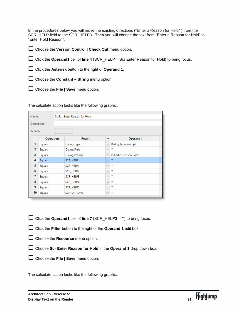
Architect Lab Exercise 5:
Display Text on the Reader 91
In the procedures below you will move the existing directions (“Enter a Reason for Hold” ) from the SCR_HELP field to the SCR_HELP3. Then you will change the text from “Enter a Reason for Hold” to “Enter Hold Reason”.
Choose the Version Control | Check Out menu option.
Click the Operand1 cell of line 4 (SCR_HELP = Scr Enter Reason for Hold) to bring focus.
Click the Asterisk button to the right of Operand 1.
Choose the Constant – String menu option.
Choose the File | Save menu option.
The calculate action looks like the following graphic.
Click the Operand1 cell of line 7 (SCR_HELP3 = “”) to bring focus.
Click the Filter button to the right of the Operand 1 edit box.
Choose the Resource menu option.
Choose Scr Enter Reason for Hold in the Operand 1 drop down box.
Choose the File | Save menu option.
The calculate action looks like the following graphic.
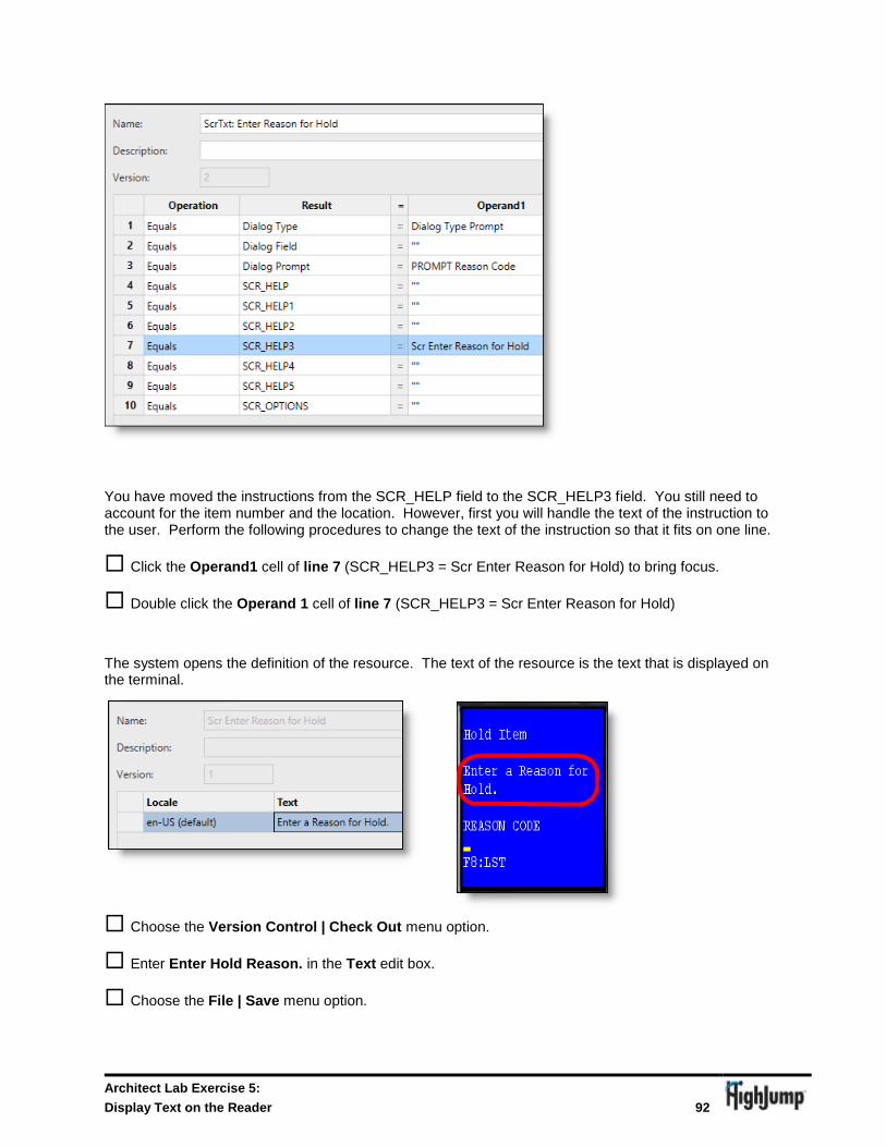
Architect Lab Exercise 5:
Display Text on the Reader 92
You have moved the instructions from the SCR_HELP field to the SCR_HELP3 field. You still need to account for the item number and the location. However, first you will handle the text of the instruction to the user. Perform the following procedures to change the text of the instruction so that it fits on one line.
Click the Operand1 cell of line 7 (SCR_HELP3 = Scr Enter Reason for Hold) to bring focus.
Double click the Operand 1 cell of line 7 (SCR_HELP3 = Scr Enter Reason for Hold)
The system opens the definition of the resource. The text of the resource is the text that is displayed on the terminal.
Choose the Version Control | Check Out menu option.
Enter Enter Hold Reason. in the Text edit box.
Choose the File | Save menu option.

Architect Lab Exercise 5:
Display Text on the Reader 93
The finished resource looks like the following graphic.
You have made all of the necessary changes related to the instruction for the user. Next you will work with the item number. While there are a couple item-related resources in the base application, none of them fit the exact requirements. You need to create a new resource.
Choose the Define | Resource menu option.
Choose the File | New menu option.
Enter Scr Itm: Item ID in the Name edit box.
Enter Itm: ~Item ID~ in the Text edit box.
Choose the File | Save menu option.
The finished resource looks like the following graphic.
The Text edit box contains the text that displays on the terminal. It contains both constant and dynamic data. “Itm: “ is the constant portion of the resource. Regardless of the situation, when you instruct the system to display this resource it will always display the constant text “Itm:” However, “~Item ID~” is dynamic data, and it refers to the current value of the Item ID field (defined in Advantage Architect). The surrounding tildes is the syntax to indicate a reference to an Architect field. At runtime, the system looks up the value of the Item ID field in memory; replaces ~Item ID~ with the value; then displays the resulting resource on the terminal. The chart below gives a couple examples of how this resource might render on the terminal.

Architect Lab Exercise 5:
Display Text on the Reader 94
Value of Item ID field Text displayed on terminal
NNFG00000 Itm: NNFG00000
INSP07505 Itm: INSP07505
NNRM85001 Itm: NNRM85001
You have created a new resource. However, if you do nothing else, the system will not display the resource on the screen. The resource must be associated with a field in order to display it on the screen. Follow the procedures below to associate the resource with a field.
Click the ScrTxt: Enter Reason for Hold tab (calculate action) along the top of the tool.
Click the Operand1 cell of line 5 (SCR_HELP1 = “”) to bring focus.
Click the Filter button to the right of the Operand 1 edit box.
Choose the Resource menu option.
Choose Scr Itm: Item ID in the Operand 1 drop down box.
Choose the File | Save menu option.
The calculate action looks like the following graphic.

Architect Lab Exercise 5:
Display Text on the Reader 95
You have accounted for the instruction that the system displays to the user. And you have accounted for the item number. The final component is the location which you will associate with the SCR_HELP2 field.
The base application contains a location-related resource which meets the warehouse manager’s requirements. Rather than creating a new resource, you will utilize the one from the base application.
Choose the Define | Resource menu option.
Double click the Scr Loc: Location node.
The system displays the definition of the resource.
Similar to the item-related resource, the location-related resource contains both constant data and dynamic data. “Loc” is the constant data. And “~Location~” is the dynamic data which refers to the current value of the Location field which was defined in Advantage Architect. This resource meets the warehouse manager’s requirements and you can use it without any modifications.
You have identified an existing resource which you can use. Next you will associate this resource with the SCR_HELP2 field in the calculate action which prepares the data for the screen.
Click the ScrTxt: Enter Reason for Hold tab (calculate action) along the top of the tool.
Click the Operand1 cell of line 6 (SCR_HELP2 = “”) to bring focus.
Click the Filter button to the right of the Operand 1 edit box.
Choose the Resource menu option.
Choose Scr Loc: Location in the Operand 1 drop down box.
Choose the File | Save menu option.
The calculate action looks like the following graphic.

Architect Lab Exercise 5:
Display Text on the Reader 96
You have made all of the necessary changes to the Advantage Architect objects in order to the meet the warehouse manager’s requirements. Now it is time to compile and activate the application.
Activity 4: Compile and Activate the Changes
At this point you have modified several objects to meet the requirements dictated by the warehouse manager. However, if you view the Virtual Terminal, you will see that the changes have had no impact. In order to see the changes reflected on the Virtual Terminal, you must first compile the application and then activate the application. The procedures below are very generic. If you need additional details on how to compile and activate the application, please see the activity titled Compile and Activate the Changes in Exercise 1 of this manual.
Compile the application
Activate the application
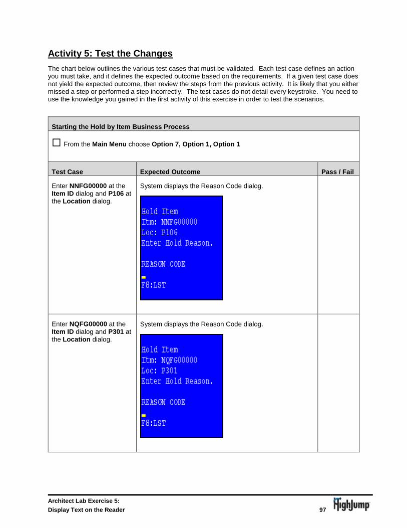
Architect Lab Exercise 5:
Display Text on the Reader 97
Activity 5: Test the Changes
The chart below outlines the various test cases that must be validated. Each test case defines an action you must take, and it defines the expected outcome based on the requirements. If a given test case does not yield the expected outcome, then review the steps from the previous activity. It is likely that you either missed a step or performed a step incorrectly. The test cases do not detail every keystroke. You need to use the knowledge you gained in the first activity of this exercise in order to test the scenarios.
Starting the Hold by Item Business Process
From the Main Menu choose Option 7, Option 1, Option 1
Test Case Expected Outcome Pass / Fail
Enter NNFG00000 at the Item ID dialog and P106 at the Location dialog.
System displays the Reason Code dialog.
Enter NQFG00000 at the Item ID dialog and P301 at the Location dialog.
System displays the Reason Code dialog.

Architect Lab Exercise 5:
Display Text on the Reader 98
Activity 6: Check in the Objects
Earlier in this exercise, you checked out several objects and made changes to them. As long as the objects are checked out in your name, you are the only developer who can alter their definitions. Because your changes met the warehouse manager’s requirements, you can make the objects available to other Architect developers in your company. In the steps below, you will check in the objects so that other developers can make additional changes to them.
Choose the View | Close All menu option.
Check in all of the objects.

Admin Lab Exercise 6:
Visual Debugger 99
Admin Lab Exercise 6: Visual Debugger
Introduction This exercise consists of the following activities:
1. Understand the Current Process
2. Explore the Visual Debugger
3. Add a Watch to Visual Debugger
4. Add a Breakpoint to Visual Debugger
5. Use the Message Watch Feature of Visual Debugger
6. Use the Record Feature of Visual Debugger
7. View the Call Stack
8. View a List
Background Information Visual Debugger is a tool that allows you to troubleshoot the business logic (workflows) of your Advantage applications. Technically speaking, Visual Debugger is a tool that allows you to troubleshoot the process objects that were created in Advantage Architect.
The concept of a process object is described in great detail during the Advantage Architect class. For the purposes of this class, a process object is defined as “a set of executable steps designed to accomplish a specific purpose.” They are created in a development tool called Advantage Architect. For example, one process object might prompt the user for an order number. Another process object might retrieve all order master data from the database for a given order number. Each step in the process object returns either a PASS or FAIL status.
Developers use this tool extensively to debug logic problems in the application. However, as an administrator you will use it primarily under the direction of the HighJump support team. They may ask you to capture some information and send it to them via e-mail. Or they may ask you to run the Visual Debugger and then explain what you see in certain windows.
Regardless of the mode you use when you run Visual Debugger, it will always have a negative impact on the performance of the terminal to which it is attached. It is a good idea to set that expectation with the user who is running the terminal.
Before performing this exercise, we recommend you use the Troubleshooting Advantage System Pre-Work link and review the related video demonstrations under the Debugger menu. (The link is located on the right side panel of the VLab interface.)

Admin Lab Exercise 6:
Visual Debugger 100
Activity 1: Understand the Current Process
This activity demonstrates how the Location Status process operates in the Warehouse Advantage base application. This business process will be used as a foundation for learning about the Visual Debugger tool. The Location Status process manages the viewing and/or modification of a specific location's status. The user is first prompted to scan the location to be viewed or modified. The location’s current status is then displayed and the user can enter a new status. The possible location status codes are listed below.
Status Description
E Empty location, where there is no inventory associated to the location.
P Partial location, where there is at least one item in the location and the location has not reached a user-determined capacity.
F Full location, where there is at least one item in the location and the location has reached a user-determined capacity.
I Inactive location, where the location and associated inventory are not available for put-away and picking.
After a new status is entered by the user the system updates the location's status with the identified status and a location status transaction is generated.
Log in to the Virtual Terminal as AMY / AMY / FAAMY.
Press the F8 key to scroll down a page.
Enter option 7 (the Inv Control menu.)
Enter option 3 (the Inventory Status menu.)
Enter option 4 (the Location Status menu.)
The system displays the Location screen.
Enter I171 at the Location dialog.

Admin Lab Exercise 6:
Visual Debugger 101
The system displays the location and the current status (empty) at the top of the location status screen.
Enter I at the Location Status dialog.
The system updates the status of the location in the location master table, and then loops back to the top of the business process. The system now gives the user an opportunity to view or modify the status of another location.
In this example, you will set the status of I171 back to empty.
Enter I171 at the Location dialog.
The system displays the location and the current status (inactive) at the top of the location status screen.

Admin Lab Exercise 6:
Visual Debugger 102
Enter E at the Location Status dialog.
The system updates the status of the location in the location master table, and then loops back to the top of the business process. The system now gives the user an opportunity to view or modify the status of another location.
Press the F1 key to navigate back to the Inventory Status menu.
Press the F1 key to return to the Inv Control menu.
Press the F1 key to return to the main menu.

Admin Lab Exercise 6:
Visual Debugger 103
Activity 2: Explore the Visual Debugger
Scenario: You recently contracted with HighJump Software to make some changes to the Location Status business process. After promoting the change into production, one of your managers indicates that the data the HighJump system is sending to the host system for this business process is no longer correct. You call the HighJump support team, and they ask you to start the Visual Debugger, walk through a couple steps line by line, and then verbally describe what you see.
Procedures: The procedures below demonstrate how to start the Visual Debugger and how to step through each line of a process objects. However, they do not reproduce the problem with the incorrect data going to the host system.
Configure the Device Name parameter of the Virtual Terminal to RADIO_01, if necessary.
Navigate to the Location prompt of the Location Status business process.
Choose the Start | All Programs | HighJump Software | Visual Debugger menu.
The system displays the main screen of the Visual Debugger. In the initial state, the window is empty. The Visual Debugger window will remain empty until you connect it to a specific application server and a specific device.
Choose the File | Connect to Application Server menu.
The system displays a dialog for entering the connection information to the application server.

Admin Lab Exercise 6:
Visual Debugger 104
In this specific example, the Visual Debugger resides on the same machine as the application server. This is defined as a local connection. The system also provides two additional methods (IPC and TCP/IP) for connecting to a remote application server. For additional information on these other methods, see the Visual Debugger help files.
Choose the Local radio button.
Click the OK button.
The system changes the title bar of the window to indicate that it successfully connected to the application server. However, it is still not attached to a specific device, and the main window remains empty.
Choose the File | Select Device menu.
The system displays a drop-down list of all possible devices that can be debugged. The list includes Virtual Terminals, Web Terminals, physical RF terminals, as well as other items that run process objects.
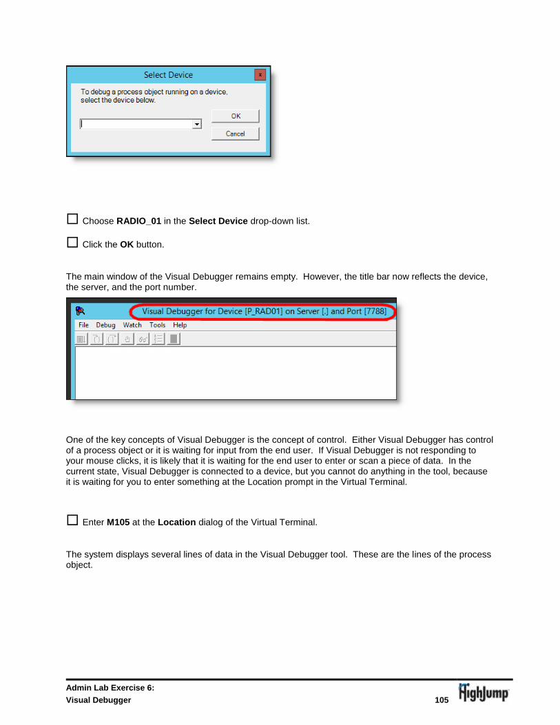
Admin Lab Exercise 6:
Visual Debugger 105
Choose RADIO_01 in the Select Device drop-down list.
Click the OK button.
The main window of the Visual Debugger remains empty. However, the title bar now reflects the device, the server, and the port number.
One of the key concepts of Visual Debugger is the concept of control. Either Visual Debugger has control of a process object or it is waiting for input from the end user. If Visual Debugger is not responding to your mouse clicks, it is likely that it is waiting for the end user to enter or scan a piece of data. In the current state, Visual Debugger is connected to a device, but you cannot do anything in the tool, because it is waiting for you to enter something at the Location prompt in the Virtual Terminal.
Enter M105 at the Location dialog of the Virtual Terminal.
The system displays several lines of data in the Visual Debugger tool. These are the lines of the process object.

Admin Lab Exercise 6:
Visual Debugger 106
At this point Visual Debugger has control of the process, and it is waiting for you to step through it line by line. Additionally, the Virtual Terminal remains on the LOCATION dialog. If the device was a physical RF radio, then the screen would eventually read “Advantage Engine Down.” The yellow arrow points to the line number which the system will execute next. If you want to execute that one line, then you can use the “Step Into” feature.
Choose the Debug | Step Into menu in the Visual Debugger.
The system executes that one line; advances the yellow arrow to the next line that will be executed; and then Visual Debugger stops. In this case, the process object also changes so the display in the top panel of Visual Debugger also changes.
This second button from the left is the equivalent of the Debug | Step Into menu. For the purpose of this document, it will be referred to as the Step Into button.
Click the second button from the left in the Visual Debugger.
Once again, the system executes that one line; advances the yellow arrow to the next line that will be executed; and then Visual Debugger stops. In this case, the process object also changes so the display in the top panel of Visual Debugger also changes.

Admin Lab Exercise 6:
Visual Debugger 107
Click the Messages tab along the bottom of Visual Debugger.
Click the Step Into button of Visual Debugger multiple times until the Virtual Terminal displays the Location Status dialog.
As you step through the process object lines, the system displays each executed line in the bottom pane along with the returned status of each line (PASSED or FAILED). A status of FAILED does not necessarily mean that something is wrong. Often times a FAILED status is the expected result.
Click the Step Into button of Visual Debugger one more time.
The system displays the following warning. The text of the warning indicates that Visual Debugger is waiting for input at the Virtual Terminal. The fix is to acknowledge the warning, and then enter data at the terminal.

Admin Lab Exercise 6:
Visual Debugger 108
Click the OK button.
Enter P at the Location Status dialog of the Virtual Terminal.
At this point, you can step to the appropriate line as directed by the HighJump support team, and then read them the information you see on the screen. Once they have the necessary information, you need to exit the debugger which will return the terminal back to normal operation.
Click the Step Into button of Visual Debugger a couple more times.
You are done utilizing the Step Into feature, so now you will exit the tool.
Choose the File | Detach Debugger menu in Visual Debugger.
The system closes the Visual Debugger. The Virtual Terminal advances to next prompt. And Virtual Terminal returns to normal operation. There may be times when you choose the File | Detach Debugger menu and the system does nothing. This is most likely because the debugger is waiting for input from the user. If this is the case, then enter data at the Virtual Terminal, and then the debugger will disappear.
In Virtual Terminal, navigate back to the menu.

Admin Lab Exercise 6:
Visual Debugger 109
Activity 3: Add a Watch
Background: The Visual Debugger tool provides the ability to look at the value of a variable in memory. This is an important aspect of the troubleshooting process as it allows you to see exactly which line modifies a given variable. The concept of looking at the value of a variable through the lens of Visual Debugger is called a “Watch”.
Scenario: This scenario builds upon the one from the previous activity. The HighJump support team has reviewed the data you read to them, but they have not found the root cause of the problem. They want you to set a Watch on the Location variable, the Status variable, and the Transaction Code variable in order to assist with the troubleshooting process.
Procedures: The procedures below demonstrate how to add a Watch to Visual Debugger. However, they do not reproduce the problem with the incorrect data going to the host system.
Open the Virtual Terminal, if necessary.
Navigate to the Location prompt of the Location Status business process.
Open the Visual Debugger.
Attach the Visual Debugger to the Virtual Terminal.
Enter M106 at the Location prompt of the Virtual Terminal.
The system displays several lines of the current process object.
Click the Watch Fields tab along the bottom of the Visual Debugger.
The system displays a list of all of the currently defined Watch variables in the lower pane. In this case, there are none.

Admin Lab Exercise 6:
Visual Debugger 110
Choose the Watch | Add Field menu.
The system displays the Add Watch window.
Choose Location in the Fields in WA drop-down list.
Click the OK button.
The system adds the Location variable to the lower pane, and it displays the current value of the Location variable. In this case, the current value is empty.
In this example you will watch two additional fields: Status and Transaction Code.
Choose the Watch | Add Field menu.
Choose Status in the Fields in WA drop-down list.
Click the OK button.

Admin Lab Exercise 6:
Visual Debugger 111
The system adds the Status variable to the lower pane, and it displays the current value of the Status variable. In this case, the current value is empty.
Choose the Watch | Add Field menu.
Choose Transaction Code in the Fields in WA drop-down list.
Click the OK button.
The system adds the Transaction Code variable to the lower pane, and it displays the current value of the Transaction Code variable. In this case, the current value is 900 which uniquely identifies the Location Status business process.
Click the Step Into button of Visual Debugger four times.
At this point in the logic, the system updates the Location field to the value entered by the end user on the Virtual Terminal. The bottom panel of Visual Debugger reflects this change and displays the newly changed field value in red.
Click the Step Into button of Visual Debugger thirteen times.

Admin Lab Exercise 6:
Visual Debugger 112
At this point in the logic, the system updates the Status field to the status of the given location as defined in the location master database table. (In this case, the status is E.) The bottom panel of Visual Debugger reflects this change and displays the newly changed field value in red.
You are done utilizing the Watch feature, so now you will exit the tool.
Choose the File | Detach Debugger menu in Visual Debugger.
The system closes the Visual Debugger. The Virtual Terminal advances to next prompt. And Virtual Terminal returns to normal operation.
In Virtual Terminal, navigate back to the menu.

Admin Lab Exercise 6:
Visual Debugger 113
Activity 4: Add a Breakpoint
Background: A breakpoint allows you to stop the execution of a process object at a specific line number. You set a breakpoint near the place where you suspect the error. Then you run the business process from the terminal. The terminal will run normally, but slowly, until it reaches the breakpoint. When it reaches the breakpoint, the Visual Debugger captures control of the business process. Then you can step through the process object lines one by one, just like you did in a previous activity.
Scenario: This scenario builds upon the one from the previous activity. The HighJump support team has reviewed the watch variable information you read to them, but they have not found the root cause of the problem. They suspect the problem is inside a process object called “Log – Location Status”. They ask you to set a breakpoint in this process object in order to assist with the troubleshooting process.
Procedures: The procedures below demonstrate how to add a breakpoint to Visual Debugger. However, they do not reproduce the problem with the incorrect data going to the host system.
Open the Virtual Terminal, if necessary.
Navigate to the User ID prompt of the Logon process.
Open the Visual Debugger.
Attach the Visual Debugger to the Virtual Terminal.
Enter a user at the User ID prompt of the Virtual Terminal
The system displays several lines of the current process object.
Choose the Debug | New Breakpoint menu in Visual Debugger.
The system opens the Add a Breakpoint window.

Admin Lab Exercise 6:
Visual Debugger 114
Choose Log – Location Status in the Process Object drop-down list.
Click the Get button.
The system displays the definition of the Log – Location Status process object.
Double click in the white space to the left of the number 9.
The system places a stop sign icon to the left of the selected line. The stop sign indicates the breakpoint.
Click the Done button.
Choose the Debug | Go menu.
When you click the Go menu, the Virtual Terminal will run normally until it encounters a breakpoint or until you click the Step Into button of the Visual Debugger.

Admin Lab Exercise 6:
Visual Debugger 115
Navigate to the Location Status prompt of the Location Status business process in the Virtual Terminal.
The Virtual Terminal runs normally, but slowly. There is no activity in the top pane of the Visual Debugger. And the Messages tab of Visual Debugger is empty. The system has not encountered the breakpoint yet.
Enter a status at the Location Status dialog on the Virtual Terminal.
The Virtual Terminal does not advance to the next prompt. Additionally, the top pane of the Visual Debugger window displays the definition of the Log – Location Status process object. The yellow arrow, which indicates the next line the system will execute, is standing on the line number 9. Visual Debugger has finally reached the breakpoint. You can still see the icon.
At this point Visual Debugger has control of the process, and it is waiting for you to step through it line by line. It is in the same state it was during the first activity. You can use the Step Into button to walk through the lines one by one.
Click the Step Into button several times.
Visual Debugger will maintain the definition of this breakpoint even after you stop and start the tool again, unless you tell it otherwise. You can remove all breakpoint definitions through a menu option. (You can disable an individual one by finding the “stop sign” icon you created earlier and double clicking on it.) In this example you will disable all of the breakpoints.
Choose the Debug | Clear All Breakpoints menu.
You are done utilizing the Breakpoint feature, so now you will exit the tool.
Choose the File | Detach Debugger menu in Visual Debugger.
The system closes the Visual Debugger. The Virtual Terminal advances to next prompt. And Virtual Terminal returns to normal operation.

Admin Lab Exercise 6:
Visual Debugger 116
In Virtual Terminal, navigate back to the menu.

Admin Lab Exercise 6:
Visual Debugger 117
Activity 5: Use the Message Watch
Background: In a previous activity, you displayed the line-by-line output in the messages tab of the lower pane of Visual Debugger. You did this by using the Step Into button. However, if you are only interested in viewing the line-by-line output, then the Step Into button is not very efficient. The Step Into button only gives you one line of output per mouse click. The Message Watch solves this problem. The Message Watch feature allows you to view a multitude of line-by-line outputs with only a couple mouse clicks.
Scenario: This scenario builds upon the one from the previous activity. The HighJump support team has analyzed the information you read to them related to the breakpoint, but they have not found the root cause of the problem. They ask you to run several iterations of the Location Status business process, and then send them the line-by-line output for each iteration.
Procedures: The procedures below demonstrate how to enable the Message Watch feature. However, they do not reproduce the problem with the incorrect data going to the host system.
Open the Virtual Terminal, if necessary.
Navigate to the Location prompt of the Location Status business process.
Open the Visual Debugger.
Attach the Visual Debugger to the Virtual Terminal.
Enter a location at the Location prompt of the Virtual Terminal.
The system displays several lines of the current process object.
Click the Messages tab along the bottom of the Visual Debugger.
The system displays the current line-by-line output.

Admin Lab Exercise 6:
Visual Debugger 118
Choose the Tools | Message Watch menu.
There are no immediate visual cues that you have enabled Message Watch mode. However, if you return to the Tools menu, you will see a checkmark next to the Message Watch menu. This indicates that Message Watch mode has been enabled.
Choose the Debug | Go menu.
As the system executes a line of code it outputs one or more lines of data to the Messages tab. It will do this continuously until you manually disable the Message Watch mode or until you shut down Visual Debugger. The performance of the Virtual Terminal is significantly slower when the Message Watch is enabled. However it does advance to the next prompt after you enter a piece of data.
Perform a couple iterations of the Location Status business process on the Virtual Terminal.
The system continues to scroll the line-by-line output to the messages tab.

Admin Lab Exercise 6:
Visual Debugger 119
After you have captured the desired line-by-line output, you can copy the data out of the messages tab and paste it into another document.
Create a new text file on the desktop.
Open the text file with Notepad.
Highlight multiple rows in the Message tab of Visual Debugger with a click and drag methodology.
Press the Control C combination of keys on the keyboard.
Choose the Edit | Paste menu in the Notepad application
The system pastes the text from the Visual Debugger into the Notepad application.
Choose the File | Save menu in the Notepad application
Choose the File | Exit menu in the Notepad application
At this point you could send the text file to the HighJump support team for further analysis. You are done utilizing the Message Watch feature, so now you will exit the tool.
Choose the File | Detach Debugger menu in Visual Debugger.
The system closes the Visual Debugger. The Virtual Terminal advances to next prompt. And Virtual Terminal returns to normal operation.
In Virtual Terminal, navigate back to the menu.

Admin Lab Exercise 6:
Visual Debugger 120
Activity 6: Use the Record Feature
Background: The Record feature of Visual Debugger operates similarly to the Message Watch feature. It maintains the continuous stream of line-by-line output while the terminal runs in a normal mode. However, the Record feature does not direct the line-by-line output to the Messages tab. Instead, it writes the line-by-line output directly to a text file. This simplifies the process of extracting the line-by-line output from Visual Debugger.
Scenario: This scenario is identical to the one from the previous activity. However, you know that you want to capture the line-by-line output and send it to the HighJump support team in a Notepad document. Since the Record feature simplifies the extraction process, you opt to use the Record features instead of the Message Watch feature.
Procedures: The procedures below demonstrate how to enable the Record feature. However, they do not reproduce the problem with the incorrect data going to the host system.
Open the Virtual Terminal, if necessary.
Navigate to the Location prompt of the Location Status business process.
Open the Visual Debugger.
Attach the Visual Debugger to the Virtual Terminal.
Enter a location at the Location prompt of the Virtual Terminal.
The system displays several lines of the current process object.
Click the Messages tab along the bottom of the Visual Debugger.
The system displays the current line-by-line output.
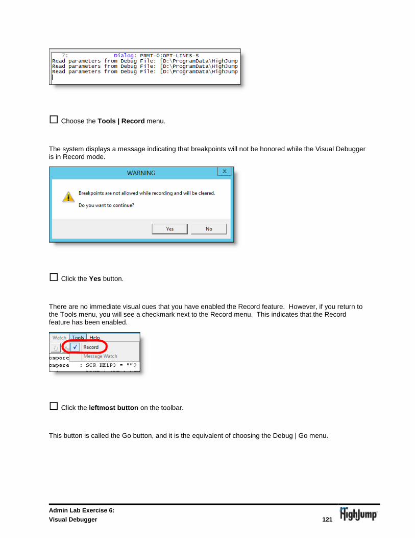
Admin Lab Exercise 6:
Visual Debugger 121
Choose the Tools | Record menu.
The system displays a message indicating that breakpoints will not be honored while the Visual Debugger is in Record mode.
Click the Yes button.
There are no immediate visual cues that you have enabled the Record feature. However, if you return to the Tools menu, you will see a checkmark next to the Record menu. This indicates that the Record feature has been enabled.
Click the leftmost button on the toolbar.
This button is called the Go button, and it is the equivalent of choosing the Debug | Go menu.

Admin Lab Exercise 6:
Visual Debugger 122
Perform a couple iterations of the Location Status business process on the Virtual Terminal.
The Virtual Terminal runs slowly, but it advances to the next prompt every time you enter a piece of data. However, Visual Debugger does not write any data to the messages tab. Behind the scenes Visual Debugger is writing the line-by-line output to a text file.
Choose the File | Detach Debugger menu.
Enter a value at the current prompt in the Virtual Terminal, if necessary, in order to close the Visual Debugger.
In Virtual Terminal, navigate back to the menu.
At this point, you have captured all of the necessary line-by-line output. Now, you can locate the text file and send it to the HighJump support team.
Open Windows Explorer.
Navigate to the D:\ProgramData\HighJump Software\CONTROL\CONTROL1 folder.
The name of the desired file begins with R_, and it contains the ID of the terminal and has an LOG extension. In this case the file name is R_RAD01_record.
Double-click the R_RAD01_record text file.

Admin Lab Exercise 6:
Visual Debugger 123
The system displays the line-by-line out from the Visual Debugger in the Notepad application.
Choose the File | Exit menu in the Notepad application.
At this point, you could zip the file if necessary, and then send it to the HighJump support team for further analysis.

Admin Lab Exercise 6:
Visual Debugger 124
Activity 7: View the Call Stack
Background: Every business process which runs on an RF terminal is configured in Advantage Architect using a series of process objects. These process objects are built in layers in which the top-level process object calls a 2nd-level process object which calls a 3rd-level process object. This pattern can continue for several layers depending on the complexity of the requirements.
When debugging an issue with a business process, it is often beneficial to know the name of the current process object which is being executed as well as the names of all the other process objects which are layered above it. The list of the layered process objects is called a call stack. Visual Debugger, as well as the AWESM tool, have features that display the process object call stack.
Procedures: Perform the following procedures to view the process object call stack in Visual Debugger and in the AWESM tool.
Open the Virtual Terminal, if necessary.
Navigate to the Location prompt of the Location Status business process.
Open Visual Debugger.
Attach Visual Debugger to the Virtual Terminal
Enter M103 at the Location prompt of the Virtual Terminal.
The system displays several lines of the current process object in Visual Debugger.
Click the Call Stack tab along the bottom of the Visual Debugger.
Visual Debugger displays the process object call stack. The name of the current process object is positioned at the top of the list. The first process object is positioned at the bottom of the list. In this example, the current process object is 10 layers deep.

Admin Lab Exercise 6:
Visual Debugger 125
If the only information you want to capture is the process object call stack, then the above methodology is a bit lengthy. The methodology requires you to open Visual Debugger; attach it to a terminal; and then respond to the screen on the terminal. The methodology works well if you are already in Visual Debugger for other purposes. However, the most efficient way to capture the process object call stack is to use the AWESM tool. Follow the procedures below to view the process object call stack in the AWESM tool.
Open the Advantage Workflow Engine Service Manager, if necessary.
Click the WA solution environment, in order to highlight it.
Click the Sessions button.
The system opens another window which displays all of the sessions for the WA solution environment.
Click the RADIO_01 device, in order to highlight it.
Click the Status button near the lower left corner of the window.
The system opens a large window that displays several status-related properties of RADIO_01. The system displays the process object call stack near the bottom of the window. Note that the call stack in the AWESM tool is the same information as the call stack in Visual Debugger.
Layer 1
Layer 10 (the current process object)
Layer 5

Admin Lab Exercise 6:
Visual Debugger 126
Sometimes when you are debugging a business process, it may be beneficial to copy the call stack information and send it to a third party for their analysis. The AWESM tool allows you to copy the call stack, but Visual Debugger does not. Follow the procedures below to copy the call stack and paste it into a Notepad file.
Highlight the entire contents of the Process Object Call Stack box in the AWESM tool using the mouse.
Right-click the selected text.
Choose the Copy menu option.
Open the Notepad application.
Choose the Edit | Paste menu option.
The system pastes the call stack information into Notepad.
Save the Notepad file to the desktop.
Close the Notepad application.
Click the “X” in the upper right corner of the Status for [RADIO_01] window to close it.
Click the “X” in the upper right corner of the Sessions – WA window to close it.
Choose the File | Detach Debugger menu.
Enter a value at the current prompt in the Virtual Terminal, if necessary, in order to close the Visual Debugger.
In Virtual Terminal, navigate back to the menu.
AWESM Visual Debugger

Admin Lab Exercise 6:
Visual Debugger 127
Activity 8: View a List
In some business processes, the system reads several records from the database, and then stores them in the memory of the application server. In these business processes, the system usually iterates through each record and then performs some work on each one. The collection of records which is stored in the memory of the application server is called a list. When debugging an issue with a business process, it may be beneficial to view the contents of a list.
The procedures below utilize a business process, called View by Item, which allows you to view all inventory locations containing a given item number. The business process uses a list to present the locations to the end user. Follow the procedures below to view the contents of the list used in the View by Item business process.
Open the Virtual Terminal, if necessary.
Navigate to the Main Menu screen.
Press the F8 key in order to page down to the next set of menu options.
Enter 7 (Inv Control) at the Option prompt.
Enter 3 (Inventory Status) at the Option prompt.
Enter 2 (View by Item) at the Option prompt.
The system advances to the first prompt of the View by Item business process.
Enter NNFG00000 at the ITEM ID prompt.
Behind the scenes, the systems retrieves several inventory-related records from the database and stores them in a list on the application server. The system then displays several inventory attributes of the first location containing the given item number.

Admin Lab Exercise 6:
Visual Debugger 128
Press the F8:Next key three times to navigate through the first three records.
Press the F4:Prev key three times to navigate back to the first record.
Open Visual Debugger.
Attach Visual Debugger to the Virtual Terminal
Press the F8:Next key on the Virtual Terminal to advance to the next location containing the item.
Visual Debugger grabs control of the business process and displays several lines of the current process object in Visual Debugger.
Now that Visual Debugger is attached to the terminal, you will view the contents of the list containing the inventory-related data.
Choose the Watch | Add List menu option.
The system displays the Add Watch List window and requires you to choose the name of the list. There are several lists displayed in the drop-down control. The name of the list is determined by the developer at the point of configuration. In this example the inventory-related information is stored in a list called View Inventory List.

Admin Lab Exercise 6:
Visual Debugger 129
Choose View Inventory List in the Lists in WA drop-down list.
Click the OK button.
The system displays the data in the list using a grid, and it displays several other attributes of the list immediately above the grid. Note that the data in row number 1 of the list is the same data on the Virtual Terminal. By default the system displays the first 10 rows of the list. But in this example there are a total of 28 rows in the list.
If you want to see more than 10 rows in the list, you can change the limit and then refresh the grid.
Enter 50 in the Limit edit box.
Click the Refresh button.
The system refreshes the data in the grid based upon the new settings. The system now displays a vertical scroll bar in the grid and allows you to view up to the first 50 rows in the list.

Admin Lab Exercise 6:
Visual Debugger 130
Depending on your Advantage Architect skills, it may be beneficial to copy the list information out of the grid and send it to a third party for their analysis.
Press and hold the Shift key.
Click anywhere in Row 6 to highlight the first 6 rows in the grid.
Press the Control-C keys to copy the selected text into the Windows clipboard.
Open the Notepad application.
Choose the Edit | Paste menu option.
The system pastes the data from the list into Notepad.
Save the Notepad file to the desktop.
Close the Notepad application.
Choose the File | Detach Debugger menu option in Visual Debugger to close it.
At this point you could send the text file to a colleague or a support team member for additional analysis.

Architect Lab Exercise 7:
Add a New Business Process 131
Architect Lab Exercise 7: Add a New Business Process
Introduction
In this exercise you will create a new business process which allows a user to perform an on demand cycle count at a location of his choice.
Background Information This exercise uses the concept of a cycle count as a basis for all activities. In order to ensure inventory accuracy in a warehouse, it is important to periodically count all of the inventory in the warehouse. One way to do this,is to shut down all warehouse operations for a couple days while the material handlers count the inventory. This, of course, is a very expensive solution as the warehouse is not operational during this time. Another solution is to count a subset of the inventory every day while the normal warehouse operations take place. This solution is called a cycle count, and it is much more practical than shutting down the entire warehouse operations.
The Warehouse Advantage base application contains a couple cycle count related business processes. However, all of the cycle count related business processes in the base app are system directed. This means that the system directs the user to a specific location to perform a cycle count. The system does not allow the user to indicate the location where he wants to perform a cycle count. The user must go to the location directed by the system.
Additionally, every process in the Warehouse Advantage base application writes a record to the t_tran_log table at the end of the process. The record contains all of the relevant pieces of data that were captured in the process along with timestamps and the user id. The t_tran_log table is highly valuable when you need to review the history of a given license plate or a given location.
The lectures from the class with a live instructor are posted online. If you are working in a self-directed VLab, review the following topics:
1. Open the Architect Online Lectures online course.
2. Review all Day 2 lectures.

Architect Lab Exercise 7:
Add a New Business Process 132
Activity 1: Understand the Current Process
This activity demonstrates the cycle count related business processes accessible on the RF terminal.
Log in to the Virtual Terminal as AMY / AMY / FAAMY.
Press the F8 key to scroll to the next page.
Enter option 7 (the Inv Control menu.)
Enter option 2 (the Cycle Counts menu.)
The system displays three available menu options. The Cycle Count option and the Cycle Count Check menu option are the two cycle counting processes included in the base application. In both of these processes, the system directs the user to a specific location and it does not allow the user to override the suggested location.

Architect Lab Exercise 7:
Add a New Business Process 133
Activity 2: Understand the Requirements
This activity identifies the changes that the warehouse manager wants to make to the cycle count business processes.
The warehouse manager calls you on the phone. He explains that they use the Cycle Count Check and the Cycle Count process every day to audit a subset of the inventory. However, he wants the ability to walk up to a location and cycle count it on demand. The current cycle count business processes do not allow an on-demand cycle count because the system always suggests a location and it does not allow overrides. The two of you discuss a couple possibilities. In the end you agree that a separate menu option for an on-demand cycle count is the best solution.
Activity 3: Develop the Changes
A production-ready cycle count process is highly involved and it goes beyond the scope of this class. The on-demand cycle count process that you will build in this exercise is not production-ready. It provides a simplistic framework which captures a minimal amount of data and writes it to a transaction log. It performs virtually no validation, and it does not modify inventory. It is used to demonstrate several concepts related to building a new business process. At a high level, this simplistic cycle count process performs the following steps: 1. Prompts for a Location and verifies the user-entered value against the location master table 2. Prompts for an Item Number and verifies the user-entered value against the item master table. 3. Prompts for the total Quantity of the item in the location. 4. Inserts a transaction into the transaction log table. 5. Displays a Transaction Complete message to the user. 6. Loops back to the location dialog In this activity you will create a new business process object that allows a user to perform an on-demand cycle count. The graphics below show the new menu on the RF terminal, the final top-level process object, and a brief description of its content.

Architect Lab Exercise 7:
Add a New Business Process 134
Line Number Description
1 Establishes the transaction code
3 – 5 Prompt for a Location, an Item ID, and a Quantity.
7 Update the database tables based upon the user-entered values. Additionally, insert a record into the HighJump transaction log.
9 Display the Transaction Complete screen to the user.
Before you build the above business process object, it is important to understand some of the underlying principles used in the development of business process objects. The top-level of a business process is always a business process object, as opposed to a standard process object. Additionally, the logic of the business process object should be laid out in such a way that you can easily identify all of the prompts in the process. Follow the procedures below to review an example of how the base application makes the prompts easily identifiable in a business process object.
In Advantage Architect, double click WA in the Repository tab.
Choose the Define | Business Process menu option.
Double click the Move node.
The system opens the definition of the business process object.

Architect Lab Exercise 7:
Add a New Business Process 135
When reading through a business process object, like Move, you will often want to quickly identify the prompts. There are two conventions used in business process objects that make the prompts easily identifiable.
1. Dialog Centric Process Objects
2. Labels
The first convention is dialog-centric process objects. Dialog-centric process objects means that all logic related to a specific prompt in a business process is bundled together in a single process object. The Move – Location process object on line 2 above is an example of a dialog-centric process object. The Move – Location process object contains all logic related to the location prompt in the Move business process. This includes, but is not limited to, capturing a location from the user; verifying the user-entered location against the location master database table; and verifying that the user-entered location is a valid type for the Move business process.
The second convention used to make the prompts easily identifiable in business process objects is the use of labels. Labels are the tags that appear in the Label column. Every line in the business process object which calls a dialog-centric process object should have a corresponding label that indicates the prompted value in the dialog-centric process object. In the Move business process above, line 2 calls a location-related dialog-centric process object. The corresponding label on line 2 is LOCATION. If you only look at the labels of a business process object you should have a good picture of the data elements the system captures from the end user. Use caution when you read the labels, as they are not limited to dialog-centric process objects in the base application.

Architect Lab Exercise 7:
Add a New Business Process 136
Based on this knowledge you can review the graphic above and easily identify the prompts in the Move business process object. The chart below shows the prompts.
Label Dialog-Centric Process Object
Purpose
LOCATION Move – Location Handles all logic related to the Location prompt in the Move business process.
LP Move – LP Handles all logic related to the LP prompt in the Move business process.
CONTENTS LP Contents (This has a slightly different name because it is used in processes other than Move.)
Handles all logic related to the confirmation of the contents of a License Plate.
ITEM Move – Item Handles all logic related to the Item ID prompt in the Move business process.
LOT Move – Lot Handles all logic related to the Lot Number prompt in the Move business process.
As you build the on-demand cycle count process, you will use dialog-centric process objects and labels in order to make the business process object more readable. The procedures below demonstrate how to create a process object shell that will eventually contain all of the business rules for the on-demand cycle count process.
Choose the View | Close menu option.
Choose the Define | Business Process menu option.
Choose the File | New menu option.
Enter Manual Cycle Count in the Name edit box.
Click the Properties button to collapse the header information.
Choose the File | Save menu option.
At this point, you have a basic business process object to which you can add additional actions.

Architect Lab Exercise 7:
Add a New Business Process 137
There are many paths for building a correct solution for an on-demand cycle count process. The method employed in this exercises first establishes the dialog-centric process objects. Then it manages the transaction log and the RF menu. The first dialog-centric process object you will build is the one related to the location prompt. Prompting for a location is a common occurrence in the Warehouse Advantage base application. Rather than build the logic from scratch, you will copy an existing location-related dialog-centric process object from another business process and then modify it for Manual Cycle Count. Perform the following procedures to build a location-related dialog-centric process object for the Manual Cycle Count business process.
Choose the Define | Process Object menu option.
Right click the Physical - Location node.
Choose the Copy As menu option.
The system displays the Copy As window.
Enter Manual CC - Location in the New Object Name edit box.
Click the OK button.
They system creates a new process object called Manual CC – Location which is a copy of Physical – Location. The process object should look like the following graphic. The chart that follows gives a brief description of several lines.
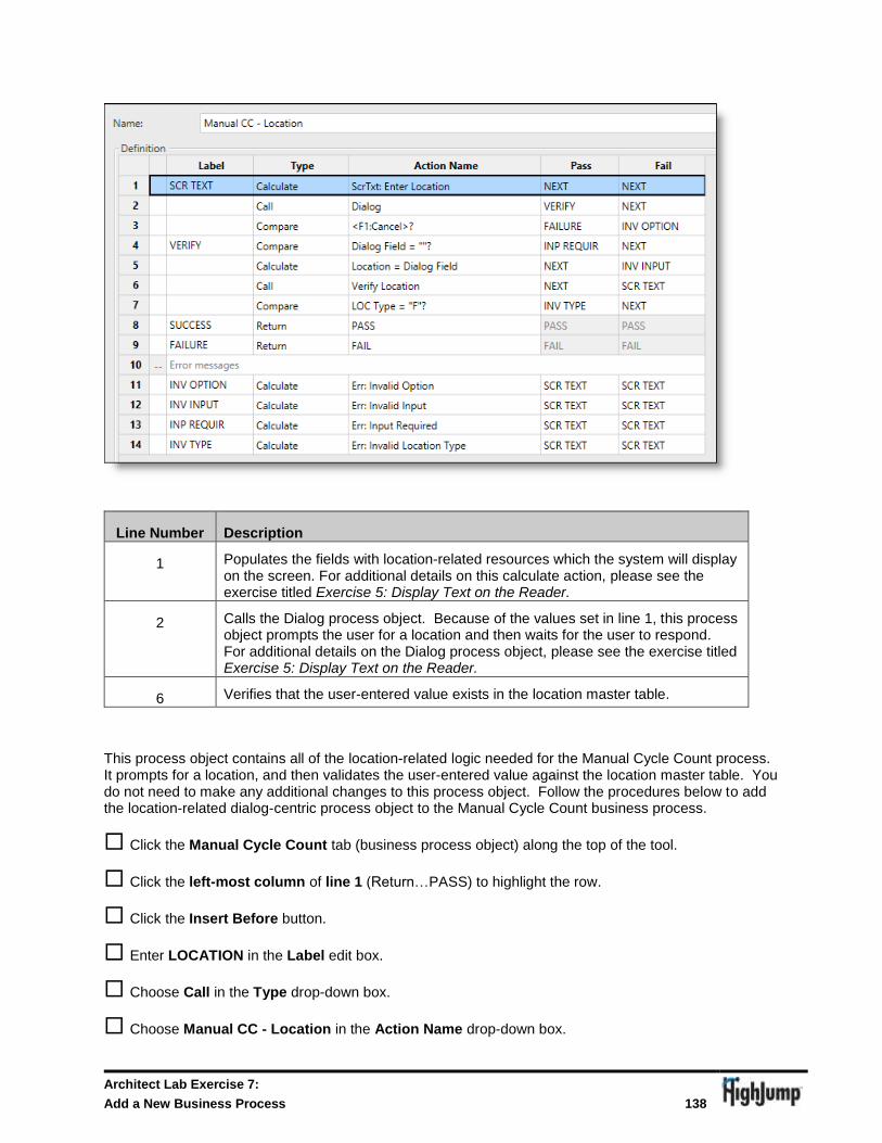
Architect Lab Exercise 7:
Add a New Business Process 138
Line Number Description
1 Populates the fields with location-related resources which the system will display on the screen. For additional details on this calculate action, please see the exercise titled Exercise 5: Display Text on the Reader.
2 Calls the Dialog process object. Because of the values set in line 1, this process object prompts the user for a location and then waits for the user to respond. For additional details on the Dialog process object, please see the exercise titled Exercise 5: Display Text on the Reader.
6 Verifies that the user-entered value exists in the location master table.
This process object contains all of the location-related logic needed for the Manual Cycle Count process. It prompts for a location, and then validates the user-entered value against the location master table. You do not need to make any additional changes to this process object. Follow the procedures below to add the location-related dialog-centric process object to the Manual Cycle Count business process.
Click the Manual Cycle Count tab (business process object) along the top of the tool.
Click the left-most column of line 1 (Return…PASS) to highlight the row.
Click the Insert Before button.
Enter LOCATION in the Label edit box.
Choose Call in the Type drop-down box.
Choose Manual CC - Location in the Action Name drop-down box.

Architect Lab Exercise 7:
Add a New Business Process 139
Choose the File | Save menu option.
The business process object looks like the following graphic.
You have accounted for the location-related dialog-centric process object. The next prompt in the Manual Cycle Count process is the Item ID. Similar to the location prompt, there are several occurrences in the Warehouse Advantage base application that prompt for an item id. Rather than build the logic from scratch, you will copy an existing item-related dialog-centric process object from another business process and then modify it for the Manual Cycle Count. Perform the following procedures to build an item-related dialog-centric process object for the Manual Cycle Count business process.
Choose the Define | Process Object menu option.
Right click the Adjust - Item node.
Choose the Copy As menu option.
The system opens the Copy As window.
Enter Manual CC – Item in the New Object Name edit box.
Click the OK button.
The system creates a new process object. The process object should look like the following graphic. The chart that follows gives a brief description of several lines.

Architect Lab Exercise 7:
Add a New Business Process 140
Line Number Description
2 Populates the fields with item-related resources which the system will display on the screen. For additional details on this calculate action, please see the exercise titled Exercise 5: Display Text on the Reader.
3 Calls the Dialog process object. Because of the values set in line 2, this process object prompts the user for an item and then waits for the user to respond. For additional details on the Dialog process object, please see the exercise titled Exercise 5: Display Text on the Reader.
7 Verifies that the user-entered value exists in the item master table.
This process object contains all of the item-related logic needed for the Manual Cycle Count process. It prompts for an item, and then validates the user-entered value against the item master table. You do not need to make any additional changes to this process object. Follow the procedures below to add the item-related dialog-centric process object to the Manual Cycle Count business process.
Click the Manual Cycle Count tab (business process object) along the top of the tool.
Click the left-most column of line 2 (Return…PASS) to highlight the row.
Click the Insert Before button.
Enter ITEM in the Label edit box.
Choose Call in the Type drop-down box.
Choose Manual CC - Item in the Action Name drop-down box.

Architect Lab Exercise 7:
Add a New Business Process 141
Choose the File | Save menu option.
The business process object looks like the following graphic.
You have accounted for the location-related dialog-centric process object and you have accounted for the item-related dialog-centric process object. The next prompt in the Manual Cycle Count process is the Quantity. Similar to the location prompt, there are several occurrences in the Warehouse Advantage base application that prompt for a quantity. Rather than build the logic from scratch, you will copy an existing quantity-related dialog-centric process object from another business process and then modify it for the Manual Cycle Count. Perform the following procedures to build a quantity-related dialog-centric process object for the Manual Cycle Count business process.
Choose the Define | Process Object menu option.
Right click the Unkwn Rcpt - Quantity node.
Choose the Copy As menu option.
The system opens the Copy As window.
Enter Manual CC – Quantity in the New Object Name edit box.
Click the OK button.
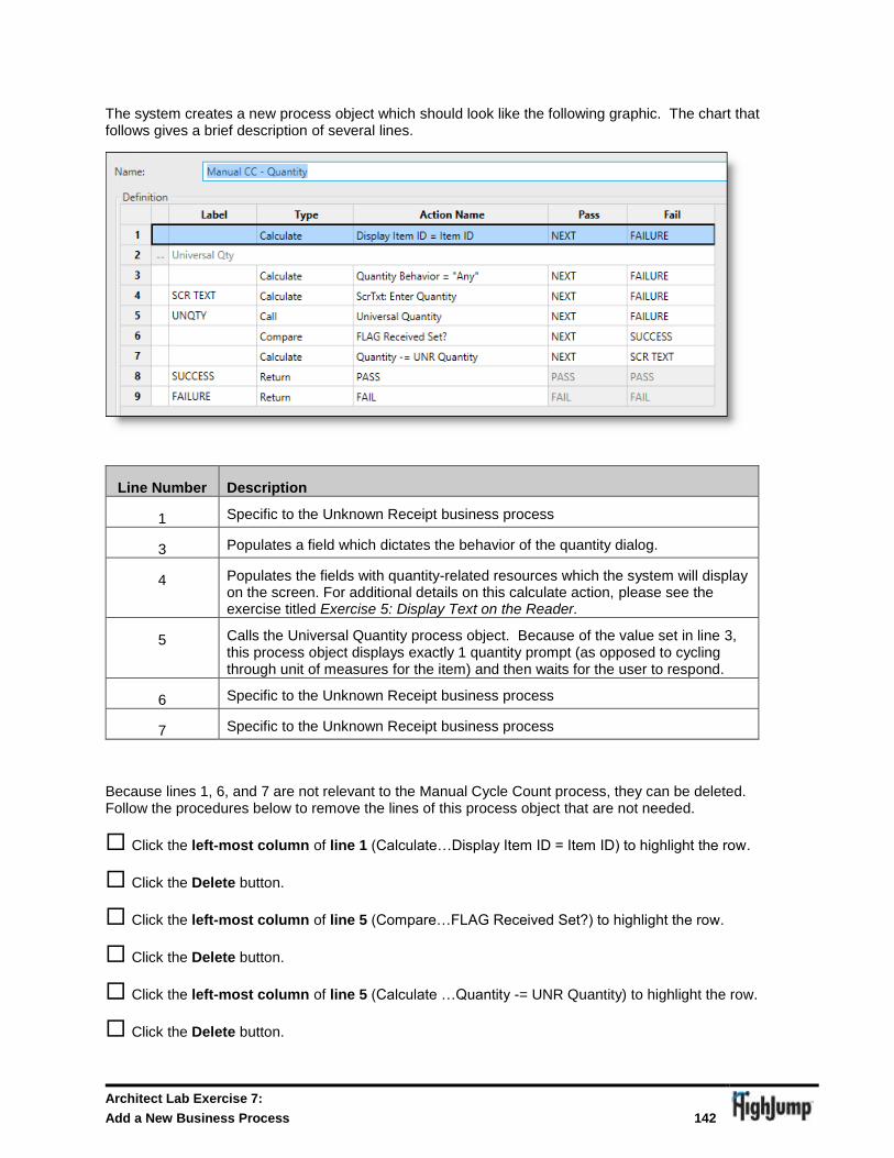
Architect Lab Exercise 7:
Add a New Business Process 142
The system creates a new process object which should look like the following graphic. The chart that follows gives a brief description of several lines.
Line Number Description
1 Specific to the Unknown Receipt business process
3 Populates a field which dictates the behavior of the quantity dialog.
4 Populates the fields with quantity-related resources which the system will display on the screen. For additional details on this calculate action, please see the exercise titled Exercise 5: Display Text on the Reader.
5 Calls the Universal Quantity process object. Because of the value set in line 3, this process object displays exactly 1 quantity prompt (as opposed to cycling through unit of measures for the item) and then waits for the user to respond.
6 Specific to the Unknown Receipt business process
7 Specific to the Unknown Receipt business process
Because lines 1, 6, and 7 are not relevant to the Manual Cycle Count process, they can be deleted. Follow the procedures below to remove the lines of this process object that are not needed.
Click the left-most column of line 1 (Calculate…Display Item ID = Item ID) to highlight the row.
Click the Delete button.
Click the left-most column of line 5 (Compare…FLAG Received Set?) to highlight the row.
Click the Delete button.
Click the left-most column of line 5 (Calculate …Quantity -= UNR Quantity) to highlight the row.
Click the Delete button.

Architect Lab Exercise 7:
Add a New Business Process 143
Choose the File | Save menu option.
The finished process object should look like the following graphic. The chart that follows gives a brief description of several lines.
Line Number Description
2 Populates a field which dictates the behavior of the quantity dialog.
3 Populates the fields with quantity-related resources which the system will display on the screen. For additional details on this calculate action, please see the exercise titled Exercise 5: Display Text on the Reader.
4 Calls the Universal Quantity process object. Because of the value set in line 3, this process object displays exactly 1 quantity prompt (as opposed to cycling through unit of measures for the item) and then waits for the user to respond.
This process object now contains all of the quantity-related logic needed for the Manual Cycle Count process. It simply prompts for a quantity, and accepts any value from the user. You do not need to make any additional changes to this process object. Follow the procedures below to add the quantity-related dialog-centric process object to the Manual Cycle Count business process.
Click the Manual Cycle Count tab (business process object) along the top of the tool.
Click the left-most column of line 3 (Return…Pass) to highlight the row.
Click the Insert Before button.
Enter QTY in the Label edit box.
Choose Call in the Type drop-down box.
Choose Manual CC - Quantity in the Action Name drop-down box.
Choose the File | Save menu option.

Architect Lab Exercise 7:
Add a New Business Process 144
The business process object should look like the following graphic.
You have accounted for all of the prompts in the Manual Cycle Count process via dialog-centric process objects. However, if you don’t do any additional development, you are left with a business process that does nothing more than capture data from the end user. In order to make this a useful business process, you need to use the captured data to update tables in the database. In a very generic sense, you need to “do work” with the data you captured from the user. The Warehouse Advantage base application uses the term “transaction” or “TX” to refer to the concept of using the captured values to update the database tables.
Before you address the transaction components of the Manual Cycle Count process, it is beneficial to look at an example. Follow the procedures below to review how another business process handles the transaction-related process objects.
Right click the Manual Cycle Count tab (business process object) along the top of the tool.
Choose the Close All But This menu option.
Choose the Define | Business Process menu option.
Double click the Location Status node.
The system opens the definition of the business process object. The chart that follows gives a brief description of several lines.
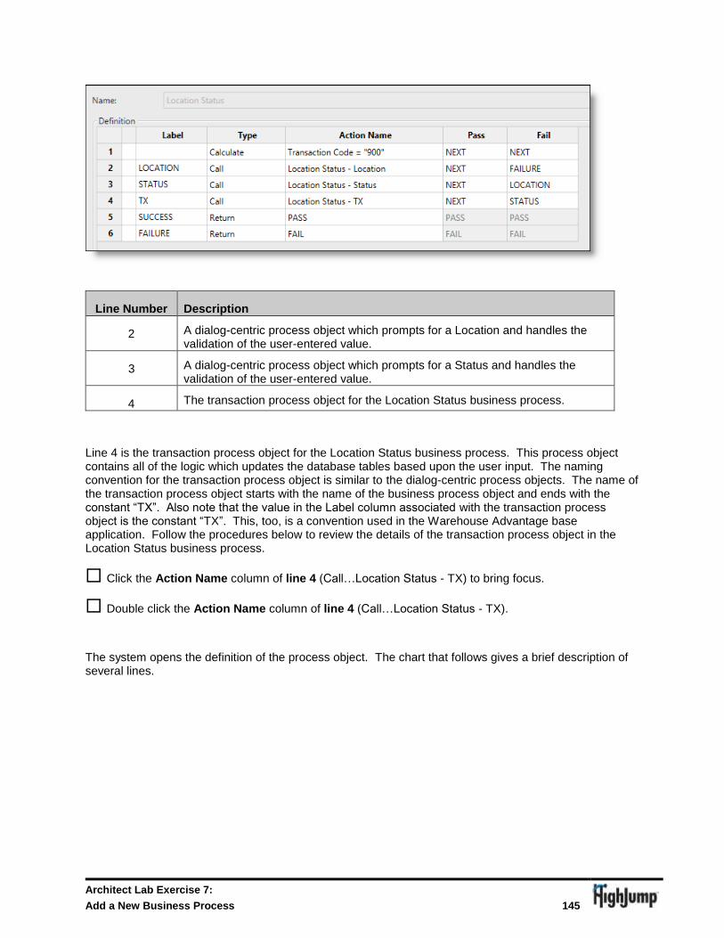
Architect Lab Exercise 7:
Add a New Business Process 145
Line Number Description
2 A dialog-centric process object which prompts for a Location and handles the validation of the user-entered value.
3 A dialog-centric process object which prompts for a Status and handles the validation of the user-entered value.
4 The transaction process object for the Location Status business process.
Line 4 is the transaction process object for the Location Status business process. This process object contains all of the logic which updates the database tables based upon the user input. The naming convention for the transaction process object is similar to the dialog-centric process objects. The name of the transaction process object starts with the name of the business process object and ends with the constant “TX”. Also note that the value in the Label column associated with the transaction process object is the constant “TX”. This, too, is a convention used in the Warehouse Advantage base application. Follow the procedures below to review the details of the transaction process object in the Location Status business process.
Click the Action Name column of line 4 (Call…Location Status - TX) to bring focus.
Double click the Action Name column of line 4 (Call…Location Status - TX).
The system opens the definition of the process object. The chart that follows gives a brief description of several lines.

Architect Lab Exercise 7:
Add a New Business Process 146
Line Number Description
2 The system uses the values supplied by the user to update the status of the location in the location master database table.
4 Writes an entry to the HighJump transaction log table.
This transaction process object consists of two components. The table update component and the log component. In the table update component, the system uses the values supplied by the user to update one or more database tables that are relevant to the business process. In the Location Status business process, the system updates the location master table. In some business processes, like Location Status, the table update component is very simple. In other business processes like Picking or Loading, where the system needs to update multiple tables, the table update component is very complex.
In the log component of the transaction process object, the system inserts a row into the HighJump transaction log table. This table contains a history of all activities that have taken place through Warehouse Advantage. If a warehouse manager needs to perform research on a given item, he can use the HighJump transaction log to review all activities associated with that item. Every entry in the HighJump transaction log is specific to a single business process and contains the important data elements for that business process. Follow the procedures below to review the details of the log component of the Location Status business process.
Click the Action Name column of line 4 (Call…Log – Location Status) to bring focus.
Double click the Action Name column of line 4 (Call…Log - Location Status).
The system opens the definition of the process object. The chart that follows gives a brief description of several lines.

Architect Lab Exercise 7:
Add a New Business Process 147
Line Number Description
1 – 10 The system builds and appends a record to an Advantage Architect list. Line 9 accounts for the data elements that are specific to the Location Status business process.
13 Calls the Log TX process object which inserts the data into the HighJump transaction log.
This process object consists of two parts. The first part (lines 1 – 10) builds and appends a record to an Advantage Architect list. Each record in the list contains all of the data elements for exactly one row in the HighJump transaction log. In the Location Status business process, the system only needs to insert one record into the HighJump transaction log. Consequently, this logic is relatively simple. In other business processes, like Move, the system may need to insert multiple rows into the HighJump transaction log. In these cases, the logic can be quite complex.
The second part of this process object (line 13) calls the base application process object Log TX. The Log TX process object loops through the Advantage Architect list built in the first 10 lines. For each record in the list, it inserts one row into the HighJump transaction log. It also conditionally sends a transaction to the host. Log TX is a generic base application process object that is used in all business processes that need to insert rows into the HighJump transaction log.
Since every row in in the HighJump transaction log is specific to a single business process, the logic must account for differences between the business processes. For example, the Order Picking business process needs to store the order number in the log, but the Location Status business process does not utilize order numbers. Follow the procedures below to review the details of the calculate action that accounts for the data elements of the log that are specific to the Location Status business process.
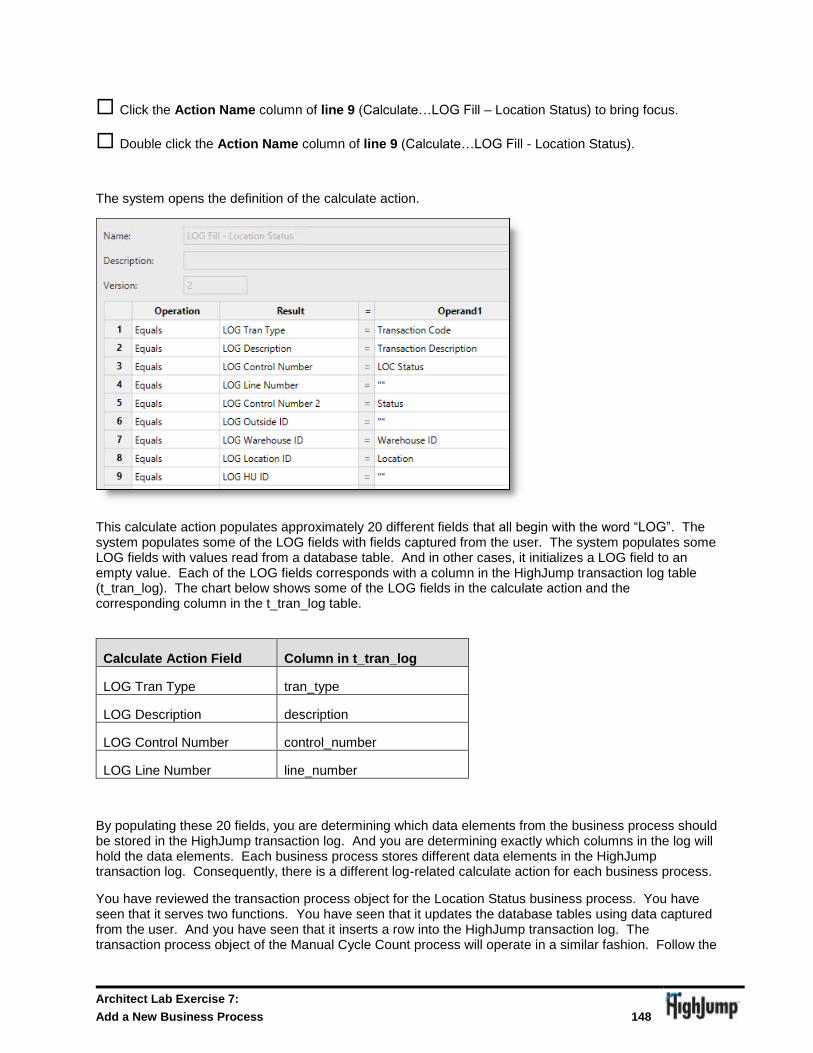
Architect Lab Exercise 7:
Add a New Business Process 148
Click the Action Name column of line 9 (Calculate…LOG Fill – Location Status) to bring focus.
Double click the Action Name column of line 9 (Calculate…LOG Fill - Location Status).
The system opens the definition of the calculate action.
This calculate action populates approximately 20 different fields that all begin with the word “LOG”. The system populates some of the LOG fields with fields captured from the user. The system populates some LOG fields with values read from a database table. And in other cases, it initializes a LOG field to an empty value. Each of the LOG fields corresponds with a column in the HighJump transaction log table (t_tran_log). The chart below shows some of the LOG fields in the calculate action and the corresponding column in the t_tran_log table.
Calculate Action Field Column in t_tran_log
LOG Tran Type tran_type
LOG Description description
LOG Control Number control_number
LOG Line Number line_number
By populating these 20 fields, you are determining which data elements from the business process should be stored in the HighJump transaction log. And you are determining exactly which columns in the log will hold the data elements. Each business process stores different data elements in the HighJump transaction log. Consequently, there is a different log-related calculate action for each business process.
You have reviewed the transaction process object for the Location Status business process. You have seen that it serves two functions. You have seen that it updates the database tables using data captured from the user. And you have seen that it inserts a row into the HighJump transaction log. The transaction process object of the Manual Cycle Count process will operate in a similar fashion. Follow the

Architect Lab Exercise 7:
Add a New Business Process 149
procedures below to create a process object shell that will eventually serve as the transaction process object for the Manual Cycle Count business process.
Choose the View | Close All menu option.
Choose the Define | Process Object menu option.
Choose the File | New menu option.
Enter Manual CC - TX in the Name edit box.
Click the Properties button to collapse the header information.
Choose the File | Save menu option.
At this point, you have a basic process object from to which you can add additional actions.
One of the functions of the transaction process object is to update the database tables based upon data captured from the user. In the case of the Manual Cycle Count business process it would make sense to update the inventory table with the quantity entered by user. It would also make sense to update the location master table with the date/time that the user counted the location. However, as stated above, the Manual Cycle Count business process that you are building is a simplistic process that is not production ready. Rather than add logic to update the inventory table and to update the location master table, you will add a placeholder for these items in the transaction process object. In this instance, you will add a comment indicating where these tables should be updated. Follow the procedures below to insert a comment into the Manual Cycle Count transaction process object.
Click the left-most column of line 1 (Return…PASS) to highlight the line.
Click the Insert Before button.
Double click the second column from the left to create a comment.
Enter Update the inventory table and the location master table in the comment edit box.
Click the Insert After button.
Double click the second column from the left to create a comment.
Choose the File | Save menu option.

Architect Lab Exercise 7:
Add a New Business Process 150
The resulting process object should look like the following graphic.
The second function of the transaction process object is to insert a row into the HighJump transaction log. Rather than build this logic from scratch, you will copy existing log-related objects from another business process and then modify them for Manual Cycle Count. Perform the following procedures to create log-related process object for the Manual Cycle Count business process.
Choose the Define | Process Object menu option.
Right click the Log – Location Status node.
Choose the Copy As menu option.
The system displays the Copy As window.
Enter Log – Manual Cycle Count in the New Object Name edit box.
Click the OK button.
The system creates a new process object that should look like the following graphic. The chart that follows gives a brief description of several lines.

Architect Lab Exercise 7:
Add a New Business Process 151
Line Number Description
1 – 10 The system builds and appends a record to an Advantage Architect list. Line 9 accounts for the data elements that are specific to the Location Status business process. You will modify line 9 later in this exercise.
13 Calls the Log TX process object which inserts the records from the list into the HighJump transaction log.
This log process object was created from the log process object in the Location Status business process. It is a very generic process object. Line 9 is the only line that contains logic specific to the Location Status business process. Line 9 currently populates the LOG fields with the data elements from the Location Status business process that need to be stored in the HighJump transaction log. You need to replace line 9 with a calculate action that populates the LOG fields with the data elements from the Manual Cycle Count business process. Like before, rather than building the new calculate action from scratch, you will copy a similar calculate action from another business process and then modify it for Manual Cycle Count. Perform the following procedures to create a log-related calculate action for the Manual Cycle Count business process.
Click the Action Name column of line 9 (calculate…LOG Fill – Location Status) to bring focus.
Double click the Action Name column of line 9 (calculate…LOG Fill – Location Status).
Choose the File – Copy As menu option.

Architect Lab Exercise 7:
Add a New Business Process 152
The system opens the Copy As window.
Enter LOG Fill – Manual Cycle Count in the New Object Name edit box.
Click the OK button.
The process object should look like the following graphic.
This log fill calculate action was created from the log fill calculate action in the Location Status business process. It currently populates the LOG fields with data elements from the Location Status business process. You need to modify this calculate action so that the LOG fields are populated with data elements from the Manual Cycle Count business process.
Earlier in this exercise you added dialog-centric process objects to the Manual Cycle Count business process that captured a location, an item id, and a quantity from the user. These are the three data elements that you need to add to the HighJump transaction log for Manual Cycle Count. Consequently, you need to account for the same three data elements in the log fill calculate action. Many of the other LOG fields in the calculate action can be initialized to empty values. Follow the procedures below to ensure the system writes the location, item id, and quantity data elements from the Manual Cycle Count business process to the HighJump transaction log.
Click the Operand1 cell of line 3 (Log Control Number = LOC Status) to bring focus.
Click the Asterisk button on the right side of the Operand 1 drop down box.

Architect Lab Exercise 7:
Add a New Business Process 153
Chose the Constant - String menu option.
Choose the File | Save menu option.
The calculate action should look like the following graphic.
Click the Operand1 cell of line 5 (Log Control Number 2 = Status) to bring focus.
Click the Asterisk button on the right side of the Operand 1 drop down box.
Chose the Constant - String menu option.
Choose the File | Save menu option.
The calculate action should look like the following graphic.
Click the Operand1 cell of line 11 (Log Item ID = “”) to bring focus.
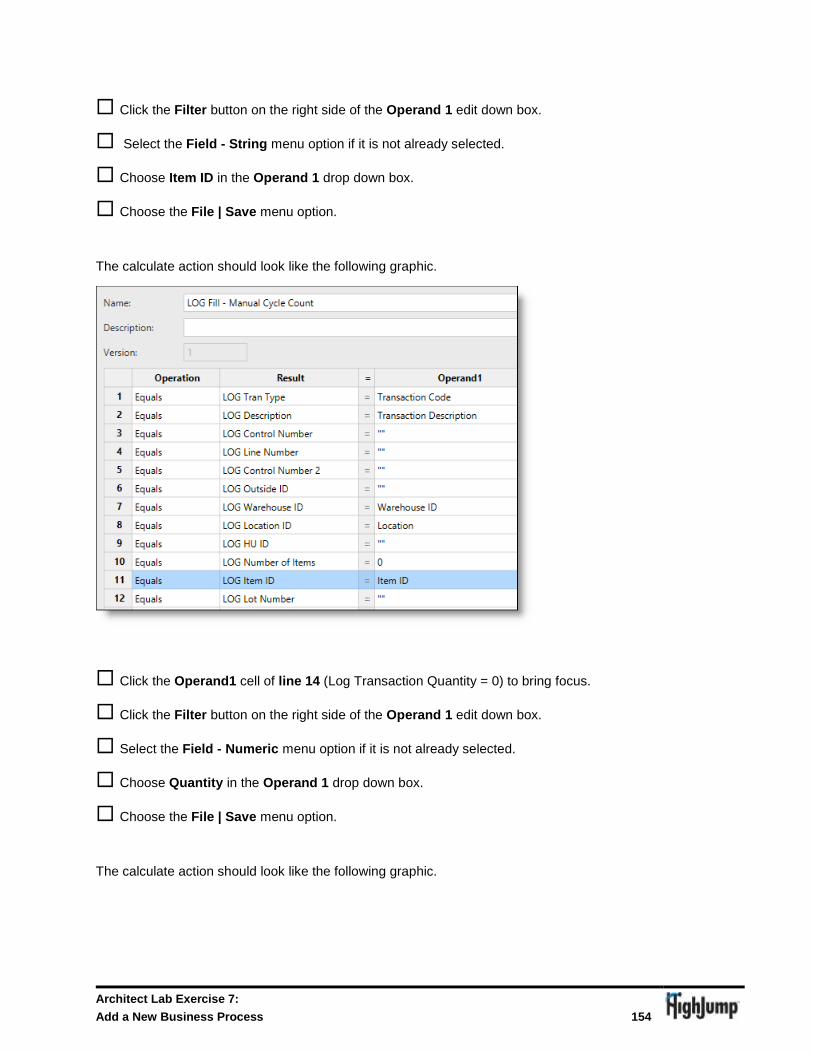
Architect Lab Exercise 7:
Add a New Business Process 154
Click the Filter button on the right side of the Operand 1 edit down box.
Select the Field - String menu option if it is not already selected.
Choose Item ID in the Operand 1 drop down box.
Choose the File | Save menu option.
The calculate action should look like the following graphic.
Click the Operand1 cell of line 14 (Log Transaction Quantity = 0) to bring focus.
Click the Filter button on the right side of the Operand 1 edit down box.
Select the Field - Numeric menu option if it is not already selected.
Choose Quantity in the Operand 1 drop down box.
Choose the File | Save menu option.
The calculate action should look like the following graphic.

Architect Lab Exercise 7:
Add a New Business Process 155
You have built a log calculate action that populates the LOG fields with data elements from the Manual Cycle Count business process. The system will take these LOG fields and eventually write them to HighJump transaction log. However, the development is not complete. This calculate action is an orphaned object. There are no process objects in the application that execute the calculate action. In order to utilize this log calculate action you must add it to the log process object that handles all log-related logic in the Manual Cycle Count business process. Follow the procedures below to add the log calculate action to the log process object for Manual Cycle Count.
Click the Log – Manual Cycle Count tab (process object) along the top of the tool.
Click the left-most column of line 9 (calculate…LOG – Fill Location Status) to highlight the row.
Choose LOG Fill – Manual Cycle Count in the Action Name drop down box.
Choose the File | Save menu option.
At this point, all of the Location Status logic in this log process object has been replaced with Manual Cycle Count logic. The final process object should look like the following graphic. The chart that follows gives a brief description of several lines.

Architect Lab Exercise 7:
Add a New Business Process 156
Line Number Description
1 – 10 The system builds and appends a record to an Advantage Architect list. Line 9 populates the LOG fields with the data elements specific to the Manual Cycle Count business process.
13 Calls the Log TX process object which inserts the records from the list into the HighJump transaction log.
You have built a log process object that handles all of the log-related logic for the Manual Cycle Count business process. However, the development is not complete. This log process object is an orphaned object. There are no process objects in the application that call the log process object. In order to utilize this log process object you must add it to the transaction process object for Manual Cycle Count. Follow the procedures below to add the log process object to the transaction process object for Manual Cycle Count.
Click the Manual CC - TX tab (process object) along the top of the tool.
Click the left-most column of line 3 (Return…PASS) to highlight the line.
Click the Insert Before button.
Enter LOG in the Label edit box.
Choose Call in the Type drop-down box.

Architect Lab Exercise 7:
Add a New Business Process 157
Choose Log – Manual Cycle Count in the Action Name drop-down box.
Choose FAILURE in the Fail drop down box.
Click the left-most column of line 4 (Return…Pass) to highlight the line.
Click the Insert Before button.
Double click the second column from the left to create a comment.
Choose the File | Save menu option.
The final process object should look like the following graphic. The chart that follows gives a brief description of several lines.
Line Number Description
1 A comment which serves as a place holder where the system would update the tables based upon the data captured from the user.
3 Inserts a Manual Cycle Count record into the HighJump transaction log.
You have built a transaction process object that accounts for the updates to the database tables and also accounts for the HighJump transaction log. However, the development is not complete. This transaction process object is an orphaned object. There are no process objects in the application that call the transaction process object. In order to utilize this transaction process object you must add it to the top-level business process object for Manual Cycle Count. Follow the procedures below to add the transaction process object to the business process object for Manual Cycle Count.
Choose the Define | Business Process menu option.
Double click the Manual Cycle Count node.
Click the left-most column of line 4 (Return…PASS) to highlight the line.

Architect Lab Exercise 7:
Add a New Business Process 158
Click the Insert Before button.
Double click the second column from the left to create a comment.
Click the left-most column of line 5 (Return…PASS) to highlight the line.
Click the Insert Before button.
Enter TX in the Label edit box.
Choose Call in the Type drop-down box.
Choose Manual CC – TX in the Action Name drop-down box.
Choose QTY in the Fail drop down box.
Click the left-most column of line 6 (Return…PASS) to highlight the line.
Click the Insert Before button.
Double click the second column from the left to create a comment.
Choose the File | Save menu option.
The business process object should look like the following graphic. The chart that follows gives a brief description of several lines.
Line Number Description
1 – 3 Prompt for a Location, an Item ID, and a Quantity.
5 Update the database tables based upon the user-entered values. Additionally, insert a record into the HighJump transaction log.

Architect Lab Exercise 7:
Add a New Business Process 159
You have added the dialog-centric process objects to the Manual Cycle Count business process object, and you have added the transaction process object to the Manual Cycle Count business process object. However, there is one more screen that the system should display to the user. When the system finishes updating the database tables and writing the record to the HighJump transaction log, the system should give a visual indication to the user that they have successfully completed one iteration of Manual Cycle Count. At the end of each iteration, the system should display the text “Transaction Complete” to the user. Follow the procedures below to display the Transaction Complete screen to the user at the end of each iteration.
Click the left-most column of line 7 (Return…PASS) to highlight the line.
Click the Insert Before button.
Choose Call in the Type drop-down box.
Choose Transaction Complete in the Action Name drop-down box.
Click the left-most column of line 8 (Return…PASS) to highlight the line.
Click the Insert Before button.
Double click the second column from the left to create a comment.
Choose the File | Save menu option.
The business process object should look like the following graphic. The chart that follows gives a brief description of several lines.

Architect Lab Exercise 7:
Add a New Business Process 160
Line Number Description
1 – 3 Prompt for a Location, an Item ID, and a Quantity.
5 Update the database tables based upon the user-entered values. Additionally, insert a record into the HighJump transaction log.
7 Display the Transaction Complete screen to the user.
You have added the dialog-centric process objects to the Manual Cycle Count business process object. You have added the transaction process object to the Manual Cycle Count business process object. And you have added the Transaction Complete screen. However, there is still a missing element. All business process objects have a 3-digit numeric identifier that uniquely identifies the business process. This numeric identifier is called a transaction code.
The transaction code for Order Picking is 301. The one for Physical Inventory is 880. All transaction codes are documented on the HighJump Documentation Site in an Excel file called WA Log Transactions. The system includes the transaction code when it writes a record to the HighJump transaction log. It also uses the transaction code in shared process objects when it needs to branch to different line numbers for different business processes. Follow the procedures below to review an example of how the Location Status business process accounts for the transaction code.
Choose the Define | Business Process menu option.
Double click the Location Status node.
The system opens the definition of the business process object.
Line number 1 of the business process object contains the logic that establishes the transaction code value. Most business process objects determine the transaction code near the top.
Click the Action Name column of line 1 (Calculate…Transaction Code = “900”) to bring focus.
Double click the Action Name column of line 1 (Calculate… Transaction Code = “900”).

Architect Lab Exercise 7:
Add a New Business Process 161
The system opens the definition of the calculate action.
This calculate action populates two fields. The Transaction Code field is the unique identifier. The Transaction Description is the name of the business process. The system includes both fields when it inserts a record into the HighJump transaction log. Virtually all calculate actions of this nature populate the same two fields. Rather than building a new calculate action from scratch for the Manual Cycle Count business process, you will copy this one and then modify it for Manual Cycle Count. If you were to read the Excel file which documents the transaction codes, you would see that transaction code 891 is not used in the base application. Perform the following procedures to build a calculate action that establishes the transaction code (891) and the transaction description for the Manual Cycle Count business process.
Right click the Transaction Code = “900” tab along the top.
Choose the Copy As menu option.
The system displays the Copy As window.
Enter Transaction Code = “891” in the New Object Name edit box.
Click the OK button.
The system creates a new calculate action that looks like the following graphic.

Architect Lab Exercise 7:
Add a New Business Process 162
Click the Operand1 cell of line 1 (Transaction Code = 900) to bring focus.
Enter 891 in the Operand 1 edit box.
Click the Operand1 cell of line 2 (Transaction Description = Location Status) to bring focus.
Enter Manual Cycle Count in the Operand 1 edit box.
Choose the File | Save menu option.
The finished calculate action should look like the following graphic.
You have built a calculate action that establishes the transaction code for the Manual Cycle Count business process. However, this calculate action is an orphaned object. There are no process objects which call it. In order to leverage its functionality, you must include it in the business process object for Manual Cycle Count. Perform the procedures below to add the transaction code calculate action to the Manual Cycle Count business process object.
Click the Manual Cycle Count tab (business process object) along the top of the tool.
Click the left-most column of line 1 (Call…Manual CC - Location) to highlight the line.
Click the Insert Before button.
Choose Calculate in the Type drop-down box.

Architect Lab Exercise 7:
Add a New Business Process 163
Choose Transaction Code = “891” in the Action Name drop-down box.
Click the Insert After button.
Double click the second column from the left to create a comment.
Choose the File | Save menu option.
The business process object should look like the following graphic. The chart that follows gives a brief description of several lines.
Line Number Description
1 Establishes the transaction code
3 – 5 Prompt for a Location, an Item ID, and a Quantity.
7 Update the database tables based upon the user-entered values. Additionally, insert a record into the HighJump transaction log.
9 Display the Transaction Complete screen to the user.
You have established the transaction code. You have accounted for three prompts and the transaction complete screen. And you have built and added the transaction process object. However, there is a final change that you need to make to the business process object. As a general rule, in the Warehouse Advantage base application, when you press the F1 key at a prompt on the RF terminal, the system navigates backwards to the previous prompt. This logic is absent from the Manual Cycle Count business process. If you follow the development standards, the dialog-centric process objects will generally return

Architect Lab Exercise 7:
Add a New Business Process 164
FAIL if the user presses the F1 key at a prompt. Consequently, if you want to navigate backwards in the prompting sequence, you need to modify the FAIL branch on each dialog-centric process object in the business process object. The reasoning behind this behavior will be explained in a later exercise. Follow the procedures below to navigate backwards in the prompting sequence when the user presses the F1 key in the Manual Cycle Count process.
Right click the Manual Cycle Count tab (business process object) along the top of the tool.
Choose the Close All But This menu option.
Click the left-most column of line 5 (Call…Manual CC - Quantity) to highlight the line.
Choose ITEM in the Fail drop down box.
Click the left-most column of line 4 (Call…Manual CC - Item) to highlight the line.
Choose LOCATION in the Fail drop down box.
Click the left-most column of line 3 (Call…Manual CC - Location) to highlight the line.
Choose FAILURE in the Fail drop down box.
Choose the File | Save menu option.
The final business process object should look like the following graphic. The chart that follows gives a brief description of several lines.
Line Number Description

Architect Lab Exercise 7:
Add a New Business Process 165
1 Establishes the transaction code
3 – 5 Prompt for a Location, an Item ID, and a Quantity.
7 Update the database tables based upon the user-entered values. Additionally, insert a record into the HighJump transaction log.
9 Display the Transaction Complete screen to the user.
At this point you have added all of the necessary components to the Manual Cycle Count business process object in Advantage Architect. In its relatively simplistic form, it will meet the needs of the warehouse manager. However, even if you were to audit and activate the application you would not be able to execute the Manual Cycle Count business process on the RF terminal. In order to run the business process on the terminal, you must first create a new menu option for the RF terminal and then associate the business process object with the menu option. Follow the procedures below to add the Manual Cycle Count process to a menu on the RF terminal.
Open Microsoft SQL Server Management Studio. (For additional details, please see the activity titled Develop the Changes in exercise Exercise 4: Calculate Actions of this manual.)
Choose the File | Open | File menu.
Click the Desktop button on the left panel.
Navigate to the Training \ Architect \ SQL folder.
Click the insert_t_menu_cycle_count.sql file.
Click the Open button.
The system opens the file in a new tab.
Choose the Query | Execute menu.
The system inserts a row into the t_menu table and then displays a subset of rows from the t_menu table. The chart that follows gives a brief description of several columns from the table.

Architect Lab Exercise 7:
Add a New Business Process 166
Column Name
Description
locale_id Numeric value indicating the language. 1033 is English.
menu_level A menu level is a collection of menu options that appear on the RF terminal. By using multiple menu levels you can restrict access to certain processes on a per user basis.
name The name of the submenu. In this case, the four menu options appear on a cycle count submenu.
sequence The order in which the system displays the menu options.
text The text that the system displays on the terminal.
process The name of the business process object that the system initiates when the user chooses that particular menu option.
The link between the t_menu database table and the objects in Advantage Architect is the column titled “process”. In the example above, when the user selects option 4 from the cycle count submenu, the system initiates the business process object called Manual Cycle Count.
You have built the Manual Cycle Count business process object. And you have associated it with a menu option on the RF terminal. The development process is now complete.
Activity 4: Compile and Activate the Changes
At this point you have modified several objects to meet the requirements dictated by the warehouse manager. However, if you view the Virtual Terminal, you will see that the changes have had no impact. In order to see the changes reflected on the Virtual Terminal, you must first compile the application and then activate the application. The procedures below are very generic. If you need additional details on how to compile and activate the application, please see the activity titled Compile and Activate the Changes in Exercise 1 of this manual.
Compile the application
Activate the application

Architect Lab Exercise 7:
Add a New Business Process 167
Activity 5: Test the Changes
The chart below outlines the various test cases that must be validated. Each test case defines an action you must take, and it defines the expected outcome based on the requirements. If a given test case does not yield the expected outcome, then review the steps from the previous activity. It is likely that you either missed a step or performed a step incorrectly. The test cases do not detail every keystroke. You need to use the knowledge you gained in the first activity of this exercise in order to test the scenarios.
Starting the Manual Cycle Count Business Process
From the Main Menu choose F8, Option 7
Test Case Expected Outcome Pass / Fail
Choose option 2 (the Cycle Counts menu) on the RF.
System displays four cycle counting related menu options. The fourth option is Manual Cycle Cnt.
Choose option 4 (the Manual Cycle Cnt menu)
System displays the Location dialog.

Architect Lab Exercise 7:
Add a New Business Process 168
Enter a valid location (M101 and M102 are both valid) at the location dialog.
System displays the Item Number dialog.
Enter a valid item number (NNFG00000 is one) at the item number dialog.
System displays the Quantity dialog.
Enter a quantity at the quantity dialog.
a) System displays the Transaction Complete dialog.
a) Open SQL Server Management Studio
The system displays the Manual Cycle Count transaction from the HighJump transaction log. The location_id,

Architect Lab Exercise 7:
Add a New Business Process 169
b) Choose the File | Open | File menu.
c) Click the Desktop button on the left panel.
d) Navigate to the Training \ Architect \ SQL folder.
e) Click the select_tran_log_manual_ cycle_count.sql file.
f) Click the Open button.
g) Choose the Query | Execute menu.
item_number, and the tran_qty columns hold the values you entered on the RF terminal.
Hit the Enter Key on the Transaction Complete dialog.
System displays the Location dialog.
Repeat Manual Cycle Count and choose the F1 key at the Quantity dialog.
System displays the Item Number dialog.
Repeat Manual Cycle Count and choose the F1 key at the Item Number dialog.
System displays the Location dialog.

Architect Lab Exercise 7:
Add a New Business Process 170
Repeat Manual Cycle Count and choose the F1 key at the Location dialog.
System displays the menu dialog.
Activity 6: Check in the Objects
Earlier in this exercise, you checked out several objects and made changes to them. As long as the objects are checked out in your name, you are the only developer who can alter their definitions. Because your changes met the warehouse manager’s requirements, you can make the objects available to other Architect developers in your company. In the steps below, you will check in the objects so that other developers can make additional changes to them.
Choose the View | Close All menu option.
Check in all of the objects.

Architect Lab Exercise 8:
Add a Database Column 171
Architect Lab Exercise 8: Add a Database Column
Introduction
In this exercise you will add a column to the PO master table which indicates whether or not a purchase order has passed through the Unload Inbound Order business process. Then you will add rules to the Unload Inbound Order business process and the Receipt from Vendor business process which require all purchase orders to be unloaded before they are received.
Background Information This exercise uses the Unload Inbound Order business process and the Receipt from Vendor business process as a basis for all activities. The Unload Inbound Order business process records the arrival of an inbound order into the warehouse. However, this process does not receive any inventory into the warehouse. It only indicates that an inbound order has appeared at an inbound door.
The Receipt from Vendor process allows the user to receive inventory against a purchase order. The user builds the inventory on his fork. When his fork is full, he presses the F3:Done function key, and then the system directs the user to move the inventory into the storage racks.
This exercise emphasizes the topic of database actions. It also utilizes the concept of a record which you reviewed in a previous lesson. The following online lessons give an introduction to database actions and also provide an opportunity to take a second look at the online material for records.
1. Open the Advantage Architect online course.
2. Review the Create Database Action topic.

Architect Lab Exercise 8:
Add a Database Column 172
Activity 1: Understand the Current Process
This activity demonstrates the Unload Inbound Order business process and the Receipt of Inbound Order business process on the RF terminal. Follow the procedures below to see how the Unload Inbound Order process operates in the base application.
Log in to the Virtual Terminal as AMY / AMY / FAAMY.
Enter option 1 (the Receipts menu.)
Enter option 1 (the Unload Inbd Order menu.)
Enter PO2 at the PO Number dialog.
Press the Enter Key at the Carrier Name dialog.
Enter any number displayed on the list at the Carrier Name List dialog.
Enter S2 at the Location dialog.
Enter 10 at the Quantity dialog.
If the system bypasses the Quantity prompt then retry the process with a different Purchase Order number. PO1, PO2, PO3, PO4, and PO5 are all valid purchase orders. If the system still bypasses the Quantity prompt, then open SQL Server Management Studio and run the reset_pos.sql script in the TRAINING \ ARCHITECT \ SQL folder on the desktop. If you have any difficulties, then please contact an instructor.
Press the Enter key at the Transaction Complete dialog.
Press the F1 key to return to the Receipts menu.
Follow the procedures below to see how the Inbound Order Receipt process operates in the base application.
Enter option 3 (the Vendor Receipts menu.)
Enter option 1 (the Inbound Order Rcp menu.)
If the system displays a dialog showing multiple function key options, then press the F5:New function key to create a new receipt ID.
Press the Enter key at the Receipt ID dialog to select the default value.
Type PO2 at the PO Number dialog.
The system continues with the Carrier Name dialog. There are several more dialogs in this process. However, the only dialog that is relevant to this activity is the PO Number dialog. Follow the procedures below to exit the business process.

Architect Lab Exercise 8:
Add a Database Column 173
Press the F1 key at the Carrier Name dialog.
Press the F1 key at the PO Number dialog.
Enter Y at the Are you sure dialog.

Architect Lab Exercise 8:
Add a Database Column 174
Activity 2: Understand the Requirements
This activity identifies the changes that the warehouse manager wants to make to the Unload Inbound Order business process and the Inbound Order Receipt business process.
The warehouse manager calls you on the phone. He explains that the users can execute the Inbound Order Receipt process with a PO that has not passed through the Unload Inbound Order process. This does not cause any corrupt data. However, procedurally, he wants all purchase orders to first pass through the Unload Inbound Order process.
The two of you discuss a couple possibilities. In the end you agree that adding behind-the-scenes database updates and database validations is the best way to force the unload before the receipt.
Activity 3: Develop the Changes (Phase 1)
In order to meet the warehouse manager’s requirements you must change two business processes: Unload Inbound Order and Inbound Order Receipt. In this exercise, you will build and test the changes in two phases. In Phase 1, you will build and test the changes specific to the Unload Inbound Order business process. Then in Phase 2, you will build and test the changes specific to the Inbound Order Receipt business process.
There are a couple ways to meet the warehouse manager’s requirements. After a bit of deliberation, you decide that the best approach is to add a column to the PO master table. This column will hold a flag that indicates whether or not the PO has passed through the Unload Inbound Order process. The flag will be initialized to N, and the Unload Inbound Order process will update it to Y. Then the Inbound Order Receipt process will validate that the flag is set to Y before allowing the user to continue.
At the core of this solution is the new column in the PO master database table. Follow the procedures below to add the unload_flag column to the t_po_master table.
Open Microsoft SQL Server Management Studio. (For additional details, please see the activity titled Develop the Changes in exercise Exercise 4: Calculate Actions of this manual.)
Choose the File | Open | File menu.
Click the Desktop button on the left panel.
Navigate to the Training \ Architect \ SQL folder.
Click the alter_t_po_master.sql file.
Click the Open button.
The system opens the file in a new tab.

Architect Lab Exercise 8:
Add a Database Column 175
Choose the Query | Execute menu.
The system adds the unload_flag column to the t_po_master table. Then it selects a subset of data from the table. The graphic below shows the subset of data and a brief description of each column.
Column Name
Description
po_number The purchase order.
wh_id The warehouse ID
unload_flag A Y / N flag that indicates whether or not the purchase order has passed through the Unload Inbound Order process.
You have made the changes to the database. Next you will make changes in Advantage Architect to utilize the new column in the database. However, before you make any changes in Architect, it is important to understand some of the underlying principles used to interact with the database. Follow the procedure below to review an example of how the base application builds and sends queries to the database.
In Advantage Architect, double click WA in the Repository tab.
Choose the Define | Business Process menu option.
Double click the Location Status node.
The system opens the definition of the business process object. The chart that follows gives a brief description of several lines.

Architect Lab Exercise 8:
Add a Database Column 176
Line Number Description
2 A dialog-centric process object which prompts for a Location and handles the validation of the user-entered value.
3 A dialog-centric process object which prompts for a Status and handles the validation of the user-entered value.
4 The transaction process object for the Location Status business process.
The purpose of the Location Status business process is to allow a user to the change the status of a location. The system captures the location and the new status from the end user. Then the system uses that information to update the status column of the t_location table. Since the update occurs at the end of the business process, you would expect to find the update logic buried within the transaction process object for Location Status. For additional details on transaction process objects, please see the activity titled Develop the Changes in exercise Exercise 7: Add a New Business Process of this manual. Follow the procedures below review the transaction process object for Location Status.
Click the Action Name column of line 4 (Call…Location Status - TX) to bring focus.
Double click the Action Name column of line 4 (Call…Location Status - TX).
The system opens the definition of the process object. The chart that follows gives a brief description of several lines.

Architect Lab Exercise 8:
Add a Database Column 177
Line Number Description
2 The system uses the values supplied by the user to update the status of the location in the location master database table.
4 Writes an entry to the HighJump transaction log table.
Because this transaction process object updates the location master table, you might expect to see a database action in it. However, the transaction process object only contains two call actions and two return actions. The logic which updates the location master table is buried within line 2. Line 2 is called a database wrapper process object.
The development conventions indicate that every database action should be wrapped in a process object which is solely dedicated to supporting that single database action. That process object is called a database wrapper process object. The conventions also indicate that the name of the database wrapper process object should begin with the characters “DB”. Follow the procedures below to review the details of the database wrapper process object which updates the status of a given location.
Click the Action Name column of line 2 (Call…DBUpd LOC Status w/Loc,<>Sts) to bring focus.
Double click the Action Name column of line 2 (Call…DBUpd LOC Status w/Loc,<>Sts).
The system opens the definition of the database wrapper process object. The chart that follows gives a brief description of several lines.

Architect Lab Exercise 8:
Add a Database Column 178
Line Number Description
1 – 2 Validate that the Location field and the Status field have values. If either field does not have a value, then continue with line 7.
3 Build and send a database query to the database server. The query updates the status column of the t_location table. This line is at the core of database wrapper process object.
4 – 5 Handles the case when the database action fails.
7 Build an error message, which the system will eventually display to the user.
8 – 9 Build a log message and send the message to the HighJump platform log.
Line 3 is the database action which updates the status of the location master table. This database action is at the heart of the process object. Every line in the database wrapper process object supports line 3 in some manner. Follow the procedures below to review the details of the database action.
Click the Action Name column of line 3 (Database…Upd LOC Status w/Loc,<>Sts) to bring focus.
Double click the Action Name column of line 3 (Database…Upd LOC Status w/Loc,<>Sts).
The system opens the definition of the database action.

Architect Lab Exercise 8:
Add a Database Column 179
The SQL query is a combination of HighJump syntax and standard SQL syntax. The STATEMENT / RETURNS syntax is HighJump syntax. It is used to separate the source query from how the HighJump system handles the result set (if any) from the database server. The elements enclosed in colons (also color-coded in red) are Advantage Architect fields. At runtime, the system rebuilds the query by replacing the colon-enclosed elements in the STATEMENT clause with the value of the fields from memory. Then it sends the rebuilt query to the database server for processing. If the database server returns any data (as in a SELECT query), the HighJump system would then process the results. The query below is one example of how the system rebuilds the query based upon the value of Advantage Architect fields.
UPDATE t_location
SET status = 'I'
WHERE status <> 'I'
AND location_id = 'M101'
AND wh_id = '01'
You have seen how the base application wraps database actions in a process object completely dedicated to that database action. And you have seen that the database actions contain both HighJump syntax and standard SQL syntax. Now you will apply this knowledge to the Unload Inbound Order process. In the Unload Inbound Order process you need to update the unload_flag column to N in the t_po_master table for a given PO / warehouse combination. Follow the procedures below to create a database action which updates the unload_flag column.
Choose the Define | Database (Actions) menu option.
Choose the File | New menu option.
Enter Upd POM Unload Flag = Y w/PO in the Name edit box.
Enter the following SQL statement into the Statement edit box.
STATEMENT (
UPDATE t_po_master
SET unload_flag = ‘Y’
WHERE po_number = :PO Number:
AND wh_id = :Warehouse ID:
)
RETURNS ()

Architect Lab Exercise 8:
Add a Database Column 180
At runtime, the system will replace the :PO Number: text from the query with the value of the PO Number field, and it will replace the :Warehouse ID: text from the query with the value of the Warehouse ID field. Then it will send the rebuilt query to the database server for processing. The system populated the PO Number field when the user entered it on the RF terminal. And the system populated the Warehouse ID field during the logon process by reading it out of a database table.
Choose the File | Save menu.
The final database action should look like the following graphic.
At this point, you could continue with the definition of the database wrapper process object. However, Advantage Architect allows you to test the syntax of the database action without waiting for the compile. Follow the procedures below to test the syntax of the database action you just created.
Click the Test button on the right side of the window.
Enter the machine name of the database server in the Server Name edit box.
Enter AAD in the Database Name edit box.
Use the SQL Server section of the login.txt file to complete the remaining edit boxes.
Click the Connect button.
The system displays a grid which prompts for all of the fields mentioned in the database action.

Architect Lab Exercise 8:
Add a Database Column 181
Enter PO5 in the Value edit box for the PO Number row.
Enter 01 in the Value edit box for the Warehouse ID row.
Click the OK button.
The system displays the results in the Messages window near the bottom. In this case the syntax is correct, and the system indicates that 1 row was affected by the database action. In reality, the system executed the database statement, and then it rolled back all of the changes made by the statement. The net effect on the database is no change.
You have built a database action and you have verified that its syntax is correct. The next step is to build a database wrapper process object that handles all of the logic specific to the database action. The conventions indicate that all wrappers should be structured in a similar manner. Since there is a multitude of database wrapper process objects in the base application, you will copy an existing one, and then swap out some of the components. Follow the procedures below to create a database wrapper process object for the database action that updates the unload_flag in the t_po_master table.
Choose the Define | Process Object menu option.
Right click the DBUpd ORM Sts w/Order node.
Choose the Copy As menu option.

Architect Lab Exercise 8:
Add a Database Column 182
The system displays the Copy As window.
Enter DBUpd POM Unload Flag = Y w/PO in the New Object Name edit box.
Click the OK button.
The system creates a new process object. The process object should look like the following graphic. The chart that follows gives a brief description of several lines.
Line Number Description
1 – 2 Validate that the Order Number field and the Status field have values. If either field does not have a value, then continue with line 7.
3 Build and send a database query to the database server. The query updates the status column of the order master table. This line is at the core of database wrapper process object.
4 – 5 Handles the case when the database action fails.
7 Build an error message, which the system will eventually display to the user.
8 – 9 Build a log message and send the message to the HighJump platform log.

Architect Lab Exercise 8:
Add a Database Column 183
This database wrapper process object contains a database action that updates the order master table. It also contains compare actions that are specific to that database action. In order for this wrapper to work in the Unload Inbound Order process, you must replace the database action and the compare actions with ones that are specific to updating the PO master table. Follow the procedures below to replace the actions of the process object.
Choose Upd POM Unload Flag = Y w/PO in the Action Name drop down list of line 3 (Database…Upd ORM Sts w/Order)
Choose PO Number = “”? in the Action Name drop down list of line 1 (Compare…Order Number = “”?)
Click the left-most column of line 2 (Compare…Status = “”?) to highlight the row.
Click the Delete button.
Choose the File | Save menu option.
The finished database wrapper process object should look like the following graphic. The chart that follows gives a brief description of several lines.
Line Number Description
1 Validate that the PO Number field has a value. If it does not have a value, then continue with line 6.
2 Build and send a database query to the database server. The query updates the unload_flag column of the t_po_master table. This line is at the core of database wrapper process object.
3 - 4 Handles the case when the database action fails.
6 Build an error message, which the system will eventually display to the user.
7 - 8 Build a log message and send the message to the HighJump platform log.

Architect Lab Exercise 8:
Add a Database Column 184
You have built a database action and you have built an associated process object wrapper. However, if you stop now, the system will not update the unload_flag in the t_po_master table. In order for the system to update the table, you must include the process object wrapper in the Unload Inbound Order business process. Follow the procedures below to add the process object wrapper in the business process.
Choose the View | Close All menu option.
Choose the Define | Business Process menu option.
Double click the Unload Inbound Order node.
The system opens the definition of the business process object. The chart that follows gives a brief description of several lines.
Line Number Description
2 Establish the transaction code for the Unload Inbound Order business process.
4 – 8 Prompt for a Purchase Order, Carrier, Location, and Quantity in that order. Lines 4, 6, 7, and 8 are the dialog centric process objects.
9 Call the transaction process object for Unload Inbound Order.
10 Display the Transaction Complete screen.

Architect Lab Exercise 8:
Add a Database Column 185
The system should update the t_po_master column near the end of the process after it has captured and validated all of the data from the user. The natural place to include the database update is in the transaction process object. Follow the procedures below to open the transaction process object for Unload Inbound Order.
Click the Action Name column of line 9 (Call…Unload Order - TX) to bring focus.
Double click the Action Name column of line 9 (Call…Unload Order - TX).
The system opens the definition of the transaction process object. The chart that follows gives a brief description of several lines.
Line Number Description
3 Process object wrapper (for a database action) that builds and sends a query to the database server. The query selects a row from the t_po_detail table for a given PO.
4 Asks the question, “Did the system find a row in the t_po_detail table?”
5 – 6 Populate a couple fields based upon the returned row from the t_po_detail table.
7 – 8 Inserts a task into the task table.
9 Inserts a row into the HighJump transaction log.
The update of the unload_flag column is not directly related to any of the current logic in the transaction process object. You could make an argument for inserting it in a couple different places, as long as it occurs before the HighJump transaction log. Follow the procedures below to insert the unload_flag logic into the transaction process object.
Choose the Version Control | Check Out menu option.

Architect Lab Exercise 8:
Add a Database Column 186
Click the left-most column of line 9 (Call…Log - Unload) to highlight the line.
Click the Insert Before button.
Double click the second column from the left to create a comment.
Click the left-most column of line 10 (Call…Log - Unload) to highlight the line.
Click the Insert Before button.
Choose Call in the Type drop-down box.
Choose DBUpd POM Unload Flag = Y w/PO in the Action Name drop-down box.
Choose FAILURE in the Fail drop down box.
Click the left-most column of line 11 (Call…Log - Unload) to highlight the line.
Click the Insert Before button.
Double click the second column from the left to create a comment.
Choose the File | Save menu option.
The finished transaction process object should look like the following graphic. The chart that follows gives a brief description of several lines.

Architect Lab Exercise 8:
Add a Database Column 187
Line Number Description
3 Calls a process object wrapper (for a database action) that builds and sends a query to the database server. The query selects a row from the t_po_detail table for a given PO.
4 Asks the question, “Did the system find a row in the t_po_detail table?”
5 – 6 Populate a couple fields based upon the returned row from the t_po_detail table.
7 – 8 Inserts a task into the task table.
10 Calls a process object wrapper (for a database action) that builds and sends a query to the database server. The query updates the unload_flag column of t_po_master to Y for a given PO number.
12 Inserts a row into the HighJump transaction log.
You have built a database action which updates the unload_flag column. You have built an associated process object wrapper for the database action. And you have included the process object wrapper in the Unload Inbound Order business process. You still need to modify the Receipt of Inbound Order business process. However, you are at a point where you can test the Unload Inbound Order logic. Before you make any additional changes to Advantage Architect, you will test the changes that you have already made.
Activity 4: Compile and Activate the Changes (Phase 1)
At this point you have modified several objects to meet the requirements dictated by the warehouse manager. However, if you run the process on the Virtual Terminal, you will see that your changes have not taken effect. In order for your changes to take effect, you must first compile the application and then activate the application. The procedures below are very generic. If you need additional details on how to compile and activate the application, please see the activity titled Compile and Activate the Changes in the exercise titled Exercise 1: Introduction to Advantage Architect.
Compile the application
Activate the application

Architect Lab Exercise 8:
Add a Database Column 188
Activity 5: Test the Changes (Phase 1)
The chart below outlines the various test cases that must be validated. Each test case defines an action you must take, and it defines the expected outcome based on the requirements. If a given test case does not yield the expected outcome, then review the steps from the previous activity. It is likely that you either missed a step or performed a step incorrectly. The test cases do not detail every keystroke. You need to use the knowledge you gained in the first activity of this exercise in order to test the scenarios.
Starting the Unload Inbound Order Business Process
From the Main Menu choose Option 1, Option 1
Enter PO3 at the PO Number dialog.
Press the Enter Key at the Carrier Name dialog.
Enter any number displayed on the list at the Carrier Name List dialog.
Enter S3 at the Location dialog.
Enter 10 at the Quantity dialog.
If the system bypasses the Quantity prompt then retry the process with a different Purchase Order number. PO1, PO2, PO3, PO4, and PO5 are all valid purchase orders. If the system still bypasses the Quantity prompt, then open SQL Server Management Studio and run the reset_pos.sql script in the TRAINING \ ARCHITECT \ SQL folder on the desktop. If you have any difficulties, then please contact an instructor.
Test Case Expected Outcome Pass / Fail
Walk through the Unload Inbound Order process as outlined above.
The system displays the Transaction Complete screen at the end of the process.
a) Open SQL Server Management Studio
b) Choose the File | New | Query with
Query
SELECT po_number, wh_id, unload_flag FROM t_po_master

Architect Lab Exercise 8:
Add a Database Column 189
Current Connection menu option.
c) Choose AAD in the drop down list near the upper left corner.
d) Enter the query from the cell to the right into the query window.
e) Choose the Query | Execute menu.
Expected Outcome
The unload_flag column for the given purchase order contains a value of Y.

Architect Lab Exercise 8:
Add a Database Column 190
Activity 6: Develop the Changes (Phase 2)
In Phase 1 you modified the Unload Inbound Order process so that it updated the unload_flag column in the t_po_master table for the given PO. However, if you stop now, the Inbound Order Receipt process will still allow purchase orders that have not passed through the Unload Inbound Order. In order to meet the warehouse manager’s requirements, you need to modify the Inbound Order Receipt process so that it reads the unload_flag from the t_po_master table and then displays an error message to the user if the flag is N. In Phase 1 you built a database action to update the unload_flag column. In the Inbound Order Receipt process you need to read that column out of the database. One option for reading this value is to build another database action from scratch. However, the Inbound Order Receipt process already performs some validation against the purchase order by reading a record from the t_po_master table. Rather than building a new database action, you will modify an existing one. Follow the procedures below to identify the database action in the Inbound Order Receipt process that reads the data out of the t_po_master table.
Choose the View | Close All menu option.
Choose the Define | Business Process menu option.
Double click the Receipt of Inbound Order node.
The system opens the definition of the business process object that contains all of the logic for the Inbound Order Receipt process. The chart that follows gives a brief description of several lines.
Line Number Description

Architect Lab Exercise 8:
Add a Database Column 191
5 Establish the transaction code for the Inbound Order Receipt process.
7 Prompt for a Receipt ID. This is a dialog-centric process object.
12 Prompt for a PO Number. This is a dialog-centric process object.
13 Prompts for a PO Number. This is a dialog-centric process object with a slight variation on the name of the object.
14 Prompts for a Vendor. This is a dialog-centric process object.
15 – 16 Prompts for a Carrier. This is a dialog-centric process object.
After the system prompts for a PO Number, the system validates the entry. The key to finding the appropriate database action is to find the prompt for the PO Number. In the exercise titled Exercise 7: Add a New Business Process you learned about dialog-centric process objects. If you apply this knowledge, you will see that line 12 and line 13 both contain prompts for a purchase order. In order to choose the correct one, you need to read the preceding lines in the process object. Without going into any detail here, line 12 is the line that prompts for the PO Number in the training environment. Follow the procedures below to continue looking for a database action that reads from the t_po_master table.
Click the Action Name column of line 12 (Call…PO Receipt – PO Number) to bring focus.
Double click the Action Name column of line 12 (Call…PO Receipt – PO Number).
The system opens the definition of the dialog-centric process object that prompts for a PO Number. The chart that follows gives a brief description of several lines.

Architect Lab Exercise 8:
Add a Database Column 192
Line Number Description
1 Populates several fields with purchase order-related resources which the system will display on the screen. For additional details on this calculate action, please see the exercise titled Exercise 5: Display Text on the Reader.
2 Calls the Dialog process object. Because of the values set in line 1, this process object prompts the user for a Purchase Order and then waits for the user to respond. For additional details on the Dialog process object, please see the exercise titled Exercise 5: Display Text on the Reader.
3 Asks the question, “Did the user press the F1:Cancel function key?”
4 Asks the question, “Did the user provide a value for the purchase order?”
5 Set the PO Number field equal to the value entered by the user.
6 Perform some level of verification against the user-entered value. If the verification passes, continue with line 7. If the verification fails, then continue with line 1.
This process object does not contain any database actions. Nor does it contain any process object wrappers for database actions. You need to drill down another layer to find the logic which reads the data out of the t_po_master table. By reading through the first several lines of the process object and by making an educated guess based upon object names, you might conclude that line 6 contains the logic related to the t_po_master table. Follow the procedures below to drill down another layer in the Inbound Order Receipt business process.
Click the Action Name column of line 6 (Call…Verify PO Number) to bring focus.
Double click the Action Name column of line 6 (Call…Verify PO Number).
The system opens the definition of the process object.

Architect Lab Exercise 8:
Add a Database Column 193
This process object contains four database actions. However, none of the database actions are included in a process object wrapper. Consequently, this process object is difficult to read. The key to determining the correct database action is to understand the naming conventions for database actions. Naming conventions are discussed during the instructor-led classes and in the online lecture videos. Please see one of these components for additional details on naming conventions. After reviewing the lecture content on naming conventions and reading through the process object, you will learn that line 15 contains the database action that retrieves a record from the t_po_master table for a given purchase order. Follow the procedures below to review the structure of the relevant database action in the base application.
Click the Action Name column of line 15 (Database…Find POM Display w/PO Number) to bring focus.
Double click the Action Name column of line 15 (Database…Find POM Display w/PO Number).
The system opens the definition of the database action.
This database action should look similar in structure to the one that you built from scratch in Phase 1 of this exercise. Both database actions have a STATEMENT clause and both have a RETURNS clause. Both database actions reference Advantage Architect fields which are enclosed in colons and color-coded in red. The primary difference between the two statements is that the first one is an update query and the second one is a select query. With a select query, the database server will send a result set back to the HighJump system and the HighJump system must process the result set. In a select query, the HighJump system populates one Advantage Architect field for every column returned by the database server. For example, if the select query selects 3 columns from the database, the HighJump system will populate 3 Advantage Architect fields when it processes the result set. The RETURNS clause of the database action contains the Advantage Architect fields that the HighJump system populates when it processes the result set. In the database action above, the select clause contains 8 columns, and the returns clause contains 8 Advantage Architect fields. When the HighJump system processes the result set, it populates the first Advantage Architect field in the returns clause with

Architect Lab Exercise 8:
Add a Database Column 194
the first column in the select clause. Then it populates the second Advantage Architect field in the returns clause with the second column in the select clause. It continues in this fashion until all 8 columns the result set has been processed. The chart below shows the 8 Advantage Architect fields that the system populates along with the corresponding columns from the database table.
Advantage Architect Field
Database Column
POM PO Number po_number
POM Type ID type_id
POM Vendor Code vendor_code
POM Creation Date create_date
POM Warehouse ID wh_id
POM Status status
POM Display PO Number display_po_number
POM Client Code client_code
In order to meet the warehouse manager’s requirements you must modify this database action to retrieve the unload_flag and store it in a field. However, first you will create a field called POM Unload Flag to hold the value retrieved from the database. Then you will modify the database action.
Choose the Define | Field menu option.
Choose the File | New menu option.
Enter POM Unload Flag in the Name edit box.
Choose the File | Save menu option.
The finished field looks like the following graphic.
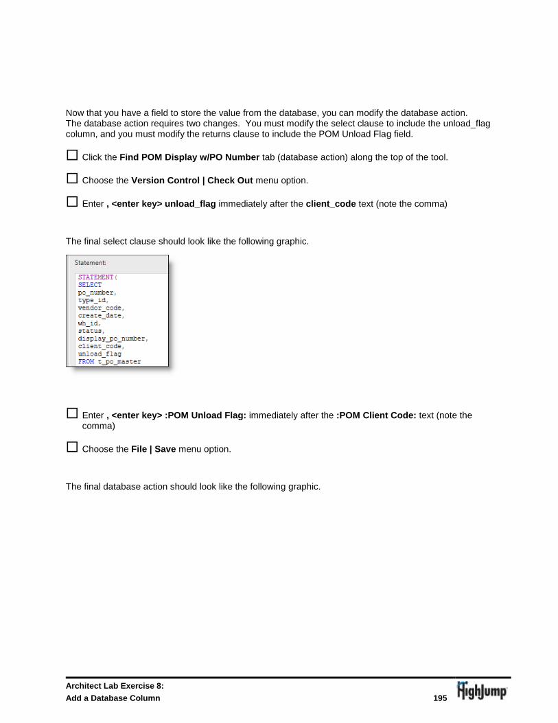
Architect Lab Exercise 8:
Add a Database Column 195
Now that you have a field to store the value from the database, you can modify the database action. The database action requires two changes. You must modify the select clause to include the unload_flag column, and you must modify the returns clause to include the POM Unload Flag field.
Click the Find POM Display w/PO Number tab (database action) along the top of the tool.
Choose the Version Control | Check Out menu option.
Enter , <enter key> unload_flag immediately after the client_code text (note the comma)
The final select clause should look like the following graphic.
Enter , <enter key> :POM Unload Flag: immediately after the :POM Client Code: text (note the comma)
Choose the File | Save menu option.
The final database action should look like the following graphic.

Architect Lab Exercise 8:
Add a Database Column 196
You have modified the database action. It is considered best practice to test the syntax of the database action before you continue development. Follow the procedures below to test the syntax of the modified database action.
Click the Test button on the right side of the window.
Enter the machine name of the database server in the Server Name edit box.
Enter AAD in the Database Name edit box.
Use the SQL Server section of the login.txt file to complete the remaining edit boxes.
Click the Connect button.
The system displays a grid which prompts for all of the fields mentioned in the STATEMENT clause of the database action.

Architect Lab Exercise 8:
Add a Database Column 197
Enter PO5 in the Value edit box for the PO Number row.
Enter 01 in the Value edit box for the Warehouse ID row.
Click the OK button.
The system rebuilds the query with the data supplied in the Input Parameters window. Then it sends the query to the database server. Advantage Architect then shows the result set returned by the database server.
Because the database server returned a result set to Advantage Architect, you know that the STATEMENT clause is syntactically correct.
You have modified the database action to select the unload_flag column from the t_po_master table in the POM Unload Flag field. And you have verified that this database action is used in the Inbound Order Receipt business process. However, in order to meet the warehouse manager’s requirements, you need to perform some validation on the POM Unload Flag field. The validation consists of a compare action and a calculate action. The compare action checks if the POM Unload Flag field equals Y. The calculate action builds an error message if it is something other than Y.
This validation is specific to the PO Number prompt in the Inbound Order Receipt business process. Therefore, the natural place for the validation is in the dialog-centric process object for the PO Number. Follow the procedures below to add the POM Unload Flag validation logic to the PO-related dialog-centric process object.
Right-click the PO Receipt – PO Number tab (process object) along the top of the tool.
Choose the Close All But This menu option.
The system opens the definition of the dialog-centric process object that prompts for a PO Number. The chart that follows gives a brief description of several lines.

Architect Lab Exercise 8:
Add a Database Column 198
Line Number Description
1 Populates several fields with purchase order-related resources which the system will display on the screen. For additional details on this calculate action, please see the exercise titled Exercise 5: Display Text on the Reader.
2 Calls the Dialog process object. Because of the values set in line 1, this process object prompts the user for a Purchase Order and then waits for the user to respond. For additional details on the Dialog process object, please see the exercise titled Exercise 5: Display Text on the Reader.
3 Asks the question, “Did the user press the F1:Cancel function key?”
4 Asks the question, “Did the user provide a value for the purchase order?”
5 Set the PO Number field equal to the value entered by the user.
6 Perform some level of verification against the user-entered value. If the verification passes, continue with line 7. If the verification fails, then continue with line 1.
12 – 14 Builds error messages for actions that fail in other parts of the process object.
From the procedures above, you know that the database action which reads the data from the t_po_master table and populates the POM Unload Flag is buried beneath line 6. Therefore, the validation on the POM Unload Flag must occur after line 6. Additionally, this process object has several calculate actions that build error messages (lines 12 – 14). Therefore, the natural place for the new error message is around lines 12 – 14. Follow the procedures below to add the compare action which checks if the POM Unload Flag field equals Y.

Architect Lab Exercise 8:
Add a Database Column 199
Choose the Version Control | Check Out menu option.
Click the left-most column of line 6 (Call…Verify PO Number) to highlight the line.
Click the Insert After button.
Choose Compare in the Type drop-down box.
Click the Asterisk button on the right side of the Action Name drop down box.
Chose the Compare Action menu option.
Enter POM Unload Flag = Y? In the Action Name edit box.
Click the Checkmark button on the right side of the Action Name drop down box.
After you click the checkmark button, the system creates a new compare action with the given name. Additionally, the system creates a new tab for the new compare action along the top of the tool.
Click the POM Unload Flag = Y? tab (compare action) along the top of the tool.
Choose POM Unload Flag in the Field 1 drop down box.
Click the Asterisk button on the right side of the Field 2 / Constant drop down box.
Choose the Constant – String menu option.
Enter Y in the Field 2 / Constant edit box.
Choose the File | Save menu option.
The finished compare action should look like the following graphic.

Architect Lab Exercise 8:
Add a Database Column 200
You have created the compare action which checks if the POM Unload Flag equals Y and you have added the compare action to the dialog centric process object. The next step is to build the error message that the system displays if the POM Unload Flag does not equal Y. The system displays the value of the SYS_SHORTMSG field when it displays error messages to the user. Therefore, you must create a resource which contains the text of the error message and you must create a calculate action which sets the SYS_SHORTMSG field equal to the resource. Follow the procedures below add the calculate action and the resource to the application.
Right-click the PO Receipt – PO Number tab (process object) along the top of the tool.
Choose the Close All But This menu option.
Click the left-most column of line 15 (Calculate…Err: Input Required) to highlight the line.
Click the Insert After button.
Enter NOT_UNLOAD in the Label edit box.
Choose Calculate in the Type drop-down box.
Click the Asterisk button on the right side of the Action Name drop down box.
Chose the Calculate Action menu option.
Enter Err: PO Not Unloaded in the Action Name edit box.
Click the Checkmark button on the right side of the Action Name drop down box.
After you click the checkmark button, the system creates a new calculate action with the given name. Additionally, the system creates a new tab for the new calculate action along the top of the tool.
Choose SCR TEXT in the Pass drop down box.
Choose SCR TEXT in the Fail drop down box.
Choose NOT_UNLOAD in the Fail drop down box of line 7 (Compare…POM Unload Flag = Y?)
Choose the File | Save menu option.
The finished process object looks like the following graphic. The chart that follows gives a brief description of several lines.

Architect Lab Exercise 8:
Add a Database Column 201
Line Number Description
1 Populates several fields with purchase order-related resources which the system will display on the screen. For additional details on this calculate action, please see the exercise titled Exercise 5: Display Text on the Reader.
2 Calls the Dialog process object. Because of the values set in line 1, this process object prompts the user for a Purchase Order and then waits for the user to respond. For additional details on the Dialog process object, please see the exercise titled Exercise 5: Display Text on the Reader.
3 Asks the question, “Did the user press the F1:Cancel function key?”
4 Asks the question, “Did the user provide a value for the purchase order?”
5 Set the PO Number field equal to the value entered by the user.
6 Perform some level of verification against the user-entered value. If the verification passes, continue with line 7. If the verification fails, then continue with line 1.
7 Asks the question, “Is the POM Unload Flag = Y?” The system populated the POM Unload Flag field somewhere beneath line 6.
13 - 16 Builds error messages for actions that fail in other parts of the process object.
You have created the placeholder for the calculate action which builds the error message. Next you need to define its details. Follow the procedures below to define the content of the calculate action.

Architect Lab Exercise 8:
Add a Database Column 202
Click the Err: PO Not Unloaded tab (calculate action) along the top of the tool.
Click the Insert After button.
Choose Equals in the Operation drop down list.
Choose SYS_SHORTMSG in the Result drop down list.
Click the Asterisk button on the right side of the Operand 1 drop down box.
Choose the Resource menu option.
Enter Err PO Not Unloaded in the Operand 1 edit box.
Click the Checkmark button on the right side of the Action Name drop down box.
After you click the checkmark button, the system creates a new resource with the given name. Additionally, the system creates a new tab for the new resource along the top of the tool.
Choose DEFAULT in the Output Format drop down list.
Choose the File | Save menu option.
The finished calculate action looks like the following graphic.
You have created the placeholder for the resource which holds the translatable text of the error message. Next you need to define its details. Follow the procedures below to define the content of the resource.
Click the Err PO Not Unloaded tab (resource) along the top of the tool.
Enter PO NOT UNLOADED in the Text edit box.

Architect Lab Exercise 8:
Add a Database Column 203
Choose the File | Save menu option.
The finished resource looks like the following graphic.
In the Inbound Order Receipt business process, you have modified a database action to read the unload_flag column from the t_po_master table into the POM Unload Flag field. You have added a compare action which checks if POM Unload Flag field is Y. And you have built an error message which the system displays when it fails that check. With these components, you have made all of the necessary changes to the Advantage Architect objects.

Architect Lab Exercise 8:
Add a Database Column 204
Activity 7: Compile and Activate the Changes (Phase 2)
At this point you have modified several objects to meet the requirements dictated by the warehouse manager. However, if you view the Virtual Terminal, you will see that the changes have had no impact. In order to see the changes reflected on the Virtual Terminal, you must first compile the application and then activate the application. The procedures below are very generic. If you need additional details on how to compile and activate the application, please see the activity titled Compile and Activate the Changes in Exercise 1 of this manual.
Compile the application
There is a known issue with the tool that sometimes causes the compile to fail on certain database actions. If the compile fails with an error similar to the graphic, then follow the instructions below the graphic. Otherwise, skip ahead to the instruction which directs you to activate the application.
Choose the Define | Actions | Database menu option.
Double click the Find POM Display w/PO Number node.
Place the cursor anywhere in the Statement edit box.
Press the Control + A keys to highlight the entire contents of the Statement edit box.
Press the Control + X key to cut the entire contents of the Statement edit box.
Choose the File | Save menu option.
Place the cursor anywhere in the Statement edit box.
Press the Control + V key to copy the clipboard contents into the Statement edit box.
Choose the File | Save menu option.
Compile the application.
Activate the application

Architect Lab Exercise 8:
Add a Database Column 205
Activity 8: Test the Changes (Phase 2)
The chart below outlines the various test cases that must be validated. Each test case defines an action you must take, and it defines the expected outcome based on the requirements. If a given test case does not yield the expected outcome, then review the steps from the previous activity. It is likely that you either missed a step or performed a step incorrectly. The test cases do not detail every keystroke. You need to use the knowledge you gained in the first activity of this exercise in order to test the scenarios.
Starting the Inbound Order Receipt Business Process
From the Main Menu choose Option 1, Option 3, Option 1
Press the F5:New key
Press the Enter Key at the Receipt ID dialog.
Test Case Expected Outcome Pass / Fail
In the Inbound Order Receipt process at the PO Number prompt, enter a PO that has NOT passed through the Unload Inbound Order process.
System displays the PO NOT UNLOADED error message.
Walk through the Unload Inbound Order process. (Main Menu, option 1, option 1…)
System displays Transaction Complete dialog at the end of the Unload Inbound Order process.
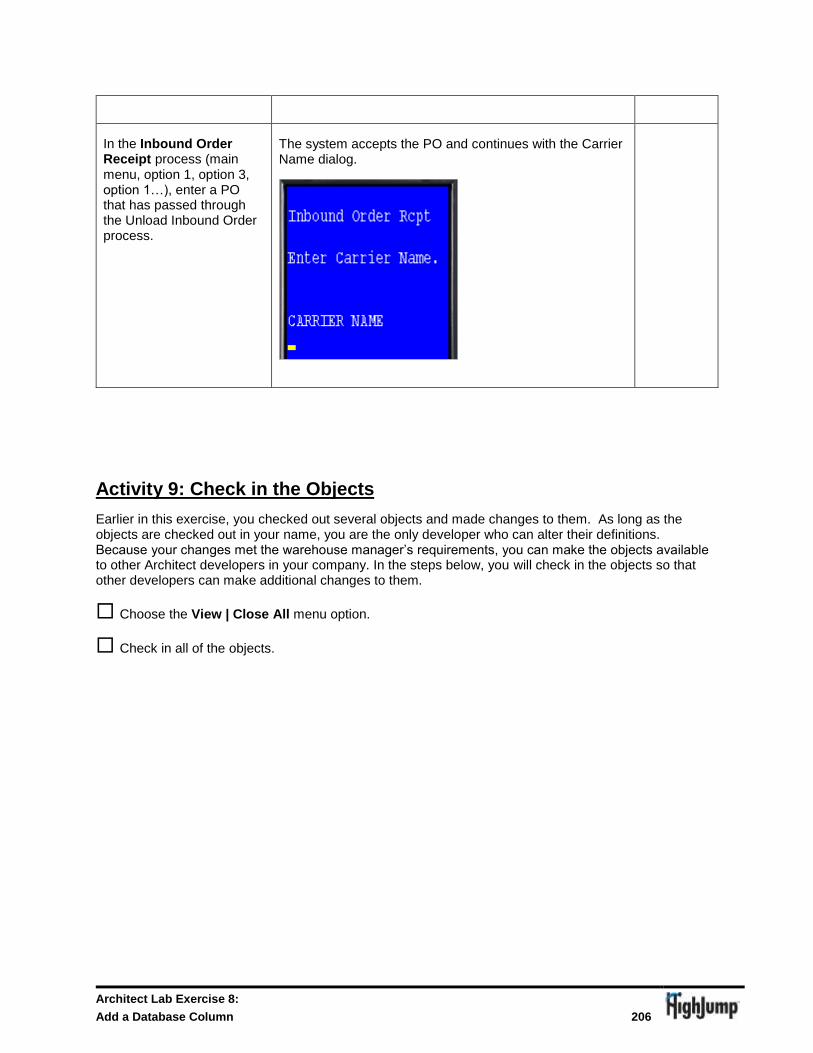
Architect Lab Exercise 8:
Add a Database Column 206
In the Inbound Order Receipt process (main menu, option 1, option 3, option 1…), enter a PO that has passed through the Unload Inbound Order process.
The system accepts the PO and continues with the Carrier Name dialog.
Activity 9: Check in the Objects
Earlier in this exercise, you checked out several objects and made changes to them. As long as the objects are checked out in your name, you are the only developer who can alter their definitions. Because your changes met the warehouse manager’s requirements, you can make the objects available to other Architect developers in your company. In the steps below, you will check in the objects so that other developers can make additional changes to them.
Choose the View | Close All menu option.
Check in all of the objects.
Architect Lab Exercise 9:
Add a Prompt with Validation 207
Architect Lab Exercise 9: Add a Prompt with Validation
Introduction In this exercise you will add a prompt for a department in the Miscellaneous Return business process. Then you will add validation to ensure that the user-entered department is a valid entry.
Background Information This exercise uses the Miscellaneous Return business process as a basis for all activities. The Miscellaneous Return business process manages the receipt of returned items into the warehouse. For example, the warehouse manager may issue some inventory to the marketing team for an upcoming marketing event. When the marketing team returns from the event, they may return the inventory to the warehouse. The material handlers in the warehouse might use the Miscellaneous Return business process to receive the inventory back into the warehouse.
This exercise places a strong emphasis on dialog actions. In a previous exercise, you reviewed the online material for dialogs and screen formats. If necessary, take a second look at the online lessons.
1. Open the Advantage Architect online course.
2. Review the Resources, Screen Formats, and Dialog Actions topic.

Architect Lab Exercise 9:
Add a Prompt with Validation 208
Activity 1: Understand the Current Process
This activity demonstrates the Miscellaneous Return business process on the RF terminal. Follow the procedures below to see how the Miscellaneous Return process operates in the base application.
Log in to the Virtual Terminal as AMY / AMY / FAAMY.
Enter option 1 (the Receipts menu.)
Press the F8 key to scroll down one page.
Enter option 7 (the Misc Return menu.)
Enter a unique order number at the Control Number dialog. (MR001, MR002, MR003 are unique)
Press the F2 key (Switch) at the LP dialog.
Enter any valid item at the Item Number dialog. (NNFG00000 and NNRM00000 are valid items.)
Enter any number at the Eaches dialog.
Enter 0 at the Label Quantity dialog. (The label interface is not enabled.)
Press the F3 key (Done) at the Item Number dialog.
Enter the suggested location at the Location dialog.
Press the Enter key to accept the defaulted Quantity value.
Press the Enter key at the Transaction Complete dialog.
Press the F1 key (Cancel) at the Control Number dialog to return to the menu.
Activity 2: Understand the Requirements
This activity identifies the changes that the warehouse manager wants to make to the Miscellaneous Return business process.
The warehouse manager calls you on the phone. He explains that they almost always use the Miscellaneous Return business process in conjunction with inventory that has been issued to another department. He notes that the marketing team and sales team often take inventory for their marketing and sales events. Then they return the inventory to the warehouse after the events. Since the warehouse frequently uses Miscellaneous Return with other departments in the company, the warehouse manager would like to add a prompt for Department name to the process. Additionally, the warehouse manager would like to verify that the system only accepts certain values at the department prompt. Lastly, the warehouse manager would like to send the user-entered department to the host system.
The two of you work together on a design, and you agree that the system will prompt for the department immediately after the system prompts for the control number. You also agree that the best way to limit

Architect Lab Exercise 9:
Add a Prompt with Validation 209
the values at the prompt is to store the valid departments in a table in the database. You agree that the system should display the department prompt to the user in the following manner.
Activity 3: Develop the Changes (Phase 1)
In order to meet the warehouse manager’s requirements you must introduce the following changes to the Miscellaneous Return business process. 1. Add the department prompt 2. Validate the user-entered department against a new database table 3. Include the department in the data sent to the host In this exercise, you will build and test the changes in three phases. In each phase, you will address one of the numbered items from above. In the first phase, you will add a department prompt to the Miscellaneous Return business process.
In the exercise titled Exercise 5: Display Text on the Reader you learned about the Dialog process object. And in the exercise titled Exercise 7: Add a New Business Process you learned about dialog-centric process objects. In this exercise, you will merge those two concepts and create a new department prompt. The Warehouse Advantage base application contains a multitude of dialog-centric process objects for various prompts. Rather than building a department prompt from scratch, you will copy an existing item-related dialog-centric process object from another business process and then replace the item-related components with department-related components. Perform the following procedures to build a department-related dialog-centric process object for the Miscellaneous Return business process.
In Advantage Architect, double click WA in the Repository tab.
Choose the Define | Process Object menu option.
Right click the Adjust - Item node.
Choose the Copy As menu option.
The system displays the Copy As window.

Architect Lab Exercise 9:
Add a Prompt with Validation 210
Enter Receipt - Department in the New Object Name edit box.
Click the OK button.
The system creates a new process object. The name of the dialog-centric process object is a bit non-standard. You might expect that the name would be Misc Return – Department. However, in a couple pages you will see that all of the dialog-centric process objects in the Miscellaneous Return business process object begin with a “Receipt” tag. The reason for the non-standard name is to remain consistent with the other dialog centric process objects in the same business process object. The finished process object should look like the following graphic. The chart that follows gives a brief description of several lines.
Line Number Description
2 Populates the fields with item-related resources which the system will display on the screen. For additional details on this calculate action, please see the exercise titled Exercise 5: Display Text on the Reader.
3 Calls the Dialog process object. Because of the values set in line 2, this process object prompts the user for an item and then waits for the user to respond. For

Architect Lab Exercise 9:
Add a Prompt with Validation 211
additional details on the Dialog process object, please see the exercise titled Exercise 5: Display Text on the Reader.
6 Populates the Item ID field with the user-entered value.
7 Verifies that the user-entered value exists in the item master table.
Because this process object was copied from an item-related dialog-centric process object, it contains several item-related components. Lines 1, 2, 6, and 7 contain item –related logic that must be removed or replaced with department-related logic. Line 2 populates the fields with the text that will be displayed on the screen. Follow the procedures below to replace the item-related screen elements with department-related screen elements.
Click the Action Name column of line 2 (Calculate…ScrTxt: Enter Item Number) to bring focus.
Double click the Action Name column of line 2 (Calculate…ScrTxt: Enter Item Number).
Choose the File | Copy As menu option.
The system displays the Copy As window.
Enter ScrTxt: Enter Department in the New Object Name edit box.
Click the OK button.
The system creates a new calculate action that should look like the following graphic. The chart that follows gives a brief description of some of its content.

Architect Lab Exercise 9:
Add a Prompt with Validation 212
Field Value Details
Dialog Type PROMPT Indicates that the user will scan or enter a value at a prompt. The system does not display this field on the screen.
Dialog Field <Empty> There is no default item number, so this field remains empty.
Dialog Prompt ITEM ID This is the prompt title. The system displays the value on the screen.
SCR_HELP Scan the item number.
This is the instruction to the user. The system displays the value on the screen
The Dialog Prompt field holds the title of the prompt which generally appears in all capitals on the screen. In the new department prompt, the Dialog Prompt will hold a value of DEPARTMENT. Follow the procedures below to add the DEPARTMENT prompt title on the screen.
Click the Operand1 cell of line 3 (Dialog Prompt = PROMPT Item ID) to bring focus.
Click the Asterisk button to the right of the Operand 1 drop down box.
Choose the Resource menu option.
Enter PROMPT Department in the Operand 1 edit box.
Click the Checkmark button on the right side of the Operand 1 edit box.
After you click the checkmark button, the system creates a new resource with the given name. Additionally, the system adds a tab along the top of the tool for the new resource.
Choose the File | Save menu option.
The screen text calculate action looks like the following graphic.

Architect Lab Exercise 9:
Add a Prompt with Validation 213
You have created a placeholder for the resource which will hold the DEPARTMENT text. Follow the procedures below add the details to the new resource.
Click the PROMPT Department tab (resource) along the top of the tool.
Enter DEPARTMENT in the Text edit box.
Choose the File | Save menu option.
The finished resource looks like the following graphic.
Right-click the PROMPT Department tab (resource) along the top of the tool.
Choose the Close menu option.
You have accounted for the prompt title. In addition to the prompt title you must also account for the instruction to the user. Follow the procedures below to add the “Enter the department.” instruction on the screen.
Click the ScrTxt: Enter Department tab (calculate action) along the top of the tool.
Click the Operand1 cell of line 4 (SCR_HELP = Scr Enter Item ID) to bring focus.

Architect Lab Exercise 9:
Add a Prompt with Validation 214
Click the Asterisk button to the right of the Operand 1 drop down box.
Choose the Resource menu option.
Enter Scr Enter Department in the Operand 1 edit box.
Click the Checkmark button on the right side of the Operand 1 edit box.
After you click the checkmark button, the system creates a new resource with the given name. Additionally, the system adds a tab along the top of the tool for the new resource.
Choose the File | Save menu option.
The finished screen text calculate action looks like the following graphic.
You have created a placeholder for the resource which will hold the “Enter the Department.” instruction text. Follow the procedures below add the details to the new resource.
Click the Scr Enter Department tab (resource) along the top of the tool.
Enter Enter the Department. in the Text edit box.
Choose the File | Save menu option.
The finished resource looks like the following graphic.

Architect Lab Exercise 9:
Add a Prompt with Validation 215
You have built a screen text calculate action that accounts for the prompt title (“DEPARTMENT”) and the prompt instruction (“Enter the department.”) However, the screen text calculate action is currently not called from any process object. In order for the system to utilize the new resources you must include the screen text calculate action in a dialog-centric process object. Follow the procedures below to add the new screen text calculate action to the department-related dialog centric process object for the Miscellaneous Return business process.
Click the Receipt – Department tab (process object) along the top of the tool.
Choose ScrTxt: Enter Department in the Action Name drop down box of line 2 (Calculate…ScrTxt: Enter Item Number)
Choose the File | Save menu option.
The department-related dialog centric process object should look like the following graphic.
You have accounted for the department-related text elements that appear on the screen. However, there are additional item-related components in this process object that must be handled. The Dialog process object is the object that displays the screen on the terminal and waits for the user to respond. Regardless of the parent business process object, the Dialog process object always populates the field called Dialog Field with the value entered by the user. Dialog Field has a very generic name. Therefore the conventions dictate that the dialog-centric process object should copy the value of Dialog Field into another field with a more specific name. In the current process object, this occurs on line 6, where the

Architect Lab Exercise 9:
Add a Prompt with Validation 216
system populates a field called Item ID with the value entered by the user. In the modified version you will create a new field called Department and then populate it with the value entered by the user at the department prompt. Follow the procedures below to create a new field called Department.
Right-click the Receipt – Department tab (process object) along the top of the tool.
Choose the Close All But This menu option.
Choose the Define | Field menu option.
Choose the File | New menu option.
Enter Department in the Name edit box.
Enter 30 in the Length edit box.
Choose the File | Save menu option.
The finished field should look like the following graphic.
You have created a new field. Follow the procedures below to create a calculate action which populates the Department field with the value entered by the user.
Click the Receipt – Department tab (process object) along the top of the tool.
Click the Action Name column of line 6 (Calculate…Item ID = Dialog Field) to bring focus.
Double click the Action Name column of line 6 (Calculate…Item ID = Dialog Field).
Choose the File | Copy As menu option.
The system opens the Copy As window.

Architect Lab Exercise 9:
Add a Prompt with Validation 217
Enter Department = Dialog Field in the New Object Name edit box.
Click the OK button.
Choose Department in the Result drop down box.
Choose the File | Save menu option
The finished calculate action should look like the following graphic.
In order for the system to utilize this new calculate action, you need to call it from the dialog-centric process object. Follow the procedures below to replace the item-related calculate action with the department-related calculate action in the dialog-centric process object.
Click the Receipt – Department tab (process object) along the top of the tool.
Choose Department = Dialog Field in the Action Name drop down box of line 6 (Calculate…Item ID = Dialog Field)
Choose the File | Save menu option.
The department-related dialog centric process object should look like the following graphic.

Architect Lab Exercise 9:
Add a Prompt with Validation 218
You have accounted for the department-related text elements that appear on the screen. And you have accounted for populating the Department field with the value entered by the user. However, there are additional item-related components in this process object that must be handled. Line 1 of this process object is a simple calculate action that is directly related to items. You will delete this line, as it is not relevant to departments. Additionally, line 7 verifies that the user-entered value exists in the item master table. This, too, is not related to departments. In Phase 2 of this exercise, you will replace this verification with rules that verify the user-entered department against a database table. For now, you will simply comment out the line. Follow the procedures below to remove line 1 and to comment line 7.
Click the left-most column of Line 1 (Calculate…Client Code = “”) to highlight the row.
Click the Delete button.
Double click the second column from the left of Line 6 (Call…Verify Item) to create a comment.
Choose the File | Save menu option.
The process object should look like the following graphic. The chart that follows gives a brief description of several lines.

Architect Lab Exercise 9:
Add a Prompt with Validation 219
Line Number Description
1 Populates the fields with department-related resources which the system will display on the screen. For additional details on this calculate action, please see the exercise titled Exercise 5: Display Text on the Reader.
2 Calls the Dialog process object. Because of the values set in line 1, this process object prompts the user for a department and then waits for the user to respond. For additional details on the Dialog process object, please see the exercise titled Exercise 5: Display Text on the Reader.
3 Asks the question, “Did the user press the F1:Cancel function key?”
4 Asks the question, “Did the user provide a value on the screen”
5 Populates the Department field with the user-entered value.
10 - 12 Builds error messages for actions that fail in other parts of the process object.
You have built a department-related, dialog-centric process object. However, if you stop here, the Miscellaneous Return business process will not prompt for a department. In order to include the department prompt, you must call the dialog-centric process object from within the business process object. Follow the procedures below to include the department prompt in the Miscellaneous Return business process.
Choose the View | Close All menu option.
Choose the Define | Business Process menu option.
Double click the Miscellaneous Return node.

Architect Lab Exercise 9:
Add a Prompt with Validation 220
The system opens the definition of the business process object. The chart that follows gives a brief description of several lines.
Line Number Description
4 Establish the transaction code unique to the Miscellaneous Return business process.
5 Prompt for a Control Number. This is a dialog-centric process object.
7 Prompt for a Labor Advantage Receipt Location. This is a dialog-centric process object. (Only used when Labor Advantage module is installed.)
8 Prompt for an LP. This is a dialog-centric process object.
The warehouse manager wants the system to prompt for the department immediately after it prompts for a control number. If you use the skills you learned in the exercise titled Exercise 7: Add a New Business Process, you will be able to easily identify line 6 as the dialog-centric process object which prompts for a control number. The department prompt will be added immediately after line 6. Follow the procedures below to add the department-related, dialog-centric process object to the Miscellaneous Return business process object.
Choose the Version Control | Check Out menu option.
Click the left-most column of line 5 (Call…Receipt – Control Number) to highlight the line.
Click the Insert After button.
Enter DEPT in the Label edit box.
Choose Call in the Type drop-down box.
Choose Receipt - Department in the Action Name drop-down box.
Choose CONTROL in the Fail drop down box.

Architect Lab Exercise 9:
Add a Prompt with Validation 221
Choose the File | Save menu option.
The process object should look like the following graphic. The chart that follows gives a brief description of several lines.
Line Number Description
4 Establish the transaction code unique to the Miscellaneous Return business process.
5 Prompt for a Control Number. This is a dialog-centric process object.
6 Prompt for a Department. This is a dialog-centric process object.
8 Prompt for a Labor Advantage Receipt Location. This is a dialog-centric process object. (Only used when Labor Advantage module is installed.)
9 Prompt for an LP. This is a dialog-centric process object.
As a general rule, when the user presses the F1 function key on a screen, the HighJump system navigates backwards in the prompting sequence and returns the user to the previous prompt. In the base application version of the Miscellaneous Return business process, the prompting sequence goes from Control Number to LP (or Item). Therefore, when the user presses the F1 function key on the LP (or Item) prompt, the system navigates backwards to the Control Number prompt. However, now you have introduced a new prompt into the sequence. Consequently, the F1 function key path must also change. When the user presses the F1 function key on the LP (or Item) prompt, the system must navigate backwards to the Department prompt. Follow the procedures below to change the F1 function key path on the LP prompt and the Item prompt.
Choose DEPT in the Fail drop down box of line 11 (Compare…<F3:Done>?)
Choose DEPT in the Pass drop down box of line 15 (Compare…HU ID = “”?)
Choose the File | Save menu option.

Architect Lab Exercise 9:
Add a Prompt with Validation 222
The process object should look like the following graphic.
You have built a department-related, dialog-centric process object. You have included it in the Miscellaneous Return business process object. And you have accounted for the F1 function key path. You have modified all of the Advantage Architect objects necessary to prompt for a department in Miscellaneous Return. Phase 1 of the development cycle is complete. You still need to verify the department against a database table. And you still need to include the department in the transaction sent to the host. However, you will perform those procedures later in this exercise.
Activity 4: Compile and Activate the Changes (Phase 1)
At this point you have modified several objects to meet the requirements dictated by the warehouse manager. However, if you run the process on the Virtual Terminal, you will see that your changes have not taken effect. In order for your changes to take effect, you must first compile the application and then activate the application. The procedures below are very generic. If you need additional details on how to compile and activate the application, please see the activity titled Compile and Activate the Changes in the exercise titled Exercise 1: Introduction to Advantage Architect.
Compile the application
Activate the application

Architect Lab Exercise 9:
Add a Prompt with Validation 223
Activity 5: Test the Changes (Phase 1)
The chart below outlines the various test cases that must be validated. Each test case defines an action you must take, and it defines the expected outcome based on the requirements. If a given test case does not yield the expected outcome, then review the steps from the previous activity. It is likely that you either missed a step or performed a step incorrectly. The test cases do not detail every keystroke. You need to use the knowledge you gained in the first activity of this exercise in order to test the scenarios.
Starting the Miscellaneous Return Business Process
From the Main Menu choose Option 1, F8, Option 7
Test Case Expected Outcome Pass / Fail
Enter MR002 at the Control Number prompt.
System advances to the Department prompt.
Enter ABC at the Department dialog.
System advances to the LP dialog.
Press the F2 key at the Department prompt.
System displays the INVALID OPTION error.

Architect Lab Exercise 9:
Add a Prompt with Validation 224
Press the F1 key at the Department dialog.
System returns to the Control Number dialog.
Press the F1 key at the LP dialog.
System returns to the Department dialog.
Press the F1 key at the Item Number dialog.
System returns to the Department dialog.

Architect Lab Exercise 9:
Add a Prompt with Validation 225

Architect Lab Exercise 9:
Add a Prompt with Validation 226
Activity 6: Develop the Changes (Phase 2)
In Phase 1 you introduced a prompt for a department into the Miscellaneous Return business process. In Phase 2 of the development process you will add validation to the user-entered department. The warehouse manager wants to limit the departments which the user can enter. And the two of you agreed that the best way of managing that validation was to store the valid departments in a database table. At the core of the department validation is a database table which stores the departments. Follow the procedures below to add the department table to the database and to populate it with sample data.
Open Microsoft SQL Server Management Studio. (For additional details, please see the activity titled Develop the Changes in exercise Exercise 4: Calculate Actions of this manual.)
Choose the File | Open | File menu.
Click the Desktop button on the left panel.
Navigate to the Training \ Architect \ SQL folder.
Click the create_t_department.sql file.
Click the Open button.
The system opens the file in a new tab.
Choose the Query | Execute menu.
The system runs the script which builds the t_department table and populates it with sample data. At the end of the script, it selects the data from the table. The graphic below shows the data in the table and a brief description of each column in the table

Architect Lab Exercise 9:
Add a Prompt with Validation 227
Column Name
Description
dept_name The department name. This column contains the valid values that the user will enter at the department prompt on the terminal.
wh_id The warehouse ID.
description A description of the department
manager The manager of the department. This references an employee in the t_employee table.
In a few pages you will create a database action which reads a row out of the t_department table. The database action will serve as the basis for validating user input, and it will look similar to the following:
SELECT dept_name, wh_id, description, manager FROM t_department WHERE dept_name = :Department: AND wh_id = :Warehouse ID:
Note that the statement selects the data from four columns in the table. In order for this statement to work correctly, you must store the value from each column into an Architect field. In the next several steps you will create the following fields: DPT Dept Name, DPT Whse ID, DPT Description, and DPT Manager. Each of these four fields corresponds with a selected column from the database action, and it will store the corresponding values returned by the database.
Choose the Define | Field menu option.
Choose the File | New menu option.
Enter DPT Department in the Name edit box.
Enter 30 in the Length edit box.
Choose the File | Save menu option.

Architect Lab Exercise 9:
Add a Prompt with Validation 228
The finished field looks like the following graphic.
Choose the File | Copy As menu option.
The system displays the Copy As window.
Enter DPT Whse ID in the New Object Name edit box.
Click the OK button.
Enter 10 in the Length edit box.
Choose the File | Save menu option.
The finished field looks like the following graphic.

Architect Lab Exercise 9:
Add a Prompt with Validation 229
Choose the File | Copy As menu option.
The system displays the Copy As window.
Enter DPT Description in the New Object Name edit box.
Click the OK button.
Enter 50 in the Length edit box.
Choose the File | Save menu option.
The finished field looks like the following graphic.
Choose the File | Copy As menu option.
The system displays the Copy As window.

Architect Lab Exercise 9:
Add a Prompt with Validation 230
Enter DPT Manager in the New Object Name edit box.
Click the OK button.
Enter 30 in the Length edit box.
Choose the File | Save menu option.
The finished field looks like the following graphic.
You have created four fields which will store the data from the four columns in the database action. Next you will create the database action which includes the select statement and the reference to the four fields.
Choose the View | Close All menu option.
Choose the Define | Database (Actions) menu option.
Choose the File | New menu option.
Enter Find DPT w/Dept in the Name edit box.
Enter the following query into the Statement multi-line edit box.
STATEMENT ( SELECT dept_name, wh_id, description, manager FROM t_department WHERE dept_name = :Department: AND wh_id = :Warehouse ID: )

Architect Lab Exercise 9:
Add a Prompt with Validation 231
RETURNS ( :DPT Department: , :DPT Whse ID: , :DPT Description: , :DPT Manager: )
Choose the File | Save menu option. The finished database action should look like the following graphic.
You have created a database action that selects all columns from the t_department table for a given department and warehouse. And you have instructed the HighJump system to store the returned data into four Advantage Architect fields (DPT Department, DPT Whse ID…..). The database action is complete. However, before you navigate away from the database action it is beneficial to test its syntax. Follow the procedures below to test the syntax of the database action.
Click the Test button on the right side of the window.
Enter the machine name of the database server in the Server Name edit box.
Enter AAD in the Database Name edit box.
Use the SQL Server section of the login.txt file to complete the remaining edit boxes.
Click the Connect button.
The system displays a grid which prompts for all of the fields mentioned in the STATEMENT clause of the database action.

Architect Lab Exercise 9:
Add a Prompt with Validation 232
Enter SALES in the Value edit box for the Department row.
Enter 01 in the Value edit box for the Warehouse ID row.
The finished Input Parameters window should look like the following graphic.
Click the OK button.
The system rebuilds the query with the data supplied in the Input Parameters window. Then it sends the query to the database server. The database server processes the query and sends the result set back to Advantage Architect. Advantage Architect then displays the result set.
Because the database server returned a result set to Advantage Architect, you know that the STATEMENT clause is syntactically correct. You will now continue with building the wrapper for the database action.
You have created a database action which retrieves a row from the t_department table and stores the returned data into four fields. According to the development standards, every database action should be embedded in a database action wrapper process object. For additional details on process object wrappers for database actions, please see the exercise titled Exercise 7: Add a Database Column. The

Architect Lab Exercise 9:
Add a Prompt with Validation 233
Warehouse Advantage base application contains a multitude of database wrapper process objects in the base application. Rather than build the wrapper from scratch, you will copy an existing one and then modify it for the database action you created. Follow the procedures below to build a database wrapper process object for the new database action.
Choose the View | Close All menu option.
Choose the Define | Process Object menu option.
Right click the DBFind LOC w/Loc node.
Choose the File | Copy As menu option.
The system displays the Copy As window.
Enter DBFind DPT w/Dept in the New Object Name edit box.
Click the OK button.
The system creates a new process object that should look like the following graphic. The chart that follows gives a brief description of several lines.

Architect Lab Exercise 9:
Add a Prompt with Validation 234
Line Number Description
1 Ask the question “Is the Location field empty?”
2 Build and send a database query to the database server. The query returns a row from the location master table for a given location ID. This line is at the core of database wrapper process object.
3 - 4 Handles the case when the database action fails.
6 Build an error message, which the system will eventually display to the user.
7 - 8 Build a log message and send the message to the HighJump platform log.
The process object follows the standard layout for a database wrapper process object. Line 1 and line 2 are the only lines that you need to replace with the department-related components. All of the other lines are generic and can remain untouched. Follow the procedures below to replace line 2 with the new department-related database action.
Choose Find DPT w/Dept in the Action Name drop down box of line 2 (Database…Find LOC w/Loc)
The database action which you created contains a reference to the Department field in the STATEMENT clause. If the Department field has no value, then it makes no sense to send the query to the database server, because the database server will not find any matching rows. A compare action can test if the Department field has a value and it can conditionally branch around the database action if necessary. Follow the procedures below to build a compare action which tests if the Department field is empty and to include it in the database wrapper process object.
Click the Action Name column of line 1 (Compare…Location = “”?) to bring focus.
Click the Asterisk button on the right side of the Action Name drop down box.
Chose the Compare Action menu option.
Enter Department = “”? In the Action Name edit box.
Click the Checkmark button on the right side of the Action Name drop down box.
After you click the checkmark button, the system creates a new compare action with the given name. Additionally, the system adds a tab along the top of the tool for the new compare action.
Choose the File | Save menu option.
The finished database wrapper process object looks like the following graphic. The chart that follows gives a brief description of several lines.

Architect Lab Exercise 9:
Add a Prompt with Validation 235
Line Number Description
1 Ask the question “Is the Department field empty?”
2 Builds an SQL query and sends it to the database server. The query returns a row from the t_department table for a given department and warehouse. This line is at the core of database wrapper process object.
3 - 4 Handles the case when the database action fails.
6 Build an error message, which the system will eventually display to the user.
7 - 8 Build a log message and send the message to the HighJump platform log.
You have built a database wrapper process object for the new database action. And you have created a placeholder for the compare action which checks if the Department field has a value. Follow the procedures below to add the details to the compare action.
Click the Department = “”? tab (compare action) along the top of the tool.
Choose Department in the Field 1 drop down box.
Click the asterisk button to the right of the Field 2 / Constant drop down box.
Choose the Constant – String menu option.
Choose the File | Save menu option.
The finished compare action should look like the following graphic.

Architect Lab Exercise 9:
Add a Prompt with Validation 236
You have built a process object wrapper for a database action. Next you will build a verification process object that utilizes the wrapper. The purpose of the verification process object is to determine if the user-entered department is valid. If it is valid, the verification process object returns PASS. Otherwise, it builds an error message and returns FAIL. The finished verification process object will look like the following graphic. The chart that follows gives a brief description of several lines.
Line Number Description
1 Calls a process object wrapper for a database action. The process object wrapper builds an SQL query and sends it to the database server. The query attempts to find a row in the t_department table that matches the user-entered department.
2 The system asks the question, “Did the previous database action (from the wrapper) return at least 1 row?” Asked another way, “Does the user-entered department exist in the department table?”
4 Builds an error message, which the system will eventually display to the user.
Follow the procedures below to create a process object shell that will eventually contain all of the verification rules for the department.
Choose the View | Close All menu option
Choose the Define | Process Object menu option.

Architect Lab Exercise 9:
Add a Prompt with Validation 237
Choose the File | New menu option.
Enter Verify Department in the Name edit box.
Click the Properties button to collapse the header information.
Choose the File | Save menu option.
At this point, you have a basic process object to which you can add additional actions.
The verification process object first runs an SQL query which attempts to find a row in the t_department table containing a dept_name column that matches the user input. Basically it calls the process object wrapper you created in the previous steps. Follow the procedures to add the process object wrapper to the verification process object.
Click the left-most column of line 1 (Return…PASS) to highlight the row.
Click the Insert Before button.
Choose Call in the Type drop-down box.
Choose DBFind DPT w/Dept in the Action Name drop-down box.
Choose FAILURE in the Fail drop down box.
The process object should look like the following graphic.
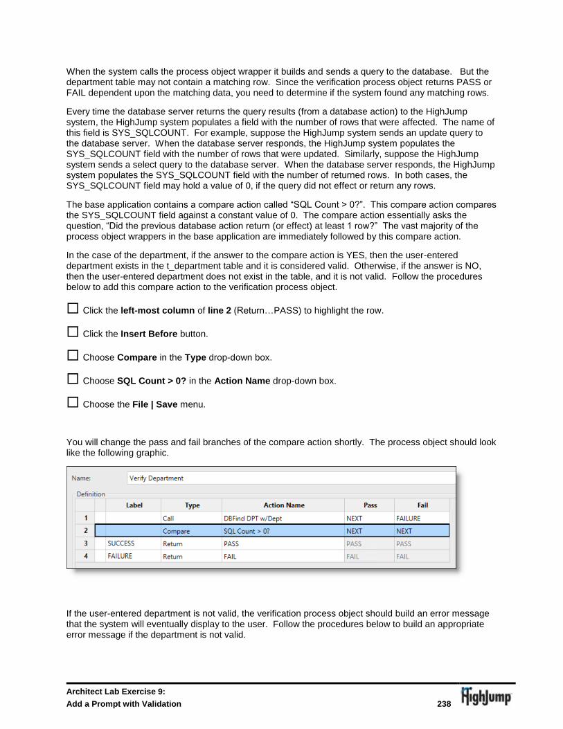
Architect Lab Exercise 9:
Add a Prompt with Validation 238
When the system calls the process object wrapper it builds and sends a query to the database. But the department table may not contain a matching row. Since the verification process object returns PASS or FAIL dependent upon the matching data, you need to determine if the system found any matching rows.
Every time the database server returns the query results (from a database action) to the HighJump system, the HighJump system populates a field with the number of rows that were affected. The name of this field is SYS_SQLCOUNT. For example, suppose the HighJump system sends an update query to the database server. When the database server responds, the HighJump system populates the SYS_SQLCOUNT field with the number of rows that were updated. Similarly, suppose the HighJump system sends a select query to the database server. When the database server responds, the HighJump system populates the SYS_SQLCOUNT field with the number of returned rows. In both cases, the SYS_SQLCOUNT field may hold a value of 0, if the query did not effect or return any rows.
The base application contains a compare action called “SQL Count > 0?”. This compare action compares the SYS_SQLCOUNT field against a constant value of 0. The compare action essentially asks the question, “Did the previous database action return (or effect) at least 1 row?” The vast majority of the process object wrappers in the base application are immediately followed by this compare action.
In the case of the department, if the answer to the compare action is YES, then the user-entered department exists in the t_department table and it is considered valid. Otherwise, if the answer is NO, then the user-entered department does not exist in the table, and it is not valid. Follow the procedures below to add this compare action to the verification process object.
Click the left-most column of line 2 (Return…PASS) to highlight the row.
Click the Insert Before button.
Choose Compare in the Type drop-down box.
Choose SQL Count > 0? in the Action Name drop-down box.
Choose the File | Save menu.
You will change the pass and fail branches of the compare action shortly. The process object should look like the following graphic.
If the user-entered department is not valid, the verification process object should build an error message that the system will eventually display to the user. Follow the procedures below to build an appropriate error message if the department is not valid.

Architect Lab Exercise 9:
Add a Prompt with Validation 239
Click the left-most column of line 3 (Return…PASS) to highlight the row.
Click the Insert After button.
Enter BAD_DEPT in the Label edit box.
Choose Calculate in the Type drop-down box.
Click the asterisk button to the right of the Action Name drop down box.
Choose the Calculate Action menu option.
Enter Err: Invalid Department in the Action Name edit box.
Click the Checkmark button on the right side of the Action Name drop down box.
After you click the checkmark button, the system creates a new calculate action with the given name. Additionally, the system adds a tab along the top of the tool for the new calculate action.
Choose BAD_DEPT in the Fail drop down box of line 2 (Compare…SQL Count > 0?)
Choose the File | Save menu option
The finished verification object looks like the following graphic. The chart that follows gives a brief description of several lines.
Line Number Description
1 Calls a process object wrapper for a database action. The process object wrapper builds an SQL query and sends it to the database server. The query

Architect Lab Exercise 9:
Add a Prompt with Validation 240
attempts to find a row in the t_department table that matches the user-entered department.
2 The system asks the question, “Did the previous database action (from the wrapper) return at least 1 row?” Asked another way, “Does the user-entered department exist in the department table?”
4 Builds an error message, which the system will eventually display to the user.
You have built a placeholder for the calculate action which holds the error message used when the user enters an invalid department. The system displays the value of the SYS_SHORTMSG field whenever it displays error messages to the user. Therefore, you must create a resource which contains the text of the error message and you must modify the calculate action to set the SYS_SHORTMSG field equal to the resource. Follow the procedures below to define the details of the calculate action that handles the error message.
Click the Err: Invalid Department tab (calculate action) along the top of the tool.
Click the Insert After button.
Choose Equals in the Operation drop down list.
Choose SYS_SHORTMSG in the Result drop down list.
Click the Asterisk button on the right side of the Operand 1 drop down box.
Choose the Resource menu option.
Enter Err Invalid Department in the Operand 1 edit box.
Click the Checkmark button on the right side of the Action Name drop down box.
After you click the checkmark button, the system creates a new resource with the given name. Additionally, the system creates a new tab for the new resource along the top of the tool.
Choose Default in the Output Format drop down list.
Choose the File | Save menu option.
The finished calculate action should look like the following graphic.

Architect Lab Exercise 9:
Add a Prompt with Validation 241
You have created the placeholder for the resource which holds the translatable text of the error message. Next you need to define its details. Follow the procedures below to define the content of the resource.
Click the Err Invalid Department tab (resource) along the top of the tool.
Enter INVALID DEPARTMENT in the Text edit box.
Choose the File | Save menu option.
The finished resource should look like the following graphic.
You have built a verification process object that determines the validity of a user-entered department. If the department is valid, the process object exits with a PASS condition. If the department is not valid, the system builds an error message and exits with a FAIL condition. However, the Miscellaneous Return business process will still not check the validity of the user-entered department. In order for the system to check its validity, the verification process object must be added to the dialog-centric process object related to the department. Follow the procedures below to add the verification process object to the dialog-centric process object.
Choose the Define | Process Object menu option.
Double click the Receipt – Department node.
The system opens the current definition of the process object.

Architect Lab Exercise 9:
Add a Prompt with Validation 242
In Phase 1 of this exercise you intentionally commented out line 6. As a result, any value entered by the user at the department prompt is considered valid. To add the department verification logic, you will uncomment line 6, and then replace the item verification logic with the department verification logic.
Double click the second column from the left of line 6 (Call…Verify Item) to remove the comment.
Choose Verify Department in the Action Name drop down box of line 6 (Call…Verify Item)
Choose the File | Save menu option.
The final dialog-centric process object for the department in the Miscellaneous Return business process should look like the following graphic. The chart that follows gives a brief description of several lines.

Architect Lab Exercise 9:
Add a Prompt with Validation 243
Line Number Description
1 Populates the fields with department-related resources which the system will display on the screen. For additional details on this calculate action, please see the exercise titled Exercise 5: Display Text on the Reader.
2 Calls the Dialog process object. Because of the values set in line 1, this process object prompts the user for a department and then waits for the user to respond. For additional details on the Dialog process object, please see the exercise titled Exercise 5: Display Text on the Reader.
3 Asks the question, “Did the user press the F1:Cancel function key?”
4 Asks the question, “Did the user provide a value on the screen”
5 Populates the Department field with the user-entered value.
6 Verifies that the user-entered department exists in the department table. If it doesn’t exist, the system builds an error message.
10 - 12 Builds error messages for actions that fail in other parts of the process object.
You have built a complete dialog-centric process object. The process object captures a department from the user. It validates the user-entered value against the department table in the database. If it is not valid the system builds and displays an error message to the user. Phase 2 of the development cycle is complete. You still need to include the department in the transaction sent to the host. However, you will perform those procedures later in this exercise.

Architect Lab Exercise 9:
Add a Prompt with Validation 244
Activity 7: Compile and Activate the Changes (Phase 2)
At this point you have modified several objects to meet the requirements dictated by the warehouse manager. However, if you run the process on the Virtual Terminal, you will see that your changes have not taken effect. In order for your changes to take effect, you must first compile the application and then activate the application. The procedures below are very generic. If you need additional details on how to compile and activate the application, please see the activity titled Compile and Activate the Changes in the exercise titled Exercise 1: Introduction to Advantage Architect.
Compile the application
Activate the application

Architect Lab Exercise 9:
Add a Prompt with Validation 245
Activity 8: Test the Changes (Phase 2)
The chart below outlines the various test cases that must be validated. Each test case defines an action you must take, and it defines the expected outcome based on the requirements. If a given test case does not yield the expected outcome, then review the steps from the previous activity. It is likely that you either missed a step or performed a step incorrectly. The test cases do not detail every keystroke. You need to use the knowledge you gained in the first activity of this exercise in order to test the scenarios.
Starting the Miscellaneous Return Business Process
From the Main Menu choose Option 1, F8, Option 7
Enter MR003 at the Control Number prompt.
Test Case Expected Outcome Pass / Fail
Enter ABC at the Department prompt.
System displays the INVALID DEPARTMENT error.
Enter SALES at the Department dialog.
System advances to the LP dialog.
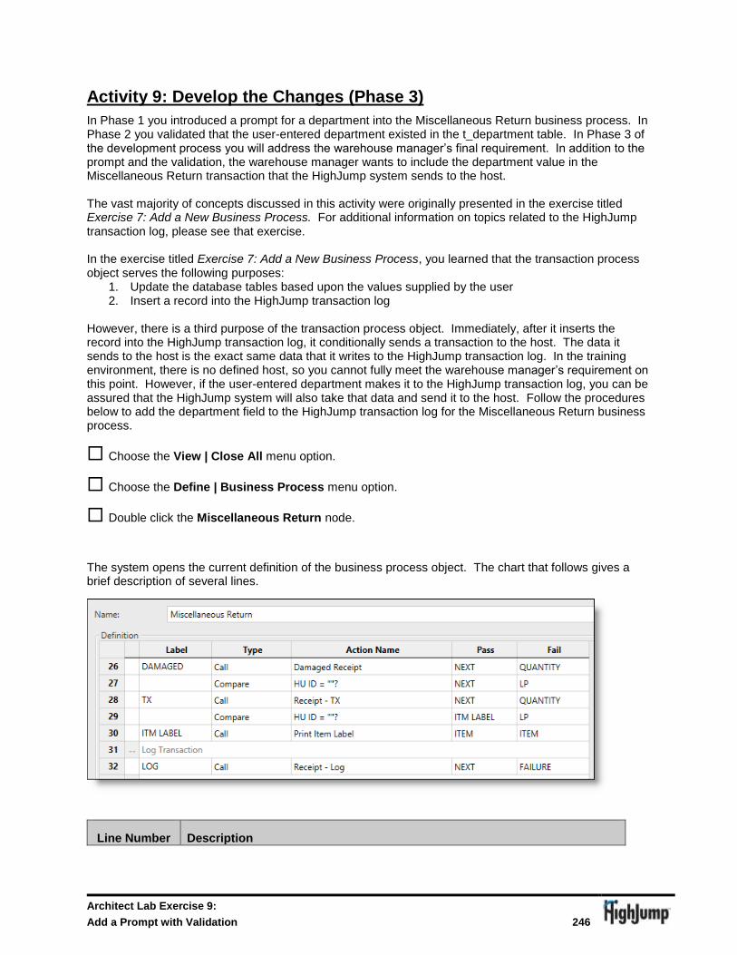
Architect Lab Exercise 9:
Add a Prompt with Validation 246
Activity 9: Develop the Changes (Phase 3)
In Phase 1 you introduced a prompt for a department into the Miscellaneous Return business process. In Phase 2 you validated that the user-entered department existed in the t_department table. In Phase 3 of the development process you will address the warehouse manager’s final requirement. In addition to the prompt and the validation, the warehouse manager wants to include the department value in the Miscellaneous Return transaction that the HighJump system sends to the host. The vast majority of concepts discussed in this activity were originally presented in the exercise titled Exercise 7: Add a New Business Process. For additional information on topics related to the HighJump transaction log, please see that exercise. In the exercise titled Exercise 7: Add a New Business Process, you learned that the transaction process object serves the following purposes:
1. Update the database tables based upon the values supplied by the user 2. Insert a record into the HighJump transaction log
However, there is a third purpose of the transaction process object. Immediately, after it inserts the record into the HighJump transaction log, it conditionally sends a transaction to the host. The data it sends to the host is the exact same data that it writes to the HighJump transaction log. In the training environment, there is no defined host, so you cannot fully meet the warehouse manager’s requirement on this point. However, if the user-entered department makes it to the HighJump transaction log, you can be assured that the HighJump system will also take that data and send it to the host. Follow the procedures below to add the department field to the HighJump transaction log for the Miscellaneous Return business process.
Choose the View | Close All menu option.
Choose the Define | Business Process menu option.
Double click the Miscellaneous Return node.
The system opens the current definition of the business process object. The chart that follows gives a brief description of several lines.
Line Number Description

Architect Lab Exercise 9:
Add a Prompt with Validation 247
28 Calls the transaction process object.
30 Conditionally prints a label on label printer
32 Calls a log-related process object.
Using the naming conventions you learned in the exercise titled Exercise 7: Add a New Business Process, you can identify line 28 as the transaction process object and line 32 as the log process object. Normally, the log process object is a child of the transaction process object. Miscellaneous Return handles them slightly different than the other business processes in the application.
Ultimately, you need to identify the calculate action in this business process that populates the LOG fields in preparation for the insert into the HighJump transaction log. Log-based calculate actions was also a topic presented in the exercise titled Exercise 7: Add a New Business Process. You need to identify the calculate action that looks like the following graphic.
Since this calculate action is part of the log process object, line 32 is a reasonable place to continue looking. Follow the procedures below to continue hunting for the log-based calculate action.
Click the Action Name column of line 32 (Call…Receipt - Log) to bring focus.
Double click the Action Name column of line 32 (Call…Receipt - Log).
The system opens the current definition of the process object.

Architect Lab Exercise 9:
Add a Prompt with Validation 248
Using the naming conventions you learned in the exercise titled Exercise 7: Add a New Business Process, you can identify line 12 as the log process object. The calculate action in question is buried somewhere in that process object. Follow the procedures below to continue hunting for the log-based calculate action.
Click the Action Name column of line 17 (Call…Log - Receipt) to bring focus.
Double click the Action Name column of line 17 (Call…Log - Receipt).
The system opens the current definition of the process object.
Using the naming conventions you learned in the exercise titled Exercise 7: Add a New Business Process, you can identify line 9 as the calculate action which populates the LOG fields with the data that needs to be written to the HighJump transaction log. Follow the procedures below to review the current definition of the log-based calculate action.
Click the Action Name column of line 10 (Calculate…LOG Fill - Receipt) to bring focus.
Double click the Action Name column of line 10 (Calculate…LOG Fill - Receipt).
The system opens the current definition of the calculate action.

Architect Lab Exercise 9:
Add a Prompt with Validation 249
This is the calculate action which populates the LOG fields with the data needed in the HighJump transaction log. These are also the same fields that the system includes in transaction sent to the host. Since you added the Department field to the application, there are no explicit rules on which LOG field to use. However, regardless of which field you choose, you must relay that information to the IT staff which manages the host transactions, so they can build their logic correctly. The LOG Routing Code field is large enough to hold the department. For no other reason, you will use that field to store the Department. Follow the procedures below to populate the LOG Routing Code field with the user-entered department.
Choose the Version Control | Check Out menu option.
Click the Operand1 cell of line 19 (Log Routing Code = “”) to bring focus.
Click the Filter button to the right of the Operand 1 edit box.
Choose the Field - String menu option.
Choose Department in the Operand 1 drop down box.
Choose the File | Save menu option.
The finished calculate action should look like the following graphic.

Architect Lab Exercise 9:
Add a Prompt with Validation 250
You navigated through several process objects. However, this calculate action is the only object that needs to change in order to add the department value to the HighJump transaction log and to the transaction sent to the host.
In Phase 1 you introduced a prompt for a department into the Miscellaneous Return business process. In Phase 2 you validated that the user-entered department existed in the t_department table. And in Phase 3 you added the user-entered department to the HighJump transaction log and to the host transaction. You have modified all of the necessary objects to meet the requirements of the warehouse manager.
Activity 10: Compile and Activate the Changes (Phase 3)
At this point you have modified several objects to meet the requirements dictated by the warehouse manager. However, if you run the process on the Virtual Terminal, you will see that your changes have not taken effect. In order for your changes to take effect, you must first compile the application and then activate the application. The procedures below are very generic. If you need additional details on how to compile and activate the application, please see the activity titled Compile and Activate the Changes in the exercise titled Exercise 1: Introduction to Advantage Architect.
Compile the application
Activate the application

Architect Lab Exercise 9:
Add a Prompt with Validation 251
Activity 11: Test the Changes (Phase 3)
The chart below outlines the various test cases that must be validated. Each test case defines an action you must take, and it defines the expected outcome based on the requirements. If a given test case does not yield the expected outcome, then review the steps from the previous activity. It is likely that you either missed a step or performed a step incorrectly. The test cases do not detail every keystroke. You need to use the knowledge you gained in the first activity of this exercise in order to test the scenarios.
Starting the Miscellaneous Return Business Process
From the Main Menu choose Option 1, F8, Option 7
Enter MR004 at the Control Number prompt.
Enter SALES at the Department prompt.
Press the F2 key (Switch) at the LP dialog.
Enter any valid item at the Item Number dialog. (NNFG00000 and NNRM00000 are valid items.)
Enter any number at the Eaches dialog.
Enter 0 at the Label Quantity dialog. (The label interface is not enabled.)
Press the F3 key (Done) at the Item Number dialog.
Enter the suggested location at the Location dialog.
Press the Enter key to accept the defaulted Quantity value.
Press the Enter key at the Transaction Complete dialog.
Test Case Expected Outcome Pass / Fail
a) Perform one complete iteration of the Miscellaneous Return business process on the terminal as outlined above.
b) Open SQL Server Management Studio
c) Choose the File | Open | File menu.
d) Click the Desktop button on the left panel.
The system displays the Miscellaneous Return transaction from the HighJump transaction log. The routing code column should display the value you entered at the Department prompt.
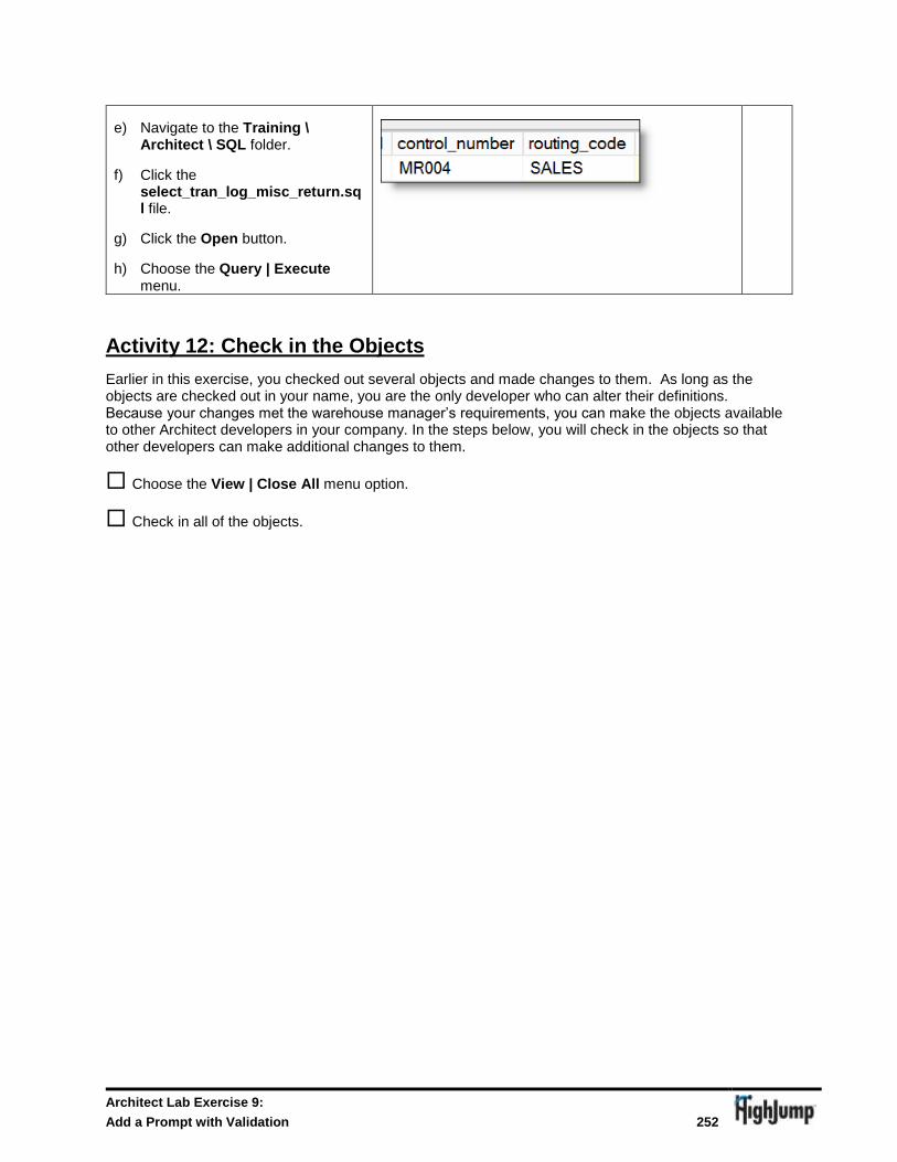
Architect Lab Exercise 9:
Add a Prompt with Validation 252
e) Navigate to the Training \ Architect \ SQL folder.
f) Click the select_tran_log_misc_return.sql file.
g) Click the Open button.
h) Choose the Query | Execute menu.
Activity 12: Check in the Objects
Earlier in this exercise, you checked out several objects and made changes to them. As long as the objects are checked out in your name, you are the only developer who can alter their definitions. Because your changes met the warehouse manager’s requirements, you can make the objects available to other Architect developers in your company. In the steps below, you will check in the objects so that other developers can make additional changes to them.
Choose the View | Close All menu option.
Check in all of the objects.

Architect Lab Exercise 10:
Function Keys 253
Architect Lab Exercise 10: Function Keys
Introduction In this exercise you will allow a user to press the F2 function key at the Label Quantity prompt in the Receipt from Production business process. Then you will tie logic to the F2 key so that the system does not print any labels if the user presses the F2 function key.
Background Information This exercise uses the Receipt from Production business process as a basis for all activities. In some warehousing environments, there is an attached production facility where the company manufactures the products. After the finished goods are produced, someone physically moves them from the production facility to the warehousing facility where they remain until they are shipped out of the warehouse. The Receipt from Production business process records the arrival of a finished good into the warehouse where the finished good was manufactured in an onsite production facility. The material handler places the finished good onto his fork, and the HighJump system directs him to move the finished good into an appropriate location in the warehouse.
The Receipt from Production business process gives the material handler the option of printing a simple item label that contains the item number and item description. The material handler can indicate that he doesn’t want any labels by entering a quantity of 0 at the label quantity prompt. The label printing logic occurs in several of the receiving processes.

Architect Lab Exercise 10:
Function Keys 254
Activity 1: Understand the Current Process
This activity demonstrates the Receipt from Production business process on the RF terminal. Follow the procedures below to see how the Receipt from Production process operates in the base application.
Log in to the Virtual Terminal as AMY / AMY / FAAMY.
Enter option 1 (the Receipts menu.)
Enter option 5 (the Receipt from Prod menu.)
Press the F2 key (switch) at the LP dialog.
Enter NNFG00000 at the Item Number dialog.
Enter 5 at the Eaches dialog.
Enter 1 at the Label Quantity dialog.
The system displays the LABEL ACTION FAILED because the label interface has not been set up in the training environments.
Type 0 at the Label Quantity dialog.
The system moves the inventory to the fork; loops back to the item prompt; and displays the F3:Done function key option. When the user presses the F3 function key on the LP (or Item) prompt, the system directs the user to move the inventory into an appropriate location in the warehouse.
Press the F3 key (Done) at the Item Number dialog.
Enter the suggested location at the Location dialog.
Press the Enter key at the Eaches dialog to accept the defaulted quantity.
If the system prompts for an LP, then type a unique license plate at the LP dialog.
Press the Enter key at the Transaction Complete dialog.
Press the F1 key until the system displays the menu dialog.

Architect Lab Exercise 10:
Function Keys 255
Activity 2: Understand the Requirements
This activity identifies the changes that the warehouse manager wants to make to the Receipt from Production business process.
The warehouse manager calls you on the phone. He explains that the users often do not print any labels during the process. They attempt to enter 0 at the label quantity prompt, but they often mistype the 0. Consequently, the system prints unwanted labels. The warehouse manager would like the system to default the label quantity prompt 1. However, he would like an easier way for the users to indicate that they don’t want any labels.
The two of you work together on a design, and you agree that the system will display an F2:NoLabel function key option on the label quantity prompt. When the user presses the F2:NoLabel function key on this screen, the system behaves as if the user entered a label quantity of 0. You agree that the system should display the label quantity prompt to the user in the following manner.
Lastly, since the label printing logic exists in multiple receiving processes, you and the warehouse manager agree that the F2:NoLabel logic will exist in all receiving processes.
Activity 3: Develop the Changes
In order to meet the warehouse manager’s requirements you must introduce the following changes to the Receipt from Production business process. 1. Display the F2:NoLabel on the label quantity screen 2. Allow the user to enter the F2 function key on the label quantity screen 3. Set the label quantity equal to zero if the user presses the F2 function key
The system already contains a base application process object which prompts for a label quantity and validates that the user-entered value is between 0 and 99. You will modify this process object to account for the above points. The graphic below shows the finished process object that you will create. The chart that follows gives a brief description of several lines.

Architect Lab Exercise 10:
Function Keys 256
1 Populates the SCR fields with label-quantity-related resources which the system will display on the screen. Initializes the SCR_OPTIONS field to an empty value. For additional details on this calculate action, please see the exercise titled Exercise 5: Display Text on the Reader.
2 Populates the SCR_OPTIONS field with the “F2:NoLabel” text. The system will eventually display this field on the screen.
3 Calls the Dialog process object. Because of the values set in line 1 and line 2, this process object prompts the user for a label quantity while displaying the F2:NoLabel text and then waits for the user to respond. For additional details on the Dialog process object, please see the exercise titled Exercise 5: Display Text on the Reader. If the user presses a function key, the system continues with line 4. If the user does anything other than a function key, the system continues with line 6.
4 Asks the question, “Did the user press the F2 function key?” If YES, then continue with line 5. If NO, then continue with line 13.
5 Populate the Label Quantity with a value of 0. Then continue with line 10.
6 Asks the question, “Did the user provide a value on the screen”
7 Populates the Label Quantity field with the user-entered value.
8 - 9 Asks the question, “Is the user-entered Label Quantity between 0 and 99”?
13 - 17 Builds error messages for actions that fail in other parts of the process object.

Architect Lab Exercise 10:
Function Keys 257
Earlier in this exercise you saw that the system contained a prompt for a label quantity. In order to add the F2:NoLabel logic, you must find this prompt in the Receipt from Production business process. Follow the procedures below to identify the label quantity prompt in Receipt from Production.
In Advantage Architect, double click WA in the Repository tab.
Choose the Define | Business Process menu option.
Double click the Receipt from Production node.
The system opens the definition of the business process object. The chart that follows gives a brief description of several lines.
Line Number Description
20 Prompts for a Quantity. This is a dialog-centric process object.
28 Calls the transaction process object.
30 Calls a process related to printing item labels.
32 Calls the log process object.
Using the naming conventions you learned in the exercise titled Exercise 7: Add a New Business Process, you can identify line 21 as the dialog-centric process object which prompts for a quantity. However, you not see any dialog-centric process objects with a standard name for a label quantity prompt. Here you have to look at the name on line 29 “Print Item Label” and make an educated guess that it contains a prompt for a label quantity. Follow the procedures below to continue hunting for the label quantity prompt in Receipt from Production.

Architect Lab Exercise 10:
Function Keys 258
Click the Action Name column of line 30 (Call…Print Item Label) to bring focus.
Double click the Action Name column of line 30 (Call… Print Item Label).
The system opens the definition of the process object. The chart that follows gives a brief description of several lines.
Line Number Description
1 Prompts for a Label Quantity. This is a dialog-centric process object. The name is non-standard because it is used in multiple business processes.
2 Asks the question, “Is the Label Quantity field (entered by the user) = 0?”
7 Sends a label request to the Bartender label printing software.
You are still hunting for the dialog-centric process object for the label quantity. However, this process object does not contain any calls to objects that follow the standard naming conventions for dialog-centric process objects. In a minute, you will see that line 1 is indeed a dialog-centric process object. However, it does not follow the standard naming conventions because it is used in multiple business processes. Here you have to look at the name on line 1 “Label Quantity” and make an educated guess that it contains a prompt for a label quantity. Follow the procedures below to continue hunting for the label quantity prompt in Receipt from Production.
Click the Action Name column of line 1 (Call…Label Quantity) to bring focus.
Double click the Action Name column of line 1 (Call… Label Quantity).

Architect Lab Exercise 10:
Function Keys 259
The system opens the definition of the process object. The chart that follows gives a brief description of several lines.
Line Number Description
1 Populates the SCR fields with label-quantity-related resources which the system will display on the screen. For additional details on this calculate action, please see the exercise titled Exercise 5: Display Text on the Reader.
2 Calls the Dialog process object. Because of the values set in line 1, this process object prompts the user for a label quantity and then waits for the user to respond. For additional details on the Dialog process object, please see the exercise titled Exercise 5: Display Text on the Reader.
3 Asks the question, “Did the user provide a value on the screen”
4 Populates the Label Quantity field with the user-entered value.
5 – 6 Asks the question, “Is the user-entered Label Quantity between 0 and 99”?
10 - 14 Builds error messages for actions that fail in other parts of the process object.
Based on lines 1 and 2, this process object prompts for a Label Print Quantity. The format of this process object conforms to the standards for a dialog-centric process object. This is the process object you must change to display the F2:NoLabel text on the screen and to allow the user to enter the F2 function key.
In the exercise titled Exercise 5: Display Text on the Reader, you learned that the SCR_OPTIONS field holds the function key text that the system will eventually display on the screen. Line 1 of this process object is the screen text calculate action, and it initializes the SCR_OPTIONS field to an empty value. The development standards indicate that the function key text is defined in its own calculate action separate from the screen text calculate action. In order to display the F2:NoLabel text on the screen, you

Architect Lab Exercise 10:
Function Keys 260
must create a function key calculate action that populates the SCR_OPTIONS field. The base application contains several function key calculate actions. Rather than build the new calculate action from scratch, you will copy an existing one and modify it for the F2:NoLabel text. Perform the following procedures to build a function key calculate actions that populates the SCR_OPTIONS field with the “F2:NoLabel” text.
Choose the Define | Calculate menu option.
Right click the ScrOpt: F2:Switch node.
Choose the Copy As menu option.
The system opens the Copy As window.
Type ScrOpt: F2:NoLabel in the New Object Name edit box.
Click the OK button.
The system creates a new calculate action that should look like the following graphic.
In this calculate action, the system concatenates the current value of the SCR_OPTIONS field with the “F2:Switch” text. Then it appends a trailing space to the string. The first line of the calculate action is the only component that needs to change. Follow the procedures below to swap the “F2:Switch” text with the “F2:NoLabel” text.
Click the Operand2 cell of line 1 (SCR_OPTIONS = ScrOpt: F2:Switch) to bring focus.
Double click the Operand2 cell of line 1 (SCR_OPTIONS = ScrOpt: F2:Switch).

Architect Lab Exercise 10:
Function Keys 261
The system opens the definition of the resource.
Choose the File | Copy As menu option.
The system displays the Copy As window.
Enter ScrOpt: F2:NoLabel in the New Object Name edit box.
Click the OK button.
Enter F2:NoLabel in the Text edit box.
Choose the File | Save menu option.
The finished resource should look like the following screenshot.
.

Architect Lab Exercise 10:
Function Keys 262
You have created a resource which contains the F2:NoLabel text. However, the resource alone is not enough to cause the system to display the text. You must also set the SCR_OPTIONS field equal to this resource. Follow the procedures below to set the SCR_OPTIONS field equal to the resource in the function key calculate action.
Click the ScrOpt: F2:NoLabel tab (calculate) along the top of the tool.
Click the Operand2 cell of line 1 (SCR_OPTIONS = ScrOpt: F2:Switch) to bring focus.
Choose ScrOpt: F2:NoLabel in the Operand 2 drop down box.
Choose the File | Save menu option.
The finished calculate action should look like the following graphic.
You have created a function key calculate action which populates the SCR_OPTIONS field with the “F2:NoLabel” text. However, the system will still not display it on the label quantity screen. In order for the system to display the text on the label quantity screen, you must include this calculate action in the dialog-centric process object for the label quantity. Follow the procedures below to include this calculate action in the label-quantity-related dialog-centric process object which you identified earlier.
Click the Label Quantity tab (process object) along the top of the tool.
Choose the Version Control | Check Out menu option.
Click the left-most column of line 2 (Call…Dialog) to highlight the row.
Click the Insert Before button.
Choose Calculate in the Type drop down box.
Choose ScrOpt: F2:NoLabel in the Action Name drop down box.
Choose the File | Save menu option.
The process object should look like the following graphic. The chart that follows gives a brief description of several lines.
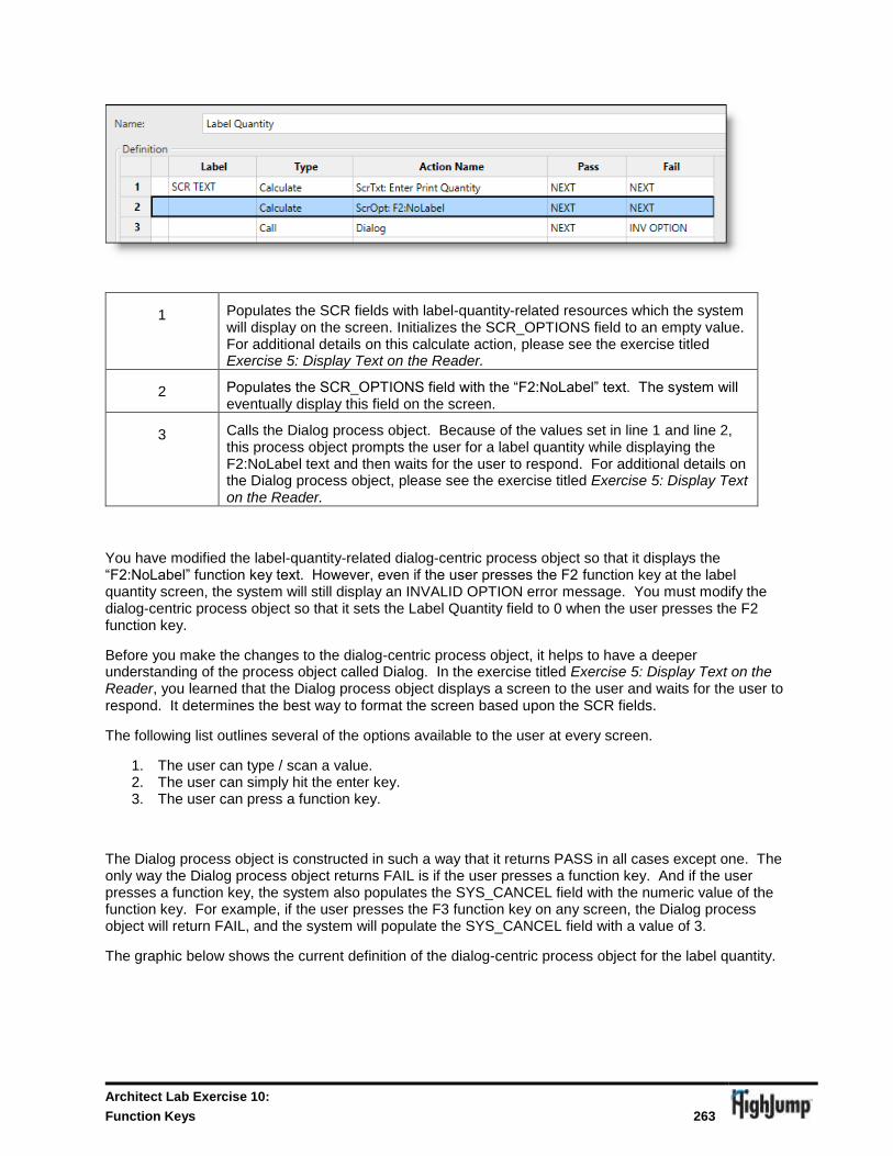
Architect Lab Exercise 10:
Function Keys 263
1 Populates the SCR fields with label-quantity-related resources which the system will display on the screen. Initializes the SCR_OPTIONS field to an empty value. For additional details on this calculate action, please see the exercise titled Exercise 5: Display Text on the Reader.
2 Populates the SCR_OPTIONS field with the “F2:NoLabel” text. The system will eventually display this field on the screen.
3 Calls the Dialog process object. Because of the values set in line 1 and line 2, this process object prompts the user for a label quantity while displaying the F2:NoLabel text and then waits for the user to respond. For additional details on the Dialog process object, please see the exercise titled Exercise 5: Display Text on the Reader.
You have modified the label-quantity-related dialog-centric process object so that it displays the “F2:NoLabel” function key text. However, even if the user presses the F2 function key at the label quantity screen, the system will still display an INVALID OPTION error message. You must modify the dialog-centric process object so that it sets the Label Quantity field to 0 when the user presses the F2 function key.
Before you make the changes to the dialog-centric process object, it helps to have a deeper understanding of the process object called Dialog. In the exercise titled Exercise 5: Display Text on the Reader, you learned that the Dialog process object displays a screen to the user and waits for the user to respond. It determines the best way to format the screen based upon the SCR fields.
The following list outlines several of the options available to the user at every screen.
1. The user can type / scan a value. 2. The user can simply hit the enter key. 3. The user can press a function key.
The Dialog process object is constructed in such a way that it returns PASS in all cases except one. The only way the Dialog process object returns FAIL is if the user presses a function key. And if the user presses a function key, the system also populates the SYS_CANCEL field with the numeric value of the function key. For example, if the user presses the F3 function key on any screen, the Dialog process object will return FAIL, and the system will populate the SYS_CANCEL field with a value of 3.
The graphic below shows the current definition of the dialog-centric process object for the label quantity.

Architect Lab Exercise 10:
Function Keys 264
Here, because of the values set in line 1, the Dialog process object prompts for a Label Quantity. If the user presses any function key, the Dialog process object returns FAIL and the system continues by building an error message in line 11. This behavior needs to change in order to meet the warehouse manager’s requirements.
Since this screen will now display the F2:NoLabel text on the screen, it needs to allow the user to press the F2 function key. The FAIL branch on the Dialog process object needs to change, but the system also needs to ask the question, “Did the user press the F2 function key?” The system can ask this question through a compare action that compares the SYS_CANCEL field with a constant value of 2. There are several compare actions in the base application that do this. Rather than build the new compare action from scratch, you will copy an existing one and modify it for the F2:NoLabel function key. Perform the following procedures to build a compare action that asks the question, “Did the user press the F2 function key?”
Choose the Define | Compare menu option.
Right click the <F2:Switch>? node.
Choose the Copy As menu option.
The system displays the Copy As window.
Type <F2:NoLabel>? in the Name edit box.
Click the OK button.

Architect Lab Exercise 10:
Function Keys 265
There is nothing to modify on the new compare action. It now has an appropriate name, and it checks if the user pressed the F2 key. The finished compare action should look like the following graphic.
This compare action compares the SYS_CANCEL field with a constant value of 2. It does exactly what it needs to do for the F2:NoLabel logic. Essentially, the <F2:NoLabel>? compare action and the <F2:Switch>? compare action are identical except for their names. In theory, only one would be needed in the base application. However, the base application utilizes multiple objects, with context specific names, to make the application a little more readable.
You have built a compare action which asks the question, “Did the user press the F2 function key?” However, the system will still display an error message if the user presses the F2 function key on the label quantity screen. In order for the system to accept the F2 function key, you must include the compare action in the dialog-centric process object and modify some of the PASS / FAIL branches. Follow the procedures below to add the compare action to the dialog-centric process object.
Click the Label Quantity tab (process object) along the top of the tool.
Enter VERIFY in the Label edit box of line 4 (compare…Dialog Field = “”?)
Choose VERIFY in the Pass edit box of line 3 (call…Dialog)
Choose NEXT in the Fail edit box of line 3 (call…Dialog)
Click the left-most column of line 3 (Call…Dialog) to highlight the row.
Click the Insert After button.
Choose Compare in the Type drop down box.
Choose <F2:NoLabel>? in the Action Name drop down box.
Choose INV OPTION in the Fail edit box.
Choose the File | Save menu option.
The process object should look like the following graphic.

Architect Lab Exercise 10:
Function Keys 266
The process object is not complete. The system now checks if the user pressed the F2 function key. However, it performs no special logic if the user did choose the F2 function key. Follow the procedures below to set the Label Quantity field equal to 0 if the user presses the F2 function key.
Right click the Label Quantity tab (process object) along the top of the tool.
Choose the Close All But This menu option.
Click the left-most column of line 4 (Compare…<F2:NoLabel>?) to highlight the row.
Click the Insert After button.
Choose Calculate in the Type drop down box.
Click the Asterisk button on the right side of the Action Name drop down box.
Chose the Calculate Action menu option.
Enter Label Quantity = 0 In the Action Name edit box.
Click the Checkmark button on the right side of the Action Name drop down box.
After you click the checkmark button, the system creates a new calculate action with the given name. Additionally, the system creates a new tab for the new calculate action along the top of the tool.
Choose SUCCESS in the Pass edit box.
Choose SUCCESS in the Fail edit box.
Choose the File | Save menu option.

Architect Lab Exercise 10:
Function Keys 267
The finished process object should look like the following graphic. The chart that follows gives a brief description of several lines.
1 Populates the SCR fields with label-quantity-related resources which the system will display on the screen. Initializes the SCR_OPTIONS field to an empty value. For additional details on this calculate action, please see the exercise titled Exercise 5: Display Text on the Reader.
2 Populates the SCR_OPTIONS field with the “F2:NoLabel” text. The system will eventually display this field on the screen.
3 Calls the Dialog process object. Because of the values set in line 1 and line 2, this process object prompts the user for a label quantity while displaying the F2:NoLabel text and then waits for the user to respond. For additional details on the Dialog process object, please see the exercise titled Exercise 5: Display Text on the Reader. If the user presses a function key, the system continues with line 4. If the user does anything other than a function key, the system continues with line 6.
4 Asks the question, “Did the user press the F2 function key?” If YES, then continue with line 5. If NO, then continue with line 13.
5 Populate the Label Quantity with a value of 0. Then continue with line 10.
6 Asks the question, “Did the user provide a value on the screen”
7 Populates the Label Quantity field with the user-entered value.
8 - 9 Asks the question, “Is the user-entered Label Quantity between 0 and 99”?
13 - 17 Builds error messages for actions that fail in other parts of the process object.

Architect Lab Exercise 10:
Function Keys 268
You have created the placeholder for the calculate action which sets the Label Quantity equal to 0. Next you need to define its details. Follow the procedures below to define the content of the calculate action.
Click the Label Quantity = 0 tab (calculate action) along the top of the tool.
Click the Insert After button.
Choose Equals in the Operation selection box.
Choose Label Quantity in the Result drop down box.
Click the Asterisk button on the right side of the Operand 1 drop down box.
Chose the Constant - Numeric menu option.
Enter 0 in the Operand 1 edit box.
Choose the File | Save menu option.
The finished calculate action should look like the following graphic.
You have modified the dialog-centric process object for the label quantity prompt so that it displays the “F2:NoLabel” text. And you have modified the process object so that it sets the Label Quantity field to 0 when the user presses the F2 function key. You have modified all of the necessary objects to meet the requirements of the warehouse manager.
Activity 4: Compile and Activate the Changes
At this point you have modified several objects to meet the requirements dictated by the warehouse manager. However, if you run the process on the Virtual Terminal, you will see that your changes have not taken effect. In order for your changes to take effect, you must first compile the application and then activate the application. The procedures below are very generic. If you need additional details on how to compile and activate the application, please see the activity titled Compile and Activate the Changes in the exercise titled Exercise 1: Introduction to Advantage Architect.

Architect Lab Exercise 10:
Function Keys 269
Compile the application
Activate the application

Architect Lab Exercise 10:
Function Keys 270
Activity 5: Test the Changes
The chart below outlines the various test cases that must be validated. Each test case defines an action you must take, and it defines the expected outcome based on the requirements. If a given test case does not yield the expected outcome, then review the steps from the previous activity. It is likely that you either missed a step or performed a step incorrectly. The test cases do not detail every keystroke. You need to use the knowledge you gained in the first activity of this exercise in order to test the scenarios.
Starting the Receipt from Production Business Process
From the Main Menu choose Option 1, Option 5
Press the F2 key (switch) at the LP dialog.
Enter NNFG00000 at the Item Number dialog.
Test Case Expected Outcome Pass / Fail
Enter a Quantity at the Eaches dialog.
System displays the Label Quantity dialog which includes the F2:NoLabel text on the bottom of the dialog.
Press the F1 key at the Label Quantity dialog.
System displays INVALID OPTION error message.

Architect Lab Exercise 10:
Function Keys 271
Press the F3 key at the Label Quantity dialog.
System displays INVALID OPTION error.
Enter 7 at the Label Quantity dialog.
System displays LABEL ACTION FAILED message.
Type 0 at the Label Quantity dialog.
System advances to the Item Number dialog.

Architect Lab Exercise 10:
Function Keys 272
(Note: Before you run the next test case, you should press the F3:Done key and then follow then follow the instructions on the remainder of the screens.)
Press the F2 key at the Label Quantity dialog.
System advances to the Item Number diaF3log.
(Note: before you continue in the exercise, you should press the F3:Done key and then follow then follow the instructions on the remainder of the screens..)
Activity 6: Check in the Objects
Earlier in this exercise, you checked out several objects and made changes to them. As long as the objects are checked out in your name, you are the only developer who can alter their definitions. Because your changes met the warehouse manager’s requirements, you can make the objects available to other Architect developers in your company. In the steps below, you will check in the objects so that other developers can make additional changes to them.
Choose the View | Close All menu option.

Architect Lab Exercise 10:
Function Keys 273
Check in all of the objects.

Architect Lab Exercise 11:
Display a List 274
Architect Lab Exercise 11: Display a List
Introduction
In this exercise you will add a new dialog to the Order Picking process which displays a list of pick areas to the user. On this dialog the user will choose an entry from the list instead of manually scanning the pick area.
Background Information This exercise uses the Order Picking business process as a basis for all activities. When a customer (like Target or Walmart) wants to purchase some of the inventory in the warehouse, the customer will place an order with the company that manages the warehouse. That order passes through a couple computer systems and eventually makes its way to the HighJump system. Eventually, the HighJump system will direct a material handler to execute the order through an RF reader. The material handler finds the inventory in the warehouse associated with the order and places it into some sort of shippable container which eventually is shipped to the customer. The material handler uses the Order Picking business process to find the inventory in warehouse and place it into a shippable container.
The concept of a pick area is also central to this exercise. A pick area is a collection of locations where the same method of picking is utilized. For example, sometimes material handlers will pick an entire pallet of a product. Sometimes they will pick a case of a product. And other times, they will pick a quantity of 1. The rules for picking a pallet, a case, and an each are likely quite different from one another. Consequently, warehouses are laid out in such a way that full pallet picks take place in a separate physical area from the case picks. And the same is true for the each picks. The locations where a material handler picks full pallets of product is called a pallet pick area. The locations where a material handler picks a case of product is called a case pick area. And similarly with the each pick area.
This exercise emphasizes the concept of lists. The following online lesson introduces the list concept. Additionally, the lessons introduce records which are used when creating lists.
1. Open the Advantage Architect online course.
2. Review the Lists and List Actions topic.
3. Review the Create a Record topic.

Architect Lab Exercise 11:
Display a List 275
Activity 1: Understand the Current Process
This activity demonstrates the Order Picking business process on the RF terminal. Follow the procedures below to see how the Order Picking process operates in the base application.
Log in to the Virtual Terminal as AMY / AMY / FAAMY.
Enter option 4 (the Order Pick menu.)
Enter option 1 (the Order Picking menu.)
The system prompts for a pick area.
The pick area screen is the only relevant prompt. There is no need to continue any further.
Press the F1 key until the system displays the main menu.

Architect Lab Exercise 11:
Display a List 276
Activity 2: Understand the Requirements
This activity identifies the changes that the warehouse manager wants to make to the Order Picking business process.
The warehouse manager calls you on the phone. He explains that the users manually enter the pick area in the Order Picking process. They often mistype the value, and the system forces them to enter it a second or a third time. The system validates the entry against a database table, so there is no risk of bad data. The warehouse manager indicates that it is more a point of frustration than anything else. He would like a better way of entering the pick area on the terminals.
The two of you work together on a design, and you agree that the best way to solve the problem is to allow the user to choose the pick area from a list of valid entries. However, you want to retain the ability to manually enter a pick area. You agree to add an F8:LST function key option to the bottom of the pick area screen. If the user presses the F8 function key, the system displays a new screen with a list of valid pick areas. You agree that the system should display the pick area screen and the list screen to the user in the following manner.
F8

Architect Lab Exercise 11:
Display a List 277
Activity 3: Develop the Changes
In order to meet the warehouse manager’s requirements you must introduce the following changes to the Order Picking business process. 1. Display the F8:LST function key option on the pick area screen 2. Allow the user to press the F8 function key on the pick area screen 3. Display a list of pick areas if the user presses the F8 function key.
Ultimately you will build a process object which looks like the following graphic. The chart that follows gives a brief description of several lines.
Line Number Description
20 Populates the fields used by the Dialog “black box”.
21 Populates the SCR_OPTIONS field with “F8:LST” text. This is used by the Dialog “black box” on line 22.
22 Calls the Dialog “black box” which displays the standard pick area screen to the user.
23 Asks the question, “Did the user press the F1 function key?” (on the standard pick area prompt screen.)
24 Asks the question, “Did the user press the F8 function key?” (on the standard pick area prompt screen.)
25 Populates the SCR_OPTIONS with an empty value. This is used by the Dialog “black box” on line 29.
26 Clear the contents of the Dialog List.
27 Retrieve the pick area information from the database and store it in an Architect list.
28 Populates the Dialog Type field with “LIST”. This is used by the Dialog “black box” on line 29.

Architect Lab Exercise 11:
Display a List 278
29 Calls the Dialog “black box” which displays the list of pick areas to the user based upon the contents of the Dialog List.
Earlier in this exercise you saw that the system prompted for a pick area in the Order Picking process. Before you can change the logic, you first must find the process object which contains the pick area prompt. The process object is shared among multiple business processes and it is buried within a component related to interleaving. For these reasons, the manual simply gives you the name of the process object instead of drilling into it from the top-level business process.
In Advantage Architect, double click WA in the Repository tab.
Choose the Define | Process Object menu option.
Double click the Interleave Dispather – Picking – Pick Area node.
The system opens the definition of the process object. The chart that follows gives a brief description of several lines.
Line Number Description
20 Populates the 10 fields used by the Dialog “black box”.
21 Calls the Dialog “black box” which displays a screen to the user.
22 Asks the question, “Did the user press the F1 function key?”
23 Asks the question, “Did the user enter an empty value?”
24 Populate the Pick Area field with the value entered by the user.
This is the process object you will modify to account for the listing logic. In order to meet the requirements of the warehouse manager, you must display the F8:LST function key text on the pick area screen. This concept was discussed in detail in the exercise titled Exercise 9: Function Keys. The base

Architect Lab Exercise 11:
Display a List 279
application contains a calculate action which populates the SCR_OPTIONS field with the “F8:LST” text. Rather than creating a new calculate action, you will include an existing one in the process object. Follow the procedures below to display the “F8:LST” text on the pick area screen.
Choose the Version Control | Check Out menu option.
Click the left-most column of line 21 (Call…Dialog) to highlight the row.
Click the Insert Before button.
Choose Calculate in the Type drop down box.
Choose ScrOpt: F8:Lst in the Action Name drop down box.
Choose the File | Save menu option.
The process object should look like the following graphic.
Now the system will display “F8:LST” on the screen. But that is only part of the solution. In its current state, the system will display an INVALID OPTION error message if the user presses the F8 key. You must modify the process object so that F8 is a valid entry. This concept was discussed in detail in the exercise titled Exercise 9: Function Keys. The base application contains a compare action which compares the SYS_CANCEL field with a constant of 8. Rather than creating a new compare action, you will include an existing one in the dialog-centric process object.
Click the left-most column of line 23 (Compare…<F1:Cancel>?) to highlight the row.
Click the Insert After button.
Choose Compare in the Type drop down box.
Choose <F8:Lst>? in the Action Name drop down box.
Choose INV OPTION in the Fail drop down box.
Choose NEXT in the Fail drop down box of line 23 (Compare…<F1:Cancel>?)

Architect Lab Exercise 11:
Display a List 280
Choose the File | Save menu option.
The process object should look like the following graphic. The chart that follows gives a brief description of several lines.
Line Number Description
20 Populates the 10 fields used by the Dialog “black box”.
21 Populates the SCR_OPTIONS field with “F8:LST” text.
22 Calls the Dialog “black box” process object which displays a screen to the user.
23 Asks the question, “Did the user press the F1 function key?”
24 Asks the question, “Did the user press the F8 function key?”
25 Asks the question, “Did the user enter an empty value?”
26 Populate the Pick Area field with the value entered by the user.
You have displayed “F8:LST” on the pick area screen. And you have allowed the user to press the F8 function key on that screen. Next you will tie functionality to the F8 function key. According to the requirements, you must display a list of valid pick areas to the user when he presses the F8 function key. And you must allow him to choose one of the pick areas from the list. Most of the listing functionality is managed within the Dialog “black box.” As a developer you are responsible for populating an Architect List with the data that should be displayed on the screen, and the “black box” will do most of the remaining work.
There are several business processes which present lists to the user. Rather than building a new set of objects for the pick area list, you will copy/paste existing objects and then modify them accordingly. Follow the procedures below to copy some existing list functionality from the QC Hold business process and paste it into the current process.
Choose the Define | Process Object menu option.
Double click the List ASN Clients node.

Architect Lab Exercise 11:
Display a List 281
Click the left-most column of line 2 (Calculate…SCR_OPTIONS = “”) to highlight the row.
Press and hold the shift key on the keyboard.
Click the left-most column of line 6 (Call…Dialog) to highlight multiple rows.
Release the shift key on the keyboard.
Right click anywhere in the grid of the process object.
Choose the Copy menu option.
Click the Interleave Dispather – Picking – Pick Area tab (process object) along the top of the tool.
Right click the left-most column of line 25 (Compare…Dialog Field = “”?) to highlight the row
Choose the Paste menu option.
Choose the File | Save menu option
The process object should look like the following diagram. The chart that follows gives a brief description of several lines.
Line Number Description
24 Asks the question, “Did the user press the F8 function key?” (on the standard pick area prompt screen.)
25 Populates the SCR_OPTIONS with an empty value. This is used by the Dialog “black box” on line 29.
26 Clear the contents of the Dialog List.
27 Retrieve client-related information from the database and store it in an Architect list.
28 Populates the Dialog Type field with “LIST”. This is used by the Dialog “black box” on line 29.
29 Calls the Dialog “black box which displays the list of pick areas to the user.

Architect Lab Exercise 11:
Display a List 282
Most of the lines which you pasted into the process are generic and can be reused in any process object that displays a list to the user. The only line that needs to change is line 27. Line 27 current populates an Architect list with ASN client-related information. You will replace this line with one that populates an Architect list with pick area information. Follow the procedures below to create a database action and a process object wrapper specific to the pick area example.
Choose the Define | Database (Actions) menu option.
Choose the File | New menu option
Enter List PKA Pick Areas in the Name edit box.
Enter the following query into the Statement multi-line edit box.
STATEMENT ( SELECT ROW_NUMBER () OVER (ORDER BY pick_area) as rn, SUBSTRING (pick_area, 1, 15),
pick_area FROM t_pick_area WHERE wh_id = :Warehouse ID: ) RETURNS ( :Sequence: , :Display List: , :Dialog Field: )
Choose Dialog List in the List drop down box.
Choose the File | Save menu option.
The finished database action should look like the following graphics.

Architect Lab Exercise 11:
Display a List 283
Best practice indicates that you should test the syntax of the database action before making any additional changes.
Click the Test button on the right side of the window.
Enter the machine name of the database server in the Server Name edit box.
Enter AAD in the Database Name edit box.
Use the SQL Server section of the login.txt file to complete the remaining edit boxes.
Click the Connect button.
The system displays a window which allows you to enter all of the fields referenced in the query.
Enter 01 in the Value edit box.
Click the OK button.
The system shows the results of the query.

Architect Lab Exercise 11:
Display a List 284
This query returns 11 total rows. Each row corresponds with a list element that will eventually appear on the screen. The first column (rn) is the row number which will display on the screen. The second column (Column1) is list option text that will display on the screen. The third column (pick_area) is the value that is used when the user selects an option from the list.
You have built a new database action which populates the Dialog List with a set of records. However, according to the standards, every database action should have a corresponding process object wrapper. Follow the procedures below to create a process object wrapper for the new database action.
Choose the Define | Process Object menu option.
Right click the DBUpd ORM Sts w/Order node.
Choose the Copy As menu option.
The system displays the Copy As window.
Enter DBList PKA Pick Areas in the Name edit box.
Click the OK button.
The system creates a new process object.

Architect Lab Exercise 11:
Display a List 285
Choose List PKA Pick Areas in the Action Name drop down box of line 3 (Database…Upd ORM Sts w/Order)
Click the left-most column of line 1 (Compare…Order Number = “”?) to highlight the row.
Click the Delete button.
Click the left-most column of line 1 (Compare…Status = “”?) to highlight the row.
Click the Delete button.
Choose the File | Save menu option.
The finished process object wrapper should look like the following graphic. The chart that follows gives a brief description of several lines.
Line Number Description
1 Populates an Architect List with the pick area data that should be displayed in a list format.

Architect Lab Exercise 11:
Display a List 286
2 - 3 Handles the case when the database action fails.
5 Builds an error message, which the system will eventually display to the user.
6 - 7 Builds a log message and sends it to the HighJump platform log.
You have built a database action which populates an Architect list with the pick area data that will appear on the screen. And you have built a corresponding process object wrapper. Next you will include the wrapper in the order picking process.
Click the Interleave Dispather – Picking – Pick Area tab (process object) along the top of the tool.
Choose DBList PKA Pick Areas in the Action Name drop down box of line 27 (Call…DBList ASN Client)
Choose the File | Save menu option.
The finished process object should look like the following graphic. The chart that follows gives a brief description of several lines.
Line Number Description
24 Asks the question, “Did the user press the F8 function key?” (on the standard pick area prompt screen.)
25 Populates the SCR_OPTIONS with an empty value. This is used by the Dialog “black box” on line 29.
26 Clear the contents of the Dialog List.
27 Retrieve the pick area information from the database and store it in an Architect list.
28 Populates the Dialog Type field with “LIST”. This is used by the Dialog “black box” on line 29.
29 Calls the Dialog “black box which displays the list of pick areas to the user.

Architect Lab Exercise 11:
Display a List 287
In summary, you made the following changes in Architect:
You added the F8:LST text to the Pick Area screen
You allowed the user to press the F8 key on the Pick Area screen
You retrieved the pick area information from the database and stored it in an Architect list.
You called the Dialog “black box” which will display the contents of the list on a screen.
Activity 4: Compile and Activate the Changes
At this point you have modified several objects to meet the requirements dictated by the warehouse manager. However, if you run the process on the Virtual Terminal, you will see that your changes have not taken effect. In order for your changes to take effect, you must first compile the application and then activate the application. The procedures below are very generic. If you need additional details on how to compile and activate the application, please see the activity titled Compile and Activate the Changes in the exercise titled Exercise 1: Introduction to Advantage Architect.
Compile the application
Activate the application

Architect Lab Exercise 11:
Display a List 288
Activity 5: Test the Changes
The chart below outlines the various test cases that must be validated. Each test case defines an action you must take, and it defines the expected outcome based on the requirements. If a given test case does not yield the expected outcome, then review the steps from the previous activity. It is likely that you either missed a step or performed a step incorrectly. The test cases do not detail every keystroke. You need to use the knowledge you gained in the first activity of this exercise in order to test the scenarios.
Starting the Order Picking Business Process
From the Main Menu choose Option 4, Option 1
Test Case Expected Outcome Pass / Fail
Launch the Order Picking business process as outlined above.
System advances to the pick area screen which contains an F8:LST option.
Enter ABC at the Pick Area screen.
System displays INVALID PICK AREA error.

Architect Lab Exercise 11:
Display a List 289
Choose the F7 key at the Pick Area screen.
System displays INVALID OPTION error.
Enter PALLET at the Pick Area dialog.
System advances to the order number screen.
Choose the F8 key at the Pick Area screen.
System displays a list of pick areas.

Architect Lab Exercise 11:
Display a List 290
Choose the F8 key at the Pick Area List screen
System advances to the next page of pick areas.
Choose the F4 key at the Pick Area List screen.
System displays the previous page of pick areas.
Enter 99 at the Pick Area List screen.
System displays INVALID OPTION message.

Architect Lab Exercise 11:
Display a List 291
Enter 4 (Case) at the Pick Area List screen.
System advances to the order number screen.
Activity 6: Check in the Objects
Earlier in this exercise, you checked out several objects and made changes to them. As long as the objects are checked out in your name, you are the only developer who can alter their definitions. Because your changes met the warehouse manager’s requirements, you can make the objects available to other Architect developers in your company. In the steps below, you will check in the objects so that other developers can make additional changes to them.
Choose the View | Close All menu option.
Check in all of the objects.

Admin Lab Exercise 12:
Advantage Architect Applications 292
Admin Lab Exercise 12: Advantage Architect Applications
Introduction This exercise consists of the following activities:
1. Export an Advantage Architect Application
2. Import an Advantage Architect Application
3. Compile and Activate an Advantage Architect Application
4. Test the Changes
5. Restore the Original Application
Background Information Advantage Architect is the development tool created by HighJump Software which is used to modify the business processes that run on the RF terminals.
Most HighJump customers have three fully functional instances of the HighJump system. One instance is the system of record. This instance is called the “live” environment or the production environment. The second instance is a development environment where changes can be developed. The third instance is a test environment where system testing takes place.
Making changes to the HighJump system is standard practice in most warehouses. Sometimes the end users ask for enhancements; sometimes a business process does not work according to the design; and sometimes the warehouse operation changes. All of these cases demand a change to the HighJump system.
These changes are typically made in the development environment. Then those changes are copied to the test environment where a different team validates that they work as expected. Then, lastly, the changes are copied to the production environment. The process of copying changes from one environment to another is called a “promotion” or a “release”. As far as Advantage Architect is concerned, a promotion involves exporting the Architect application out of one environment and then importing / compiling / activating it in another environment.
HighJump has a recommended methodology for managing releases and promotions. The recommendations are documented in a “Best Practice” file in the desktop folder. You can also obtain the document by contacting the HighJump Support Team.

Admin Lab Exercise 12:
Advantage Architect Applications 293
Activity 1: Export an Advantage Architect Application
Situation: The daily operations in the warehouse have changed, and the warehouse manager has requested a handful of changes to the business processes. Your team has made the corresponding changes to Advantage Architect in the development environment. Now you are ready to promote those changes to a test environment so that the warehouse supervisors can test the new functionality.
Procedures: The promotion process involves an export out of the development environment and an import / compile / activate into the test environment. The procedures below demonstrate how to export the WA Advantage Architect application as part of a promotion process. (They do not demonstrate how to import the application into the next environment.)
First, you will create a folder structure on the desktop which will hold the exported application. In the real-world, this folder would likely be on the network. Since this scenario is in the context of promoting an application from one environment to another, you will create a folder name that contains a sequential release number. The folder structure you create will look like similar to the following screenshot.
Right-click anywhere on the Desktop.
Choose the New | Folder menu option.
Enter My Releases in the edit box for the name of the folder.
Double click the My Releases folder you just created in order to open it.
Right click anywhere in the panel on the right.
Choose the New | Folder menu option.
Enter Release 01 in the edit box for the name of the folder.
The folder structure should look like the following snapshot.

Admin Lab Exercise 12:
Advantage Architect Applications 294
The folder is created. Next you will launch the Advantage Architect tool and log into it.
Choose the Start | All Programs | HighJump Software | Advantage Architect menu option.
The system opens the Connect to Application Repository window. A repository is a SQL Server / Oracle database that houses all of the Advantage Architect objects for the Advantage Architect applications. In this window you instruct the system where the repository is located.
Enter (local) in the Server Name edit box.
Enter REPOS in the Database Name edit box.
Select the Use SQL Server Authentication radio button.
Use the Architect section of the login.txt file in the folder on the desktop to populate the Login and Password edit boxes of the Connection dialog.
Click the Connect button.
The system displays the Application Login window.
Type your name in the User Name edit box. (There is no validation on this entry.)
Click the OK button.

Admin Lab Exercise 12:
Advantage Architect Applications 295
The system opens the Advantage Architect tool.
Next you will export the WA application from Advantage Architect into the folder you created above.
Choose the File | Export | Export Application menu.
The system opens the Export Application window.
Choose WA in the Application drop-down list.
Click the ellipsis button to the right of the Export Folder edit box.
Navigate to the Desktop \ My Releases \ Release 01 folder.
Click the OK button.
The Export Application window should look like the following graphic.

Admin Lab Exercise 12:
Advantage Architect Applications 296
Click the OK button.
As Advantage Architect exports the application, it displays the status in the Output Window near the bottom of the screen.
When the export is completed successfully, the system displays the Completed dialog.
Click the OK button.
In Windows Explorer, view the contents of the Desktop \ My Releases \ Release 01 folder.
The system has created a set of XML files in the folder.

Admin Lab Exercise 12:
Advantage Architect Applications 297
At this point, you could leave the XML files in their current state. However, it is often easier to deal with a single ZIP file instead of multiple XML files. This is especially true if you need to promote an Advantage Architect application from one environment to another. Follow the procedures below to zip the XML files into a single ZIP file.
Press Control + A to select all of the files in the Release 01 folder
Right-click any of the selected files.
Choose the Send To | Compressed (Zipped) Folder menu option.
The system creates a zipped file amongst the other XML files. The name of your zipped file may be different than the one in the diagram.
Select all of the files in the folder EXCEPT for the zipped file you just created.
Press the Delete key on the keyboard.
The system presents a window confirming that you want to delete the files.
Click the Yes button.

Admin Lab Exercise 12:
Advantage Architect Applications 298
The system deletes all of the XML files and leaves the zip file in the folder. The name of your zipped file may be different than the one in the diagram.
The name of the zip file should indicate the application name (WA) and the release number (release 01). This is to prevent any confusion if the zip file becomes separated from the actual release folder.
Rename the ZIP file to wa_architect_release_01.zip
The contents of the folder should look like the following screenshot.
Every release folder should include a document that describes the changes included in the release. This document is called the release notes. Usually, the developers who make the changes will create the document. The “Best Practices” document contains a recommended template for the release notes. In this example, you will create a very simple set of release notes.
Open Notepad
Add the following lines (or something similar) to the new document. ================================= RELEASE 01 ================================= 1. Contains the WA base training application.
Notepad should look like the following graphic.

Admin Lab Exercise 12:
Advantage Architect Applications 299
Choose the File | Save menu option.
Click the Desktop link in the panel on the left.
Navigate to the My Releases | Release 01 folder.
Enter release_notes_for_release_01 in the File Name edit box.
Click the Save button.
Choose the File | Exit menu option.
The system creates the release notes in the same folder as the zipped WA application.
In this activity you exported the WA application into a release folder and you created a corresponding set of release notes. At this point, the release folder contains all of the necessary files, and it is ready for promotion into the next environment.

Admin Lab Exercise 12:
Advantage Architect Applications 300
Activity 2: Import an Advantage Architect Application
Situation: The daily operations in the warehouse have changed once again, and the warehouse manager has requested a handful of changes to the business processes. Due to the time-sensitive nature of the changes, your company opts to contract with the HighJump Software Professional Services team to make the changes. The HighJump Software Professional Services team has developed and tested the changes on their servers in Minneapolis, MN, and they have determined that the changes meet the warehouse manager’s requirements. They have exported the WA Advantage Architect application (from the Minneapolis servers). They have zipped the exported WA application into a single zipped file, and they have placed the zipped file on an FTP site along with a set of release notes. It is your responsibility to grab the files, and then promote the WA application into your development environment.
Among the many changes requested by the warehouse manager, he has requested that the EQUIPMENT/ZONE prompt included in the Logon process be changed to read FORKLIFT.
Procedures: The promotion process involves an export out of the development environment and an import / compile / activate into the test environment. The procedures below demonstrate how to import the WA Advantage Architect application as part of a promotion process. (They do not demonstrate how to export the application as that was covered in a previous activity.) After the promotion, the EQUIPMENT/ZONE screen will read FORKLIFT.
Current State: Like all other activities in this manual, you will examine the current state of the process before you introduce any changes.
Log in to the Virtual Terminal with a user and password.
The system displays a prompt for EQUIPMENT/ZONE. The prompt title on this screen will read FORKLIFT after the promotion is complete.

Admin Lab Exercise 12:
Advantage Architect Applications 301
If the HighJump team performs the development on the servers Minneapolis, they may deliver the Advantage Architect application to you via an FTP site or a document sharing site. You will need to download the application and then place it in some sort of release folder structure similar to the one you built in a previous activity. In this example, the instructor has already “downloaded” the files and placed them into the folder structure on your desktop.
Open the Training folder on the desktop.
Navigate to the Releases \ Release 09 … folder.
The folder contains a set of release notes and a zipped Advantage Architect application. The folder should look like the following graphic.
Because the Advantage Architect application is zipped, you will need to unzip it before you can import it into the tool.
Right click the wa_architect_release_09 file.
Choose the Extract All menu option
The system displays the Extract Compressed (Zipped) Folders window.
The edit box contains the default folder where the system will place the extracted files. There is no need change the value, but you will reference this folder when you later import the application into Advantage Architect.

Admin Lab Exercise 12:
Advantage Architect Applications 302
Click the Extract button.
The system creates an unzipped folder called wa_architect_release_09.
The system automatically navigates to the folder containing the extracted files. It displays a list of the unzipped XML files which contain the entire WA Advantage Architect application.
The files are extracted, and now you can import them into Advantage Architect.
Open the Advantage Architect tool and log into it, if necessary.
Choose the File | Import | Import Application menu.
The system displays the Import Application window.
Click the ellipsis button to the right of the Application edit box.
Navigate to the Training \ Releases \ Release 09 … \ wa_architect_release_09 folder.
Click the OK button.

Admin Lab Exercise 12:
Advantage Architect Applications 303
The system updates the Application edit box with the selected folder.
Click the OK button.
Because the WA application already exists in the repository, the system displays the Application Conflict dialog. The “Overwrite” option will delete the existing WA application from Advantage Architect and then import the new one. The “Merge” option will create a blended application using both of them. In a previous activity you exported the WA application, and that export will serve as the backup. Because you have a backup application, you don’t need to be concerned with the “Overwrite” option deleting the existing WA application. In this example you will use the “Overwrite” option.
Select the Overwrite the existing application radio button.
Click the OK button.
The system first deletes the WA application in the repository. Then it imports the XML files into the repository. The system displays the progress in the output window.
WARNING: The directory path of the Import Application defaults to the previously completed import. Selecting a directory path other than the one specified in the activity steps will result in a different application being promoted.

Admin Lab Exercise 12:
Advantage Architect Applications 304
When the import is complete, the system displays the Completed dialog.
Click the OK button.
Importing the application is not enough to impact the business processes running on the terminals. In order for the terminals to reflect the changes, you need to compile and activate the application. That is the content of the next activity.

Admin Lab Exercise 12:
Advantage Architect Applications 305
Activity 3: Compile and Activate the Changes
In the activity above you imported a new Warehouse Advantage Architect application in order to, among other things, to change the EQUIPMENT/ZONE prompt to FORKLIFT. However, if you view the Virtual Terminal, you will see that the changes have had no impact. In order to see the changes on the Virtual Terminal, you must first compile the application and then activate the application (to the Virtual Terminals).
The compile component looks for syntax errors in the application. If it finds no syntax errors, then it creates a single file on the hard drive which contains all of the business rules for the given application. The activation component makes this modified application available to all of the RF terminals. The next several procedures demonstrate how to compile and activate the WA application.
Choose the Run | Compile Application menu.
The system displays the Compile Application dialog.
Choose WA in the Application drop-down list.
The system automatically populates the Compilation Folder edit box. There is no need to change it.
Select the Production Compile radio button.
Click the Compile button.
The system displays several informational messages related to the compile in the Output Window.

Admin Lab Exercise 12:
Advantage Architect Applications 306
It also displays a progression bar in lower left corner of the tool to indicate that the compile is in progress.
When the compile is complete the system displays a dialog indicating that it was successful along with the number of warnings that it found. In this case, the warnings are because some of the modules (Labor Advantage, Yard Advantage) have not been installed in the training environment. These warnings will not cause any problems with the Warehouse Advantage application.
At this point the system gives you an option for activating the application.
Click the Yes button.
The system displays the Activate Application dialog.

Admin Lab Exercise 12:
Advantage Architect Applications 307
The Compilation Folder edit box points to the folder which contains the output from the compile. The system defaults this value correctly. There is no need to change it.
The Solution Name setting is related to the application name. Since you are working with the WA application, the solution name needs to match.
Select WA in the Solution Name drop down box.
The radio buttons in the Activation Options section indicate how the engine should behave during the activation process.
Select the Stop and Restart radio button in the Activation Options section.
In order to activate the WA application you must shut down its solution environment. However, if you choose to shut down the solution environment, the system will automatically kick off all active users from the RF terminals. If an RF terminal user is in the middle of a picking process, the system will automatically kick him out of that process. And if that happens, it is likely that the user will have some problems when he logs back into the RF terminal. For this reason, it is important that you verify nobody is actively running a business process on an RF terminal before you shut down the solution environment.
On the Virtual Terminal, navigate back to the USER ID screen, if necessary.
In Advantage Architect, click the OK button.
Behind the scenes, the system shuts down the WA solution environment; it moves a couple files to a different folder; and it updates a couple database tables. Once that is complete, the activation process restarts the WA solution environment. When the activation process is finished, the system displays a confirmation window.
Note: The Dynamically Activate option is a feature which has not been fully implemented yet.

Admin Lab Exercise 12:
Advantage Architect Applications 308
Click the OK button.
The compile and activation process is complete. Next you will test the changes.

Admin Lab Exercise 12:
Advantage Architect Applications 309
Activity 4: Test the Changes
You have imported a new WA application into Advantage Architect. And you have compiled and activated the application. The next step in the process is to validate that the changes work according to the specified requirements.
The chart below outlines the various test cases that must be validated. Each test case defines an action you must take, and it defines the expected outcome based on the requirements. If a given test case does not yield the expected outcome, then review the steps from the previous activity. It is likely that you either missed a step or that you performed a step incorrectly.
The test cases do not detail every keystroke. You need to use the knowledge you gained in the first activity of this exercise in order to test the scenarios.
Test Case Expected Outcome Pass / Fail
Start the Virtual Terminal and log in with a user and password.
The system displays a screen with a FORKLIFT prompt title.
The presence of the FORKLIFT prompt indicates that you have successfully promoted the WA application into the environment. At this point, the testing team could test the other changes introduced into the system by the HighJump Software Professional Services team.

Admin Lab Exercise 12:
Advantage Architect Applications 310
Activity 5: Restore the Original Application
Background: In the previous activities you replaced the WA Advantage Architect application with a different one. In order to continue with the remainder of the exercises, you need to restore the WA Advantage Architect application back to its state prior to this exercise.
Procedures: The procedures below demonstrate how to restore the original WA application.
At the beginning of this exercise you exported the WA application into the Desktop \ My Releases \ Release 01 folder with the intent of promoting it to another environment. Then you zipped the exported XMLs into a single file. That zipped file holds the original WA Advantage Architect application, and that zipped file is the one that you will import back into Advantage Architect.
Open the My Releases folder that is on the desktop
Open the Release 01 folder.
The contents of the folder look like the following graphic.
Right click the wa_architect_release_01 file.
Choose the Extract All menu option
The system displays the Extract Compressed (Zipped) Folders window.

Admin Lab Exercise 12:
Advantage Architect Applications 311
The edit box contains the default folder where the system will place the extracted files. There is no need change the value, but you will reference this folder when you later import the application into Advantage Architect.
Click the Extract button.
The system creates an unzipped folder which holds several XML files containing the entire WA Advantage Architect application.
The files are extracted, and now you can import them into Advantage Architect.
Open the Advantage Architect tool and log into it, if necessary.
Choose the File | Import | Import Application menu.
The system displays the Import Application window.
Click the ellipsis button to the right of the Application edit box.
Navigate to the My Releases \ Release 01 \ wa_architect_release_01 folder.
Click the OK button.
The system updates the Application edit box with the selected folder.

Admin Lab Exercise 12:
Advantage Architect Applications 312
Click the OK button.
Because the WA application already exists in the repository, the system displays the Application Conflict dialog. The “Overwrite” option will delete the existing WA application from Advantage Architect and then import the new one. The “Merge” option will create a blended application using both of them. In this example you will use the “Overwrite” option.
Select the Overwrite the existing application radio button.
Click the OK button.
The system first deletes the WA application in the repository. Then it imports the XML files into the repository. The system displays the progress in the output window.
WARNING: The directory path of the Import Application defaults to the previously completed import. Selecting a directory path other than the one specified in the activity steps will result in a different application being promoted.

Admin Lab Exercise 12:
Advantage Architect Applications 313
When the import is complete, the system displays the Completed dialog.
Click the OK button.
Importing the application is not enough to impact the business processes running on the terminals. In order for the terminals to reflect the changes, you need to compile and activate the application.
Compile and activate the WA application (see the previous activities for additional instructions.)
The compile and activate procedures complete the restoration process. The next step is to validate that the imported application reflects the original version of the WA application. The chart below outlines the various test cases that must be validated. Each test case defines the scenario that must be created as well as the expected outcome. If a given test case does not yield the expected outcome, then review the steps in this activity. It is likely that you either missed a step or that you performed a step incorrectly.
Pass / Fail Test Case Expected Outcome
Start the HighJump engine. The system displays Build 12.14.01 on the main screen.

Admin Lab Exercise 12:
Advantage Architect Applications 314
Log into the Virtual Terminal with a user and a password.
The system displays a prompt for EQUIPMENT\ZONE.
If this test condition passed, then you have successfully restored the WA application back to the way it was prior to this exercise. You can continue with the next exercise.

Architect Lab Exercise 13:
Cross Application Calls 315
Architect Lab Exercise 13: Cross Application Calls
Introduction
In this exercise you will add logic to the Hold an Item business process which attempts to print a Crystal report and then displays a dialog asking the user to confirm whether or not the system printed the report.
Background Information All of the solutions you have developed so far have been limited to the Warehouse Advantage application. However, this limitation has been imposed to simplify the learning process. Advantage Architect actually allows you to execute process objects in other Advantage Architect applications. The concept of calling a process object in a second Advantage Architect application is called a “Cross Application Call.” Cross application calls utilize execute objects and execute actions to involve a second application.
This exercise uses the Hold by Item business process and the Release an Item business process as a basis for all activities. The Hold an Item business process places a temporary hold on a given item. When an item is on hold, the system does not allow you to pick the product to an outbound order. For example, if you distribute baby cribs from your warehouse and the manufacturer identifies a potential safety issue with their cribs, they may ask you to stop any future shipments on the cribs. You could use the Hold by Item business process to place a temporary hold on the cribs and to prevent any additional cribs from leaving the warehouse. The Release an Item business process reverses the hold, and it allows the given item to once again be picked against an outbound order.
The lectures from the class with a live instructor are posted online. If you are working in a self-directed VLab, review the following topics:
1. Open the Architect Online Lectures online course.
2. Review all Day 3 lecture topics with titles beginning with “Naming Conventions”
3. Open the Advantage Architect online course.
4. Review the Version Control topic.

Architect Lab Exercise 13:
Cross Application Calls 316
Activity 1: Understand the Current Process
This activity demonstrates the Hold an Item business process and the Release an Item business process on the RF terminal. Follow the procedures below to see how these two business processes operate in the base application.
Log in to the Virtual Terminal as AMY / AMY / FAAMY.
Press the F8 key to scroll to the next page.
Enter option 7 (the Inv Control menu.)
Enter option 1 (the Quality Control menu.)
Enter option 1 (the Hold Item menu.)
Type NQFG00000 at the Item ID dialog.
Press the F2:All key at the Location dialog
Press the F8:LST key at the Reason Code dialog.
Type 1 (02 Quality Control) at the Reason Code List dialog.
The system displays a dialog indicating how many locations were impacted by the hold. The number of held locations may be different on your machine.
Press the <Enter> key at the confirmation dialog.
Press the F1 key at the Item ID dialog to return to the menu.

Architect Lab Exercise 13:
Cross Application Calls 317
Activity 2: Understand the Requirements
This activity identifies the changes that the warehouse manager wants to make to the Hold an Item business process.
The warehouse manager calls you on the phone. He indicates that users are placing inventory on hold more than he desires. He wants to be notified immediately anytime an employee places a hold on an item.
The two of you work together on a design, and you agree that the best way to solve the problem is to send an email to the warehouse manager’s account anytime an employee places inventory on hold. You also agree that the system will print a very simple Crystal report in his office anytime an employee places a hold on an item. (Although the warehouse manager wants an email and a printed document, the scope of this exercise is limited to the printed document.)
As the two of you talk through the requirements, the warehouse manager informs you of a multitude of other high-volume Crystal Reports that he wants you to develop through the course of the next several months.
Activity 3: Build a New Solution Environment
The following list shows a couple different methods for building a solution to meet the warehouse manager’s requirements.
1. Add the entirety of the report logic to the Hold an Item business process in the WA application.
2. Create a second application which is completely dedicated to printing Crystal reports. Then add a
cross application call to the Hold an Item business process in the WA application. Either method would work. However, because there will be a multitude of additional reports, you opt to build a second application solely dedicated to the reports. This will result in a cleaner overall solution. In order to meet the warehouse manager’s requirements you must introduce the following changes to the system. 1. Create a new solution environment.
2. Import the second application into Advantage Architect and associate it with the new solution
environment.
3. Define the execute object and execute action which perform the cross application call
4. Add the execute object and execute action to the Hold an Item business process.
Follow the procedures below to build a new solution environment in the HighJump system.
Shut down the engine (all solution environments), if necessary.

Architect Lab Exercise 13:
Cross Application Calls 318
Open Windows Explorer.
Navigate to the D:\ProgramData\HighJump Software\CONTROL\CONTROL1 folder.
Double-click the CONTROL.INI file.
The system opens the file with the Notepad application. Among other things, the CONTROL.INI file holds the global parameters that are associated with each solution environment. (Note that when the CONTROL1 folder options are set to hide extensions for known file types, this file will display as CONTROL.)
Scroll down until you reach the block with a title of [SOLUTION ENVIRONMENTS]
Add the text Solution6= TRAININGMISC underneath the Solution5 element.
The finished section should look like this graphic.

Architect Lab Exercise 13:
Cross Application Calls 319
Scroll down until you reach the block with a title of [SOLUTION_WA]
Copy all lines from [SOLUTION_WA] to the first instance of Active = YES (approximately 20 lines)
Place the cursor at the bottom of the file.
Insert a blank line at the bottom of the file.
Paste the copied text at the bottom of the file.
Scroll up to the title of the block that you just pasted into the document.
Change the title from SOLUTION_WA to SOLUTION_TRAININGMISC
The finished section should look like the following graphic.
Choose the File | Save menu option.
Choose the File | Exit menu option.
Start the engine.
The AWESM solution environments should look like the following graphic.

Architect Lab Exercise 13:
Cross Application Calls 320
The system displays a solution environment engine icon for the new solution environment. However, it does not start the solution environment. In order for the system to start a solution environment, you must activate an Advantage Architect application to it. The report-related application has already been built by the instructor. Follow the procedures below to unzip and import the report-related application into Advantage Architect.
Open the Training folder on the desktop.
Navigate to the Releases \ Release 10 … folder.
Right click the training_misc_architect_release_10 file.
Choose the Extract All menu option
The system displays the Extract Compressed (Zipped) Folders window.
The edit box contains the default folder where the system will place the extracted files. There is no need change the value, but you will reference this folder when you later import the application into Advantage Architect.
Click the Extract button.
The system creates an unzipped folder called training_misc_architect_release_10.

Architect Lab Exercise 13:
Cross Application Calls 321
The files are extracted, and now you can import them into Advantage Architect.
Open the Advantage Architect tool and log into it, if necessary.
Import the unzipped application into the repository. (For additional details on how to import an Advantage Architect application, please see the exercise titled Exercise 12: Working with Advantage Architect Applications)
In Advantage Architect, click the Repository tab near the lower left corner of the window.
The contents of the Repository tab should look like the following graphic. The system has added the TRAINING_MISC entry to the list of applications.
Compile the TRAINING_MISC application.
Activate the TRAINING_MISC application into the TRAININGMISC solution environment.
Open the Advantage Workflow Engine Service Manager tool.
The AWESM solution environments should look like the following graphic. The system has started the solution environment and the color of the associated engine is now green.

Architect Lab Exercise 13:
Cross Application Calls 322
You have created a new solution environment. You have imported a report-related application into Advantage Architect. And you have activated the new application to the new solution environment. Before you make any modifications to the Warehouse Advantage Application, you need to review the contents of the report-related application. That is the subject of the next activity.
Activity 4: Review the Report-Related Application
In order to understand how to build the cross application calls in the WA application, you need to review the logic in the TRAINING_MISC application. Follow the procedures below to gather the necessary information from the TRAINING_MISC application.
Click the Repository tab in Advantage Architect.
Double-click the TRAINING_MISC node.
Choose the Define | Process Object menu.
Double click the Print Item Hold List node.
The system opens the definition of the process object. The chart that follows gives a brief description of several lines.

Architect Lab Exercise 13:
Cross Application Calls 323
Line Number Brief Description
2 Displays a screen and asks if the user is ready to print the reports.
5 Populates all of the fields necessary for printing.
6 Prints the report. (Commented out for this exercise.)
9 Displays a screen and asks if the report printed successfully.
12 Builds an error message.
At a high level, the process object asks if the user is ready to print the report; it prints the report; and then it asks the user if the report printed successfully. Note that the line which actually prints the report is commented out in the process object. This exercise emphasizes the cross application calls, and not the mechanics of the report printing.
Not all process objects are eligible to be utilized in a cross application call. Follow the procedures below to learn what makes this process object eligible to be used in the cross application call logic.
Click the Properties button to expand the header information.
The expanded header information should look like the following graphic.

Architect Lab Exercise 13:
Cross Application Calls 324
Note that the Sub Type property of this process object is set to Triggered. This is different from all of the other process objects you have viewed so far. In order for a child process object to be eligible for use in a cross application call, this value must be set to Triggered.
Click the Properties button to collapse the header information.
You have learned that the name of the child application is TRAINING_MISC. And you have learned that the name of the child process object is Print Item Hold List. Both pieces of information are needed when you build the cross application call in the Warehouse Advantage application.
Even though you know the name of the application and the process object, you need some additional information before you can build the cross application calls. The Print Item Hold List uses some fields in its logic which are not populated by the TRAINING_MISC application. The calling application, in this case WA, must populate and send these fields to the TRAINING_MISC application through the cross application call in order for this process object to work correctly. Follow the procedures below to identify the fields that the WA application must populate and include in the cross application call.
Click the Action Name column of line 5 (Calculate…Report: Item Hold List) to bring focus.
Double-click the Action Name of line 5 (calculate Report: Item Hold List)
The system opens the definition of the calculate action.

Architect Lab Exercise 13:
Cross Application Calls 325
As you browse through the definition of the calculate action, you will see that it uses a field called Report Printer. However, this process object does not populate the Report Printer field. In order for this logic to work correctly, the calling application must populate and pass the Report Printer field as part of the cross application call.
You have identified the Report Printer field as a field which must be accounted for in the cross application call. However, there is an additional field in this process that falls into the same category. Follow the procedures below to identify the second field that the WA application must populate and include in the cross application call.
Click the Print Item Hold List tab (process object) along the top of the tool.
Click the Action Name column of line 2 (Call…Ready to Print Report?) to bring focus.
Double click the Action Name column of line 2 (Call…Ready to Print Report?)
The system opens the definition of the process object. The chart that follows gives a brief description of several lines.

Architect Lab Exercise 13:
Cross Application Calls 326
Line Number Brief Description
1 Populates the fields which will be displayed on the screen to the user
2 Displays a screen to the user and waits for the user to respond. Based upon the fields populated in line 1, the system displays the text “Ready to Print Reports?” on the screen.
3 Asks the question, “Did the user press the F1 key?”
4 Builds an error message
5 Verifies that the user entered a Y or N at the screen.
Even though this process object displays a screen to the end user, it does not use the Dialog process object. Nor does it use a dialog-centric process object. Additionally, several of the naming conventions are different from ones you have seen in the Warehouse Advantage application. The reason for these differences is that the TRAINING_MISC application was built before the Dialog process object and the newer conventions were released into the base application.
Follow the procedures below to continue identifying the second field that the WA application must populate and include in the cross application call.
Click the Action Name column of line 2 (Dialog…Response [Form]) to bring focus.
Double click the Action Name column of line 2 (Dialog…Response [Form])
Click the Screen Format column for the 8 x 20 screen group to bring focus.
Double click the Screen Format entry for the 8 x 20 screen group
The system opens the definition of the screen format.
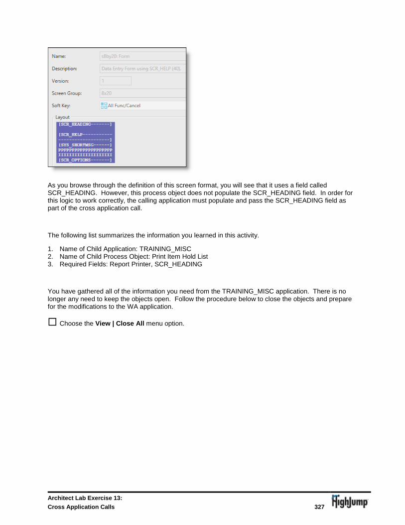
Architect Lab Exercise 13:
Cross Application Calls 327
As you browse through the definition of this screen format, you will see that it uses a field called SCR_HEADING. However, this process object does not populate the SCR_HEADING field. In order for this logic to work correctly, the calling application must populate and pass the SCR_HEADING field as part of the cross application call.
The following list summarizes the information you learned in this activity.
1. Name of Child Application: TRAINING_MISC 2. Name of Child Process Object: Print Item Hold List 3. Required Fields: Report Printer, SCR_HEADING
You have gathered all of the information you need from the TRAINING_MISC application. There is no longer any need to keep the objects open. Follow the procedure below to close the objects and prepare for the modifications to the WA application.
Choose the View | Close All menu option.
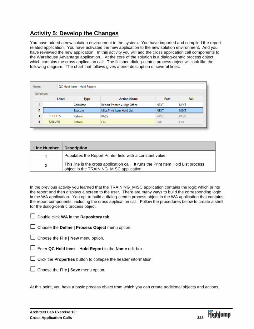
Architect Lab Exercise 13:
Cross Application Calls 328
Activity 5: Develop the Changes
You have added a new solution environment to the system. You have imported and compiled the report-related application. You have activated the new application to the new solution environment. And you have reviewed the new application. In this activity you will add the cross application call components to the Warehouse Advantage application. At the core of the solution is a dialog-centric process object which contains the cross application call. The finished dialog-centric process object will look like the following diagram. The chart that follows gives a brief description of several lines.
Line Number Description
1 Populates the Report Printer field with a constant value.
2 This line is the cross application call. It runs the Print Item Hold List process object in the TRAINING_MISC application.
In the previous activity you learned that the TRAINING_MISC application contains the logic which prints the report and then displays a screen to the user. There are many ways to build the corresponding logic in the WA application. You opt to build a dialog-centric process object in the WA application that contains the report components, including the cross application call. Follow the procedures below to create a shell for the dialog-centric process object.
Double click WA in the Repository tab.
Choose the Define | Process Object menu option.
Choose the File | New menu option.
Enter QC Hold Item – Hold Report in the Name edit box.
Click the Properties button to collapse the header information.
Choose the File | Save menu option.
At this point, you have a basic process object from which you can create additional objects and actions.

Architect Lab Exercise 13:
Cross Application Calls 329
In the previous activity you learned that the WA application must populate and pass the Report Printer field to the TRAINING_MISC application. The WA application already contains a field called Report Printer. You need to populate this field with a value before you pass it to the TRAINING_MISC application. In most printer-related solutions, the printer is read from a database table or it is provided by the end user. However, for the sake of simplicity, this exercise uses a constant value to populate the Report Printer field. Follow the procedures below to populate the Report Printer field.
Click the left-most column of line 1 (Return…PASS) to highlight the row.
Click the Insert Before button.
Choose Calculate in the Type drop-down box.
Click the Action Name edit box to bring focus to that cell.
Click the Asterisk button on the right side of the Action Name drop-down box.
Chose the Calculate Action menu option.
Enter Report Printer = Mgr Office in the Action Name edit box.
Click the Checkmark button on the right side of the Action Name drop-down box.
After you click the checkmark button, the system creates a new calculate action with the given name. Additionally, the system creates a new tab for the new calculate action along the top of the tool.
Choose the File | Save menu option
The process object should look like the graphic below.

Architect Lab Exercise 13:
Cross Application Calls 330
You have created a placeholder for the calculate action which populates the Report Printer field. Next you need to define its details. Follow the procedures below to define the content of the calculate action.
Click the Report Printer = Mgr Office tab (calculate action) along the top of the tool.
Click the Insert After button.
Choose Equals in the Operator edit box.
Choose Report Printer in the Result drop-down box.
Click the Asterisk button to the right of the Operand 1 drop-down box.
Choose Constant – String from the menu.
Type MGR_OFFICE in the Operand 1 edit box.
Choose the File | Save menu.
The finished calculate action should look like the following graphic.
You have populated the Report Printer field. In the previous activity you learned that the WA application must also populate and pass the SCR_HEADING field to the TRAINING_MISC application. The WA application already contains a field called SCR_HEADING, and the base application also populates this value. For now, there is nothing else you need to do related to this field.

Architect Lab Exercise 13:
Cross Application Calls 331
You have accounted for both of the fields required by the TRAINING_MISC application. Next you need to build the cross application call. Execute objects and execute actions operate in a parent / child paradigm. The execute object is the parent. And the execute action is the child. Some areas of the application use execute objects and execute actions to call Windows DLLs. Here, you will see that execute objects and execute actions can be used to call process objects in a second application. Essentially, execute objects and execute actions serve as the cross application call. Here the execute object points to the second application, and the execute points to the process object in that application. Follow the procedures below to create the execute object portion of the cross application call.
Choose the Define | Execute Object menu.
Choose the File | New menu.
Type Training Misc Architect Application in the Name edit box.
Choose Advantage Application in the Object Type drop-down box.
Choose TRAINING_MISC in the Application drop-down box.
Choose the File | Save menu.
The finished execute object should look like the following graphic.
You have created the execute object which points to the second application. However, this is only one component of the cross application call. You also need to account for the child process object and the two fields. Follow the procedures below to create the execute action which points to the specific process object and the handles the Report Printer and SCR_HEADING fields.
Choose the Define | Execute (Actions) menu.
Choose the File | New menu.
Type Misc.Print Item Hold List in the Name edit box.

Architect Lab Exercise 13:
Cross Application Calls 332
Choose Training Misc Architect Application in the Object Name drop-down box.
Choose Print Item Hold List in the Process Object drop-down box.
Choose the File | Save menu.
The execute action should look like the following graphic.
Earlier in the exercise, you learned that the child process object in the TRAINING_MISC application used the Report Printer Field and the SCR_HEADING field. The primary application (WA) must populate these two fields and then pass the fields to the TRAINING_MISC application during the cross application call. Follow the procedures below to pass the Report Printer field and the SCR_HEADING field to the TRAINING_MISC application.
Click the Insert After button.
Select In in the Parameter Type drop-down box.
Choose Report Printer in the Parameter drop-down box.
The execute action should look like the following graphic.
Click the Insert After button.
Select In in the Parameter Type drop-down box.
Choose SCR_HEADING in the Parameter drop-down box.

Architect Lab Exercise 13:
Cross Application Calls 333
Choose the File | Save menu option.
The execute action should look like the following graphic.
This execute action now passes the Report Printer field and the SCR_HEADING field from the WA application to the TRAINING_MISC application. However, there is one more optional field that you may want to include in the execute action. The execute action will run the Print Item Hold List process object in the TRAINING_MISC application. The Print Item Hold List process either returns with a PASS condition or a FAIL condition. It may be beneficial for the WA application to know if the Print Item Hold List process object returned PASS or FAIL. It is not possible to make this determination with the current definition of the execute action. Follow the procedures below to store the PASS / FAIL status of the Print Item Hold List process object in a base application WA field called Successful.
Click the Insert After button.
Select Return in the Parameter Type radio button.
Choose Successful in the Parameter drop-down box.
Choose the File | Save menu option.
The finished execute action should look like the following graphic.

Architect Lab Exercise 13:
Cross Application Calls 334
You have built an execute object and an execute action. Together, these components will run the Print Item Hold List process object in the TRAINING_MISC application. The WA application also makes the Report Printer field and the SCR_HEADING field available to the TRAINING_MISC application. Lastly, the execute action stores the returned PASS / FAIL status of the process object in a field called Successful. Next you need to call the execute action from a WA process object. Follow the procedures below to call the execute action from the dialog-centric process object you created earlier.
Click the QC Hold Item – Hold Report tab (process object) along the top of the tool.
Click the left-most column of line 1 (Calculate…Report Printer = Mgr Office) to highlight the row.
Click the Insert After button.
Choose Execute in the Type drop-down box.
Choose Misc.Print Item Hold List in the Action Name drop-down box.
Choose the File | Save menu option.
The finished process object should look like the following graphic. The chart that follows gives a brief description of several lines.

Architect Lab Exercise 13:
Cross Application Calls 335
Line Number Description
1 Populates the Report Printer field with a constant value.
2 This line is the cross application call. It runs the Print Item Hold List process object in the TRAINING_MISC application.
You have created a dialog-centric process object related to the report. However, in order for the system to actually print the report and display the dialog, this dialog-centric process object must be included in the business process. Follow the procedures below to review the definition of the Hold by Item business process.
Choose the Define | Business Process menu option.
Double click the Hold by Item node.
The system opens the definition of the business process object. The chart that follows gives a brief description of several lines.
Line Number Description
11 Populates the Status field with a constant of “H”
12 The transaction process object for Hold by Item. It uses the values entered by the user and places the inventory on hold in the inventory master table. It also writes an entry to the transaction log.
13 A dialog-centric process object which shows a “result” screen to the user. The “result” screen indicates how may locations were impacted by the hold.
According to the warehouse manager’s requirements, the report will show the information for the inventory that was successfully placed on the hold. The natural place to print the report is immediately after line 13. Follow the procedures below to add the report printing logic to the Hold by Item business process.
Choose the Version Control | Check Out menu option.

Architect Lab Exercise 13:
Cross Application Calls 336
Click the left-most column of line 13 (Call…QC Hold Item - Result) to highlight the row.
Click the Insert After button.
Choose Call in the Type drop-down box.
Choose QC Hold Item – Hold Report in the Action Name drop-down box.
Choose the File | Save menu option.
The finished process object should look like the following graphic. The chart that follows gives a brief description of several lines.
Line Number Description
11 Populates the Status field with a constant of “H”
12 The transaction process object for Hold by Item. It uses the values entered by the user and places the inventory on hold in the inventory master table. It also writes an entry to the transaction log.
13 A dialog-centric process object which shows a “result” screen to the user. The “result” screen indicates how may locations were impacted by the hold.
14 A dialog-centric process object which prints a report and then displays a confirmation screen to the user. This process object utilizes a cross application call.
In this exercise, you built an execute object and an execute action to run a process object in the TRAINING_MISC application which prints a report and then displays a confirmation screen to the user. You incorporated the execute action into the Hold by Item business process. You have modified all of the necessary objects to meet the requirements of the warehouse manager.
Activity 6: Compile and Activate the Changes
At this point you have modified several objects to meet the requirements dictated by the warehouse manager. However, if you run the process on the Virtual Terminal, you will see that your changes have not taken effect. In order for your changes to take effect, you must first compile the application and then activate the application. The procedures below are very generic. If you need additional details on how to

Architect Lab Exercise 13:
Cross Application Calls 337
compile and activate the application, please see the activity titled Compile and Activate the Changes in the exercise titled Exercise 1: Introduction to Advantage Architect.
Compile the application
Activate the application

Architect Lab Exercise 13:
Cross Application Calls 338
Activity 7: Test the Changes
The chart below outlines the various test cases that must be validated. Each test case defines an action you must take, and it defines the expected outcome based on the requirements. If a given test case does not yield the expected outcome, then review the steps from the previous activity. It is likely that you either missed a step or performed a step incorrectly. The test cases do not detail every keystroke. You need to use the knowledge you gained in the first activity of this exercise in order to test the scenarios.
Starting the Hold by Item Business Process
From the Main Menu choose F8, Option 7, Option 1, Option 1
Type NHFG00000 at the Item ID dialog.
Press the F2:All key at the Location dialog
Press the F8:LST key at the Reason Code dialog.
Type 1 (02 Quality Control) at the Reason Code List dialog.
Test Case Expected Outcome Pass / Fail
Press the Enter key at the Item XXXXXX Held in XX Locs Confirmation screen.
System displays a dialog asking if you are ready to print the reports.
Enter Y at the Ready to Print Reports dialog.
System displays a dialog asking you to confirm whether or not the report printed successfully.

Architect Lab Exercise 13:
Cross Application Calls 339
Press the Enter key at the Print Confirmation dialog.
System returns to the item id dialog.
Activity 8: Check in the Objects
Earlier in this exercise, you checked out several objects and made changes to them. As long as the objects are checked out in your name, you are the only developer who can alter their definitions. Because your changes met the warehouse manager’s requirements, you can make the objects available to other Architect developers in your company. In the steps below, you will check in the objects so that other developers can make additional changes to them.
Choose the View | Close All menu option.
Check in all of the objects.

Architect Lab Exercise 14:
Elevate the App Log Level 340
Architect Lab Exercise 14: Elevate the App Log Level
Introduction In this exercise you will elevate the application log level through a process object for the Physical business process.
Background Information Before a warehouse goes live with the HighJump system, a warehouse will often suspend all operations in order to perform a physical. This means that they will count all inventory in all locations in the warehouse. This inventory then becomes the master inventory for the start of the go-live event. Sometimes warehouses will also perform an annual physical after the HighJump system has been live.
The Physical Inventory business process in Warehouse Advantage is the process that is used to count the inventory during a physical. This exercise uses the Physical Inventory business process as a basis for all activities. By default, the Physical Inventory business process will not direct the user to a specific location. Instead, it relies upon the warehouse manager to devise a plan in which the counters visit all locations in the warehouse.
The concept of a log level is also central to this exercise. When the system encounters communication problems, syntax problems, and various other errors, the system writes an entry to the HighJump platform log. By default the system runs at log level 3 which instructs the HighJump system to write only specific errors and diagnostic information to the HighJump platform log. If you want to capture additional diagnostic messages to the log, then you need to raise the log level to 4 or to 5. Log level 4 and log level 5 each write increasingly more messages to the platform log.
The final concept which is central to this exercise is the concept of the application status console. At any time, you can view the entire contents of the HighJump platform log through a web-based tool called Advantage Commander. The application status consoles provide another method for viewing a subset of platform log messages. The application status console is a window on the application server that displays the platform log messages as they are being written to the log. Because the console has a buffer limit, you can only view a certain number log messages through the console.

Architect Lab Exercise 14:
Elevate the App Log Level 341
Activity 1: Understand the Current Process
This activity demonstrates the Physical Inventory business process on the RF terminal as well as its relationship to the application status console. Follow the procedures below to see how the Physical Inventory process operates in the base application.
Start the engine, if necessary.
Choose the Start | All Programs | HighJump Software | Application Status Console menu.
The system opens the application status console. However, there are no messages in the window.
Log in to the Virtual Terminal as AMY / AMY / FAAMY.
Press the F8 key to scroll to the next page.
Enter option 7 (the Inv Control menu.)
Enter option 2 (the Cycle Counts menu.)
Enter option 3 (the Physical menu.)
Enter P101 at the Location dialog.
Enter N at the Clear Location dialog.
Enter NNFG00000 at the Item ID dialog.
Enter 1 at the Pallets of 100 dialog.
Enter 2 at the Cases of 10 dialog.
Enter 3 at the Eaches dialog.
Press the Enter key at the Transaction Complete dialog.
Press the F1 key at the Location dialog to return to the main menu.
Note that the application status console remains empty. This is the norm for application log level 3.

Architect Lab Exercise 14:
Elevate the App Log Level 342
Activity 2: Understand the Requirements
This activity identifies the changes that you want to the make to the Physical Inventory business process.
The warehouse manager calls you on the phone. He requests a handful of changes to the Physical Inventory business process. As you are testing your solution in the test environment, you identify a bug in the business process that you cannot solve by reviewing the process objects in Advantage Architect. The bug occurs after you enter a quantity. You need some additional information to assist you in the troubleshooting process. Your goal is to determine and fix the root cause of the bug. Since you cannot determine the root cause by looking at the process object in Advantage Architect, you need some additional debugging information. As part of your troubleshooting process, you decide to elevate the application log level from within the Physical Inventory process object. While the elevated log level does not solve the problem, it may give you the additional information you need to identify the root cause. Notes The HighJump system provides two primary tools for debugging the business logic on a reader. The first tool is the Visual Debugger and the second tool is the application log messages. Some logic problems may be easier to identify with the Visual Debugger, and others may be easier to identify with additional application log messages. The purpose of this exercise is not to endorse one practice over another. Rather, it demonstrates one of several options for debugging the business logic.
Activity 3: Develop the Changes
In order to gather the additional debugging information, you must create two new send actions and then insert the send actions into the Physical process object. The finished process object will look like the following graphic. The chart that follows gives a brief description of several lines.

Architect Lab Exercise 14:
Elevate the App Log Level 343
Line Number Description
23 Elevate the log level to 5.
24 A dialog-centric process object which prompts for a Quantity and handles the validation of the user-entered value.
27 – 29 Serial Number processing.
30 The transaction process object. This process object updates the tables based upon the user-entered values and writes an entry to the transaction log table.
31 Restore the log level back to 3
32 Displays the transaction complete dialog.
A send action sends a message to a specified device. In this case, the device is the HighJump program (called a manager) which handles the platform log levels. One send action raises the log level to 5. The other one returns the log level back to 3. Follow the procedures below to create the send action which raises the log level to 5.
In Advantage Architect, click the Repository tab near the lower left corner of the window.
Double click the WA application in the Repository tab.
Choose the Define | Send (Actions) menu option.
Choose the File | New menu option.
Enter Set App Log 5 in the Name edit box.
Click the asterisk button to the right of the Destination Device drop-down box.
Choose the Constant – String menu option.
Enter SYS_SET_APP_LOG_LEVEL in the Destination Device edit box.
Click the asterisk button to the right of the Output Field drop-down box.

Architect Lab Exercise 14:
Elevate the App Log Level 344
Choose the Constant – String menu option.
Type 5 in the Output Field edit box.
Choose the File | Save menu option.
The finished send action should look like the following graphic.
The send action which returns the log level to 3 is similar to the one you created. Rather than creating a new one from scratch, you will copy the send action from above and then modify it accordingly. Follow the procedures below to create a send action which sets the log level to 3.
Choose the File | Copy As menu option.
The system displays the Copy As window.
Enter Set App Log 3 in the New Object Name edit box.
Click the OK button.
Enter 3 in the Output Field edit box.
Choose the File | Save menu option.
The finished send action should look like the following graphic.

Architect Lab Exercise 14:
Elevate the App Log Level 345
You have created two send actions which raise and restore the log level. However, in order for the system to raise the log level, you must include these send actions in the Physical business process. The procedures below show a simplistic method for including the send actions in the Physical business process. The system will elevate the log level to 5 unconditionally. While this unconditional method is effective in a testing environment, it is not the best method for a production environment. If you needed to promote this application to a production environment, you would probably want the ability to turn off the elevated log level without requiring a new application. The best way to include the conditional logic would be to add a control parameter to the t_whse_control table as you did in the exercise titled Exercise 4: Calculate Actions.
Follow the procedures below to review the definition of the Physical business process object.
Choose the Define | Business Process menu option.
Double click the Physical node.
The system opens the definition of the business process object. The chart that follows gives a brief description of several lines.
Line Number Description
23 A dialog-centric process object which prompts for a Quantity and handles the validation of the user-entered value.
26 – 28 Serial number processesing

Architect Lab Exercise 14:
Elevate the App Log Level 346
29 The transaction process object. This process object updates the tables based upon the user-entered values and writes an entry to the transaction log table.
30 Displays the transaction complete dialog.
Using the naming conventions you learned in the exercise titled Exercise 7: Add a New Business Process, you can identify line 23 as the dialog-centric process object which prompts for a quantity. Since you suspect that the logic problem is around the quantity prompt, the natural place to elevate the log level is shortly before the dialog centric process object. Follow the procedures below to elevate the log level in the Physical process.
Choose the Version Control | Check Out menu option.
Click the left-most column of Line 23 (Call…Physical - Quantity) to highlight the line.
Click the Insert Before button.
Choose Send in the Type drop-down box.
Choose Set App Log Level 5 in the Action Name drop-down box.
Choose the File | Save menu option.
The process object should look like the following graphic.
You have modified the business process to elevate the log level to 5 just before the user enters a quantity. If you don’t make any additional changes to the business process, the system will remain in the elevated log level until an administrator manually changes it. To avoid this situation, you need to revert the log level back to 3. Since you suspect the logic problem is around the quantity prompt, which is the final prompt in the sequence, the natural place to revert the log level is after the system has updated the tables and inserted the record into the log. Follow the procedures below to revert the log level to 3 in the Physical business process.
Click the left-most column of Line 30 (Call…Physical - TX) to highlight the line.
Click the Insert After button.
Choose Send in the Type drop-down box.
Choose Set App Log Level 3 in the Action Name drop-down box.
Choose the File | Save menu option.

Architect Lab Exercise 14:
Elevate the App Log Level 347
The finished process object should look like the following graphic. The chart that follows gives a brief description of several lines.
Line Number Description
23 Elevate the log level to 5.
24 A dialog-centric process object which prompts for a Quantity and handles the validation of the user-entered value.
27 – 29 Serial Number processing
30 The transaction process object. This process object updates the tables based upon the user-entered values and writes an entry to the transaction log table.
31 Restore the log level back to 3
32 Displays the transaction complete dialog.
You have modified the Physical process so that it elevates the log level to 5 after the user enters a quantity. And you have modified the process to that it reverts the log level back to 3 after it inserts a record into the transaction log table. You have modified all of the necessary objects to gather the additional debugging information.
Activity 4: Compile and Activate the Changes
At this point you have modified several objects to meet the requirements. However, if you run the process on the Virtual Terminal, you will see that your changes have not taken effect. In order for your changes to take effect, you must first compile the application and then activate the application. The procedures below are very generic. If you need additional details on how to compile and activate the application, please see the activity titled Compile and Activate the Changes in the exercise titled Exercise 1: Introduction to Advantage Architect.
Compile the application

Architect Lab Exercise 14:
Elevate the App Log Level 348
Activate the application

Architect Lab Exercise 14:
Elevate the App Log Level 349
Activity 5: Test the Changes
The chart below outlines the various test cases that must be validated. Each test case defines an action you must take, and it defines the expected outcome based on the requirements. If a given test case does not yield the expected outcome, then review the steps from the previous activity. It is likely that you either missed a step or performed a step incorrectly. The test cases do not detail every keystroke. You need to use the knowledge you gained in the first activity of this exercise in order to test the scenarios.
Starting the Physical Business Process
From the Main Menu choose F8, Option 7, Option 2, Option 3
Enter P101 at the Location dialog.
Test Case Expected Outcome Pass / Fail
Enter N at the Clear Location dialog.
No activity in the application status console.
Enter NNFG00000 at the Item ID dialog.
System displays some new information in the application status console.
Enter 1, 2, and 3 at the Pallets, Cases, and Eaches dialogs respectively.
System displays a significant amount of information in the application status console.

Architect Lab Exercise 14:
Elevate the App Log Level 350
Press the Enter key at the Transaction Complete dialog.
No additional activity in the application status console.
Enter P102 at the Location dialog.
No additional activity in the application status console.

Architect Lab Exercise 14:
Elevate the App Log Level 351
Activity 6: Check in the Objects
Earlier in this exercise, you checked out several objects and made changes to them. As long as the objects are checked out in your name, you are the only developer who can alter their definitions. Because your changes met the warehouse manager’s requirements, you can make the objects available to other Architect developers in your company. In the steps below, you will check in the objects so that other developers can make additional changes to them.
Choose the View | Close All menu option.
Check in all of the objects.
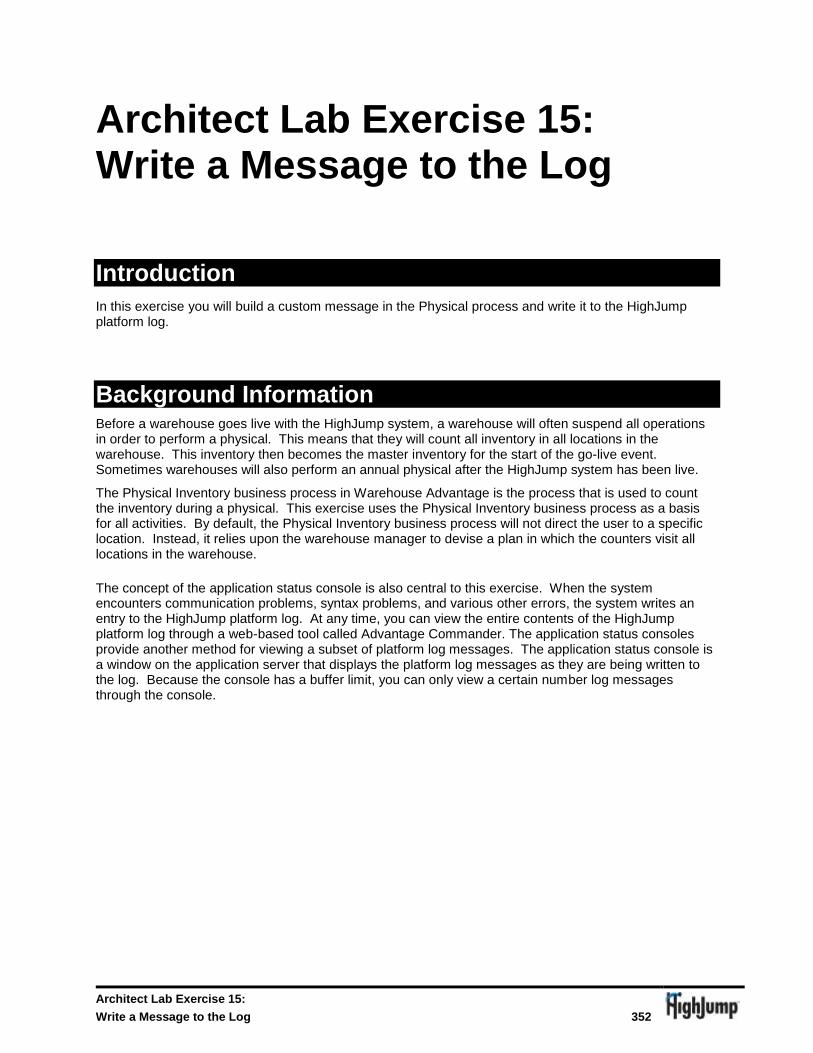
Architect Lab Exercise 15:
Write a Message to the Log 352
Architect Lab Exercise 15: Write a Message to the Log
Introduction
In this exercise you will build a custom message in the Physical process and write it to the HighJump platform log.
Background Information Before a warehouse goes live with the HighJump system, a warehouse will often suspend all operations in order to perform a physical. This means that they will count all inventory in all locations in the warehouse. This inventory then becomes the master inventory for the start of the go-live event. Sometimes warehouses will also perform an annual physical after the HighJump system has been live.
The Physical Inventory business process in Warehouse Advantage is the process that is used to count the inventory during a physical. This exercise uses the Physical Inventory business process as a basis for all activities. By default, the Physical Inventory business process will not direct the user to a specific location. Instead, it relies upon the warehouse manager to devise a plan in which the counters visit all locations in the warehouse.
The concept of the application status console is also central to this exercise. When the system encounters communication problems, syntax problems, and various other errors, the system writes an entry to the HighJump platform log. At any time, you can view the entire contents of the HighJump platform log through a web-based tool called Advantage Commander. The application status consoles provide another method for viewing a subset of platform log messages. The application status console is a window on the application server that displays the platform log messages as they are being written to the log. Because the console has a buffer limit, you can only view a certain number log messages through the console.

Architect Lab Exercise 15:
Write a Message to the Log 353
Activity 1: Understand the Current Process
This activity demonstrates the Physical Inventory business process on the RF terminal. Follow the procedures below to see how the Physical Inventory process operates in the base application.
Choose the Start | All Programs | HighJump Software | Application Status Console menu option.
The system opens the application status console. There are no messages in the console.
Log in to the Virtual Terminal as AMY / AMY / FAAMY.
Press the F8 key to scroll to the next page.
Enter option 7 (the Inv Control menu.)
Enter option 2 (the Cycle Counts menu.)
Enter option 3 (the Physical menu.)
Enter P101 at the Location dialog.
Enter Y at the Clear Location dialog.
There is still no activity in the application status console.
Press the F1 key at the Item ID dialog
Press the F1 key at the Location dialog to return to the main menu.

Architect Lab Exercise 15:
Write a Message to the Log 354
Activity 2: Understand the Requirements
This activity identifies the changes that you want to the make to the Physical Inventory business process.
The warehouse manager calls you on the phone. He requests a handful of changes to the Physical Inventory business process. As you are testing your solution in the test environment, you introduce a bug into the business process that you cannot identify simply by reviewing the process objects in Advantage Architect. You need some additional information to assist you in the troubleshooting process. The bug is inconsistent in nature. Sometimes the bug is present, and sometimes the process works according to the design. After some additional troubleshooting, you begin to have suspicions that the bug only appears when the user chooses the Y option at the Clear Location dialog. However, you have not been able to prove or disprove your hypothesis. Your goal is to determine and fix the root cause of the bug. And since you cannot determine the root cause by looking at the process object in Advantage Architect, you need some additional information. As part of your troubleshooting process, you decide to write a custom message to the HighJump platform log every time the user enters Y at the Clear Location screen. The following is the text message you decide to write to the log:
User [xxxx] chose to clear location [xxxxxx] in the Physical Inventory process. While this log message does not solve the problem, it may confirm your suspicions. Notes The HighJump system provides two primary tools for debugging the business logic on a reader. The first tool is the Visual Debugger and the second tool is the application log messages. Some logic problems may be easier to identify with the Visual Debugger, and others may be easier to identify with additional application log messages. The purpose of this exercise is not to endorse one practice over another. Rather, it demonstrates one of several options for debugging the business logic.
Activity 3: Develop the Changes
In order to gather the additional debugging information, you must build a custom message and then write it to the HighJump platform log. The base application contains a dialog-centric process object which displays a Clear Location screen in the Physical process. You will modify this process object so that it handles the logging information. The finished process object will look like the following graphic. The chart that follows gives a brief description of several lines.
Line Number Description

Architect Lab Exercise 15:
Write a Message to the Log 355
8 Verifies that the user entered a Y or N at the (Clear Location) screen.
9 Asks the question, “Did the user enter a Y at the screen?”
10 Populates the Log Msg field with a custom log message.
11 Writes the Log Msg field to the HighJump platform log.
Earlier in this exercise you saw that the RF terminal displayed a Clear Location prompt. In order to add the debugging logic, you must find this prompt in the Physical business process object. Follow the procedures below to identify the Clear Location prompt in the Physical business process.
In Advantage Architect, double click WA in the Repository tab.
Choose the Define | Business Process menu option.
Double click the Physical node.
The system opens the definition of the business process object. The chart that follows gives a brief description of several lines.
Line Number Description
1 Sets the transaction code for the Physical business process
4 A dialog-centric process object which prompts for a Location and handles the validation of the user-entered value.
6 A dialog-centric process object which prompts for a Clear Location and handles the validation of the user-entered value.

Architect Lab Exercise 15:
Write a Message to the Log 356
9 A dialog-centric process object which prompts for an LP and handles the validation of the user-entered value.
Line 5 does not contain a label. However if you apply the naming conventions you learned in the exercise titled Exercise 7: Add a New Business Process, you can identify line 5 as the dialog-centric process object which displays the Clear Location screen. Follow the procedures below review the Clear Location dialog-centric process object.
Click the Action Name column of line 6 (Call…Physical – Clear Location) to bring focus.
Double click the Action Name column of line 6 (Call… Physical – Clear Location).
The system opens the definition of the process object. The chart that follows gives a brief description of several lines.
Line Number Description
3 Populates the SCR fields with pick-area-related resources which the system will display on the screen. Initializes the SCR_OPTIONS field to an empty value. For additional details on this calculate action, please see the exercise titled Exercise 5: Display Text on the Reader.
4 Calls the Dialog process object. Because of the values set in line 3, this process object prompts for a Clear Location value and then waits for the user to respond. For additional details on the Dialog process object, please see the exercise titled Exercise 5: Display Text on the Reader.
5 Asks the question, “Did the user press the F1 function key?” (on the standard pick area prompt screen.)
6 Asks the question, “Did the user enter an empty value on the screen?”
7 Populates the Response field with the value entered by the user.
8 Verifies that the user entered a Y or N at the screen.

Architect Lab Exercise 15:
Write a Message to the Log 357
9 Asks the question, “Did the user enter a Y at the screen?”
You want to add the message to the log only when the user enters Y at the Clear Location screen. From line 9, the system continues with the next line (line 10) if the user entered a Y. And it branches somewhere else if the user entered a N. The natural place to add the new logic is immediately after line 9, when the system has determined that the user entered a Y. Follow the procedures below to add a calculate action which builds a custom message.
Choose the Version Control | Check Out menu option.
Click the left-most column of line 9 (Compare…Response = “Y”?) to highlight the row.
Click the Insert After button.
Choose Calculate in the Type drop-down box.
Click the Asterisk button on the right side of the Action Name drop-down box.
Chose the Calculate Action menu option.
Enter Log: Clear Loc in Physical in the Action Name edit box.
Click the Checkmark button on the right side of the Action Name drop-down box.
After you click the checkmark button, the system creates a new calculate action with the given name. Additionally, the system creates a new tab for the new calculate action along the top of the tool.
Choose the File | Save menu option.
The process object should look like the following graphic.
You have created the placeholder for the calculate action which builds the log message. Next you need to define its details. According to the requirements, you need to construct a log message that reads, “User [xxxx] chose to clear location [xxxxxx] in the Physical Inventory process”. In Advantage Architect, there are two primary ways to build this message. Either you can use a series of concatenate operators in a calculate action. Or you can use a resource. The resource option is a faster development cycle. However, the base application does not translate the log messages into multiple languages.

Architect Lab Exercise 15:
Write a Message to the Log 358
Consequently, all of the log messages in the base application are built with a series of concatenate operators. Either method would work in this example. In order to conform to the other log messages in the base application, this exercise uses the concatenation method. Follow the procedures below to build the custom log message with multiple concatenations.
Click the Log: Clear Loc in Physical tab (calculate action) along the top of the tool.
Click the Insert After button.
Click Equals in the Operator multi line edit box.
Choose Log Msg in the Result drop-down box.
To the right, click the Operand 1 cell to bring focus.
Click the asterisk button of the Operand 1 cell.
Choose the Constant – String menu.
Type User [ in the Operand 1 edit box.
Choose the File | Save menu option.
The calculate action should look like the following graphic.
Click the Insert After button.
Click Concatenate in the Operator multi line edit box.
Choose Log Msg in the Result drop-down box.
Choose Log Msg in the Operand 1 drop-down box.
Choose User ID in the Operand 2 drop-down box.
Choose the File | Save menu option.
The calculate action should look like the following graphic.

Architect Lab Exercise 15:
Write a Message to the Log 359
Click the Insert After button.
Click Concatenate in the Operator multi line edit box.
Choose Log Msg in the Result drop-down box.
Choose Log Msg in the Operand 1 drop-down box.
Click the asterisk button to the right of the Operand 2 drop-down box.
Choose the Constant – String menu option.
Type ] chose to clear location [ in the Operand 2 edit box.
Choose the File | Save menu option.
The calculate action should look like the following graphic.
Click the Insert After button.
Click Concatenate in the Operator multi line edit box.
Choose Log Msg in the Result drop-down box.
Choose Log Msg in the Operand 1 drop-down box.
Choose Location in the Operand 2 drop-down box.
Choose the File | Save menu option.
The calculate action should look like the following graphic.

Architect Lab Exercise 15:
Write a Message to the Log 360
Click the Insert After button.
Click Concatenate in the Operator multi line edit box.
Choose Log Msg in the Result drop-down box.
Choose Log Msg in the Operand 1 drop-down box.
Click the asterisk button to the right of the Operand 2 drop-down box.
Choose the Constant – String menu option.
Type ] in the Physical Inventory process. in the Operand 2 edit box.
Choose the File | Save menu option.
The finished calculate action should look like the following graphic.
You have created a calculate action which builds a custom log message. And you have included the calculate action in the Physical business process. However, the system will still not write the message to the platform log. You must explicitly instruct the system to write a message to the log. This is done through a send action.
A send action simply takes a field and writes it to a device. A device can be a text file. It can be a host system like Peoplesoft. In this case, the device is the HighJump platform log. The base application contains a send action which writes the Log Msg field to the platform log. Consequently, you will utilize a base send action instead of creating your own. Follow the procedures below to write the custom Log Msg field to the HighJump platform log.
Click the Physical – Clear Location tab (process object) along the top of the tool.
Architect Lab Exercise 15:
Write a Message to the Log 361
Click the left-most column of line 10 (Calculate…Log: Clear Loc in Physical) to highlight the row.
Click the Insert After button.
Choose Send in the Type drop-down box.
Choose Log Msg to APPLOG3 (Info) in the Action Name drop-down box.
Choose the File | Save menu option.
The finished process object should look like the following graphic. The chart that follows gives a brief description of several lines.
Line Number Description
8 Verifies that the user entered a Y or N at the screen.
9 Asks the question, “Did the user enter a Y at the screen?”
10 Populates the Log Msg field with a custom log message.
11 Writes the Log Msg field to the HighJump platform log.
You have created a calculate action which builds a custom log message. And you have directed the system to write the custom message to the HighJump platform log. You have modified all of the necessary objects to capture the additional debugging information.
Activity 4: Compile and Activate the Changes
At this point you have modified several objects to meet the requirements dictated by the warehouse manager. However, if you run the process on the Virtual Terminal, you will see that your changes have not taken effect. In order for your changes to take effect, you must first compile the application and then activate the application. The procedures below are very generic. If you need additional details on how to compile and activate the application, please see the activity titled Compile and Activate the Changes in the exercise titled Exercise 1: Introduction to Advantage Architect.
Compile the application

Architect Lab Exercise 15:
Write a Message to the Log 362
Activate the application

Architect Lab Exercise 15:
Write a Message to the Log 363
Activity 5: Test the Changes
The chart below outlines the various test cases that must be validated. Each test case defines an action you must take, and it defines the expected outcome based on the requirements. If a given test case does not yield the expected outcome, then review the steps from the previous activity. It is likely that you either missed a step or performed a step incorrectly. The test cases do not detail every keystroke. You need to use the knowledge you gained in the first activity of this exercise in order to test the scenarios.
Starting the Physical Business Process
From the Main Menu choose F8, Option 7, Option 2, Option 3
Test Case Expected Outcome Pass / Fail
Enter P101 at the Location dialog. Then enter Y at the Clear Location dialog.
System displays the custom message in the application status console.
Enter P102 at the Location dialog. Then enter N at the Clear Location dialog.
No additional activity in the application status console.
Activity 6: Check in the Objects
Earlier in this exercise, you checked out several objects and made changes to them. As long as the objects are checked out in your name, you are the only developer who can alter their definitions. Because your changes met the warehouse manager’s requirements, you can make the objects available to other Architect developers in your company. In the steps below, you will check in the objects so that other developers can make additional changes to them.
Choose the View | Close All menu option.
Check in all of the objects.

Architect Lab Exercise 16:
Initiate a Background Process 364
Architect Lab Exercise 16: Initiate a Background Process
Introduction
In this exercise you will run a process object in the background that does not display any screens to an RF user.
Background Information All of the solutions you have developed so far have had a user interface. And you have tested all of your changes through a Virtual Terminal. However, there may be times when you want to design a process object that starts when the engine starts and then continuously runs in the background without any user interface. This exercise utilizes one of the background process objects.
Also central to this exercise is the concept of a divert. As packages travel along a conveyor system, they eventually will be pushed down a path towards a shipping door. A divert is the act of pushing a package off the main conveyor loop and down a shipping lane towards a shipping door.
After a package has been picked, it is placed on the conveyor, and Warehouse Advantage sends a set of divert instructions to the conveyor system indicating the destination shipping lane for each package. While there are many potential solutions, usually, this is done in two phases. In phase 1, the picking process writes the divert instructions to a database table. This information is called a divert request. In phase 2, a background process continuously polls for data in the staging table. When it finds a request, it formats the data, and then sends a message to the conveyor system. This exercise works with a solution that follows this two-phase model.

Architect Lab Exercise 16:
Initiate a Background Process 365
Activity 1: Understand the Current Process
This activity demonstrates how the system operates without the divert background process. Follow the procedures below to see how the application status console behaves in the base application.
Choose the Start | All Programs | HighJump Software | Application Status Console menu option.
The system opens the application status console. There are no messages in the console.
Start the engine, if necessary.
After the initial set of messages, the application status console remains quiet. This is the norm.
Activity 2: Understand the Requirements
This activity identifies the changes that you need to make to the base system.
You are working with a team of HighJump developers on a 2-phase solution to process divert requests. The HighJump team has completed much of the work on the servers at their headquarters. They deliver the new application (with the completed process objects) and a SQL script to you so that you can prepare your test environment for testing against the conveyor. One of the process objects they deliver to you is designed to start when the engine starts, and then run as a background process.
The HighJump team asks you to configure your test environment as follows:
1. Import, compile, and activate the new application
2. Run the SQL script to create the necessary tables.

Architect Lab Exercise 16:
Initiate a Background Process 366
3. Configure the process object to run as a background process.
Activity 3: Import, Compile, and Activate the Divert Application
The HighJump developer team gave you an Advantage Architect application which reads the divert requests from a database table and then passes the divert information to the conveyor. Before you can do anything else, you must import, compile, and activate the application.
The divert application in this exercise is the same one you used in the exercise titled Exercise 14: Cross Application Calls. If you have not performed that exercise, you will need to refer to Exercise 14 in order to complete some of the steps below. Follow the procedures below, to import, compile, and activate the divert application delivered by the HighJump developer team.
Create the TRAININGMISC solution environment, if necessary. (for additional details, please see the exercise titled Exercise 13: Cross Application Calls)
Import the TRAINING_MISC application, if necessary. (for additional details, please see the exercise titled Exercise 13: Cross Application Calls)
Compile and activate the TRAINING_MISC application, if necessary. (for additional details, please see the exercise titled Exercise 13: Cross Application Calls)
Activity 4: Review the Divert Application
In this activity you will review the existing divert logic in the application developed by the HighJump team.
The HighJump developer team gave you an Advantage Architect application which reads the divert requests from a database table and then passes the divert information to the conveyor. The only pieces of information you need to setup a background process is the application name and the process object name. However, for the sole purpose of practice, you will review the logic in the process object before you make any additional changes to the system. Follow the procedures below to review the logic in the process object delivered by the HighJump team.
Click the Repository tab in Advantage Architect.
Double-click the TRAINING_MISC node.
Choose the Define | Process Object menu.
Double click the Process Divert Queue node.
The system opens the definition of the process object. The chart that follows gives a brief description of several lines.

Architect Lab Exercise 16:
Initiate a Background Process 367
Line Number Description
2 Establishes a connection with the AAD database
5 – 6 Unconditionally writes a message to the application status console indicating that it is looking for a record in the divert queue.
7 – 8 Attempts to find an unprocessed record in the divert queue table. Asks the question, “Did the system find any data?” If an unprocessed row was found, the system continues with line 11. Otherwise, it continues with line 16.
11 – 12 Copies the data from the database table into a second set of fields.
13 Sends a message to the application status console; formats the data; sends the data to the conveyor system; marks the data in the table as processed. Then it returns to the top of the loop.
16 Sleeps for 20 seconds. Then it returns to the top of the loop.
Barring a database error, this process object will run continuously until the TRAININGMISC solution environment stops. It writes a message to the HighJump platform log, which the system will also display on the application status console. Then it sends any unprocessed divert requests to the conveyor and then waits 20 seconds. After that, it returns to the top of the loop.

Architect Lab Exercise 16:
Initiate a Background Process 368
Click the Properties button to the right of the Name edit box.
The system displays the master properties for the process object. Note that the Sub Type property is set to Triggered. All process objects that run in the background must have the Sub Type property set to Triggered.
Activity 5: Build the Divert Table in the Database
In addition to the new application, the HighJump team also delivered a SQL script to you. The SQL script builds the table in the database which houses all of the divert requests. Follow the procedures below to create the divert table in the database.
Open the SQL Server Management Studio tool and log into it.
Choose the File | Open | File menu option.
Click the Desktop button on the left side of the window.
Navigate to the Training \ Releases \ Release 10 … folder.
Click the t_divert_queue_release_10.sql file in order to highlight it.
Click the Open button.
The system opens the SQL script.
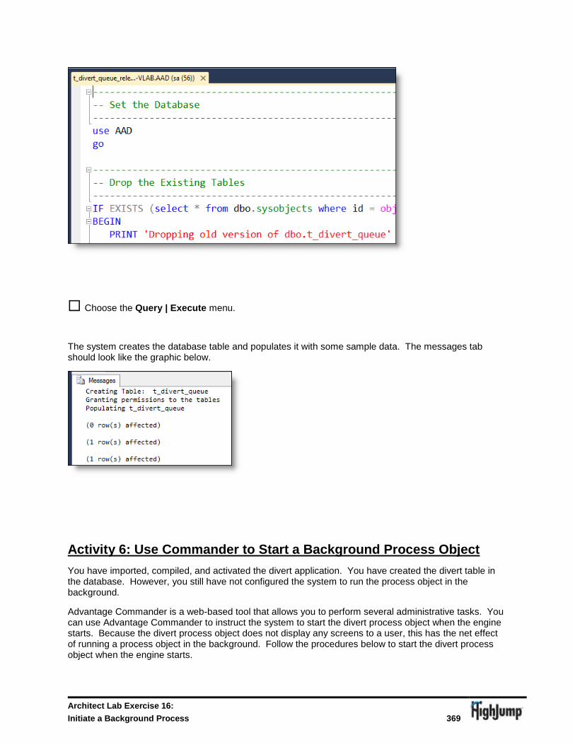
Architect Lab Exercise 16:
Initiate a Background Process 369
Choose the Query | Execute menu.
The system creates the database table and populates it with some sample data. The messages tab should look like the graphic below.
Activity 6: Use Commander to Start a Background Process Object
You have imported, compiled, and activated the divert application. You have created the divert table in the database. However, you still have not configured the system to run the process object in the background.
Advantage Commander is a web-based tool that allows you to perform several administrative tasks. You can use Advantage Commander to instruct the system to start the divert process object when the engine starts. Because the divert process object does not display any screens to a user, this has the net effect of running a process object in the background. Follow the procedures below to start the divert process object when the engine starts.

Architect Lab Exercise 16:
Initiate a Background Process 370
If you want the engine to start a process object in the background when the engine starts, you must associate the process object with a “phantom file.” The “phantom file” does not exist on the hard-drive. However, it will serve the desired purpose of initiating the process object when the engine starts.
Open the HighJump One Platform UI, if necessary.
HighJump One Platform UI Logon
Open Internet Explorer.
Enter http://[server name]:30000/core/Default.html in the address bar.
(where “[server name]” represents the machine name of the web server.)
Use the HighJump One Platform UI #1 section of the login.txt file in the folder on the desktop to populate the User Name edit box and the Password edit box.
Click the Login button.
Click the Menu | Advantage Commander | Advantage Commander | File Devices | Files menu.
The system does not display a list of previously-defined files. Rather, it asks for an application server and a solution environment. Just like a physical terminal, a file definition only “communicates” with one solution environment on one server. You must specify these two pieces of information before you move forward with the file definition. Since the background process object is a component of the TRAININGMISC solution environment, you will choose that option instead of WA.
Click the Select a Solution Environment on Server [xxxxx] link.
The system displays the Select Solution Environment report page.

Architect Lab Exercise 16:
Initiate a Background Process 371
Click the Work with Solution Environment [TRAININGMISC] link.
The system displays a list of all previously defined file definitions. In this case, there are none. The screen should look like the following graphic.
Click the New Device button in the Action Bar.
The system prompts for the file type of the new device.
Choose FILE TRIGGERED in the File Type drop-down box.

Architect Lab Exercise 16:
Initiate a Background Process 372
Click the Add button.
The system opens a blank template for a file definition. The screen should look like the following graphic.
Enter TRIG: Process Divert Queue in the Name edit box.
Enter DIVERT in the ID edit box.
Choose Active the Status drop-down box.
Choose Process Divert Queue in the Process Object drop-down box.
This is the process object that you reviewed earlier in this exercise.
Choose AutoStart in the Startup drop-down box.
The Auto Start option indicates that the system will start the above process object when the engine starts.

Architect Lab Exercise 16:
Initiate a Background Process 373
Click the Insert button.
The system creates the file definition. It indicates that the change will take effect the next time you start the solution environment.
Click the OK button.
The system lists the new file definition.
You have imported, compiled, and activated the divert application. You have created the divert table in the database. And you have configured Advantage Commander so that the system starts the divert process object when the engine starts. You have modified all of the necessary objects to run the divert process object in the background.

Architect Lab Exercise 16:
Initiate a Background Process 374
Activity 7: Test the Changes
The chart below outlines the various test cases that must be validated. Each test case defines an action you must take, and it defines the expected outcome based on the requirements. If a given test case does not yield the expected outcome, then review the steps from the previous activity. It is likely that you either missed a step or performed a step incorrectly. The test cases do not detail every keystroke. You need to use the knowledge you gained in the first activity of this exercise in order to test the scenarios.
Test Case Expected Outcome Pass / Fail
Stop the TRAININGMISC solution environment in the AWESM tool, and then restart it.
After the initial set of standard startup messages in the Application Status console, the system displays a set of “Checking for divert requests…” and “Diverting record for…” messages. After 7 sets of these messages, the system displays the “Checking for divert requests….” message every 20 seconds.
If you are familiar with SQL Server, then update the status column of all rows in the t_divert_queue table to NEW. If you are not familiar with SQL Server, then skip this test case.
The system displays another 7 sets of the divert-specific messages.

Architect Lab Exercise 17:
Auto Launch Visual Debugger 375
Architect Lab Exercise 17: Auto Launch Visual Debugger
Introduction In this exercise you will launch the Visual Debugger tool from within the definition of a process object.
Background Information This exercise uses a background process object called Crash Recovery as a basis for all activities. When the Warehouse Advantage solution environment starts, it initiates a background process object called Crash Recovery. The purpose of Crash Recovery is to perform some minimal data cleanup in the event that the engine was shut down unexpectedly. Because this process object runs in the background, there is no user interface.
Also central to this exercise is the concept of the Visual Debugger tool. Visual Debugger is a tool which allows you to debug a process object line by line. This topic was addressed in the online prework material. For additional information on the Visual Debugger tool, please review the online videos on HighJump University or the associated help file on the Documentation Site.
The third component central to this exercise is the Windows service called Advantage Workflow Engine Service. Windows services are programs that run in the background. When you start and stop the HighJump engine through the Advantage Workflow Engine Service Manager (also called the AWESM tool), the system is actually controlling the Windows service mentioned above.

Architect Lab Exercise 17:
Auto Launch Visual Debugger 376
Activity 1: Understand the Current Process
This activity demonstrates the Crash Recovery process through the application status console. Follow the procedures below to see how the Crash Recovery process operates in the base application.
Shut down the engine, if necessary.
Choose the Start | All Programs | HighJump Software | Application Status Console menu.
The system opens the application status console. However, there are no messages in the window.
Start the engine.
The system displays several messages in the application status console window. These messages are generated by the background process called Crash Recovery.
Activity 2: Understand the Requirements
This activity identifies the changes that you want to make to the Crash Recovery process.
You recently made some changes to the Crash Recovery process. A couple days after you promote the changes into production, the warehouse manager calls you on the phone. He indicates that after the engines starts, there are always a couple material handlers who cannot log into the terminals because they are already associated with a different terminal. He asks you to solve the problem.

Architect Lab Exercise 17:
Auto Launch Visual Debugger 377
You suspect that you might have introduced the problem with the recent changes to the Crash Recovery process. You review the process object, but you cannot find the root cause. You decide the best course of action is to troubleshoot the logic on the development server with the Visual Debugger. However, because there is no user interface to the Crash Recovery process, you cannot easily start the debugger. Instead, you choose to modify the Crash Recovery process object so that it launches the debugger automatically.
Notes The HighJump system provides two primary tools for debugging a process object. The first tool is the Visual Debugger and the second tool is the application log messages. Some logic problems may be easier to identify with the Visual Debugger, and others may be easier to identify with additional application log messages. The purpose of this exercise is not to endorse one practice over another. Rather, it demonstrates one of several options for debugging the business logic.
Activity 3: Develop the Changes
In order to launch the debugger automatically during the Crash Recovery process, you must add a single line to the process object. The graphic below shows the finished process object. The chart that follows gives a brief description of several lines.
Line Number Description
1 Launch the Visual Debugger
2 Populate the Log Msg field with a message.
3 Write the Log Msg field to the HighJump platform log.
Follow the procedures below to review the current contents of the Crash Recovery business process.
In Advantage Architect, double click WA in the Repository tab.
Choose the Define | Process Object menu option.
Double click the Crash Recovery node.

Architect Lab Exercise 17:
Auto Launch Visual Debugger 378
The system opens the definition of the process object. The chart that follows gives a brief description of several lines.
Line Number Description
1 Populate the Log Msg field with a message.
2 Write the Log Msg field to the HighJump platform log.
3 Establish a connection with the AAD database
4 Populate the Log Msg field with a message.
5 Write the Log Msg field to the HighJump platform log.
6 Send a query to the database server which updates the location master table.
In order to launch the debugger automatically, you must use a send action to send the text “DEBUGBREAK” to a device called “SYS_DEVICE”. The base application contains a send action which does this. Consequently, you will utilize a base send action instead of creating your own. Since you are not sure where the error occurs, you want to launch the Visual Debugger near the top of the process object. The natural place to add the logic is at line 1. Follow the procedures below to launch the Visual Debugger at the top of Crash Recovery process object.
Choose the Version Control | Check Out menu.
Click the left-most column of line 1 (calculate: Log: Initializing System) in order to highlight the line.
Click the Insert Before button.
Choose Send in the Type drop-down box.
Choose Start Debugger in the Action Name drop-down box.
Choose the File | Save menu option.

Architect Lab Exercise 17:
Auto Launch Visual Debugger 379
The finished process object should look like the following graphic. The chart that follows gives a brief description of several lines.
Line Number Description
1 Launch the Visual Debugger
2 Populate the Log Msg field with a message.
3 Write the Log Msg field to the HighJump platform log.
When the Advantage Engine starts it runs a Windows service in the background. Most customers configure this service to log into the operating system with a network account. This allows the HighJump system to interact with network folders and network printers. However, in order for the system to launch the Visual Debugger through a process object, the background service must log in with the same account the developer used to log in to the operating system. And the service must be configured to interact with the desktop. Both of these limitations make it unreasonable to launch the Visual Debugger through a process object in a production system. The following changes should only be done in a testing environment. Follow the procedures below to modify the Windows service which controls the HighJump engine.
Choose the Start | Administrative Tools | Services menu option.
The system opens a dialog showing all of the operating system services.
Double click the Advantage Workflow Engine Service entry.

Architect Lab Exercise 17:
Auto Launch Visual Debugger 380
The system opens the parameters associated with the specific service.
Click the Log On tab.
Click the Local System Account radio button.
Check the Allow Service to Interact with Desktop checkbox.
The service parameters should look like the following graphic.
Click the OK button.
The training machines are running Windows Server 2012 R2. Because of this, there is one additional setting that must be modified in order to auto launch Visual Debugger. You must modify a setting inside of the Windows Registry.
Warning! The Windows Registry contains many low-level settings which drive the operating system. If you modify the registry incorrect, you run the risk of severely damaging your system. Proceed with extreme caution when performing this procedure outside of a training environment.
Choose the Start | All Programs menu.
In addition to displaying a list of the applications, the system also displays a search feature near the upper right corner.

Architect Lab Exercise 17:
Auto Launch Visual Debugger 381
Enter REGEDIT in the search edit box.
On the left side of the screen, the system displays an application that matches your search criteria.
Click the REGEDIT application icon.
The system opens the Registry Editor.
Expand the following keys
HKEY_LOCAL_MACHINE | SYSTEM | CurrentControlSet | Control | Windows
The system displays several different settings.

Architect Lab Exercise 17:
Auto Launch Visual Debugger 382
Double click the NoInteractiveServices key.
The system displays the key name and its current value.
Enter 0 in the Value Data edit box.
Click the OK button.
Choose the File | Exit menu.
You have modified the Crash Recovery process object to launch the Visual Debugger automatically. And you have modified the Windows service associated with the HighJump engine as well as the Windows registry. You have modified all of the necessary objects to launch the Visual Debugger through a process object.
Activity 4: Compile and Activate the Changes
Architect Lab Exercise 17:
Auto Launch Visual Debugger 383
At this point you have modified several objects to meet the requirements dictated by the warehouse manager. However, if you run the process on the Virtual Terminal, you will see that your changes have not taken effect. In order for your changes to take effect, you must first compile the application and then activate the application. The procedures below are very generic. If you need additional details on how to compile and activate the application, please see the activity titled Compile and Activate the Changes in the exercise titled Exercise 1: Introduction to Advantage Architect.
Compile the application
Activate the application

Architect Lab Exercise 17:
Auto Launch Visual Debugger 384
Activity 5: Test the Changes
The chart below outlines the various test cases that must be validated. Each test case defines an action you must take, and it defines the expected outcome based on the requirements. If a given test case does not yield the expected outcome, then review the steps from the previous activity. It is likely that you either missed a step or performed a step incorrectly. The test cases do not detail every keystroke. You need to use the knowledge you gained in the first activity of this exercise in order to test the scenarios.
Test Case Expected Outcome Pass / Fail
In the AWESM tool, shutdown the engine for all solution environments. Then restart the engine for all solution environments.
The system displays a splash screen as the engine starts; the system starts the System Interface Manager tool; the system starts the Visual Debugger tool.
In Visual Debugger, click the Debug | Step Into button several times
The system advances the yellow line pointer.
Experiment with other Visual Debugger features
Visual Debugger behaves just as it did when it was initiated manually.
Choose the Debug | Go menu.
Visual Debugger disappears.
Activity 6: Revert the Changes
Earlier in this exercise, you checked out several objects and made changes to them. If you wanted to promote these changes to a production system you would check in the objects. However, in this case the changes you made were for the sole purpose of debugging a process object in a development environment. Assuming Visual Debugger provided the information you needed to find the root cause in the Crash Recovery process, there is no need to automatically launch Visual Debugger in the production system. Furthermore, because of the changes you made to the Windows service, promoting this logic

Architect Lab Exercise 17:
Auto Launch Visual Debugger 385
into production would likely cause problems in other areas of the application. In this case, you will not check in the objects. Instead you will undo all of the changes you made above. Follow the procedures below to undo the changes you made in this exercise.
Uncheck the Allow Service to Interact with Desktop checkbox for the Advantage Workflow Engine Service.
The service should look like the following graphic.
Comment out or delete the Start Visual Debugger step in the Crash Recovery process object.
The finished process object should look like the following graphic.
Compile the application
Activate the application
Activity 7: Check in the Objects
Earlier in this exercise, you checked out several objects and made changes to them. As long as the objects are checked out in your name, you are the only developer who can alter their definitions. Because your changes allowed you to determine the root cause of the problem, you can make the objects available to other Architect developers in your company. In the steps below, you will check in the objects so that other developers can make additional changes to them.
Choose the View | Close All menu option.

Architect Lab Exercise 17:
Auto Launch Visual Debugger 386
Check in all of the objects.

Architect Lab Exercise 18:
Challenge Exercise 387
Architect Lab Exercise 18: Challenge Exercise
Introduction In this exercise you will solve a challenging, real-world scenario without the aid of scripted procedures.
Background Information This exercise uses a simplistic picking process as a basis for all activities. Please see the Background Information section of the exercise titled Exercise 11: Display a List for a description of how a picking process operates in a warehouse.
The concept of a serial number is also central to this exercise. A serial number is a unique number used to identify a piece of inventory. Most of the time a serial number refers to a quantity of 1 of some inventory item.
The lectures from the class with a live instructor are posted online. If you are working in a self-directed VLab, review the following topics:
1. Open the Architect Online Lectures online course.
2. Review all Day 4 lectures.

Architect Lab Exercise 18:
Challenge Exercise 388
Activity 1: Understand the Current Process
This activity demonstrates the picking business processes accessible on the RF terminal.
Log in to the Virtual Terminal as AMY / AMY / FAAMY.
Enter option 4 (the Order Pick menu.)
The system displays the first five picking-related business processes.
Press the F8 key to scroll to the next page.
The system displays the remainder of the picking business processes.
There are eight picking-related menu options accessible on the RF terminal. While you can place the new business process anywhere you want on the RF menu structure, the natural place for it is here on the picking submenu.

Architect Lab Exercise 18:
Challenge Exercise 389
Activity 2: Understand the Requirements
This activity identifies the changes that the warehouse manager wants to make in order to capture the serial numbers.
The warehouse manager calls you on the phone. He explains that they have decided to capture outbound serial numbers as part of the picking process in order to increase traceability. Since the Warehouse Advantage base application does not support this feature, he asks you to build the functionality.
You and the warehouse manager work together on a design. You agree that the best solution would be to incorporate the serial number logic into the Order Picking process. However, for the purpose of this training class, you will build a new business process. The two of you agree upon the following requirements.
Dialogs
The new business process prompts for the following pieces of information:
Order Number
Item Number
Quantity
Serial Number
The system loops on the Serial Number prompt. It prompts for one serial number for each quantity of the item. (i.e. If the user enters a Quantity of 3, the system loops and prompts for 3 Serial Numbers.)
After the user enters all of the serial numbers, the system displays the Transaction Complete dialog.
Database Elements
After the user enters each serial number, the system writes a record into a new table called t_serial_number. This table has the following layout:
order_number (nvarchar 30)
item_number (nvarchar 30)
serial_number (nvarchar 30)
wh_id (nvarchar 10)

Architect Lab Exercise 18:
Challenge Exercise 390
Validation
When the system prompts for the data, it performs the following validations:
Order Number – Must exist in t_order
Item Number – Must exist in t_item_master
Quantity – Must be greater than 0.
Serial Number – Must not have been previously scanned.
Miscellaneous Requirements
The system writes a transaction to the t_tran_log table for each serial number. The log entry contains all of the fields entered by the user.
The system does not allow the user to enter F1 at the Serial Number prompt. All other prompts should go to the previous prompt when the user hits the F1 key.
The serial number dialog displays “Scanning 1 of x”, “Scanning 2 of x” on the top portion of the dialog.
The system writes a message to the HighJump platform log (not the t_tran_log table) after it has captured all of the serial numbers from the end user. The syntax of the message is as follows: User [user id] captured [x] serial numbers for order number [order] and item number [item].

Architect Lab Exercise 18:
Challenge Exercise 391
Activity 3: Development Overview
This activity provides additional points to consider while building a solution to meet the warehouse manager’s serial number requirements.
The serial number requirements that the warehouse manager requests would typically be inserted into the base Order Picking business process. However, the picking processes are among the most complicated processes in the WA base application, and their complexity goes beyond the scope of this class. For this reason, you will build a relatively, simplistic picking process that incorporates the serial number functionality. Because of its relative simplicity, this business process, as written, would likely not be implemented in a production system.
The Warehouse Advantage base application contains some serial number related logic. You may be able to leverage some of the existing objects in the base application for this exercise. However, for the most part, you will need to build the objects and the logic for this exercise on your own.
This exercise is not scripted in a step-by-step manner, and it provides a great deal of latitude in the technical design. There are several different ways to meet these requirements. As the designer of this solution, it is your responsibility to weigh the different options, and then choose the best design.
Each activity contains a set of test cases and expected outcomes. The screen shots included in the expected outcomes are based upon the instructor’s solution. The display on your terminals may differ from the screen shots in the manual.
This is a sizable exercise. However, all of the skills needed to meet the requirements have been discussed in the previous exercises. The following activities break down the requirements into smaller components and provide some additional details on how to solve them. If you are looking for an additional challenge, then try to build a solution without using these activities.

Architect Lab Exercise 18:
Challenge Exercise 392
Activity 4: Add the Process to the Menu Structure
Task: Create a business process object shell that displays the transaction complete dialog. Add this business process to the menu structure.
Business Process:
This business process does not exist in the base application. Create a new business process called Capture Serial Numbers
Transaction Complete Dialog:
There is an existing process object in the base application which displays the transaction complete dialog and directs the user to press the enter key. Find this process object. Then add it to the Capture Serial Numbers business process.
Menu Structure:
As this is a new process, it must be added to the menu. Insert an appropriate record into the t_menu table. (If you are unfamiliar with SQL syntax, there is a script in the folder on the desktop which contains the insert query.)
Pass / Fail Test Case Expected Outcome
Start the Engine System displays the menu option on the menu structure.
Choose the menu option. System displays the Transaction Complete dialog.
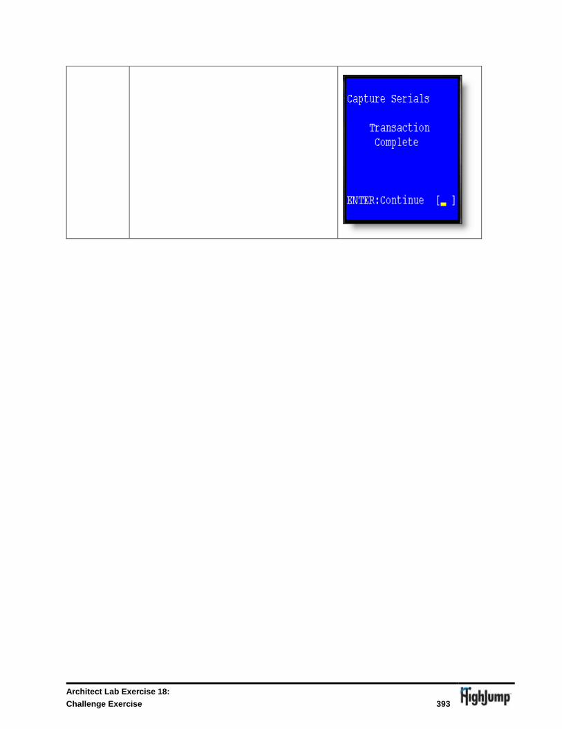
Architect Lab Exercise 18:
Challenge Exercise 393

Architect Lab Exercise 18:
Challenge Exercise 394
Activity 5: Add the Dialogs to the Process
Task: Add the dialogs for the order number, item number, quantity, and serial number to the process. This task assumes no validation on the serial number, no regard for the F1 logic, and no regard for looping.
Order Number Dialog:
There are several business processes in the base application which capture and validate an order number. The business process called Reprint Bill of Lading contains some logic which you can leverage for the order number prompt.
Item Number Dialog:
There are several business processes in the base application which capture and validate an item number. The business process called Adjust by Location contains some logic which you can leverage for the item number prompt.
Quantity Dialog:
There are several business processes in the base application which capture and validate a quantity. The business process called Unload Inbound Order contains some logic which you can leverage for the quantity prompt.
Serial Number Dialog:
Use the skills you learned earlier in the manual to add this prompt.
Pass / Fail Test Case Expected Outcome
Choose the menu option. System displays the Order Number dialog.
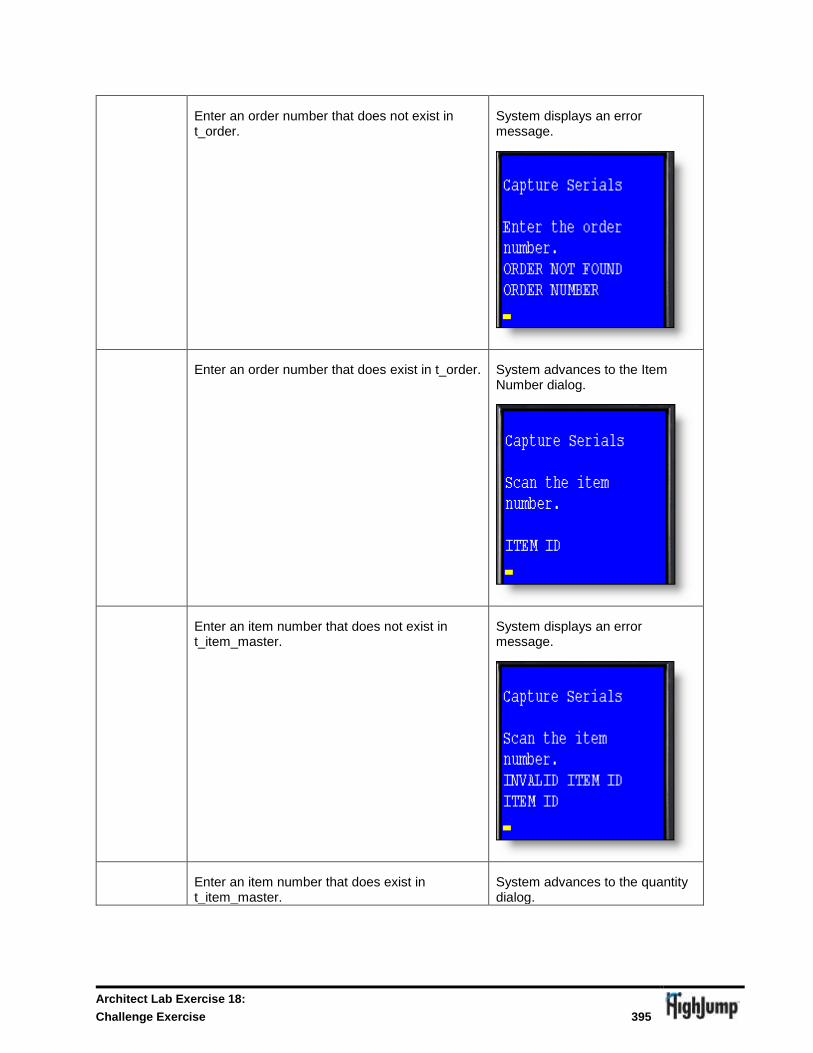
Architect Lab Exercise 18:
Challenge Exercise 395
Enter an order number that does not exist in t_order.
System displays an error message.
Enter an order number that does exist in t_order. System advances to the Item Number dialog.
Enter an item number that does not exist in t_item_master.
System displays an error message.
Enter an item number that does exist in t_item_master.
System advances to the quantity dialog.

Architect Lab Exercise 18:
Challenge Exercise 396
Enter a negative quantity. System displays an error message.
Enter 0 at the quantity dialog. System displays an error message.
Enter a positive quantity. System advances to the serial number dialog.

Architect Lab Exercise 18:
Challenge Exercise 397
Enter a serial number. System advances to the transaction complete dialog.
Press the enter key at the transaction complete dialog.
System advances to the order number dialog.
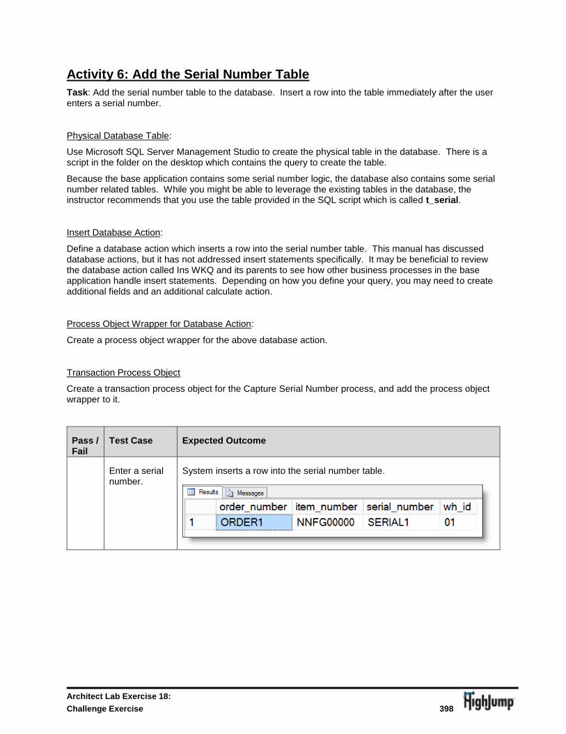
Architect Lab Exercise 18:
Challenge Exercise 398
Activity 6: Add the Serial Number Table
Task: Add the serial number table to the database. Insert a row into the table immediately after the user enters a serial number.
Physical Database Table:
Use Microsoft SQL Server Management Studio to create the physical table in the database. There is a script in the folder on the desktop which contains the query to create the table.
Because the base application contains some serial number logic, the database also contains some serial number related tables. While you might be able to leverage the existing tables in the database, the instructor recommends that you use the table provided in the SQL script which is called t_serial.
Insert Database Action:
Define a database action which inserts a row into the serial number table. This manual has discussed database actions, but it has not addressed insert statements specifically. It may be beneficial to review the database action called Ins WKQ and its parents to see how other business processes in the base application handle insert statements. Depending on how you define your query, you may need to create additional fields and an additional calculate action.
Process Object Wrapper for Database Action:
Create a process object wrapper for the above database action.
Transaction Process Object
Create a transaction process object for the Capture Serial Number process, and add the process object wrapper to it.
Pass / Fail
Test Case Expected Outcome
Enter a serial number.
System inserts a row into the serial number table.

Architect Lab Exercise 18:
Challenge Exercise 399
Activity 7: Add the Serial Number Validation
Task: Add the logic which validates that the given serial number has not been previously scanned. Database Action: Create a database action which selects a row from the serial number table for a given serial number. Process Object Wrapper: Create a process object wrapper for the above database action. Verification Process Object: Create a verification process object which calls the above process object wrapper. The verification process object returns PASS if the serial number is valid and FAIL otherwise. Business Process: Add the verification process object to the dialog-centric process object for the serial number.
Pass / Fail Test Case Expected Outcome
Enter a serial number that has been entered previously.
System displays an error message.
Enter a serial number that has not been entered previously.
System displays the Transaction Complete dialog.

Architect Lab Exercise 18:
Challenge Exercise 400

Architect Lab Exercise 18:
Challenge Exercise 401
Activity 8: Add the Looping Logic
Task: Add the logic which loops on the serial number dialog. Every loop has four components:
Initialize the counter
The “work” inside the loop
Increment the counter
Check to determine if loop should continue or exit There are several examples of looping in the base application. Review the process object called Ship by Load – Event Shipped to see one example of how the application handles loops. In the case of the serial numbers, the “work” inside the loop should include the prompt for the serial number and it should include the insert into the database table. Exiting the loop should be based upon whether or not the system has captured the appropriate number of serial numbers from the user.
Pass / Fail
Test Case Expected Outcome
Enter 3 at the Quantity prompt
System advances to the Serial Number dialog.
Enter the first serial number.
System writes the serial number to the serial number table and continues with the Serial Number dialog.
Enter the second serial number.
System writes the serial number to the serial number table and continues with the Serial Number dialog.

Architect Lab Exercise 18:
Challenge Exercise 402
Enter the third serial number.
System writes the serial number to the serial number table and continues with the Transaction Complete dialog.

Architect Lab Exercise 18:
Challenge Exercise 403
Activity 9: Insert a Row into the Transaction Log
Task: At the end of every serial number loop, insert a row in the t_tran_log table which contains all of the information entered by the user. Log Process Object and Log Fill Calculate Action Create a log process object which executes a log fill calculate action. Incorporate both of these components into the transaction process object.
Pass / Fail
Test Case Expected Outcome
Enter a Serial Number
System writes a record to the t_tran_log table containing the order number, item number, quantity, and serial number.

Architect Lab Exercise 18:
Challenge Exercise 404
Activity 10: Add the F1 Logic
Task: Based upon the requirements, the system should return to the previous dialog when the user presses the F1 key. The exception is on the serial number dialog, which should not accept the F1 key.
Pass / Fail Test Case Expected Outcome
Press F1 at the Quantity dialog. System returns to the Item Number dialog.
Press F1 at the Item Number dialog. System returns to the Order Number dialog.
Press F1 at the Order Number dialog. System returns to the main menu.
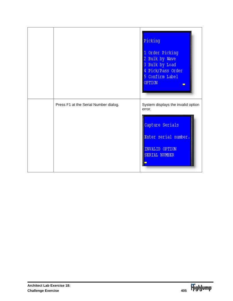
Architect Lab Exercise 18:
Challenge Exercise 405
Press F1 at the Serial Number dialog. System displays the invalid option error.

Architect Lab Exercise 18:
Challenge Exercise 406
Activity 11: Add Text to the Serial Number Dialog
Task: Modify the serial number dialog so that it displays the text “Scanning 1 of x”, “Scanning 2 of x”
Pass / Fail Test Case Expected Outcome
Enter 3 at the Quantity prompt System advances to the Serial Number dialog and displays the text “Scanning 1 of 3”
Enter the first serial number. System advances the Serial Number dialog and displays the text “Scanning 2 of 3”
Enter the second serial number. System advances the Serial Number dialog and displays the text “Scanning 3 of 3”

Architect Lab Exercise 18:
Challenge Exercise 407
Enter the third serial number. System continues with the Transaction Complete dialog.

Architect Lab Exercise 18:
Challenge Exercise 408
Activity 12: Write Entry to the Platform Log
Task: After all serial numbers are captured, write an entry to the platform log with the following syntax: User [user] captured [x] serial numbers for order number [order] and item number [item].
Pass / Fail
Test Case Expected Outcome
Enter 3 at the Quantity prompt followed by the values of 3 unique serial numbers.
System writes one message to the platform log. (You can view the message through Advantage Commander or the Application Status Console.)

Architect Lab Exercise 18:
Challenge Exercise 409
Activity 13: Full Unit Test
Task: You have completed all of the requirements and you have tested each block of changes individually. However, you have not performed a full unit test. It is possible, that one of the changes you made in a later activity broke something from an earlier one. To complete this exercise, review the requirements at the beginning of this exercise and validate that your solution meets all of the requirements.