highly-charged heavy-ion production with short …/67531/metadc686641/...highly-charged heavy-ion...
TRANSCRIPT

UCRL-JC-129617 PREPRINT
Highly-charged Heavy-ion Production with Short Pulse Lasers
G. Logan, T. Ditmire, M. Perry, 0. Anderson, T. Kuehl
This paper was prepared for submittal to the High Power Laser Study Group Workshop
GSI, Darmstadt, Germany January 29-30,1998
January 27,1998
Thisisapreprintofapaperintendedforpublicationinajoumalorprocee~gs. Since changes may be made before publication, this preprint is made available with the understanding that it will not be cited or reproduced without the permission of the author.

DISCLAIMER
This document was prepared as an account of work sponsored by an agency ofthe United States Government. Neither the United States Government nor theUniversity of California nor any of their employees, makes any warranty, expressor implied, or assumes any legal liability or responsibility for the accuracy,completeness, or usefulness of any information, apparatus, product, or processdisclosed, or represents that its use would not infringe privately owned rights.Reference herein to any specific commercial product, process, or service by tradename, trademark, manufacturer, or otherwise, does not necessarily constitute orimply its endorsement, recommendation, or favoring by the United StatesGovernment or the University of California. The views and opinions of authorsexpressed herein do not necessarily state or reflect those of the United StatesGovernment or the University of California, and shall not be used for advertisingor product endorsement purposes.

Highly-charged heavy-ion production with short pulse lasers
Grant Logan, Todd Ditmire, Mike Perry Lawrence Livermore National Laboratory*
Oscar Anderson Lawrence Berkeley National laboratory
Thomas Kuehl GSI, on leave at LLNL
High power laser study group workshop GSI, Darmstadt, Germany
Jan. 29-30, 1998
* Work performed under the auspices of the U.S. Department of Energy by the Lawrence Livermore National Laboratory under contract number W-7405-ENG-48

Laser-plasma source for hicrhlv charned ion beams G. Logan, T. Ditmire, M. Perry, T. Kuehl, 0. Anderson January 26,1997 Introduction: This MathCAD document describes a possible approach using a PW -class short pulse laser to form a useful number (1012) of high and uniform charge state ions with low ion temperature (<< 100 eV) and low momentum spread @p,/p, < IO-4 ) for injection into heavy-ion fusion accelerators. As a specific example, we consider here Xenon+zs, which has an ionization energy Ei - 860 eV for the 26th electron, and a significantly higher ionization potential of 1500 eV for the 27th electron because of the M-shell jump. The approach considered here may be used for other ion species as well. The challenge is not simply to produce high charge states with a laser (the ITEP group [Sharkov] have used long pulse CO2 lasers to create many charge states of chromium up to helium-like Cr+25 by collisional ionization at high Te), nor just to create such high charge states more selectively by field (tunneling) ionization at higher intensities and shorter pulses. Rather, the challenge is to create a selected uniform high charge state, in useful numbers, while keeping the ion temperature and momentum spread small, and avoiding subsequent loss of ion charge state due to recombination and charge-exchange with background gas atoms during extraction into a useful low emittance beam. The general scheme considered here is illustrated in Fig.1 below.
Anode plate potent ial (b, varied in time to (a) joule hei at electrons to
n
Coils form tapered solenoid field to direct ion flow Focusing solenoid acts
con*+ ra~rrmkEn~+ ,. I-VIIIUIII~~on, (b) control As.l+l” llvaulig potential to toward extraction grids and nstbnn inn avoid wall recombination I
as a hollow cathode,
hni --IMV -9m.w w., .v.. / I I .
extraction 44 /I I
It 1
ex --look-
Xe+26 beam
Xenon ion beamlets extracted and
Frozen Xenon -’ \ merged into a large beam - few
-6 -10 em radius amperes total current
,d Q - 5 Hz, I2 Xenon atoms. Concentric annular extractor
/ 0.4 - 0.5 pm, 4OtO4OOfS, -1 PW laser,
-6Ht
Low energy laser pre- pulse shocks pellet Into 1 eV gas, expanded to 10-1to10’3n,before main laser pulse.
grids, pulsed negative to tjbex for - 1 ps to extract Xenon
Ions. Grids radially offset to control beam aberrations.
Fig. 1 Conceptual method of extracting highly-charged ions ionized by a short-pulse laser.
Page 1

Concept: The key features of the concept depicted in Fig. 1 are: (1) illumination of injected targets
within a few tens of microns super-gaussian laser focal spot, such that all atoms see a uniform laser intensity for field (tunnel) ionization to the same chosen charge state, (2) use of a tapered (conical) magnetic solenoid to adiabatically convert transverse ion motion during plasma expansion into parallel ion motion towards the extractor grids, (3) a biased anode plate to both joule heat plasma electrons in the chamber with a discharge current to prevent recombination late into the expansion of the target laser plasma, and to control the plasma floating potential to gate-on the ion extraction through the grids, and (4) use of a set of small annular ion extraction grids radially offset to correct for beam aberrations during merge of the beam annuli into a high voltage ion diode with a focusing solenoid/cathode (This beam extraction scheme was originally suggested by Oscar Anderson, to be published).
One of the authors (T. Ditmire) has recently calculated the laser intensity at 400 fs and 0.5 pm wavelength, corresponding to a frequency-doubled Nd: glass Petawatt CPA laser, that optimizes the field ionization production of Xe+zs (calculations to be published). An optimum laser intensity
I v ‘= d9 W/cm2
is found to achieve >99% of all ions in +26 charge state. At lower intensities of 4 x 101s W/cm2, only 45% of the ions are at +26 charge (the rest being in lower charge states), and at higher intensities of 2 x 10¹⁹ W/cm2, only 82% of the ions are at charge state 26, the rest being at +27 or higher. For a goal of creating better than 90% of the heavy ions at +26, these results illustrate the desirability of illuminating all target gas atoms within a super-gaussian focal spot with a local rms uniformity of intensity better than plus or minus 20 %. The associated electron temperature due to the field ionization at 101s W/cm2 and at 0.5 pm was calculated to be comparable to the 26th ionization potential:
Tea ‘= 860 W)
The laser intensity required for a given ionization level is weakly dependent on wavelength, but the initial temperature scales roughly with hz, so that lf one used frequencydoubled Ti:Sapphire at 400 nm, the Te would be 30 % lower. Conversely, if one uses 1 micron wavelength, Te would be over 3 keV, enough to cause further impact ionization of the remaining M-shell electrons. For the minimum pulse of 400 fs with a Nd:glass CPA, there can still be significant additional collisional electron-heating after ionization (leading to subsequent higher collisional ionizations above +26), at high densites like 0.1 critical (calculations by Ditmire are in progress). Such heating can be minimized either by using lower densities (e.g., 0.01 critical or lower), or by shortening the pulse (e.g., to 40 fs using Ti:Sapphire). Assuming either case, we might neglect such collisional heating. Still, the primary concern to how to get a low ion temperature and velocity spread in the extracted ions, that is, how to prevent a significant fraction of the above initial electron energy, still rather high, from being transferred to the high-charge state ions before they can be extracted into a beam. While the laser does not directly heat the ions significantly during the ionization process, we will find below that electrostatic forces confine the electrons to the close vicinity of the large ion bunches as we consider here, until the bunch density drops by very large volume expansion ratios, such that electrostatic grids as shown in Fig. 1 can separate the ions from the electrons into a useful beam. Because the Debye length will typically be small compared to the ion bunch dimensions, laser pondoromotive forces cannot expel1 electrons, except for very small Ion bunches, too small for accelerator use.
Page 2 h

As a consequence of having overall charge neutrality, one faces two mechanisms that can transfer the significant electron energy invested by the laser during the ionization process to the ions: (1) electron-ion coilisional energy equilibration during subsequent expansion of the large ion bunches, and (2), randomization of the directed ion radial motion imparted by the electron’s electrostatic forces during expansion, by ion reflections from the magnetic fields in the source volume after initial expansion. In effect, the plasma expansion driven by the electron energy is transferable to radial ion energy by the electrostatic coupling, and the subsequent randomization of the radial ion motion in the plasma chamber of Fig. 1 can result in a final ion temperature comparable to q times the initial electron temperature. For good extracted ion beam quality (low ion beam emittance), it is desirable to limit the extracted ion beam temperature in the transverse direction as much as possible (more velocity spread can be tolerated in the parallel direction). For this reason, the solenoid field surrounding the laser plasma in Fig. 1 is tapered so that the laser plasma, which is of high magnetic Reynolds number, can be adiabatically guided in the later phases of the expansion into predominately parallel ion motion. As we will find in estimates given below, line radiation cooling rates slow down as Te falls much below the M-shell excitation levels, and so radiation cooling becomes unimportant as Te fails below a few hundred eV.
Two conceivable ways of preventing or reducing electron energy transfer to the highly charged ions after laser ionization are: Method (I)- try to cool the hot electrons by electron conduction heat loss before the heavy-ion plasma can expand, such as by embeding the heavy-ion target in a pre-formed colder background plasma with Te,ccTe,, to allow cold background plasma electrons to flow into the hotter, denser heavy-ion plasma, in effect exchanging hot electrons with colder ones, while maintaining overall charge neutrality; Method (2)- add a layer of sacrificial hydrogen around the heavy-ion core, so that hot electron expansion energy goes preferentially into accelerating protons rather than the heavier ions, which would be tend to be left behind in the core. As the characteristic plasma expansion speed scales as (q Te, / Mr )O.s, where q is the ion charge state in units of the electron charge, and Mr = M, A is the ion mass, one can show that the ratio of the characteristic conduction cooling time from (1) to the radial expansion time of (2) , with TeO=TeC, scales roughly as as
%on ‘%?xp - (q / 2)0es(ne,,/ ne,,,,)(me 1 Mr)‘*‘(Te, / TeJ”m5
For ner,,,t m 101s cma, and with reasonable limits (e.g., 1014 cm-3) on the background cold electron density in the ion source volume, the above ratio of coolingtimes are large compared to unity. As for approach (2), we have examined the effect of adding hydrogen outer layers, and find such to have a small benefit to cooling electrons, not enough to be worth the complication of dealing with such composite targets, and the problem of having significant parasitic proton currents in the extracted heavy-ion beam.
The plasma volume expansion ratios we are considering are of the order of IOe to fill the plasma plenum volume shown in Fig. 1. By the ideal gas expansion law (assuming no recombination takes place and radiation is neglected) pW u const, and using p=nT, conservation of particles nV = const, and taking y = 93, we get TV?‘-1 = const, or T - V-m . Thus, for a volume expansion ratio of 1 W, one would expect the electron temperature to drop due to expansion cooling by up to a factor of 104. in fact, a I-D radial expansion model later in this paper will show that recombination will occur at some point where Te drops below -few eV, without some auxiliary heating such as by an auxiliary long-wavelength laser or a discharge current, to keep Te above - few eV during the latter part of the plasma expansion.
Page 3

Analysis:
MP ‘= 1.670 1O-27 (kg) the mass of a proton,
me ‘= 9.1.10w3’ (kg) the mass of an electron,
c := 3. lo8 (m/s) the speed of light,
&O := 8.85. lo- I2 Vacuum permittivity (Farads/m),
PO ‘Z 4.x. 10-7 Vacuum permeability (Henrys/m)
e := 1.6~10-‘~ (C) electron charge,
Number of ions per pulse for heavy-ion induction accelerators
We take as a goal the delivery of N z := 5-10” Xenon ions at charge state q := 26 per pulse per beam for heavy-ion fusion applications. For 100 beams in parallel, or 100 pulses stacked into storage rings and accelerated by a total of 2x10⁹ volts, this number of ions per pulse is sufficient to deliver a total beam energy of
100.qae.N z.2. lo9 = 4.20 lo5 Joules,
more than sufficient for fast ignition of pm-compressed DT cores with pr =4 g/cm2 @ p = 250 g/ems, assuming the final beams have sufficiently low transverse and parallel velocity spreads to be focused within less than 160 micron radius spots, and pulse compressed to within - 100 ps at the target (D. Callahan). The short final pulse durations for fast ignition require short extraction pulses at the source of - 1 ps, resulting in an injection current of 2 amperes per beam. The ion range is - 3 g/cm2 for 50 GeV Xenon ions in this fast ignition regime. For distributed-radiator HIF targets (Tabak) with -0.3 g/cm2 ion range, 2.1 GeV Xenon at q = 8 is more appropriate, where the required number of ions per beam would be -100 times larger, or Nr - 5x10¹³ ions per pulse to deliver a total of 5.9 MJ. With longer 10 psec injected beam pulses, the required injector current per beam would be 22 amperes, and the allowed spot radius is also 17 times larger, with a final pulse duration at the target 80 x longer. The following examples will be appropriate for fast ignition cases with the above defined number of 5x10¹¹ ions per pulse. c Xenon oellet
To account for various losses and to minimize depletion effects on the extracted beam current, one must create some multiple K times Nx,:
KZ := 2 , for example, so that the number of source ions that must initially be created per beam per pulse is
Nm(Nz) := tciNz N &N z) = 1*1012 source ions per pulse. Eq. 1
The mass per pellet that contains this number of ions at mass A := 131
M,(N.,A) := N m N, .A*Mp ( > M&N z,A) = 2.2* lo-l3 &I)* Eq.2
Page 4 h

At a frozen mass density of Xenon pzo := 2700 kg/ma, the radius of a spherical frozen pellet that contains the desired number of atoms is
3-M Zo(N Z,A) o.333
4-T zo r,(N .,A) = 2.7*10* (p).
The corresponding atomic density in the frozen Xenon core of the pellet is
Eq. 3
n,(N,,A) ‘= 4 Nzo(Nz) -.przo(N z,A)3
n,(N Z,A) = 1.2*1028 atoms/m3 Eq. 4
3 or n ‘OcN z9A) = 1.2. 1()22 atoms/cm3
lo6 A laser pm-pulse is assumed to shock such a composite pellet into a 1 eV gas, which is
subsequently allowed to expand until the atomic density has fallen to some chosen fraction x of critical density for laser propagation. Because of the high final charge state of the Xenon ions, it is the Xenon core density, rather than the outer hydrogen mantle, that determines the maximum electron density in the pellet for a given x. We will consider a range of x to contol the initial electron density, the degree of collisional-laser electron heating and recombination rate subsequent to ionization: For j ‘= 1.. 16 steps of decreasing target Xenon gas densities, starting at ntit
xj := 1o- 0.24 - 1) -4owest x is Q6 = 1*lo-3
the corresponding Xenon core gas (ion) densities considered (just before the main laser pulse) 27
ll,i(X,q,h) I= x’ q-n2
(m-s), where h is the laser wavelength in microns. Eq. 5
The radius of the Xenon gas core at the point where the desired density is reached (just before the main laser pulse arrives to ionize the gas), is given by
Eq. 6
Reauhd laser Dower and enemy
Since the hydrogen will ionize easily at the laser intensities required to ionize the Xenon core, and since the hydrogen layer is thin compared to the Xenon core radius, we can set the superqaussian equivalent “flat top” radius equal to the Xenon core radius to estimate the laser power required at I, intensity:
P~(Iv,Nz,A9X,qt~) := ~.rzi(Nz,A,~,q,X)2.104.1, Watts Eq. 7
where we have used 104 IU because IU is expressed in W/cm2 by convention. The corresponding laser energy depends on the shortest pulse ‘5” achievable for a given type of laser and wavelength:
Page 5 h
EL(I”J” J’Jz,&x,qJ) := PL(IVJ’JzA,x,q+v (Joules)
in general, the absorbed energy laser energy ELa for the ionization and heating of electrons from Xenon and hyrdogen will be very small, conservatively estimated as
Eq. 8
E La(N ,,E i,Te o) ‘= 9-e. 0.5.E i + “.Te 2 O *N ZO(N z) Eq. 9
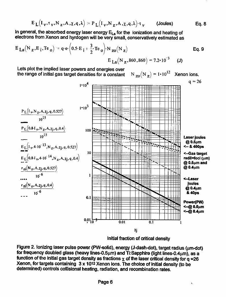
Lets plot the implied laser powers and energies over the range of initial gas target densities for a constant N Zo(N z) = 1*1012 Xenon ions.
. ..^ 4 q =26 I’IU
EL I,,4.10 ( -13,N,,A,~j,q,0.527 @ O.&m
<- & 4oops em
10 /
E~(0.8~1,,4~10- l4 <-Gas target
,Np&Xj,q,O.4 ) I I I I,, radikfoci (pm)
-- @ O&pm and @ 0.4pm
lO-6 . . . . G-Laser joules
lO-6 8 O-&m &ws
1
0.1 -mm
100
E La(N .,860,860) = 7.2*10-3 (J)
MO3
Laser joules
Power(PW) <-@ O.&m *-@ 0.4Fm
Initial fraction of critical density
Figure 2. Ionizing laser pulse power (PW-solid), energy (J-dash-dot), target radius (urndot) for frequency doubled glass (heavy lines-O.5pm) and Ti:Sapphire (light lines-O.4pm), as a function of the initial gas target density as fractions x of the laser critical density for q =26 Xenon, for targets containing 3 x 10¹² Xenon ions. The choice of initial density (to be determined) controls collisional heating, radiation, and recombination rates.
Page 6 h
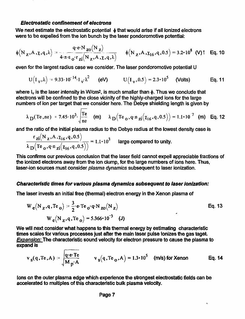
Electrostatic confinement of electrons We next estimate the electrostatic potential Q that would arise if all ionized electrons were to be expelled from the ion bunch by the laser pondoromotive potential:
+(N ,,A,x.4&) := (I-N zap z) 4.n.E o*rzi(N ,,A,X,q,h)
tj(Nz,A,X16,q,0.5) = 3.2*108 o/)! Eq. 10
even for the largest radius case we consider. The laser pondoromotive potential U
U(1 “,h) ‘= 9.33.10- 144 ,.h2 W) U(I .,0.5) = 2.3*105 (Volts) Eq. 11
where I, is the laser intensity in W/cm2, is much smaller than $. Thus we conclude that electrons will be confined to the close vicinity of the highly-charged ions for the large numbers of ion per target that we consider here. The Debye shielding length is given by
and the ratio of the initial plasma radius to the Debye radius at the lowest density case is
rzi(Nz~A9X169q90*5) = 1 1alo3
0.5)) - large compared to unity.
This confirms our previous conclusion that the laser field cannot expeli appreciable fractions of the ionized electrons away from the ion clump, for the large numbers of ions here. Thus, laser-ion sources must consider plasma dynamics subsequent to laser ionization.
Characteristic times for various plasma dynamics subsequent to laser ionization:
The laser invests an initial free (thermal) electron energy in the Xenon plasma of
W e(N z,q,Te o) := i.e.Te o.qN m(N z) Eq. 13 c
W ,(N z,q,Te o) = 5.366*10w3 (J)
We will next consider what happens to this thermal energy by estimating characteristic times scales for various processes just after the main laser pulse ionizes the gas taget. ExDansion: The characteristic sound velocity for electron pressure to cause the plasma to expand is
v,(q,Te,A) := J
f$$ P’
v,(q,Te.,A) = 1.3405 (m/s)forXenon
Ions on the outer plasma edge which experience the strongest electrostatic fields can be accelerated to multiples of this characteristic bulk plasma velocity.
Page 7

in what follows, we will evaluate examples as we go along using a particular valuq,, = 0.01 Later on, we will plot all the characteristic times over the range 1’ x >I03 .
The characteristic expansion time for the plasma radius to double, neglecting other effects such as equilibration and radiation loss, is
‘I zexp(Nz,A,X9q.Te o,h) := rzi(Nz,A9X9q,h)
vs qJe,,A ( > (s)
~zexp(Nz,A,~11,q,Teo,0.5) =4.2*10-” w-
Ion-electron equilibration
Coulomb logarithm Lnh(Te,ne) ‘= In 12.n;. (
-1 1.5 c ..Te.e ) +l
neos5
Electron-ion energy equilibration time
3 2. 1014.A.Te”5 zueqi(q,A,Te,ne) := ’ ne. q2. Lnh( Te , ne)
[Te in eV, ne in m-31
w
TUeqi 99 ( A,Te09q-~zi(X11 ,q90a5)) =3.5*109 6)
Collisional ionization and recombination
First, we need to check some charateristic rates for atomic processes to see how far such a laser plasma is created from equilibrium between coiiisional ionization and recombination at q =26.
The coliisional three-body recombination time (Zel’dovich and Raizer, “Physics of Shock Waves and High-Temperature Hydrodynamic Phenomena”, Academic Press,1 966,Voi. 1, page 407, Eq. 6.104) is
Eq. 15
Eq. 16
Eq. 17
r2er(Te,q,m) := Te4s5
8.75. 10-39.q5d (s), with Te in eV, nz in m-s
Eq. 18
E.g., 12er(Teo~q~nzi(Xi1~q ,0.5)) = 6.50 1O-5 (s), @
“zi X*1*9, ( 0.5) = 1.50 1O24 (m-3)
Page 8

The radiative recombination time (Zel’dovich and Raizer, “Physics of Shock Waves and High-Temperature Hydrodynamic Phenomena”, Academic Press,l966,Vol. 1, page 405, Eq. 6.100) is
7 ewUe,q,W := Te0.75
2.7. lo- ‘9.q3az (s), with Te in eV, Eq. 19 nz in m-3
Oevr (Te,vq,n,i(X,l 94 ,o.s)) =2.2*10-*(s), @ “zi X1194, ( 0.5) = 1.56 1O24 (m-3)
The total recombination time is
zrec(Te,q,m) := (~2er(Te9q,~)-’ + ~ewCTe,q,nz)ml)m* w Eq. 20
z ret (Te.,q~n~i(X~~ 39 ,os)) = 2.2*10-* (s), @ “zi X11999 ( 0.5) = 1.5*1024 (m-s)
The time to double the initial electron density by collisional ionization (Post, Jensen, Tarter, Grasberger and Lokke) PPPL report-1352, July, 1977) page 71, Eq. 82) of the next bound (M-shell) electron with Ei = 1500 eV is given by
z ion(Ei ,Te ,m) ‘= 1.86. 10m7.(nz 10-6).(Te. 10m3)os5.exp
Zion ( 1500,Teo9nzi X11 ,q, ( 0.5)) = 1.6*10-7 (s), @ “zi X1139, ( 0.5) = 1.50 1O24 (m-3)
We note already that because Q,,,>>T,>> rzexpr that the laser plasma as created is not, at least initially, in coronal equilbrium, that is, that the rate of change of charge state will lag behind the rate of change of Te.
Radiation coo/inq .
First we check to see if the laser plasma is optically thick or optically thin. The Rosseland mean-free-path for these conditions (Zel’dovich and Ralzer, “Physics of Shock Waves and High-Temperature Hydrodynamic Phenomena”, Academic Press,l966,Vol. 1, page 279, Eq. 5.56) is given by:
Eq. 22 hR(Te,nz,q,Ei) := 1.1~1023~10~2~(Te~11600)3’5
(nzd)**q.(q + 1)2Q ; ( 1
h12(Te o~nzi(xll pq ,0.5) ,q,860) = SolO4 (m), which Is far larger
than the radius of the Xenon plasma. This means that radiation cooling by line, bremsstrahlung, and recombination free-bound continuum will be in the opticaly-thin iimit.
Page 9 h

For a steady state coronal equilbrium, where the average ion q is determined by collisional ionization balanced by recombination, Post, Jensen, Tarter, Grasberger and Lokke (PPPL report-1352, July, 1977 page 47) calculate an average ion q =26 is achieved in equilibrium at an electron temperature of -1 keV. This indicates that a laser plasma created at q=26 and at a lower temperature Te, < 1 keV is not in equilibrium, and since the recombination times estimated above are long compared to plasma expansion times, one expects the the plasma will remain in non-equibrium during the expansion. In this case we need to estimate radiation cooling by line radiation from collisional excitation of the nearest M-shell bound state which can be excited only by a small fraction of the electron distribution tail. Take, for example, an n=2 transition to the ground state of the adjacent bound shell (M-shell) for a q = 26 Xenon ion. The ionization level for the 27th electron is 1.5 keV, so we estimate the n=2 energy level to be w 0.74 En -1100 eV.
For a given ion charge state q and associated dominant energy level En in the M-shell bound states excited by electron collisions, the ratio of the collisional excitation rate at a given value of electron temperature Tel to that at a higher temperature Te2 is
R cex( En ,Tel ,Te2) 1= (gr”-e*p($ - &) Eq. 23
At Te2 = 1000 eV, where the equilibrium charge state of Xenon would be the same at q= 26, the radiation cooling rate L,- 1.8*1 O-18 ergs per electron per ion by the Post et.al. reference given above, from all excited states and radiative transitions. At the lower initial Te, created by the laser ionization, the excitation rate would be lower by a factor of
R cex (1100 ,Te o, 1000) = 0.775
Extrapolating from the equilibrium radiation rates with this ratio, one estimates a cooling rate at Teo of (in the Post, et. al. units of IO-19 ergs-cm3 secl per electron per ion)
R Ct?X (1100,Teo,1000)~l.8~10~18 = 14
lo- l9
From the collisional excitation rate at TeO for the En = 1100 eV transition, a direct calculation, using Eq. 818 on page 75 in the Post et.al. reference above-with an oscillator strength fi2 = 0.585 and a Gaunt factor of 2, gives
L (En Te) := 4 99. 10-10~(Te*10‘3)-o*5. z ’ .
Lz(llOO,Teo > = 4.8 This is within a factor of 3 of the extrapolation lo- l9 from the Post curves. This estimate should be a
bit low because we have included only the principle n=l to n=2 transition.
Page 10
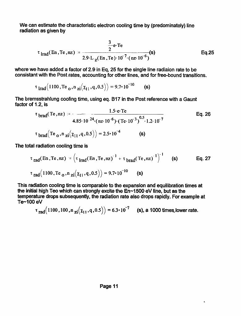
We can estimate the characteristic electron cooling time by (predominately) line radiation as given by
3 -. e. Te zhd(En,Te,nz) := 2
2.9-L z( En ,Te)* 10e7*( rm 10e6) (s) Eq.25
where we have added a factor of 2.9 in Eq, 25 for the single line radiaion rate to be consistant with the Post rates, accounting for other lines, and for free-bound transitions.
1 had llOO,Te 09nzi i ( X11,9, 0.5)) = 9.7* lo-‘O (s)
The bremsstrahlung cooling time, using eq. B17 in the Post reference with a Gaunt factor of 1.2, is
Tbmd(Te,IIZ) := 1.5.e.Te 0.5
Eq. 26 4.85-10~24~(nz~10‘6)~(Te~10-3) *1.2*10-7
Tbmd Teo,nzi ( ( X11,4, 0.5)) = 2.5* 1O-4 (s)
The total radiation cooling time is
zrad(En,Te,nz) ‘= z Irad(En,Te,nz)-* + Zbrad(Te,m)-l (s) Eq. 27
~~~~(1100,Te~,nzi(X11,q,0.5)) =9.7*16’” (S)
This radiation cooling time is comparable to the expansion and equilibration times at the initial high Teo which can strongly excite the En-1500 eV line, but as the temperature drops subsequently, the radiation rate also drops rapidly. For example at Te-100 eV
7 rad( 1100,100 ,n zi( X1 1 ,q ,0.5)) = 6.30 lo-’ (S), a 1000 times,lower rate.
Page 11

Characteristic time scales versus x N Zo(N z) = 1*1O12 Xenon ions. q = 26
l*1o-8
Lqi(q,A,Te .,q-n zi(Xj,SvOJ))
Td( 1100,Te o,n zi(XjIq90.5)) le109 --
Tion(*500,Teo,nzi(Xj,q,0.5)) . . . .
l*lO-lo
1*10-1;. 10 = 0.01 0.1
x.i
[All times shown in seconds ]
Collisional ionkation
Recombination
<-Expansion (radius by 2x)
Equilibration
1 Radiation cooling
Initial fraction of critical density Fig. 3 Character%& time scales (seconds) for the laser plasma just after laser field ionization versus initial fraction of critical density for half-micron wavelength for various plasma processes: Xenon plasma expansion (thin solid line), ion-electron temperature equilibration (thick solid line), radiation cooling time ( thick dashed line), recombination time (dash-dot line), and collisional ionization time (dotted line).
Figure 3 shows indicates that, lf one wants to use radiation cooling to dispose of excess electron energy before expansion takes place, that one wants to have the laser pulse ionize at high initial density (x) > 0.1 times critical, and considering Fig. 2, this also keeps the initial gas target radius small and minimizes laser power and energy. However, the radiation cooling rapidly subsides during the subsequent expansion, and cannot, by itelf, reduce the electron temperature to much below a few hundred eV while the ion charge state remains at high levels. In addition, starting at a higher density increases the three-body recombination rates, making it harder to avoid recombination as Te falls,
Page 12

Higher initial density raises the electron temperature during the subsequent expansion at which point recombination will occur without auxiliary discharge heating to keep Te above the recombination temperature (generally around a couple of eV). Recall that during an adiabatic expansion of the volume V, T * V-m, while n u V-1, such that the three-body recombination time by Eq. 22, zzer w T4.5 / n2 -, V-1 eventually becomes shorter than any other time scale at some point in the expansion over large volume ratios. If that point occurs at too high a density, it becomes very difficult to apply sufficient auxiliary heating to prevent further electon temperature decline leading to rapid recombination. The following section develops a crude (quasi-l-D ) model of the expansion dynamics to determine when recombination will set in as a function of the initial density, and to determine what ohmic current density from a low-power discharge is required to prevent recombination.
Quasi I-D model of the laser plasma expansion
In what follows, we will1 assume a laser wavelength k .= 0.5 pm
Effective electron energy gain (E3) per recombination : [Latyshev & Roudskoy, Fiz. Plasmy II, 1175,
(19W E 3(Te,q,ne) :=
OA7 (eV). Eq. 28
The three-body recombination coefficient (as in Eq. 18) a 3Ue ,q> ,=
8.75. lo- 39.q3
Te4’5 (ms/s) Eq. 29
This leads to an electron heating rate due to p je(Te,q,ne) := 0.67.E 3(Te,q,ne).a 3(Te,q)+ne2.q-’ Eq. 30 recombination of:
(in eV per set per electron)
Initial electron densities have to be chosen low enough such that recombination does not occur too quickly. The lower the initial electron density (which, after ionization by the laser, becomes q x naas), the larger is the initial gas radius r, required for a given intial ion inventory Nz, and thus the larger the laser focal spot radius, laser power, and pulse energy required for a given ionization level and laser intensity. This poses the principle trade-off in laser production of high charge state ions: mom laser power required for less recombfnation.
We will now perform a simple MathCAD numerical calculation of a spherical laser plasma expansion for a time zs := 10-8 (s)-
Page 13

We need a variable to control the time step size: giving the
time step growing linearly with k as I: (NzAxll ,q,h)+W-’ “tk ‘= k.hax-‘. ”
vs qJeoA) ( (s) Eq. 32
Check-we get the right expansion time: c is& = 1*1o-8
k
(s), same as zS.
When the initial radius is small, the time step is small: 6t, = 2.50 lo-l3 (set), and grows
longer with the radius near the end of the expansion: S&, = 70 10-l ’ (s).
The following MathCAD iteration routine calculates plasma expansion parameters for the k time-steps:
nel
Y
5
Tel
-1
=I
NZl
%
*1
.- .-
4 --*~rzi(Nz9A,X11 9q9h)3 3
q’ lo3
lo- ”
TeO
1
rzi(Nz9A*X** 9q*h)
Nzo(Nz)
0
Page 14
resulting in kmax = 285 in this example. For k = l..kmax time steps, with each
initial conditions at time step 1
.
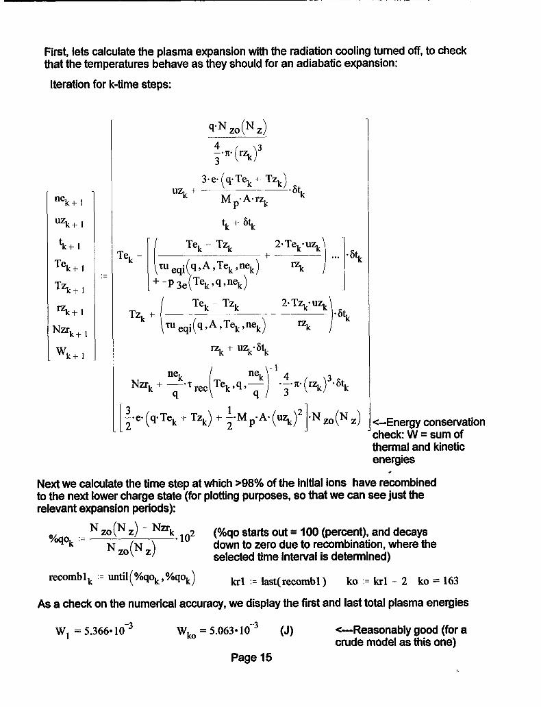
First, lets calculate the plasma expansion with the radiation cooling turned off, to check that the temperatures behave as they should for an adiabatic expansion:
Iteration for k-time steps:
nek+ 1
%+I
‘k+ 1
Tek+ 1
TZk+ 1
%+I
Nmk+ 1
W k+l
.-
q-N zoCN z)
wk +
h+fkk + TZk)sst
Mp.A.% k
tk + 6tk
Te, - Te, - TZ,
l-
~ueqi(9,A,Tek,nek)
-P 3e(Tekvq,ns)
Tz, + i
Te, - TZ, 2. TZ,. Us - ’ 6tk
‘tu eqi (q.A,Tek,nek) =k
=k + ?+k
3 Ze-(qTek t TZk) + iaM PsA’ (uzk)’ ieN mcN z> 1 <-Energy conservation
check: W = sum of thermal and kinetic energies
t Next we calculate the time step at which >98% of the initial ions have recombined to the next lower charge state (for plotting purposes, so that we can see just the relevant expansion periods):
k,-Nm(NZ)-Nmk 2 %qo .--
Nzo(Nz) l lo (%qo starts out = 100 (percent), and decays down to zero due to recombination, where the selected time interval is determined)
recomb1 k := until(%q~,%qok) krl := last(recomb1) ko := krl - 2 ko = 163
As a check on the numerical accuracy, we display the first and last total plasma energies
W, = 5.3669 1 O-3 wko = 5.0630 lo” (J) +-Reasonably good (for a crude model as this one)
Page 15 h

For k .= 1.. ko points, plot the following quantities for the initial condition [ Adiabatic expansion, radiation losses turned off ]
Tek
Tzk --
wk . . . .
0.01
1*lo-3 ldl I* lo-lo
Time after laser pulse (set) - Radius(t) over initial radius of Xenon plasma - Radial expansion velocity (m/s) - - Electron temperature (ev) - - Xenon ion temperature (ev) l *** Total plasma thermal+kinetic energy (J) + - ’ - Percentage of ions NOT recombined (%)
Figure 4: Plasma expansion parameters for 1012 Xenon +26 ions starting out at IO-2 x critical density for 0.5 micron laser light. ( The initial Teo - 860 eV at II,,,= 1 x10¹⁹ W/ cm? Early in time one sees the ions and electron temperatures equilibrate, and then both temperatures fall off with further expansion as would an ideal gas undergoing an adiabatic expansion. Note that expansion cooling of electrons causes recombination to set in after a few ns, well before the ions could be extracted. The total thermal+klnetic energy (W) is nearly constant as it should be for an adiabatic expansion, once the time step (controlled by the KP parameter)is chosen small enough to minimize numerical integration errors. The asymptotic ion velocity corresponds to a kinetic energy - q x the initial electron temperature Teo.
Page 16

Next we repeat the above expansion calculation, but now we add in the effects of line radiation cooling.
Iterating again for k-time steps, with the radiation loss term added to the Te line :
nek+ 1
uzk+l
‘k+ 1
Te k+l
TZk+ 1
%+I
N”k+ 1
Wk+l
,- ,-
rek -
f.n. (rz’J3 UZk+ h+fkk + ‘““).st
Mp.A.~ k
tk + “tk
i
Te, - Ts 2’Te,‘~ 3 + + -* . . .
tUeqi(q9A9Tek9nek) Tzk 2
+-P 3e(Tek.qynek)
TZ, + Te, - TZ, 2. TZ,. Ui$
l” eqi (%A,Te,Wk) - ‘zk - t?tk
ri& + us’ 6tk
.‘
%qo .= N ZO(~ Z) - Nzrk . 1o2 (%qo starts out = 100 (percent), and decays down to
k Nzo(Nz)
zero due to recombination, where the selected time interval is determined)
. “‘k
lV3COIllb2k '= mtil( “/osok, %qok) kr2 := last( recomb2) ko .= kr2 - 2 ko = 146
Again, the initial and final total energy W, = 5.366* loo3 Wko = 4.1*10v3
which now shows the effect of radiation loss
Page 17

Again, we plot the same plasma expansion parameters but this time with radiation loss:
For k = l..ko points, plot the following quantities :
% rzi(Nz.A,xl l,q,h
Tek
Tzk
Time after laser pulse (set) Radius(t) over initial radius of Xenon plasma
- Radial expansion velocity (m/s) - - Electron temperature (ev) - - Xenon ion temperature (ev) c
‘* l * Total plasma thermal+kinetic energy (J) - ’ - Percentage of ions NOT recombined (%)
Figure 6: Plasma expansion parameters versus time for the same conditions as in Fig. 4, but now with line radiation losses included. Note that the radiation loss causes recombination to occur earlier than in the adiabatic case, and also note the plasma energy is decreased by the amount of radiation loss.
Next we will consider the effect of joule heating the electrons by adding a fixed discharge current I, through the expanding laser plasma, as suggested by George Caporaso. The discharge current would be driven by biasing the anode plate shown in Fig. 1. As the laser plasma is created in a good vacuum, the discharge current is assumed to flow through the cross section xr;! of the laser plasma, to determine the resultant ohmic current density as the plasma expands.
Page 18 VI

At the high plasma densities considered here, the classical plasma resistivity can be expected to dominate electron heating, that is anomalous (Buneman-type) electron two-stream resistivity is important only for much lower densities). The classical plasma electrical resistivity is given by (Te in eV):
1 res(q9Te pne) = 5.2. 10w5.q-Lnh( Te ,ne)
Tel*’ (ohm-meters) Eq. 33
In what follows, we assume a fixed discharge current I c ‘= lo3 Amperes. Now, we’ll repeat the expansion calculation with the resistive heating term: For k = 1.. kmax
nek+ 1
uzk+l
‘k+l
Te k+ 1
TZk+ 1
=k+l
N2sk+ 1
W k+ 1
.- .-
rek -
Again, we calculate
kr3 .= last( recomb3 )
uzk + k(@kk + TZk)eFt
Mp.Aq k
tk + “tk
(q,A,Te,$‘=k) ‘“Lk 2
2 recomb3 k .= until ( “/“sok ) %qok)
ko .= kr3 - 2 ko = 283 The final total energy
Wl = 5.4*lo-3 wko = 4.846* 1(i3 does not decrease as much due to the joule heating.
Page 19

For k = l..ko points, plot the quantities (with both radiation loss and joule heating) :
Tek --
Tzk --
wk . . . . “/6qO k -x-
0.01
l*lo-3 ld’
-
a......
l*lo-lo
Time after laser pulse (set) - Radius(t) over initial radius of Xenon plasma - Radial expansion velocity (m/s) -- Electron temperature (eV) - - Xenon ion temperature (eV) ri’ Total plasma thermal+kinetic energy (J)
- Percentage of ions NOT recombined (%) c
Fig. 6 . Plasma expansion parameters for conditions as in Fig. 5, but now with both radiation loss and with joule heating of electrons due to a constant discharge current of I kA flowing through the laser plasma as it expands. Note that the joule heating now prevents recombination of the q=26 Xenon ions, by keeping the electron temperature maintained above -30 eV late in the expansion, when recombination would have otherwise have occurred. The ion temperature continues to cool by expansion, decoupling from the electron temperature. Also note that the total plasma energy first decreases early in the plasma expansion at high density due to radiation loss, but then increases later on due to the joule heating input. Thus, the discharge current is key to allow the highly-charged ions to survive recombination until they can be extracted.
Page 20

Technical Inform
ation Departm
ent • Lawrence Liverm
ore National Laboratory
University of C
alifornia • Livermore, C
alifornia 94551