highly flexible couplings elpex-s series - agp …agp.com.co/pdf/elpex-s.pdf · · 2015-11-19side...
TRANSCRIPT

Siemens MD 10.1 · 2015
11
11
11/2 Overview
11/2 Benefits
11/2 Application
11/2 Design
11/4 Function
11/4 Configuration
11/6 Technical data
11/9 Type ESN11/9 Selection and ordering data
11/10 Type ESD11/10 Selection and ordering data
11/11 Type ESNR11/11 Selection and ordering data
11/12 Type ESDR11/12 Selection and ordering data
11/13 Types ESNW and ESDW11/13 Selection and ordering data
11/14 Type EST11/14 Selection and ordering data
11/15 Spare and wear parts11/15 Selection and ordering data
Highly Flexible Couplings ELPEX-S Series
MD10-1_2014_EN.book Seite 1 Freitag, 31. Juli 2015 6:11 18
© Siemens AG 2015

FLENDER Standard CouplingsHighly Flexible Couplings — ELPEX-S Series
General information
11/2 Siemens MD 10.1 · 2015
11
■ Overview
Coupling suitable for use in potentially explosive atmospheres. Complies with the current ATEX Directive for:
II 2 G T3 D160 °C X
II 2 G T4 D120 °C X
(Type EST is not available in Ex version.)
ELPEX-S couplings are highly torsionally flexible and because of their low torsional stiffness and damping capacity are especially suitable for coupling machines with a highly non uniform torque pattern. Standard ELPEX-S coupling types are designed as flange-shaft-connections or shaft-shaft connections. Application-related types can be implemented on request.
■ Benefits
The ELPEX-S coupling is suitable for horizontal and vertical mounting positions or mounting at any required angle. The cou-pling parts can be arranged as required on the shafts to be con-nected.
ELPEX-S couplings are especially suitable for reversing opera-tion or operation with changing directions of load.
The rubber disk elements are fitted virtually without backlash and give the coupling linear torsional stiffness, i.e. the torsion stiffness remains constant even when the load on the coupling increases.
There are 4 different rubber element versions with different grades of torsional stiffness available for each size from stock.
On certain types the flexible rings can be changed without hav-ing to move the coupled machines.
If substantial overload occurs, the rubber disk element of the coupling is irreparably damaged, the coupling throws the load and thus limits the overload for particular operating conditions. The coupling can be inserted and fitted blind e.g. in a bell hous-ing.
There are outer flanges with different connection dimensions available for each coupling size.
■ Application
The ELPEX-S coupling is available as a catalog standard in 12 sizes with rated torques of between 330 Nm and 63000 Nm.
The coupling is suitable for ambient temperatures of between -40 °C and +120 °C.
The ELPEX-S coupling is frequently used for diesel motor drives or reciprocating compressor drives. Because the different rub-ber versions enable the torsional stiffness to be adjusted to meet requirements, the coupling is also suitable for drives which re-quire a specific and preferably precalculated torsional vibration behavior setting.
■ Design
The rubber disk element is vulcanized onto a flange on the in-side diameter. The flange can mount e.g. a Taper clamping bush or a hub. On its outer diameter the rubber disk element has driv-ing teeth, which are inserted into the outer flange. The torque is transmitted positively between the rubber disk element and the outer flange.
In the type for shaft-shaft connection the outer flange is screwed to a flange hub mounted on a machine shaft.
Materials
Elastomer materials of the rubber disk element
ELPEX-S coupling types
Type EST Types ESN. and ESD.Rubber disk element Grey cast iron
EN-GJL-250/elastomerSpheroidal graphite cast iron EN-GJL-400/elastomer
Hubs, part 1, part 2 Steel SteelOuter flange Cast aluminum
AlZnSi108.. Sizes 680 and 770of spheroidal graphite cast ironEN-GJS-500
Cast aluminum AlZnSi108.. Sizes 680 and 770of spheroidal graphite cast ironEN-GJS-500
Material / description HardnessShoreA
Iden-tifica-tion
Ambient temperature
Natural-synthetic rubber mixture 50 ° … 55 ° WN -40 °C … +80 °CNatural-synthetic rubber mixture 60 ° … 65 ° NN -40 °C … +80 °CNatural-synthetic rubber mixture 70 ° … 75 ° SN -40 °C … +80 °CSilicone rubber 55 ° … 65 ° NX -40 °C … +120 °C
Type DescriptionESN Coupling with hub, long or short versionESD Coupling with hub, with two rubber disk elementsESNR Coupling with hub, rubber disk element radially dismountableESDR Coupling with hub with two rubber disk elements; rubber disk
elements radially dismountableESNW Coupling designed as a shaft-shaft connection with a rubber disk
element; rubber disk element radially dismountableESDW Coupling designed as a shaft-shaft connection with two rubber disk
elements; rubber disk element radially dismountableEST Coupling suitable for mounting a Taper clamping bush
MD10-1_2014_EN.book Seite 2 Freitag, 31. Juli 2015 6:11 18
© Siemens AG 2015

FLENDER Standard CouplingsHighly Flexible Couplings — ELPEX-S Series
11/3Siemens MD 10.1 · 2015
General information
11
Type ESN – long version
Type ESN – short version
Type ESNR
Type EST
Type ESD
Type ESDR
Type ESNW
Type ESDW
Part 3 Part 5 Part 2
G_M
D10
_EN
_000
56
G_M
D10
_EN
_000
16
Part 3 Part 5 Part 2
Part 3 Part 5 Part 2
G_M
D10
_EN
_000
17
Part 3 Part 5
G_M
D10
_EN
_000
18
Part 5 Part 3 Part 5 Part 2
G_M
D10
_EN
_000
19
Part 6 Part 3 Part 5 Part 2
G_M
D10
_EN
_000
20
Part 3Part 1 Part 5 Part 2
G_M
D10
_EN
_000
21
Part 6 Part 3 Part 5 Part 2Part 1
G_M
D10
_EN
_000
22
MD10-1_2014_EN.book Seite 3 Freitag, 31. Juli 2015 6:11 18
© Siemens AG 2015
FLENDER Standard CouplingsHighly Flexible Couplings — ELPEX-S Series
General information
11/4 Siemens MD 10.1 · 2015
11
Further application-related coupling types are available. Dimension sheets for and information on these are available on request.
The following versions have already been implemented a num-ber of times:• ELPEX-S coupling with brake drum, brake disk or flywheel
mass• ELPEX-S coupling with axial backlash limiter• ELPEX-S coupling with adapter• ELPEX-S coupling with bearing for mounting a cardan shaft• ELPEX-S coupling for engaging/disengaging during standstill• ELPEX-S coupling as part of a coupling combination • ELPEX-S coupling with fail-safe device
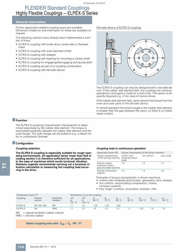
Fail-safe device of ELPEX-S coupling
The ELPEX-S coupling can also be designed with a fail-safe de-vice. If the rubber disk element fails, the coupling can continue operating in emergency mode for a short time. This option is fre-quently required e.g. in the case of marine drives.
If the rubber disk element fails, cams transmit the torque from the inner and outer parts of the fail-safe device.
In normal operation the torsion angle of the rubber disk element is smaller than the gap between the cams, so there is no metal-metal contact.
■ Function
The ELPEX-S coupling's transmission characteristic is deter-mined essentially by the rubber disk element. The torque is transmitted positively between the rubber disk element and the outer flange. The outer flange can be bolted to e.g. a diesel mo-tor or compressor flywheel.
■ Configuration
Coupling selection
The ELPEX-S coupling is especially suitable for rough oper-ating environments. An application factor lower than that in catalog section 3 is therefore sufficient for all applications. In the case of machines which excite torsional vibration, Siemens urgently recommends carrying out a torsional vi-bration calculation or measuring the coupling load occur-ring in the drive.
Coupling load in continuous operation
Examples of torque characteristic in driven machines:• uniform with moderate shock loads: generators, fans, blowers • non uniform: reciprocating compressors, mixers,
conveyor systems• very rough: crushers, excavators, presses, mills
NR = natural-synthetic rubber mixtureVMQ = silicone rubber
G_M
D10
_XX
_000
23
Application factor FB Torque characteristic of the driven machineTorque characteristic of the driving machine
uniform with moderate shock loads
non uniform very rough
Electric motors, hydraulic motors, gas and water turbines
1.0 1.3 1.4
Internal combustion engines
1.3 1.4 1.6
Temperature factor FT Temperature Ta on the couplingCoupling Rubber
versionElastomer material
-40to-30 °C
-30to+50 °C
to 60 °C
to70 °C
to80 °C
to90 °C
to100 °C
to110 °C
to120 °C
ELPEX-S SN, NN, WN NR 1.1 1.0 1.25 1.40 1.60ELPEX-S NX VMQ 1.1 1.0 1.0 1.0 1.0 1.1 1.25 1.4 1.6
Select coupling size with: TKN ≥ TN ⋅ FB ⋅ FT
MD10-1_2014_EN.book Seite 4 Freitag, 31. Juli 2015 6:11 18
© Siemens AG 2015
FLENDER Standard CouplingsHighly Flexible Couplings — ELPEX-S Series
11/5Siemens MD 10.1 · 2015
General information
11
Coupling load under maximum and overload conditions
The maximum torque is the highest load acting on the coupling in normal operation. Maximum torques at a frequency of up to 25 times an hour are permitted and must be lower than the maximum coupling torque. Examples of maximum torque conditions are: Starting opera-tions, stopping operations or usual operating conditions with maximum load.
TKmax ≥ Tmax ⋅ FT
Overload torques are maximum loads which occur only in com-bination with special, infrequent operating conditions. Examples of overload torque conditions are: Motor short circuit, emergency stop or blocking because of component breakage. Overload torques at a frequency of once a month are permitted and must be lower than the maximum overload torque of the coupling. The overload condition may last only a short while, i.e. fractions of a second.
TKOL ≥ TOL ⋅ FT
Coupling load due to dynamic torque load
Applying the frequency factor FF, the dynamic torque load must be lower than the coupling fatigue torque.
Dynamic torque load
TKW ≥ TW ⋅ FT ⋅ FF ⋅
Frequency of the dynamic torque load ferr ≤ 10 Hz frequency factor FF = 1.0Frequency of the dynamic torque load ferr > 10 Hz frequency factor FF = √ (ferr/10 Hz)
Operation in potentially explosive environments is subject to the following restriction:
Operation with low fatigue load
The fatigue torque TKW must be reduced by 70 %. In these particular operating conditions the coupling satisfies the require-ments of temperature class T4 D120 °C.
Operation with medium fatigue load
The fatigue torque TKW must be reduced by 50 %. In these particular operating conditions the coupling satisfies the require-ments of temperature class T3 D160 °C.
Type EST is not permitted for application in potentially explo-sive environments.
Checking the maximum speed
The following must apply to all load situations: nKmax ≥ nmax
The maximum speed of a size depends only on the size of the outer flange (part 3).
Checking permitted shaft misalignment and restorative forces
For all load situations, the actual shaft misalignment must be less than the permitted shaft misalignment.
Checking bore diameter, mounting geometry and coupling design
The check must be made on the basis of the dimension tables. On request, couplings with adapted geometry can be provided.
Checking shaft-hub connection
Please refer to catalog section 3 for instructions.
Checking temperature and chemically aggressive environment
The permitted coupling temperature is specified in the Temper-ature Factor FT table. In the case of chemically aggressive envi-ronments, please consult the manufacturer.
0.6FB – 1.0
MD10-1_2014_EN.book Seite 5 Freitag, 31. Juli 2015 6:11 18
© Siemens AG 2015

FLENDER Standard CouplingsHighly Flexible Couplings — ELPEX-S Series
General information
11/6 Siemens MD 10.1 · 2015
11
■ Technical data
Power ratings
Torsional stiffness depends on the ambient temperature and the frequency and amplitude of the torsional vibration excitation. More precise torsional stiffness and damping parameters on re-quest.
With elastic couplings the manufacturing process of the rubber elements and their aging primarily influence the rigidity value CTdyn. For this reason calculation must be made with a tolerance for the dynamic rigidity of ± 20 %. The specified damping coeffi-cient Ψ is a minimum value with the result that the damping per-formance of the coupling corresponds at least to the specified value.
Rubber dusk elements made of a natural and synthetic rubber mixtureType Size Rubber
elementRated torque
Maximum torque
Overload torque
Fatigue torque
Dynamic torsional stiffness
Motor flange
Maximum speed
TKN TKmax TKOL TKW CTdyn SAE J620d nmax
Nm Nm Nm Nm Nm/rad Size rpmESN .EST
220 WNNNSN
330360400
660720800
7509001000
165180200
110017002500
6.57.5810
4200420042003600
ESN .EST
265 WNNNSN
500600700
100012001400
125018002100
250300350
210031004500
81011.5
420036003500
ESN .EST
290 WNNNSN
8009001000
160018002000
200027003000
400450500
360050007500
1011.5
36003500
ESN .EST
320 WNNNSN
120013501550
240027003100
300036004200
600650750
80001000013500
11.514
35003000
ESN .EST
360 WNNNSN
180020002500
360040005000
450054007500
90010001250
85001300022000
11.514
32003000
ESN .EST
420 WNNNSN
310034504200
620069008400
77001000012600
150017002100
160003000045000
141618
300026002300
ESN .EST
465 WNNNSN
460052006300
92001040012600
100001560018900
230026003100
3500056000100000
141618
300026002300
ESN . 520 WNNNSN
620070007800
124001400015600
140002100023400
310035003900
3800075000110000
1821
23002000
ESD . 520 WNNNSN
124001400015600
248002800031200
280004200046800
620070007800
76000150000220000
1821
23002000
ESN . 560 WNNNSN
8000900010000
160001800020000
180002700030000
420048005500
55000100000190000
1821
23002000
ESD . 560 WNNNSN
160001800020000
320003600040000
360005400060000
8400960011000
110000200000380000
1821
23002000
ESN . 580 WNNNSN
110001250014000
220002500028000
280003700042000
550062507000
75000120000210000
1821
23002000
ESD . 580 WNNNSN
220002500028000
440005000056000
560007400084000
110001250014000
150000240000420000
2124
20001800
ESN . 680 WNNNSN
160001800020000
320003600040000
400005400060000
8000900010000
150000250000450000
2124
20001800
ESD . 680 WNNNSN
320003600040000
640007200080000
80000108000120000
160001800020000
300000500000900000
2124
20001800
ESN . 770 WNNNSN
250002800031500
500005600063000
750008400094000
125001400015000
250000400000700000
similar toDIN 6288
1500
ESD . 770 WNNNSN
500005600063000
100000112000126000
150000168000189000
250002800030000
5000008000001400000
similar toDIN 6288
1300
MD10-1_2014_EN.book Seite 6 Freitag, 31. Juli 2015 6:11 18
© Siemens AG 2015

FLENDER Standard CouplingsHighly Flexible Couplings — ELPEX-S Series
11/7Siemens MD 10.1 · 2015
General information
11
Torsional stiffness
The dynamic torsional stiffness of the silicone rubber elements is load-dependent and increases in proportion to the load. The val-ues specified in the selection table represent 100 % loading. The following table shows the correction factors for different rated loads.
CTdyn = CTdyn 100 % ⋅ FKC
Damping coefficient of the rubber versions
Torsional stiffness also depends on the ambient temperature and the frequency and amplitude of the torsional vibration exci-tation. More precise torsional stiffness and damping parameters on request.
With elastic couplings the manufacturing process of the rubber elements and their aging primarily influence the rigidity value CTdyn. For this reason calculation must be made with a tolerance for the dynamic rigidity of ± 20 %. The specified damping coeffi-cient Ψ is a minimum value with the result that the damping per-formance of the coupling corresponds at least to the specified value.
For fitting, a maximum gap dimension of S max. = S + ΔS and a minimum gap dimension of S min. = S – ΔS are permitted.
Permitted shaft misalignment
The permitted shaft misalignment depends on the operating speed. As the speed increases, lower shaft misalignment values are permitted. The following table shows the correction factors for different speeds.
The maximum speed for the respective coupling size and type must be noted!
ΔKperm = ΔK1500 ⋅ FKV
Rubber disk elements made of silicone rubberType Size Rubber
versionRated torque
Maximum torque
Overload torque
Fatiguetorque
Dynamic torsional stiffness for 100 % load
TKN TKmax TKOL TKW (10 Hz) CTdyn
Nm Nm Nm Nm kNm/radESN . 220 NX 200 300 400 87 1.70ESN . 265 NX 300 450 600 133 3.10ESN . 290 NX 500 750 1000 213 5.40ESN . 320 NX 770 1150 1530 320 12.0ESN . 360 NX 1200 1800 2400 480 12.7ESN . 420 NX 2000 3000 4000 800 30.0ESN . 465 NX 3000 4500 6000 1200 53.0ESN . 520 NX 4100 6100 8200 1600 75.0ESD . 520 NX 8200 12300 16400 3200 150ESN . 560 NX 5000 7500 10000 2200 83ESD . 560 NX 10000 15000 20000 4400 166ESN . 580 NX 6500 9750 13000 2667 113ESD . 580 NX 13000 19500 26000 5867 226ESN . 680 NX 10000 15000 20000 4000 225ESD . 680 NX 20000 30000 40000 8000 450ESN . 770 NX 15000 22500 30000 6000 480ESD . 770 NX 30000 45000 60000 12000 960
Rubber version Hardness Damping coefficientShoreA ψ
WN 50° … 55° 0.80NN 60° … 65° 1.15SN 70° … 75° 1.25NX 55° … 65° 1.15
Load TN / TKN20 % 50 % 60 % 70 % 80 % 100 % 150 %
Correction factor FKC
0.42 0.57 0.64 0.72 0.8 1 1.6
Size Assembly Permitted shaft misalignment at n = 1500 rpm
Axial Radial AngleΔS ΔKa ΔKr ΔKwmm mm mm degrees
220 1.3 0.2 1.2 0.5265 1.3 0.2 1.2 0.5290 1.5 0.2 1.2 0.5320 1.5 0.2 1.2 0.5360 1.5 0.2 1.2 0.5420 1.5 0.3 1.3 0.4465 1.7 0.3 1.3 0.4520 1.7 0.3 1.4 0.4560 1.7 0.3 1.4 0.4580 1.8 0.4 1.5 0.3680 1.8 0.4 1.5 0.3770 2.0 0.5 1.5 0.3
Speed in rpm500 1000 1500 3000
Correction factor FKV 1.2 1.1 1.0 0.7
MD10-1_2014_EN.book Seite 7 Freitag, 31. Juli 2015 6:11 18
© Siemens AG 2015
FLENDER Standard CouplingsHighly Flexible Couplings — ELPEX-S Series
General information
11/8 Siemens MD 10.1 · 2015
11
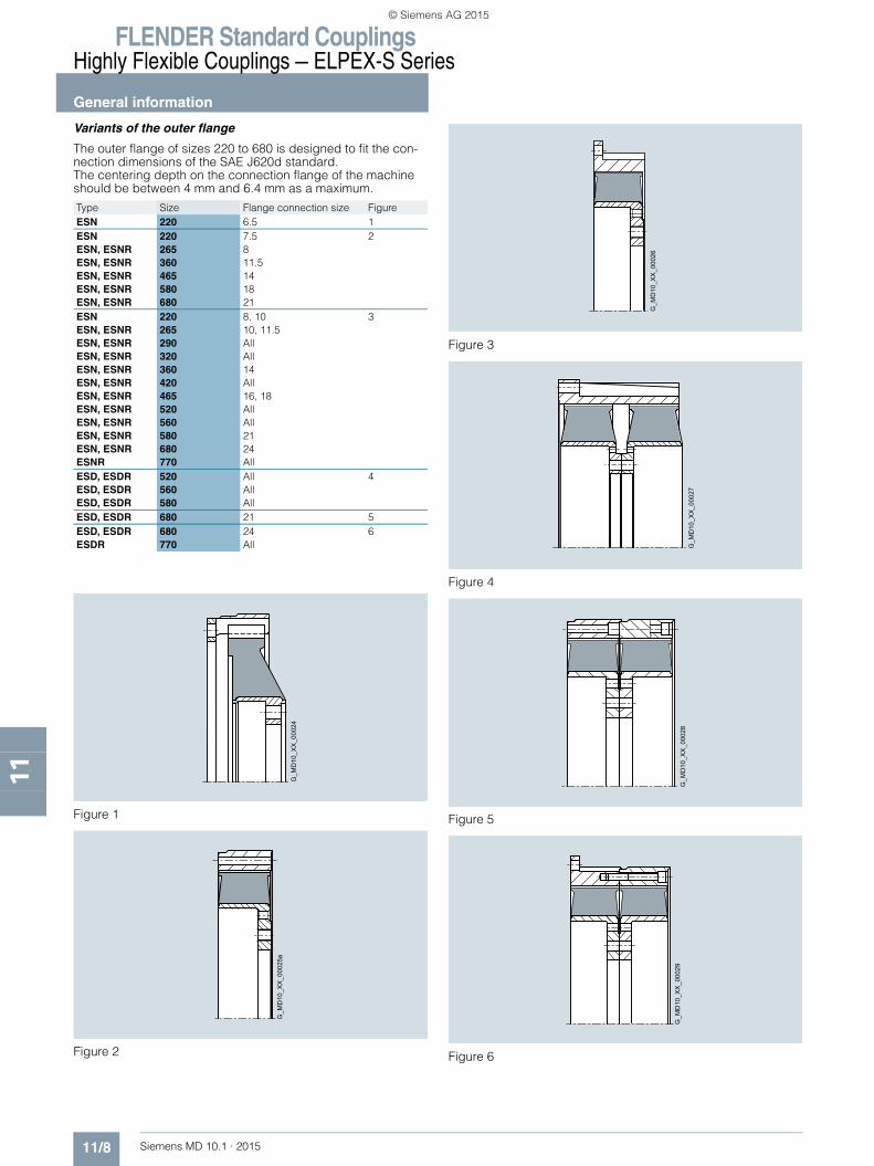
Variants of the outer flange
The outer flange of sizes 220 to 680 is designed to fit the con-nection dimensions of the SAE J620d standard. The centering depth on the connection flange of the machine should be between 4 mm and 6.4 mm as a maximum.
Figure 1
Figure 2
Figure 3
Figure 4
Figure 5
Figure 6
Type Size Flange connection size FigureESN 220 6.5 1ESNESN, ESNRESN, ESNRESN, ESNRESN, ESNRESN, ESNR
220265360465580680
7.5811.5141821
2
ESNESN, ESNRESN, ESNRESN, ESNRESN, ESNRESN, ESNRESN, ESNRESN, ESNRESN, ESNRESN, ESNRESN, ESNRESNR
220265290320360420465520560580680770
8, 1010, 11.5AllAll14All16, 18AllAll2124All
3
ESD, ESDRESD, ESDRESD, ESDR
520560580
AllAllAll
4
ESD, ESDR 680 21 5ESD, ESDRESDR
680770
24All
6
G_M
D10
_XX
_000
24
G_M
D10
_XX
_000
25a
G_M
D10
_XX
_000
26
G_M
D10
_XX
_000
27G
_MD
10_X
X_0
0028
G_M
D10
_XX
_000
29
MD10-1_2014_EN.book Seite 8 Freitag, 31. Juli 2015 6:11 18
© Siemens AG 2015

FLENDER Standard CouplingsHighly Flexible Couplings — ELPEX-S Series
11/9Siemens MD 10.1 · 2015
Type ESN
11
■ Selection and ordering data
The rubber disk element cannot be dismounted until the machines have been moved.
Weight and mass moments of inertia apply to maximum bore diameters.Ordering example:ELPEX-S ESN coupling, size 520, WN rubber element, hub with bore ∅D2 = 150H7 mm, with keyway to DIN 6885 and set screw, outer flange to SAE J620d size 21.
Article No.: short version: 2LC0220-7AA09-1JA0 M1Wlong version: 2LC0220-7AB09-1JA0 M1W
A LG
short versionVariant G
_MD
10_E
N_0
0031
1J 2J
ZF x ØDFB
ØD
FAØ
DFK
ØD
2
ØD
AØ
ND
2
FBA LG
NL2S
Part 3 Part 5 Part 2
long versionVariant
G_MD10_EN_00030
Size Dimensions in mm Mass moment of inertia
Article No.with order codes M.. for bore diameter ∅D2 and tolerances (article number without "-Z") – selection in catalog part 3
WeightFlange connection dimensions
D2Keyway DIN 6885
DA ND2 NL2 A LG A S LG SAE DFA DFK FB ZF DFB J1 J2 mshort version long version g7
max. Size kgm2 kgm2 kg220 60 222 98 54 – – 0 49 103 6.5 215.9 200.0 6 6 8.5 0.008 0.01 2LC0220-0A B 0 ■ - ■ AA0 5.8
237 40 94 7.5 241.3 222.3 33 8 8.5 0.011 2LC0220-0A B 0 ■ - ■ BA0 6.1222 40 94 8 263.5 244.5 8 6 10.5 0.011 2LC0220-0A B 0 ■ - ■ CA0 6.4222 40 94 10 314.3 295.3 8 8 10.5 0.017 2LC0220-0A B 0 ■ - ■ DA0 6.9
265 65 263 118 65 15 74 3 39 104 8 263.5 244.5 33 6 10.5 0.011 0.022 2LC0220-1A ■ 0 ■ - ■ CA0 6.610 314.3 295.3 10 8 0.017 2LC0220-1A ■ 0 ■ - ■ DA0 6.911.5 352.4 333.4 10 8 0.024 2LC0220-1A ■ 0 ■ - ■ EA0 7.2
290 65 290 118 70 18 58 6 36 106 10 314.3 295.3 16 8 10.5 0.026 0.026 2LC0220-2A ■ 0 ■ - ■ DA0 9.211.5 352.4 333.4 16 8 0.036 2LC0220-2A ■ 0 ■ - ■ EA0 10.5
320 80 318 140 87 15 96 2 70 157 11.5 352.4 333.4 16 8 10.5 0.062 0.061 2LC0220-3A ■ 0 ■ - ■ EA0 1914 466.7 438.2 16 8 13 0.18 2LC0220-3A ■ 0 ■ - ■ FA0 20.5
360 90 358 160 105 29 92 13 56 161 11.5 352.4 333.4 54 8 10.5 0.065 0.13 2LC0220-4A ■ 0 ■ - ■ EA0 24.514 466.7 438.2 15 8 13 0.18 2LC0220-4A ■ 0 ■ - ■ FA0 27.5
420 100 420 185 102 26 92 10 72 174 14 466.7 438.2 18 8 13 0.22 0.32 2LC0220-5A ■ 0 ■ - ■ FA0 3616 517.5 489.0 18 8 13 0.32 2LC0220-5A ■ 0 ■ - ■ GA0 3818 571.5 542.9 18 6 17 0.47 2LC0220-5A ■ 0 ■ - ■ HA0 40
465 120 465 222 125 33 92 2 39 164 14 466.7 438.2 85 8 13 0.31 0.58 2LC0220-6A ■ 0 ■ - ■ FA0 5616 517.5 489.0 27 8 13 0.41 2LC0220-6A ■ 0 ■ - ■ GA0 5718 571.5 542.9 18 6 17 0.52 2LC0220-6A ■ 0 ■ - ■ HA0 61
520 165 514 250 142 16 159 0 83 225 18 571.5 542.9 18 12 17 0.48 0.93 2LC0220-7A ■ 0 ■ - ■ HA0 5521 673.1 641.4 18 12 0.95 2LC0220-7A ■ 0 ■ - ■ JA0 60
560 200 560 320 140 30 130 2.5 83 223 18 571.5 542.9 35 12 17 0.85 1.2 2LC0220-8A ■ 0 ■ - ■ HA0 6921 673.1 641.4 20 12 1.8 2LC0220-8A ■ 0 ■ - ■ JA0 78
580 200 580 316 200 23 215 0 100 300 18 571.5 542.9 104 12 17 0.77 1.8 2LC0221-0A ■ 0 ■ - ■ HA0 10021 673.1 641.4 26 12 1.2 2LC0221-0A ■ 0 ■ - ■ JA0 105
680 220 682 380 210 24 232 0 102 312 21 673.1 641.4 85 12 17 4.1 5.3 2LC0221-1A ■ 0 ■ - ■ JA0 20524 733.4 692.2 20 12 21 5.3 2LC0221-1A ■ 0 ■ - ■ KA0 215
Variant • short version A• long version B
∅D2 • Without finished bore – Without order codes 1• With finished bore – With order codes for diameter and tolerance (article number without "-Z") 9
Rubber element • WN 1• NN 2• SN 3• NX 4
MD10-1_2014_EN.book Seite 9 Freitag, 31. Juli 2015 6:11 18
© Siemens AG 2015
FLENDER Standard CouplingsHighly Flexible Couplings — ELPEX-S Series
Type ESD
11/10 Siemens MD 10.1 · 2015
11
■ Selection and ordering data
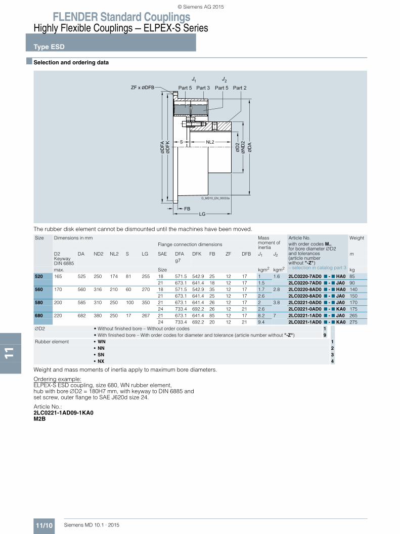
The rubber disk element cannot be dismounted until the machines have been moved.
Weight and mass moments of inertia apply to maximum bore diameters.
Ordering example:ELPEX-S ESD coupling, size 680, WN rubber element, hub with bore ∅D2 = 180H7 mm, with keyway to DIN 6885 and set screw, outer flange to SAE J620d size 24.
Article No.: 2LC0221-1AD09-1KA0 M2B
Size Dimensions in mm Mass moment of inertia
Article No.with order codes M.. for bore diameter ∅D2 and tolerances (article number without "-Z")– selection in catalog part 3
WeightFlange connection dimensions
D2Keyway DIN 6885
DA ND2 NL2 S LG SAE DFA DFK FB ZF DFB J1 J2 mg7
max. Size kgm2 kgm2 kg520 165 525 250 174 81 255 18 571.5 542.9 25 12 17 1 1.6 2LC0220-7AD0 ■ - ■ HA0 85
21 673.1 641.4 18 12 17 1.5 2LC0220-7AD0 ■ - ■ JA0 90560 170 560 316 210 60 270 18 571.5 542.9 35 12 17 1.7 2.8 2LC0220-8AD0 ■ - ■ HA0 140
21 673.1 641.4 25 12 17 2.6 2LC0220-8AD0 ■ - ■ JA0 150580 200 585 310 250 100 350 21 673.1 641.4 26 12 17 2 3.8 2LC0221-0AD0 ■ - ■ JA0 170
24 733.4 692.2 26 12 21 2.6 2LC0221-0AD0 ■ - ■ KA0 175680 220 682 380 250 17 267 21 673.1 641.4 85 12 17 8.2 7 2LC0221-1AD0 ■ - ■ JA0 265
24 733.4 692.2 20 12 21 9.4 2LC0221-1AD0 ■ - ■ KA0 275∅D2 • Without finished bore – Without order codes 1
• With finished bore – With order codes for diameter and tolerance (article number without "-Z") 9Rubber element • WN 1
• NN 2• SN 3• NX 4
ZF x ØDFB
ØD
2
ØD
A
ØD
FKØ
DFA
ØN
D2NL2S
LGFB
1J 2J
G_MD10_EN_00033a
Part 5 Part 3 Part 5 Part 2
MD10-1_2014_EN.book Seite 10 Freitag, 31. Juli 2015 6:11 18
© Siemens AG 2015

FLENDER Standard CouplingsHighly Flexible Couplings — ELPEX-S Series
11/11Siemens MD 10.1 · 2015
Type ESNR
11
■ Selection and ordering data
Weight and mass moments of inertia apply to maximum bore diameters.P, Q = required space for radial dismounting of the rubber disk element
Ordering example:ELPEX-S ESNR coupling, size 320, WN rubber element, hub with bore ∅D2 = 50H7 mm, with keyway to DIN 6885 and set screw, outer flange to SAE J620d size 14.
Article No.: 2LC0220-3AC09-1FA0 M1C
1J 2J
ZF x ØDFB
ØD
2
ØD
AØ
ND
2S NL2
A
P
LGFB
ØD
FA
ØD
FKØ
Q
Part 3 Part 5 Part 2
G_MD10_EN_00032
Size Dimensions in mm Mass moment of inertia
Article No.with order codes M.. for bore diameter ∅D2 and tolerances (article number without "-Z")– selection in catalog part 3
WeightFlange connection dimensions
D2Keyway DIN 6885
DA ND2 NL2 S A P Q LG SAE DFA DFK FB ZF DFB J1 J2 mg7
max. Size kgm2 kgm2 kg265 50 263 78 65 42 – 10 225 107 8 263.5 244.5 33 6 10.5 0.011 0.022 2LC0220-1AC0 ■ - ■ CA0 5.0
10 314.3 295.3 10 8 0.017 2LC0220-1AC0 ■ - ■ DA0 5.311.5 352.4 333.4 10 8 0.024 2LC0220-1AC0 ■ - ■ EA0 5.6
290 50 290 78 65 59 2 15 276 124 10 314.3 295.3 16 8 10.5 0.026 0.026 2LC0220-2AC0 ■ - ■ DA0 8.111.5 352.4 333.4 16 8 0.036 2LC0220-2AC0 ■ - ■ EA0 8.4
320 65 318 98 87 74 0 20 310 161 11.5 352.4 333.4 16 8 10.5 0.062 0.061 2LC0220-3AC0 ■ - ■ EA0 13.514 466.7 438.2 16 8 13 0.18 2LC0220-3AC0 ■ - ■ FA0 16
360 85 358 123 88 77 9 28 314 165 11.5 352.4 333.4 54 8 10.5 0.065 0.13 2LC0220-4AC0 ■ - ■ EA0 2014 466.7 438.2 15 8 13 0.18 2LC0220-4AC0 ■ - ■ FA0 23
420 100 420 155 85 93 6 28 409 178 14 466.7 438.2 18 8 13 0.22 0.32 2LC0220-5AC0 ■ - ■ FA0 3116 517.5 489.0 18 8 13 0.32 2LC0220-5AC0 ■ - ■ GA0 3218 571.5 542.9 18 6 17 0.47 2LC0220-5AC0 ■ - ■ HA0 35
465 130 465 190 119 88 – 15 409 207 14 466.7 438.2 85 8 13 0.31 0.58 2LC0220-6AC0 ■ - ■ FA0 4116 517.5 489.0 27 8 13 0.41 2LC0220-6AC0 ■ - ■ GA0 4218 571.5 542.9 18 6 17 0.52 2LC0220-6AC0 ■ - ■ HA0 45
520 150 514 227 162 85 – 10 498 247 18 571.5 542.9 18 12 17 0.48 0.93 2LC0220-7AC0 ■ - ■ HA0 5921 673.1 641.4 18 12 0.95 2LC0220-7AC0 ■ - ■ JA0 64
560 150 560 240 180 99 – 10 498 279 18 571.5 542.9 35 12 17 0.85 1.2 2LC0220-8AC0 ■ - ■ HA0 7521 673.1 641.4 20 12 1.8 2LC0220-8AC0 ■ - ■ JA0 85
580 160 580 240 200 102 – 10 498 302 18 571.5 542.9 104 12 17 0.77 1.8 2LC0221-0AC0 ■ - ■ HA0 8021 673.1 641.4 26 12 1.2 2LC0221-0AC0 ■ - ■ JA0 84
680 200 682 300 210 102 – 10 584 312 21 673.1 641.4 85 12 17 4.1 5.3 2LC0221-1AC0 ■ - ■ JA0 15524 733.4 692.2 20 12 21 5.3 2LC0221-1AC0 ■ - ■ KA0 165
770 260 780 390 255 134 – 10 750 389 – 860.0 820.0 26 32 21 10.7 12 2LC0221-2AC0 ■ - ■ LA0 330– 920.0 880.0 27 32 21 15.4 2LC0221-2AC0 ■ - ■ MA0 350– 995.0 950.0 27 32 21 20.5 2LC0221-2AC0 ■ - ■ NA0 375
∅D2 • Without finished bore – Without order codes 1• With finished bore – With order codes for diameter and tolerance (article number without "-Z") 9
Rubber element • WN 1• NN 2• SN 3• NX 4
MD10-1_2014_EN.book Seite 11 Freitag, 31. Juli 2015 6:11 18
© Siemens AG 2015
FLENDER Standard CouplingsHighly Flexible Couplings — ELPEX-S Series
Type ESDR
11/12 Siemens MD 10.1 · 2015
11
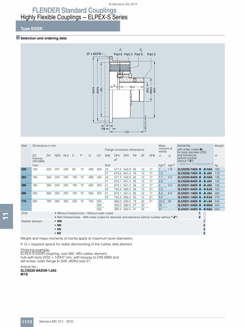
■ Selection and ordering data
Weight and mass moments of inertia apply to maximum bore diameters.
P, Q = required space for radial dismounting of the rubber disk element
Ordering example:ELPEX-S ESDR coupling, size 560, WN rubber element, hub with bore ∅D2 = 120H7 mm, with keyway to DIN 6885 and set screw, outer flange to SAE J620d size 21.
Article No.: 2LC0220-8AE09-1JA0M1S
ZF x ØDFB
ØD
2
ØD
A
ØQ
ØD
FK
ØD
FA
ØN
D2
S NL2
P
LGFB
1J 2JPart 6 Part 3 Part 5 Part 2
G_M
D10
_EN
_000
34Size Dimensions in mm Mass
moment of inertia
Article No.with order codes M.. for bore diameter ∅D2 and tolerances (article number without "-Z")– selection in catalog part 3
WeightFlange connection dimensions
D2Keyway DIN 6885
DA ND2 NL2 S P Q LG SAE DFA DFK FB ZF DFB J1 J2 mg7
max. Size kgm2 kgm2 kg520 150 525 227 226 83 10 498 309 18 571.5 542.9 25 12 17 1 1.8 2LC0220-7AE0 ■ - ■ HA0 105
21 673.5 641.4 18 12 17 1.5 2LC0220-7AE0 ■ - ■ JA0 110560 160 560 240 240 100 10 498 340 18 571.5 542.9 35 12 17 1.7 2.5 2LC0220-8AE0 ■ - ■ HA0 135
21 673.1 641.4 25 12 17 2.6 2LC0220-8AE0 ■ - ■ JA0 140580 160 585 240 250 100 10 560 350 21 673.1 641.4 26 12 17 2 3.2 2LC0221-0AE0 ■ - ■ JA0 145
24 733.4 692.2 26 12 21 2.6 2LC0221-0AE0 ■ - ■ KA0 150680 200 682 300 250 102 10 584 352 21 673.1 641.4 85 12 17 8.2 6.5 2LC0221-1AE0 ■ - ■ JA0 260
24 733.4 692.2 20 12 21 9.4 2LC0221-1AE0 ■ - ■ KA0 270770 260 780 390 300 200 10 750 500 860.0 820.0 19 32 21 22.3 20 2LC0221-2AE0 ■ - ■ LA0 540
500 920.0 880.0 27 32 26 2LC0221-2AE0 ■ - ■ MA0 555500 995.0 950.0 27 32 31 2LC0221-2AE0 ■ - ■ NA0 600
∅D2 • Without finished bore – Without order codes 1• With finished bore – With order codes for diameter and tolerance (article number without "-Z") 9
Rubber element • WN 1• NN 2• SN 3• NX 4
MD10-1_2014_EN.book Seite 12 Freitag, 31. Juli 2015 6:11 18
© Siemens AG 2015

FLENDER Standard CouplingsHighly Flexible Couplings — ELPEX-S Series
11/13Siemens MD 10.1 · 2015
Types ESNW and ESDW
11
■ Selection and ordering data
Type ESNW Type ESDW
Weight and mass moments of inertia apply to maximum bore diameters.
Ordering example:ELPEX-S ESNW coupling, size 520, WN rubber element, hub with bore ∅D1 = 140H7 mm, with keyway to DIN 6885 and set screw, bore ∅D2 = 120H7 mm, with keyway to DIN 6885 and set screw.
Article No.: 2LC0220-7AG99-1AA0L1V+M1S
1J 2J
ØD
2
ØD
AØ
ND
2
ØD
1Ø
ND
1
L3 L4
SNL1 NL2
LG
Part 3Part 1 Part 5 Part 2
G_M
D10
_EN
_000
36
ØD
1
ØD
2
ØD
A
ØN
D1
ØN
D2S NL2NL1
L3 L4
LG
1J 2JPart 6 Part 3 Part 5 Part 2Part 1
G_M
D10
_EN
_000
37
Size Dimensions in mm Mass moment of inertia
Article No.with order codes M.. for bore diameter ∅D2 and tolerances (article number without "-Z")– selection in catalog part 3
Weight
D1/D2Keyway DIN 6885
DA ND1/ND2 NL1/NL2 L3 L4 S LG J1 J2 m
max. kgm2 kgm2 kgType ESNW265 50 275 78 65 62 66 68 198 0.11 0.017 2LC0220-1AG ■ ■ - ■ AA0 15290 50 325 78 65 62 68 89 219 0.21 0.028 2LC0220-2AG ■ ■ - ■ AA0 22320 65 365 98 87 84 92 105 279 0.37 0.042 2LC0220-3AG ■ ■ - ■ AA0 32360 85 365 123 88 85 96 123 299 0.45 0.11 2LC0220-4AG ■ ■ - ■ AA0 43420 100 480 155 85 82 94 134 304 1.5 0.3 2LC0220-5AG ■ ■ - ■ AA0 75465 130 480 190 119 116 119 125 363 1.6 0.54 2LC0220-6AG ■ ■ - ■ AA0 89520 150 585 227 162 159 161 123 447 4 0.94 2LC0220-7AG ■ ■ - ■ AA0 155560 150 585 240 180 174 174 132 492 4.1 1.2 2LC0220-8AG ■ ■ - ■ AA0 160580 160 685 240 200 195 198 145 545 5.5 1.6 2LC0221-0AG ■ ■ - ■ AA0 185680 200 685 300 210 205 201 150 570 12 3.6 2LC0221-1AG ■ ■ - ■ AA0 315770 260 870 390 255 250 253 180 690 27.2 12 2LC0221-2AG ■ ■ - ■ AA0 500Type ESDW520 150 585 227 226 201 135 100 552 4.7 1.8 2LC0220-7AH ■ ■ - ■ AA0 215560 160 585 240 240 215 133 114 594 5.4 2.5 2LC0220-8AH ■ ■ - ■ AA0 250580 160 685 240 250 220 140 120 620 10.1 3.2 2LC0221-0AH ■ ■ - ■ AA0 300680 200 685 300 250 218 134 125 625 14.5 6.5 2LC0221-1AH ■ ■ - ■ AA0 440770 260 870 390 300 265 238 220 820 40 20 2LC0221-2AH ■ ■ - ■ AA0 720∅D1 • Without finished bore – Without order codes 1 1
• With finished bore – With order codes for diameter and tolerance (article number without "-Z") 9 9∅D2 • Without finished bore – Without order codes 1
• With finished bore – With order codes for diameter and tolerance (article number without "-Z") 9Rubber element • WN 1
• NN 2• SN 3• NX 4
MD10-1_2014_EN.book Seite 13 Freitag, 31. Juli 2015 6:11 18
© Siemens AG 2015
FLENDER Standard CouplingsHighly Flexible Couplings — ELPEX-S Series
Type EST
11/14 Siemens MD 10.1 · 2015
11
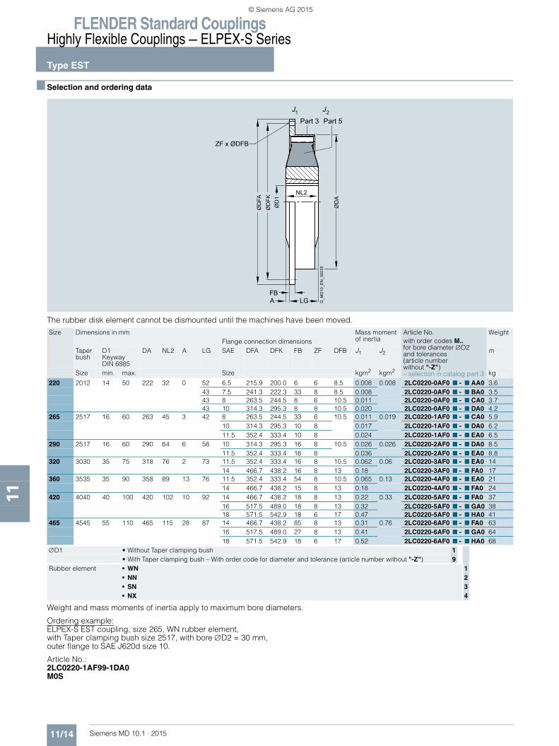
■ Selection and ordering data
The rubber disk element cannot be dismounted until the machines have been moved.
Weight and mass moments of inertia apply to maximum bore diameters.
Ordering example:ELPEX-S EST coupling, size 265, WN rubber element, with Taper clamping bush size 2517, with bore ∅D2 = 30 mm, outer flange to SAE J620d size 10.
Article No.: 2LC0220-1AF99-1DA0M0S
Size Dimensions in mm Mass moment of inertia
Article No.with order codes M.. for bore diameter ∅D2 and tolerances (article number without "-Z")– selection in catalog part 3
WeightFlange connection dimensions
Taper bush
D1Keyway DIN 6885
DA NL2 A LG SAE DFA DFK FB ZF DFB J1 J2 m
Size min. max. Size kgm2 kgm2 kg
220 2012 14 50 222 32 0 52 6.5 215.9 200.0 6 6 8.5 0.008 0.008 2LC0220-0AF0 ■ - ■ AA0 3.643 7.5 241.3 222.3 33 8 8.5 0.008 2LC0220-0AF0 ■ - ■ BA0 3.543 8 263.5 244.5 8 6 10.5 0.011 2LC0220-0AF0 ■ - ■ CA0 3.743 10 314.3 295.3 8 8 10.5 0.020 2LC0220-0AF0 ■ - ■ DA0 4.2
265 2517 16 60 263 45 3 42 8 263.5 244.5 33 6 10.5 0.011 0.019 2LC0220-1AF0 ■ - ■ CA0 5.910 314.3 295.3 10 8 0.017 2LC0220-1AF0 ■ - ■ DA0 6.211.5 352.4 333.4 10 8 0.024 2LC0220-1AF0 ■ - ■ EA0 6.5
290 2517 16 60 290 64 6 58 10 314.3 295.3 16 8 10.5 0.026 0.026 2LC0220-2AF0 ■ - ■ DA0 8.511.5 352.4 333.4 16 8 0.036 2LC0220-2AF0 ■ - ■ EA0 8.8
320 3030 35 75 318 76 2 73 11.5 352.4 333.4 16 8 10.5 0.062 0.06 2LC0220-3AF0 ■ - ■ EA0 1414 466.7 438.2 16 8 13 0.18 2LC0220-3AF0 ■ - ■ FA0 17
360 3535 35 90 358 89 13 76 11.5 352.4 333.4 54 8 10.5 0.065 0.13 2LC0220-4AF0 ■ - ■ EA0 2114 466.7 438.2 15 8 13 0.18 2LC0220-4AF0 ■ - ■ FA0 24
420 4040 40 100 420 102 10 92 14 466.7 438.2 18 8 13 0.22 0.33 2LC0220-5AF0 ■ - ■ FA0 3716 517.5 489.0 18 8 13 0.32 2LC0220-5AF0 ■ - ■ GA0 3818 571.5 542.9 18 6 17 0.47 2LC0220-5AF0 ■ - ■ HA0 41
465 4545 55 110 465 115 28 87 14 466.7 438.2 85 8 13 0.31 0.76 2LC0220-6AF0 ■ - ■ FA0 6316 517.5 489.0 27 8 13 0.41 2LC0220-6AF0 ■ - ■ GA0 6418 571.5 542.9 18 6 17 0.52 2LC0220-6AF0 ■ - ■ HA0 68
∅D1 • Without Taper clamping bush 1• With Taper clamping bush – With order code for diameter and tolerance (article number without "-Z") 9
Rubber element • WN 1• NN 2• SN 3• NX 4
1J 2J
ZF x ØDFB
ØD
1
ØD
A
NL2
FBA LG
ØD
FAØ
DFK
Part 3 Part 5
G_M
D10
_EN
_000
35
MD10-1_2014_EN.book Seite 14 Freitag, 31. Juli 2015 6:11 18
© Siemens AG 2015

FLENDER Standard CouplingsHighly Flexible Couplings — ELPEX-S Series
11/15Siemens MD 10.1 · 2015
Spare and wear parts
11
■ Selection and ordering data
Rubber disk elements
The rubber disk elements of the ELPEX-S coupling are wear parts. The service life depends on the operating conditions.
Ordering examples:WN rubber element for ELPEX-S EST 265 coupling, including taper bush 2517 with bore ∅D1 = 24 mm, keyway to DIN 6885.
Article No.:2LC0220-1XL90-1AA0L0P
WN rubber element for ELPEX-S EST 265 coupling without Taper clamping bush.
Article No.:2LC0220-1XL10-1AA0
Size Article No. set of rubber disk elements for a couplingTypeEST ESN ESNR, ESNW ESD ESDR, ESDW
220 2LC0220-0XL ■ 0- ■ AA0 2LC0220-0XJ00- ■ AA0265 2LC0220-1XL ■ 0- ■ AA0 2LC0220-1XJ00- ■ AA0 2LC0220-1XM00- ■ AA0290 2LC0220-2XL ■ 0- ■ AA0 2LC0220-2XJ00- ■ AA0 2LC0220-2XM00- ■ AA0320 2LC0220-3XL ■ 0- ■ AA0 2LC0220-3XJ00- ■ AA0 2LC0220-3XM00- ■ AA0360 2LC0220-4XL ■ 0- ■ AA0 2LC0220-4XJ00- ■ AA0 2LC0220-4XM00- ■ AA0420 2LC0220-5XL ■ 0- ■ AA0 2LC0220-5XJ00- ■ AA0 2LC0220-5XM00- ■ AA0465 2LC0220-6XL ■ 0- ■ AA0 2LC0220-6XJ00- ■ AA0 2LC0220-6XM00- ■ AA0520 2LC0220-7XJ00- ■ AA0 2LC0220-7XM00- ■ AA0 2LC0220-7XK00- ■ AA0 2LC0220-7XN00- ■ AA0560 2LC0220-8XJ00- ■ AA0 2LC0220-8XM00- ■ AA0 2LC0220-8XK00- ■ AA0 2LC0220-8XN00- ■ AA0580 2LC0221-0XJ00- ■ AA0 2LC0221-0XM00- ■ AA0 2LC0221-0XK00- ■ AA0 2LC0221-0XN00- ■ AA0680 2LC0221-1XJ00- ■ AA0 2LC0221-1XM00- ■ AA0 2LC0221-1XK00- ■ AA0 2LC0221-1XN00- ■ AA0770 2LC0221-2XM00- ■ AA0 2LC0221-2XN00- ■ AA0Without Taper clamping bush 1With Taper clamping bush 9Rubber element • WN 1 1 1 1 1
• NN 2 2 2 2 2• SN 3 3 3 3 3• NX 4 4 4 4 4
MD10-1_2014_EN.book Seite 15 Freitag, 31. Juli 2015 6:11 18
© Siemens AG 2015

FLENDER Standard CouplingsHighly Flexible Couplings — ELPEX-S Series
Notes
11/16 Siemens MD 10.1 · 2015
11
MD10-1_2014_EN.book Seite 16 Freitag, 31. Juli 2015 6:11 18
© Siemens AG 2015