highway laboratory introductionfac.ksu.edu.sa/sites/default/files/lab_note_1... · 2018-02-12 ·...
TRANSCRIPT

1
Eng. Ibrahim Almohanna, 2018 CE 432: Highway Laboratory. Note #1
http://fac.ksu.edu.sa/ialmohanna/
Highway Laboratory
Introduction
• Laboratory testing of materials used for highway construction and maintenance is an
essential part of highway engineering.
• The course includes testing procedures of soil, aggregates, asphalts and mix design
procedures.
• At the beginning of the class, there will be a lecture on the experiment and thereafter the
test is conducted.
• All students are required to collect the data and submit the data sheet for approval by the
instructor.
• Necessary precautions should always be taken to avoid any possible hazards.
• One week after the completion of the test, each student should submit a written report.
The report should consist of the following sections:
o Cover Page
o Aim, Apparatus and Procedures.
o Experimental Data and Results.
o Discussion and Conclusion.

2
Eng. Ibrahim Almohanna, 2018 CE 432: Highway Laboratory. Note #1
http://fac.ksu.edu.sa/ialmohanna/
Flexible Pavement
Figure 1: Cross section in a paved highway.
• Seal Coat:
Seal coat is a thin surface treatment used to water-proof the surface or repair defects and to provide
skid resistance.
• Tack Coat:
Tack coat is a very light application of asphalt, usually asphalt emulsion diluted with water. It
provides proper bonding between two layer of binder course and must be thin.
• Prime Coat:
Prime coat is an application of low viscous cutback bitumen to an absorbent surface like granular
bases on which binder layer is placed. It provides bonding between two layers. Unlike tack coat,
prime coat penetrates the layer below, plugs the voids, and forms a water tight surface.
• Surface course
Surface course is the layer directly in contact with traffic loads and generally contains superior
quality materials. They are usually constructed with dense graded asphalt concrete(AC).
3
Eng. Ibrahim Almohanna, 2018 CE 432: Highway Laboratory. Note #1
http://fac.ksu.edu.sa/ialmohanna/
• Binder course and leveling course
This layer provides the bulk of the asphalt concrete structure. Its chief purpose is to distribute
load to the base course. It consists of aggregates having less asphalt.
• Base course
The base course is the layer of material immediately beneath the surface of binder course and it
provides additional load distribution. It may be composed of crushed stone, crushed slag, and
other untreated or stabilized materials.
• Sub-Base course
The sub-base course is the layer of material beneath the base course. A sub-base course is not
always needed or used. For example, a pavement constructed over a high quality, stiff sub-grade
may not need the additional features offered by a sub-base course. In such situations, sub-base
course may not be provided.
• Sub-grade
The top soil or sub-grade is a layer of natural soil prepared to receive the stresses from the layers
above.
▪ Not all layers and coats are present in every pavement structure.
▪ Binder course and leveling course may be placed in one or lifts.
▪ Tack coats may be required between layers of asphalt concrete.
▪ Prime coat may be required between aggregate layer and asphalt concrete layer.

4
Eng. Ibrahim Almohanna, 2018 CE 432: Highway Laboratory. Note #1
http://fac.ksu.edu.sa/ialmohanna/
Load Distribution of Pavement Layers
Flexible-pavement design is based on the principle that the magnitude of stress induced by a wheel
load decreases with depth below the surface. Consequently, the stresses induced on a given
subgrade material can be decreased by increasing the thickness of the overlying layers (subbase,
base, and surface courses).
Figure 2 demonstrates that the magnitude of the stresses on the subgrade decreases as the flexible-
pavement structure is thickened. In the left diagram in Figure 2, the flexible-pavement structure is
thick, the load at the subgrade level is spread over a wide area, and the stresses on the subgrade
are low. In the right diagram the structure is thin, the load at the subgrade level is confined to a
much smaller area, and the stresses on the subgrade level are significantly higher.
The pattern of decreasing stresses with increasing depth is the basis of the conventional flexible-
pavement design in which subgrade materials of low-bearing capacity are covered with thick
flexible-pavement structures.
Figure 2: Distribution of pressures under single wheel loads
Purpose of material testing:
1. Suitability of materials.
2. Quality control and quality assurance.
3. Material characterization and development.

5
Eng. Ibrahim Almohanna, 2018 CE 432: Highway Laboratory. Note #1
http://fac.ksu.edu.sa/ialmohanna/
Highway Materials
1. Asphalt (bituminous materials)
a. Asphalt cement
• Asphalt cement is a dark brown to black, highly viscous, hydrocarbon.
• Produced from petroleum distillation residue.
• This distillation can occur naturally, resulting in asphalt lakes,
• Alternatively, it occur in a petroleum refinery using crude oil.
• Categorized as: semi solid and hot mix.
b. Cutback asphalt
• Cutback asphalt is a combination of asphalt cement and petroleum solvent.
• Like emulsions, cutbacks are used because their viscosity is lower than that of
neat asphalt.
• Can be used in low temperature applications.
• After a cutback is applied, the solvent evaporates away and only the asphalt
cement is left.
• Cutbacks are much less common today because the petroleum solvent is more
expensive than water and can be an environmental concern.
• Cutbacks are typically used as prime coats and tack coats.
• Categorized as: rapid curing, medium curing, and slow curing.
c. Emulsified asphalt
• Emulsions have lower viscosities than neat (plain) asphalt
• Can be used in low temperature applications.
• After an emulsion is applied, the water evaporates away and only the asphalt
cement is left.
• Categorized as: rapid setting, medium setting, and slow setting.
• Emulsions are often used as:
▪ Prime coats and tack coats. Figure 3.
▪ Fog seals. Slow setting. Figure 4.
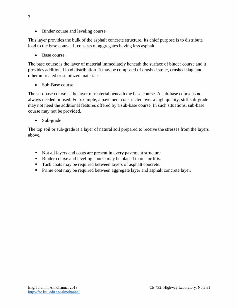
▪ Slurry seals. Used to fill existing pavement surface defects.
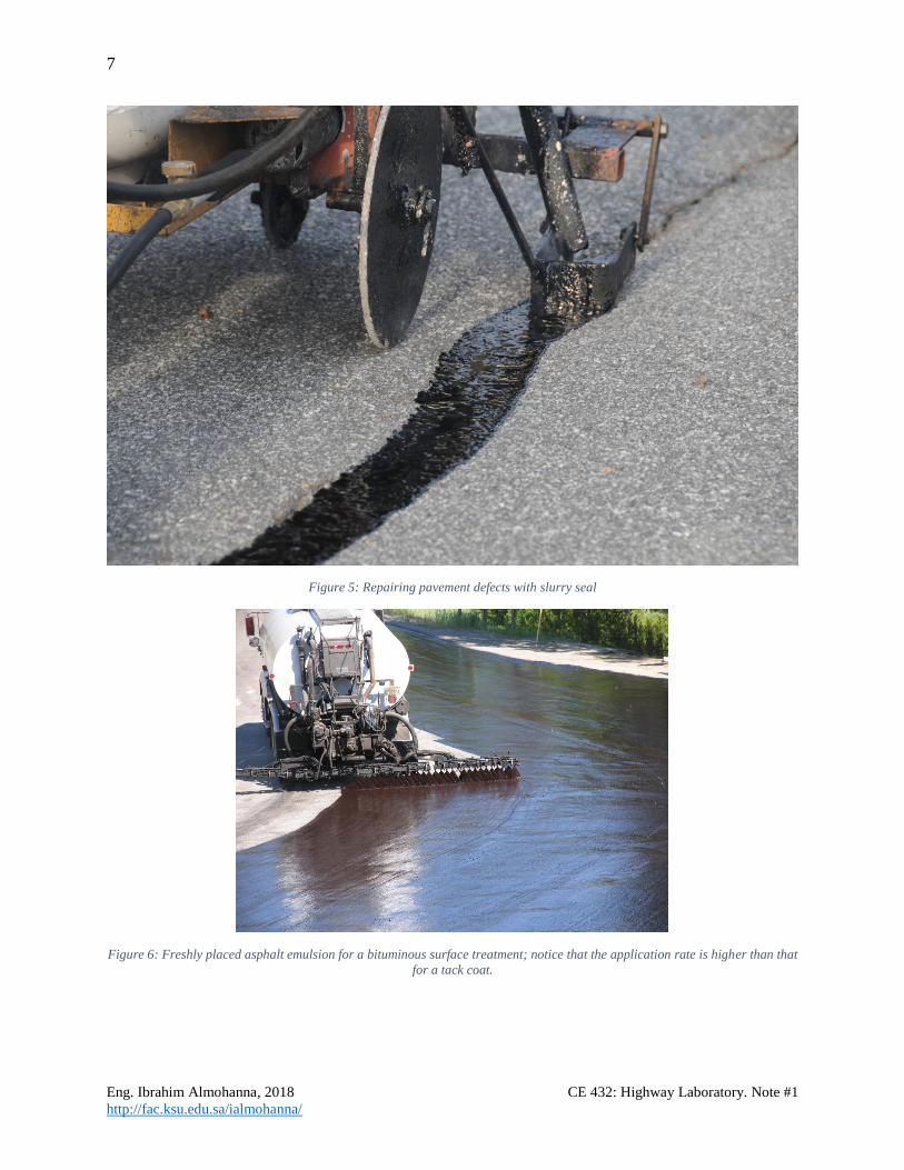
▪ Bituminous surface treatments (BST). Figure 6 and Figure 7.

6
Eng. Ibrahim Almohanna, 2018 CE 432: Highway Laboratory. Note #1
http://fac.ksu.edu.sa/ialmohanna/
Figure 3: Poor tack coat (shown in the left half of the photo) vs. a good tack coat (shown in the right half of the photo). Notice
the streaky coverage of the poor tack coat and the near complete coverage of the good tack coat.
Figure 4: fog seal.
7
Eng. Ibrahim Almohanna, 2018 CE 432: Highway Laboratory. Note #1
http://fac.ksu.edu.sa/ialmohanna/
Figure 5: Repairing pavement defects with slurry seal
Figure 6: Freshly placed asphalt emulsion for a bituminous surface treatment; notice that the application rate is higher than that
for a tack coat.

8
Eng. Ibrahim Almohanna, 2018 CE 432: Highway Laboratory. Note #1
http://fac.ksu.edu.sa/ialmohanna/
Figure 7: Chip seal rehabilitation over a BST.
Figure 8: Pavement smoothing

9
Eng. Ibrahim Almohanna, 2018 CE 432: Highway Laboratory. Note #1
http://fac.ksu.edu.sa/ialmohanna/
2. Aggregate and soil
▪ Approximately 92 % - 96%of the volume of asphalt concrete is aggregates. It comes from:
• Aggregates manufactured by crushing waste materials.
• Natural sand (<4.75mm) and gravel (>4.75mm).
• Aggregates crushed from selected natural rock.
i. Igneous Rocks (i.e. Basalt & granite).
ii. Metamorphic Rocks.
iii. Sedimentary Rocks (i.e. Limestone & sandstone).
▪ In hot mix asphalt (HMA), since aggregates are relied upon to provide stiffness and
strength by interlocking with one another, cubic angular-shaped particles with a rough
surface texture are best. Angular soil particle results in higher friction and round soil
particle results in lower friction.
▪ Flat or elongated particles tend to impede compaction or break during compaction and
thus, may decrease strength.
▪ Smooth-surfaced particles may be easier to coat with binder. However, in HMA asphalt
tends to bond more effectively with rough-surfaced particles, rough-surfaced particles
provide more area to which the asphalt can bond.
Figure 9: Angular and round particles
3. Additives:
a. Portland cement. b. Lime. c. Anti-striping.

10
Eng. Ibrahim Almohanna, 2018 CE 432: Highway Laboratory. Note #1
http://fac.ksu.edu.sa/ialmohanna/
Sampling Method
1. Methods of taking representative field samples:
• Sampling from a Flowing Aggregate Stream (Bins or Belt Discharge):
o At least three approximately equal increments.
o Selected at random.
o All the increments are mixed to form a field sample.
• Sampling from the conveyor belt:
o At least three approximately equal increments.
o Selected at random.
o Stop the conveyor belt.
o Insert two templates.
o Scoop all material between the templates.
o All the increments are mixed to form a field sample.
• Sampling from stockpiles or transportation units:
o At least three approximately equal increments.
o From the top third, at the mid-point, and at the bottom third.
o A board shoved vertically into the pile just above the sampling point aids in
preventing segregation.
o For fine aggregate, the outer layer should be removed.
o For fine aggregate, sampling tubes may be inserted into the pile at random
locations to extract a minimum of five increments.
o All the increments are mixed to form a field sample.
2. Methods of taking small samples out of field samples:
• Quartering.
• Splitting.

11
Eng. Ibrahim Almohanna, 2018 CE 432: Highway Laboratory. Note #1
http://fac.ksu.edu.sa/ialmohanna/
Sieve Analysis of Fine and Coarse Aggregates
• The size of aggregate influences the surface area and thus influence the amount of
bitumen required to coat the surface of aggregates.
• Particle size distribution is called grading (sieve analysis).
• Grading controls packing density and therefore improves strength. See Figure 10.
In a gradation and size analysis, a sample of dry aggregate is separated through a series of sieves
with progressively smaller openings. Once separated, the weight of particles retained on each sieve
is measured. Particle size distribution is then expressed as a percent retained by weight on each
sieve size. Results are usually expressed in tabular or graphical format. Graphical displays almost
always use the standard 0.45 power gradation graph.
• This method covers determination of the particle size distribution of coarse and fine
aggregates.
o Gradation Curve.
o Nominal Maximum Size.
o Maximum density line.
Gradation types include (See Figure 11):
1. Well graded (dense graded).
Typical gradations are near the 0.45 power curve but not right on it.
2. Poorly graded (uniform).
Refers to a gradation that contains most of the particles in a very narrow size range. All
the particles are the same size. The curve is steep and only occupies the narrow size range
specified.
3. Gap graded.
Refers to a gradation that contains only a small percentage of aggregate particles in the
mid-size range. The curve is flat in the mid-size range. Gap graded mixes can be prone to
segregation during placement.
4. Open graded
Refers to a gradation that contains only a small percentage of aggregate particles in the
small range. This results in more air voids because there are not enough small particles to
fill in the voids between the larger particles. The curve is near vertical in the mid-size
range, and flat and near-zero in the small-size range.

12
Eng. Ibrahim Almohanna, 2018 CE 432: Highway Laboratory. Note #1
http://fac.ksu.edu.sa/ialmohanna/
Figure 10: Effect of particle size and grading on packing density
Figure 11: Different gradations of aggregate
Figure 12: Gradation curve
14
3
2

13
Eng. Ibrahim Almohanna, 2018 CE 432: Highway Laboratory. Note #1
http://fac.ksu.edu.sa/ialmohanna/
Figure 13: Gradation uses
Aggregate Size
▪ Maximum aggregate size
The smallest sieve through which 100 percent of the aggregate sample particles pass.
It is “one sieve larger than the nominal maximum size”
▪ Nominal maximum size (NMS)
The largest sieve that retains some of the aggregate particles but generally not more than 10
percent by weight.
It is “one sieve size larger than the first sieve to retain more than 10 percent of the material”.
subbase coarsesurface coarse
base coarse