highways in residential and commercial · pdf filehighways in residential and commercial...
TRANSCRIPT
D e s i g n G u i d e
P a r t O n e
Highways in Residential and Commercial Estates
H i g h w a y s i n R e s i d e n t i a l E s t a t e s
D E V O NC O U N T Y C O U N C I L
E N V I R O N M E N T

JA N 96
HI G H W A Y S I N RE S I D E N T I A L ES T A T E S
PA G E 1
PART 1
HIGHWAYS INRESIDENTIAL ESTATES
CONTENTS
Section
1. Introduction
2. General Design Considerations
3. Detailed Characteristics of Residential Roads
4. Car Parking
5. Traffic Calming
6. Suggestions for Landscaping
7. Technical Details.

HI G H W A Y S I N RE S I D E N T I A L A N D CO M M E R C I A L ES T A T E S - DE S I G N GU I D E
PA G E 2JA N 96
SECTION 1
INTRODUCTION
This Part of the Design Guide sets out the philosophies and detailed guidance on the layoutof residential estates, based on the 2nd edition of Design Bulletin 32. The principal changeswhen compared with the 1989 Design Guide that have been introduced or furtheremphasised are listed in the box below.
HI G H W A Y S I N RE S I D E N T I A L ES T A T E S
PA G E 3 JA N 96
SUMMARY OF CHANGES COMPARED WITH 1989 GUIDE
• it encourages a flexible approach so that estates are attractive and safe
• it adopts the philosophy that roads and dwellings etc should be thought of as cohesiveelements; roads should not be considered separately from dwellings, community andrecreational facilities, but as an integrated whole at the earliest stage of planning newdevelopment
• it advocates a more “permeable” layout, where loop roads are preferred to culs de sac, andwith more than one access for anything but the smallest development; this should increasesafety for pedestrians and vehicles, and make the layout more convenient and economical;(the name of each type of road has been amended from the previous guide to take theemphasis away from the collector/cul de sac philosophy)
• the maximum design speed is 32 kph (20 mph) - it being likely that a 20 mph restrictionzone will be sought for the whole of the estate
• traffic calming is required for all residential roads, and needs to be considered at an earlystage, rather than introducing it as an add-on extra
• suggestions are given on how gateways can assist in calming traffic at the entrance to adevelopment, and where calming features can be introduced, including how buildings orlandscaping can be used to block forward vistas
• it continues to advocate shared surface roads, which may be in the form of loops as well asculs de sac
• a fresh look has been given to housing courts, so that the maximum amount of space is keptin private ownership and hard surfaces do not predominate
• it illustrates how car parking provision should be conveniently located where the residentwants to park
• it says that small developments in villages and small town centres will merit specialconsideration over design standards and materials
• it stresses the importance of landscaping in integrating the highway into the overall layout,and how it should be considered at the outset, for instance by
retaining existing features, and how they can be part of a traffic calmingfeature, and choosing materials for surfacing and other detailing that emphasise asense of local distinctiveness

JA N 96
HI G H W A Y S I N RE S I D E N T I A L A N D CO M M E R C I A L ES T A T E S - DE S I G N GU I D E
PA G E 4PA G E 4
The Planning Framework in which proposals are considered and how adoption is achievedare dealt with in Part 3 of the Guide.
Developers and their agents are specifically requested to note the advantages in certaininstances of a design brief as set out in Section 2.2. Early discussion on the production of adesign brief will assist the rapid approval of the estate layout.

SECTION 2
THE GENERAL DESIGN CONSIDERATIONS -
ROADS AND FOOTPATHS
2.1 MAIN OBJECTIVES FOR LAYOUT AND DESIGN
2.1.1 The aim of this Guide is to show how the design and construction of estateroads and footpaths can be safe and convenient for residents, whilst at thesame time ensuring adequate accessibility. Furthermore, a flexibleapproach is encouraged so that estates are attractive, unique, secure andenvironmentally friendly, without making travel or servicing difficult.
HI G H W A Y S I N RE S I D E N T I A L ES T A T E S
PA G E 5 JA N 96
(a) to define a residential road system that minimises the danger andnuisance from vehicular traffic and limits vehicle speeds in thevicinity of homes
(b) to provide an environment that gives the feeling of security to theresidents and that will reduce the risk of crime
(c) to allow adequate accessibility for residents, service and emergencyvehicles but at the same time discouraging the use of residentialroads by traffic unconnected with the development
(d) to provide safe, attractive and convenient routes for pedestrians andcyclists both within the local area and to local community facilities
(e) to ensure that the new development can be adequately served bypublic transport
(f) to encourage adequate and convenient car parking provision withinthe vicinity of the dwelling in order to reduce the dangers anddifficulties arising from indiscriminate on-street car parking, andthe risk of crime
(g) to enable the efficient provision of public utilities and otherservices
(h) to ensure the construction of high quality roads, cycleways andfootpaths which can be adopted and efficiently maintained by theHighway Authority
(i) to encourage high quality designs for road and footpath layoutwhich incorporate landscaping to enhance the visual character ofresidential areas
(j) to suggest how roads and footways within new residentialdevelopments, especially in environmentally sensitive areas, areappropriate to the character of that area in terms of scale,appearance the and use of materials.
The Objectives
of the Guide
2.1.2 Thus, road and footpath design for residential areas should aim to keepvehicle speeds to a minimum, encourage drivers to respect the residentialarea, provide safe and convenient routes for cyclists and pedestrianswhilst at the same time providing short and convenient routes for driverswishing to reach particular properties. The layout should be intrinsicallyunattractive as a through route.

2.1.3 Every site is unique and these guidelines should enable designers toexploit any natural features to the fullest advantage. Resulting designsshould not only provide a diverse and interesting range of layouts for theresidential area itself but should also allow these to be successfullyincorporated within existing urban areas. The use of high qualitymaterials and local construction methods or materials to provideindividuality is encouraged.
2.2 THE DESIGN BRIEF
2.2.1 It would be very helpful if a Design Brief were drawn up for larger estates.This will enable the Local Planning Authority, the Highway Authority, thedeveloper and any other interested body to agree the requirements forthe development so that it is environmentally acceptable, is wellintegrated into the surrounding area both in vehicular, cycle andpedestrian links, and so that the highway layout functions adequately. Anagreed Design Brief, produced at an early stage, should speed up theapproval of the final layout.
2.2.2 Such a Design Brief is more appropriate for larger estates of more than50 houses, but also may be suitable for a smaller number of units inparticularly sensitive or difficult sites.
2.2.3 The Design Brief would undoubtedly cover matters related to the densityand type of building. It will probably also deal with the preferred layoutfor the residential roads and footpaths, the type of materials to be usedand the extent of any landscaping schemes. It may also highlight anyspecific design problems of how the development can be incorporatedinto the existing street scene.
2.2.4 The contents of the Brief would depend on the particular circumstancesof the development, but a check list for the highway aspects of a DesignBrief is given in Part 3 of this Design Guide, paragraph 1.3.8. Points toconsider including are:• the main points of access to the development for vehicles, pedestrians
and cyclists, and potential or existing routes to the various localfacilities such as health centres, shops etc.
• any off-site highway improvements that may be required • any particular problems associated with the existing highway network
in the vicinity and any measures required within the site to ensure thatextraneous traffic is excluded as far as practical
• whether any existing residential areas surrounding the site should beincorporated in a 20 mph zone; in this case additional traffic speedrestraint measures may be required on existing roads.
HI G H W A Y S I N RE S I D E N T I A L A N D CO M M E R C I A L ES T A T E S - DE S I G N GU I D E
PA G E 6JA N 96 PA G E 6
Why a Design
Brief is
Recommended
What a Design
Brief May
Contain
2.3 GENERAL DESIGN CONSIDERATIONS
2.3.1 The residential road system should be one of low speed and minimumtravel length to or from an individual dwelling; thus, accessibility will bemaintained but extraneous traffic discouraged. Section 3 of this Part ofthe Guide outlines the various types of roads that are suitable for aresidential area. Outside the residential area different considerationsapply, which are outside the scope of this Guide.
2.3.2 To design a road layout to accommodate any vehicle would lead tooverwide bends, junctions and turning heads. Therefore, the road layoutshould be designed to accommodate at least a refuse vehicle, with over-run areas for vehicles such as pantechnicons where necessary. On AccessRoads* it may well be that a refuse vehicle and a car would need to passeach other at any point, and on Transition Roads* a refuse vehicle mayneed to pass a midi-bus. However, each situation should be consideredon its own merits, and consultation with the Engineer is important at anearly stage. * see Section 3.1.
2.3.3 Safer residential roads result from the restraint of vehicle speeds, thusminimising the conflict between vehicles and other users. Whereverpossible, the design should ensure that vehicle speeds are below 20 mph;in many cases it is likely that the Highway Authority will seek a 20 mphspeed restriction zone for the whole area of the estate, and possiblyextending this zone into the surrounding residential areas. However, a20 mph zone can only be achieved where the design has ensured thatvehicle speeds are physically restrained to this level, as speeds are notrestrained by speed limits alone.
HI G H W A Y S I N RE S I D E N T I A L ES T A T E S
PA G E 7 JA N 96
The Residential
Road
Types of
Vehicles to be
Catered for
Speed Restraint
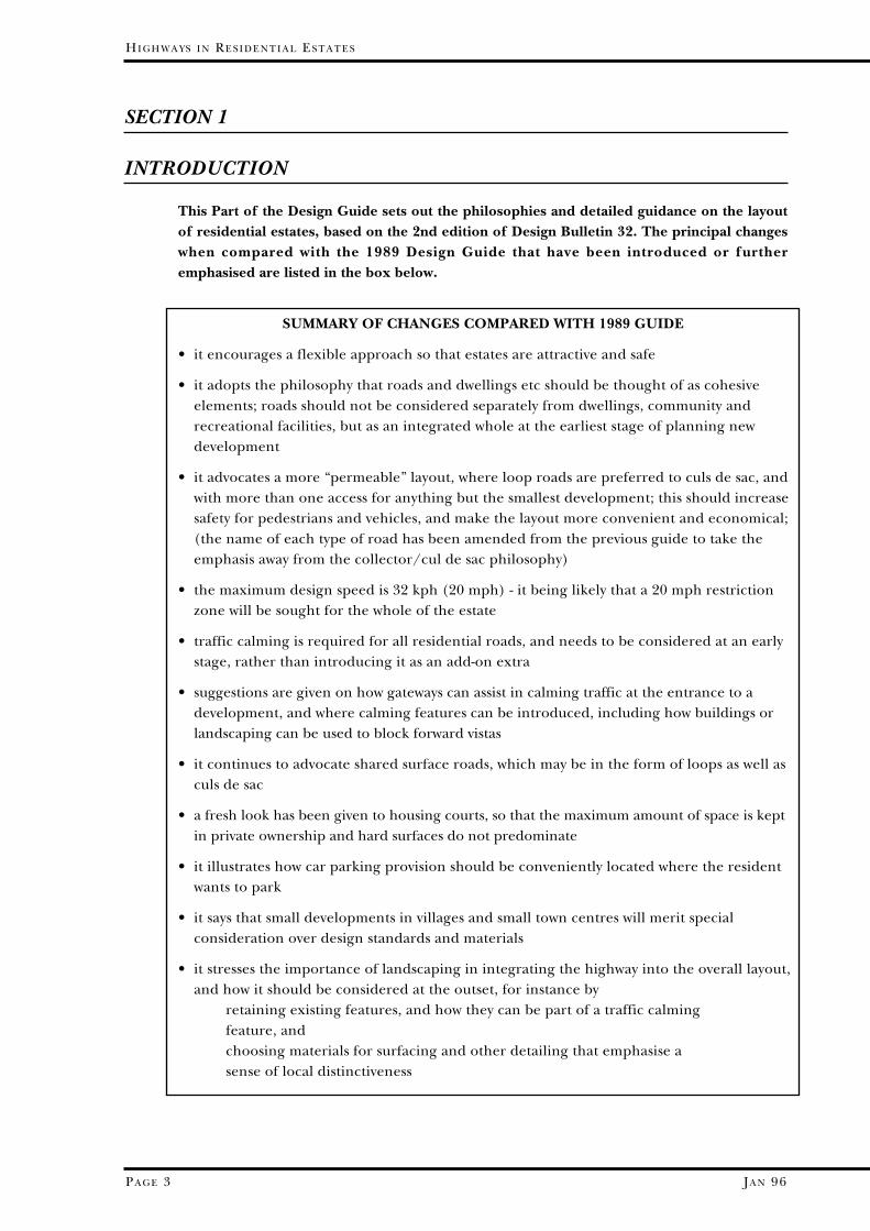
Gateways 2.3.4 The treatment of the entrance into the residential estate is important, sothat drivers are made aware that they are entering a slow speed area; thisfeature is known as a gateway. It should discourage speed and serve toalert drivers to expect higher volumes of pedestrians, cyclists, etc. Section5 of this Part of the Guide provides some concepts to consider in thedesign of gateways; for instance, materials or design features which arespecific to the particular type of estate could be included. Although it is
JA N 96
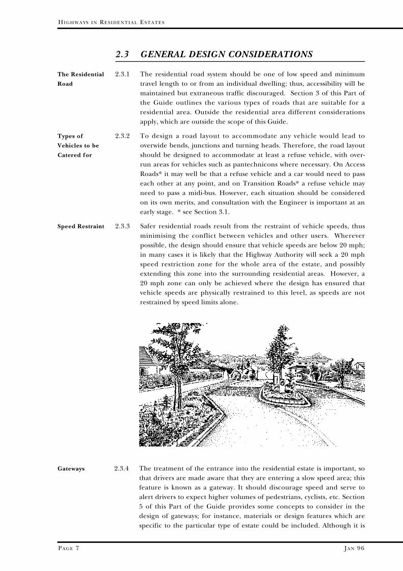
more difficult to apply this type of approach to smaller residentialdevelopment such as a single cul de sac, it is still important to changedriver attitude on entry to the residential area. Gateways should beincorporated into the design wherever vehicles leave the normal highwaynetwork.
2.3.5 Speed restraint within the development itself can be achieved byregularly spaced traffic calming measures, and Section 5 gives somedetails of these. Their frequency should be:-
Type R1 Residential Transition Road 100m spacingType R2 Access Road 60m - 80m spacingType R31 Traditional Access Way 40m spacingType R33 Shared Surface Access Way 40m spacing
(These road types are more fully discussed in Section 3.)
2.3.6 Speed restraint measures should be part of the initial design rather thanadded on as a final consideration. As a result the road layout may looksignificantly different from the traditional designs that have beenproduced in the last 20 years: for instance, frequent changes of directionand the lateral shift of road alignments can be incorporated. This will alsoallow the inclusion of well-designed areas of landscaping, again consideredat an early stage rather than added to infill spare spaces at the end.
2.3.7 As well as helping drivers recognise they are within a residential area andthus drive at an appropriate speed, the layout should minimise thevolume of traffic passing any particular property. By providing a numberof access points to the estate, the driver would have choice of routes fromany particular property to the existing highway network, so that the routemost appropriate to the ultimate destination can be selected. However,as a number of access points could encourage external traffic to use theestate as a short cut, (e.g. between an existing residential area and ashopping centre), routes through the estate must be designed todiscourage such traffic. Each site will have to be considered on its ownmerits, but the above can be achieved by not making any through routedirect, perhaps by using loop roads and culs de sac in appropriate places.
PA G E 8
HI G H W A Y S I N RE S I D E N T I A L A N D CO M M E R C I A L ES T A T E S - DE S I G N GU I D E
PA G E 8
Multi-accessed
Developments
Spacing of
Speed
Restraints
........to be
Integral with
Design
2.3.8 Loop roads rather than culs de sac are recommended, if the level of riskof crime is not great (see Section 2.8). Homes are then more efficientlyserved, and vehicles such as milk floats, refuse vehicles etc. need not haveto re-trace their steps. If loop roads are used, large turning heads becomeunnecessary, which could produce a more efficient layout. Where it is notpossible to provide a full loop two culs de sac could be connected by a“Narrow Access Way”; service vehicles will then be able to access thewhole development without reversing or manoeuvring.
2.4 SHARED SURFACE ROADS
2.4.1 Shared surface roads have been a feature of previous Guides. These areroads where the traditional format of carriageway and footways isreplaced by a single highway surface, used in common by pedestrians(including children), cyclists and vehicles. Groups of 8 to 10 dwellings ona shared surface road work well as a cohesive unit, but longer sections ofroad are possible if appropriately designed. Shared surfaces canencourage caution in the driver and emphasise that vehicles do not havepriority.
HI G H W A Y S I N RE S I D E N T I A L ES T A T E S
PA G E 9 JA N 96
Loop Roads
Layout of
Shared Surface
Roads
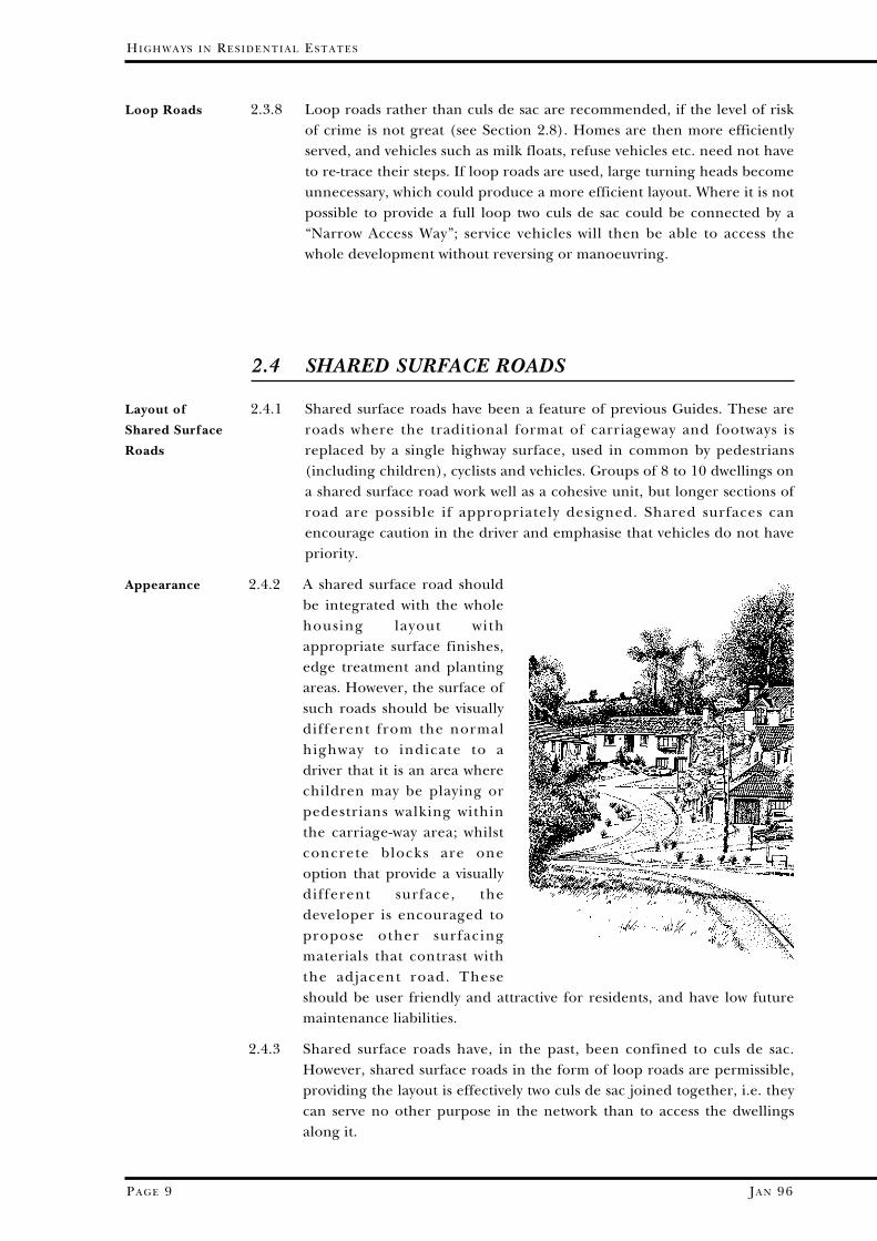
Appearance 2.4.2 A shared surface road shouldbe integrated with the wholehousing layout withappropriate surface finishes,edge treatment and plantingareas. However, the surface ofsuch roads should be visuallydifferent from the normalhighway to indicate to adriver that it is an area wherechildren may be playing orpedestrians walking withinthe carriage-way area; whilstconcrete blocks are oneoption that provide a visuallydifferent surface, thedeveloper is encouraged topropose other surfacingmaterials that contrast withthe adjacent road. Theseshould be user friendly and attractive for residents, and have low futuremaintenance liabilities.
2.4.3 Shared surface roads have, in the past, been confined to culs de sac.However, shared surface roads in the form of loop roads are permissible,providing the layout is effectively two culs de sac joined together, i.e. theycan serve no other purpose in the network than to access the dwellingsalong it.

JA N 96
2.4.4 One very popular form of shared surface road that developers haveprovided in recent years has been the curving cul de sac with grass vergesfronted by open plan gardens. However, open plan is not typical ofDevon, and is not necessary because of highway considerations.Therefore, developers are encouraged to consider other layouts so thatthe street scene can be in harmony with what already exists. This isespecially relevant in villages and historic towns, and Section 2.9 givesmore advice on this.
2.4.5 Some alternatives that are within the definition of “shared surface roads”are as follows, but this list is by no means exhaustive:• mews court type developments where hard surfaces predominate, with
the careful use of raised planters etc; entrances could be given specialtreatment to give the appearance of a private courtyard
• rectangular rather than curvilinear layouts where appropriate to theneighbourhood; hardened surfaces could incorporate visibility splaysetc, with the widths and radii prescribed in section 3.6 beingcontained within the carriageway limits
• layouts where buildings by their irregular layout encroach upon theedge of the highway
• wider carriageways where appropriate, thus avoiding the “tramline”effect of parallel kerb lines.
2.4.6 A particular variant of the shared surface road is the Housing Courtwhere a group of up to 10 dwellings surround communal parking placesserved by a short spine road. Neither the parking places nor anyfootpaths leading from them to dwellings will be adopted. As the spineroad is short (namely 25 metres or less), no turning head is required.Due to the specific requirements of Housing Courts, they are dealt withseparately from shared surface roads in Section 3.
PA G E 10
HI G H W A Y S I N RE S I D E N T I A L A N D CO M M E R C I A L ES T A T E S - DE S I G N GU I D E
PA G E 10
Housing Courts
Various Types
of Layout

JA N 96
2.5 CAR PARKING
HI G H W A Y S I N RE S I D E N T I A L ES T A T E S
PA G E 11
Factors to
Consider in the
Provision of
Car Parking
Sustainability -
The Number of
Spaces to
Provide
Where Car
Parking is to
Take Place
2.5.1 Experience suggests that fewdrivers are prepared to useparking places more than afew metres away from theirdestination. Consequently,the aim should be to makeeach small group of dwellingsself-sufficient in its off streetand on street parkingprovision. The location andnumber of car parking spacesis dependent on a variety offactors:• visual appearance - so that
large areas are notdevoted solely to theparking of cars, nor is thefrontage cluttered byindiscriminately parkedcars
• safety - so that drivers are encouraged, when they park on-street, to doso at locations that do not compromise safety
• crime - off street rear parking courts may well not be used due to thefear of theft from and vandalism to parked cars.
• the promotion of good neighbourliness - so that vehicles are notparked indiscriminately in the carriageway or create difficulties inshared private drives.
These aims, which are sometimes in conflict with one another, have to bebalanced in each development.
2.5.2 Studies have shown that car use is seldom suppressed by reducing theparking provision where the car owner lives. The issue of sustainability isbetter addressed by providing other transport modes rather thanreducing the opportunity to park in a residential area, which could causefurther dangers from congestion and overcrowding of vehicles. Thenumber of spaces recommended per dwelling in the Section 4 of this Partof the Guide is based on studies in Devon’s cities, towns and villages, andshould prove adequate while not over-providing the number of spaces.
2.5.3 As the highway is not intended to be the parking place for residents’ cars,adequate off-street car parking is desirable for all residential areas.Substandard car parking will lead to on-street problems and will be asource of continual nuisance to the residents of the development. Anyprovision should be where the resident would wish to park, i.e. in themost convenient and acceptable place. If on-street resident parking is tobe discouraged, provision for particular properties or groups of housesmust be convenient to those properties and the spaces closer to thedwelling than the highway.
JA N 96
2.5.4 In general, it is recommended that each residential property be providedwith at least two recognised parking spaces within its curtilage. One ofthese spaces may be a garage but the other space should be visible from aliving room or kitchen window to assist surveillance of the parked vehicleby its owner. These spaces would serve both residents and longer stayvisitors (e.g. over night).
2.5.5 Where the parking area is to be shared by a group of dwellings then theseproperties may well be grouped around it. Such natural surveillancediscourages vandalism and reduces vehicle theft. Section 4 of this Part ofthe Guide recommends details and standards of the design of car parkingareas. Again these spaces should be visible from the property, and becloser to the property than the carriageway. Parking areas that arehidden away and not incorporated within the general frontage of theresidential properties are seldom used.
2.5.6 Landscaping parking spaces immediately adjacent to properties will makethe area attractive. Section 4.7 recommends how such landscaping can beincorporated.
2.5.7 Normally, short term casual visitor and servicing parking will be locatedon the adjacent carriageway, depending on the detailed layout. Thus,within any layout, thought should be given to the need to retain shortlengths of highway that can be used for such parking which do notconflict with accesses or junctions. In certain instances widenedcarriageways or specific parking bays may provide casual parking forvisitors, service vehicles etc.
PA G E 12
HI G H W A Y S I N RE S I D E N T I A L A N D CO M M E R C I A L ES T A T E S - DE S I G N GU I D E
PA G E 12
On-Street
Parking
.......Within
Curtilage
Shared Parking
Appearance
JA N 96
HI G H W A Y S I N RE S I D E N T I A L ES T A T E S
PA G E 13
Desire Lines
Safety of the
Cyclist
Provision for
the Blind
Crime
Prevention
2.6 CYCLISTS AND PEDESTRIANS
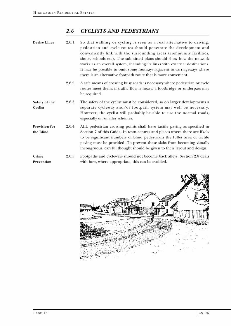
2.6.1 So that walking or cycling is seen as a real alternative to driving,pedestrian and cycle routes should penetrate the development andconveniently link with the surrounding areas (community facilities,shops, schools etc). The submitted plans should show how the networkworks as an overall system, including its links with external destinations.It may be possible to omit some footways adjacent to carriageways wherethere is an alternative footpath route that is more convenient.
2.6.2 A safe means of crossing busy roads is necessary where pedestrian or cycleroutes meet them; if traffic flow is heavy, a footbridge or underpass maybe required.
2.6.3 The safety of the cyclist must be considered, so on larger developments aseparate cycleway and/or footpath system may well be necessary.However, the cyclist will probably be able to use the normal roads,especially on smaller schemes.
2.6.4 ALL pedestrian crossing points shall have tactile paving as specified inSection 7 of this Guide. In town centres and places where there are likelyto be significant numbers of blind pedestrians the fuller area of tactilepaving must be provided. To prevent these slabs from becoming visuallyincongruous, careful thought should be given to their layout and design.
2.6.5 Footpaths and cycleways should not become back alleys. Section 2.8 dealswith how, where appropriate, this can be avoided.

JA N 96 PA G E 14
HI G H W A Y S I N RE S I D E N T I A L A N D CO M M E R C I A L ES T A T E S - DE S I G N GU I D E
PA G E 14
2.7 PUBLIC TRANSPORT
2.7.1 Access by public transport should be considered during the planning of anew residential area. Discussions should be held with the Engineer at anearly stage to see whether bus services may use the estate roads. Whereappropriate, the provision of rail facilities should also be considered.
2.7.2 Factors to be considered are:-• the type and frequency of bus service likely to be provided • the size of bus likely to be used • bus turning and stop-over facilities • the planning of routes in relation to the road hierarchy and existing
bus routes • access to rail facilities where appropriate • the siting of bus stops, including shelters
2.7.3 Bus stops should be safe and accessible, particularly where the bus serviceuses the local distributor rather than entering the estate itself. Within anestate the sit ing of bus stops requires careful planning so thathouseholders do not have cause to complain nor drives and footpathsbecome obstructed, but also so that the distance residents have to walk tothe bus stop is minimised.
2.7.4 In some areas of Devon bus companies use mini-buses that can penetrateestate roads without special provisions. Loop roads and adequateconnections with existing estates will help the operators provide efficientservices. Occasionally, special bus-only links may assist the developmentof local services. Normally services within estates will not require theprovision of laybys or turning areas, but the operator’s lay-over needs mayneed to be considered.
The Role of
Public
Transport
Bus Stops
Operator’s
Needs
JA N 96
HI G H W A Y S I N RE S I D E N T I A L ES T A T E S
PA G E 15
2.8 CRIME PREVENTION
2.8.1 Crime and vandalism are major social problems that affect all areas, bothcity and country, and keeping their level as low as possible should be amajor objective in designing the layout of the estate. “Defensible space”and “natural surveillance” are proven crime prevention measures: there isno doubt that the greatest deterrent to crime is the perceived risk ofbeing caught in the act. The design of the road and footpath layout canhave a significant impact on the opportunities for crime as well as the fearof being a victim of crime.
2.8.2 “Defensible space” is the combination of real or symbolic barriers, whichbring the local environment under the control of its residents. “Naturalsurveillance” can be achieved by creating an atmosphere in which thecriminal feels uncomfortable and exposed.
2.8.3 The advantages of a permeable estate - where there are a number ofaccesses and ways through the development - are clear in highway terms.A permeable layout, however, may not be compatible with the objective ofcrime reduction. Therefore, the layout of the estate should be consideredat an early stage relative to the risk of crime in the locality where thedevelopment is proposed. The Engineer will consult with the PoliceArchitectural Liaison Officer at Police Headquarters, Middlemoor,Exeter, to discuss the level of risk, either real or perceived. The degree ofpermeability through the development will depend on this assessment,and also how footpaths and cycleways are treated.
2.8.4 In any case, natural surveillance gives a sense of local ownership, andshould be over a wider area than the individual home. Although thedifference between public and private space should be clearlyidentifiable, public areas (roads, footpaths and footways) should beoverlooked to give a sense of security. This can be achieved by thecreation of small groups or clusters of dwellings, where each dwelling canbe viewed from others but without detriment to reasonable privacy.Narrowed entrances and gateways (as in the section dealing with trafficcalming) deter intruders from entering the estate.
2.8.5 Dark alleys and narrow footpaths with opportunities to hide engenderfear in many who use them. Therefore, if it is appropriate to includefootpaths and cycleways after consultation with the Police and CountyCouncil, these should be open, with no hidden corners, be overlooked byproperties, adequately lit, and where short lengths are bounded withfences or walls, pedestrians especially should be able to see from end toend.
2.8.6 Sections 2.5 and 4 of this Part of the Guide deal with car parking, andstate that the space provided for residents to park should be off thehighway, preferably within sight of the kitchen or living room window.This has two purposes: firstly, so that the risk of theft is reduced, andsecondly, so that the resident is encouraged to park off the highway.Parking areas that are remote are not used, as the risk and fear of crime isappreciably higher.
Defensible
Space and
Natural
Surveillance
Risk Assessment
How to Achieve
Natural
Surveillance
Footpaths and
Cycleways
Car Parking
JA N 96
HI G H W A Y S I N RE S I D E N T I A L A N D CO M M E R C I A L ES T A T E S - DE S I G N GU I D E
PA G E 16
2.9 SMALL DEVELOPMENTS IN VILLAGES
AND HISTORIC TOWNS
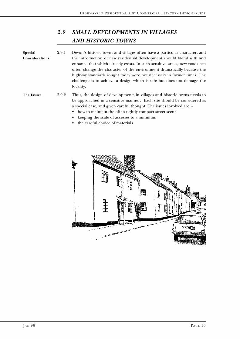
2.9.1 Devon’s historic towns and villages often have a particular character, andthe introduction of new residential development should blend with andenhance that which already exists. In such sensitive areas, new roads canoften change the character of the environment dramatically because thehighway standards sought today were not necessary in former times. Thechallenge is to achieve a design which is safe but does not damage thelocality.
2.9.2 Thus, the design of developments in villages and historic towns needs tobe approached in a sensitive manner. Each site should be considered asa special case, and given careful thought. The issues involved are: -• how to maintain the often tightly compact street scene • keeping the scale of accesses to a minimum • the careful choice of materials.
Special
Considerations
The Issues
JA N 96
PA R T ON E - HI G H W A Y S I N RE S I D E N T I A L ES T A T E S
PA G E 17
2.9.3 Instead of looking at the pages of this Design Guide as a menu fromwhich to choose a road layout appropriate to the number of dwellingsproposed, the designer could return to basic principles. The followingfactors may help to produce a design that fits comfortably in the localenvironment:• normal highway standards are often inappropriate• the safety of pedestrians is a major consideration• access requirements need to be examined from first principles; the
types or size of vehicles accessing the site may have to be limited inorder to achieve adequate design; thus, to what extent access isprovided for service vehicles needs careful consideration, as theirrequirements can dominate the design unnecessarily
• vehicle speeds in the vicinity of the development may be reduced,thereby reducing visibility requirements at the entrance to thedevelopment, possibly by introducing speed restraint or trafficcalming measures on the existing road
• reduced carriageway widths may be possible (compatible with safety etc)• the carriageway alignment should be sympathetic with the character
of the general locality• it may not be necessary to provide parking to the full standard, but
this will depend on the location of the development and theavailability of off-site parking
• materials and finishes should be locally distinctive; the interfacebetween new and existing development may be perceived as the mostprominent aspect of the scheme, and even small changes can have adramatic effect on improving the relationship between the two
• street lighting design should be sympathetic to the setting of thelocality
• special arrangements for services could be considered to avoidexcessive areas of hard surface
2.9.4 Where development is contemplated in sensitive locations, earlydiscussion is recommended with both the local Planning Authority andthe Highway Authority in order to agree the design standards to beadopted.
Need for a
Design Brief
Basic Principles
of Design

Speed Type Name Number of CommentDwellings
Grouped communalparking
Housing Court <10 dwellings maximum length25 metres;
no footways
Special surfaces
Shared <25 for cul de sac required;
15mph Surface no footways;
Access Way <50 for loop road maximum length100 metres;
(300 metres if loop)
Narrow providing Single track 15mph Access access to road with
Way <50 dwellings passing places
With footways;Traditional <30 for cul de sac maximum
15mph Access lengthWay <50 if loop 150 metres,
(300 metres if loop)
In form of loop>30 but <50 for if between
cul de sac, 50 and 100 dwellings,20mph Access Road >50 otherwise or with two accesses
>100 if two accesses to existing road system<300 if over 100 dwellings
(see DB32, paragraph 2.22)
25mph Transition Road >300 dwellings
Also please refer to notes on opposite page
JA N 96
HI G H W A Y S I N RE S I D E N T I A L A N D CO M M E R C I A L ES T A T E S - DE S I G N GU I D E
PA G E 18
SECTION 3
THE DETAILED CHARACTERISTICS
OF RESIDENTIAL ROADS
3.1 THE ROAD NETWORK
3.1.1 The roads in a proposed development should be appropriate to thenumber of dwellings being served, and the number of accesses on to theexisting road network. The road appropriate to the number of dwellingsbeing served should be selected from the table below, for which furtherdetails are given in the Sections following.
R4
R33
R32
R31
R2
R1

JA N 96
PA R T ON E - HI G H W A Y S I N RE S I D E N T I A L ES T A T E S
PA G E 19
Notes: • estates of more than 100 dwellings should normally have more than one access to the Local Distributor Road
• designers are encouraged to use various combinations or hybrids of these roads to achieve a practical layout
• design of Distributor Roads (i.e. where no frontage access to dwellings is normally permitted) is outside the scope of this guide
• reference should be made to Section 2.9 for small developments in villages and historic towns
• inter-connection of adjoining residential estates or areas should also be considered, which could provide additional access routes
However, it is important that the residential street system does not provide a “through route” or“rat run” that is attractive to extraneous traffic.
LocalCentre
Cycleway andFootpath
PublicOpenSpace
R2
R1
R2
R33
R33
R33
R2
R33
R32
R4
R2
R31
R2
R31
R2
R2
R1
LocalDistributor
Road
KEY
R1 - Residential Transition Road
R2 - Residential Access Road
R31 - Traditional Access Way
R32 - Narrow Access Way
R33 - Shared Surface Access Way
R4 - Housing Court
PublicOpenSpace
Building outlines for
illustrative purposes only
ILLUSTRATIVE ROAD LAYOUT FOR
RESIDENTIAL ESTATES
JA N 96
HI G H W A Y S I N RE S I D E N T I A L A N D CO M M E R C I A L ES T A T E S - DE S I G N GU I D E
PA G E 20
3.2 TYPE R1 RESIDENTIAL TRANSITION ROAD
3.2.1 Residential Transition Roads provide a link between the existing localdistributor roads and access roads within the development. TransitionRoads are thus needed for developments of between 300 and 600dwellings.
3.2.2 Due to the number of dwellings being served by a Residential TransitionRoad, it is more than likely that a right turn lane or similar provision willbe needed on the Distributor Road.
3.2.3 Direct access to individual dwellings is acceptable provided there is anon-site car turning facility separate from the minimum car parking andgarage space requirements.
Function
Access
Detailed
Characteristics
of These Roads
Are
Design speed 40 kph (25 mph) or less
Maximum length 100m; (where geography requires the TransitionRoad to be longer, speed restraints should be nomore than 100m apart)
Carriageway 5.5m minimum, widened on bends as necessary Width (see para 7.3.8)
Junction Radii 10m at junction with local distributor road etc.
Kerbs 125mm upstand, traditional design, 12mmupstand at vehicle entrances and 6mm upstand atpedestrian crossing points
Footways normally required on both sides of the road witha minimum width of 2.0m
Verges a grass verge or ground cover planting, ofminimum width 2.0m, may be provided betweenthe footway and the carriageway; in somelocations a planter may be appropriate
Gateways as this road provides a main access into largerresidential areas it should contain a gateway (see Section 5.2) to inform drivers that they areentering a different environment
Services Statutory Undertakers’ services will normally beprovided in the footway or verge (see Section 7.9).

PA R T ON E - HI G H W A Y S I N RE S I D E N T I A L ES T A T E S
PA G E 21 JA N 96
3.3 TYPE R2 ACCESS ROAD
3.3.1 Access Roads may serve up to 300 dwellings:-• if it serves between 30 and 50 dwellings it could be in the form of a cul
de sac.• and if from 50 to 100 dwellings it will preferably form a loop road
When it serves more than 100 dwellings, there should be at least twoaccesses into the estate.
3.3.2 Direct access to dwellings is permitted but adequate non-remote off streetparking facilities are required for each dwelling (see paras. 2.5.1 to 2.5.3).
3.3.3 The Access Road may extend into a Type R31, R32 or R33 road, provided:i) a turning facility is provided at the limit of the Access Road to avoid
traffic having to turn in the Type R32 or R33 road ii) the transitional alignment is such as to reduce the vehicle speeds to
near walking pace, oriii)if straight, a suitable gateway calming feature is provided at the
transition.
Function
Access
Extensions
from Access
Roads
* in certain instances the width of a footway or verge may be reduced, for instance, if (i) pedestrian
flows are low or (ii) at particular features, where a reduction to 1.35m may be appropriate, provided
visibility and safety requirements are not prejudiced, and services do not thereby have to be placed in
the carriageway.
Detailed
Characteristics
of These Roads
Are
Design speed 32 kph (20 mph)
Spacing of Speed no more than 60m to 80m spacing Restraint Features
Carriageway Width 5.5m minimum, widened on bends as necessary (see para 7.3.8)
Junction Radii 10m at junction with a Distributor Road, existing Classified Road whose function is that of aDistributor Road, or Type 1 Road, or6m at junctions with other Type R2 Roads
Kerbs 125mm upstand, traditional design,12mm upstand at vehicle entrances, and6mm upstand at pedestrian crossing points
Footways normally required with a width of 2.0m* whereproperties front on to this road, unless it is clearthat there is unlikely to be any pedestrian traffic
Verges required when a footway is not essential, havingsufficient width to contain services (generally 2.0m is required)*
Gateways are required where a Type R2 road is accesseddirectly from the existing local road network
Services Statutory Undertakers’ services will normally beprovided in the footway or verge (see Section 7.9).
JA N 96 PA G E 22
HI G H W A Y S I N RE S I D E N T I A L A N D CO M M E R C I A L ES T A T E S - DE S I G N GU I D E
3.4 TYPE R31 TRADITIONAL ACCESS WAY
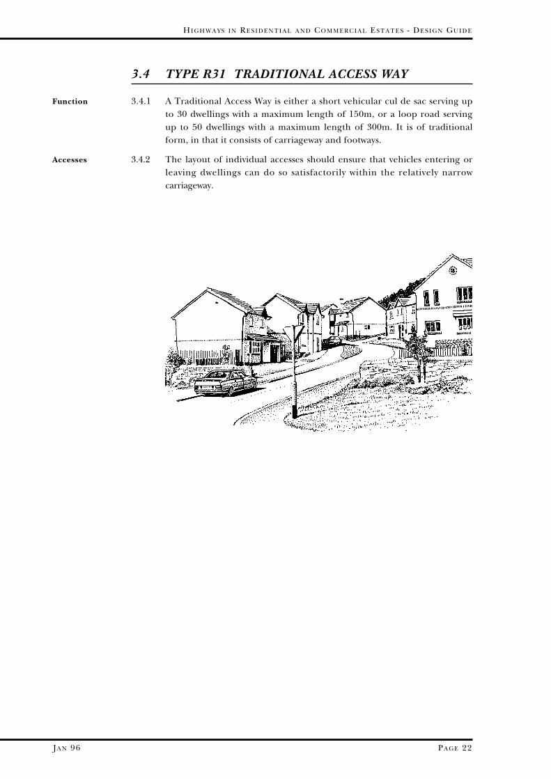
3.4.1 A Traditional Access Way is either a short vehicular cul de sac serving upto 30 dwellings with a maximum length of 150m, or a loop road servingup to 50 dwellings with a maximum length of 300m. It is of traditionalform, in that it consists of carriageway and footways.
3.4.2 The layout of individual accesses should ensure that vehicles entering orleaving dwellings can do so satisfactorily within the relatively narrowcarriageway.
Function
Accesses

PA R T ON E - HI G H W A Y S I N RE S I D E N T I A L ES T A T E S
PA G E 23 JA N 96
Detailed
Characteristics
of These Roads
Are
Design speed 24 kph (15 mph)
Maximum length 150m if a cul de sac serving up to 30 dwellings300m if a loop road serving up to 50 dwellings
Spacing of Speed the spacing of speed restraints is to be 40m withRestraint Features the exception that, for a cul de sac up to 60m in
length, no speed restraint is required, while for a60m-100m cul de sac a mid-point restraint isrequired
Carriageway Width 4.8m minimum except at turning heads and widened on bends
Junction Radii 10m if off Type R1 or existing Classified Roadwhose function is that of a Distributor Road, or6m at junctions with other residential roads (i.e. R2, R31 and R32 )
Centre Line Radii 10m minimum
Kerbs traditional with 125mm maximum upstand,12mm upstand at vehicular crossings and 6mm upstand at pedestrian crossing points
Footways normally required with a width of 2.0m* whereproperties front on to this road, unless it is clearthat there is unlikely to be any pedestrian traffic
Verges not required where footways are provided; if a footwayis omitted (see above), a verge is to replace it*
Turning Heads required for all culs de sac; they may be ofinformal shape providing they are capable ofcontaining a standard turning head within theiroutline (see para 7.3.12)
Headroom 4.5m under archways Minimum
Services Statutory Undertakers’ services will normally beprovided in the footway or verge (see Section 7.9).
* in certain instances the width of a footway or verge may be reduced, for instance, if(i) pedestrian flows are low or (ii) at particular features, where a reduction to 1.35mmay be appropriate, provided visibility and safety requirements are not prejudiced,and services do not thereby have to be placed in the carriageway.
JA N 96
HI G H W A Y S I N RE S I D E N T I A L A N D CO M M E R C I A L ES T A T E S - DE S I G N GU I D E
PA G E 24
3.5 TYPE R32 NARROW ACCESS WAY
3.5.1 A Narrow Access Way is a short single track link road, or an intermediatelength of Access Road, that leads to no more than 50 dwellings. A NarrowAccess Way will only be appropriate off a Local Distributor or an existingClassified Road whose function is that of a Distributor Road inexceptional circumstances. Where, of necessity, a Narrow Access Way is ofsome length, measures should be included so that the design speed is notexceeded.
3.5.2 Direct access to dwellings will not be permitted, due to the restrictedwidth of the road.
3.5.3 The junction between a Narrow Access Way and an Access Way where theformer has priority must be designed to provide a passing bay and anadequate entrance and exit to and from the Access Way (see fig 7.2.4 VI).Junctions and passing bays along the Narrow Access Road must beintervisible in accordance with Appendix 2 of Design Bulletin 32.
3.5.4 Narrow Access Ways can occasionally be blocked by vehicle breakdown orroad maintenance. Therefore, alternative routes should always exist.However, if the road is, of necessity, part of what is effectively a cul desac, the layout should include an emergency link to another road to allowthe obstruction to be by-passed.
Function
Accesses
Junctions
Emergency Link
Detailed
Characteristics
of These Roads
Are
Design speed 24 kph (15 mph)
Carriageway Width 3m minimum with local widening where servicesunavoidably cross, and widening on bends
Junction Radii 6m
Kerbs 125mm upstand, and6mm upstand at pedestrian crossing points
Footways and At least one footway is to be provided, in whichVerges case a verge is to be provided on the other side;
both the footway and verge are to be 2.0m wide.
Services to be located in the footway/services’ marginswith the minimum of carriageway crossings; allsewers and highway drains should be located inthe carriageway.
JA N 96
PA R T ON E - HI G H W A Y S I N RE S I D E N T I A L ES T A T E S
PA G E 25
3.6 TYPE R33 SHARED SURFACE ACCESS WAY
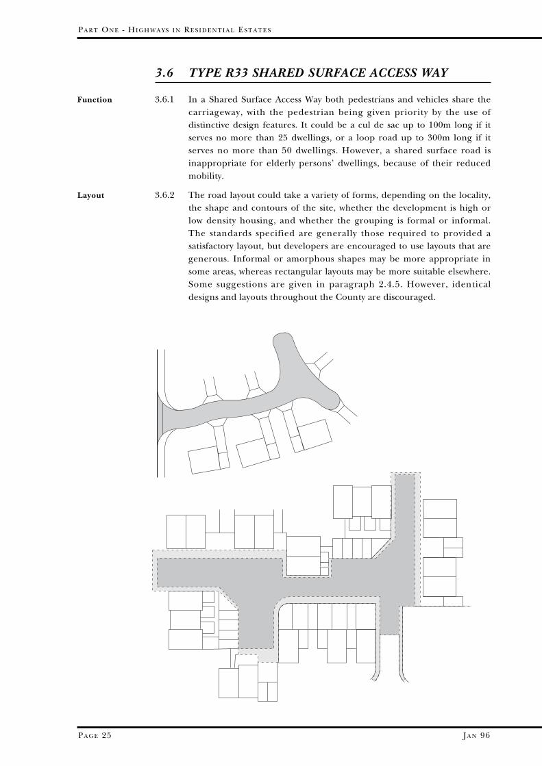
3.6.1 In a Shared Surface Access Way both pedestrians and vehicles share thecarriageway, with the pedestrian being given priority by the use ofdistinctive design features. It could be a cul de sac up to 100m long if itserves no more than 25 dwellings, or a loop road up to 300m long if itserves no more than 50 dwellings. However, a shared surface road isinappropriate for elderly persons’ dwellings, because of their reducedmobility.
3.6.2 The road layout could take a variety of forms, depending on the locality,the shape and contours of the site, whether the development is high orlow density housing, and whether the grouping is formal or informal.The standards specified are generally those required to provided asatisfactory layout, but developers are encouraged to use layouts that aregenerous. Informal or amorphous shapes may be more appropriate insome areas, whereas rectangular layouts may be more suitable elsewhere.Some suggestions are given in paragraph 2.4.5. However, identicaldesigns and layouts throughout the County are discouraged.
Function
Layout
JA N 96
HI G H W A Y S I N RE S I D E N T I A L A N D CO M M E R C I A L ES T A T E S - DE S I G N GU I D E
PA G E 26
Access
Verges
Design speed 24 kph (15 mph)
Maximum 100m if a cul de sac serving up to 25 dwellings length 300m if a loop road serving up to 50 dwellings
Spacing of the spacing of speed restraints is to be 40m with theSpeed exception that, for a cul de sac up to 60m in length, noRestraint speed restraint is required; for a 60m-100m cul de sac aFeatures mid-point restraint is required
Entrance ramped to reduce speeds and indicate to a driver thathe is entering a different and mixed pedestrian/vehicular environment; a strong physical definition ofthe changing character of the space is essential; theentrance ramp shall take the form shown in figure7.2.4 III, IV, or V in special circumstances
Carriageway the width may vary from 4.8m to 6.0m (widened onWidths bends in accordance with para 7.3.8), laid out either(see Note *) formally or informally (see 3.6.2 above)
Junction Radii 4.0m with Type R31, (see Note *) 6.0m with Type R2 and
6m or 10m with Type R1, a Classified Road or a LocalDistributor Road (depending on the character of themain road)
Detailed
Characteristics
of These Roads
Are
3.6.3 Normally a Shared Surface Access Way will not be permitted directly off aLocal Distributor or existing Classified Road that functions as a DistributorRoad; however, it is recognised that there may be occasional situationswhere such a case could arise, e.g. within Conservation Areas, the NationalParks, or where such a treatment would be in sympathy with the characterof the village. In particular, small developments with access from attractivevillage streets will merit special consideration (see section 2.9).
3.6.4 Vehicles entering individual accesses should be able to do so withouthaving to drive onto any grass verges; it may be that accesses could belocated at points where the carriageway has been increased in width.They should also be splayed at their junction with the carriageway.
3.6.5 Verges and hardened edge strips provide visibility from accesses andaccommodate services and therefore need to be part of the highway. Theymay be contiguous with the front gardens, but should be kept clear of allobstructions so that access may be obtained to the services underneath;obstructions placed after adoption may be removed by the HighwayAuthority.
3.6.6 The frontagers are expected to maintain the grass verges adjacent totheir gardens, even though they are part of the highway. However, grassverges are generally unacceptable at the sides of properties as thelikelihood of attention from the residents is reduced.

JA N 96
PA R T ON E - HI G H W A Y S I N RE S I D E N T I A L ES T A T E S
PA G E 27
Centre Line minimum 10mRadii (see Note *)
Kerbs should be less formal than standard roads (see para 7.3.14), namely 40mm upstand reduced to12mm at vehicle entrances and 6mm upstand atpedestrian entrance points
Footway not required
Verges • a width of 2.0m should accommodate the full range ofservices
• a demarcation or a construction joint should beprovided in all drives and entrance paths
• very short lengths of grass verge are not viable, sothat the minimum acceptable length measured at thekerb line is 3 metres; over shorter lengths, suitablyhardened verges of a contrasting material that is likeneither carriageway nor vehicle crossing may beprovided
• verge markers will be required as described in para 7.7.14
Turning heads required for all cul de sac as shown in para 7.3.12
Headroom 4.5m minimum under archways
Surface finish must contrast visually with the road surface of theconventional Access Road that it joins (see figures 7.2.4III, IV and V) and be of a type that will remain visuallydistinctive throughout its life
Vehicle all crossings in any one street shall be constructed ofCrossing the same material; acceptable materials (subject to the
views of the Planning Authority) are either bitumen orthe wide variety of concrete block products
Services Statutory Undertakers’ services will normally beprovided in the verge (see Section 7.9).
* the carriageway widths, radii and turning head dimensions may be ofinformal (rectangular or curvilinear) shape providing they are capable ofcontaining the standard dimensions given within their outline.

JA N 96
HI G H W A Y S I N RE S I D E N T I A L A N D CO M M E R C I A L ES T A T E S - DE S I G N GU I D E
PA G E 28
3.7 TYPE R4 HOUSING COURTS
3.7.1 A Housing Court is a maximum of 10 dwellings around communalparking spaces that front on to a short spine road. These parking spacesmust not be assigned to individual dwellings; the Engineer will need tobe satisfied that there are suitable arrangements to prevent residentsusing spaces for the storage of caravans, boats, building materials etc, sothat what was designed as communal parking remains as such. The layoutof the courtyard should be enclosed on the frontage to the main road togive the impression of privacy and to encourage careful driver behaviour.
3.7.2 Cars are able to manoeuvre in a Housing Court as the central spine roadis 6 metres wide. However, refuse and other vehicles will not be able toturn within a Court, and will generally park outside in the main road.Therefore, the layout of the main road should allow for service vehicleparking.
3.7.3 A Housing Court should not access directly on to a Type R1 road, a LocalDistributor, Collector or Access Road that serves as a through route,because of the dangers of larger vehicles serving the Court having to parkor reverse on to the major route.
3.7.4 If the distance that refuse (for example) has to be carried from adwelling’s curtilage is to be kept to a reasonable minimum, the length ofthe spine road measured along its centre line from the channel of themain road should be no greater than 25 metres. Under thesecircumstances, no turning head is required.
3.7.5 No footway is to be provided surrounding the parking spaces; however,designers may choose to provide a hard strip behind the parking spacesfor vehicle overhang and protection of adjacent soft areas. Footpathscould then lead to groups of up to three dwellings.
3.7.6 Only the spine road will be adopted; the parking spaces and thefootpaths to the dwellings will not be adopted. There is to be nocommunal parking within the highway envelope.
3.7.7 Services are to be located in a 2 metre wide zone on one side of the spineroad, within its 6 metre width. From this, connections to two or threeproperties may be made along the footpaths that lead to the dwellings.
Function
Access and
Turning Facility
Length
No Footway
Adoption
Services

JA N 96
PA R T ON E - HI G H W A Y S I N RE S I D E N T I A L ES T A T E S
PA G E 29
Detailed
Characteristics
of These Roads
Are
Entrance a gateway as well as a ramp is to be provided toreduce vehicle speeds and indicate a mixedpedestrian/vehicle environment; the entranceramp shall take the form shown in para 7.2.4 IV
Maximum Length 25m measured from the nearside edge of themain road along the centre line of the spine road
Entrance 4.8m minimum Carriageway Width
Footways not required
Parking Space and 4.8m x 2.4m parking spaces Aisle Dimensions 6.0m wide spine road
Junction Radii 6.0m with Type R2, and4.0m with Type R31
Kerbs entrance kerbs - see diagram 7.2.4 IV12mm upstand for the kerbs defining the front edgeof the parking space
Surface Finish must contrast visually with the road surface of theconventional access road; (car parking spacefinishes could be of a darker colour to minimisethe visual effect of oil stains)
Services Statutory Undertakers’ services are to be locatedin a 2 metre wide zone at one side of the spineroad, within its 6 metre width.

JA N 96
HI G H W A Y S I N RE S I D E N T I A L A N D CO M M E R C I A L ES T A T E S - DE S I G N GU I D E
PA G E 30
3.8 CYCLEWAYS
3.8.1 Cycleways are routes for cyclists that motorised vehicles are not permitted touse (with the exception of emergency and maintenance vehicles);pedestrians, however, do have the right to use them. They may be adjacentto footpaths, or the route may be unsegregated (i.e. shared between cyclistand pedestrian with no separation by kerb or white line) where flows areexpected to be low, but each situation must be considered on its own merits.
3.8.2 Unsegregated paths should generally only be provided where pedestriansregularly need to cross over them. The width of unsegregated pathsshould normally be 2.5m, but under certain circumstances localnarrowing to 2.0m may be allowed.
3.8.3 Segregated footpaths and cycleways should be distinguished from each otherby surface colour, texture, central white line or even upstand kerb in moreheavily used sections. The surface treatment will be determined by consultationwith the Engineer, who will have regard to the type of surface treatment usedon other cycle routes in the neighbourhood when giving approval. The widthof each section (i.e. both cycleway and footpath) shall be 1.5 metres if boundedby a verge, or 1.75m if bounded by fence, wall or the like.
3.8.4 Minimum forward visibility should be 20m, increased to 30m where thedownhill gradient exceeds 5%.
3.8.5 Junctions with vehicular carriageways are to be laid out as in section7.2.4. The design of such layouts should bear in mind the principle thatthe cycleway is a carriageway. Thus, proximity to other junctions, junctionvisibility and junction detailing (give way lines etc) need careful thought.The visibility requirements at priority junctions are as set out inparagraph 7.2.1, using the appropriate “y” distances and an “x” distanceof 1.5 metres. Where a cycleway crosses a footpath, the cyclist hasprecedence, and the appropriate “x” and “y” visibility distances for thepedestrian are 1.0m and 20m respectively.
3.8.6 The minimum headroom over cycleways should be 2.75 metres.
Function
Unsegregated
Cycle Paths
Segregated
Cycle Paths
Visibility
Junctions
Headroom
Drainage
Security
3.8.7 Provision should be made for thedrainage of cycleways. Whereadjoining land is to be adopted aspublic open space by the LocalAuthority, it may not be necessaryto provide positive drainage, butthis will depend on whether thecycleway is on an embankment,side slope or cutting.
3.8.8 Cycleways should be pleasant touse in all cases, with no recessesthat would cause concern forpersonal safety. Adequate lightingshall be provided.
JA N 96
PA R T ON E - HI G H W A Y S I N RE S I D E N T I A L ES T A T E S
PA G E 31
3.9 FOOTPATHS
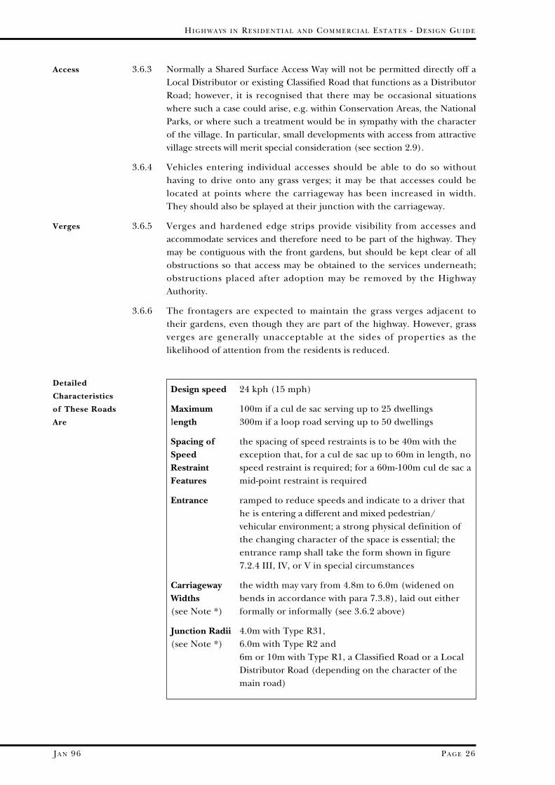
3.9.1 Footpaths are defined as pedestrian routes located away fromcarriageways.
3.9.2 Footpaths to locations outside the residential development should followpedestrian desire lines, by linking features that generate or attractpedestrian traffic e.g. shops, play areas, social centres, work places etc.Where the footpath crosses major roads the crossing points must be safeand convenient, as many of the users of pedestrian routes will bechildren, parents with prams, and the elderly. If physical segregation isnot provided, barriers and other safety measures may be required.(Further guidance for the provision of crossing facilities for the blind aregiven in Section 7 of this Part of the Guide and Department of theEnvironment Disability Unit Circular 1/91).
3.9.3 All footpaths should be direct and should be wide enough to suit theexpected level of use. A minimum width of 2.0m is normally required,but wider paths may be required where services lie beneath them. Theirwidths may vary in the following circumstances:• where less than the full range of services has to be accommodated and
pedestrian traffic is very low, widths may be reduced to a minimum of1.35m provided that frequent 2.0m wide passing places are provided,particularly where lamp columns and signs are located
• where access by emergency services or statutory undertakers’ vehiclesis required footpaths need to be strengthened and widened to aminimum unobstructed width of 2.75m
• where footpaths are the only means of access to dwellings the Fire andRescue Service must be consulted on the clear widths required
Function
Width
JA N 96
HI G H W A Y S I N RE S I D E N T I A L A N D CO M M E R C I A L ES T A T E S - DE S I G N GU I D E
PA G E 32
• where footpaths link housing areas or form part of a major pedestriannetwork they should have a minimum width of 2.5m
• where a footpath is to be used by both pedestrians and cyclists (seesection 3.8)
• where footpaths pass between fences, walls and buildings, the widthmay need to be increased to accommodate the likely level ofpedestrian traffic, and to give the feeling of personal security.
3.9.4 The minimum headroom over footpaths should be 2.4 metres
3.9.5 Footpaths should be easy to use throughout the network for those withprams and wheelchairs. Steps should be avoided wherever possible but, ifunavoidable, the provision of suitable ramps or alternative routes to caterfor prams and wheelchairs may well be necessary.
3.9.6 To give a feeling of greater security, footpaths should be open, with nohidden corners, well lit after dark and should be overlooked by dwellings.The pedestrian should be able to see from end to end.
3.9.7 Provision should be made for the drainage of footpaths. However, whereadjoining land is to be adopted as public open space by the LocalAuthority, it may not be necessary to provide positive drainage, but thiswill depend on whether the footpath is on an embankment, side slope orcutting.
Headroom
Ease of Use
Security
Drainage

JA N 96
PA R T ON E - HI G H W A Y S I N RE S I D E N T I A L ES T A T E S
PA G E 33
3.10 PRIVATE DRIVES
SERVING UP TO THREE DWELLINGS
3.10.1 Private drives may serve up to three dwellings provided there is adequateprovision for parking and turning private vehicles, including vehicles ofup to 3.5 tonnes maximum laden weight. If more than three dwellingsare served off a private drive problems are likely to created for futureresidents; therefore, private drives serving more than 3 dwellings are notacceptable.
3.10.2 Residents should not be inconvenienced by awkward or substandardlayouts that have been devised to avoid extending the length of adoptableroads. Communal or shared vehicle turning and servicing areas should bepaved in a contrasting material to the individual private access drives andparking spaces.
Function
3.10.3 Adequate parking spaces to the normal standard are required for eachdwelling. There may need to be additional parking spaces for largervehicles, caravans, boats, etc.
3.10.4 Private drives may give direct access to dwellings from R1 ResidentialTransition Roads, Type R2 Access Roads and Type R31/R33 Traditionalor Shared Surface Access Ways.
3.10.5 Gradients should ideally not be greater than 7%. Cars should not groundwhen using private drives, so it is recommended that the first 6m shouldnot be steeper than 5% to avoid this problem.
3.10.6 Adequate drainage within the driveway must be provided where thegradient is such that rain water would otherwise flow on to the adjacenthighway.
Access
Parking
Gradients
Drainage
JA N 96
HI G H W A Y S I N RE S I D E N T I A L A N D CO M M E R C I A L ES T A T E S - DE S I G N GU I D E
PA G E 34
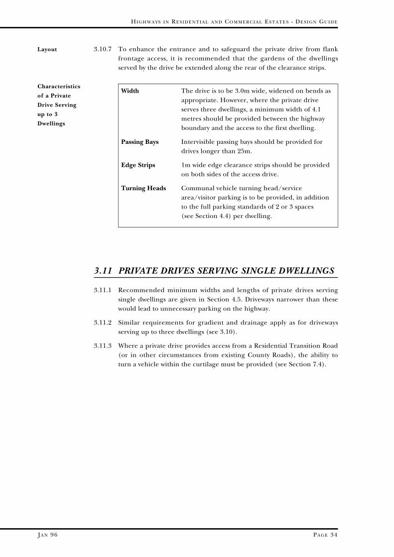
3.10.7 To enhance the entrance and to safeguard the private drive from flankfrontage access, it is recommended that the gardens of the dwellingsserved by the drive be extended along the rear of the clearance strips.
Layout
Width The drive is to be 3.0m wide, widened on bends asappropriate. However, where the private driveserves three dwellings, a minimum width of 4.1metres should be provided between the highwayboundary and the access to the first dwelling.
Passing Bays Intervisible passing bays should be provided fordrives longer than 25m.
Edge Strips 1m wide edge clearance strips should be providedon both sides of the access drive.
Turning Heads Communal vehicle turning head/servicearea/visitor parking is to be provided, in additionto the full parking standards of 2 or 3 spaces (see Section 4.4) per dwelling.
Characteristics
of a Private
Drive Serving
up to 3
Dwellings
3.11 PRIVATE DRIVES SERVING SINGLE DWELLINGS
3.11.1 Recommended minimum widths and lengths of private drives servingsingle dwellings are given in Section 4.5. Driveways narrower than thesewould lead to unnecessary parking on the highway.
3.11.2 Similar requirements for gradient and drainage apply as for drivewaysserving up to three dwellings (see 3.10).
3.11.3 Where a private drive provides access from a Residential Transition Road(or in other circumstances from existing County Roads), the ability toturn a vehicle within the curtilage must be provided (see Section 7.4).
SECTION 4
CAR PARKING
4.1 INTRODUCTION
4.1.1 Car parking off the highway is a matter for the Local Planning Authority.However, badly-designed parking spaces have had an impact on thehighway because on-street parking is preferred by residents where the off-street layouts are poor. The following recommendations are made,therefore, in order to assist in providing layouts that are mutuallyacceptable to both the Local Planning and Highway Authorities, and alsothe future residents.
4.1.2 Randomly parked cars intrude on to the street scene in many older roadsand streets within Devon’s cities, towns and villages, often contributing tothe dangers faced by other road users. In section 2.5 it is recommendedthat the layout of new development should provide adequate andconvenient car parking off-street and within the vicinity of the dwelling.Parking on the carriageway is to be discouraged because of the narrowerroad widths in residential streets.
4.1.3 However, there will always be casual callers and service vehicle drivers whofind it necessary to park on the carriageway. Therefore, carriageway layoutdesign should also accommodate this short term need by local wideningetc.
4.2 LOCATION OF OFF-STREET PARKING SPACES
4.2.1 The risk of vandalism and theft increases greatly the further the vehicle isaway from the dwelling. Layouts that include parking within the curtilageof each dwelling or conveniently located nearby are preferred.
4.2.2 If communal parking areas are provided, it is better if these areimmediately outside the dwellings they serve. Remote courtyards andparking areas are generally not used by residents as they become a targetfor vandals, and thus are considered unacceptable for new estates.
4.2.3 Whether parked within the curtilage or in a nearby parking space, it issuggested that the parked car should be within sight of a kitchen or livingroom window of the dwelling the space serves. For instance, even ifwithin curtilage, a parking space may be hidden on the far side of agarage and thus is not within sight of the dwelling; or, in the case ofcommunal parking areas, a courtyard to the rear of one or two of thedwellings may be obscured from both the remainder of the houses servedand the passing pedestrian. High fences or boundary walls may well
PA R T ON E - HI G H W A Y S I N RE S I D E N T I A L ES T A T E S
PA G E 35 JA N 96
Convenient,
Secure
Remote Spaces
Are Not Used
Parked Vehicles
Should Be
Visible

render spaces invisible from the dwelling even where parking is providedoff-highway and close to the dwelling, thus encouraging drivers to parkon the highway.
4.2.4 In developments where communal parking is to predominate, theparking provision should be so laid out that it is obvious which smallgroup of spaces is intended to serve which group of dwellings. Toencourage the residents to use the spaces provided, they should ideallybe closer to their front door than any possible parking opportunity onthe highway. Spaces remote from the dwellings merely introduced tomake up the numbers are not recommended.
4.3 ON-STREET PARKING
4.3.1 Casual callers and service vehicles will always need to park on thehighway. Specific allowance is to be made for this by the provision ofparking bays, or by minor local widening of the carriageway, at locationswhere the least conflict with private drives would occur. Section 4.4recommends the number of spaces that should be provided; it should benoted that the number of off-street spaces does not include such casualcallers, and thus are to be in addition to that provided for each dwelling.Such on-street parking should not conflict with visibility or safety.
HI G H W A Y S I N RE S I D E N T I A L A N D CO M M E R C I A L ES T A T E S - DE S I G N GU I D E
PA G E 36JA N 96
4.4 RECOMMENDED NUMBER OF
PARKING SPACES
PA R T ON E - HI G H W A Y S I N RE S I D E N T I A L ES T A T E S
PA G E 37 JA N 96
... if Parking is
within Curtilage
... if Parking is
Communal
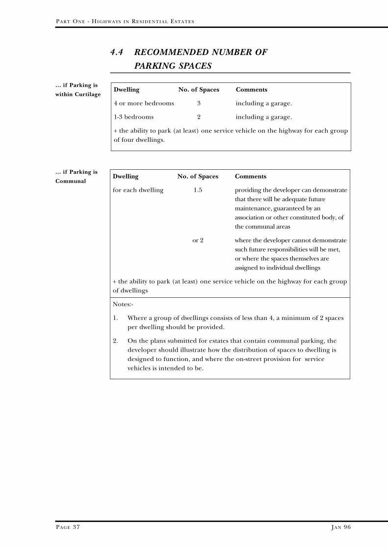
Dwelling No. of Spaces Comments
4 or more bedrooms 3 including a garage.
1-3 bedrooms 2 including a garage.
+ the ability to park (at least) one service vehicle on the highway for each groupof four dwellings.
Dwelling No. of Spaces Comments
for each dwelling 1.5 providing the developer can demonstratethat there will be adequate futuremaintenance, guaranteed by anassociation or other constituted body, ofthe communal areas
or 2 where the developer cannot demonstratesuch future responsibilities will be met,or where the spaces themselves areassigned to individual dwellings
+ the ability to park (at least) one service vehicle on the highway for each groupof dwellings
Notes:-
1. Where a group of dwellings consists of less than 4, a minimum of 2 spacesper dwelling should be provided.
2. On the plans submitted for estates that contain communal parking, thedeveloper should illustrate how the distribution of spaces to dwelling isdesigned to function, and where the on-street provision for servicevehicles is intended to be.
4.5 PARKING SPACE DIMENSIONS
WITHIN CURTILAGE
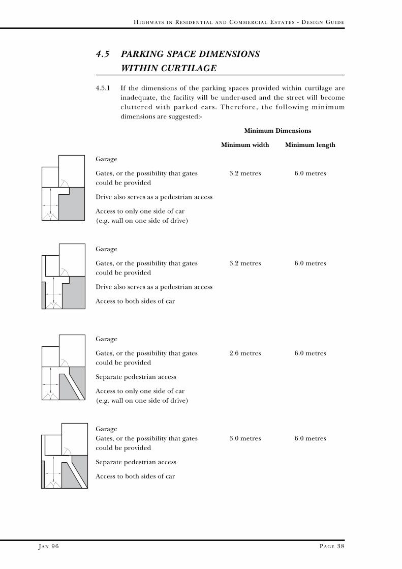
4.5.1 If the dimensions of the parking spaces provided within curtilage areinadequate, the facility will be under-used and the street will becomecluttered with parked cars. Therefore, the following minimumdimensions are suggested:-
Minimum Dimensions
Minimum width Minimum length
Garage
Gates, or the possibility that gates 3.2 metres 6.0 metrescould be provided
Drive also serves as a pedestrian access
Access to only one side of car (e.g. wall on one side of drive)
Garage
Gates, or the possibility that gates 3.2 metres 6.0 metrescould be provided
Drive also serves as a pedestrian access
Access to both sides of car
Garage
Gates, or the possibility that gates 2.6 metres 6.0 metrescould be provided
Separate pedestrian access
Access to only one side of car (e.g. wall on one side of drive)
GarageGates, or the possibility that gates 3.0 metres 6.0 metrescould be provided
Separate pedestrian access
Access to both sides of car
HI G H W A Y S I N RE S I D E N T I A L A N D CO M M E R C I A L ES T A T E S - DE S I G N GU I D E
PA G E 38JA N 96
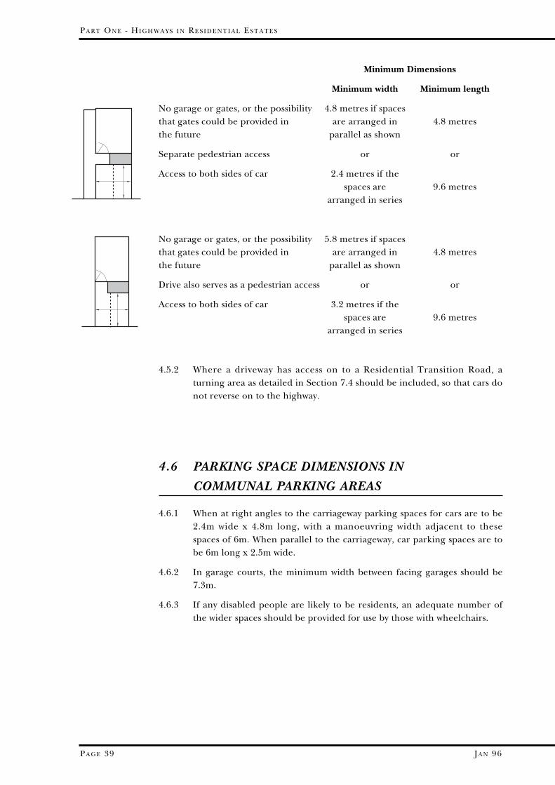
Minimum Dimensions
Minimum width Minimum length
No garage or gates, or the possibility 4.8 metres if spacesthat gates could be provided in are arranged in 4.8 metresthe future parallel as shown
Separate pedestrian access or or
Access to both sides of car 2.4 metres if thespaces are 9.6 metres
arranged in series
No garage or gates, or the possibility 5.8 metres if spacesthat gates could be provided in are arranged in 4.8 metresthe future parallel as shown
Drive also serves as a pedestrian access or or
Access to both sides of car 3.2 metres if the spaces are 9.6 metres
arranged in series
4.5.2 Where a driveway has access on to a Residential Transition Road, aturning area as detailed in Section 7.4 should be included, so that cars donot reverse on to the highway.
4.6 PARKING SPACE DIMENSIONS IN
COMMUNAL PARKING AREAS
4.6.1 When at right angles to the carriageway parking spaces for cars are to be2.4m wide x 4.8m long, with a manoeuvring width adjacent to thesespaces of 6m. When parallel to the carriageway, car parking spaces are tobe 6m long x 2.5m wide.
4.6.2 In garage courts, the minimum width between facing garages should be7.3m.
4.6.3 If any disabled people are likely to be residents, an adequate number ofthe wider spaces should be provided for use by those with wheelchairs.
PA R T ON E - HI G H W A Y S I N RE S I D E N T I A L ES T A T E S
PA G E 39 JA N 96
4.7 CAR PARKING AND LANDSCAPE
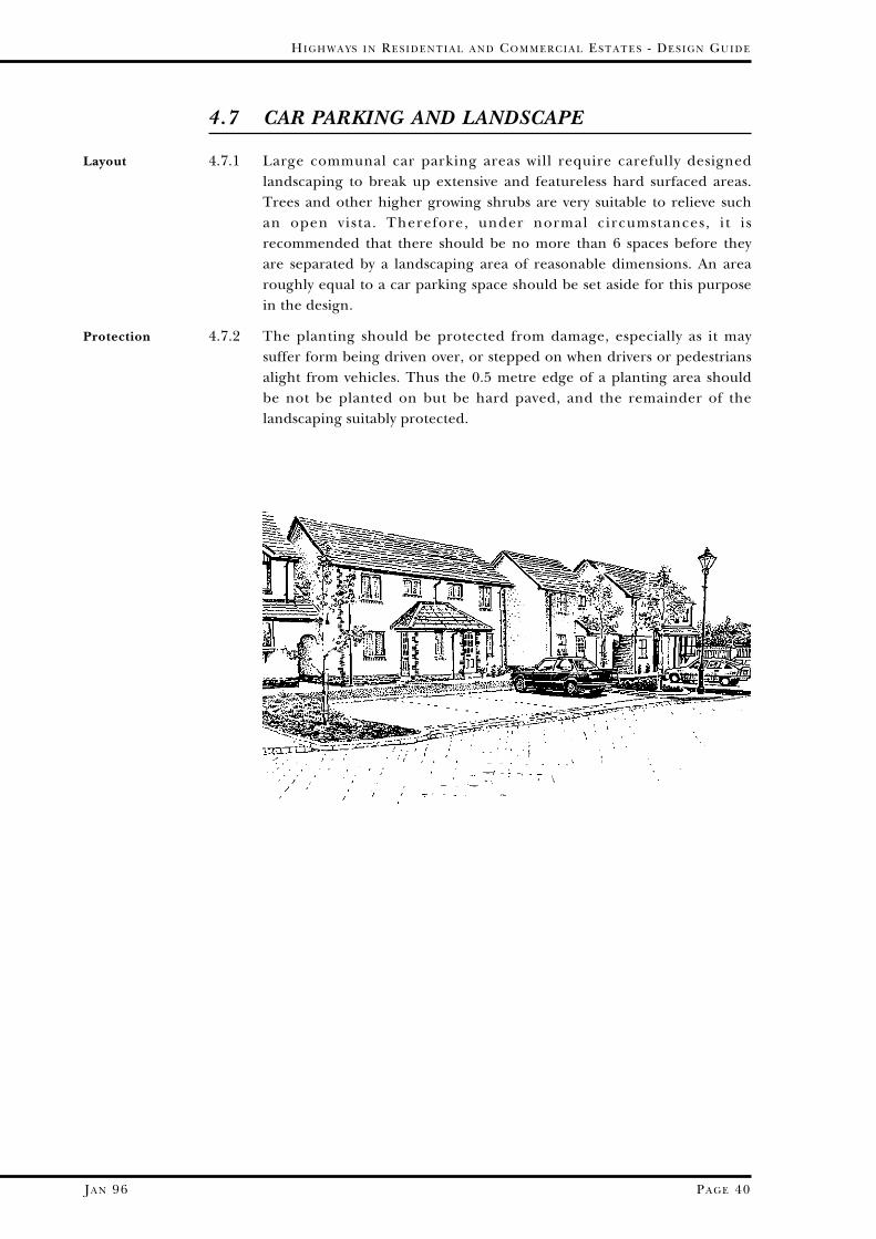
4.7.1 Large communal car parking areas will require carefully designedlandscaping to break up extensive and featureless hard surfaced areas.Trees and other higher growing shrubs are very suitable to relieve suchan open vista. Therefore, under normal circumstances, i t isrecommended that there should be no more than 6 spaces before theyare separated by a landscaping area of reasonable dimensions. An arearoughly equal to a car parking space should be set aside for this purposein the design.
4.7.2 The planting should be protected from damage, especially as it maysuffer form being driven over, or stepped on when drivers or pedestriansalight from vehicles. Thus the 0.5 metre edge of a planting area shouldbe not be planted on but be hard paved, and the remainder of thelandscaping suitably protected.
HI G H W A Y S I N RE S I D E N T I A L A N D CO M M E R C I A L ES T A T E S - DE S I G N GU I D E
PA G E 40JA N 96
Layout
Protection

JA N 96
5.2.2 Psychologically, long and wide perspectives encourage speed. Thegateway thus affords the first opportunity to foreshorten and narrow theperspective of the road ahead. When a narrowing and/or a horizontalshift is combined with a change in surface texture that gives both atangible and audible message, a gateway can be very effective in reducingspeeds at the entrance to the estate.
5.2.3 If the development is of such a size to require a Residential TransitionRoad (see Section 3.2), a gateway should be placed within its length. Itscharacter should reflect the function of that section of road, and beplaced at least 25 metres from the junction with the existing road.
5.2.4 The apparent width of the carriageway can be narrowed in a gateway byintroducing physical objects of sufficient dimensions at the immediateedge of the carriageway, and in some cases in a central island as well.Such physical objects could consist of raised planters, brick pillars, treesetc. However, care is to be exercised in ensuring that no pedestrianwishing to cross the road would be hidden by these features, or access orjunction visibility impaired.
HI G H W A Y S I N RE S I D E N T I A L A N D CO M M E R C I A L ES T A T E S - DE S I G N GU I D E
PA G E 42
How a Gateway
Can Be
Achieved
Function
5.2 GATEWAYS
5.2.1 A visitor entering the estate should first encounter a gateway. Themessage that the gateway should impart is that the driver is entering adifferent regime where speeds are lower, and that pedestrians, especiallychildren, may be moving within the highway.

JA N 96
PA R T ON E - HI G H W A Y S I N RE S I D E N T I A L ES T A T E S
PA G E 43
5.3 LAYOUT AND TRAFFIC CALMING
5.3.1 As indicated in Section 2.3, the estate road layout is to provide goodaccessibility while discouraging through traffic. This can be achieved bythe geometry of the layout itself, so that no journey can be undertakenwithout having to negotiate bends or junctions. Furthermore, in adevelopment of over 100 dwellings, there should be a choice of routes intoor out of the area. The layout would then be permeable, but at a slowspeed.
5.3.2 Traffic calming in association with junctions may often be an effectiveand economic method of achieving the required speed reduction. Forinstance, the geometry of the junction can serve to calm traffic where themain flow has to turn through a right angle. Alternatively, plateaux atjunctions may also be considered.
5.3.3 If footpaths and cycleways traverse the development, traffic calmingfeatures may well be appropriate where these cross roads. A footpath orcycleway may be part of an environmental ribbon, so the traffic calmingfeature should emphasise this green strip of land by appropriatelandscaping.
5.3.4 Traffic calming features may also be placed at points where the characterof the development changes, for instance where one form of housingchanges to another. Again, the nature of the calmer should be inharmony with the changing character.
5.3.5 Buildings themselves can be used to break up forward vistas. Garages, orhigh boundary walls, judiciously placed, can be a visual block and lead toa more human and interesting layout.
5.3.6 Speed reducing bends are also a useful means of calming traffic.
5.3.7 Thus, in overall layout terms, the estate roads should not be consideredas long roads with calming features introduced, but as short segments ofroad between calming features, integrally designed with the overalldevelopment.
Permeable at
Low Speed
Where
Footpaths,
Cycle Paths
Cross
How Calming
Features May
Be Introduced
SECTION 5
TRAFFIC CALMING
5.1 INTRODUCTION
5.1.1 High speed traffic is unacceptable within housing estates. Traffic speedsmust therefore be restrained in order to minimise the conflict betweenthe vehicle and pedestrian. It is the County Council’s intention that,wherever possible, it will seek a 20 mph speed limit for the whole area ofan estate, extending it where appropriate to surrounding residentialareas.
5.1.2 Physical constraints, as well as visual effects, are necessary to reducevehicle speeds. The imposition of a speed limit will not by itself ensurelower vehicle speeds, so physical measures must be incorporated to makeany 20 mph zone self-enforcing. Nor is speed reduction achieved bylessening visibility distances alone, but visibility requirements can bereduced as a consequence of the introduction of physical measures..
5.1.3 Any physical constraints introduced should ALWAYS take into accountaccess required by public service and emergency vehicles.
5.1.4 If an estate layout is to be successful in terms of convenience, accessibilityand safety, whilst also providing an attractive environment in which tolive, such speed control measures are fundamental to the design andshould therefore be considered as basic features of the estate.
PA R T ON E - HI G H W A Y S I N RE S I D E N T I A L ES T A T E S
PA G E 41 JA N 96
JA N 96
5.4.2 However, none of the above should be considered as “add-ons” to alayout; overall estate design should include several types of these calmingfeatures that fit comfortably in the overall environment.
5.4.3 The simplest and perhaps most obvious calming feature is the ramp atthe entrance to a shared surface access way; it combines (3), (7), (8) and(9) above. This has been well tried, and has found to be very successful.
5.4.4 Another calming feature that has been successful is the narrowing of thecarriageway to 3 metres, often combined with an informal pedestriancrossing in brick paviours and adjacent landscaping. This combines (6)and (7) above.
5.4.5 However, humps and other forms of vertical shift in carriageway aregenerally not acceptable in new highway layouts except at the entrance toShared Surface Access Ways. They are uncomfortable to ride over,especially for bus passengers, and can be noisy for adjacent residents.The exception to this is a plateau in a contrasting material, probablyconcrete block paviours, that covers the whole of the junction. Details ofplateaux and the legal requirements associated with them are given inparagraph 7.5.7.
5.4.6 Traffic calming can also be incorporated into junction design by givingthought to priorities.
5.4.7 Some suggestions for calming features are illustrated diagrammatically inSection 7; these are not to be considered a “menu” list to choose from,but to illustrate how the above principles are applied in practice. Itshould be noted how landscaping - both soft and hard - should be madean integral part of each suggestion. Other advice is contained in DevonCounty Council’s publication “Traffic Calming Guidelines”.
5.4.8 Narrowings will need maintenance at some time in their life. Therefore,thought should be given to where they are within a development so thatif and when repairs prove necessary, areas are not cut off from theremainder of the network. Loop roads rather than culs de sac are oneobvious solution, but even in culs de sac it may be possible to devise acalming device that permits over-running in such emergency situations,or later planned maintenance.
HI G H W A Y S I N RE S I D E N T I A L A N D CO M M E R C I A L ES T A T E S - DE S I G N GU I D E
PA G E 44
Integral With
Design
Types of
Traffic
Calming
Feature(1) by speed zone sign (2) by gateways (3) by turning traffic through a right angle at junctions or bends (4) by a lateral shift in the carriageway (5) by roundabouts or central islands (6) by narrowing the carriageway (7) by change in surface texture (8) by shared surface roads (9) by vertical shift in the carriageway.
5.4 THE TRAFFIC CALMING FEATURE IN DETAIL
5.4.1 Traffic calming features slow traffic down by a combination of some ofthe following methods:-
Narrowings and
Maintenance
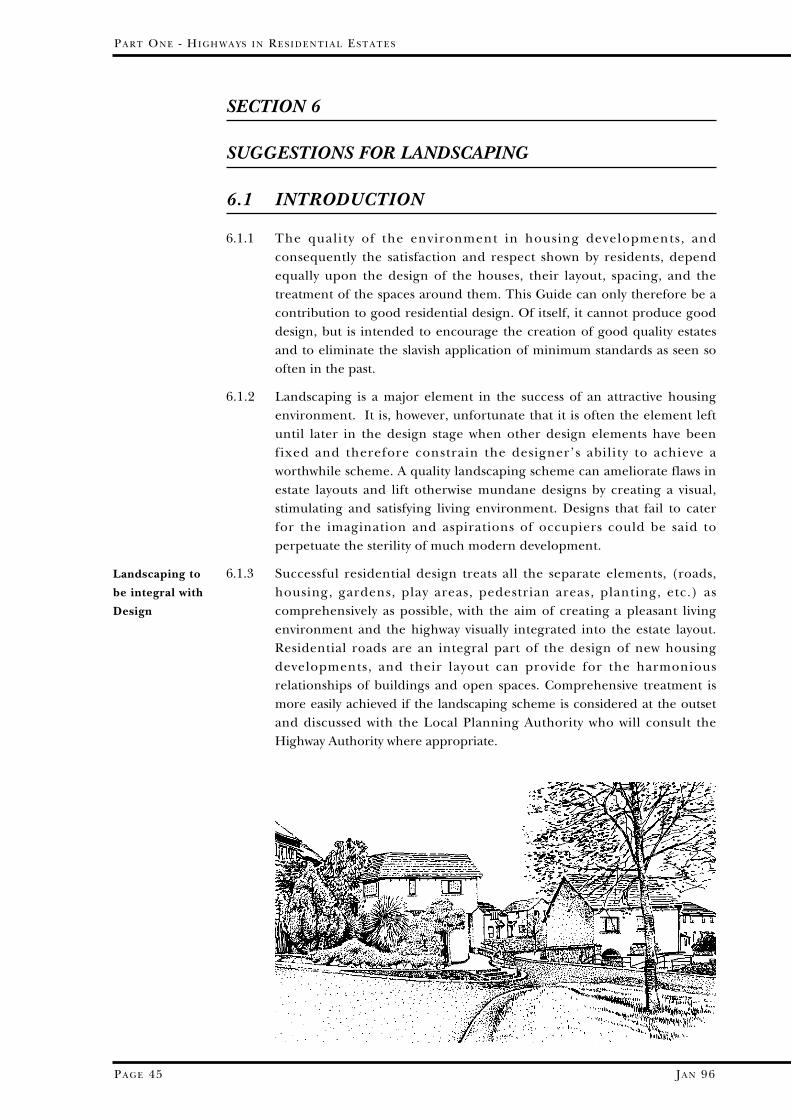
SECTION 6
SUGGESTIONS FOR LANDSCAPING
6.1 INTRODUCTION
6.1.1 The quality of the environment in housing developments, andconsequently the satisfaction and respect shown by residents, dependequally upon the design of the houses, their layout, spacing, and thetreatment of the spaces around them. This Guide can only therefore be acontribution to good residential design. Of itself, it cannot produce gooddesign, but is intended to encourage the creation of good quality estatesand to eliminate the slavish application of minimum standards as seen sooften in the past.
6.1.2 Landscaping is a major element in the success of an attractive housingenvironment. It is, however, unfortunate that it is often the element leftuntil later in the design stage when other design elements have beenfixed and therefore constrain the designer’s ability to achieve aworthwhile scheme. A quality landscaping scheme can ameliorate flaws inestate layouts and lift otherwise mundane designs by creating a visual,stimulating and satisfying living environment. Designs that fail to caterfor the imagination and aspirations of occupiers could be said toperpetuate the sterility of much modern development.
6.1.3 Successful residential design treats all the separate elements, (roads,housing, gardens, play areas, pedestrian areas, planting, etc.) ascomprehensively as possible, with the aim of creating a pleasant livingenvironment and the highway visually integrated into the estate layout.Residential roads are an integral part of the design of new housingdevelopments, and their layout can provide for the harmoniousrelationships of buildings and open spaces. Comprehensive treatment ismore easily achieved if the landscaping scheme is considered at the outsetand discussed with the Local Planning Authority who will consult theHighway Authority where appropriate.
PA R T ON E - HI G H W A Y S I N RE S I D E N T I A L ES T A T E S
PA G E 45 JA N 96
Landscaping to
be integral with
Design
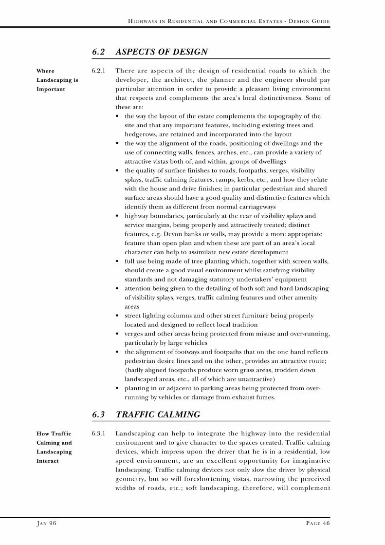
6.2 ASPECTS OF DESIGN
6.2.1 There are aspects of the design of residential roads to which thedeveloper, the architect, the planner and the engineer should payparticular attention in order to provide a pleasant living environmentthat respects and complements the area’s local distinctiveness. Some ofthese are: • the way the layout of the estate complements the topography of the
site and that any important features, including existing trees andhedgerows, are retained and incorporated into the layout
• the way the alignment of the roads, positioning of dwellings and theuse of connecting walls, fences, arches, etc., can provide a variety ofattractive vistas both of, and within, groups of dwellings
• the quality of surface finishes to roads, footpaths, verges, visibilitysplays, traffic calming features, ramps, kerbs, etc., and how they relatewith the house and drive finishes; in particular pedestrian and sharedsurface areas should have a good quality and distinctive features whichidentify them as different from normal carriageways
• highway boundaries, particularly at the rear of visibility splays andservice margins, being properly and attractively treated; distinctfeatures, e.g. Devon banks or walls, may provide a more appropriatefeature than open plan and when these are part of an area’s localcharacter can help to assimilate new estate development
• full use being made of tree planting which, together with screen walls,should create a good visual environment whilst satisfying visibilitystandards and not damaging statutory undertakers’ equipment
• attention being given to the detailing of both soft and hard landscapingof visibility splays, verges, traffic calming features and other amenityareas
• street lighting columns and other street furniture being properlylocated and designed to reflect local tradition
• verges and other areas being protected from misuse and over-running,particularly by large vehicles
• the alignment of footways and footpaths that on the one hand reflectspedestrian desire lines and on the other, provides an attractive route;(badly aligned footpaths produce worn grass areas, trodden downlandscaped areas, etc., all of which are unattractive)
• planting in or adjacent to parking areas being protected from over-running by vehicles or damage from exhaust fumes.
6.3 TRAFFIC CALMING
6.3.1 Landscaping can help to integrate the highway into the residentialenvironment and to give character to the spaces created. Traffic calmingdevices, which impress upon the driver that he is in a residential, lowspeed environment, are an excellent opportunity for imaginativelandscaping. Traffic calming devices not only slow the driver by physicalgeometry, but so will foreshortening vistas, narrowing the perceivedwidths of roads, etc.; soft landscaping, therefore, will complement
HI G H W A Y S I N RE S I D E N T I A L A N D CO M M E R C I A L ES T A T E S - DE S I G N GU I D E
PA G E 46JA N 96
Where
Landscaping is
Important
How Traffic
Calming and
Landscaping
Interact
physical changes in geometry. Existing features, for example retainedhedgebanks, could be the location of a calming feature. If as much of thehedgebank is retained as possible, together with new and complementaryplanting, the highway layout will be assimilated more easily into theoverall development scheme. The landscaping of a housing estate istherefore of concern to the Highway Authority as well as the LocalPlanning Authority, and the Highway Authority will encourage theincorporation of such features in a layout.
PA R T ON E - HI G H W A Y S I N RE S I D E N T I A L ES T A T E S
PA G E 47 JA N 96
6.4 MATERIALS AND FINISHES
6.4.1 The Local Planning Authority will undoubtedly expect residential roads anddetails of surface finishes, materials and landscaping to be locally distinctivein harmony with the character of the area. A different type of treatment willbe required according to the circumstances of each case. Natural rather thanartificial materials are to be preferred in particularly sensitive areas andwherever possible in other areas. In Conservation Areas and in villages withspecial character the following may be considered:-• an artificial stone equivalent rather than the standard concrete kerbs • flagged footways rather than tarmac • columns and street signs • concrete or brick paviours and matching kerbs • special bituminous materials and surface treatment which are user
friendly and attractive for the residents.
6.4.2 The treatment of visibility splays at the entrance to small developments inexisting village streets or rural lanes needs particular attention by perhapsusing walls or hedgebanks to match the surrounding area. In such areas,only the minimum size of visibility splay, consistent with adequate roadsafety, will be required. Fuller guidance on how a new road can beassimilated into a village or historic town is given in Section 2.9.
Visibility Splays
Materials
Chosen with
Care

6.4.3 In tightly knit urban developments it is probably more appropriate to relymainly on high quality, hard landscape finishes, with discreet treeplanting and landscaping in carefully chosen key locations. This may alsobe the case for prominently located small developments in tightlydeveloped rural Conservation Areas if this follows the existing layout. Inother rural areas, a softer, less ordered approach to design is more likelyto be appropriate and planting should be less formal in order to fit inwith the surroundings. Particular care will be required in National Parks,Areas of Outstanding Natural Beauty and Areas of Great LandscapeValue. The important thing is to analyse the characteristics of the areaand ensure that the layout harmonises with it.
6.4.4 There is now available an attractive variety of materials for the surfacingof roads and footpaths, including a range of block paviours and pavingslabs of varying dimensions and textures. Used sensitively, these will addto the character of the estate respecting the area’s local identity andemphasising the sense of local distinctiveness.
6.4.5 The character of development can be greatly enhanced by the retentionof existing trees, hedgerows, banks, fences and stone walls, whereverpossible. However, it is essential that the existing features should beincorporated into the design rather than retained in isolation.
HI G H W A Y S I N RE S I D E N T I A L A N D CO M M E R C I A L ES T A T E S - DE S I G N GU I D E
PA G E 48JA N 96
Hard and Soft
Finishes
Retention of
Existing
Features
Responsibility
for
Maintenance
6.5 MAINTENANCE
6.5.1 Securing and maintaining adequate management of landscaping mayeasily be overlooked during the planning process, which can lead toconfusion over responsibility for maintenance. It should be discussedand agreed with the Highway and Planning Authorities prior toimplementation. As a commuted sum may well be required forlandscaping within the adoptable highway, such landscaping should bedesigned to avoid high maintenance costs. Shrubs, including groundcover shrubs, may be cheaper to maintain than close mown turf. Ground

PA R T ON E - HI G H W A Y S I N RE S I D E N T I A L ES T A T E S
PA G E 49 JA N 96
cover may be used in visibility splays but care should be taken to ensurethat when fully grown it does not exceed 0.6 metres above channel levelso that pedestrians may readily be seen at junctions.
6.6 PLANTING
6.6.1 In the past, it has been the practice to adopt areas of planting only withinthe basic limit of the highway; however, planting outside these areas willnow be adopted if the areas are associated with the highway, subject tothe negotiation of a commuted sum for ongoing maintenanceresponsibility. In many instances, though, it would be desirable to includeplanting areas within the ownership of particular properties sinceexperience has shown that most private owners will take greater care ofsuch schemes. As previously stated, the layout should avoid creatingleftover spaces, but where highway geometry creates an area of plantingthat cannot sensibly be incorporated into adjoining public open space orprivate gardens, the responsibility of maintenance should be discussedwith the Planning and Highway Authorities at the outset.
6.6.2 Trees, where permitted in verges and visibility splays, should have clearstem for the first 2.0m of height to allow visibility underneath the crown.Where services exist in the verges of shared surface roads, grass cover ismost appropriate so that access to statutory undertakers’ equipment ispossible; nonetheless, some low planting may not be inappropriate insome cases, providing there is no risk of damage to the services beneath.
6.6.3 However, the landscaping of a new estate is more important to itsappearance than the ease with which services are installed andmaintained and service routes should therefore be designed to avoiddamage to the landscaping scheme. The types of trees and shrubs mustbe agreed beforehand with the Local Planning Authority in consultationwith the Highway Authority. The effect on the road structure should beconsidered when designing landscape planting adjacent to service stripsto minimise the possibility of root damage.
6.6.4 In selecting trees and shrubs to be incorporated into estates, theemployment of the professional expertise of a landscape architect is likely topay for itself, not least in the saving of much valuable time, and as individualcircumstances vary greatly within the County and between urban and rurallocations. A schedule of trees and shrubs that might be suitable in differentlocations is included for general guidance in Part 4 of this Guide, Appendix4C.
Landscape
Architect
Trees
Services
What Will Be
Adopted

JA N 96
HI G H W A Y S I N RE S I D E N T I A L A N D CO M M E R C I A L ES T A T E S - DE S I G N GU I D E
PA G E 50
SECTION 7
TECHNICAL DETAILS
7.1 INTRODUCTION
7.1.1 In this Section there are a number of drawings and diagrams illustrativeof the necessary dimensions for roads, footpaths, visibility splays, etc.Provided these dimensions are met as a minimum, the layouts should notbe slavishly followed. The introduction of variations in width, alignment,etc., as a design feature, consistent with the minimum standardsindicated, can result in pleasing and attractive layouts. Layouts that areslightly in excess of what is required will be adopted • for landscaping purposes (see Section 6) • if a more interesting layout results.
Such flexibility in the application of these standards, however, is notacceptable at the expense of safety.
7.1.2 Many of the requirements of residential estate roads are given in Table7.1.2 following this page. These are expanded in the followingparagraphs, tables and diagrams.
Summary of
Requirements
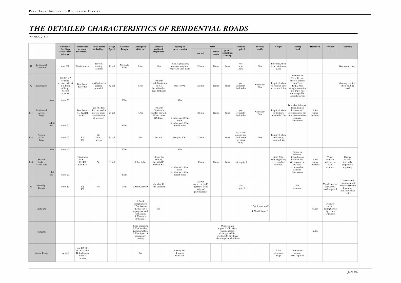
PA R T ON E - HI G H W A Y S I N RE S I D E N T I A L ES T A T E S
JA N 96
Number of Permissible Direct access Design Maximum Carriageway Junction Spacing of Kerbs Footways Footway Verges Turning Headroom Surface EntranceDwellings as minor to dwellings Speed Length width (m) radii with speed restraint pram/ required width Head
accessed via road from.... Major Roadnormal
vehicle pedestrianthis road access crossing
Yes with 100m, if geography yes If desired, then R1 Residential over 300 Distributor etc turning 40 kph Normally 5.5 m 10m requires length to 125mm 12mm 6mm both 2.0m to be minimum Gateway necessaryTransition facilities 100m be greater than 100m sides 2.0m
Required in 100-300 if 2 Type R2 road
or more 10m with where it extends accesses; 50-100 Yes if off street Local Distributor yes, Required when into Type Gateway required
R2 Access Road if in formDistributor
parking 32 kph 5.5 m or R1; 60m to 80m 125mm 12mm 6mm generally Generally no footway then R32 & R33; if off existingof loop;
R1 or R2provided 6m with other both sides 2.0m to be min 2.0m straight extension road
30-50 if Type R2 Roads into Type R33 cul de sac not acceptable
without gateway.
loop up to 50 300m 40m
Formal or informalYes (the fact 10m with depending on
Traditional Distributor that the road is Distributor yes, Required when location and 4.5mR31 Access R1, R2, R31 narrow needs 24 kph 4.8m and R1; 6m with 125mm 12mm 6mm generally Generally no footway; circumstances: but under
Ways or R32 careful design R2 and other both sides 2.0m min width 2.0m must accommodate archwaysof accesses) R3 Roads If cul de sac < 60m, standard
none dimensionscul de If cul de sac > 60m,
sac up to 30 150m at mid point
yes, at leastNarrow No on one side Required when
R32 Access up to 50 R2 direct 24 kph 3m 6m min See para 3.5.1 125mm 6mm (with verge 2.0m no footway;Ways R31 access on other min width 2m
side)
loop up to 50 300m 40mFormal orinformal
(Distributor 10m or 6m width 2.0m, depending on Visual ChangeShared or R1) with R1, min length 3m; location and 4.5m contrast of road
R33 Surface R2, R31 Yes 24 kph 4.8m - 6.0m 6m with R2, 40mm 12mm 6mm not required verge markers circumstances: under with access type to beAccess Way R32, R33 4m with R31 required. but must archways road emphasised
If cul de sac < 60m, accommodate required e.g. rampnone standard
cul de If cul de sac < 60m, dimensionssac up to 25 100m at mid point
Gateway and125mm ramp required;6m with R2 on access itself; Visual contrast entrance shouldR4 Housing up to 10 R2 Yes 25m 4.8m/6.0m with 4m with R31 12mm at front Not Not with access discourageCourts R31 edge of required required road required non-residentialparking space traffic
2.5m if unsegregated; Cycleway1.5m footway 1.5m if ‘unbound’ to be
Cycleways +1.5m c’way if 3m 2.75m distinguishedsegregated and 1.75m if ‘bound’ by colour
‘unbound’; or texture1.75m eachif ‘bound’.
2.0m normally; Other points:1.35m low flow; approval of barriers,2.5m high flow; passing places, 2.4mFootpaths2.75m if part of drainage, well-lit,
emergency overlook by dwellingsaccess; discourage non-local use
from R2, R31,and R33; from Passing bays 1.0m Communal
Private Drives up to 3 R1 if adequate 3m if longer clearance turninginternal than 25m strip head requiredturning
THE DETAILED CHARACTERISTICS OF RESIDENTIAL ROADSTABLE 7.1.2

HI G H W A Y S I N RE S I D E N T I A L A N D CO M M E R C I A L ES T A T E S - DE S I G N GU I D E
JA N 96
THE DETAILED CHARACTERISTICS OFRESIDENTIAL ROADSTABLE 7.1.2
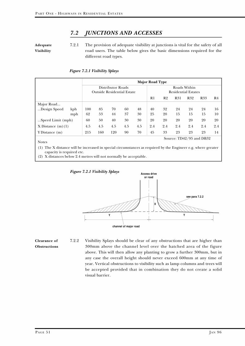
JA N 96
PA R T ON E - HI G H W A Y S I N RE S I D E N T I A L ES T A T E S
PA G E 51
7.2.2 Visibility Splays should be clear of any obstructions that are higher than300mm above the channel level over the hatched area of the figureabove. This will then allow any planting to grow a further 300mm, but inany case the overall height should never exceed 600mm at any time ofyear. Vertical obstructions to visibility such as lamp columns and trees willbe accepted provided that in combination they do not create a solidvisual barrier.
7.2 JUNCTIONS AND ACCESSES
7.2.1 The provision of adequate visibility at junctions is vital for the safety of allroad users. The table below gives the basic dimensions required for thedifferent road types.
Adequate
Visibility
Major Road Type
Distributor Roads Roads WithinOutside Residential Estate Residential Estates
R1 R2 R31 R32 R33 R4
Major Road......Design Speed kph 100 85 70 60 48 40 32 24 24 24 16
mph 62 53 44 37 30 25 20 15 15 15 10
...Speed Limit (mph) 60 50 40 30 30 20 20 20 20 20 20
X Distance (m)(1) 4.5 4.5 4.5 4.5 4.5 2.4 2.4 2.4 2.4 2.4 2.4
Y Distance (m) 215 160 120 90 70 45 33 23 23 23 14
Source: TD42/95 and DB32Notes
(1) The X distance will be increased in special circumstances as required by the Engineer e.g. where greatercapacity is required etc.
(2) X distances below 2.4 metres will not normally be acceptable.
Access driveor road
Y Y
X
channel of major road
see para 7.2.2
Figure 7.2.1 Visibility Splays
Clearance of
Obstructions
Figure 7.2.1 Visibility Splays

JA N 96
HI G H W A Y S I N RE S I D E N T I A L A N D CO M M E R C I A L ES T A T E S - DE S I G N GU I D E
PA G E 52
7.2.3 The minimum spacing between junctions should be as follows:
Table 7.2.3 Minimum Spacing of Junctions
Junction Types
II
II*
V**
***
indicates that the type of junction is permitted
indicates the drawing on the following pages thatshows the recommended layout
these combinations are permitted only in certaincircumstances
indicates that private accesses are permitted;
a private access is only permitted off these roads ifthere are full turning facilities within the curtilageof the dwelling
this junction layout is only acceptable in specialcircumstances, and also when the number ofhouses on the shared surface road is 8 or less
On distributor roads On residential roads
Junctions on same side of road 90m 35mJunctions on opposite side of road 40m 15m
[Measurements are centre line to centre line]
Minimum
Spacing
between
Junctions
7.2.4 The following table shows the junction combination permitted, and thediagrams on the subsequent pages illustrate the appropriate layout:-
Table 7.2.4 Types of Junction
if Minor Road is
R1 R2 R31 R32 R33 R4 Cycle Private
if Major Road is Way Access
Local Distributor I I I II* III VIII
R1 Residential Transition I I II* III VIII ***
R2 Access Road I I II IV IV VIII
R31 Trad. Access Way I II IV, V** IV VIII
R32 Narrow Access Way VI VI VIII
R33 Shared Surface VII IX
Village Street I I V** ***
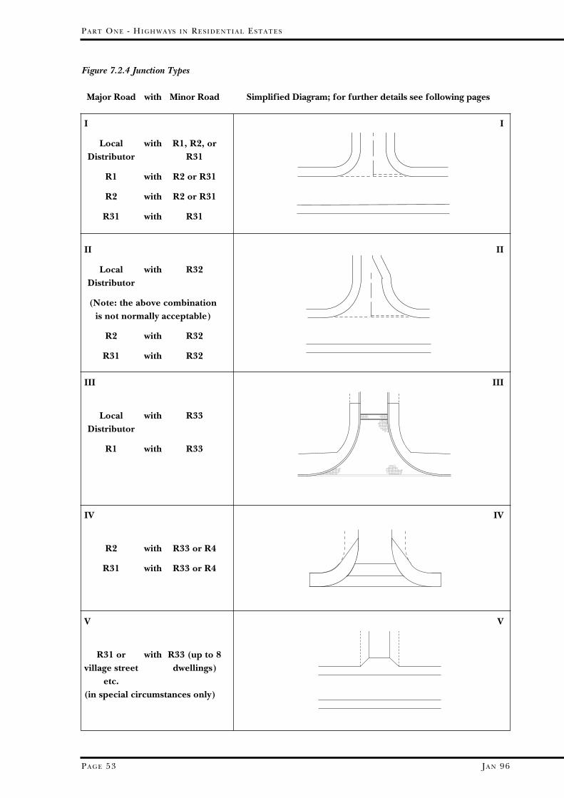
JA N 96
V V
R31 or with R33 (up to 8village street dwellings)
etc.(in special circumstances only)
PA R T ON E - HI G H W A Y S I N RE S I D E N T I A L ES T A T E S
PA G E 53
Major Road with Minor Road Simplified Diagram; for further details see following pages
III III
Local with R33 Distributor
R1 with R33
II II
Local with R32Distributor
(Note: the above combinationis not normally acceptable)
R2 with R32
R31 with R32
IV IV
R2 with R33 or R4
R31 with R33 or R4
I I
Local with R1, R2, or Distributor R31
R1 with R2 or R31
R2 with R2 or R31
R31 with R31
Figure 7.2.4 Junction Types
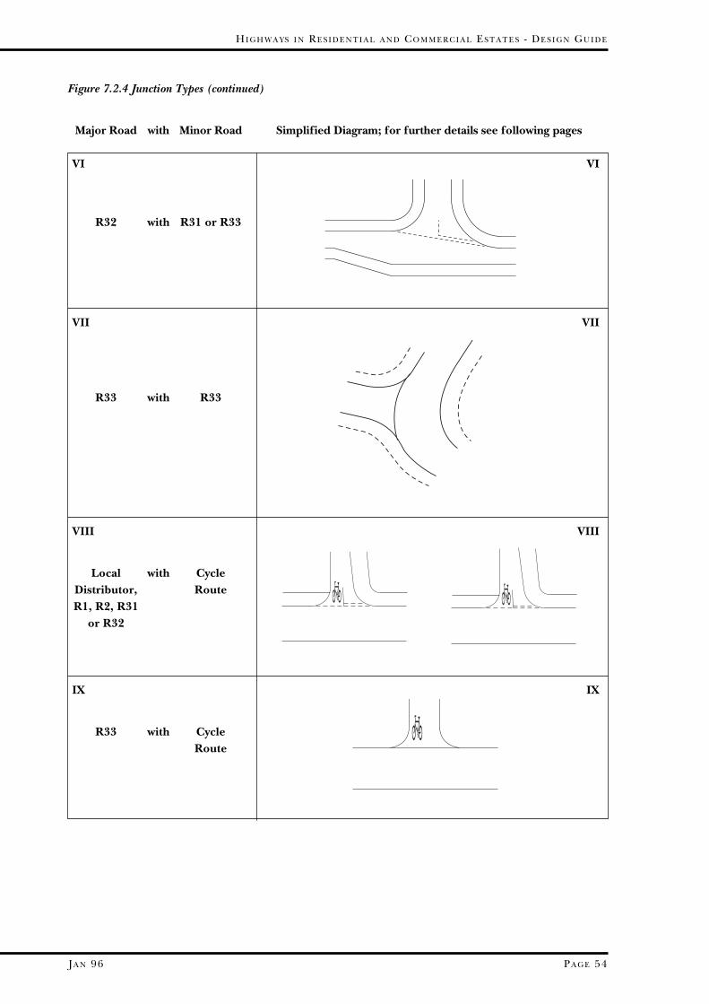
JA N 96
HI G H W A Y S I N RE S I D E N T I A L A N D CO M M E R C I A L ES T A T E S - DE S I G N GU I D E
PA G E 54
Major Road with Minor Road Simplified Diagram; for further details see following pages
VII VII
R33 with R33
VI VI
R32 with R31 or R33
Figure 7.2.4 Junction Types (continued)
VIII VIII
Local with Cycle Distributor, RouteR1, R2, R31
or R32
IX IX
R33 with CycleRoute
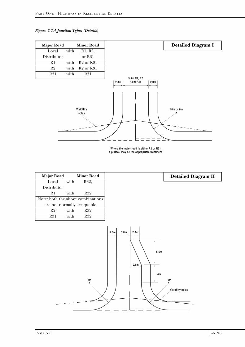
JA N 96
PA R T ON E - HI G H W A Y S I N RE S I D E N T I A L ES T A T E S
PA G E 55
Figure 7.2.4 Junction Types (Details)
Major Road Minor RoadLocal with R32,
DistributorR1 with R32
Note: both the above combinationsare not normally acceptable
R2 with R32R31 with R32
Detailed Diagram IMajor Road Minor RoadLocal with R1, R2,
Distributor or R31R1 with R2 or R31R2 with R2 or R31
R31 with R315.5m R1, R2
4.8m R312.0m
10m or 6m
2.0m
Visibilitysplay
Where the major road is either R2 or R31a plateau may be the appropriate treatment
6m
3.0m 2.0m
5.5m
6m
Visibility splay
2.0m
2.5m
4m
Detailed Diagram II

JA N 96
HI G H W A Y S I N RE S I D E N T I A L A N D CO M M E R C I A L ES T A T E S - DE S I G N GU I D E
PA G E 56
Figure 7.2.4 Junction Types (Details)
G G
GG
G G
4.8m 1.8m
2.0m
2.0m 2.0m10m R
or6m R
3
4
1
visibility splay visibility splay
footway
Tactile paving
Tactile paving
verge
These gullies to beprovided where side
road falls towardmain road These gullies to be
provided where sideroad falls away from main road
Gullies to be provided at tangent points, but so placed as not to conflict with a
pedestrian crossing point
A
A
10m Ror
6m R
DROPPINGKERB
DROPPED KERBfor footway crossing
RAMPformed from stone
setts or similar0.9m 2.0m 1.4m
6mm upstand
8%
125mm upstand
6mm upstand
125mmupstand (R4)
40mmupstand (R33)
6mm upstand
125mm upstand
carriagewaysurface
APRONformed from rectangular concrete block paviours
4m 6m or 10m
Top of kerbs
carriagewaysurface
SECTION A-A
Notes:apron to be formed from a visually and texturally distinctive surface from the major road (see para 2.4.2)
kerbs to be precast concrete or other approved to match adjacent kerbing
ramp to be stone setts, or similar approved, on a C20P concrete bed and 25mm Ronafix or similarly approved mortar; the spacing between setts is to be 6mm and the mortar 6mm below the top of the setts; the gradient is to be relative to the long fall of the adjacent kerbs
carriageway to be visually and texturally distinctive from the major road (see para 2.4.2)
14
22
3
4
3
2
1
Detailed Diagram IIIMajor Road Minor RoadLocal with R33
DistributorR1 with R33

JA N 96
PA R T ON E - HI G H W A Y S I N RE S I D E N T I A L ES T A T E S
PA G E 57
Major Road Minor RoadR2 with R33 or R4
R31 with R33 or R4
G G
G G
6mm upstand
1.4m @ 8%
2m @ 2.5%
4m or 6m radius
G = Gully
125mm or 40mm kerb face
Tactile paving
Verge or footway according to road typeThese two gullies are to be
provided where side roadfalls toward the major road
Bituminous surface
Bituminous Surface
B
B
Gullies to be provided at tangentpoints, but so placed as not to conflict with a pedestrian crossing point
1
3
4
DROPPINGKERB
DROPPED KERBFOOTWAY CROSSING
RAMPformed from stone setts
or similar
0.9m 2.0m 1.4m
crossing formed in DBM material
6mm upstand
8%
125mm upstand
6mm upstand
no upstand for kerb
125mmupstand (R4)
40mmupstand (R33)
SECTION B-B
Notes:
footway crossing to be formed in DBM material as per the specification for Type R31 or R4 roads; it is to have a crossfall of 2.5%, the directionof which depends upon the direction of the fall of the side road; however, the 6mm kerb upstand is to remain constant.
kerbs to be precast concrete or other approved to match adjacent kerbing.
ramp to be visually and texturally distinctive from the major road (see para 2.4.2); the gradient is to be relative to the long fall of the adjacent kerbs
carriageway to be visually and texturally distinctive from the major road (see para 2.4.2).
1
2
2 2
3
4
1
23
4
Figure 7.2.4 Junction Types (Details) (continued)
Detailed Diagram IV

JA N 96
HI G H W A Y S I N RE S I D E N T I A L A N D CO M M E R C I A L ES T A T E S - DE S I G N GU I D E
PA G E 58
Figure 7.2.4 Junction Types (Details) (continued)
Droppedkerbs
with 6mm upstand
verge
Standard Visibility splay
verge
Kerbs for shared surface
roads
Contrastingmaterial
to footwayBitumen apron
Droppingkerb
Footway edging kerbsDropped kerb with
6mm upstand
4.8m
6.0m radius 9.0m radius
6m
3m
5.5m 11m
2m
2m
2m
The arrangement for R31/32 is shown;if minor road is R33 then the treatmentof the minor road is to be similar to diagram iii
Major Road Minor RoadR31 with R33
or village (up to 8street dwellings)
(in specialcircumstances
only)
Major Road Minor RoadR32 with R31 or R33
Detailed Diagram V
Detailed Diagram VI

JA N 96
PA R T ON E - HI G H W A Y S I N RE S I D E N T I A L ES T A T E S
PA G E 59
Figure 7.2.4 Junction Types (Details) (continued)
Priority at junction to be indicated by flush kerb to match kerbs at edge of carriageway
verge
Major Road Minor RoadR33 with R33
3m radius
preformedcycle logoto diag.1057
Shared Cycle/PedestrianRoute
2.5m
carriageway
3m radius
cycle lanewidenedfrom 1.5m to 2.5m overlast 6m
Segregated Cycle/PedestrianRoute
1.5m 1.5m
carriageway
Major Road Minor RoadLocal with Cycle Route
Distributor,R1, R2, R31
or R32
3m radius
bituminoussurface
preformedcycle logoto diag.1057
kerb flush withR33 road
Block paviours
2.5m
Major Road Minor RoadR33 with Cycle Route
Detailed Diagram VII
Detailed Diagram VIII
Detailed Diagram IX

JA N 96
HI G H W A Y S I N RE S I D E N T I A L A N D CO M M E R C I A L ES T A T E S - DE S I G N GU I D E
PA G E 60
7.3.3 The speed of vehicles around a bend will vary according to its radius. Inorder to assist in assessing the mean speed of vehicles travelling around abend of a given radius, the following table is included:
Table 7.3.3 Speed on Bends
7.3 CARRIAGEWAYS
7.3.1 Widths, lengths between traffic calming features, and minimumhorizontal radii are given in Table 7.1.2.
7.3.2 The forward visibility required as given below is the stopping distanceneeded by vehicles travelling along a road at the design speed.
Table 7.3.2 Forward Visibility
General
Forward
Visibility
Bend Radius(m) 10 15 20 25 30 35 40 45 50
Mean Speed(kph) 15 21 27 32 36 40 43 46 48
Mean Speed(mph) 9.5 13 16.5 20 22.5 25 26.5 28.5 30
Design Speed - kph 48 40 32 24 16 8- mph 30 25 20 15 10 5
Stopping Distance (m) 60 45 33 23 14 6
Speed on Bends
Forward
Visibility on
Bends
7.3.4 Forward visibility on bends is to be provided as follows:
Figure 7.3.4
stopping distance
2345678234
5
6
7
8
A1
B2
3
4
5
6
7
8
1
1
stoppingdistance
1.5m
1.5m
2
Shaded area to be kept clear ofobstruction above a height of 300mm.(see para. 7.2.2)
Note: Where summits of verticalcurves occur this height will needto be reduced

JA N 96
PA R T ON E - HI G H W A Y S I N RE S I D E N T I A L ES T A T E S
PA G E 61
7.3.5 At least the minimum visibility defined in Table 7.3.2 above should alwaysbe available to the driver at the design speed of the road. The envelopeof the area to be kept free of obstruction can be derived in the followingmanner:1. draw a line parallel to the inside kerb, 1.5m into the carriageway, to
represent the path of an approaching vehicle 2. obtain the design speed for the type of road from Table 7.1.2. The
required stopping distance for this design speed is given in 7.3.2above
3. measure the full stopping distance back from tangent point “A” aboveand divide the vehicle path into equal increments (say 3m), andnumbered
4. continue these increments sequentially around the curve until a fullstopping distance beyond tangent point “B” above is achieved
5. draw lines to connect increment points that are the stopping distanceapart; the resultant envelope is that which should be kept clear ofobstructions more than 600mm in height, as more fully described inparagraph 7.2.2.
Calculation of
Forward
Visibility
“Envelope”
Table 7.3.6Gradients and
Crossfalls
Carriageway CyclewayFootwayFootpath
Max Min Max Min Max
Longitudinal Gradient 10% 1% 3% 1% 8%(general) (note 1) (note 2) (note 3) (note 1)
Longitudinal gradientof side road at junction
5%(for first 6m from main road channel)
Crossfall 3.3% 2.5% 2.5%
(1) increased gradients will be considered provided they are discussedand agreed with the engineer at the planning application stagetogether with any special details (including surfacing) which may berequired.
(2) this gradient may be reduced to 0.67% if combined drainage andkerb blocks are used, except for block-paved roads.
(3) the gradient of cycleways may be increased to 5% for lengths up to100m, or 7% for lengths up to 30m.

JA N 96
HI G H W A Y S I N RE S I D E N T I A L A N D CO M M E R C I A L ES T A T E S - DE S I G N GU I D E
PA G E 62
7.3.8 Widening is required on bends when the sum of the swept paths ofpassing vehicles is greater than the width of the carriageway. It is betterto alter the inner radius of the bend when accommodating this widening.
7.3.9 The widening required will depend on the likelihood of various types ofvehicle meeting at or near the bend. The Engineer will indicate whichconflict will need to be accommodated; this depends on the layout of theestate, and whether the road will be used by buses etc. It will also dependon whether it is considered necessary to accommodate the conflict at allpoints on the road, namely in the bend itself; in some circumstances itmay be acceptable to consider that the one of the vehicles could waituntil the other had negotiated the bend. For example, in culs de sac, it isunlikely that more than a car/car conflict need be accommodated,whereas in spine roads a midibus/refuse vehicle conflict may need to beconsidered. The following table gives the required width of carriagewayfor bends of varying radii, together with the length over which thiswidening is to be applied.
7.3.7 The length of vertical curves required to accommodate various changesof gradient for various road types is as follows
Figure 7.3.7 Vertical Curves
Vertical Curves
TYPE R1 ROADS
TYPE R3 ROADS
TYPE R2 ROADS
Summit and Valley
Summit
Valley
Summit
Valley
0
10
20
40
30
50
60
70
80
90
100
5 10 15 20
change in gradient G%
m
G%
min
imum
leng
th (m
)
Widening on
Bends

JA N 96
PA R T ON E - HI G H W A Y S I N RE S I D E N T I A L ES T A T E S
PA G E 63
length over whichwidening is to take place
widening
Note: kerbline to belaid as a smooth curve
Note: all dimensions are in metres“over”= the distance over which widening is to take place as shown below
Table 7.3.9 Widening on bends
Figure 7.3.9 Length Over Which Widening is to be Applied
Car/Car Car/ Car/ Midibus/Refuse Midibus RefuseVehicle Vehicle
Radius width over width over width over width over
4.8 metre 10m 5.75 14 7.65 22 7.95 25carriageway 15m 7.15 27 7.25 30
20m 6.95 30 7.05 30 7.85 30
5.5 metre 10m 6.00 12 7.55 16 7.75 20carriageway 15m 7.15 19 7.35 22
20m 6.85 23 6.95 25 8.05 31
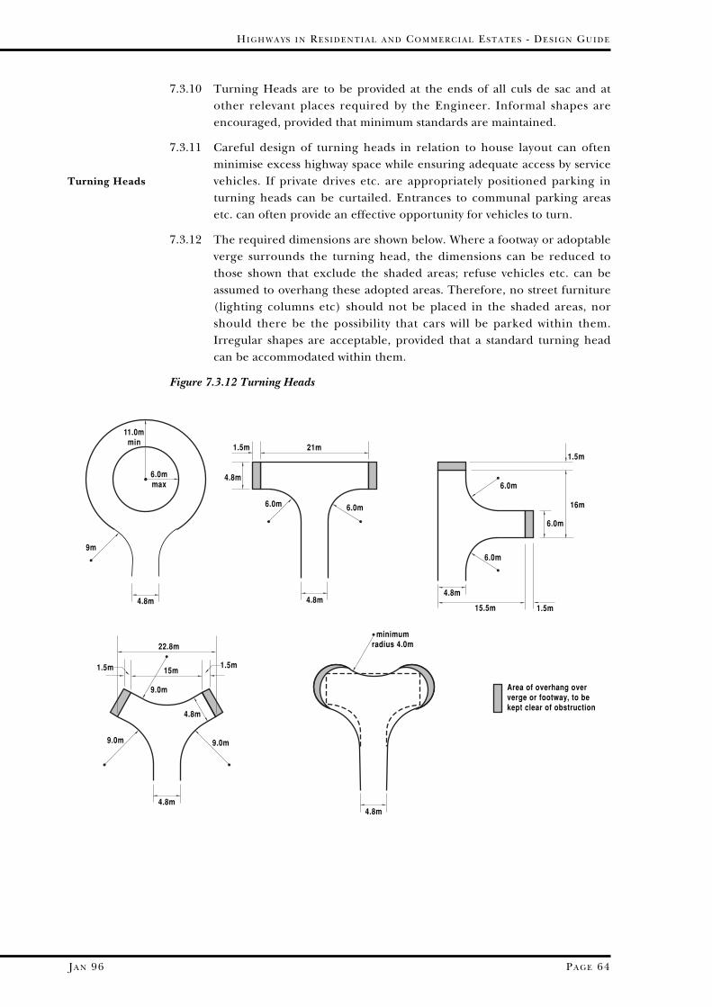
JA N 96
HI G H W A Y S I N RE S I D E N T I A L A N D CO M M E R C I A L ES T A T E S - DE S I G N GU I D E
PA G E 64
7.3.10 Turning Heads are to be provided at the ends of all culs de sac and atother relevant places required by the Engineer. Informal shapes areencouraged, provided that minimum standards are maintained.
7.3.11 Careful design of turning heads in relation to house layout can oftenminimise excess highway space while ensuring adequate access by servicevehicles. If private drives etc. are appropriately positioned parking inturning heads can be curtailed. Entrances to communal parking areasetc. can often provide an effective opportunity for vehicles to turn.
7.3.12 The required dimensions are shown below. Where a footway or adoptableverge surrounds the turning head, the dimensions can be reduced tothose shown that exclude the shaded areas; refuse vehicles etc. can beassumed to overhang these adopted areas. Therefore, no street furniture(lighting columns etc) should not be placed in the shaded areas, norshould there be the possibility that cars will be parked within them.Irregular shapes are acceptable, provided that a standard turning headcan be accommodated within them.
Figure 7.3.12 Turning Heads
Turning Heads
4.8m
6.0mmax
11.0mmin
9m
4.8m
4.8m4.8m
4.8m
15m
6.0m 6.0m
6.0m
6.0m
6.0m
16m
15.5m
9.0m 9.0m
minimumradius 4.0m
21m
9.0m
4.8m
1.5m1.5m
1.5m
1.5m1.5m
4.8m
Area of overhang oververge or footway, to be kept clear of obstruction
22.8m
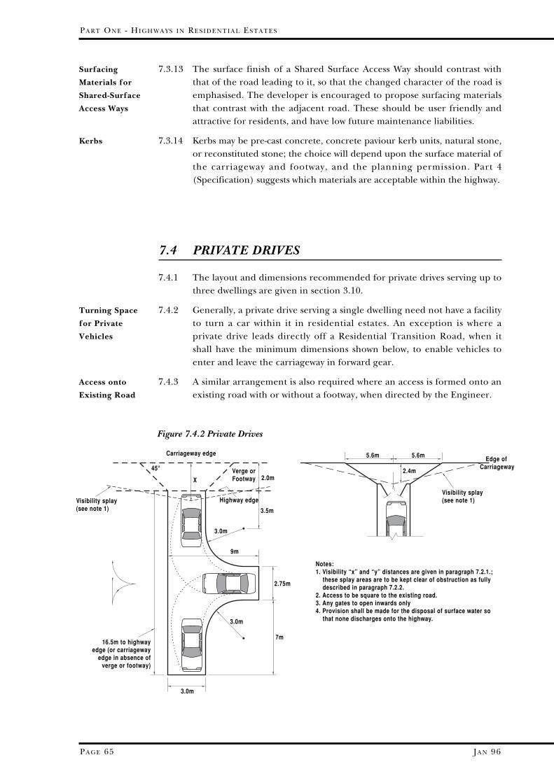
JA N 96
PA R T ON E - HI G H W A Y S I N RE S I D E N T I A L ES T A T E S
PA G E 65
Surfacing
Materials for
Shared-Surface
Access Ways
7.3.13 The surface finish of a Shared Surface Access Way should contrast withthat of the road leading to it, so that the changed character of the road isemphasised. The developer is encouraged to propose surfacing materialsthat contrast with the adjacent road. These should be user friendly andattractive for residents, and have low future maintenance liabilities.
7.3.14 Kerbs may be pre-cast concrete, concrete paviour kerb units, natural stone,or reconstituted stone; the choice will depend upon the surface material ofthe carriageway and footway, and the planning permission. Part 4(Specification) suggests which materials are acceptable within the highway.
7.4 PRIVATE DRIVES
7.4.1 The layout and dimensions recommended for private drives serving up tothree dwellings are given in section 3.10.
7.4.2 Generally, a private drive serving a single dwelling need not have a facilityto turn a car within it in residential estates. An exception is where aprivate drive leads directly off a Residential Transition Road, when itshall have the minimum dimensions shown below, to enable vehicles toenter and leave the carriageway in forward gear.
7.4.3 A similar arrangement is also required where an access is formed onto anexisting road with or without a footway, when directed by the Engineer.
Kerbs
Turning Space
for Private
Vehicles
Access onto
Existing Road
X 2.0mVerge orFootway
45°
3.0m
3.0m
2.75m
9m
3.0m
3.5m
Carriageway edge
Highway edgeVisibility splay(see note 1)
16.5m to highwayedge (or carriageway
edge in absence ofverge or footway)
7m
5.6m 5.6m
2.4m
Edge of Carriageway
Visibility splay(see note 1)
Notes:1. Visibility “x” and “y” distances are given in paragraph 7.2.1.; these splay areas are to be kept clear of obstruction as fully described in paragraph 7.2.2. 2. Access to be square to the existing road.3. Any gates to open inwards only4. Provision shall be made for the disposal of surface water so that none discharges onto the highway.
Figure 7.4.2 Private Drives
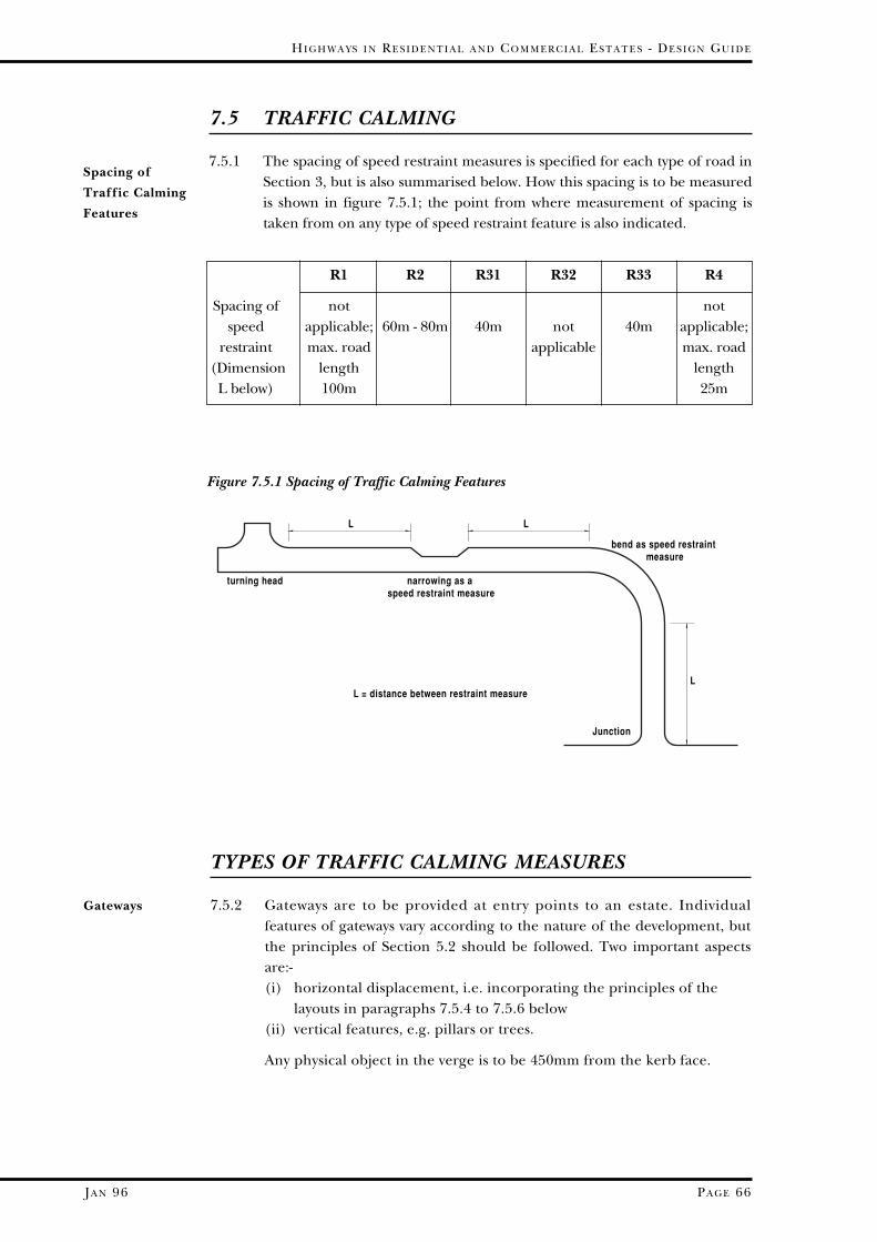
JA N 96
HI G H W A Y S I N RE S I D E N T I A L A N D CO M M E R C I A L ES T A T E S - DE S I G N GU I D E
PA G E 66
7.5 TRAFFIC CALMING
7.5.1 The spacing of speed restraint measures is specified for each type of road inSection 3, but is also summarised below. How this spacing is to be measuredis shown in figure 7.5.1; the point from where measurement of spacing istaken from on any type of speed restraint feature is also indicated.
Spacing of
Traffic Calming
Features
narrowing as a speed restraint measure
L L
LL = distance between restraint measure
turning head
bend as speed restraint measure
Junction
R1 R2 R31 R32 R33 R4
Spacing of not notspeed applicable; 60m - 80m 40m not 40m applicable;
restraint max. road applicable max. road(Dimension length lengthL below) 100m 25m
Figure 7.5.1 Spacing of Traffic Calming Features
Gateways
TYPES OF TRAFFIC CALMING MEASURES
7.5.2 Gateways are to be provided at entry points to an estate. Individualfeatures of gateways vary according to the nature of the development, butthe principles of Section 5.2 should be followed. Two important aspectsare:-(i) horizontal displacement, i.e. incorporating the principles of the
layouts in paragraphs 7.5.4 to 7.5.6 below (ii) vertical features, e.g. pillars or trees.
Any physical object in the verge is to be 450mm from the kerb face.

JA N 96
PA R T ON E - HI G H W A Y S I N RE S I D E N T I A L ES T A T E S
PA G E 67
7.5.3 A bend will adequately serve as a traffic calming device providing itconforms to the following dimensions:-
Figure 7.5.3 Speed Restricting Bends
Speed
Restricting
Bends
70°minimum
R = 20m (max)
spacing of speed restraint devicesto be measured from this point
7m12m 12m
3
2
1
3.5m
2.0m
3.5m35
12
3
Keep left bollardsStone setts or similarBlock pavioursOver-run area formed from setts raised 12mm aboveadjacent road surface. (see 7.5.10)
5
2
7.5.4 Horizontal displacement effectively calms traffic if it is not possible todrive ‘straight through’. The following are examples of how this can beaccomplished, the first two of which are suitable for 5.5m wide roads.The layout should be checked to see if a refuse lorry or pantechnicon cannegotiate it where junctions etc. are close to the calming device.
Figure 7.5.4 Horizontal Displacement
Calming by
Horizontal
Displacement
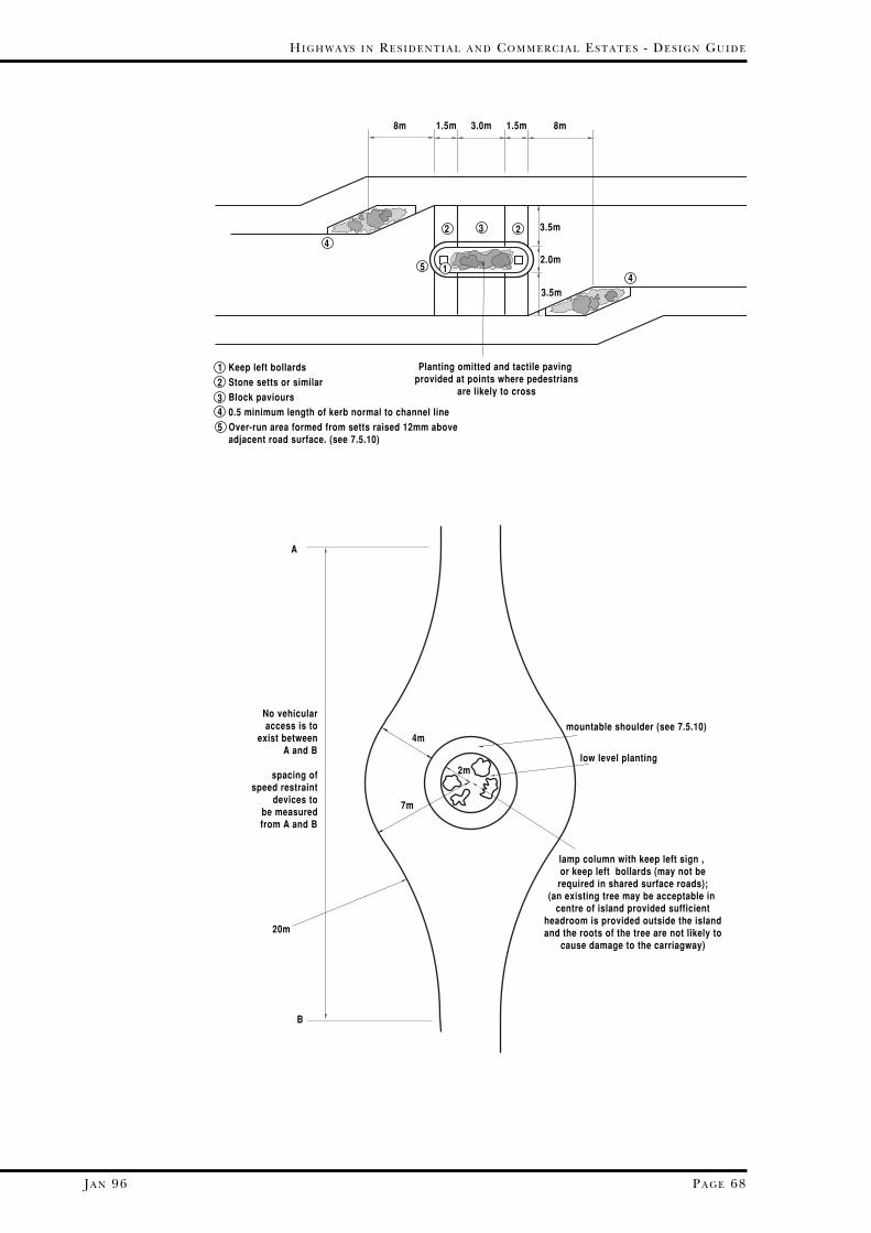
JA N 96
HI G H W A Y S I N RE S I D E N T I A L A N D CO M M E R C I A L ES T A T E S - DE S I G N GU I D E
PA G E 68
3.0m1.5m 1.5m
324
41
3.5m
2.0m
3.5m
Planting omitted and tactile paving provided at points where pedestrians
are likely to cross
12
34
Keep left bollardsStone setts or similarBlock paviours0.5 minimum length of kerb normal to channel lineOver-run area formed from setts raised 12mm aboveadjacent road surface. (see 7.5.10)
8m 8m
5
2
5
7m
4m
2m
mountable shoulder (see 7.5.10)
low level planting
lamp column with keep left sign , or keep left bollards (may not berequired in shared surface roads);
(an existing tree may be acceptable in centre of island provided sufficient
headroom is provided outside the islandand the roots of the tree are not likely to
cause damage to the carriagway)
20m
A
B
No vehicularaccess is to
exist betweenA and B
spacing ofspeed restraint
devices tobe measuredfrom A and B
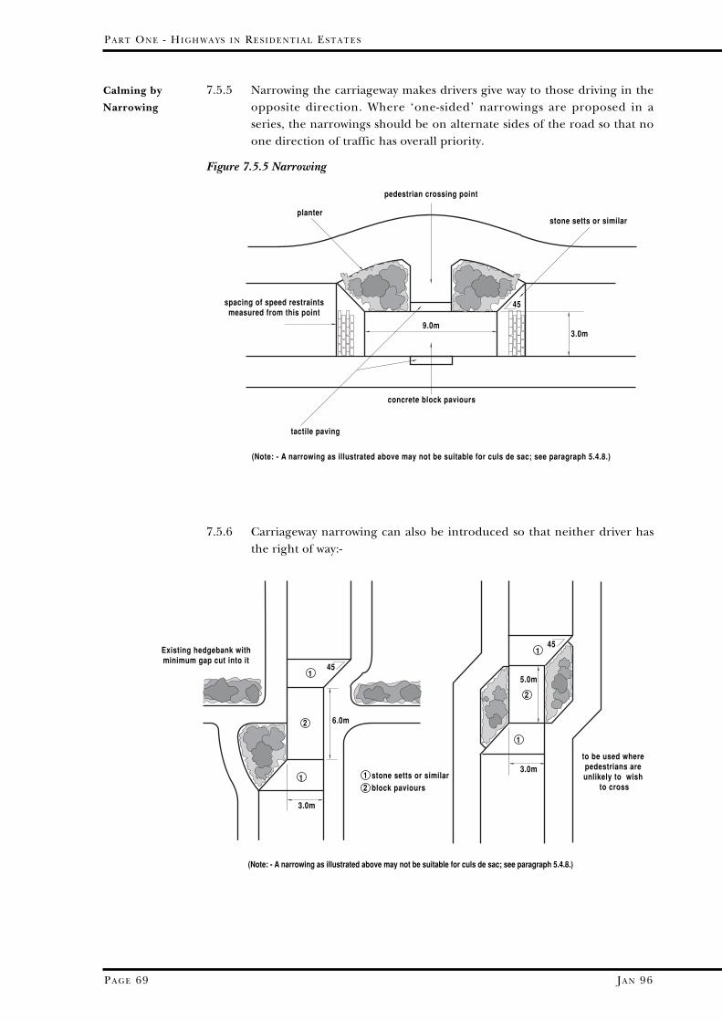
JA N 96
PA R T ON E - HI G H W A Y S I N RE S I D E N T I A L ES T A T E S
PA G E 69
7.5.5 Narrowing the carriageway makes drivers give way to those driving in theopposite direction. Where ‘one-sided’ narrowings are proposed in aseries, the narrowings should be on alternate sides of the road so that noone direction of traffic has overall priority.
Figure 7.5.5 Narrowing
Calming by
Narrowing
concrete block paviours
pedestrian crossing point
stone setts or similar
spacing of speed restraintsmeasured from this point
planter
(Note: - A narrowing as illustrated above may not be suitable for culs de sac; see paragraph 5.4.8.)
3.0m9.0m
45
tactile paving
Existing hedgebank withminimum gap cut into it
to be used where pedestrians are unlikely to wish
to cross1
1
1
1
2
2
stone setts or similarblock paviours
12
45
3.0m
6.0m
5.0m
45
3.0m
(Note: - A narrowing as illustrated above may not be suitable for culs de sac; see paragraph 5.4.8.)
7.5.6 Carriageway narrowing can also be introduced so that neither driver hasthe right of way:-

JA N 96
7.5.7 At some junctions, the whole area may be raised by 75mm in blockpaviours, as shown below. The Highways (Road Humps) Regulations 1990apply, so that such plateaux and other raised areas may only be usedunder certain conditions. For instance, all vehicular traffic approachingthe raised area will, within 40 metres of it, either have entered thehighway in which it is placed through a junction with another highway, orhave passed through a horizontal bend fitting the criteria of paragraph7.5.3 within 32 metres. The manner in which these dimensions aremeasured is as in paragraph 7.5.1. Although other speed reducingfeatures may be used after such a raised area, in order to comply with thespacing requirement of such features laid out elsewhere in this Guide,there must be no more than 150 metres to the next raised area. Trafficsigns may well be required to warn of the humps.
HI G H W A Y S I N RE S I D E N T I A L A N D CO M M E R C I A L ES T A T E S - DE S I G N GU I D E
PA G E 70
50mm kerbupstand
Block paviours
Tactile paving. Kerbs at pedestriancrossing point to have 6mm upstand
Ramp to be 1.0m long and have a rise(relative to kerb line) of 75mm
If the minor road is R33 or R4, whichwould otherwise have a ramp at the entrance, this ramp could be replacedby a horizontal strip 1.0m wide formedwith stone setts or similar
Point of measurement for spacing ofspeed restraint measures.
1
2
2
23
4
3
1
2
3
4
55
5
5
Calming at
Junctions by
Plateaux
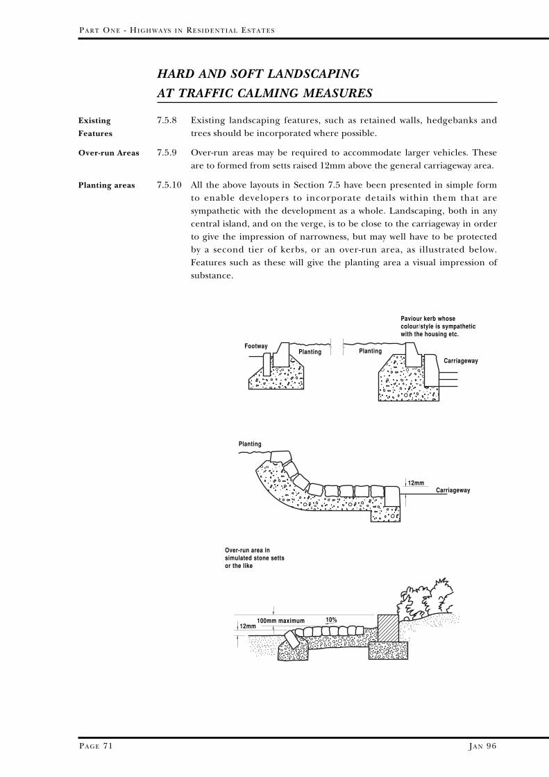
JA N 96
PA R T ON E - HI G H W A Y S I N RE S I D E N T I A L ES T A T E S
PA G E 71
HARD AND SOFT LANDSCAPING
AT TRAFFIC CALMING MEASURES
7.5.8 Existing landscaping features, such as retained walls, hedgebanks andtrees should be incorporated where possible.
7.5.9 Over-run areas may be required to accommodate larger vehicles. Theseare to formed from setts raised 12mm above the general carriageway area.
7.5.10 All the above layouts in Section 7.5 have been presented in simple formto enable developers to incorporate details within them that aresympathetic with the development as a whole. Landscaping, both in anycentral island, and on the verge, is to be close to the carriageway in orderto give the impression of narrowness, but may well have to be protectedby a second tier of kerbs, or an over-run area, as illustrated below.Features such as these will give the planting area a visual impression ofsubstance.
Existing
Features
Over-run Areas
Planting areas
PlantingPlanting
Paviour kerb whosecolour/style is sympatheticwith the housing etc.
Footway
Carriageway
Planting
Carriageway
Over-run area insimulated stone settsor the like
12mm
12mm100mm maximum 10%
JA N 96
7.5.11 In areas where the design speed of the road is 20mph or less,• no new planting likely to exceed 600mm in height should be
undertaken in visibility areas; however, trees will be accepted providedthat in combination they do not form a solid visual barrier
• no tree or shrub should be planted which would, when mature,interfere with street lighting or obscure traffic signs or signals
• certain types of trees should be avoided because of potential dangersto road users from excessive leaf fall, honey dew, falling branches,fruits and nuts etc.
7.6 CYCLEWAYS AND FOOTPATHS
7.6.1 The gradient of cycleways should not normally exceed 3%, but forlengths up to 100m it may be increased to 5%, and for up to 30m lengthsit should not exceed 7%. Steeper gradients will only be permitted forvery short lengths under difficult circumstances (see table 7.3.6).
7.6.2 Gradients are not normally to exceed 8%; however, increased gradientswill be considered provided that they are agreed with the Engineer.Special details, including surfacing, may well be required.
7.6.2 Footpaths and cycleways are to be of balanced section (or side hungwhere appropriate for drainage), but in either case the crossfalls are tobe 2.5%.
7.6.3 Edging to footpaths is to either be flush with the surface or, wheredrainage is provided for the footpath (see para 3.9.7), there is to be a12mm upstand.
7.6.4 Preformed cycle logos (rather than hand painted markings) shall beprovided so that at any point on the route at least one is visible, and alsoat points of pedestrian access. Where the cycleway is adjacent to avehicular carriageway directional arrows may need to be provided toindicate whether one or two way cycling is permitted. The relevant trafficsigns must be provided at each end of the route, and at all points where avehicular carriageway is crossed.
HI G H W A Y S I N RE S I D E N T I A L A N D CO M M E R C I A L ES T A T E S - DE S I G N GU I D E
PA G E 72
Gradients of
Cycleways
Gradient of
Footpaths
Crossfalls
Edging
Cycle Markings
and Signs
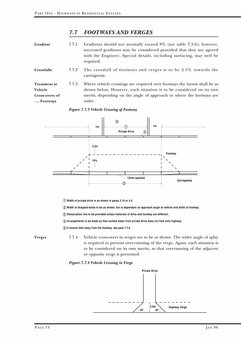
JA N 96
PA R T ON E - HI G H W A Y S I N RE S I D E N T I A L ES T A T E S
PA G E 73
7.7 FOOTWAYS AND VERGES
7.7.1 Gradients should not normally exceed 8% (see table 7.3.6); however,increased gradients may be considered provided that they are agreedwith the Engineer. Special details, including surfacing, may well berequired.
7.7.2 The crossfall of footways and verges is to be 2.5% towards thecarriageway.
7.7.3 Where vehicle crossings are required over footways the layout shall be asshown below. However, each situation is to be considered on its ownmerits, depending on the angle of approach or where the footways arewider.
Figure 7.7.3 Vehicle Crossing of Footway
Gradient
Crossfalls
Treatment at
Vehicle
Cross-overs of
.... Footways
12mm upstand
Width of private drive is as shown in paras 3.10 or 4.5.
Width of dropped kerbs to be as shown, but is dependant on approach angle of vehicle and width of footway.
Demarcation line to be provided unless materials of drive and footway are different.
Arrangements to be made so that surface water from private drive does not flow onto highway.
If access falls away from the footway, see para 7.7.6.
2.5%
10%
Private Drive
Footway
Carriageway
1m 1m1
5
2
1
2
3
3
4
5
7.7.4 Vehicle cross-overs in verges are to be as shown. The wider angle of splayis required to prevent over-running of the verge. Again, each situation isto be considered on its own merits, so that overrunning of the adjacentor opposite verge is prevented.
Figure 7.7.4 Vehicle Crossing in Verge
Verges
Private Drive
Highway Verge2.0m45°45°

7.7.5 Demarcation will be required at the highway boundary, and edgerestraint is necessary against verges.
7.7.6 In general, the levels at the back of a footway or verge should be parallelto the channel level. However, where dropped kerbs are provided foraccess to private drives etc. the cross-over will be steeper than the 2.5%specified. Therefore, where accesses and driveways fall away from theroad at a gradient steeper than 5%, it may be sensible in many instancesto lower the back edge of the footway such that an unnecessary crest incross-section is avoided, that is not only unsightly but also creates thedanger of grounding of cars entering the private drive. This cross overshould still fall toward the carriageway, but the crossfall can be reducedto 1%. Care should be taken to ensure that the longitudinal visual effectis not unpleasing.
7.7.7 To prevent surface water from flowing from the channel of thecarriageway into the private drive where the cross-over has such aminimal crossfall, thought should be given to the position of gullies inthe carriageway channel immediately upstream of the cross-over.
7.7.8 Edging to footways is to be laid with a 12mm upstand. A 150mm x 50mmedging kerb will normally suffice, but where the edge of a footway iswithin 1 metre of the top of an embankment, a full 250mm x 125mmbull-nosed kerb is to be provided with appropriate haunching andfoundations in order to provide stability to the footway.
7.7.9 Pedestrian crossing points will be required at many road junctions. Theyare to be laid out as below:
Figure 7.7.9 Pedestrian Crossing Points and Tactile Paving
HI G H W A Y S I N RE S I D E N T I A L A N D CO M M E R C I A L ES T A T E S - DE S I G N GU I D E
PA G E 74JA N 96
1
6mm upstand
1.8m
1.0m
2
Tactile paving - see paras 7.7.10 and 7.7.12
Minimum 1.8m; greater length may be requiredunder certain circumstances.
1
2
Detail of pedestrian Crossing Points
2.5%
13%
Vertical Profile
of Cross-overs
Edging to
footways
Pedestrian
Crossing Points
PA R T ON E - HI G H W A Y S I N RE S I D E N T I A L ES T A T E S
PA G E 75 JA N 96
7.7.10 Where there is no known blind or partially-sighted pedestrian activity, thepedestrian crossing places will include a single row of buff colouredtactile paving slabs, adjacent to the dropped kerbs.
7.7.11 Where significant numbers of blind or partially-sighted pedestrians areexpected, the policy contained in the Department of Transport’sDisability Unit Circular 1/91 should be followed, in consultation with theEngineer.
7.7.12 Skewed crossings are confusing, so that “straight across” crossings shouldbe used wherever possible. Although this may cause pedestrian diversion,it will minimise the crossing distance for disabled pedestrians. If skewedcrossings are unavoidable, the alignment of the tactile surface is to besuch that they “point” to the opposite dropped kerbs.
7.7.13 Highway verges shall be demarcated from non-highway land. Boundarywalls, fences and hedgebanks adequately serve this purpose, but wherethe character of the non-highway land is similar to the highway verge,markers may be provided that identify the boundary.
7.7.14 In Shared Surface Access Ways, where verges are a continuation of agarden, verge markers need be placed only at changes of direction andbetween adjacent gardens. Markers placed at these locations will besufficient when the highway boundary is defined across the drives asrequired in paragraph 7.7.5 above.
7.8 SURFACE WATER DRAINAGE
7.8.1 An adequate system of drains shall be provided for the collection anddisposal of surface water from the estate roads. The method of surfacewater disposal must be investigated at the outset with the Authorityconcerned. The developer will be required to give evidence that he has aright to discharge surface water at the proposed point of discharge, andthat he has secured satisfactory outfall arrangements. It must not beassumed that permission will automatically be given by the HighwayAuthority to make a connection to a highway drain in an adjoiningadopted County Road. Surface water from private land must beprevented from discharging on to the highway.
7.8.2 All maintainable highway drains shall be laid within the area of the estateroad and land that is to be adopted by the Highway Authority. TheHighway Authority will not adopt estate roads until the Water Authorityor its Agent has confirmed that the sewers within the estate have beenconstructed to their satisfaction and that they will be adopted by thatAuthority upon completion.
Tactile Paving
and Blind and
Partially-sighted
Pedestrians
Verge Markers
Developer’s
Obligations

7.8.3 Soakaways are not normally acceptable as a road drainage outfall;however, they will be considered in special circumstances where it can bedemonstrated to the satisfaction of the Engineer that the soakage valueof the subsoil is capable of dealing with the surface water run-off in stormconditions.
7.8.4 Details of drainage design are given below:-
HI G H W A Y S I N RE S I D E N T I A L A N D CO M M E R C I A L ES T A T E S - DE S I G N GU I D E
PA G E 76JA N 96
Design
Subsoil Drainage1 In areas of high water table a system of subsoil or French Drains
shall be provided to ensure that the water table is permanentlyreduced to 600mm below the carriageway formation level.
2) The water table level shall be determined by auguring boreholes asrequired by the Engineer.
Pipe Sizes1) The size and gradient of surface water pipelines shall be calculated
in accordance with the Lloyd-Davies method as described in RoadNote 35 (TRL), and the calculations as set out in Table 1 shall besubmitted for the approval of the Engineer together with layout anddetailed drawings.
2) The minimum diameter of a highway surface water drain shall be150mm. Where pipes are laid with less than 1.2m cover undercarriageways or 1.0m cover under footways and verges, the pipesshall have concrete protection as described in the Specification.
3) Self-cleansing gradients shall be provided to a velocity not less than0.75m/second.
4) Peak velocities above 6m/second require special attention withregard to energy dissipation and grit scour, and if the pipe leads toan open-ended discharge, velocity at outfall should not be morethan 3m/sec. unless energy dissipation is provided.
Manhole PositionsOn all surface water pipelines less than 900mm in diameter a manhole
shall be provided:-- at every change of gradient or alignment - at every change in size of pipeline - at the head of all pipelines - at every junction of pipelines (except individual gully and house
connections) - at a maximum spacing of 90m.
OutfallsOpen outfalls are to be approved by the National Rivers Authority;discharge velocity shall not be greater than 3m/sec without theprovision of energy dissipation.
PA R T ON E - HI G H W A Y S I N RE S I D E N T I A L ES T A T E S
PA G E 77 JA N 96
Gully PositionsAll gullies shall be positioned that:-
1) the area draining to each road gully shall not exceed 200 square metres,and that draining to each footpath gully shall not exceed 100 square metres
2) the spacing of gullies shall not exceed 50m in each channel on camberedroads or the lower channel on side hung roads
3) where the channel gradient is steeper than 3.3% the spacing of gullies shallnot exceed 25m to avoid excessive velocities
4) the channel gradient shall not be flatter than 1% (0.66% with precastchannels)
5) double gullies shall be provided at the low point on a concave channelprofile and at other low spots such as turning heads
6) at road junctions gullies should be sited upstream of the tangent points sothat they are not coincident with crossing points
7) where super-elevation is employed a gully should be sited just short of thepoint at which adverse camber is removed
8) the maximum length of one gully connection shall be 13m
9) gullies should be located clear of private drives and aligned to avoidcatching cyclists wheels.
Design Notes
1) The tables used for design shall be: “Tables for Hydraulic Design of Storm-Drains, Sewers and Pipelines”, Hydraulics Research Paper No.4 FourthEdition HMSO 1983.
2) The ‘K’ value used shall be in accordance with Table 9, Road Note 35Second Edition TRL.
3) Tables setting out the rainfall of any specified duration and return periodfor specified locations in Devon may be obtained from:-
The Meteorological OfficeLondon RoadBracknellBerkshire
quoting OS Grid Reference of the approximate centre of the drainage area.
4) Time of entry shall be taken as 2 minutes.
5) Unless otherwise advised the design frequency shall be 2 years.
6) Class of pipe shall be in accordance with “Simplified Tables of ExternalLoads on Buried Pipelines” (HMSO) and with “A Guide to Design Loadingsfor Buried Rigid Pipes” (HMSO 1983).

JA N 96
7.9 MAINS AND SERVICES
7.9.1 Statutory Undertakers have a right to lay their apparatus within anadoptable highway or land which is prospectively a maintainable highway.Their right to lay and maintain their apparatus is regulated by the NewRoads and Streetworks Act 1991. Within the meaning of this Act theCounty Council is the Street Authority for maintainable or prospectivelymaintainable highways.
7.9.2 As well as making provision for pedestrian and vehicular movements afunction of most residential roads and footpaths is to provide routes forstatutory and other services underground, so their efficiency and safety inuse are also matters of concern. Those who provide such services must beconsulted at an early stage of design, their requirements co-ordinated inthe design, and a balance struck between their needs and other housingobjectives, including where electricity sub-stations and gas governors aresited.
7.9.3 Consequently, developers should provide space for services either in theadopted highways (within verges or footways) or within public openspaces. The provision of mains and services is an integral part of thedesign and construction processes, and discussions must take place withthe statutory undertakers before plans are submitted for planningapproval. A co-ordinated service layout must be provided prior toentering a Section 38 Agreement.
7.9.4 All services must be located underground. However, to minimiseinstallation and repair costs and the disruption that can be caused byrepairs, services, including the main sewers, should be laid outsidecarriageways, unless no other route is available e.g. in Housing Courts orturning heads. Ducts across carriageways as required by StatutoryUndertakers or for street lighting purposes are the only cases whereservices can normally be laid in the carriageway. Developers should notethat:-(i) SEWERS must be laid in straight lines between manholes and these
should be sited in adopted areas (ii) HYDRANTS must be sited in easily accessible places after
consultation with the fire service.(iii) ELECTRICITY SUB-STATIONS, GAS GOVERNORS AND
TELEPHONE JUNCTION BOXES will require lorry access for bothinstallation and maintenance.
(iv) TELEPHONE LINES should be placed underground - distributionpoles should not be used.
7.9.5 In some locations other organisations, e.g. cable TV and other telecomscompanies, may wish to have provision made for their undergroundapparatus either when constructing the road, or at a later date.
7.9.6 Single lane carriageways and parking areas especially must be plannedwith the needs in mind of those utilities requiring jointing chambers,hydrants and link boxes, because operational vehicles need to be parkedclose to such access points whilst minimising risks of obstruction to trafficand ensuring that access to services is not obstructed.
HI G H W A Y S I N RE S I D E N T I A L A N D CO M M E R C I A L ES T A T E S - DE S I G N GU I D E
PA G E 78
Legal Position
Careful Design
Services not to
be in the
Carriageway
Parking and
Access for
Maintenance
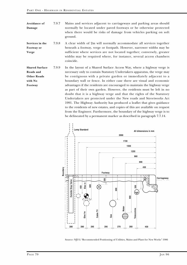
PA R T ON E - HI G H W A Y S I N RE S I D E N T I A L ES T A T E S
PA G E 79 JA N 96
7.9.7 Mains and services adjacent to carriageways and parking areas shouldnormally be located under paved footways or be otherwise protectedwhen there would be risks of damage from vehicles parking on softground.
7.9.8 A clear width of 2m will normally accommodate all services togetherbeneath a footway, verge or footpath. However, narrower widths may besufficient where services are not located together; conversely, greaterwidths may be required where, for instance, several access chamberscoincide.
7.9.9 In the layout of a Shared Surface Access Way, where a highway verge isnecessary only to contain Statutory Undertakers apparatus, the verge maybe contiguous with a private garden or immediately adjacent to aboundary wall or fence. In either case there are visual and economicadvantages if the residents are encouraged to maintain the highway vergeas part of their own garden. However, the residents must be left in nodoubt that it is a highway verge and that the rights of the StatutoryUndertakers are protected under the New roads and Streetworks Act1991. The Highway Authority has produced a leaflet that gives guidanceto the residents of new estates, and copies of this are available on requestfrom the Engineer. Furthermore, the boundary of the highway verge is tobe delineated by a permanent marker as described in paragraph 7.7.14.
Avoidance of
Damage
Services in the
Footway or
Verge
Shared Surface
Roads and
Other Roads
with No
Footway
Source: NJUG “Recommended Positioning of Utilities, Mains and Plant for New Works” 1986
2000
All dimensions in mm
Carriageway
1720
1550
1255
960
690
430
430260270295295280280
Lamp Standard
Footway
Bou
ndar
y
Out
side
Sto
p Va
lve
450 60
0
600
900
350
Tele
com
ms
250
Elec
lvEl
ec h
v
Cab
le T
V
Gas
Wat
er

7.9.10 Stopcocks or inspection pits set in the verge may need to be protected byconcrete surrounds, setts or similar solid buffer. However, this couldspoil the overall appearance of the verge or cause problems with regularmaintenance, so it is preferable that they are sited at the edge of a privatedrive.
7.9.11 Trees and shrubs in close proximity to services can cause them damage;likewise maintenance to services can cause damage to trees and shrubs.Developers should therefore consult the Engineer before any plantingscheme is approved.
7.10 STREET LIGHTING
7.10.1 Street lighting must be planned as integral part of the layout of roads andfootpaths. Adequate provision is needed to increase the sense of personalsecurity, to reduce night time accidents, to assist in the protection ofproperty, to discourage crime and vandalism, and to enhance theappearance of the scheme after dark. The Engineer will wish to designthe layout of the street lighting, but this can only be done when he isaware of what the developer is trying to achieve in terms of appearance,lamp column and lantern design etc. After the road, footway, andfootpath details have been agreed the Highway Authority will providedetails of the street lighting layout required.
7.10.2 The use of a variety of appropriate high quality lighting columns andlanterns will be encouraged wherever possible, rather than the standardcolumn seen in many existing estates. A sample of the types of columnand lantern that may be suitable is given below. The use (or reuse) of castiron columns traditional to the locality will be encouraged, as will the useof lighting mounted on wall brackets (of an appropriate design) wherebuildings are on or near the back edge of a footway, subject to approvalof equipment by the Engineer. Some locations have a style and colour oflamp columns of their own, and these are to be used as appropriate. Inenvironmentally sensitive areas, e.g. Conservation Areas, details of thetype of lighting proposed should be indicated at the time of the planningapplication.
HI G H W A Y S I N RE S I D E N T I A L A N D CO M M E R C I A L ES T A T E S - DE S I G N GU I D E
PA G E 80JA N 96
Covers and
Stopcocks in a
Verge
Planting over
Services
Overall Design
Choice of Lamp
Columns

PA R T ON E - HI G H W A Y S I N RE S I D E N T I A L ES T A T E S
PA G E 81 JA N 96
Detailed Design 7.10.3 Details of the layout and design of the street lighting scheme will formpart of the Section 38 submission, which will show the number, siting andheight of lamp columns or brackets, and lamp type and wattage. Streetlighting equipment shall be supplied and installed by the developer,unless the Highway Authority is informed in writing by the appropriateDistrict or Parish Council that a resolution has been passed objectingspecifically to the provision of street lighting and that the Parish Councilundertakes to meet the cost of lighting if this has to be installed at a laterdate. In this event, the developer shall supply and lay 100mm internaldiameter cable duct with plastic sleeve joints as and where directed by theEngineer for use in the event of the objection being reversed at a laterdate.
7.11 CUTTINGS AND EMBANKMENTS
7.11.1 The slopes of cuttings and embankments will generally be a maximum of1 in 1.5 for cuttings and 1 in 2 for embankments. However, steepercutting slopes may be acceptable if the submission is accompanied by anengineering geological assessment, and will, in any case, have to beapproved by the Engineer.
7.11.2 Other minimum dimensions and slopes are shown below:-
Figure 7.11.2 Side Slopes
600mm
1.0m to edgeof highway.
600mm
600mm
600mm
1.0m to footway or2.0m to edge of carriageway.where there is no footway
Embankment
600mm
1.0m to footway or1.5m to edge of carriageway.where there is no footway
600mm
600mm
600mm
1.0m to edge of highway.Cutting
Safe Slopes

7.12 HIGHWAY STRUCTURES
7.12.1 Where the required embankment and cutting slopes cannot be achieved,retaining walls must be provided.
7.12.2 Retaining walls and embankments that support a potential publichighway will be included in any highway adoption Agreement. Anyretaining wall that supports land above the highway will NOT be adopted.
7.12.3 Nonetheless, over and above the requirements of Section 167 of theHighways Act 1980, in developments associated with Section 38Agreements:• any retaining wall which supports land above the highway greater in
height than 1.0 metre and which is nearer than 1.5 times the height ofthe wall,
• any wall giving support to the highway that is greater in height than0.75 metre, and
• any bridge, underpass, subway or culvert which renders support to apublic highway,
shall be submitted to the Highway Authority for Technical approval. (Fordetails, see Part 3, Section 1.9). It should be noted that, where a retainingwall is adoptable, timber crib construction is not acceptable.
7.12.4 Details of any vehicle guard rails, steps and ramps and their associatedhand-rails are also to be submitted.
7.13 ACCESS FOR FIRE APPLIANCES
AND SERVICE VEHICLES
7.13.1 Access points for refuse vehicles should not normally be further than25m from dustbin collection points in houses and 9m from refuse storagechambers in flats.
7.13.2 If a fire breaks out in a building, fire appliances will need to get as closeto the building as practicable without delay. Access roads for fireappliances must therefore be included in the planning of all newbuilding developments. It is recommended that the proposals for accessfor fire appliances are verified with the Fire and Rescue Service duringthe early stages of planning the development.
HI G H W A Y S I N RE S I D E N T I A L A N D CO M M E R C I A L ES T A T E S - DE S I G N GU I D E
PA G E 82JA N 96
Retaining Walls
Adoption of
Retaining Walls
Technical
Approval of
Structures
Adjacent to the
Highway
Refuse Vehicles
General Layout
of Fire
Appliance
Access
PA R T ON E - HI G H W A Y S I N RE S I D E N T I A L ES T A T E S
PA G E 83 JA N 96
7.13.3 The following advice is based upon advice given by the Devon Fire andRescue Service which should be consulted if more details are required.a) Single or two-storey buildings with no floor higher than 6m. on any
side should have access roads that permit pumping appliances toapproach within 45m. of any point within the ground floor of thebuilding.
b) Single private dwellings (houses) may have the above requirementrelaxed so that pumping appliances should be able to approach within45m. of the front door, or to the back door where this is the nearestapproach for wheeled vehicles.
c) The minimum width of access road on the approach route to aproperty is to be 3.6m., with no gateways or other constrictionsnarrower than 3.0m.
7.13.4 Where it is proposed to construct residential buildings which exceed thesize defined above, or are in any way non-standard then the Fire andRescue Service should be consulted at the addresses shown below:-
Fire and Rescue Service, Brigade HeadquartersThe KnowleClyst St. GeorgeExeter EX3 0NW tel 01392 873711
Fire and Rescue Service, East Division HeadquartersThe KnowleClyst St. GeorgeExeter EX3 0NJ tel 01392 873711
Fire and Rescue Service, North Division HeadquartersNorth RoadPiltonBarnstaple EX31 1PA tel 01271 71515
Fire and Rescue Service, South Division HeadquartersNewton RoadTorquay TQ2 4BY tel 01803 613831
Fire and Rescue Service, West Division HeadquartersGlen RoadPlymptonPlymouth PL7 3XT tel 01752 330131
Specific
Requirements
Contact
Addresses