hilti’s team of technical support · pdf file• aci 349-01 nuclear design guide ......
TRANSCRIPT

Hilti, Inc.
7250 Dallas Parkway, Suite 1000 Plano, TX 75024
1-800-879-8000
www.hil ti.com
The following excerpt are pages from the North American Product Technical Guide, Volume 2: Anchor Fastening, Edition 16.1. Please refer to the publication in its entirety for complete details on this product including data development, product specifications, general suitability, installation, corrosion and spacing and edge distance guidelines. US: http://submittals.us.hilti.com/PTGVol2/ CA: http://submittals.us.hilti.com/PTGVol2CA/ To consult directly with a team member regarding our anchor fastening products, contact Hilti’s team of technical support specialists between the hours of 7:00am – 6:00pm CST. US: 877-749-6337 or [email protected] CA: 1-800-363-4458, ext. 6 or [email protected]

Mechanical Anchoring Systems
3.3 Mechanical Anchoring Systems
240 Hilti, Inc. (US) 1-800-879-8000 | www.us.hilti.com I en español 1-800-879-5000 I Hilti (Canada) Corp. 1-800-363-4458 I www.hilti.ca I Anchor Fastening Technical Guide 2016
HDA-P Undercut Anchor
Pre-Set Type
HDA-T Undercut Anchor Through-Set Type
3.3.1.1 Product description
3.3.1.2 Material specifications
3.3.1.3 Technical data
3.3.1.4 Installation removal instructions
3.3.1.5 Ordering information
Listings/ApprovalsICC-ES (International Code Council)ESR-1546City of Los AngelesResearch Report No. 25939European Technical ApprovalETA-99/0009ETA-99/0016Qualified under NQA-1 Nuclear Quality Program
Independent code evaluationIBC® / IRC 2015IBC® / IRC® 2012IBC® / IRC® 2009IBC® / IRC® 2006
3.3.1 HDA Undercut Anchors
3.3.1.1 Product description
The HDA undercut anchor is a heavy-duty mechanical anchor with carbide-tipped undercut segments used to perform a self-undercutting process. The HDA system includes either a HDA-P preset or HDA-T through-set style anchor, stop drill bit, setting tool, and hammer drill for M10, M12, M16 and M20 models. The HDA is available in carbon steel, stainless steel and sherardized versions. Two lengths accommodate various fixture thicknesses.
Product features
• Undercutsegmentsprovidecast-in-place like performance with limited expansion stresses
• Self-undercuttingwedgesprovidean easy, fast and reliable anchor installation
• Excellentperformanceincrackedconcrete
• Suitablefordynamicloads including seismic, fatigue and shock. See Anchor Selector Guide
• Undercutkeyingloadtransferallows for reduced edge distances and anchor spacings
• Through-setstyleprovidesincreased shear capacity
• Fullyremovable• Type316stainlesssteelfor
corrosive environments• Sherardizedzinccoatinghas
equivalent corrosion resistance to hot-dip galvanization
• ACI349-01NuclearDesignGuideis available. Call Hilti Technical Support
Guide specifications
Undercut anchors Undercut anchors shall be of an undercut style with brazed tungsten carbides on the embedded end that perform the self-undercutting process. Undercut portion of anchor shall have a minimum projected bearing area equal to or greater than 2.5 times the nominal bolt area. The bolt shall conform to ISO 898 class 8.8 strength requirements. Anchors dimensioned and supplied by Hilti.

Mechanical Anchoring Systems
HDA Undercut Anchor 3.3.1
3.3.6
3.3.6
3.3.6
3.3.6
3.3.1
3.3.2
3.3.3
3.3.6
3.3.5
3.3.6
3.3.7
3.3.8
3.3.9
3.3.6
3.3.4
Hilti, Inc. (US) 1-800-879-8000 | www.us.hilti.com I en español 1-800-879-5000 I Hilti (Canada) Corp. 1-800-363-4458 I www.hilti.ca I Anchor Fastening Technical Guide 2016 241
3.3.1.2 Material specifications
3.3.1.3 Technical data3.3.1.3.1 ACI 318-14 Chapter 17 designThe technical data contained in this section are Hilti Simplified Design Tables. The load values were developed using the Strength Design parameters and variables of ESR-1546 and the equations within ACI 318-14 Chapter 17. For a detailed explanation of the Hilti Simplified Design Tables, refer to section 3.1.8. Data tables from ESR-1546 are not contained in this section, but can be found at www.icc-es.org or at www.us.hilti.com. For technical information on the sherardized carbon steel HDA, contact Hilti Technical Support.
HDA-P and HDA-T carbon steel with electroplated zincCone bolts meet strength requirements of ISO 898, class 8.8. Minimum yield strength is 92.8 ksi (640 MPa) and minimum tensile strength is 116 ksi (800 MPa).Sleeve for the M10 and M12 has a minimum tensile strength of 123 ksi (850 MPa).Sleeve for the M16 has a minimum tensile strength of 101.5 ksi (700 MPa).Sleeve for the M20 has a minimum tensile strength of 79.8 ksi (550 MPa).The nut and washer are carbon steel.All carbon steel components have a minimum 5 µm zinc plating thickness.
HDA-PR and HDA-TR stainless steelCone bolts have a minimum yield strength is 87 ksi (600 MPa) and minimum tensile strength is 116 ksi (800 MPa).Sleeve for the M10 and M12 has a minimum tensile strength of 123 ksi (850 MPa).Sleeve for the M16 has a minimum tensile strength of 101.5 ksi (700 MPa).Nut conforms to DIN 934, grade A4-80.
HDA-PF and HDA-TF carbon steel with sherardized heavy zinc platingCone bolts meet strength requirements of ISO 898, class 8.8. Minimum yield strength is 92.8 ksi (640 MPa) and minimum tensile strength is 116 ksi (800 MPa).Sleeve for the M10 and M12 has a minimum tensile strength of 123 ksi (850 MPa).Sleeve for the M16 has a minimum tensile strength of 101.5 ksi (700 MPa).Nuts and washers are carbon steel.All carbon steel components have an average zinc plating thickness of 53 µm in accordance with ASTM A153.
Mechanical Anchoring Systems
3.3.1 HDA Undercut Anchor
242 Hilti, Inc. (US) 1-800-879-8000 | www.us.hilti.com I en español 1-800-879-5000 I Hilti (Canada) Corp. 1-800-363-4458 I www.hilti.ca I Anchor Fastening Technical Guide 2016
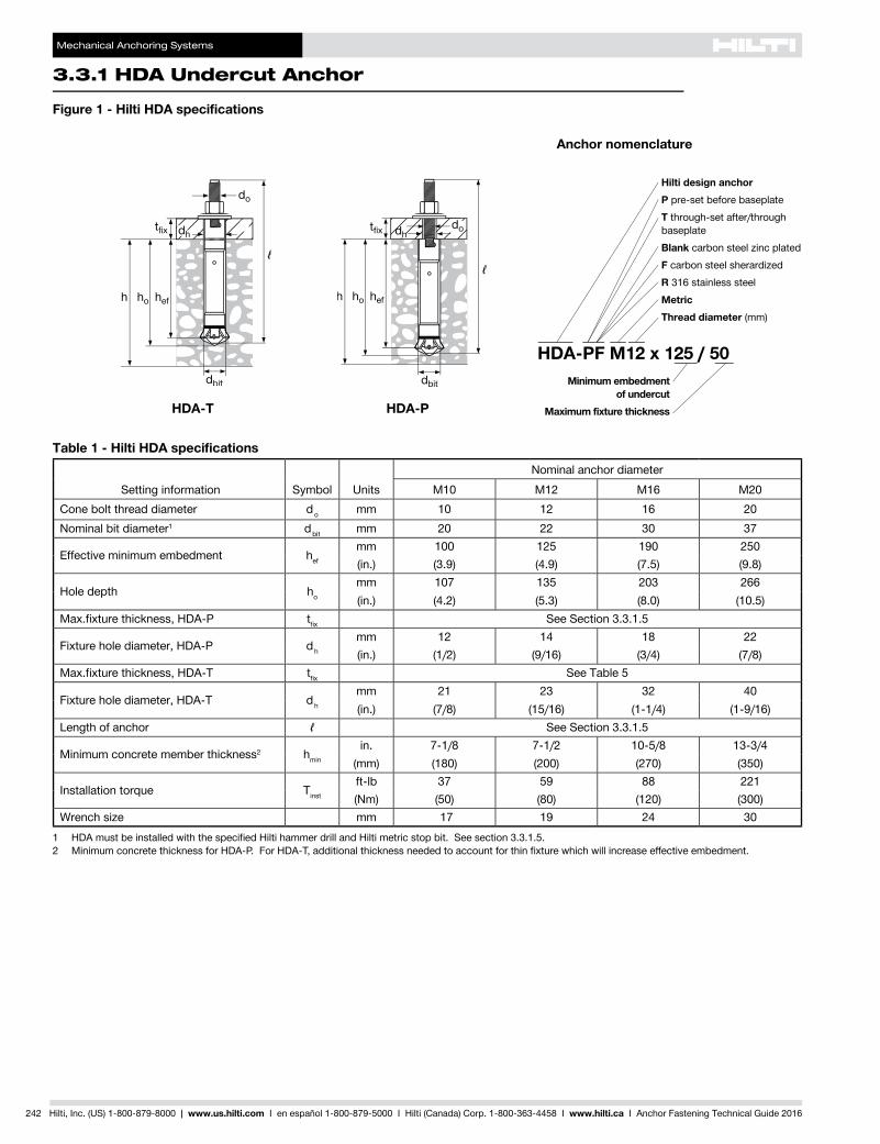
Table 1 - Hilti HDA specifications
Setting information Symbol UnitsNominal anchor diameter
M10 M12 M16 M20Cone bolt thread diameter do mm 10 12 16 20Nominal bit diameter1 dbit mm 20 22 30 37
Effective minimum embedment hef
mm 100 125 190 250(in.) (3.9) (4.9) (7.5) (9.8)
Hole depth ho
mm 107 135 203 266(in.) (4.2) (5.3) (8.0) (10.5)
Max.fixturethickness,HDA-P tfix See Section 3.3.1.5
Fixture hole diameter, HDA-P dh
mm 12 14 18 22(in.) (1/2) (9/16) (3/4) (7/8)
Max.fixturethickness,HDA-T tfix See Table 5
Fixture hole diameter, HDA-T dh
mm 21 23 32 40(in.) (7/8) (15/16) (1-1/4) (1-9/16)
Length of anchor ℓ See Section 3.3.1.5
Minimum concrete member thickness2 hmin
in. 7-1/8 7-1/2 10-5/8 13-3/4(mm) (180) (200) (270) (350)
Installation torque Tinst
ft-lb 37 59 88 221(Nm) (50) (80) (120) (300)
Wrench size mm 17 19 24 301 HDAmustbeinstalledwiththespecifiedHiltihammerdrillandHiltimetricstopbit.Seesection3.3.1.5.2 MinimumconcretethicknessforHDA-P.ForHDA-T,additionalthicknessneededtoaccountforthinfixturewhichwillincreaseeffectiveembedment.
Hilti design anchorP pre-set before baseplateT through-set after/through baseplateBlank carbon steel zinc platedF carbon steel sherardizedR 316 stainless steelMetricThread diameter (mm)
HDA-PF M12 x 125 / 50
Anchor nomenclature
Minimum embedment of undercut
Maximum fixture thickness
Figure 1 - Hilti HDA specifications
HDA-PHDA-T

Mechanical Anchoring Systems
HDA Undercut Anchor 3.3.1
3.3.6
3.3.6
3.3.6
3.3.6
3.3.1
3.3.2
3.3.3
3.3.6
3.3.5
3.3.6
3.3.7
3.3.8
3.3.9
3.3.6
3.3.4
Hilti, Inc. (US) 1-800-879-8000 | www.us.hilti.com I en español 1-800-879-5000 I Hilti (Canada) Corp. 1-800-363-4458 I www.hilti.ca I Anchor Fastening Technical Guide 2016 243
Table 2 - Hilti HDA-P and HDA-T carbon and stainless steel design strength with concrete/pullout failure in uncracked concrete1,2,3,4,5
Nominal anchor
diameter
Effective embed. mm (in.)
Tension - фNn Shear - фVn
ƒ'c = 2,500 psi lb (kN)
ƒ'c = 3,000 psi lb (kN)
ƒ'c = 4,000 psi lb (kN)"
ƒ'c = 6,000 psi lb (kN)
ƒ'c = 2,500 psi lb (kN)
ƒ'c = 3,000 psi lb (kN)
ƒ'c = 4,000 psi lb (kN)
ƒ'c = 6,000 psi lb (kN)
M10100 7,615 8,345 9,635 11,800 16,405 17,970 20,750 25,415
(3.9) (33.9) (37.1) (42.9) (52.5) (73.0) (79.9) (92.3) (113.1)
M12125 10,645 11,660 13,465 16,490 22,925 25,115 29,000 35,515
(4.9) (47.4) (51.9) (59.9) (73.4) (102.0) (111.7) (129.0) (158.0)
M16190 19,945 21,850 25,230 30,900 42,965 47,065 54,345 66,560
(7.5) (88.7) (97.2) (112.2) (137.4) (191.1) (209.4) (241.7) (296.1)
M20250 30,105 32,980 38,080 46,640 64,845 71,035 82,025 100,460
(9.8) (133.9) (146.7) (169.4) (207.5) (288.4) (316.0) (364.9) (446.9)
Table 3 - Hilti HDA-P and HDA-T carbon and stainless steel design strength with concrete/pullout failure in cracked concrete1,2,3,4,5
Nominal anchor
diameter
Effective embed. mm (in.)
Tension - фNn Shear - фVn
ƒ'c = 2,500 psi lb (kN)
ƒ'c = 3,000 psi lb (kN)
ƒ'c = 4,000 psi lb (kN)"
ƒ'c = 6,000 psi lb (kN)
ƒ'c = 2,500 psi lb (kN)
ƒ'c = 3,000 psi lb (kN)
ƒ'c = 4,000 psi lb (kN)
ƒ'c = 6,000 psi lb (kN)
M10100 5,845 6,405 7,395 9,055 13,125 14,375 16,600 20,330
(3.9) (26.0) (28.5) (32.9) (40.3) (58.4) (63.9) (73.8) (90.4)
M12125 7,305 8,005 9,240 11,320 18,340 20,090 23,200 28,415
(4.9) (32.5) (35.6) (41.1) (50.4) (81.6) (89.4) (103.2) (126.4)
M16190 14,615 16,005 18,485 22,640 34,370 37,650 43,475 53,245
(7.5) (65.0) (71.2) (82.2) (100.7) (152.9) (167.5) (193.4) (236.8)
M20250 21,920 24,010 27,725 33,955 51,875 56,830 65,620 80,365
(9.8) (97.5) (106.8) (123.3) (151.0) (230.8) (252.8) (291.9) (357.5)
1 See section 3.1.8.6 to convert design strength value to ASD value.2 Linear interpolation between embedment depths and concrete compressive strengths is not permitted.3 Apply spacing, edge distance, and concrete thickness factors in tables 6 to 9 as necessary. Compare to the steel values in tables 4 and 5.
The lesser of the values is to be used for the design.4 Tabularvaluesarefornormal-weightconcreteonly.Forsand-lightweightmultiplythedesignloadsbyλa = 0.68.5 Tabular values are for static loads only. Seismic design is not permitted for uncracked concrete. For seismic tension loads, multiply cracked
concretetabularvaluesintensiononlybyαN,seis= 0.75. No reduction needed for seismic shear. See section 3.1.8.7 for additional information on seismic applications.

Mechanical Anchoring Systems
3.3.1 HDA Undercut Anchor
244 Hilti, Inc. (US) 1-800-879-8000 | www.us.hilti.com I en español 1-800-879-5000 I Hilti (Canada) Corp. 1-800-363-4458 I www.hilti.ca I Anchor Fastening Technical Guide 2016
Table 4 - Steel strength for Hilti HDA-P carbon steel and stainless steel anchors1,2
Nominal anchor
diameter
HDA-P carbon steel anchors HDA-PR stainless steel anchors
Tensile фNsa 3
lb (kN)Shear фVsa
4 lb (kN)
Seismic shear фVsa,eq
5 lb (kN)
Tensile фNsa 3
lb (kN)Shear фVsa
4 lb (kN)
Seismic shear фVsa,eq
5 lb (kN)
M107,830 3,260 2,920 7,830 3,945 3,655
(34.8) (14.5) (13.0) (34.8) (17.5) (16.3)
M1211,395 4,735 4,235 11,395 5,845 5,260
(50.7) (21.1) (18.8) (50.7) (26.0) (23.4)
M1621,140 8,810 7,890 21,140 10,960 9,790
(94.0) (39.2) (35.1) (94.0) (48.8) (43.5)
M2033,060 13,500 12,130
n/a n/a n/a(147.1) (60.1) (54.0)
1 See section 3.1.8.6 to convert design strength value to ASD value.2 Hilti HDA-P Carbon and Stainless steel anchors are to be considered ductile steel elements.3 Tensile=фAse,N futa as noted in ACI 318-14 Chapter 17.4 ShearvaluesdeterminedbystaticsheartestswithфVsa≤ф0.60Ase,V futa as noted in ACI 318-14 Chapter 17.5 SeismicshearvaluesdeterminedbyseismicsheartestswithфVsa,eq≤ф0.60Ase,V futa as noted in ACI 318-14 Chapter 17.
See section 3.1.8.7 for additional information on seismic applications.
Table 5 - Steel strength for Hilti HDA-T carbon steel and stainless steel anchors1,2
Nominal anchor
diameter
Thickness of fastened parts tfix
in. (mm)
HDA-T carbon steel anchors HDA-TR stainless steel anchors
Tensile фNsa 3
lb (kN)Shear фVsa
4 lb (kN)
Seismic shear фVsa,eq
5 lb (kN)
Tensile фNsa 3
lb (kN)Shear фVsa
4 lb (kN)
Seismic shear фVsa,eq
5 lb (kN)
M105/8≤tfix < 13/16 7,830 9,060 8,185 7,830 10,080 9,060
(15≤tfix < 20) (34.8) (40.3) (36.4) (34.8) (44.8) (40.3)
M12
5/8≤tfix < 13/16
11,395 (50.7)
10,815 9,790
11,395 (50.7)
13,155 11,690
(15≤tfix < 20) (48.1) (43.5) (58.5) (52.0)
13/16≤tfix < 2 12,130 10,815 14,465 13,005
(20≤tfix < 50) (54.0) (48.1) (64.3) (57.8)
M16
13/16≤tfix < 1
21,140 (94.0)
19,875 17,825
21,140 (94.0)
23,235 20,900
(20≤tfix < 25) (88.4) (79.3) (103.4) (93.0)
1≤tfix < 1-3/16 22,505 20,315 24,550 22,065
(25≤tfix < 30) (100.1) (90.4) (109.2) (98.1)
1-3/16≤tfix < 1-3/8 24,845 22,355 25,715 23,090
(30≤tfix < 35) (110.5) (99.4) (114.4) (102.7)
1-3/8≤tfix < 2-3/8 26,885 24,110 26,595 23,965
(35≤tfix < 60) (119.6) (107.2) (118.3) (106.6)
M20
1≤tfix < 1-9/16
33,060 (147.1)
29,370 26,450
n/a n/a n/a
(25≤tfix < 40) (130.6) (117.7)
1-9/16≤tfix < 2-1/8 33,025 29,665
(40≤tfix < 55) (146.9) (132.0)
2-1/8≤tfix < 4 35,510 32,005
(55≤tfix < 100) (158.0) (142.4)
1 See section 3.1.8.6 to convert design strength value to ASD value.2 Hilti HDA-T Carbon and Stainless steel anchors are to be considered ductile steel elements.3 Tensile=фAse,N futa as noted in ACI 318-14 Chapter 174 ShearvaluesdeterminedbystaticsheartestswithфVsa≤ф0.60Ase,V futa as noted in ACI 318-14 Chapter 175 SeismicshearvaluesdeterminedbyseismicsheartestswithфVsa,eq≤ф0.60Ase,V futa as noted in ACI 318-14 Chapter 17
See section 3.1.8.7 for additional information on seismic applications.

Mechanical Anchoring Systems
HDA Undercut Anchor 3.3.1
3.3.6
3.3.6
3.3.6
3.3.6
3.3.1
3.3.2
3.3.3
3.3.6
3.3.5
3.3.6
3.3.7
3.3.8
3.3.9
3.3.6
3.3.4
Hilti, Inc. (US) 1-800-879-8000 | www.us.hilti.com I en español 1-800-879-5000 I Hilti (Canada) Corp. 1-800-363-4458 I www.hilti.ca I Anchor Fastening Technical Guide 2016 245
Table 6 - Load adjustment factors for M10 and M12 Hilti HDA-P and HDA-T carbon and stainless steel anchors in uncracked concrete1,2
M10 and M12HDA-P and HDA-Tuncracked concrete
Spacing factor in tension
ƒAN
Edge distance factor in tension
ƒRN
Spacing factor in shear 3
ƒAV
Edge distance in shearConc. thickness factor in shear 4
ƒHV
⊥toward edgeƒRV
II to and away from edge
ƒRV
Nominal diameter M10 M12 M10 M12 M10 M12 M10 M12 M10 M12 M10 M12Effective
embedment hef
mm 100 125 100 125 100 125 100 125 100 125 100 125(in.) (3.94) (4.92) (3.94) (4.92) (3.94) (4.92) (3.94) (4.92) (3.94) (4.92) (3.94) (4.92)
Spac
ing
(s) /
edg
e di
stan
ce (c
a ) /
con
cret
eth
ickn
ess
(h) -
in. (
mm
)
3-1/8 (79) n/a n/a 0.66 n/a n/a n/a 0.14 n/a 0.28 n/a n/a n/a3-1/2 (89) n/a n/a 0.70 n/a n/a n/a 0.17 n/a 0.33 n/a n/a n/a
4 (102) 0.67 n/a 0.76 0.66 0.56 n/a 0.20 0.15 0.40 0.31 n/a n/a4-1/2 (114) 0.69 n/a 0.82 0.71 0.56 n/a 0.24 0.18 0.48 0.37 n/a n/a
5 (127) 0.71 0.67 0.88 0.76 0.57 0.56 0.28 0.22 0.56 0.43 n/a n/a6 (152) 0.75 0.70 1.00 0.86 0.59 0.57 0.37 0.28 0.74 0.57 n/a n/a7 (178) 0.80 0.74 0.96 0.60 0.58 0.47 0.36 0.93 0.71 n/a n/a
7-1/8 (181) 0.80 0.74 0.97 0.60 0.59 0.48 0.37 0.96 0.73 0.64 n/a7-1/2 (191) 0.82 0.75 1.00 0.61 0.59 0.52 0.40 1.00 0.79 0.66 n/a
8 (203) 0.84 0.77 0.61 0.60 0.57 0.44 0.87 0.68 0.629 (229) 0.88 0.80 0.63 0.61 0.68 0.52 1.00 0.72 0.66
10 (254) 0.92 0.84 0.64 0.62 0.80 0.61 0.76 0.6911 (279) 0.97 0.87 0.66 0.63 0.92 0.70 0.79 0.7312 (305) 1.00 0.91 0.67 0.64 1.00 0.80 0.83 0.7614 (356) 0.97 0.70 0.67 1.00 0.90 0.8216 (406) 1.00 0.73 0.69 0.96 0.8818 (457) 0.76 0.72 1.00 0.9320 (508) 0.79 0.74 0.9824 (610) 0.84 0.79 1.0030 (762) 0.93 0.8636 (914) 1.00 0.9342 (1067) 1.00
Table 7 - Load adjustment factors for M10 and M12 Hilti HDA-P and HDA-T carbon and stainless steel anchors in cracked concrete1,2
M10 and M12HDA-P and HDA-Tcracked concrete
Spacing factor in tension
ƒAN
Edge distance factor in tension
ƒRN
Spacing factor in shear 3
ƒAV
Edge distance in shearConc. thickness factor in shear 4
ƒHV
⊥toward edgeƒRV
II to and away from edge
ƒRV
Nominal diameter M10 M12 M10 M12 M10 M12 M10 M12 M10 M12 M10 M12Effective
embedment hef
mm 100 125 100 125 100 125 100 125 100 125 100 125(in.) (3.94) (4.92) (3.94) (4.92) (3.94) (4.92) (3.94) (4.92) (3.94) (4.92) (3.94) (4.92)
Spac
ing
(s) /
edg
e di
stan
ce (c
a ) /
con
cret
eth
ickn
ess
(h) -
in. (
mm
)
3-1/8 (79) n/a n/a 0.66 n/a n/a n/a 0.12 n/a 0.25 n/a n/a n/a3-1/2 (89) n/a n/a 0.70 n/a n/a n/a 0.15 n/a 0.29 n/a n/a n/a
4 (102) 0.67 n/a 0.76 0.66 0.55 n/a 0.18 0.14 0.36 0.27 n/a n/a4-1/2 (114) 0.69 n/a 0.82 0.71 0.56 n/a 0.21 0.16 0.43 0.33 n/a n/a
5 (127) 0.71 0.67 0.88 0.76 0.57 0.56 0.25 0.19 0.50 0.38 n/a n/a6 (152) 0.75 0.70 1.00 0.86 0.58 0.57 0.33 0.25 0.66 0.50 n/a n/a7 (178) 0.80 0.74 0.96 0.59 0.58 0.42 0.32 0.83 0.64 n/a n/a
7-1/8 (181) 0.80 0.74 0.97 0.59 0.58 0.43 0.33 0.86 0.65 0.62 n/a7-1/2 (191) 0.82 0.75 1.00 0.60 0.58 0.46 0.35 0.92 0.71 0.63 n/a
8 (203) 0.84 0.77 0.61 0.59 0.51 0.39 1.00 0.78 0.65 0.609 (229) 0.88 0.80 0.62 0.60 0.61 0.46 0.93 0.69 0.63
10 (254) 0.92 0.84 0.63 0.61 0.71 0.54 1.00 0.73 0.6711 (279) 0.97 0.87 0.65 0.62 0.82 0.63 0.76 0.7012 (305) 1.00 0.91 0.66 0.63 0.94 0.71 0.80 0.7314 (356) 0.97 0.69 0.66 1.00 0.90 0.86 0.7916 (406) 1.00 0.71 0.68 1.00 0.92 0.8418 (457) 0.74 0.70 0.98 0.8920 (508) 0.77 0.72 1.00 0.9424 (610) 0.82 0.77 1.0030 (762) 0.90 0.8336 (914) 0.98 0.9042 (1067) 1.00 0.97
> 48 (1219) 1.001 Linear interpolation not permitted.2 When combining multiple load adjustment factors (e.g. for a 4 anchor pattern in a corner with thin concrete member) the design can become very conservative.
To optimize the design, use Hilti PROFIS Anchor Design software or perform anchor calculation using design equations from ACI 318-14 Chapter 17.3 Spacing factor reduction in shear, ƒAV,assumesaninfluenceofanearbyedge.Ifnoedgeexists,thenƒAV = ƒAN.4 Concrete thickness reduction ƒactor in shear, ƒHV,assumesaninfluenceofanearbyedge.Ifnoedgeexists,thenƒHV = 1.0.

Mechanical Anchoring Systems
3.3.1 HDA Undercut Anchor
246 Hilti, Inc. (US) 1-800-879-8000 | www.us.hilti.com I en español 1-800-879-5000 I Hilti (Canada) Corp. 1-800-363-4458 I www.hilti.ca I Anchor Fastening Technical Guide 2016
Table 8 - Load adjustment factors for M16 and M20 Hilti HDA-P and HDA-T carbon and stainless steel anchors in uncracked concrete1,2
M16 and M20HDA-P and HDA-Tuncracked concrete
Spacing factor in tension
ƒAN
Edge distance factor in tension
ƒRN
Spacing factor in shear 3
ƒAV
Edge distance in shearConc. thickness factor in shear 4
ƒHV
⊥toward edgeƒRV
II to and away from edge
ƒRV
Nominal diameter M16 M20 M16 M20 M16 M20 M16 M20 M16 M20 M16 M20Effective
embedment hef
mm 190 250 190 250 190 250 190 250 190 250 190 250(in.) (7.48) (9.84) (7.48) (9.84) (7.48) (9.84) (7.48) (9.84) (7.48) (9.84) (7.48) (9.84)
Spac
ing
(s) /
edg
e di
stan
ce (c
a ) /
con
cret
eth
ickn
ess
(h) -
in. (
mm
)
6 (152) n/a n/a 0.66 n/a n/a n/a 0.15 n/a 0.30 n/a n/a n/a7 (178) n/a n/a 0.72 n/a n/a n/a 0.19 n/a 0.38 n/a n/a n/a
7-1/8 (181) n/a n/a 0.73 n/a n/a n/a 0.20 n/a 0.39 n/a n/a n/a7-1/2 (191) 0.67 n/a 0.75 n/a 0.56 n/a 0.21 n/a 0.42 n/a n/a n/a
8 (203) 0.68 n/a 0.78 0.66 0.56 n/a 0.23 0.15 0.46 0.31 n/a n/a9 (229) 0.70 n/a 0.85 0.71 0.57 n/a 0.28 0.18 0.55 0.37 n/a n/a
10 (254) 0.72 0.67 0.91 0.76 0.58 0.56 0.32 0.22 0.65 0.43 n/a n/a11 (279) 0.75 0.69 0.98 0.81 0.59 0.57 0.37 0.25 0.75 0.50 0.59 n/a12 (305) 0.77 0.70 1.00 0.86 0.59 0.57 0.43 0.28 0.85 0.57 0.61 n/a14 (356) 0.81 0.74 0.96 0.61 0.58 0.54 0.36 1.00 0.71 0.66 0.5816 (406) 0.86 0.77 1.00 0.63 0.60 0.66 0.44 0.87 0.71 0.6218 (457) 0.90 0.80 0.64 0.61 0.78 0.52 1.00 0.75 0.6620 (508) 0.95 0.84 0.66 0.62 0.92 0.61 0.79 0.6924 (610) 1.00 0.91 0.69 0.64 1.00 0.80 0.87 0.7630 (762) 1.00 0.74 0.68 1.00 0.97 0.8536 (914) 0.78 0.72 1.00 0.9342 (1067) 0.83 0.75 1.00
> 48 (1219) 0.88 0.79
Table 9 - Load adjustment factors for M16 and M20 Hilti HDA-P and HDA-T carbon and stainless steel anchors in cracked concrete1,2
M16 and M20HDA-P and HDA-Tcracked concrete
Spacing factor in tension
ƒAN
Edge distance factor in tension
ƒRN
Spacing factor in shear 3
ƒAV
Edge distance in shearConc. thickness factor in shear 4
ƒHV
⊥toward edgeƒRV
II to and away from edge
ƒRV
Nominal diameter M16 M20 M16 M20 M16 M20 M16 M20 M16 M20 M16 M20Effective
embedment hef
mm 190 250 190 250 190 250 190 250 190 250 190 250(in.) (7.48) (9.84) (7.48) (9.84) (7.48) (9.84) (7.48) (9.84) (7.48) (9.84) (7.48) (9.84)
Spac
ing
(s) /
edg
e di
stan
ce (c
a ) /
con
cret
eth
ickn
ess
(h) -
in. (
mm
)
6 (152) n/a n/a 0.66 n/a n/a n/a 0.13 n/a 0.27 n/a n/a n/a7 (178) n/a n/a 0.72 n/a n/a n/a 0.17 n/a 0.34 n/a n/a n/a
7-1/8 (181) n/a n/a 0.73 n/a n/a n/a 0.17 n/a 0.35 n/a n/a n/a7-1/2 (191) 0.67 n/a 0.75 n/a 0.55 n/a 0.19 n/a 0.38 n/a n/a n/a
8 (203) 0.68 n/a 0.78 0.66 0.56 n/a 0.21 0.14 0.41 0.27 n/a n/a9 (229) 0.70 n/a 0.85 0.71 0.57 n/a 0.25 0.16 0.49 0.33 n/a n/a
10 (254) 0.72 0.67 0.91 0.76 0.57 0.56 0.29 0.19 0.58 0.38 n/a n/a11 (279) 0.75 0.69 0.98 0.81 0.58 0.56 0.33 0.22 0.67 0.44 0.57 n/a12 (305) 0.77 0.70 1.00 0.86 0.59 0.57 0.38 0.25 0.76 0.50 0.59 n/a14 (356) 0.81 0.74 0.96 0.60 0.58 0.48 0.32 0.96 0.64 0.64 0.5616 (406) 0.86 0.77 1.00 0.62 0.59 0.59 0.39 1.00 0.78 0.68 0.6018 (457) 0.90 0.80 0.63 0.60 0.70 0.46 0.93 0.72 0.6320 (508) 0.95 0.84 0.65 0.61 0.82 0.54 1.00 0.76 0.6724 (610) 1.00 0.91 0.68 0.63 1.00 0.71 0.84 0.7330 (762) 1.00 0.72 0.67 1.00 0.94 0.8236 (914) 0.76 0.70 1.00 0.8942 (1067) 0.81 0.73 0.97
> 48 (1219) 0.85 0.77 1.001 Linear interpolation not permitted.2 When combining multiple load adjustment factors (e.g. for a 4 anchor pattern in a corner with thin concrete member) the design can become very conservative.
To optimize the design, use Hilti PROFIS Anchor Design software or perform anchor calculation using design equations from ACI 318-14 Chapter 17.3 Spacing factor reduction in shear, ƒAV,assumesaninfluenceofanearbyedge.Ifnoedgeexists,thenƒAV = ƒAN.4 Concrete thickness reduction factor in shear, ƒHV,assumesaninfluenceofanearbyedge.Ifnoedgeexists,thenƒHV = 1.0.
Mechanical Anchoring Systems
HDA Undercut Anchor 3.3.1
3.3.6
3.3.6
3.3.6
3.3.6
3.3.2
3.3.3
3.3.6
3.3.5
3.3.6
3.3.7
3.3.8
3.3.9
3.3.6
3.3.4
3.3.1c
Hilti, Inc. (US) 1-800-879-8000 | www.us.hilti.com I en español 1-800-879-5000 I Hilti (Canada) Corp. 1-800-363-4458 I www.hilti.ca I Anchor Fastening Technical Guide 2016 247
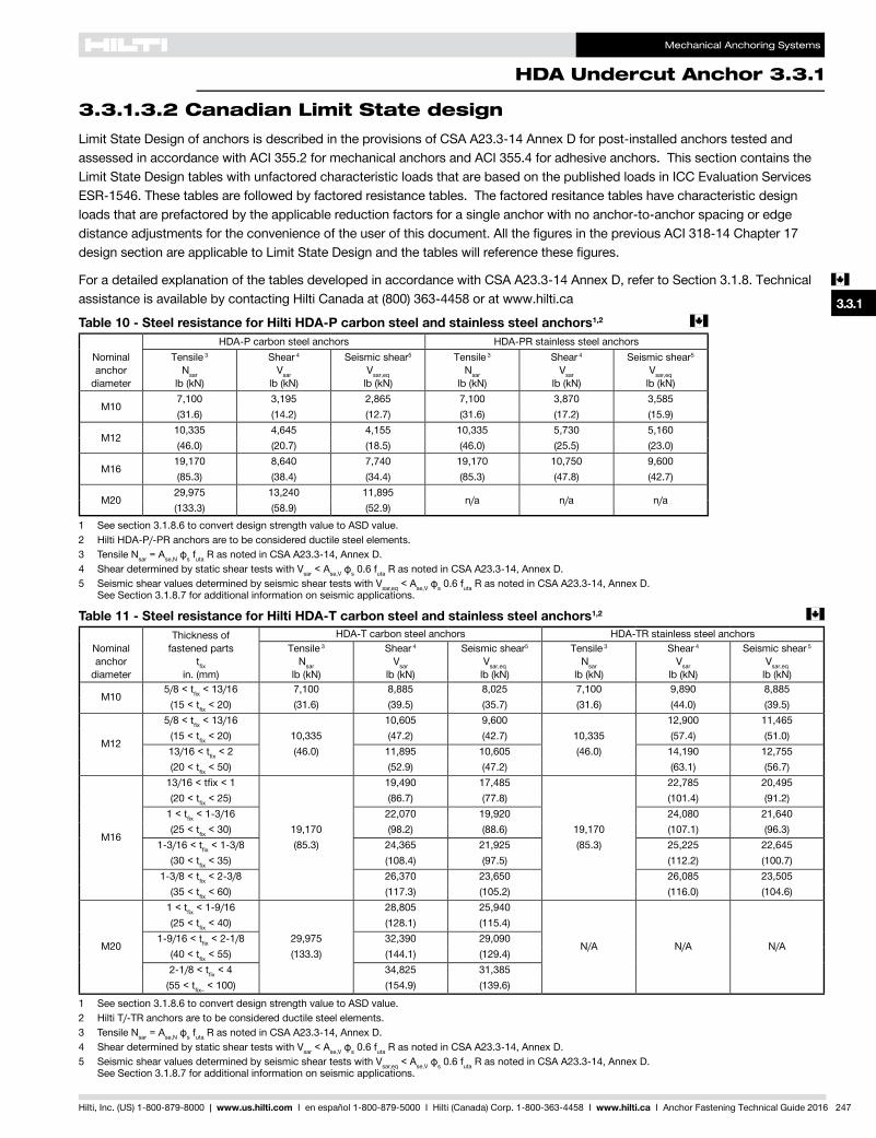
3.3.1.3.2 Canadian Limit State designLimit State Design of anchors is described in the provisions of CSA A23.3-14 Annex D for post-installed anchors tested and assessed in accordance with ACI 355.2 for mechanical anchors and ACI 355.4 for adhesive anchors. This section contains the Limit State Design tables with unfactored characteristic loads that are based on the published loads in ICC Evaluation Services ESR-1546. These tables are followed by factored resistance tables. The factored resitance tables have characteristic design loads that are prefactored by the applicable reduction factors for a single anchor with no anchor-to-anchor spacing or edge distance adjustments for the convenience of the user of this document. All the figures in the previous ACI 318-14 Chapter 17 design section are applicable to Limit State Design and the tables will reference these figures.
For a detailed explanation of the tables developed in accordance with CSA A23.3-14 Annex D, refer to Section 3.1.8. Technical assistance is available by contacting Hilti Canada at (800) 363-4458 or at www.hilti.ca
Table 11 - Steel resistance for Hilti HDA-T carbon steel and stainless steel anchors1,2 c
Nominal anchor
diameter
Thickness of fastened parts
tfix in. (mm)
HDA-T carbon steel anchors HDA-TR stainless steel anchorsTensile 3
Nsar lb (kN)
Shear 4 Vsar
lb (kN)
Seismic shear5 Vsar,eq
lb (kN)
Tensile 3 Nsar
lb (kN)
Shear 4 Vsar
lb (kN)
Seismic shear 5 Vsar,eq
lb (kN)
M105/8 < tfix < 13/16 7,100 8,885 8,025 7,100 9,890 8,885
(15 < tfix < 20) (31.6) (39.5) (35.7) (31.6) (44.0) (39.5)
M12
5/8 < tfix < 13/16 10,605 9,600 12,900 11,465(15 < tfix < 20) 10,335 (47.2) (42.7) 10,335 (57.4) (51.0)13/16 < tfix < 2 (46.0) 11,895 10,605 (46.0) 14,190 12,755(20 < tfix < 50) (52.9) (47.2) (63.1) (56.7)
M16
13/16 < tfix < 1 19,490 17,485 22,785 20,495(20 < tfix < 25) (86.7) (77.8) (101.4) (91.2)
1 < tfix < 1-3/16 22,070 19,920 24,080 21,640(25 < tfix < 30) 19,170 (98.2) (88.6) 19,170 (107.1) (96.3)
1-3/16 < tfix < 1-3/8 (85.3) 24,365 21,925 (85.3) 25,225 22,645(30 < tfix < 35) (108.4) (97.5) (112.2) (100.7)
1-3/8 < tfix < 2-3/8 26,370 23,650 26,085 23,505(35 < tfix < 60) (117.3) (105.2) (116.0) (104.6)
M20
1 < tfix < 1-9/16 28,805 25,940
N/A N/A N/A
(25 < tfix < 40) (128.1) (115.4)1-9/16 < tfix < 2-1/8 29,975 32,390 29,090
(40 < tfix < 55) (133.3) (144.1) (129.4)2-1/8 < tfix < 4 34,825 31,385
(55 < tfix– < 100) (154.9) (139.6)
1 See section 3.1.8.6 to convert design strength value to ASD value.2 Hilti T/-TR anchors are to be considered ductile steel elements.3 Tensile Nsar = Ase,Nфs futa R as noted in CSA A23.3-14, Annex D.4 Shear determined by static shear tests with Vsar < Ase,Vфs 0.6 futa R as noted in CSA A23.3-14, Annex D.5 Seismic shear values determined by seismic shear tests with Vsar,eq < Ase,Vфs 0.6 futa R as noted in CSA A23.3-14, Annex D.
See Section 3.1.8.7 for additional information on seismic applications.
Table 10 - Steel resistance for Hilti HDA-P carbon steel and stainless steel anchors1,2 c
Nominal anchor
diameter
HDA-P carbon steel anchors HDA-PR stainless steel anchorsTensile 3
Nsar lb (kN)
Shear 4 Vsar
lb (kN)
Seismic shear5 Vsar,eq
lb (kN)
Tensile 3 Nsar
lb (kN)
Shear 4 Vsar
lb (kN)
Seismic shear5 Vsar,eq
lb (kN)
M107,100 3,195 2,865 7,100 3,870 3,585(31.6) (14.2) (12.7) (31.6) (17.2) (15.9)
M1210,335 4,645 4,155 10,335 5,730 5,160(46.0) (20.7) (18.5) (46.0) (25.5) (23.0)
M1619,170 8,640 7,740 19,170 10,750 9,600(85.3) (38.4) (34.4) (85.3) (47.8) (42.7)
M2029,975 13,240 11,895
n/a n/a n/a(133.3) (58.9) (52.9)
1 See section 3.1.8.6 to convert design strength value to ASD value.2 Hilti HDA-P/-PR anchors are to be considered ductile steel elements.3 Tensile Nsar = Ase,Nфs futa R as noted in CSA A23.3-14, Annex D.4 Shear determined by static shear tests with Vsar < Ase,Vфs 0.6 futa R as noted in CSA A23.3-14, Annex D.5 Seismic shear values determined by seismic shear tests with Vsar,eq < Ase,Vфs 0.6 futa R as noted in CSA A23.3-14, Annex D.
See Section 3.1.8.7 for additional information on seismic applications.

Mechanical Anchoring Systems
3.3.1 HDA Undercut Anchor
248 Hilti, Inc. (US) 1-800-879-8000 | www.us.hilti.com I en español 1-800-879-5000 I Hilti (Canada) Corp. 1-800-363-4458 I www.hilti.ca I Anchor Fastening Technical Guide 2016
Table 12 - Hilti HDA carbon and stainless steel design information in accordance with CSA A23.3-141 c
Design parameter Symbol UnitsNominal anchor diameter
RefA23.3-14M10 M12 M16 M20
HDA HDA-R HDA HDA-R HDA HDA-R HDA
Anchor O.D. da
in. 19 21 29 35(mm) (0.75) (0.83) (1.14) (1.38)
Effective minimum embedment2 hef
in. 100 125 190 250(mm) (3.94) (4.92) (7.48) (9.84)
Min. concrete thickness hmin - See tables 1 of this section, or 3A and 3B of ESR-1546Critical edge distance cac - 1.5 x hef : See section 4.1.11 of ESR-1546
Min. edge distance cmin
in. 80 100 150 200(mm) (3.15) (3.94) (5.91) (7.87)
Min. anchor spacing smin
in. 100 125 190 250(mm) (3.94) (4.92) (7.48) (9.84)
Min.specifiedyieldstrength fya
psi 92,800(N/mm2) (640)
Min.specifiedult.strength futa
psi 116,000(N/mm2) (800)
Effective tensile stress area Ase,N
in2 0.090 0.131 0.243 0.380(mm2) (58.1) (84.5) (156.8) (245.2)
Steel embed. material resistance factor for reinforcement фs - 0.85 8.4.3
Resistancemodificationfactorfortension,steelfailure modes3 R - 0.80 D.5.3
Resistancemodificationfactorforshear,steelfailure modes3 R - 0.75 D.5.3
Factored steel resistance in tension Nsar - See tables 10 and 11 of this section D.6.1.2Factored steel resistance in shear Vsar - See tables 10 and 11 of this section D.7.1.2Factored steel resistance in shear, seismic Vsar,eq - See tables 10 and 11 of this sectionCoeff. for factored concrete breakout resistance, uncracked concrete kc,uncr - 12.5 D.6.2.2
Coeff. for factored concrete breakout resistance, cracked concrete kc,cr - 10 D.6.2.2
Modification factor for anchor resistance, tension, uncracked concrete4 ψc,N - 1.0 D.6.2.6
Anchor category - - 1 D.5.3 (c )Concrete material resistance factor фc - 0.65 8.4.2Resistancemodificationfactorfortensionandshear, concrete failure modes, Condition B5 R - 1.00 D.5.3 (c )
Factored pullout resistance in 20 MPa uncracked concrete6 Npr,uncr
lbN/A D.6.3.2
(kN)
Factored pullout resistance in 20 MPa cracked concrete6 Npr,cr
lb 6,295 7,870 15,745 23,615D.6.3.2
(kN) (28.0) (35.0) (70.0) (105.0)
1 Design information in this table is taken from ICC-ES ESR-1546, dated March 2016, and converted for use with CSA A23.3-14 Annex D.2 Seefigure1ofthissection.3 TheHDAisconsideredaductilesteelelementasdefinedbyCSAA23.3-14AnnexDsectionD.2.4 Foralldesigncases,ψc,N=1.0.Theappropriatecoefficientforbreakoutresistanceforcrackedconcrete(kc,cr) or uncracked concrete (kc,uncr) must be used.5 For use with the load combinations of CSA A23.3-14 chapter 8. Condition B applies where supplementary reinforcement in conformance with CSA A23.3-14
sectionD.5.3isnotprovided,orwherepulloutorpryoutstrengthgoverns.Forcaseswherethepresenceofsupplementaryreinforcementcanbeverified, theresistancemodificationfactorsassociatedwithConditionAmaybeused.
6 Foralldesigncases,ψc,P = 1.0. NA (not applicable) denotes that this value does not control for design. See section 4.1.4 of ESR-1546 for additional information.

Mechanical Anchoring Systems
HDA Undercut Anchor 3.3.1
3.3.6
3.3.6
3.3.6
3.3.6
3.3.2
3.3.3
3.3.6
3.3.5
3.3.6
3.3.7
3.3.8
3.3.9
3.3.6
3.3.4
3.3.1c
Hilti, Inc. (US) 1-800-879-8000 | www.us.hilti.com I en español 1-800-879-5000 I Hilti (Canada) Corp. 1-800-363-4458 I www.hilti.ca I Anchor Fastening Technical Guide 2016 249
Table 13 - Hilti HDA-P and HDA-T carbon and stainless steel factored resistance with concrete/pullout failure c
in uncracked concrete1,2,3,4,5
Nominal anchor
diameter
Effective embed. mm (in.)
Tension - Nr Shear - Vr
ƒ'c = 20 MPa (2,900 psi)
lb (kN)
ƒ'c = 25 MPa (3,625 psi)
lb (kN)
ƒ'c = 30 MPa (4,350 psi)
lb (kN)
ƒ'c = 40 MPa (5,800 psi)
lb (kN)
ƒ'c = 20 MPa (2,900 psi)
lb (kN)
ƒ'c = 25 MPa (3,625 psi)
lb (kN)
ƒ'c = 30 MPa (4,350 psi)
lb (kN)
ƒ'c = 40 MPa (5,800 psi)
lb (kN)
M10100 8,170 9,135 10,005 11,550 16,335 18,265 20,010 23,105
(3.94) (36.3) (40.6) (44.5) (51.4) (72.7) (81.3) (89.0) (102.8)
M12125 11,415 12,765 13,980 16,145 22,830 25,525 27,965 32,290
(4.92) (50.8) (56.8) (62.2) (71.8) (101.6) (113.6) (124.4) (143.6)
M16190 21,395 23,920 26,200 30,255 42,785 47,840 52,405 60,510
(7.48) (95.2) (106.4) (116.6) (134.6) (190.3) (212.8) (233.1) (269.2)
M20250 32,290 36,100 39,545 45,665 64,580 72,200 79,095 91,330
(9.84) (143.6) (160.6) (175.9) (203.1) (287.3) (321.2) (351.8) (406.3)
Table 14 - Hilti HDA-P and HDA-T carbon and stainless steel factored resistance with concrete/pullout failure c in cracked concrete1,2,3,4,5
Nominal anchor
diameter
Effective embed. mm (in.)
Tension - Nr Shear - Vr
ƒ'c = 20 MPa (2,900 psi)
lb (kN)
ƒ'c = 25 MPa (3,625 psi)
lb (kN)
ƒ'c = 30 MPa (4,350 psi)
lb (kN)
ƒ'c = 40 MPa (5,800 psi)
lb (kN)
ƒ'c = 20 MPa (2,900 psi)
lb (kN)
ƒ'c = 25 MPa (3,625 psi)
lb (kN)
ƒ'c = 30 MPa (4,350 psi)
lb (kN)
ƒ'c = 40 MPa (5,800 psi)
lb (kN)
M10100 6,295 7,040 7,710 8,905 13,070 14,615 16,005 18,485
(3.94) (28.0) (31.3) (34.3) (39.6) (58.1) (65.0) (71.2) (82.2)
M12125 7,870 8,800 9,640 11,130 18,265 20,420 22,370 25,830
(4.92) (35.0) (39.1) (42.9) (49.5) (81.3) (90.8) (99.5) (114.9)
M16190 15,745 17,600 19,280 22,265 34,230 38,270 41,925 48,410
(7.48) (70.0) (78.3) (85.8) (99.0) (152.3) (170.2) (186.5) (215.3)
M20250 23,615 26,400 28,920 33,395 51,665 57,760 63,275 73,065
(9.84) (105.0) (117.4) (128.6) (148.5) (229.8) (256.9) (281.5) (325.0)
1 See section 3.1.8.6 to convert design strength value to ASD value.2 Linear interpolation between embedment depths and concrete compressive strengths is not permitted.3 Apply spacing, edge distance, and concrete thickness factors in tables 6 to 9 as necessary. Compare to the steel values in tables 10 and 11.
The lesser of the values is to be used for the design.4 Tabularvaluesarefornormal-weightconcreteonly.Forlightweightconcretemultiplydesignstrengthbyλa as follows:
forsand-lightweight,λa=0.68;forall-lightweight,λa = 0.605 Tabular values are for static loads only. Seismic design is not permitted for uncracked concrete. For seismic tension loads, multiply cracked
concretetabularvaluesintensiononlybyαN,seis = 0.75. No reduction needed for seismic shear. See section 3.1.8.7 for additional information on seismic applications.

Mechanical Anchoring Systems
3.3.1 HDA Undercut Anchor
250 Hilti, Inc. (US) 1-800-879-8000 | www.us.hilti.com I en español 1-800-879-5000 I Hilti (Canada) Corp. 1-800-363-4458 I www.hilti.ca I Anchor Fastening Technical Guide 2016
3.3.1.4 Installation and removal instructionsInstallation Instructions For Use (IFU) are included with each product package. They can also be viewed or downloaded online at www.us.hilti.com (US) and www.hilti.ca (Canada). Because of the possibility of changes, always verify that downloaded IFU are current when used. Proper installation is critical to achieve full performance.
HDA Undercut Anchors are fully removable. The removal process strips the anchor threads to prevent reuse of anchors for safety purposes.
Training is available on request. Contact Hilti Technical Services for applications and conditions not addressed in IFU.
3.3.1.5 Ordering information
HDA-T anchor
Description HDA-T HDA-TF HDA-TR HDA Stop drill bit Diamond core bit1 Setting tool
bolt dia. x hef / tfix,maxoverall length ℓ Galvanized Sherardised 316 Stainless
BoxQty
Description (mm) dia. x drill depth
Diameter(mm) Description
M10x100/20 150 mm ● ● ● 12 TE-C-B20x120 20 TE-C-ST 20 M10
TE-Y-B20x120 TE-Y-ST 20 M10M12x125/30 190 mm ● ● ● 8 TE-C-B22x155 22 TE-C-ST 22 M12
TE-Y-B22x155 TE-Y-ST 22 M12M12x125/50 210 mm ● ● ● 8 TE-C-B22x175 22 TE-C-ST 22 M12
TE-Y-B22x175 TE-Y-ST 22 M12M16x190/40 275 mm ● ● ● 4 TE-Y B30x230
30 TE-Y-ST 30 M16M16x190/60 295 mm ● ● ● 4 TE-Y B30x250
M20x250/50 360 mm ● 2 TE-Y B37x300
37 TE-Y-ST 37 M20M20x250/100 410 mm ● 2 TE-Y B37x350
1 Thedrillingdepthwiththediamondcorebitmustnotexceed2/3ofthespecifiedminimumdrillholedepth.Thelast1/3ofthedrillholedepthmustbecompletedwiththespecifiedhammerdrillandstopdrillbit.Alwaysconsulttheengineerofrecordbeforecuttingrebar.
Description HDA-P HDA-PF HDA-PR HDA Stop drill bit Diamond core bit1 Setting tool
bolt dia. x hef / tfix,maxoverall length ℓ Galvanized Sherardised 316 Stainless
BoxQty
Description (mm) dia. x drill depth
Diameter(mm) Description
M10x100/20 150 mm ● ● ● 12 TE-C B20x100 20 TE-C-ST 20 M10
TE-Y B20x100 TE-Y-ST 20 M10M12x125/30 190 mm ● ● ● 8 TE-C B22x125 22 TE-C-ST 22 M12
TE-Y B22x125 TE-Y-ST 22 M12M12x125/50 210 mm ● ● ● 8 TE-C-B22x125 22 TE-C-ST 22 M12
TE-Y-B22x125 TE-Y-ST 22 M12M16x190/40 275 mm ● ● ● 4
TE-Y B30x190 30 TE-Y-ST 30 M16M16x190/60 295 mm ● ● ● 4
M20x250/50 360 mm ● 2
TE-Y B37x250 37 TE-Y-ST 37 M20M20x250/100 410 mm ● 2
1 Thedrillingdepthwiththediamondcorebitmustnotexceed2/3ofthespecifiedminimumdrillholedepth.Thelast1/3ofthedrillholedepthmustbecompletedwiththespecifiedhammerdrillandstopdrillbit.Alwaysconsulttheengineerofrecordbeforecuttingrebar.
HDA-P anchor
Removal tool with adapterDescription Qty/pkg
Applicable anchor sizes
TE-C-HDA-RT 20-M10 1 HDA M10TE-C-HDA-RT 22-M12 1 HDA M12TE-C-HDA-RT 30-M16 1 HDA M16TE-C-HDA-RT 37-M20 1 HDA M20
Mechanical Anchoring Systems
HDA Undercut Anchor 3.3.1
3.3.6
3.3.6
3.3.6
3.3.6
3.3.1
3.3.2
3.3.3
3.3.6
3.3.5
3.3.6
3.3.7
3.3.8
3.3.9
3.3.6
3.3.4
Hilti, Inc. (US) 1-800-879-8000 | www.us.hilti.com I en español 1-800-879-5000 I Hilti (Canada) Corp. 1-800-363-4458 I www.hilti.ca I Anchor Fastening Technical Guide 2016 251
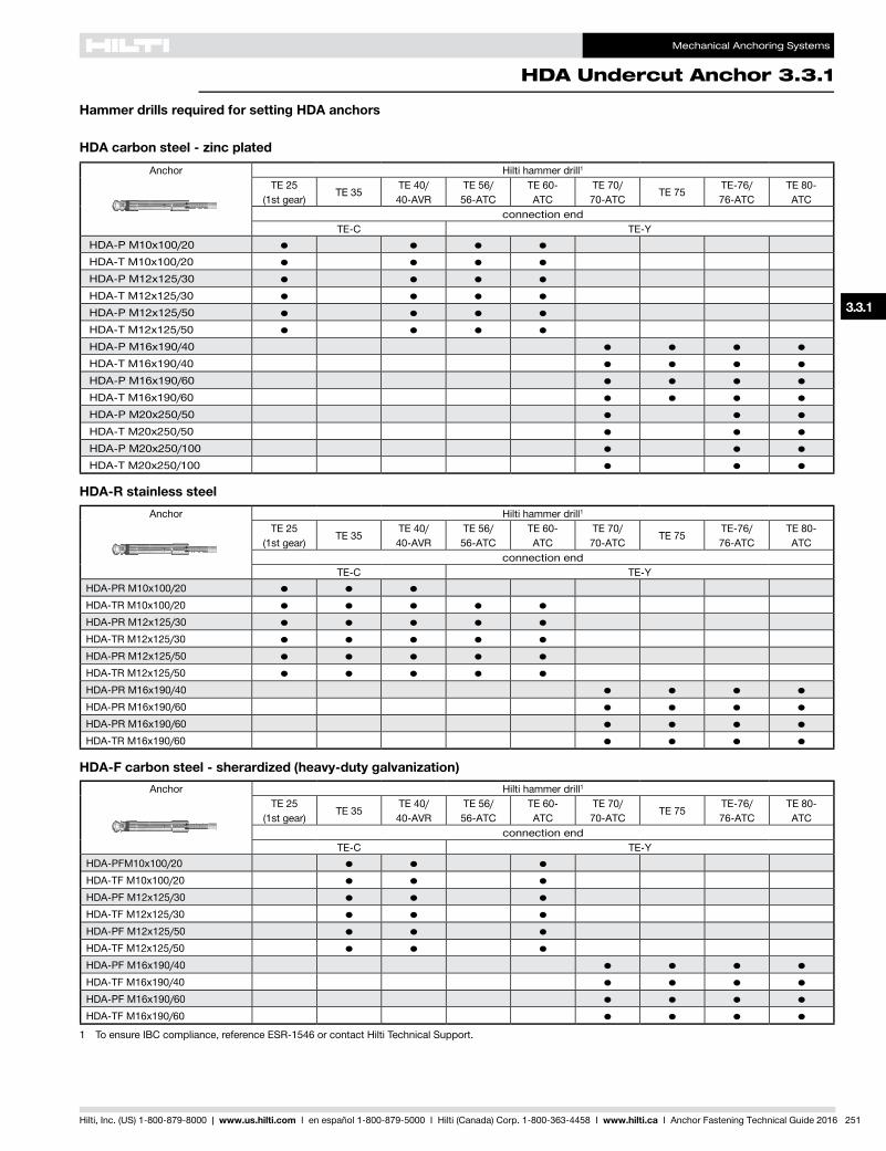
Hammer drills required for setting HDA anchors
Anchor Hilti hammer drill1
TE 25(1st gear)
TE 35TE 40/40-AVR
TE 56/56-ATC
TE 60-ATC
TE 70/70-ATC
TE 75TE-76/76-ATC
TE 80-ATC
connection endTE-C TE-Y
HDA-P M10x100/20 ● ● ● ● HDA-T M10x100/20 ● ● ● ● HDA-P M12x125/30 ● ● ● ● HDA-T M12x125/30 ● ● ● ● HDA-P M12x125/50 ● ● ● ● HDA-T M12x125/50 ● ● ● ● HDA-P M16x190/40 ● ● ● ● HDA-T M16x190/40 ● ● ● ● HDA-P M16x190/60 ● ● ● ● HDA-T M16x190/60 ● ● ● ● HDA-P M20x250/50 ● ● ● HDA-T M20x250/50 ● ● ● HDA-P M20x250/100 ● ● ● HDA-T M20x250/100 ● ● ●
HDA carbon steel - zinc plated
Anchor Hilti hammer drill1
TE 25(1st gear)
TE 35TE 40/40-AVR
TE 56/56-ATC
TE 60-ATC
TE 70/70-ATC
TE 75TE-76/76-ATC
TE 80-ATC
connection endTE-C TE-Y
HDA-PR M10x100/20 ● ● ●HDA-TR M10x100/20 ● ● ● ● ●HDA-PR M12x125/30 ● ● ● ● ●HDA-TR M12x125/30 ● ● ● ● ●HDA-PR M12x125/50 ● ● ● ● ●HDA-TR M12x125/50 ● ● ● ● ●HDA-PR M16x190/40 ● ● ● ●HDA-PR M16x190/60 ● ● ● ●HDA-PR M16x190/60 ● ● ● ●HDA-TR M16x190/60 ● ● ● ●
HDA-R stainless steel
Anchor Hilti hammer drill1
TE 25(1st gear)
TE 35TE 40/40-AVR
TE 56/56-ATC
TE 60-ATC
TE 70/70-ATC
TE 75TE-76/76-ATC
TE 80-ATC
connection endTE-C TE-Y
HDA-PFM10x100/20 ● ● ●HDA-TF M10x100/20 ● ● ●HDA-PF M12x125/30 ● ● ●HDA-TF M12x125/30 ● ● ●HDA-PF M12x125/50 ● ● ●HDA-TF M12x125/50 ● ● ●HDA-PF M16x190/40 ● ● ● ●HDA-TF M16x190/40 ● ● ● ●HDA-PF M16x190/60 ● ● ● ●HDA-TF M16x190/60 ● ● ● ●
HDA-F carbon steel - sherardized (heavy-duty galvanization)
1 To ensure IBC compliance, reference ESR-1546 or contact Hilti Technical Support.