hioki cc30100x current probe manual - national instruments
TRANSCRIPT

INSTRUCTION MANUAL


Contents
Introduction i
Inspection i
Notes on Safety i
Precautions v
Chapter 1 Overview 11.1 Product Overview 1
1.2 Features 1
1.3 Names of Parts 2
1.4 Parts of the Sensor 2
Chapter 2 Specifications 52.1 Product Specifications 5
2.2 Standards Applying 7
Chapter 3 Measurement Procedure 93.1 Notes on Use 9
3.2 Preparations for Measurement 13
3.3 Demagnetizing and Zero Adjustment 14
3.4 Measurement Procedure 17


i―――――――――――――――――――――――――――
Introduction――――――――――――――――――――――――
WARNING
This deviceis designed to comply with IEC 61010Safety Standards, and has been thoroughly testedfor safety prior to shipment. However,mishandling during use could result in injury ordeath, as well as damage to the device. Be certainthat you understand the instructions andprecautions in the manual before use. Wedisclaim any responsibility for accidents orinjuries not resulting directly from device defects.
Introduction
Inspection
Notes on Safety
Thank you for purchasing the HIOKI 3276 CLAMPON PROBE. To obtain maximum performance fromthe device, please read this manual first, and keep ithandy for future reference.
When you receive the device, inspect it carefully toensure that no damage occurred during shipping. Ifdamage is evident, or if it fails to operate accordingto the specifications, contact your dealer or Hiokirepresentative.
Supplied accessoriesInstruction manual 1Carrying case 1

ii―――――――――――――――――――――――――――
Notes on Safety――――――――――――――――――――――――
The symbol printed on the deviceindicates that the user should refer to acorresponding topic in the manual (markedwith the symbol) before using therelevant function.In the manual, the symbol indicatesparticularly important information that theuser should read before using the device.
Indicates that application around orremoval from live lines is only permitted oncondition that the lines are insulated.
Safety SymbolsThis manual contains information and warningsessential for safe operation of the device and formaintaining it in safe operating condition. Beforeusing the device, be sure to carefully read thefollowing safety notes.

iii―――――――――――――――――――――――――――
Notes on Safety――――――――――――――――――――――――
DANGER
Indicates that incorrect operationpresents an extreme hazard that couldresult in serious injury or death to theuser.
WARNING
Indicates that incorrect operationpresents a significant hazard that couldresult in serious injury or death to theuser.
CAUTION
Indicates that incorrect operationpresents a possibility of injury to the useror damage to the device.
NOTEIndicates advisory items related toperformance or correct operation of thedevice.
The following symbols in this manual indicate therelative importance of cautions and warnings.

iv―――――――――――――――――――――――――――
Notes on Safety――――――――――――――――――――――――
Measurement categories (Overvoltagecategories)This device conforms to the safety requirements forCAT I measurement instruments.To ensure safe operation of measurementinstruments, IEC 61010 establishes safety standardsfor various electrical environments, categorized asCAT I to CAT IV, and called measurementcategories. These are defined as follows.CAT I :Secondary electrical circuits connected to
an AC electrical outlet through atransformer or similar device.
CAT II :Primary electrical circuits in equipmentconnected to an AC electrical outlet by apower cord (portable tools, householdappliances, etc.)
CAT III:Primary electrical circuits of heavyequipment (fixed installations) connecteddirectly to the distribution panel, andfeeders from the distribution panel tooutlets.
CAT IV:The circuit from the service drop to theservice entrance, and to the power meterand primary overcurrent protection device(distribution panel).
Higher-numbered categories correspond to electricalenvironments with greater momentary energy, so ameasurement instrument designed for CAT IIIenvironments can endure greater momentary energythan one designed for CAT II. Using a measurementinstrument in an environment designated with ahigher-numbered category than that for which theinstrument is rated could result in a severe accident,and must be carefully avoided.Never use a CAT I measuring instrument in CAT II,III, or IV environments.

v―――――――――――――――――――――――――――
Precautions――――――――――――――――――――――――
Precautions
The measurement categories comply with theOvervoltage Categories of the IEC60664 Standards.
Follow these precautions to ensure safe operationand to obtain the full benefits of the variousfunctions.
Preliminary CheckBefore using the device the first time, verify that itoperates normally to ensure that the no damageoccurred during storage or shipping. If you find anydamage, contact your dealer or Hioki representative.

vi―――――――――――――――――――――――――――
Precautions――――――――――――――――――――――――
DANGER
To avoid short circuits and potentially life-threatening hazards, never attach the 3276 to acircuit that operates at more than 300V, or overbare conductors.When conductors being measured carry inexcess of the safe voltage level (SELV-E) andnot more than 300 V, to prevent short circuitsand electric shock while the core section isopen, make sure that conductors to bemeasured are insulated with materialconforming to (1) Measurement Category , (2)Basic Insulation Requirements for WorkingVoltages of 300 V, and (3) Pollution Degree 2.For safeties sake, never use this sensor onbare conductors. The core and shield case arenot insulated.
Un-insulated
(core and
shield case)

vii―――――――――――――――――――――――――――
Precautions――――――――――――――――――――――――
DANGER
Be careful to avoid damaging the insulationsurface while taking measurements.This instrument is made for use with the 3272POWER SUPPLY. It is possible to use a powersupply other than the 3272, provided that theconnector and pin assignments match, and thatvoltage and other electrical specifications aresatisfied. In the interest of safety, make surethat the power supply has a protective earthingwith double-insulation construction.Make sure that the waveform measuringequipment connected to this device's outputterminal (BNC) is equipped with a protectiveearthing with double-insulation construction.If the waveform measuring instrument beingconnected to the output terminal (BNC) on thisdevice is equipped with any other measurementterminals, take the following precautions toensure that the other instrument does not forma bridge between the probe and any hazardouslive of a part.1. Isolate the terminal to which the probe is
connected from other terminals on themeasuring instrument using basic insulationconforming to the measurement category,working voltage, and pollution degreerequirements of the circuit being tested.

viii―――――――――――――――――――――――――――
Precautions――――――――――――――――――――――――
DANGER
2. If basic insulation requirements cannot bemet between the terminal to which this deviceis connected and other terminals of themeasuring instrument, make sure that thevoltage input to the measurement terminaldoes not exceed the safe voltage level (SELV-E).
3. Read and observe all warnings andprecautions relating to electrical safety for themeasuring instrument being connected to theprobe.
Refer to the following standards regarding themeanings of underlined terms.
IEC61010-1IEC61010-031IEC61010-2-032

ix―――――――――――――――――――――――――――
Precautions――――――――――――――――――――――――
DANGER
Be sure to observe all operating precautions forthe waveform monitoring instrument(oscilloscope or recorder) and othermeasurement instruments to which this deviceis connected.When using a measurement instrument thatdoes not provide isolation between its inputterminals and chassis or other input terminals,please pay attention to the following points.If a signal is applied to an input terminal otherthan that to which this device is connected, donot connect the ground-side terminal to anynon-ground potential. Otherwise, short-circuitcurrent will flow through the 3272 or this devicefrom the ground terminal, which could cause anelectrical accident or damage.
x―――――――――――――――――――――――――――
Precautions――――――――――――――――――――――――
WARNING
Do not allow the device to get wet, and do nottake measurements with wet hands. This maycause an electric shock.To avoid electric shock when measuring livelines, wear appropriate protective gear, such asinsulated rubber gloves, boots and a safetyhelmet.
CAUTION
To avoid damage to the device, protect it fromphysical shock when transporting and handling. Beespecially careful to avoid physical shock fromdropping.This device should be installed and operatedindoors only, between 0 and 40 (32 to 104 )and 80% RH or less.Do not store or use the device where it could beexposed to direct sunlight, high temperature orhumidity, or condensation. Under such conditions,the device may be damaged and insulation maydeteriorate so that it no longer meetsspecifications.This device is not designed to be entirely water- ordust-proof. To avoid damage, do not use it in a wetor dusty environment.

xi―――――――――――――――――――――――――――
Precautions――――――――――――――――――――――――
CAUTION
The sensor head is a precision assembly includinga molded component, a ferrite core, and a Halleffect element. It may be damaged if subjected tosudden changes in ambient temperature, ormechanical strain or shock, and therefore greatcare should be exercised in handling it.The matching surfaces of the sensor head areprecisely ground, and should be treated with care.If these surfaces are scratched, performance maybe impaired.Measurements are degraded by dirt on the matingsurfaces of the sensor head, so keep the surfacesclean by gently wiping with a soft cloth.To avoid damaging the sensor cables, do not bendor pull the sensor cable and power supply cable.To clean the device, wipe it gently with a soft clothmoistened with water or mild detergent. Never usesolvents such as benzene, alcohol, acetone, ether,ketones, thinners or gasoline, as they can deformand discolor the case.When the power is on, keep the core section of thesensor closed, except when clamping them ontothe conductor to be measured. The facing surfaceof the core section can be scratched while it isopen.Keep the clamp jaws and core slits free fromforeign objects, which could interfere with clampingaction.

xii―――――――――――――――――――――――――――
Precautions――――――――――――――――――――――――
CAUTION
Keep the sensor head closed when not in use, toavoid accumulating dust or dirt on the mating coresurfaces, which could interfere with clampperformance.Avoid stepping on or pinching the cable, whichcould damage the cable insulation.Keep the cables well away from heat sources, asbare conductors could be exposed if the insulationmelts.
NOTECorrect measurement may be impossible in thepresence of strong magnetic fields, such as neartransformers and high-current conductors, or in thepresence of strong electromagnetic fields such asnear radio transmitters.
ServiceWhen sending the device for repair, carefully toprevent damage in transit. Include cushioningmaterial so the instrument cannot move within thepackage. Be sure to include details of the problem.Hioki cannot be responsible for damage that occursduring shipment.

1―――――――――――――――――――――――――――
Chapter 1 Overview――――――――――――――――――――――――
Chapter 1Overview
1.1 Product Overview
1.2 Features
This device can be directly connected to a BNCinput connector of a waveform measuringinstrument such as an oscilloscope or recorder, andby clamping on a conductor to be measured, allowsthe current waveform to be easily captured.
Highly accurate current detectionEasy current measurementBroadband frequency characteristics DC to 100MHzCompact and permits measurement of lowcurrent levelsEasy protect function at excessive inputUnique HIOKI development of thin film Halleffect element

2―――――――――――――――――――――――――――
Chapter 1 Overview――――――――――――――――――――――――
3
6
7
4
5
1
2
Current directionindication
Sensor cable
Sensor Terminator
"UNLOCK" indication
Power supplycable
Protectivebarrier
1
2
1.3 Names of Parts
1.4 Parts of the Sensor
External view
Opening leverOperating lever for opening the sensor head. Alwaysuse this lever to open the sensor head.Sensor headThis clamps the conductor being measured, andcarries out the actual current measurement. It is aprecision assembly including a molded component, aferrite core, and a Hall effect element. It may bedamaged if subjected to sudden changes in ambienttemperature, or mechanical strain or shock, andtherefore great care should be exercised in handlingit.

3―――――――――――――――――――――――――――
Chapter 1 Overview――――――――――――――――――――――――
3
4
5
6
NOTE
Demagnetizing switch (DEMAG)This demagnetizes the core if it has been magnetizedby switching the power on and off, or by anexcessive input. Always carry out demagnetizingbefore measurement.The demagnetizing process takes about one second.During demagnetizing, a demagnetizing waveform isoutput.Zero adjustment dial (ZERO ADJ)Use the zero adjustment dial to correct for the effectof a voltage offset or temperature drift on the device.When beginning measurement, after demagnetizingalways carry out zero adjustment.Coarse adjustment trimmerUse this only when adjustment is not possible withinthe range of the zero adjustment dial.Use anonconductive screwdriver (e.g. ceramic driver) foradjustment.Output connectorThe current waveform of the measured conductor isoutput at a constant rate (0.1 V/A).Connect to the BNC input connector of thewaveform measuring instrument.
The output of this device is terminated internally.Use a high-impedance input to the measuringinstrument. With an input impedance of 50Ω,accurate measurement is not possible.If using BNC-banana plug adapters or similar toconnect to input terminals other than BNCconnectors, make sure the polarity is correct.Turn the collar until it clicks, and check that it islocked securely.

4―――――――――――――――――――――――――――
Chapter 1 Overview――――――――――――――――――――――――
7
DANGER
To avoid electric shock, do not touch the portionbeyond the protective barrier during use.
Power plugConnect this to the 3272 POWER SUPPLYreceptacle to supply power to the sensor terminator.

5―――――――――――――――――――――――――――
Chapter 2 Specifications――――――――――――――――――――――――
Frequencyrange
DC to 100 MHz (-3 dB) (Characteristicsshown in Fig. 1)
Rise time 3.5 ns or less
Maximumcontinuous inputrange
30 Arms(Derating according to frequency shownin Fig. 2)
Maximum peakcurrent value
Non-continuous 50 A peak
Output voltagerate
0.1 V/A
Amplitudeaccuracy
1.0% rdg. 1 mV ; to 30 Arms2.0% rdg. ; to 50 A peak
(DC, and 45 to 66 Hz, input withincontinuous maximum input range)
Noise Equivalent to 2.5 mArms or less (for 20MHz band measuring instrument)
Input impedance (Characteristics shown in Fig.3)
Temperaturecoefficient forsensitivity
2% or less (During input of 50 Hz 30Arms within range of 0 to 40 (32 to104 ))
Chapter 2Specifications
2.1 Product SpecificationsAccuracy is guaranteed at 23 5 (73 9 )after the power has been on for 30 minutes.

6―――――――――――――――――――――――――――
Chapter 2 Specifications――――――――――――――――――――――――
Maximum ratedpower
5.3 VA
Rated supplyvoltage
12 V 0.5 V
Operatingtemperature andhumidity range
0 to 40 (32 to 104 ), 80 % RH orless (no condensation)
Storagetemperature andhumidity range
-10 to 50 (14 to 122 ), 80 % RH orless (no condensation)
Location for use Indoor, altitude up to 2000 m (6562 feet)
Effect ofexternalmagnetic fields
Equivalent to a maximum of 5 mA(DC and 60 Hz, Magnetic field of 400A/m)
Maximum ratedvoltage
300 V, CAT Ⅰ(insulated conductor)
Diameter ofmeasurableconductors
5 mm dia.0.2" dia.
Guaranteedaccuracy period
1 year(Opening/closing up to 10,000 times)
Cable lengths Sensor cable Approx. 1.5 m (59.0")Power supply cable Approx. 1 m (39.4")
Externaldimensions
SensorApprox. 175W×18H×40DmmApprox. 6.89"W×0.71"H×1.58"D(excluding protrusions)TerminatorApprox. 27H×55W×18D mmApprox. 1.06"W×2.17"H×0.71"D

7―――――――――――――――――――――――――――
Chapter 2 Specifications――――――――――――――――――――――――
Mass Approx. 240 gApprox. 8.5 oz.
Accessories Instruction manual, Carrying case
Safety EN61010-2-032:2002Measurement categoryⅠ(anticipated transientovervoltage 1500 V), Pollution Degree 2
EMC EN61326:1997+A1:1998+A2:2001+A3:2003
Fig.1 Frequency characteristics(Typical characteristics)
-60
-50
-40
-30
-20
-10
1 100 10k 1M 100MFrequency [Hz]
2.2 Standards Applying

8―――――――――――――――――――――――――――
Chapter 2 Specifications――――――――――――――――――――――――
Fig.2 Derating according to frequency
Fig.3 Input impedance (Typical characteristics)
5
10
15
20
25
30
35
10 100 1k 10k 100k 1M 10M 100M
Frequency [Hz]
1m
10m
100m
1
10
100 1k 10k 100k 1M 10M 100M
Frequency [Hz]

9―――――――――――――――――――――――――――
Chapter 3 Measurement Procedure――――――――――――――――――――――――
DANGER
To avoid short circuits and potentially life-threatening hazards, never attach the 3276 to acircuit that operates at more than 300V, or overbare conductors.When conductors being measured carry inexcess of the safe voltage level (SELV-E) andnot more than 300 V, to prevent short circuitsand electric shock while the core section isopen, make sure that conductors to bemeasured are insulated with materialconforming to (1) Measurement Category , (2)Basic Insulation Requirements for WorkingVoltages of 300 V, and (3) Pollution Degree 2.For safeties sake, never use this sensor onbare conductors. The core and shield case arenot insulated.Be careful to avoid damaging the insulationsurface while taking measurements.
Chapter 3Measurement
Procedure
3.1 Notes on Use

10―――――――――――――――――――――――――――
Chapter 3 Measurement Procedure――――――――――――――――――――――――
DANGER
This instrument is made for use with the 3272POWER SUPPLY. It is possible to use a powersupply other than the 3272, provided that theconnector and pin assignments match, and thatvoltage and other electrical specifications aresatisfied. In the interest of safety, make surethat the power supply has a protective earthingwith double-insulation construction.Make sure that the waveform measuringequipment connected to this device's outputterminal (BNC) is equipped with a protectiveearthing with double-insulation construction.If the waveform measuring instrument beingconnected to the output terminal (BNC) on thisdevice is equipped with any other measurementterminals, take the following precautions toensure that the other instrument does not forma bridge between the probe and any hazardouslive of a part.1. Isolate the terminal to which the probe is
connected from other terminals on themeasuring instrument using basic insulationconforming to the easurement category,working voltage, and pollution degreerequirements of the circuit being tested.

11―――――――――――――――――――――――――――
Chapter 3 Measurement Procedure――――――――――――――――――――――――
DANGER
2. If basic insulation requirements cannot bemet between the terminal to which this deviceis connected and other terminals of themeasuring instrument, make sure that thevoltage input to the measurement terminaldoes not exceed the safe voltage level (SELV-E).
3. Read and observe all warnings andprecautions relating to electrical safety for themeasuring instrument being connected to theprobe.
Refer to the following standards regarding themeanings of underlined terms.
IEC61010-1IEC61010-031IEC61010-2-032

12―――――――――――――――――――――――――――
Chapter 3 Measurement Procedure――――――――――――――――――――――――
DANGER
Be sure to observe all operating precautions forthe waveform monitoring instrument(oscilloscope or recorder) and othermeasurement instruments to which this deviceis connectedWhen using a measurement instrument thatdoes not provide isolation between its inputterminals and chassis or other input terminals,please pay attention to the following points.If a signal is applied to an input terminal otherthan that to which this device is connected, donot connect the ground-side terminal to anynon-ground potential. Otherwise, short-circuitcurrent will flow through the 3272 or this devicefrom the ground terminal, which could cause anelectrical accident or damage.

13―――――――――――――――――――――――――――
Chapter 3 Measurement Procedure――――――――――――――――――――――――
NOTE
3.2 Preparations for Measurement
CAUTION
Before turning on the power, make sure that thevoltage of the power supply being used matches thesupply voltage indicated on the rear panel of the3272.
(1) Have the 3272 POWER SUPPLY, and oscilloscopeor recorder for waveform measurement ready.
The output of this device is terminated internally.Use a high-impedance input to the measuringinstrument. With an input impedance of 50Ω,accurate measurement is not possible.
(2) Turn the power switch off and connect the powercord.
(3) Connect the power plug of the 3276 to the powerreceptacle of the 3272.

14―――――――――――――――――――――――――――
Chapter 3 Measurement Procedure――――――――――――――――――――――――
3.3 Demagnetizing and Zero Adjustment
(4) Turn the 3272 power switch on, and check that thefront panel power indicator lights.
(1) With the waveform measurement instrument input atground, adjust the trace to the zero position.
(2) Set the input coupling of the waveform measurementinstrument to DC.

15―――――――――――――――――――――――――――
Chapter 3 Measurement Procedure――――――――――――――――――――――――
CAUTION
When disconnecting the output connector, be sureto release the lock before pulling off the connector.Forcibly pulling the connector without releasing thelock, or pulling on the cable, can damage theterminator.If using BNC-banana plug adapters or similar toconnect to input terminals other than BNCconnectors, make sure the polarity is correct.
(3) Connect the output connector of the 3276 to theinput connector of the waveform measurementinstrument. Turn the collar until it clicks, and checkthat it is locked securely.
16―――――――――――――――――――――――――――
Chapter 3 Measurement Procedure――――――――――――――――――――――――
CAUTION
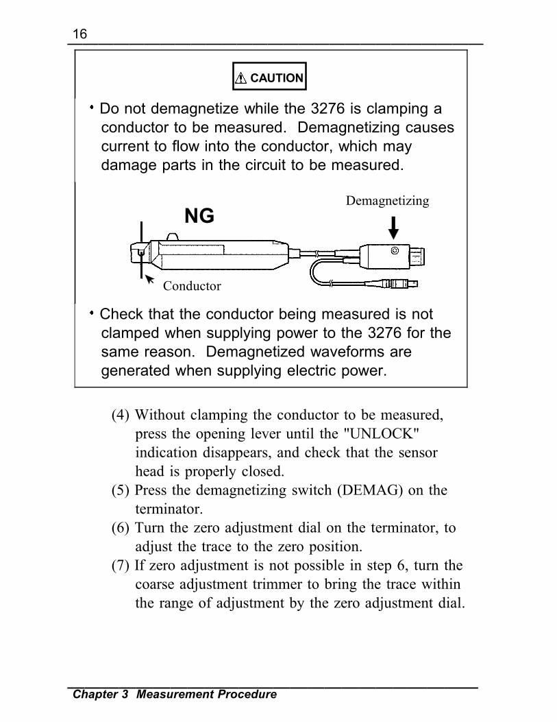
Do not demagnetize while the 3276 is clamping aconductor to be measured. Demagnetizing causescurrent to flow into the conductor, which maydamage parts in the circuit to be measured.
Demagnetizing
Conductor
NG
Check that the conductor being measured is notclamped when supplying power to the 3276 for thesame reason. Demagnetized waveforms aregenerated when supplying electric power.
(4) Without clamping the conductor to be measured,press the opening lever until the "UNLOCK"indication disappears, and check that the sensorhead is properly closed.
(5) Press the demagnetizing switch (DEMAG) on theterminator.
(6) Turn the zero adjustment dial on the terminator, toadjust the trace to the zero position.
(7) If zero adjustment is not possible in step 6, turn thecoarse adjustment trimmer to bring the trace withinthe range of adjustment by the zero adjustment dial.

17―――――――――――――――――――――――――――
Chapter 3 Measurement Procedure――――――――――――――――――――――――
Opening lever
3.4 Measurement Procedure
(1) Check that the system is safe, and that thepreparations described in the preceding section havebeen carried out.
(2) Pull the sensor opening lever, so that the sensorhead opens.
(3) Align the sensor so that the current directionindication corresponds to the direction of currentflow through the conductor to be measured, andclamp so that the conductor is in the center of thesensor aperture.
(4) Press the opening lever on the sensor head until the"UNLOCK" indication disappears, and check thatthe opening lever is firmly locked and the sensorhead securely closed.

18―――――――――――――――――――――――――――
Chapter 3 Measurement Procedure――――――――――――――――――――――――
NOTE
0
100
200
300
400
500
600
0 10 20 30 40 50
AC(f=50Hz)
DC
Current (A)
(5) It is now possible to monitor the current waveform.The output rate of the 3276 is 0.1 V/A. The currentsensitivity can be derived from the voltagesensitivity of the waveform measurement instrument.For example, if the voltage sensitivity is 10mV/division, the current sensitivity is 100mA/division.
When using the 3276, note that two clamp-onprobes may not be used simultaneously with the3272 POWER SUPPLY, depending on the currentto be measured.The current consumption of clamp-on probesdepends on the current to be measured. Confirmthat the total current consumption of the clamp-onprobes does not exceed the rated output current ofthe 3272. See Fig. 1.
Fig.1Current consumption* vs. current to be measured(typical)*The sum total of a positive and negative current consumption

19―――――――――――――――――――――――――――
Chapter 3 Measurement Procedure――――――――――――――――――――――――
WARNING
The maximum continuous input range is basedon heat that is internally generated duringmeasurement. Never input current in excess ofthis level. Exceeding the rated level may resultin damage to the probe.The maximum continuous input range variesaccording to the frequency of the current beingmeasured. See the figures in 2.1, "ProductSpecifications"If excess current is input, generated heatactivates a built-in safety function that blocksnormal output. If this happens, remove theinput immediately (remove the sensor from theconductor being measured, or reduce the inputcurrent to zero). Wait until the sensor has hadsufficient time to cool before resumingoperation.Even if the input current does not exceed therated continuous maximum, continuous inputfor an extended period of time may result inactivation of the safety circuit to preventdamage resulting from heating of the sensor.

20―――――――――――――――――――――――――――
Chapter 3 Measurement Procedure――――――――――――――――――――――――
NOTE
WARNING
At high ambient temperatures, the built-in safetycircuit may activate at current input levelsbelow the rated continuous maximum.Continuous input of current exceeding the ratedmaximum or repeated safety circuit activationwill degrade performance of the safety circuit,possibly resulting in damage to the device.The maximum input range is indicated by thecontinuous maximum input range. It is alsoindicated by another product specificationMaximum peak current: Noncontinuous 50 Apeak. This means that the upper limit of thewaveform response is 50 A peak. Make surethat the input does not exceed the continuousmaximum input range in rms.When opening the sensor head of the probe, besure to operate with the opening lever. If anupper core is forced to open, when the sensorhead is locked, the open-close mechanism canbe damaged.
Do not press Lock stateUpper core
The output of this device is terminated internally.Use a waveform measurement instrument with aninput impedance of at least 1 MΩ.

21―――――――――――――――――――――――――――
Chapter 3 Measurement Procedure――――――――――――――――――――――――
NOTEImmediately after powering on, this device may besubject to an appreciable offset drift due to theeffect of self-heating. To counteract this, allow thedevice to warm up for about 30 minutes beforecarrying out measurement.When performing continuous measurements, it isnecessary to be aware that the offset voltage drifts,depending on factors such as the ambienttemperature.Under certain circumstances, oscillation may occurif the probe is connected to the 3272 POWERSUPPLY while the power supply is on. This doesnot indicate a malfunction. Oscillation can bestopped and operation restored to normal byopening and closing the sensor head.Depending on the measured current frequency,however some sound may be produced byresonance, it has no effect on measurements.The measurement may be affected by the positionwithin the clamp aperture of the conductor beingmeasured. The conductor should be in the center ofthe clamp apertureWhen carrying out measurement, press the openinglever until the "UNLOCK" indication disappears,and check that the sensor head is properly closed. Ifthe sensor head is not properly closed, accuratemeasurement will not be possible.

22―――――――――――――――――――――――――――
Chapter 3 Measurement Procedure――――――――――――――――――――――――
NOTE
Powersource
Load
H
L
NG
OK
At high frequencies, common mode noise mayaffect measurements taken on the high voltage sideof circuits. If this occurs, reduce the frequencyrange of the waveform measuring instrument, orclamp onto the low-voltage side of the circuit, asappropriate.
Accurate measurement may be impossible inlocations subject to strong external magnetic fields,such as transformers and high-current conductors,or in locations subject to strong external electricfields, such as radio transmission equipment.


HIOKI 3276 CLAMP ON PROBE
Instruction Manual
Publication date: September 2006 Revised edition 2
Edited and published by HIOKI E.E. CORPORATIONTechnical Support Section
All inquiries to International Sales and Marketing De-partment81 Koizumi, Ueda, Nagano, 386-1192, JapanTEL: +81-268-28-0562 / FAX: +81-268-28-0568 E-mail: [email protected] http://www.hioki.co.jp/
Printed in Japan 3276A981-02
• All reasonable care has been taken in the production of this manual, but if you find any points which are unclear or in error, please contact your supplier or the International Sales and Marketing Department at HIOKI headquarters.
• In the interests of product development, the contents of this manual are subject to revision without prior notice.
• Unauthorized reproduction or copying of this manual is prohibited.

Printed on recycled paper
3276A981-02 06-09H
HEAD OFFICE81 Koizumi, Ueda, Nagano 386-1192, JapanTEL +81-268-28-0562 / FAX +81-268-28-0568E-mail: [email protected] http://www.hioki.co.jp/
HIOKI USA CORPORATION6 Corporate Drive, Cranbury, NJ 08512, USATEL +1-609-409-9109 / FAX +1-609-409-9108