hipos high intensity positron source at hfr development on
TRANSCRIPT

SCIENTIFIC REPORTSCIENTIFIC REPORTSCIENTIFIC REPORTSCIENTIFIC REPORT
EUR 23662 EN
HIPOS High Intensity Positron Source at HFR DEVELOPMENT ONDEVELOPMENT ONDEVELOPMENT ONDEVELOPMENT ON
High Intensity Positron Sources Digital Positron Lifetime Spectroscopy Advanced Application of Positron Beams Edited by: A.ZEMAN and L.DEBARBERIS

The mission of the JRC is to provide customer-driven scientific and technical support for the conception, development, implementation and monitoring of EU policies. As a service of the European Commission, the JRC functions as a reference centre of science and technology for the Union. Close to the policy-making process, it serves the common interest of the Member States, while being independent of special interests, whether private or national. European Commission Joint Research Centre Contact information Address: P.O. Box 2, NL-1755 ZG Petten E-mail: [email protected] Tel.: +31-224-565467 Fax: +31-224-565636 http://www.jrc.ec.europa.eu Legal Notice Neither the European Commission nor any person acting on behalf of the Commission is responsible for the use which might be made of this publication. A great deal of additional information on the European Union is available on the Internet. It can be accessed through the Europa server http://europa.eu/ Institute for Energy JRC49224 EUR 23662 EN ISSN 1018-5593 Luxembourg: Office for Official Publications of the European Communities © European Communities, 2009 Reproduction is authorised provided the source is acknowledged Printed in the Netherlands

Zeman et al. - Exploratory research on High Intensity Positron Source at HFR Petten (2007) SCIENTIFIC REPORT
Page 3 of 77
PREFACE Since the application of positron beams in fundamental science and applied research, as well as energy related domains, with various range of spectrum from relativistic (Linear Colliders up to 30 GeV) to ultra-cold range (Slow positron beams ~meV) is very novel, further investigation of their applicability in JRC-IE Petten has been evaluated in this study. The AMES group, Nuclear Design Safety unit has engaged in the Exploratory Research Project (ERP) related to this ambitious design of such a kind of innovative facility. The feasibility study of the positron source and its implementation is assessed in this report. The ERP called High Intensity Positron Beam at HFR Petten (HIPOS) has been officially launched in September 2005. Afterwards the project was running for 2 years with its final evaluation of feasibility phase in September 2007. The HIPOS project was dealing with design and development of following sub-areas: 1. High Intensity Positron Sources 2. Digital Positron Lifetime Spectroscopy 3. Advanced Application of Positron Technology The HIPOS can make available the new methods for investigation and testing based on annihilation phenomenon of an intense beam of positron at level > 1010 e+/s. Such methods will be capable to cope with future challenges in many scientific fields, in particular, biotechnology, medicine, space, nanotechnology and material science. The beams available today are limited and due to fundamental reasons an image of defects at nanometer resolution by the present generation of micro-beams is impossible. Therefore, the novel advanced dual micro-beam systems are under design, where the defects are stained with previous positron systems. Then a scanned electron beam with nanometer spot size sensitive to the stained defects will be possible. However, for such facility a very high intensity positron source is required. The HIPOS facility could logically complement the other neutron-based instrumentations, which are developed at the HFR; including SANS, n-scattering and existing positron laboratory. The project can contribute by its outcomes also to the scientific development of the existing JRC-IE actions. It is also on the interest of the JRC, as leading EU research institute, to introduce and develop a scintillating method, which will support investigation pan-European research activities. The R&D of High Intensity POsitron Source (HIPOS), which is to be fed by neutrons and gammas produced by the Petten’s High Flux Reactor (HFR) is explored. The HIPOS ERP has been carried out by JRC-IE directly, however some partial sub-tasks have been subcontracted due to limited internal resources (MCNP calculations – NRG, development of software for advanced digital lifetime spectroscopy – STU Bratislava). The scientific importance of the HIPOS project was also demonstrated by the success that the initiative of JRC-IE which promoted an International Scientific Workshop in North Holland (Bergen), 17-18. November 2005. The most experienced European and also Non-European scientists attended and contributed to this scientific event; including: Helsinki University of Technology (Finland); Delft University of Technology (Netherlands); Slovak University of Technology (Slovakia), Charles University (Czech Republic), University of Bundeswehr (Germany), University Halle (Germany), SCK-Mol (Belgium), NRG (Netherlands) and Institute of Theoretical and Experimental Physics (Russia). The proceeding has been published by EUR 22182 EN report (2006).
Andrej ZEMAN (editor)

Zeman et al. - Exploratory research on High Intensity Positron Source at HFR Petten (2007) SCIENTIFIC REPORT
Page 4 of 77
ABBREVIATIONS ACAR Angular Correlation of Annihilation Radiation ADC Analogue Digital Converter AMOC Age-MOmentum Correlation positron technique BEC Bose-Einstein Condensate CFD Constant Fraction Discriminator CSPM Cryogenic Solid Positron Moderator DBS Doppler Broadening Spectroscopy EC European Commission EPR Exploratory Research Project FWHM Full Width in Half Maximum GS Giga Sampling HEU High Enriched Uranium HFR High Flux Reactor HIPOS High Intensity Positron Source POSH Positron Source ay HOR reactor Delft IAEA International Atomic Energy Agency IE Institute for Energy JRC Joint Research Centre LEPD Low Energy Positron Diffraction LEU Low Enriched Uranium LINAC Linear Accelerator MCNP Monte Carlo transportation code MOC Mid of Cycle NEPOMUC Neutron Positron Source Munich NRG Nuclear Research Group Petten PAS Positron Annihilation Spectroscopy PAES Positron Auger Electron Spectroscopy PALS Positron Annihilation Lifetime Spectroscopy PLEPS Pulsing Low Energy Positron System PRS Pneumatic Rabit System R&D Research and Development REPELS Reemitted Positron Energy-Loss Spectroscopy RF Radio Frequency RG Relevance Gap RPS Re-emitted Positron / Positronium Spectroscopy SANS Small Angle Neutron Scattering SPB Slow Positron Beam SPM Scanning Positron Microscopy STU Slovak Technical University TEM Transmission Electron Microscopy Å Angstrom β+ Beta plus decay e+ positron e- electron γ gamma (photon) Z atomic number
Zeman et al. - Exploratory research on High Intensity Positron Source at HFR Petten (2007) SCIENTIFIC REPORT
Page 5 of 77
CONTENT
Preface 3
Abbreviations 4
Content 5
Introduction 6
1. HIPOS - deliverables and objectives 10
2. High intensity positron sources 12
3. Positron beams 22
4. HIPOS pre-design 27
5. HFR source definition 32
6. Experimental validation of MCNP outcomes 38
7. HIPOS computer calculations 43
8. HIPOS design optimization 49
9. Design finalisation 56
10. Digital Lifetime spectroscopy 62
11. Advanced applications of positron technology 68
References 75

Zeman et al. - Exploratory research on High Intensity Positron Source at HFR Petten (2007) SCIENTIFIC REPORT
Page 6 of 77
INTRODUCTION With the wide-expansion of positron annihilation techniques into the various research fields there is a strong demand for high intensity positron sources, which are required for effective utilization of advanced beam systems. There are many efforts made, throughout the world, to design and set-up positron sources and beam systems with high intensity based on various principles. Such a positron source could be the basis for a series of experiments in fundamental and applied research and would also be a prototype source for industrial applications, which can concern not only in the field of matter characterization at the nanometer scale. Phenomena involving positrons are important in many fields of applied science, as medicine, biology, physics, energy, etc. The laboratories with low-energy positron beams are now being also used for investigation of outstanding studies of electron–positron plasma phenomena, anti-hydrogen formation, modeling of astrophysical processes, and just recently also for newly discovered Bose-Einstein condensate. However, the limitations of such studies are often due to the relative lack of suitable positron sources. Therefore, the key-outcomes of the HIPOS project include the basic design & development of such powerful experimental facility with a very high intensity positron source based on reactor source. Proposed concept utilize a (n,γ) and (γ, pair) nuclear reactions within designed positron generator at High Flux Reactor (HFR) in Petten. This document summarizes the advanced application of such intense positron beams, in particular Slow Positron Beams (SPB), Pulsing Low Energy Positron System (PLEPS) and positron microscopy (PM). A brief overview of the new challenges in broad-range research is given within the areas of scientific applications, from biology to space-applications and fundamental physics. The HIPOS was leaded by JRC-IE scientists, however other partners have been involved in some sub-tasks as external contributions, in particular: NRG (The Netherlands) and Slovak University of Technology (Slovakia). The present document is the final one of a series of reports summarizing the results of the HIPOS project. The complete list of the titles and contributors is as follows:
(i) HIPOS exploratory research A.Zeman (JRC), L.Debarberis (JRC) (ii) Positron sources A.Zeman (JRC) (iii) Positron beams A.Zeman (JRC), V.Slugeň (STU) (iv) HIPOS pre-design A.Zeman (JRC) (v) HFR source definition A.Hogenbirk (NRG) (vi) Experimental validation of HB9 source A.Hogenbirk (NRG) (vii) HIPOS computer calculations K.Tuček (JRC), G.Daquino (JRC) (viii) HIPOS design optimization K.Tuček (JRC), A.Zeman (JRC) (ix) Design finalization A.Zeman (JRC) (x) Digital positron lifetime spectroscopy M.Petriska (JRC), A.Zeman (JRC) (xi) Advanced applications of positron technology A.Zeman (JRC) (xii) HIPOS summary A.Zeman (JRC)

Zeman et al. - Exploratory research on High Intensity Positron Source at HFR Petten (2007) SCIENTIFIC REPORT
Page 7 of 77
Biographical notes of all contributors to HIPOS project are summarised shortly. Andrej Zeman received his MSc (1997) and a PhD (2003) at the Slovak University of Technology, Bratislava. He is a Research Scientist at the Joint Research Centre of the EC. The main domains of his interest are advanced applications of high-intensity neutron beams, study of micro-structural properties by Non-Destructive-Techniques (NDT), investigation of radiation induced degradation mechanisms and contribution to understanding of microstructural changes to structural integrity of nuclear power plant pressurised components. He is an author or co-author of about 50 original papers in scientific journals or at the international conferences. Luigi Debarberis is the Project Leader of the SAFELIFE Action within the Joint Research Centre of the European Commission. He has a PhD and has been active for the past 20 years in the field of understanding, assessing and modelling of radiation embrittlement and materials degradation with more than a hundred papers published on peer-reviewed journals and international conferences. He is an honorary member of the Hungarian Academy of Engineering, member of the PERFECT I.P. Governing Board, IGRM and Advisory Board Member of PSI. Kamil Tuček received his MSc in Nuclear Engineering from the Czech Technical University in Prague (1996) and a PhD in Physics from the Royal Institute of Technology (KTH) in Stockholm, Sweden (2004). He is currently researcher at the Joint Research Centre, Institute for Energy in Petten, the Netherlands analyzing feasibility and safety aspects of Generation-IV systems. His main research interests are neutronic and severe safety aspects of fast reactor designs (lead-cooled, sodium-cooled, and gas-cooled fast reactors), optimization of reactor core designs for breeding and waste burning, and application and development of Monte Carlo neutronic and burn-up codes. He has authored or co-authored more than 30 papers in peer-reviewed scientific journals and at the international conferences or workshops. Giuseppe G. Daquino received his MSc in Nuclear Engineering in 1997 at the University of Pisa (Italy). He received his PhD in Nuclear and Industrial Safety at the same University in collaboration with the Joint Research Centre (JRC) of the EC in 2003. He worked at CERN (Geneva, Switzerland) in the domain of the background radiation studies related to the LHCb detector. He is now a Research Scientist at the JRC (Institute for Energy, Petten, NL). His main fields of research are related to radiation dosimetry and metrology, Monte Carlo simulation of transport of neutral and charged particles in matter, safety systems. He is author or co-author of more than 50 papers in peer-reviewed journals or published in international conferences proceedings. He is member of ISNCT (International Society of Neutron Capture Therapy), Italian Engineering Association, IAEA, EU Framework Programme expert and ECS (Expert Communication System) at CTBTO He is member of the ICNCT Society and Italian Engineering Association. Vladimír Slugeň graduated in 1985 from the Faculty of Electrical Engineering and Information Technology, Slovak Technical University Bratislava (FEI STU), in nuclear power engineering. He gained his PhD from the FEI STU in 1993 and became an Associate Professor at the Department of Nuclear Physics and Technology in Nuclear Power Engineering (1998). His main field of research and teaching activities is operation and safety of nuclear power plants, application of spectroscopic methods by investigation of materials used in nuclear industry (about 100 original papers in scientific journals or at the international conferences). Martin Petriska graduated from the Faculty of Electrical Engineering in 1994 with specialisation in radio electronics. Since 2002 he has been a research worker at the Department of Nuclear Physics and Technology, FEI STU. His main field of research activities is electronics for the positron annihilation lifetime measurements, and C++ programming for digital lifetime measurement set-up. Alfred Hogenbirk is responsible for Monte Carlo neutronics simulations at NRG Petten. He received his MSc

Zeman et al. - Exploratory research on High Intensity Positron Source at HFR Petten (2007) SCIENTIFIC REPORT
Page 8 of 77
in 1985 at the Free University in Amsterdam in Experimental Nuclear Physics. In 1989 he received his PhD at the same university. He has been active in a broad field, including the evaluation and processing of nuclear data, the simulation of radiation damage, fusion neutronics simulations, sensitivity and uncertainty studies and depletion calculations. He was involved in several projects related to the improvement of neutronics simulations for the Petten High Flux Reactor.

Zeman et al. - Exploratory research on High Intensity Positron Source at HFR Petten (2007) SCIENTIFIC REPORT
Page 9 of 77
Chapter (i) HIPOS EXPLORATORY RESEARCH
by A.ZEMAN and L.DEBARBERIS

Zeman et al. - Exploratory research on High Intensity Positron Source at HFR Petten (2007) SCIENTIFIC REPORT
Page 10 of 77
1. HIPOS - deliverables and objectives The HIPOS exploratory research was carried out with the aim to complete the postulated deliverables with all particular objectives, as specified below: High Intensity Positron Beam (HIPOS) This particular task includes the simulation, modeling and validation of the performance of (n,γ) reaction and effectiveness of concept for pair production reaction including spectral analysis and design optimisation. The key objective of the HIPOS sub-task was to perform the feasibility study, which includes the demonstration of capability of HFR to achieve very high intensity positron beam. The particular objectives of HIPOS are structured, as follows: - HFR site survey - Pre-design of positron generator - MCNP neutron-gamma source definition - Experimental validation of neutron-gamma source - MCNPX & GEANT4 calculations of positron production - MCNPX calculations for optimization of design/material properties Digital Life-Time spectroscopy (DigiLT) This task incorporated the development of a new digital spectrometer based on an ultra-fast digitizer card which will be an extension of existing on-site positron laboratory of the IE-JRC. The digital processing system will improve capabilities for better understanding of microstructural changes and their characterization by significant increase of resolution and effectiveness of data processing. The particular objectives of Digi_LT contains following parts: - Design of Digital lifetime spectrometer - Development of unique software package - Preliminary benchmarking of new system with existing concepts Advanced application of positron beam techniques Since, electrons reflects the chemical properties in the nature, an advanced techniques based on positrons can be used in different way of applications. Since positrons are very sensitive to the electron density, the positron-based probes can be easily applied for determination of matter properties. A short overview of the available techniques, including possible applications in various research domains, such as, nuclear energy, nanotechnology, space industry, medicine and biology are described briefly. Positron technology can also contribute to understanding some particular phenomenon in basics science, such observation of recently discovered Bose-Einstein Condensate (BEC) and plasma dynamics and many others.

Zeman et al. - Exploratory research on High Intensity Positron Source at HFR Petten (2007) SCIENTIFIC REPORT
Page 11 of 77
Chapter (ii) POSITRON SOURCES
by A.Zeman

Zeman et al. - Exploratory research on High Intensity Positron Source at HFR Petten (2007) SCIENTIFIC REPORT
Page 12 of 77
2. HIGH INTENSITY POSITRON SOURCES
Positron’s history The positron was postulated by Dirac (1930) as “negative” energy extension of his theory of electron energy levels. Andreson’s discovery (1932-1933) followed soon afterwards, and a first antiparticle in the history was physically detected. Since that time the application of positrons has been extended to various domains of science with important consequences. Further development of positron beam techniques offered the generation of mono-energetic gamma radiation. Recent experiments have shown that high energy-positron beams produced by linear-collider can be focused and also create wakes with large accelerating gradients propagate in plasmas. For similar parameters, the wakes driven by positron beams are somewhat smaller compared to the case of an electron beam [1]. In conventional applications of positron annihilation systems the β+ radioisotopes are typically used as a source of positrons. Because the intensity of such positron sources is relatively low (106 e+/s) and their operation is not very reliable, innovative methods for production of high intensity positron sources for advanced beam technology are needed. One of these concepts is based on radiation of nuclear reactor, where the neutron flux can be converted to gamma radiation by means of a capture reaction on cadmium due to its high cross section for the neutron capture reaction. Afterwards, the multiple gammas are released and can be used for pair production. The advantage of this type of source is the formation of a continuous positron beam with very high intensity. Overview of positron sources The successful application of advanced positron techniques is strongly limited by the intensity of the positron source. Only few installations with the high intensity positron sources exist world-wide. Since, the intensity of the positron beam is limiting the areas of future applications it’s very important to supply sufficient intensity of positrons for further experimental purposes. Basically, there are three different concepts of sources for positron beams: (a) Conventional β+ radioisotopes, most common 22Na (half-life of 2.6 y), accidental contamination of
laboratory personnel is less harmful (since the biological half-life is only a few days). In addition, other isotopes can be used, e.g. 64Cu and 58Co or 18F.
(b) Generation of electron–positron pairs by accelerators - high-energy photon radiation is an alternative way
to obtain positrons. Two types of accelerators are suitable for production of positrons, LINACs/Cyclotrones, which are producing high energy gammas via Bremsstrahlung radiation. Furthermore, the Ion accelerators with direct (p, e+) or indirect spallation nuclear reaction (p, n) → (n,γ) → (γ, pair) can be used for production of positrons. However this, concept has several limitations caused by high power density of used beam, in particular the effective cooling of target section is the critical point of whole facility. Moreover, high-activation of the structural material will occur in case of design with spallation source.
(c) Radiation of High-Flux-Reactor’s - neutron and/or photon core radiation can be used for pair-production.
This concept can use also the contribution of thermal neutrons to increase the pair’s yield production via the sequence of nuclear reactions (n,γ) → (γ, pair), typically on cadmium. A critical point for this design is burn-up of (n,γ) converter and the risk for activation of structural material of the positron generator since the system is localised near by reactor-core with the presence of fast neutrons. There are various technical proposals on how-to-make a softening of neutron spectra (e.g re-moderation). Advantages of

Zeman et al. - Exploratory research on High Intensity Positron Source at HFR Petten (2007) SCIENTIFIC REPORT
Page 13 of 77
this concept are the lower power density without special cooling system and thus direct (γ, pair) reaction due to presence of photon radiation from core.
Production of high-energy photons A very effective setup of the high intensity positron source is based on principle of thermal neutron capture on cadmium. This process is completely dominated by the nuclear reaction 113Cd(n,γ)114Cd due to the enormous cross section for thermal neutron capture of 26000 barn of 113Cd. Since, the abundance of 113Cd is 12.22 % in natural cadmium (table 1), a total thermal neutron capture cross section is only 24500 barn. The neutron binding energy of 9.041 MeV is released as γ−radiation, where on an average multiplicity of gamma 2.3 with more than 1.5 MeV per captured neutron are emitted [2].
Table 1 - Natural abundance of Cadmium nuclides [3]
Nuclide 106Cd 108Cd 110Cd 111Cd 112Cd 113Cd 114Cd σ c / b 1 1 0.1 24 2.2 19,820 0.3 Abundance /% 1.25 0.89 12.45 12.80 24.13 12.22 28.37
Figure 1 - Cross Sections of neutron interaction for 113Cd, total, elastic scattering, capture, fision, inelastic from 1.10-2 eV to 20 MeV [4].
Pairs generation Afterwards, high energy photons (E > 1.022 MeV) can be converted to electron-positron pairs via (γ,pair) nuclear reaction schema (figure 2). Thereafter, a nuclear reaction (γ,pair) can be used. Absorption of the high-energy γ−radiation generates positrons by pair production, whose maximum intensity depends on the energy spectrum of gamma radiation (for Cd based source 1 MeV approximately).

Zeman et al. - Exploratory research on High Intensity Positron Source at HFR Petten (2007) SCIENTIFIC REPORT
Page 14 of 77
It is important to note, that the γ → pair conversion should take place in matter with high nuclear charge Z, since the cross section for pair production is approximately proportional to Z2. Therefore only the metals with high density have properties good enough for such applications. Figure 2 – Principle of high-energy gamma production by n-capture reaction on cadmium followed by e+ production in single/poly-crystalline tungsten, platinum or nickel.
The pair production is the dominant interaction process for high-energy photons. Only at low energies (below 10 MeV) the Compton scattering and photoelectric absorption contribute to cross-section parameter. For the calculation of electromagnetic showers, the energy spectrum of the generated positron (electron) can be approximated by [5]:
( ) ( ) ( )
−+−+
≈Φ +
++ 1321, 22
0
vvvvk
dEXdxdxdEkE (2.1)
where: X0 – radiation length E+ - energy of the produced positron k - energy of incident photon dx - thickness of the traversed material
kEv += , (2.2)
This formula is valid for 31
.
−+ >> ZmE e and for k > 10 MeV, where:
me - electron mass Z - atomic number of the traversed material. Than total probability for pair production over a path dx is given by,
∫
≈Φ ++
k
meXdxdEkE09
7),( (2.3) This can be expressed also more simply, the attenuation length due to pair production is 9/7 times the radiation length.
Thermal neutrons
Cadmium plate
Tungsten, platinum or nickel foil
High-energy photons

Zeman et al. - Exploratory research on High Intensity Positron Source at HFR Petten (2007) SCIENTIFIC REPORT
Page 15 of 77
Design aspects Another very important characteristic is an affinity A+ and work function Φ+ of positron. Since, the positron affinity A+ is defined by A+ + Φ− + Φ+ = 0, where Φ− (Φ+) refer to the electron (positron) work functions, is a fundamental property of solids which is useful for the determination of the behaviour of positrons [6]. The positron can only be naturally re-emitted from the surface of the materials with a negative positron work function. Therefore, metals like, tungsten, platinum or nickel (figure 3), have properties good enough for pair-generation combined with re-emission and moderation ability of born positrons. Thickness of the positron generator/moderator has to be maintained according to the energy spectra of positrons generated in the source. Due to basic interactions of gamma radiation and positrons with matter, the compromise between the yield of pair production and efficiency of release of positrons from surface must be taken into account. It is remarkable to note that there is also relatively high contribution of pair production from cadmium itself. Therefore, interface gamma source material (cadmium) and positron generator (tungsten, nickel, platinum…) must not be physically separated.
Table 2 – Modified Mendeleyev table wit h specified positron affinity A+ (eV) for selected elements [7]. Moderation of positrons The termalisation of positrons, called as moderation, is based on the fact that a negative positron work function Φ+ exists for some solids (metals mainly). In most cases, a transmission geometry with a thin moderator foil should be placed close to the source in form of capsule. The thickness of the moderator must be reduced with the respect of the mean penetration depth of positrons and, therefore, only a small fraction of positrons thermalizes and starts to diffuse there. If the surface is reached during the diffusion, the positrons are spontaneously emitted from the moderator foil with a kinetic energy equal to the thermally broadened work function Φ+. Materials with high atomic numbers are favourable for moderation, because the ratio of the mean diffusion length to the thermalization distance is larger. The materials suitable enough for moderation of positrons are particularly, a single-crystal tungsten foil in a (100) orientation with a thickness of a few µm. Since the positrons may be trapped in defects during their diffusion to the surface, a foil containing only a small number of positron traps must be prepared by annealing. The work function of a (110)-oriented tungsten single crystal was measured to be Φ+ = -3.0 eV and a moderation efficiency of 3x10⁻³ could be achieved [8,9]. The moderation efficiency epsilon (∈ ) is given as the ratio of the number of moderated slow positrons to the total number of incident positrons. The low-energy positrons are typically emitted by negative-positron-affinity moderator surfaces irradiated by the positron source. The slow-positron conversion efficiency epsilon (flux of slow positrons/total activity) of a
Li-7.35
Be-3.11
Na-7.12
Mg-6.18
Al-4.41
Si-6.95
K-7.05
Ca-6.40
Sc-5.10
Ti-4.06
V-3.44
Cr-2.62
Mn-3.72
Fe-3.84
Co-4.18
Ni-4.46
Cu-4.81
Zn-5.24
Ge-6.69
Pb-6.98
Sr-6.41
Y-5.31
Zr-3.98
Nb-2.93
Mo-1.92
Tc-1.67
Ru-1.92
Rh-3.10
Pd-5.04
Ag-5.36
Cd-5.78
Sn-7.60
Cs-6.94
Ba-6.13
Lu-4.90
Hf-3.70
Ta-2.69
W-1.31
Re-0.97
Os-0.89
Ir-1.53
Pt-3.36
Au-4.59
Pb-5.56

Zeman et al. - Exploratory research on High Intensity Positron Source at HFR Petten (2007) SCIENTIFIC REPORT
Page 16 of 77
Cu(111) single-crystal moderator increases 30% when the positron affinity is made more negative by exposure of the Cu to H2S in situ. Upon cooling the moderator crystal to 100 K, ∈ increases an additional 50% to 1.5x10⁻³ using a low-self-absorption β+ source in a backscattering geometry [10]. The improved concepts of positron moderators can be used, such a vapor-deposited cryogenic para-hydrogen (pH2) solids. An integral step in every low energy positron production and trapping scheme is the “moderation” or slowing down of the up to ~1 MeV nascent positrons to kinetic energies ~ 1 eV. The best positron moderators currently known are thin cryogenic rare gas solid films; efficiencies of order 0.5% have been demonstrated for solid neon that other 99% of the nascent fast positrons are wasted. Studies on solid rare gas moderators suggest that the crystalline quality of the solid is key to its performance since slow positrons scatter, localize, and annihilate at defects. To the best of our knowledge, solid pH2 has never been investigated as a positron moderator, although hydrogenic solids have been used successfully to moderate energetic muons. The research on the production and spectroscopic characterization of high-quality (large crystalline grained and low defect concentration) vapor-deposited cryogenic pH2 solids is in progress. The estimated moderation efficiency for solid pH2 should be about an order of magnitude higher than solid neon, if positron annihilation at crystallite grain boundaries is actually a major loss mechanism. The performance of rare gas solid positron moderators is observed to deteriorate on a timescale of several hours, probably because of the surface contamination and/or accumulated radiation damage. Thus, very precise monitoring of the pH2 solids condition by using high-resolution infrared absorption spectroscopy during operation is required to establish their initial crystalline quality and to test for subsequent surface contamination and radiation damage, and to evaluate methods for mitigating the impact of these processes on the delivered positron moderation efficiency. This will also attempt to tailor the positron moderation properties of the pH2 solids by deliberately introducing dopant molecules in a controlled fashion to produce functionally graded structures such as “field assisted moderators.” Finally, we will explore possibilities for efficiently producing beams of slow positronium (a bound positron-electron pair) directly in our doped moderators [12]. Recently, new observation of copious positron re-emission from crystalline 6H-SiC, with no pre-treatment and without the need for ultra-high-vacuum conditions, suggests that this material may form the basis of an important new moderator for the production of mono-energetic positrons [13]. The positron work function is measured to be at the level eV. Its electrical characteristics point to SiC as a prime candidate for development as a field-assisted positron moderator, producing moderately intense slow-positron beams in laboratory-based systems and enabling a new generation of positron experimentation. It is important to emphasize that both innovative concepts of positron moderation (pH2 and 6H-SiC) have only limited application in reactor-based positron sources due to very specific operational conditions (radiation field, temperature and nuclear safety aspects)

Zeman et al. - Exploratory research on High Intensity Positron Source at HFR Petten (2007) SCIENTIFIC REPORT
Page 17 of 77
1.E-11
1.E-08
1.E-05
1.E-02
1.E+01
1.E+04
0.001 0.1 10 1000 100000Energy (MeV)
Σ (cm2 /g)
Co her-scattering (cm2/g)Incoher-scattering (cm2/g)Photo-electric absorption (cm2/g)Pair-nucl.field (cm2/g)Pair-elect.field (cm2/g)Total (cm2/g)
A
1.E-11
1.E-08
1.E-05
1.E-02
1.E+01
1.E+04
0.001 0.1 10 1000 100000Energy (MeV)
Σ (c
m2/g)
Co her-scattering (cm2/g)Incoher-scattering (cm2/g)Photo-electric absorption (cm2/g)Pair-nucl.field (cm2/g)Pair-elect.field (cm2/g)Total (cm2/g)
B
1.E-11
1.E-08
1.E-05
1.E-02
1.E+01
1.E+04
0.01 0.1 1 10 100 1000 10000 100000Energy (MeV)
Σ (cm2 /g)
Co her-scattering (cm2/g)Incoher-scattering (cm2/g)Photo-electric absorption (cm2/g)Pair-nucl.field (cm2/g)Pair-elect.field (cm2/g)Total (cm2/g)
C
Figure 3 - Cross-section of photon-pair production for (A) tungsten, (B) platinum and (C) cadmium [13]

Zeman et al. - Exploratory research on High Intensity Positron Source at HFR Petten (2007) SCIENTIFIC REPORT
Page 18 of 77
Reactor based positron source Due to the fact of relatively low moderation efficiency (0.1 % approximately) much stronger positron sources are required for the applications of positron beam techniques. The highest intensities can be achieved only by high-flux-reactor concept due to natural implications. Only two installations based on reactor source concept are available in operation conditions. First facility is called NEPOMUC (figure 4) and is installed at FRM-II reactor of University of Bundeswehr (Germany). This concept includes the positron generator, which converts the thermal neutrons through capture reaction on natural cadmium, which release the high-energy gammas. These photos generate subsequently the electron-positron pairs on platinum. The intensity of the positron generator is foreseen at level 109 e+/s of the slow-energy positrons per second.
Figure 4 – Design of NEPOMUC positron source [2].
The second concept, called POSH (figure 5), is installed at HOR reactor of Delft University (The Netherlands). It is is based purely on (γ, pair) reaction and the final intensity of the positron beam is at the level 108 e+/sec (POSH) , which is one order of magnitude lower than NEPOMUC source.
Figure 5 – Design of POSH positron source [14,15].

Zeman et al. - Exploratory research on High Intensity Positron Source at HFR Petten (2007) SCIENTIFIC REPORT
Page 19 of 77
As was mentioned earlier, only the material with high cross section for pair production can be effectively used for conversion, as tungsten, platinum or nickel. Since, the platinum has slightly higher conversion factor, about 11 % higher than in tungsten, this material can be preferred. On the other hand slightly better stability of tungsten in radiation field is an advantage for this concept. After consideration of all aspects, tungsten was chosen, as a primary material for generation of positrons. The tungsten concept is also applied as positron moderator due to its already confirmed long-term stability under reactor conditions. The aim to produce a higher amount of positrons can be only reached via an increased volume (size) of positron generator. As was described previously, the thin foils enable the thermalized positrons to reach the surface. Taking into account the optimal thickness of about 0.3 – 0.8 mg/cm2 the surface to volume ratio of platinum has to be maximized to enhance the output of moderated positrons. The expected beam intensity seems to relatively high, although it can decrease, due to different reasons, up to one order as found to Delft experiences since 2000 [15]. On the other hand, the energy range seems to be realistic and comparable to other similar devices. The proposed HIPOS positron generator can produce the beam, which is formed by triple-stage stochastic cooling (moderation) of the positrons emitted from a source. A design of the positron collector has been done in order to transport the positrons with the highest possible efficiency to take advantage of this wide angle of production by electrostatic separation. Furthermore, a system with solenoid coil is producing diverging magnetic field lines for magnetic focusing of the beam into extraction beam-line. The magnetic lines are collected by a large diameter coil to form a magnetic bulb. Moreover, such setup would offer the possibility that a conventional scanning electron microprobe for easy alignment of the optical column and for surface analysis can be included into the system quite easily. The combination of electrostatic extraction and magnetic perpendicular focusing is used for HIPOS concept (figure 6).
Figure 6 – Pre-design of HIPOS positron source. Since, HIPOS concept is foreseen, as a advanced instrumentation, which offers HFR in Petten, further study in frame of exploratory research was concentrated to evaluation of reactor parameters and available neutron beams. The layout of the HFR including its instrumentation of horizontal experimental channels (ground-floor) is presented in figure 7. Further details about HFR are summarized in referenced literature [16-18]. The HIPOS will offer further implementation of advanced applications based positron annihilation techniques. Since HFR offers unique opportunity for installation of such novel facility due to outstanding parameters
W H2O Cd

Zeman et al. - Exploratory research on High Intensity Positron Source at HFR Petten (2007) SCIENTIFIC REPORT
Page 20 of 77
further localisation at one of the horizontal neutron beams can give a good chance to find out several useful applications in the investigation of ageing and neutron embrittlement phenomenon of materials for fission and fusion technologies via new information about defects creation and behavior to contribute to nuclear safety of such facilities.
Figure 7 – Layout of HFR ground-floor with the instrumentation of neutron beams [16].

Zeman et al. - Exploratory research on High Intensity Positron Source at HFR Petten (2007) SCIENTIFIC REPORT
Page 21 of 77
Chapter (iii) POSITRON BEAMS
by A.Zeman and V.Slugeň

Zeman et al. - Exploratory research on High Intensity Positron Source at HFR Petten (2007) SCIENTIFIC REPORT
Page 22 of 77
3. Positron beams The experimental problems associated with the efficient production of slow-positron beams have required significant effort to solve. This is demonstrated by the fact that the first published suggestion of the process (Madanski and Rasetti, 1950) predates the “near-theoretical” efficiencies approaching 1%. The development of efficient positron beams is more recent, and the field of surface and near-surface studies with, positrons has evolved only since 90s. The positron beam is typically created by exploiting the phenomenon of the re-emission of slow positrons from solids irradiated by fast positrons from the source. A fraction of the implanted positron diffuse to the exit surface of the material, they are then able to escape into the vacuum as long as there is no surface potential barrier to prevent them from doing so. The enormous increase in the efficiency for slow-positron beam production has led to a commensurate increase, both in number and diversity, of their applications in wide range of scientific studies [19]. Continuous positron beam Beams of positrons are making possible a number of new experiments yielding information about the properties of positron-atom scattering cross sections, the atomic physics of positronium and the surface studies. Therefore there is a great interest in obtaining positron beams of high intensity. The low-energy positrons for such beams are presently obtained by moderating the ~ 106 eV end-point energy β+ spectrum of a suitable radioactive source using a solid surface. The advances in understanding of how low-energy positrons interact with a solid surface have defined clearly the necessary elements of a high-efficiency slow-positron moderator, the result being that one can now extract one part in 103 of the energetic positrons in a < 0.5 eV wide slow positron beam The mono-energetic positron beams are still not commercially available, as in the case of electron beams. Therefore, a significant amount of theoretical and experimental work must be done for exploitation of positron beams and their applications also in the area of positron microscopy. There are foreseen a large number of applications in solid state physics, materials science, chemistry and otherwise, where the positron is clearly the particle of choice over the electron. Positrons are very sensitive probes for vacancy-type defects of atomic dimensions, e.g., vacancies, vacancy agglomerates, voids, dislocations, or inner surfaces. The unavailability of high intensity positron beams has retarded the widespread application of slow positron methods to microscopy and micro-probe problems.
Figure 8 – Design schema of magnetically guided positron beam [19].
0 0.5 1.0 1.5 m

Zeman et al. - Exploratory research on High Intensity Positron Source at HFR Petten (2007) SCIENTIFIC REPORT
Page 23 of 77
In last decade the concepts of positron beams with enhanced electro-magnetic focusing. A typical magnetically guided positron beam is shown figure 8. This type of beam uses transmission moderation concept and accelerates the beam from 0 to 80 keV by floating the source end of the apparatus [19]. The most of the systems-in-use utilize the sources with 22Na isotope, which emit the positron with energy lower 600 keV. Those positrons penetrate typically in the metals to the depth of 200 µm approximately. Moreover, received information come from the volume of at least several mm3. Therefore, the monoenergetic positron beams are more effective for studies of small volume or investigation of well-defined region (figure 9). The simplified expression of implantation parameters for positrons can be described, as following: Mean implantation depth (z),
ρ
6.1Ez ≈ (3.1) where: E is mean positron energy ρ is density and maximum implantation depth (zmax)
zz 2max ≈ (3.2) In addition to lifetime and Doppler-broadening measurements, two-dimensional angular correlation of annihilation radiation can also be performed in a slow-positron-beam setup. The advantage is the analysis of the electronic structure at the surface, in thin epitaxial layers, or at interfaces (e.g. Howell et al. 1985; Peng et al. 1996). Error!Error!Error!Error!
Figure 9 – Probability of positron annihilation in different depths versus positron energies in silicon The defect densities can be determined in a slow-positron system by a back-diffusion experiment in addition to the measuring principles of the momentum distribution and the positron lifetime. The fraction of positrons diffusing back to the surface, (fs), can be determined via the annihilation parameters at the surface or the
Zeman et al. - Exploratory research on High Intensity Positron Source at HFR Petten (2007) SCIENTIFIC REPORT
Page 24 of 77
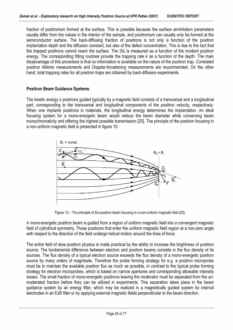
fraction of positronium formed at the surface. This is possible because the surface annihilation parameters usually differ from the values in the interior of the sample, and positronium can usually only be formed at the semiconductor surface. The back-diffusing fraction of positrons is not only a function of the positron implantation depth and the diffusion constant, but also of the defect concentration. This is due to the fact that the trapped positrons cannot reach the surface. The (fs) is measured as a function of the incident positron energy. The corresponding fitting routines provide the trapping rate k as a function of the depth. The main disadvantage of this procedure is that no information is available on the nature of the positron trap. Correlated positron lifetime measurements and Doppler-broadening measurements are recommended. On the other hand, total trapping rates for all positron traps are obtained by back-diffusion experiments. Positron Beam Guidance Systems The kinetic energy o positrons guided typically by a magnetic field consists of a transversal and a longitudinal part, corresponding to the transversal and longitudinal components of the positron velocity, respectively. When one implants positrons in materials, the longitudinal energy determines the implantation. An ideal focusing system for a mono-energetic beam would reduce the beam diameter while conserving beam monochromaticity and offering the highest possible transmission [20]. The principle of the positron focusing in a non-uniform magnetic field is presented in figure 10
Figure 10 – The principle of the positron beam focusing in a non-uniform magnetic field [20]. A mono-energetic positron beam is guided from a region of uniform magnetic field into a convergent magnetic field of cylindrical symmetry. Those positrons that enter the uniform magnetic field region at a non-zero angle with respect to the direction of the field undergo helical motion around the lines of force. The entire field of slow positron physics is made practical by the ability to increase the brightness of positron source. The fundamental difference between electron and positron beams consists in the flux density of its sources. The flux density of a typical electron source exceeds the flux density of a mono-energetic positron source by many orders of magnitude. Therefore the probe forming strategy for e.g. a positron microprobe must be to maintain the available positron flux as much as possible, in contrast to the typical probe forming strategy for electron microprobes, which is based on narrow apertures and corresponding allowable intensity losses. The small fraction of mono-energetic positrons leaving the moderator must be separated from the un-moderated fraction before they can be utilized in experiments. This separation takes place in the beam guidance system by an energy filter, which may be realized in a magnetically guided system by internal electrodes in an ExB filter or by applying external magnetic fields perpendicular to the beam direction.

Zeman et al. - Exploratory research on High Intensity Positron Source at HFR Petten (2007) SCIENTIFIC REPORT
Page 25 of 77
Another simple method is the use of bent solenoids and simply the un-moderated positrons are stopped in a shield. High-vacuum conditions (< 10-6 Pa) are sufficient for the guidance system and positron studies near the sample surface. Ultra-high vacuum is only required in connection with surface studies. In this case, the specimen chamber should be separated by a differential pumping station. The source–moderator arrangement is placed in front of a drift tube, at the end of which the positrons are entering the ExB filter. The mono-energetic positron beam is guided into the system axis and through a linear accelerator with a maximum energy up to 50 keV. The fast positrons are stopped in the collimator. The positron emission angle to the normal of the moderator foil amounts to a few degrees. A longitudinal magnetic field, which is spread over the whole beam system, forces the positrons onto a helical trace. This ensures that all emitted slow positrons reach the target. A system of guidance coils generates this longitudinal field. The beam guiding can also be done by a system of electrostatic lenses. The main advantage is the possibility of focusing the beam. The design of such a lens system is rather complicated due to the broad energy variation of the positron beam.

Zeman et al. - Exploratory research on High Intensity Positron Source at HFR Petten (2007) SCIENTIFIC REPORT
Page 26 of 77
Chapter (iv) HIPOS PRE-DESIGN
by A.ZEMAN
Zeman et al. - Exploratory research on High Intensity Positron Source at HFR Petten (2007) SCIENTIFIC REPORT
Page 27 of 77
4. HIPOS pre-design
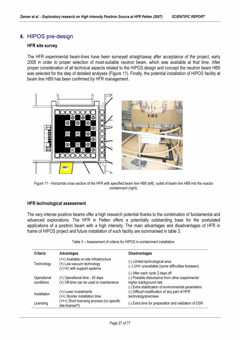
HFR site survey The HFR experimental beam-lines have been surveyed straightaway after acceptance of the project, early 2005 in order to proper selection of most-suitable neutron beam, which was available at that time. After proper consideration of all technical aspects related to the HIPOS design and concept the neutron beam HB9 was selected for the step of detailed analyses (Figure 11). Finally, the potential installation of HIPOS facility at beam line HB9 has been confirmed by HFR management.
Figure 11 - Horizontal cross section of the HFR with specified beam line HB9 (left), outlet of beam line HB9 into the reactor containment (right).
HFR technological assessment
The very intense positron beams offer a high research potential thanks to the combination of fundamental and advanced explorations. The HFR in Petten offers a potentially outstanding base for the postulated applications of a positron beam with a high intensity. The main advantages and disadvantages of HFR in frame of HIPOS project and future installation of such facility are summarised in table 3,
Table 3 – Assessment of criteria for HIPOS in-containment installation.
Criteria Advantages Disadvantages
Technology (++) Available on-site infrastructure (+) Low-vacuum technology (+) HV with support systems
(-) Limited technological area (--) UHV unavailable (some difficulties foreseen)
Operational conditions
(+) Operational time - 20 days (+) Off-time can be used to maintenance
(-) After each cycle 2 days off (-) Possible disturbance from other experiments/ higher background rate (-) Extra stabilization of environmental parameters
Installation (+) Lower investments (++) Shorter installation time
(-) Difficult modification of any part of HFR technology/premises
Licensing (+++) Short licensing process (no specific site-license!!!) (-) Extra time for preparation and validation of DSR

Zeman et al. - Exploratory research on High Intensity Positron Source at HFR Petten (2007) SCIENTIFIC REPORT
Page 28 of 77
REAC
TOR
CO
RE
Figure 12 – Vertical cross-section of HB9 beam line through the biological shielding of reactor including the positron generator (in
red) and beam shutter (in green). Technological area including support systems is foreseen on the 1st floor of the HFR containment, where the bended positron beam will be transported via magnetic-tilted transportation beam line, see figure 12-14. Figure 13 – Photo: end of HB9 beam line including the biological shielding (red elipse), vertical bending and horizontal bending of
the beam (green arrows), technological area (blue rhombus).
Technological area
Zeman et al. - Exploratory research on High Intensity Positron Source at HFR Petten (2007) SCIENTIFIC REPORT
Page 29 of 77
Position of HIPOS source
HFR reactor core
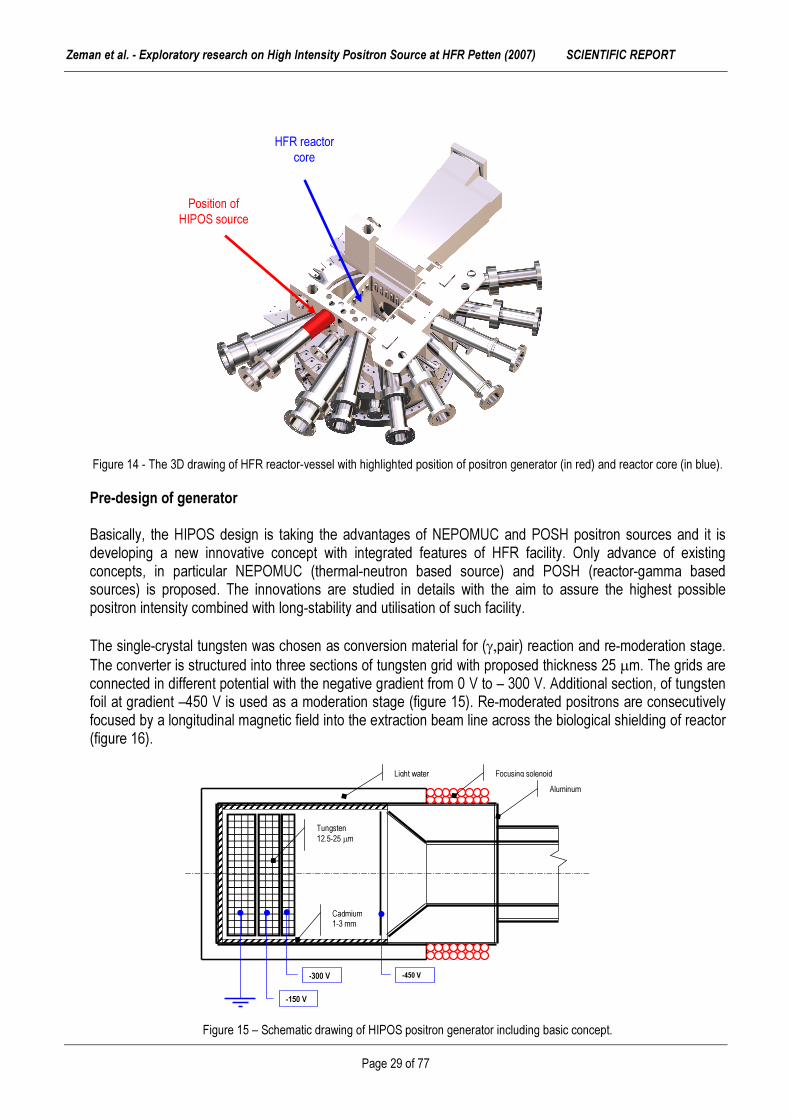
Figure 14 - The 3D drawing of HFR reactor-vessel with highlighted position of positron generator (in red) and reactor core (in blue).
Pre-design of generator Basically, the HIPOS design is taking the advantages of NEPOMUC and POSH positron sources and it is developing a new innovative concept with integrated features of HFR facility. Only advance of existing concepts, in particular NEPOMUC (thermal-neutron based source) and POSH (reactor-gamma based sources) is proposed. The innovations are studied in details with the aim to assure the highest possible positron intensity combined with long-stability and utilisation of such facility. The single-crystal tungsten was chosen as conversion material for (γ,pair) reaction and re-moderation stage. The converter is structured into three sections of tungsten grid with proposed thickness 25 µm. The grids are connected in different potential with the negative gradient from 0 V to – 300 V. Additional section, of tungsten foil at gradient –450 V is used as a moderation stage (figure 15). Re-moderated positrons are consecutively focused by a longitudinal magnetic field into the extraction beam line across the biological shielding of reactor (figure 16).
Figure 15 – Schematic drawing of HIPOS positron generator including basic concept.
-450 V
-150 V
-300 V
Tungsten 12.5-25 µm
Cadmium 1-3 mm
Light water Aluminum
Focusing solenoid

Zeman et al. - Exploratory research on High Intensity Positron Source at HFR Petten (2007) SCIENTIFIC REPORT
Page 30 of 77
Figure 16 - The 3D drawing of HFR reactor including the location of beam line HB9 and its crossing through biological shielding. The fast positrons are stopped directly in the narrowing part of the collimator. The positron emission angle to the normal of the moderator foil amounts to a few degrees. A longitudinal magnetic field, which is leveraged over the whole beam system, forces the positrons onto a helical trace. This ensures that all emitted slow positrons reach the proper direction. A system of guidance coils generates this longitudinal field. The beam guiding can also be done by a system of electrostatic lenses. The main advantage is the possibility of focusing the beam. The design of such a lens system is rather complicated due to the broad energy variation of the positron beam. A serious issue with the heat loading of positron generator is foreseen with total heat generation at level 2-3 kW. Therefore a cooling capsule is designed to reduce the operational temperature of whole structure of the HIPOS. The light water is proposed in pre-design phase. This type of the cooling is used also, as a re-moderator of fast neutrons, which are unwanted, since the neutrons with energy above 0.5 MeV have unfavourable effect due to generation of radiation degradation of microstructure of the tungsten in the converter and the re-moderation stage. The complete material and dimensional optimisation has been done and the results are reported in further chapters of this report.
BBeeaamm sshhuutttteerr BBeeaamm lliinnee HHBB99
RReeaaccttoorr vveesssseell BBiioollooggiiccaall sshhiieellddiinngg

Zeman et al. - Exploratory research on High Intensity Positron Source at HFR Petten (2007) SCIENTIFIC REPORT
Page 31 of 77
Chapter (v) HFR SOURCE DEFINITION
by A.HOGENBIRK

Zeman et al. - Exploratory research on High Intensity Positron Source at HFR Petten (2007) SCIENTIFIC REPORT
Page 32 of 77
5. HFR source definition
MCNP - model definition Within beam tube HB9 of the Petten High Flux Reactor a strong positron source is to be built by JRC-IE. The basis for the design calculations will be needed by an initial analysis of the HFR core, which is carried out by NRG. The results of this initial analysis of an HFR reference core are summarised in the report. The analysis was carried out with the Monte Carlo code MCNP by NRG due to exclusive rights for HFR core configuration and specification. The starting point, a MCNP-model of the HFR is shown by Figure 17. The normalisation of all results was done using the factor 3.41 x 10¹⁸ neutrons/s, as determined for this type of HFR model. This has been obtained throughout the HEU/LEU conversion studies. The use of the neutronics code MCNP in combination with these nuclear data was validated specifically for the present calculation.
Figure 17 - Horizontal cross section through the MCNP model of beam tube HB9, which used in the second step of the analyses.
Identifiers for surfaces (in black) and volumes (in red) are given. An impression of the neutron and photon fields at the entrance of HB9 is given in Figure 18. The outputs of MCNP calculations are based on: (a) Initial analysis, in which the wssa-file was produced. These results are identified by the string ”Initial
analysis”. (b) Secondary analysis, in which the wssa-file produced in the first step was used as a radiation source.
These results are identified by the string ”Analysis with WSSA”. (c) Secondary analysis, in which the radiation source was represented by energy and angular (d) Distributions for neutrons and photons as derived from the relevant tally-values obtained in the initial
analysis. These results are identified by the string ”Analysis with SDEF”. Note that there is a small difference between the initial analysis and the secondary analyses as far as the locations are concerned where the currents and fluxes were calculated. In the secondary analyses the cylindrical plane extends a bit more in the direction of the reactor, while the plane surface at the entrance of HB9 is a bit smaller in secondary analyses. This will lead to a somewhat larger value of the flux on the plane

Zeman et al. - Exploratory research on High Intensity Positron Source at HFR Petten (2007) SCIENTIFIC REPORT
Page 33 of 77
surface in the original analyses as compared with the secondary analyses. Likewise, in the secondary analyses the flux on the cylindrical surface will be a bit larger than in the initial analysis. ENDF/B-VI.5 evaluation [21] was applied for all other nuclides. This choice was made in [22] and has been used throughout the HEU/LEU conversion studies. The use of the neutronics code MCNP in combination with these nuclear data was validated specifically for the present calculation in [23]. The production of photons can be divided into two parts: the part from photons that are generated by radiative capture (e.g. 238U or 27Al capturing a neutron, thereby generating photons) and the part from fission product decay (e.g. 86Br that decays to 86Kr while emitting photons). The photon production due to radiative capture is usually described by the nuclear data library. A neutronics code like MCNP can, based on photon production cross sections on the library, simulate these prompt photons [24]. There are, however, some notable exceptions. The nuclear data for 113Cd, which is a strong absorber and therefore a strong photon source in the reactor, lack photon production data on JEF(F) and ENDF/B nuclear data libraries. Therefore the Cd nuclear data for the calculations described here were taken from JENDL-3.3. Also, the photon production data for 160 was recently found to be inaccurate in all nuclear data libraries [25]. Here the improved 160 data developed for neutron logging applications have been used. The same nuclear data as in other HFR conversion studies is used for all other isotopes: JEF-2.2 for 235U and 27Al, and ENDF/B-VI.5 for the rest. The simulation of fission product gammas, sometimes called delayed photons, is more problematic. There is, to our knowledge, no neutronics code that can both calculate the number of delayed photons produced per unit of time (a burnup code like Fispact can do this), and calculate the transport of the photons (a transport code like MCNP does this). We have opted for the use of an engineering correlation, as described in Ref. [26]. The energy distribution of the delayed photons is described reasonably well by the function,
01.1)( EECeEf γγ
−
= (with E0 = 1 MeV) (5.1) The normalization constant C is chosen such that the number of delayed photons per fission is, on average, 7.4 [26]. Since the average energy of the above distribution is 1/1.1 MeV, the amount of energy represented by these delayed photons is 6.72 MeV/fission. This is 3.7% of 180 MeV, which is a rough estimate of the fission energy. Subsequent analyses was carried out by directly by JRC-IE and was based on a specification of the radiation source (neutrons and photons) in terms of energy and angular distributions or on the information contained in the wssa-file. The first option allows the use of codes different than MCNP, the second option is only possible when MCNP(X) is used. In first instance, in the NRG MCNP analyses the wssa-file was generated on the front entrance of HB9 (a plane boundary) and on the skewed cylindrical side surface of HB9. However, it appeared that (due to a bug in the code) MCNP yields erroneous results when particle tracks are restarted from a skewed cylindrical surface. Therefore, a revised model was created. A horizontal cross section through this revised MCNP model is given in figure 18. The identifiers for surfaces and volumes are given in this figure. A cylindrical surface (with the axis parallel to the y-axis, identifier 9127) was added, which surrounds HB9 completely. In the revised analysis the wssa-file was created on the front entrance of HB9 and on this surrounding cylindrical surface.

Zeman et al. - Exploratory research on High Intensity Positron Source at HFR Petten (2007) SCIENTIFIC REPORT
Page 34 of 77
A B
(cm) (cm)
φ (cm-2s-1) φ (cm-2s-1) Figure 18 - Distribution of (A) neutrons and (P) photons entering the plane surface of beam tube HB9 (flux values are given in
units cm-2s-1 for a reactor power of 45 MW, dimensions along the axes are in cm).
Coupling between first and second step The first step of the analyses may be coupled to the subsequent step by two different methods: (a) The surface source file from the first step (the wssa-file) containing the information on the individual
particle tracks, which contribute to the response in beam tube HB9 may be used as a source (rssa-file) in a second MCNP analysis. This approach leads to no loss of information and provides the most accurate results.
(b) A specification of the radiation source deduced from the relevant tallies (i.e. energy and angular
distributions) in the first step may be used in the second step (using the SDEF-card in MCNP). This option involves approximations, as the radiation will be assumed to be homogeneously distributed on the surface on which the source is specified. Furthermore, the energy- and angular distributions of the neutrons and the photons will be assumed to be independent.
Note that MCNP does not accept sampling from cylindrical surfaces. This implies that in this case only the neutrons and photons impinging on the front surface of beam tube HB9 may be taken into account. However, this drawback of MCNP was mended in MCNPX [27]. Using MCNPX in the second step therefore allows the use of the complete (SDEF) specification of the radiation source. If computer codes other than MCNP are to be used the information from the first step needs to be translated into a different format. To this end a FORTRAN program is supplied by NRG, which reads particle tracks from the (binary) surface source file (wssa) and translates them to ASCII. By modifying the code it is possible to carry out arbitrary translations. Likewise, the SDEF specification may be translated into a source specification for a different code. NOTE: In the secondary analyses care should be taken to sum the contributions from the plane surface of beam tube HB9 and from the cylindrical surface of beam tube HB9 with the correct normalization factors. In this case these factors are:

Zeman et al. - Exploratory research on High Intensity Positron Source at HFR Petten (2007) SCIENTIFIC REPORT
Page 35 of 77
Table 4 – The normalization factors for pane and cylindrical surface of beam tube HB9, factors are consistent with a neutron source strength of 3:41E +18 s-1 (equivalent with a reactor power of 45 MW).
MCNP results – reactor source file definition An impression of the neutron and photon fields at the entrance of HB9 is given in figure 19. The neutron and photon currents at surfaces surrounding beam tube HB9 are specified in table 4. In these figs. the results are given for three different analyses: 1. Initial analysis, in which the wssa-file was produced. These results are identified by the string “Initial
analysis”. 2. Secondary analysis, in which the wssa-file produced in the first step was used as a radiation source.
These results are identified by the string “Analysis with WSSA”. 3. Secondary analysis, in which the radiation source was represented by energy and angular distributions
for neutrons and photons as derived from the relevant tally-values obtained in the initial analysis. These results are identified by the string “Analysis with SDEF”.
Numerical values of the neutron and photon fluxes bounding beam tube HB9 are given in table 5.
Table 5 – Energy-integrated neutron fluxes for a reactor power of 45 MW at the planes bounding beam line HB9 for the three calculations.
NOTE: there is a small difference between the initial analysis and the secondary analyses as far as the locations are concerned where the currents and fluxes were calculated. In the secondary analyses the cylindrical plane extends a bit more in the direction of the reactor, while the plane surface at the entrance of HB9 is a bit smaller in secondary analyses. This will lead to a somewhat larger value of the flux on the plane surface in the original analyses as compared with the secondary analyses. Likewise, in the secondary analyses the flux on the cylindrical surface will be a bit larger than in the initial analysis.
Sufrace Neutrons Photons Plane 1:756506E+166 4:666900E+16 Cylindrical 1:802892E+16 4:119829E+16
Surface Analysis Neutron flux (cm-2s-1) Photon flux (cm-2s-1)
Plane Initial WSSA SDEF
9.58E+14 ± 3.35E+11 8.33E+13 ± 3.00E+11 8.32E+13 ± 6.66E+10
2.03E+14 ± 8.93E+11 1.81E+14 ± 7.96E+11 1.92E+14 ± 1.53E+11
Cylindrical Initial WSSA SDEF
5.29E+13 ± 1.80E+11 5.41E+12 ± 1.84E+11 5.80E+13 ± 4.06E+10
1.25EC14 ± 4.86E+11 1.27EC14 ± 4.84E+11 1.27EC14 ± 1.02E+11

Zeman et al. - Exploratory research on High Intensity Positron Source at HFR Petten (2007) SCIENTIFIC REPORT
Page 36 of 77
Figure 19. – (A) Neutron and (B) photon flux of HB9 plane surface; (C) neutron and (D) photon flux of HB9 cylindrical surface (for a
reactor power of 45 MW). Discussion The results presented in section 4 provide a verification of the calculational approaches, which can be followed to design the HIPOS facility in beam tube HB9 of the HFR. The two possible calculational routes consist of using the wssa-file in a secondary MCNP analysis or the use of an analytical source description, which can be used by an arbitrary radiation transport code. In these secondary analyses surface-integrated currents and fluxes were calculated. The most accurate results are obtained by the method in which the wssa-file is used. No serious discrepancies are observed in this case; the occurring differences may be attributed to small discrepancies in the definition of tally surfaces in the secondary analyses as compared to the initial analysis. When the sdef-description is used in the secondary analysis somewhat larger discrepancies are observed. The most prominent discrepancies are observed for the neutron flux. The maximum discrepancy is 8% for the energy-integrated neutron flux at the cylindrical surface of HB9 (see table 5). Using the analytical source distribution two energy and angular distributions are used for source neutrons: one for neutrons starting at the plane surface and one for neutrons starting at the cylindrical surface. In reality the energy and angular distribution of the latter kind of neutrons will be strongly position-dependent. Neutrons close to the reactor vessel will be anisotropic; neutrons far from the reactor will be approximately isotropic. This implies that if the sdef-description is used close to the reactor the angular distribution will be more isotropic than in reality and farther from the reactor the angular distribution will be more anisotropic than in reality. Hence, we expect a decrease of the fast neutron flux and an increase of the thermal neutron flux at the cylindrical surface of beam tube HB9.
A B
C D
Zeman et al. - Exploratory research on High Intensity Positron Source at HFR Petten (2007) SCIENTIFIC REPORT
Page 37 of 77
Chapter (vi) EXPERIMENTAL VALIDATION OF HB9 SOURCE
by A.HOGENBIRK

Zeman et al. - Exploratory research on High Intensity Positron Source at HFR Petten (2007) SCIENTIFIC REPORT
Page 38 of 77
6. Experimental validation of MCNP outcomes
The experimental validation of MCNP calculation procedures of HFR source was needed due to relatively high level of uncertainties of gamma radiation HB9 beam line. This experiments were carried out in order to validate chosen calculational model for HIPOS purpose. Such validated outcomes has been consecutively applied in further calculations by MCNPX and GEAN4 codes. This positron beam will be produced in a two-step process. In the first step thermal neutrons are converted into gamma radiation in a cadmium converter. In their turn, these gammas will be converted into positrons in a subsequent tungsten converter. In the design phase of this facility JRC has made extensive use of Monte Carlo radiation transport simulations applying the MCNP code. It is of great importance that a good agreement exists between the results of these Monte Carlo simulations and the actual experimental conditions. For this purpose a validation of the calculational approach is needed. This phase of simulations have been carried out by NRG due to exclusive rights to the reactor data. According to the original plan of the experimental validation, the measurements were foreseen in the vertical channel between beryllium assembly C9 and the vessel wall. However, these measurements failed due to unexpected reason. Therefore NRG has performed alternative measurements on several locations close to the entrance of HB9 neutron beam. Original measurement plan In [28] it was specified that in order to validate the calculation approach measurements would be carried out by NRG in the vertical channel between beryllium assembly C9 and the reactor vessel wall. In these measurements several foils were to be irradiated. The activity of the samples would also be calculated in MCNP simulations. This would yield information regarding the agreement to be expected between the results of measurements and MCNP simulations. The experiment was carried out using a monitor holder containing a nickel and a copper wire and a foil set to determine the reaction rates and neutron spectrum [29]. Because of the partial blockage of a cooling channel of beryllium assembly C9 thermal hydraulics analyses had to be carried out, which are reported in [30,31]. The rather frail monitor holder was placed in the reactor in HFR cycle 0603. At the end of this cycle, however, it appeared that the monitor holder had failed. It appeared to be not recoverable, which implied that a revised measurement plan had to be made. This plan was discussed in a meeting held on 19 May 2006 in F. Wijtsma’s office, with A. Zeman, L. Debarberis, F. Wijtsma, A. Paardekooper and A. Hogenbirk present. It was decided to use the following approach: 1. Carry out an activation measurement in the PRS facility, which is located outside the reactor wall close to
HB9. 2. Use the activation measurements carried out in the TIRO facility at location D8 in HFR cycle 0603. 3. Use the copper wire measurements in HFR cycle 0603, which provide information about the thermal
neutron flux at location C8. This approach provides a maximum of experimental information in a relatively short time.
PRS measurements

Zeman et al. - Exploratory research on High Intensity Positron Source at HFR Petten (2007) SCIENTIFIC REPORT
Page 39 of 77
PRS
HB9
The Pneumatic Rabbit System (PRS) is a facility in the HFR, which consists of a tube in which a sample can be irradiated. Movement of the sample is by air-pressure, implying that the sample can easily be manipulated without disturbing the reactor. The sample consists of a polyethylene cylinder, comprised of two parts, which can be screwed together. Inside the sample the material (in this case activation foils) can be placed which will be irradiated. The irradiation position of the sample is fixed. It is outside the core box, south of the reactor, east of HB9. An impression of the horizontal location of the PRS sample is given in figure 19. The PRS facility is shielded from the gammas produced by the HFR by a lead shield on the north side of the facility.
Figure 19 – Horizontal cross section of the MCNP model of the HFR, showing the location of the PRS facility and HB9 beam line [28].
TIRO measurements During the conversion of the HFR from high enriched (HEU) fuel to low enriched fuel (LEU) new calculational methods have been introduced. These include the new operational tool for cycle calculations OSCAR-3 [32] and the high-precision neutronics tools REBUS and MCNP [28]. These new tools have to be validated for the application of HFR cycle calculations. This is the reason why on several locations in the HFR activation measurements have been performed during the conversion process. One of these locations is position D8 of the HFR, where a TIRO-2 experimental facility is placed. This D8 location is relevant for the HIPOS project, as it yields information close to the entrance of beam tube HB9. The following reactions were used: � 59Co(n;γ) � 58Ni (n;p) � 54Fe (n,p) � 58Fe (n;γ) � 109Ag (n;γ)
This implies that both the thermal, intermediate and fast part of the neutron spectrum are probed. Copper wire measurements Preceding cycle 0603 a special measuring core was built in the HFR (identification 10.520). The purpose of this activity was to provide data for the validation of the calculational approach for HFR simulations. The measuring core consists of a core in which all experimental facilities are replaced by Al plugs. The PSF was

Zeman et al. - Exploratory research on High Intensity Positron Source at HFR Petten (2007) SCIENTIFIC REPORT
Page 40 of 77
left empty. Copper wires were inserted on several locations in the HFR. The wires were activated at a low reactor power of approximately 500 kW. Important for the HIPOS project is location C8, were a flux wire was activated in the central location of the element. Note that in the measuring core no absolute measurements were performed; only relative data were obtained. However, the global normalisation factor is a result of many flux wire measurements. A failure to reproduce the data at a specific location (e.g. location C8) would therefore immediately show up in the resulting C /E data at this location. Calculational procedure The neutronics simulations carried out in the framework of this project were performed with a validated version of the Monte Carlo code MCNP4C3 [33,34]. Validated nuclear data were taken from the ENDF/B-VI.5 and JEF-2.2 evaluations [35,36]. In order to calculate the activity of the irradiated foils special dosimetry data were taken from the DOSCROSS-2001 library [37]. A realistic MCNP model for the HFR was used in the analyses, containing the actual core loading (both experiments and fuel) of the reactor during the measurements. Furthermore, the burn-up of the fuel and control rods was taken into account by using the material specifications consistent with the Mid Of Cycle (MOC). Calculational results
PRS simulations In the simulations of the PRS experiment the activation of the foils was calculated. A summary of the analyses is given in table 6, in which the C/E-values are given. Note that two values are given, corresponding to a calculation of the activities as calculated in the centre of the PRS sample (indicated by C/E (centre), the activities as calculated integrated over the complete PRS sample volume (indicated by C/E (total)). The latter value was calculated for the sake of statistics: the volume to the centre of the PRS sample is rather small, which results in a relatively large statistical uncertainty for a given calculation time.
Table 6 - Results of the comparison between experimentally determined and calculated activities of the PRS foils for several reactions (see text). C/E-values are given with combined absolute statistical uncertainties.
Reaction C/E(centre) C/E(total) 59Co (n,γ) 0.987±0.05 1.051±0.02 58Fe (n,γ) 1.072±0.05 1.135±0.03 109Ag (n,γ) 0.984±0.09 1.047±0.04 54Fe (n,p) 1.037±0.43 0.876±0.09 58Ni. (n,p) 0.959±0.40 0.836±0.08
For the reactions sensitive to thermal neutrons a good agreement is observed between measured and calculated activities. On the PRS location the fast neutron flux has already substantially decreased. This results in rather large uncertainties for the C/E-value in the PRS centre. The C/E-value for the total PRS sample volume shows that also for the reactions sensitive to fast neutrons an acceptable agreement is obtained between measured and calculated activities.
TIRO measurements The results of the measurements as carried out in the TIRO facility located in D8 are given in table 7.

Zeman et al. - Exploratory research on High Intensity Positron Source at HFR Petten (2007) SCIENTIFIC REPORT
Page 41 of 77
Table 7 - Results of the comparison between experimentally determined and calculated activities of the foils in the TIRO facility at HFR position D8. Results are given in the form of C /E-1-values for a number of recent HFR cycles.
Cycle 59Co (n,γ) 58Fe (n,γ) 54Fe (n,p) 58Ni. (n,p) 109Ag (n,γ) 0511 -0.046 -0.054 0.000 -0.039 -0.001 0512 -0.044 -0.036 -0.049 -0.076 -0.010 0601 -0.042 -0.038 0.008 -0.034 0.030 0602 -0.034 -0.031 -0.010 -0.049 0.014 0603 -0.019 -0.031 0.035 0.001 0.104
Copper wire measurements The C/E –1- results of the copper wire activation measurements in HFR measuring core 10.520 are shown in figure 20. Figure 20 – (A) Thermal flux determined by experimental measurement (exp) and calculation (calc) of copper wire activity in HFR position C8; (B) graphical interpretation of thermal flux (C/E-1) value as a function of axial position along the flux wire in HFR position C8 for measuring core 10.520. Discussion From the comparison of measured and calculated fluxes and reaction rates it is clear that the calculational approach which is outlined above yields a good description of the neutron field in the neighbourhood of the entrance of HFR beam line HB9. Both the PRS measurements, the measurements carried out in the TIRO facility and the copper wire activation measurements indicate that the neutron flux may be calculated with an accuracy of around 5%. Therefore, the first step of the calculational approach as defined in [28] is validated. No -flux measurements were carried out. The calculation of the direct -source was therefore not validated. However, most of the ’s to be used as a positron source in the HIPOS facility will be generated by thermal neutrons in the cadmium converter. Hence, the results given above provide a good validation of the calculation of the primary - source in the HIPOS facility.
Axial position (cm) Axial position (cm)
Relat
ive flu
x
(C-E
)/E
A B

Zeman et al. - Exploratory research on High Intensity Positron Source at HFR Petten (2007) SCIENTIFIC REPORT
Page 42 of 77
Chapter (vi) HIPOS COMPUTER CALCULATIONS
by K.TUČEK and G.DAQUINO

Zeman et al. - Exploratory research on High Intensity Positron Source at HFR Petten (2007) SCIENTIFIC REPORT
Page 43 of 77
7. HIPOS computer calculations Methods This section presents results of the modelling and optimization of the design of the HIPOS converter. The thicknesses of the cadmium neutron-gamma-positron converter and tungsten converter/moderator were optimized to increase yield of slow positrons while respecting material and system characteristics as cadmium burn-up and thermal load. The characteristics of the HIPOS design based on platinum converter/moderator were compared to the reference design, which uses tungsten. Finally, we compared calculation results obtained by two Monte Carlo codes, MCNPX and GEANT4, for a simplified geometric set-up of the HIPOS. The HFR neutron and photon source definition has been transformed into specific formats of MCNPX and GENAT4 codes.
Figure 21 - The MCNPX input of (A) neutron source energy spectrum and (B) photon source energy spectrum at HB9 position
(plane and cylindrical position).
1E-10 1E-8 1E-6 1E-4 0.01 11E10
1E12
1E14
1E16
1E18
n-flu
x (s-1
)
Energy (MeV)
n-plane n-cylind n-sum
Scoring surface of HB9
0.01 0.1 1 101E10
1E12
1E14
1E16
1E18
γ-flux
(s-1)
Energy (MeV)
n-plane n-cylind n-sum
Scoring surface of HB9
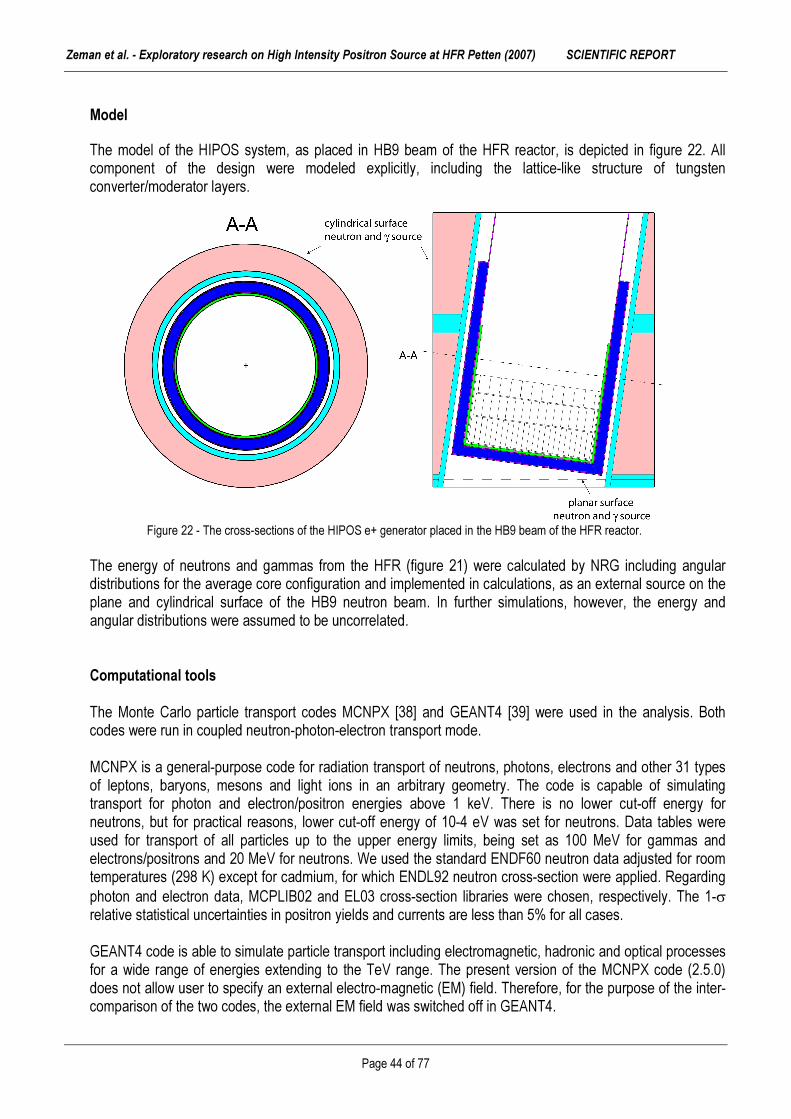
Zeman et al. - Exploratory research on High Intensity Positron Source at HFR Petten (2007) SCIENTIFIC REPORT
Page 44 of 77
Model
The model of the HIPOS system, as placed in HB9 beam of the HFR reactor, is depicted in figure 22. All component of the design were modeled explicitly, including the lattice-like structure of tungsten converter/moderator layers.
Figure 22 - The cross-sections of the HIPOS e+ generator placed in the HB9 beam of the HFR reactor. The energy of neutrons and gammas from the HFR (figure 21) were calculated by NRG including angular distributions for the average core configuration and implemented in calculations, as an external source on the plane and cylindrical surface of the HB9 neutron beam. In further simulations, however, the energy and angular distributions were assumed to be uncorrelated. Computational tools The Monte Carlo particle transport codes MCNPX [38] and GEANT4 [39] were used in the analysis. Both codes were run in coupled neutron-photon-electron transport mode. MCNPX is a general-purpose code for radiation transport of neutrons, photons, electrons and other 31 types of leptons, baryons, mesons and light ions in an arbitrary geometry. The code is capable of simulating transport for photon and electron/positron energies above 1 keV. There is no lower cut-off energy for neutrons, but for practical reasons, lower cut-off energy of 10-4 eV was set for neutrons. Data tables were used for transport of all particles up to the upper energy limits, being set as 100 MeV for gammas and electrons/positrons and 20 MeV for neutrons. We used the standard ENDF60 neutron data adjusted for room temperatures (298 K) except for cadmium, for which ENDL92 neutron cross-section were applied. Regarding photon and electron data, MCPLIB02 and EL03 cross-section libraries were chosen, respectively. The 1-σ relative statistical uncertainties in positron yields and currents are less than 5% for all cases. GEANT4 code is able to simulate particle transport including electromagnetic, hadronic and optical processes for a wide range of energies extending to the TeV range. The present version of the MCNPX code (2.5.0) does not allow user to specify an external electro-magnetic (EM) field. Therefore, for the purpose of the inter-comparison of the two codes, the external EM field was switched off in GEANT4.

Zeman et al. - Exploratory research on High Intensity Positron Source at HFR Petten (2007) SCIENTIFIC REPORT
Page 45 of 77
Gammas emitted in 113Cd (n,γ) reaction In order to determine reliability of gamma production data from neutron capture reaction in cadmium, we compared the evaluated gamma data from Evaluated Nuclear Structure Data File (ENSDF) library [40] with three cross-section libraries available at JRC/IE: the Lawrence Livermore National Laboratory evaluated ENDL92 shipped together with the standard MCNPX package and two Japanese Evaluated Nuclear Data Libraries, version 3.2 and 3.3 (JENDL 3.2 and JENDL 3.3). Because ENSDF library contains experimental data for 113Cd isotope and thermal neutron energies only, we first, however, investigated the probability of neutron capture in individual isotopes of cadmium plate placed in the HB9 beam and probability of neutron capture as a function of incident neutron energy. It appeared that in HB9 type of neutron spectra, more than 98.5% of all captures are on 113Cd isotope due to its large (60000 barns) 0.17 eV resonance (table 8 and figure 23). Additionally, calculations showed that more than 95% of neutron captures on cadmium are due to neutrons with energy below 0.5 eV (figure 23). Regarding the gamma production in (n,γ) reaction on Cd, we can therefore further assume that gammas emitted are due to thermal neutron capture on 113Cd. Table 8 - Neutron capture rate in individual cadmium isotopes. JENDL 3.3 cross-section library was used for this analysis.
Isotope Isotopic fraction (%) Fraction n-capture on Cd (%) 106Cd 1.25 0.02 108Cd 0.89 0.03 110Cd 12.49 0.28 111Cd 12.80 0.65 112Cd 24.13 0.25 113Cd 12.22 98.54 114Cd 28.73 0.21 116Cd 7.49 0.02
In the HB9-type of neutron spectra, about 45% of the neutrons entering the Cd converter (with a thickness 2.5 mm) are absorbed in the converter. This indicates that HB9 beam tube neutron spectrum is already fairly thermalised, when reaching the Cd converter (the average neutron source energy in the HB9 beam tube is 195 keV).
Figure 23 - Energy distribution of neutron captures in 113Cd in the HB9 neutron spectrum. To assess difference between the γ emission spectra from neutron capture in Cd, the MCNPX code was further modified to record energy of exiting gamma quanta from the neutron capture reaction on Cd using ENDL92, JENDL 3.2 and JENDL 3.3 data. The results are depicted together with evaluated gamma data from Evaluated Nuclear Structure Data File (ENSDF) library [40] in figure 24.

Zeman et al. - Exploratory research on High Intensity Positron Source at HFR Petten (2007) SCIENTIFIC REPORT
Page 46 of 77
Figure 24 - Comparison of gamma
quanta emission
from neutron
capture in cadmium.
ENSDF data correspond to thermal neutron
capture in 113Cd [32].
We observe that the data in ENDL92 and JENDL libraries are of different qualitative nature than those of ENSDF. While data in the former are given in the form of continuous probability density functions, the latter includes individual gamma energies as observed in the de-excitation of 114Cd. Additionally, the gamma spectra also differ in a quantitative way – with regard to the gamma multiplicity per neutron capture and energy spectrum of gamma quanta (see also table 9).
Table 9 - Gamma quanta multiplicity and spectrum energy for different data libraries investigated compared to HB9 beam total gamma source.
†Multiplicity for HB9 beam tube gammas is obtained by comparing gamma current behind the Cd converter (thickness 2.5 mm) to the number of neutron captures in Cd.
The estimation for multiplicity of gamma radiation [2,41] has not done correctly since lack of the date, therefore published factor 2.3 should be reduced at least by 20% for gamma multiplicity for neutron capture reaction on cadmium. Both gamma multiplicities and mean energies are higher for the standard MCNPX ENDL92 and JENDL cross-section libraries compared to ENSDF data. The same holds for fraction of gamma spectrum above pair production threshold (1.022 MeV), which means that number of high-energetic gammas creating electron-positron pair will be larger when these data are used in simulations than when ENSDF data are applied. In this context, we also note that mean energy of gamma quanta from the HFR reactor (HB9 beam spectrum) and the corresponding fraction of spectra above pair production threshold are lower than those for ENSDF library (table 9, figure 25). This indicates that importance of gamma quanta from neutron capture reactions in Cd in creating electron-positron pairs will be higher than for gammas from fission product de-excitation and neutron captures in the HFR core/reflector.
Parameter/Library ENDL 92 JENDL 3.2 JENDL 3.3 ENSDF HB9 Multiplicity [γ/capture] 3.62 3.83 4.40 1.96 1.55† Mean energy [MeV] 2.50 1.88 2.06 1.49 0.828 Fraction of γ spectra above pair production threshold (E > 1.022 MeV) [%]
71.4 59.0 67.7 39.7 24.1

Zeman et al. - Exploratory research on High Intensity Positron Source at HFR Petten (2007) SCIENTIFIC REPORT
Page 47 of 77
Because of this relative unsatisfactory quality of gamma production data in available MCNPX libraries (ENDL92, JENDL), the MCNPX code was for further studies modified to sample energy of exiting gammas from (n,γ) reaction in Cd according to ENSDF data. The gamma quanta were assumed to be emitted isotropically. Figure 25 - Relative comparison of gamma spectra in the HB9 beam tube to gamma quanta originating in thermal neutron capture
in 113Cd [32].

Zeman et al. - Exploratory research on High Intensity Positron Source at HFR Petten (2007) SCIENTIFIC REPORT
Page 48 of 77
Chapter (viii) HIPOS DESIGN OPTIMISATION
by K.TUČEK and A.ZEMAN
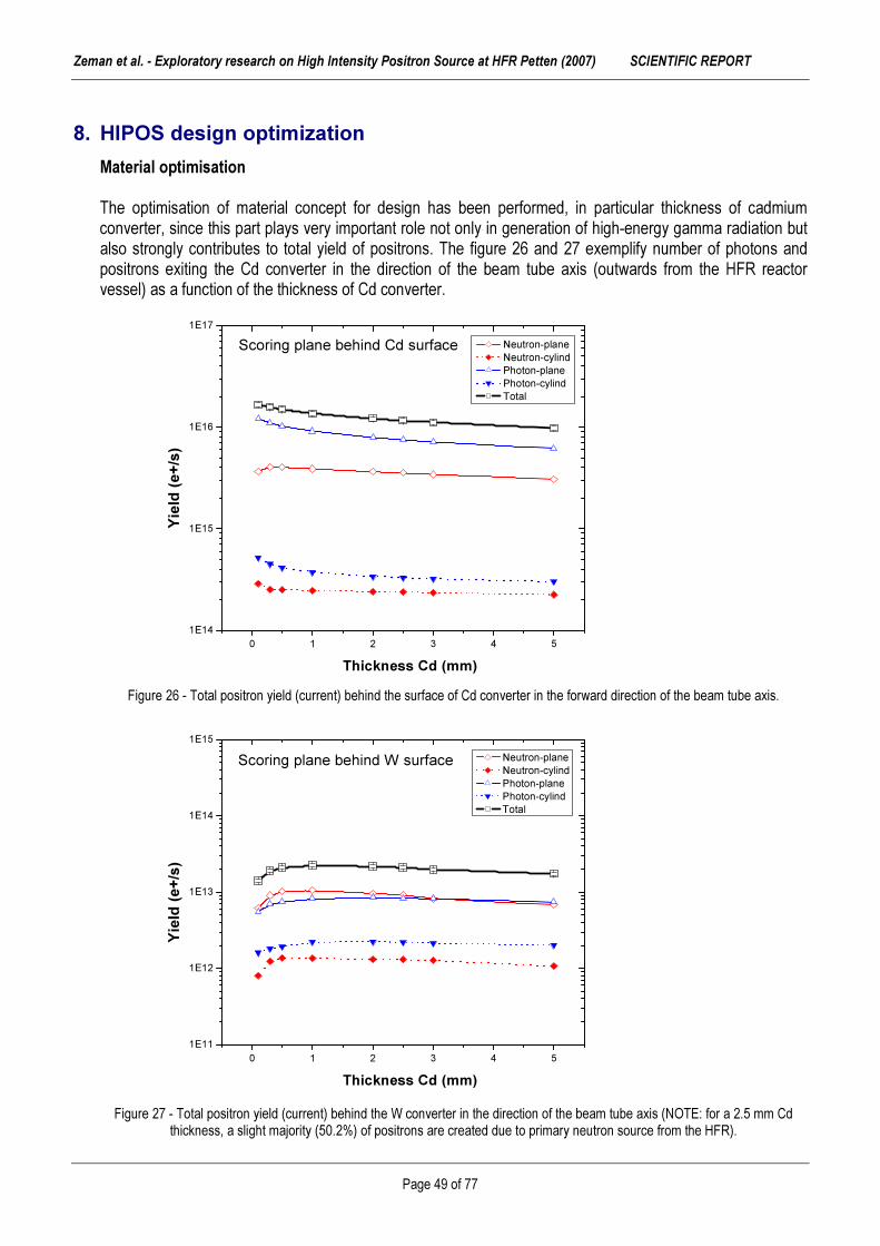
Zeman et al. - Exploratory research on High Intensity Positron Source at HFR Petten (2007) SCIENTIFIC REPORT
Page 49 of 77
8. HIPOS design optimization
Material optimisation The optimisation of material concept for design has been performed, in particular thickness of cadmium converter, since this part plays very important role not only in generation of high-energy gamma radiation but also strongly contributes to total yield of positrons. The figure 26 and 27 exemplify number of photons and positrons exiting the Cd converter in the direction of the beam tube axis (outwards from the HFR reactor vessel) as a function of the thickness of Cd converter.
Figure 26 - Total positron yield (current) behind the surface of Cd converter in the forward direction of the beam tube axis.
Figure 27 - Total positron yield (current) behind the W converter in the direction of the beam tube axis (NOTE: for a 2.5 mm Cd thickness, a slight majority (50.2%) of positrons are created due to primary neutron source from the HFR).
0 1 2 3 4 51E14
1E15
1E16
1E17
Yield
(e+/s
)
Thickness Cd (mm)
Neutron-plane Neutron-cylind Photon-plane Photon-cylind Total
Scoring plane behind Cd surface
0 1 2 3 4 51E11
1E12
1E13
1E14
1E15Scoring plane behind W surface
Yield
(e+/s
)
Thickness Cd (mm)
Neutron-plane Neutron-cylind Photon-plane Photon-cylind Total

Zeman et al. - Exploratory research on High Intensity Positron Source at HFR Petten (2007) SCIENTIFIC REPORT
Page 50 of 77
Electron-positron pairs are being produced both in cadmium and tungsten converter/moderator for photon energies above 1.022 MeV. The number positrons created in the cadmium-tungsten converter is an increasing function of the total number of neutrons and gammas absorbed in cadmium and gammas absorbed in tungsten. On one hand, enlarging the Cd thickness increases neutron capture rate and gamma absorption probability in the converter (figure 21), which results in higher pair production rate. On the other hand, however, higher Cd thickness has a detrimental effect on the probability of created positrons to leave the converter. In the current design, the total positron current behind tungsten converter in the outward direction of the beam axis attains a maximum for about 1 mm thick Cd converter (figure 26, table 10). However, the choice of optimum thickness of Cd converter is also a function of maximum attainable burn-up of 113Cd isotope while still keeping positron yield acceptable. The 113Cd burn-up becomes large (over 30 % per year) for Cd thicknesses below or at 1 mm, which would require frequent dismantling and replacement of the Cd converter. Instead, it appears to be more convenient to fix Cd thickness in the range of 2-3 mm, allowing the HIPOS to operate in 2-3 years intervals without a need to replace the converter. For the current design and our subsequent analyses, Cd converter thickness of 2.5 mm is chosen.
Table 10 - Positron yields together with annual burn-up of 113Cd in the converter of the HIPOS system having different Cd thicknesses. A load factor of 80% is assumed for the calculation of 113Cd burn-up.
Parameter/Cd thickness (mm) 0.1 0.3 0.5 1 2 2.5 3 5 Positron yield behind W converter in the forward direction [1013 e+/s] 1.41 1.90 2.10 2.24 2.16 2.10 1.97 1.73 Cd mass (g) 8.29 24.9 41.6 83.3 167.6 210.1 252.8 425.9 113Cd burn-up (%/year) 296 104 63.0 31.9 16.2 13.0 10.9 6.67
NOTE: the occurrence of 113Cd in natural Cd is only 12.22 at%. Hence, enriching Cd in 113Cd offers an interesting opportunity to further prolong the interval between Cd converter replacements. The energy spectrums of positrons together with their angular distribution relative to the beam tube axis are given in figures 27-30. The energy distribution of positrons behind the W converter peaks at about 1.1 MeV, with mean energy being 1.63 MeV. The fraction of positrons below 600 keV is 25.4%. Due to the self-absorption of positrons moving backwards (towards the reactor wall), the resulting spectrum of positrons becomes more forward oriented along the beam tube.
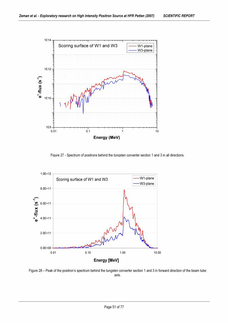
Zeman et al. - Exploratory research on High Intensity Positron Source at HFR Petten (2007) SCIENTIFIC REPORT
Page 51 of 77
Figure 27 - Spectrum of positrons behind the tungsten converter section 1 and 3 in all directions.
Figure 28 – Peak of the positron’s spectrum behind the tungsten converter section 1 and 3 in forward direction of the beam tube axis.
0.01 0.1 1 101E8
1E10
1E12
1E14
e+ -flux (
s-1)
Energy (MeV)
W1-plane W3-plane
Scoring surface of W1 and W3
Scoring surface of W1 and W3
0.0E+00
2.0E+11
4.0E+11
6.0E+11
8.0E+11
1.0E+12
0.01 0.10 1.00 10.00
Energy [MeV]
e+ -flux (
s-1)
W1-planeW3-plane

Zeman et al. - Exploratory research on High Intensity Positron Source at HFR Petten (2007) SCIENTIFIC REPORT
Page 52 of 77
Figure 29 – Angular distribution of produced positrons from each particular source of origin (n-planar, n-cylindrical, γ-planar and γ-cylindrical), the angle of 0°represents forward direction of the beam tube axis.
Figure 30 - Angular distribution (angle cosine) of positrons behind the tungsten plane of first section (W1) and last section (W3) relative to the beam tube axis.
10 10 10 11 10 12
10 10
10 11
10 12
neutron plane neutron cylind photon plane photon cylind
Angu
lar di
stribu
tion
FORWARD
BACKWARD
0°
-90° +90°
(e+)
0.E+00
1.E+12
2.E+12
3.E+12
4.E+12
5.E+12
-0.9 -0.6 -0.3 0 0.3 0.6 0.9cosine
Integ
ral c
urre
nt (e
+/s) W1-plane W3-plane

Zeman et al. - Exploratory research on High Intensity Positron Source at HFR Petten (2007) SCIENTIFIC REPORT
Page 53 of 77
The emission probability of thermalized positrons from tungsten plate is inversely proportional to the converter thickness. Therefore, a design variant with a 50% lower tungsten converter thickness (12.5 µm) was also investigated (table 11) to possibly further optimize yield of slow positrons. It was found that this design modification results in very similar integral positron yields (2.07·1013 e+/s vs. 2.11·1013 e+/s) as for the reference design.
Table 11 - Results of HIPOS system design optimization studies. Parameter/Design Reference
design Thickness of W
converter plate 12.5 µm D2O
moderator Platinum
converter and moderators
*Positron yield behind W converter [1013 e+/s] 2.10 2.07 1.92 2.18 *Positron yield behind W moderators [1013 e+/s] 1.21 1.18 1.18 1.24 Cd captures [1015/s] 5.87 5.87 5.22 5.88 113Cd burn-up [%/per year] 13.0 13.0 11.6 13.1
* Calculated only in the forward direction On the other hand, further thermalisation of neutron spectra by placing additional D2O moderator in front of the HIPOS in the beam tube (would require picture or omit), does not seem to increase neutron capture rates and consequently also gamma and positron yields. A use of platinum instead of tungsten in both the converter and moderators results in slightly higher integral positron yields. Platinum also holds a promise of having higher probability of emission of thermalised positrons, but its use is associated with economic penalties. An important factor in designing the HIPOS system is assuring appropriate cooling. In the HIPOS, thermal load is mainly due to the gamma and electron/positrons (table 12); the fraction of energy deposited in the system due to neutron (scattering) is less than 1%. For our reference design, 2.90 kW is generated in Cd converter, while the highest power density (4.66 W/g) is in the first tungsten converter/moderator unit. In Cd, a slight majority (51%) of heat generated is due to photons, while in W and Pt it is 58% and 55%, respectively. Table 12 - Thermal load due to gammas and electron/positrons in different components of the HIPOS. Data are given for reference design, design with modified tungsten converter thickness and system using platinum in converter/moderator instead of tungsten.
Parameter/Design Component Ref. design W-converter 12.5µm Pt-conver.& moder. Cd 0.87 0.89 0.87 W/Pt converter 1.95 1.71 1.79 γ−heating [W/g] 1st W/Pt moderator 2.43 2.43 2.53 Cd 0.83 0.83 0.83 W/Pt converter 1.42 1.40 1.47 e+/e- heating [W/g] 1st W/Pt moderator 2.23 2.23 2.32 Cd 2.90 2.90 2.89 W/Pt converter 0.025 0.012 0.027 Total heat [kW] 1st W/Pt moderator 0.21 0.21 0.24

Zeman et al. - Exploratory research on High Intensity Positron Source at HFR Petten (2007) SCIENTIFIC REPORT
Page 54 of 77
1.0E+08
2.0E+14
4.0E+14
6.0E+14
8.0E+14
1.0E+15
1.2E+15
1.0E-03 3.2E-03 1.0E-02 3.2E-02 1.0E-01 3.2E-01 1.0E+00
Energy (MeV)
Inten
sity
MCNPX-DLCGEANT4GEANT4-JENDL33MCNPX-JENDL33
Benchmarking - MCNPX vs GEANT4 For the purpose of inter-comparison of the analytical codes used in this study, the HIPOS geometry and external source specifications were somewhat simplified. The water channel was removed at the same time as the neutron source was assumed to be a beam of neutrons impinging perpendicularly to the centre of the beam plane.
Figure 31 - Comparison of gamma spectra on Cd surface calculated by MCNPX and GEANT4 using JENDL 3.3 library for a thermal mono-energetic planar neutron source (E = 0.025 eV). In the full HIPOS system geometry including beam tube channel, positron current behind the W converter in the forward direction is 1.51·1013 e+/s when planar neutron planar source and JENDL 3.3 data are used in the MCNPX, while the corresponding figure is 9.26·1012 e+/s when ENSDF data are applied. Behind the tungsten moderators, positron currents are 5.38·1012 e+/s for JENDL 3.3 data compared to 3.30·1012 e+/s for ENSDF library. This translates to ~60% higher positron yields predicted by JENDL 3.3 library compared to ENSDF. If ENDL92 gamma emission data are used in the MCNPX, the positron yields are about 35% higher than those predicted for ENSDF. These differences are mainly due to the aforementioned uncertainties in gamma emission data from neutron capture reaction on Cd (see also table 9). Note that the neutron capture rate in cadmium predicted by all three libraries was very similar, differences being bellow 1%.

Zeman et al. - Exploratory research on High Intensity Positron Source at HFR Petten (2007) SCIENTIFIC REPORT
Page 55 of 77
Chapter (ix)
DESIGN FINALISATION by A.ZEMAN

Zeman et al. - Exploratory research on High Intensity Positron Source at HFR Petten (2007) SCIENTIFIC REPORT
Page 56 of 77
9. Design finalisation
Design aspects The un-moderated positrons must be separated from the beam of mono-energetic positrons that is used for defect experiments after defined acceleration. The moderation requires the spatial separation of the source and the sample, and thus a beam guidance system must be used. The measurement principles and the application for defect depth profiling of the different slow-positron-beam techniques are explained later. As specified previously, the low-energy positrons can be only emitted by the moderator with negative-positron-affinity. Typically, the slow-positron conversion efficiency ∈ is specified, as following [43]:
tot
slow
II
∈= (9.1) where, the Islow is intensity of outgoing low-energy positrons and Itot is intensity of incoming positrons. Since, the highest yield of the positrons combined with lowest spread of energy spectra (monoenergetic positrons is ideal case) are most important parameters for successful design of high intensity positron source, therefore optimisation has been focused to material and dimensional testing. The penetration of high-energy positrons can be described by empirical law (Brandt and Paulin 1977). According to their formulation, the positron intensity Ie+ decays exponentially with the penetration depth x as [44],
)exp()( 0 xIxI +−= α (9.2) where the coefficient α+ is specified as follows:
)()/(17 43.1
max
3
MeVEcmgρα ≈+ (9.3)
However, spread of the positron’s energy is most challenging point from R&D point of view. Several aspect have been taken into account, such work function, affinity and moderation properties. For further investigation we selected only tungsten, which has very good moderation properties with moderation factor 10-3 approximately [2,20].

Zeman et al. - Exploratory research on High Intensity Positron Source at HFR Petten (2007) SCIENTIFIC REPORT
Page 57 of 77
Figure 32 – The 3D plot of positron thermalisation expresed by supplement to 100% of intensity (1-Ie+) vs. positron energy and
thickness of tungsten converter/moderator. Figure 33 – The map of tungsten thickness and positron median energy wit h selected “area-of-interest” for thickness parameter
(Ie+ =50±12.5%).
0.5 1.0 1.5 2.0 2.5 3.0
20
40
60
80
100
Ee+ (MeV)
W (µ
m)
12.50
25.00
37.50
50.00
62.50
75.00
87.50
100.0

Zeman et al. - Exploratory research on High Intensity Positron Source at HFR Petten (2007) SCIENTIFIC REPORT
Page 58 of 77
A key aspect is to find a compromise between intensity of positrons, energy spectrum and thickness of converter/moderation system. First section has to be thicker because a median of positron’s energy is close to the 1.6 MeV. According to this requirement, the thickness of moderator has to be setup as such the fraction of 50 % positrons will pass through foil of tungsten converter/moderator and their energy will be reduced adequately (see figure 32). Other 50% will be thermalised in bulk of tungsten. Thus, the thickness parameter must be adjusted as majority of thermalised positrons will reach the outer surface of tungsten foil with their release towards second section of tungsten converter/moderator (figure 33). Due to negative work function and positron affinity of tungsten is possible to release positrons from bulk to vacuum. Moreover, the release factor and direction of positron is guided via external electrostatic field to next section. However, the designed thickness must respect the diffusion length of thermalised positrons in the tungsten, which is approximately 1000 Å (10-7 m). Moreover, the thickness of next section has to be slightly reduced because part of the positron energy spectrum has been also depressed. After consideration of all above-mentioned aspects the parameters of thickness have been proposed. Final moderation stage The primary requirement of a slow-positron moderator is that the surface has a negative positron work function. It is also necessary for the material to have a large diffusion coefficient for positrons so that some of the implanted positrons can diffuse back to the surface after reaching near-thermal energies. As mentioned previously, it is preferable to use a high-density material for the moderator to minimise the penetration depth of implanted positrons. It is known that of the positrons reaching a surface, the fraction y emitted as slow positrons increases as the positron work function Φ, becomes more negative [10]: ( )[ ]+−= φ0exp Ey (9.4) where, energy E0 ≈ 0.27 eV. The positrons not emitted as slow positrons either from positronium or are trapped in their image” potential well at the surface. Furthermore, the positrons tend to be emitted with velocity perpendicular to the surface plane, as one would expect if the emission process were to be described by a one-dimensional potential. A good slow-positron moderator should therefore be a flat, high-density single crystal with large negative work function. In sufficiently perfect crystal, the positron diffusion should only be limited by the bulk annihilation lifetime τ at very low temperatures. The maximum diffusion length and therefore maximum conversion efficiency ∈ occurs, when diffusion length Dτ is equal approximately to following expression:
( ) ( ) ττ
2121 /mkTD ≈ (9.5) If diffusion length varies with temperature, as ( ) nTDD −
= 3000 , the maximum diffusion length,
( ) )22(0
40max 10 nnD +
≈ λλ (9.6) and this occurs at the following temperature,
( ) )1(140 10300 nDT +
≈ (9.7) where: λ0 and D0 are room-temperature values (300K).

Zeman et al. - Exploratory research on High Intensity Positron Source at HFR Petten (2007) SCIENTIFIC REPORT
Page 59 of 77
If we assume that D0 ≈ 1 cm2s-1, the diffusion length would be ≈ 5λ0(10λ0) at 0.6K (3K) for n = 1/2 (1). It is clear that the slow-positron conversion efficiency can probably be improved even more by operating the moderator stage (single-crystal) at very low temperature (liquid helium). Final design The final design of HIPOS has been proposed after several sets of material and dimensional optimisation runs. Basically, all advantages of present concepts have been concentrated to unique design based on combination of gamma and neutron radiation sources. This allows to reach of high intensity of the sources with an yield of 1013 e+/s for proposed design. Moreover, the final consideration has a conservative character since the HFR source definition does not contain fully described gamma source, because only following contributions have been taken into account: � Photons from interactions with neutrons � Photons from fission � All delayed photons from the decay of fission products Since the libraries with appropriate data were not available, some partial gamma's of following isotopes were not considered, in particular: � 3He � 17O � Zr � Ag-isotopes � Cd-isotopes � 135I � 135Xe � 147Pm, 148Pm, 148mPm, 149Pm � Hf � 236U � 238Pu � Lumped fission products which result from the burn-up calculation (required to get a average core description). The actual gamma source should be (slightly) more intense than calculated one. Indeed, validation of our gamma-analyses was carried out by a comparison with gamma heating measurements. This validation results in a rather good agreement of calculated results with measured data (agreement better than 5%). However, there are no measurements of the energy spectrum for gamma-radiation in the HFR available at the moment. Therefore we can assume their little benefit for the contribution to final intensity of the positron’s yield at the level +5%. Anyway, a critical point of reactor-based positron source is a re-moderation section where the intensity is reduced by factor 1000x. Therefore, very precise optimisation of thickness according to the energy spectra has been done in HIPOS design analysis. Thus, with the consideration of all aspects the guarantee that presented HIPOS apparatus is designed to produce fluxes of slow positrons of order 1010 e+/s. Final material concept of HIPOS can be summarised as following:

Zeman et al. - Exploratory research on High Intensity Positron Source at HFR Petten (2007) SCIENTIFIC REPORT
Page 60 of 77
(i) Application of cadmium structure with isotonic enrichment at level 99% of 113Cd, this material modification will extend the operation lifetime to 10 years without any need for replacement of Cd-part of converter due to burn-up effect. (ii) Replacement of aluminium structures by Zr-based alloys (like Zircalloy) due to safety aspects, since relatively high gamma heating. (iii) H2O will be used for cooling of the HIPOS structure, since D20 shown the degradation of neutron spectra from the scattering point of view. There are still some area-of-interest in frame of HIPOS, however due to limited sources and time for exploratory research we were not able to perform more-detailed studies, in particular: - Thermo-dynamic calculations (e.g. by Abaqus), with optimisation of coolant media (H2O, Ne, Xe, etc.) - Studies of new and more exotic positron moderators, as Cryogenic Solid Positron Moderators - Detailed study of implementation of HIPOS into new research reactor HOROWITZ.

Zeman et al. - Exploratory research on High Intensity Positron Source at HFR Petten (2007) SCIENTIFIC REPORT
Page 61 of 77
Chapter (x)
DIGITAL POSITRON LIFETIME SPECTROSCOPY by M.PETRISKA and A.ZEMAN
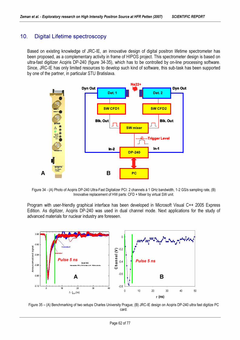
Zeman et al. - Exploratory research on High Intensity Positron Source at HFR Petten (2007) SCIENTIFIC REPORT
Page 62 of 77
-0.8
-0.6
-0.4
-0.2
0
0 10 20 30 40 50
τ (ns)
Chan
nel (V
)
CH1
Pulse 5 ns Pulse 5 ns
A B
10. Digital Lifetime spectroscopy
Based on existing knowledge of JRC-IE, an innovative design of digital positron lifetime spectrometer has been proposed, as a complementary activity in frame of HIPOS project. This spectrometer design is based on ultra-fast digitizer Acqiris DP-240 (figure 34-35), which has to be controlled by on-line processing software. Since, JRC-IE has only limited resources to develop such kind of software, this sub-task has been supported by one of the partner, in particular STU Bratislava. Figure 34 - (A) Photo of Acqiris DP-240 Ultra-Fast Digitalizer PCI: 2 channels á 1 GHz bandwidth, 1-2 GS/s sampling rate, (B)
Innovative replacement of HW parts: CFD + Mixer by virtual SW unit. Program with user-friendly graphical interface has been developed in Microsoft Visual C++ 2005 Express Edition. As digitizer, Acqiris DP-240 was used in dual channel mode. Next applications for the study of advanced materials for nuclear industry are foreseen. Figure 35 – (A) Benchmarking of two setups Charles University Prague; (B) JRC-IE design on Acqiris DP-240 ultra fast digitize PC
card.
SW mixer
Dyn Out
Trigger Level
PC
DP-240
Blk. Out
SW CFD2
Det. 1
Na22+
Blk. Out
SW CFD1
Det. 2Dyn Out
In-1In-2
SW mixer
Dyn Out
Trigger Level
PC
DP-240
Blk. Out
SW CFD2
Det. 1
Na22+
Blk. Out
SW CFD1
Det. 2Dyn Out
In-1In-2
SW mixer
Dyn Out
Trigger Level
PC
DP-240
Blk. Out
SW CFD2
Det. 1
Na22+
Blk. Out
SW CFD1
Det. 2Dyn Out
In-1In-2
SW mixer
Dyn Out
Trigger Level
PC
DP-240
Blk. Out
SW CFD2
Det. 1
Na22+
Blk. Out
SW CFD1
Det. 2Dyn Out
In-1In-2
A B

Zeman et al. - Exploratory research on High Intensity Positron Source at HFR Petten (2007) SCIENTIFIC REPORT
Page 63 of 77
Introduction After the development of fast analog-to-digital converters (ADC) and lowering the prices of the devices with these chips, a new era of the digital measurements systems started. Positron lifetime spectroscopy with measurements in pico-second area is one of the prime candidate to use this new technology. There are more possibilities to get fast digital measurement systems. Digital devices with Giga sampling (GS) rates can be obtained as standalone devices (Tectronix, Agilent scopes) or as a computer digitiser cards (Acqiris, GaGe, Ztec). Software supplied by digitiser card vendors permit simple functions like waveform digitising and storing into file, calculating FFT, wave displaying, digitiser and hardware trigger settings, etc. To use card in advanced measurement systems, which need difficult signal transformation you have libraries for external programs like Matlab and LabView. Another possibility is to develop your own standalone software. In this case you can use libraries for programming languages as Microsoft Visual C, Visual Basic, or Linux GCC. Standalone software is the best possibility for time critical applications with high performance. Main purpose The key goals of new software development are following: (a) Direct time extraction from pulses captured by ADC card. Instead of storing all captured data from digitiser card and offline data processing, in our case the data are processed directly after acquisition. Only data belonging to positron born and annihilation are processed in time extraction module. This condition was chosen to eliminate external hardware for digitiser triggering, which is needed in other digital PAS measurement systems [42,43]. (b) Modular concept - the software is programmed in C++ where all parts are objects which can be upgradeable for using different hardware or software concepts. Software development is planned as universal software for incoming new fast digitiser cards into the nuclear instruments. At this time there are digital scopes with sampling rates > 20 GS/s. Their price is too high, but it was the same situation with 2GS/s digitiser cards in the past. Our purpose is to develop software, which is designed to exploit possibility of new hardware in the future too. (c) User friendly interface proper for educational purpose and different users access levels support. Students need to change the sample and restart measurement, while a technician can change CFD and ADC settings in case of running experiment. Moreover, software developer has another debug outputs available for further software development. Different users access levels in software avoid a misguided utilization and wrong program settings. (d) Low cost for development tools cost-free or GNU software tools are used: Scilab as Matlab alternative for signal processing research. However for main development of the software the Microsoft Visual C++ Express edition tool was chosen due to good compatibility of the digitiser programming library with this compiler (Acqiris DP240). (e) Output file format suitable for J. Kansy’s LT fitting programme [44]. LT 9.0 is used in our labora-tory by students. There are good experiences with using this fitting program. Therefore histogram out-put file format is compatible with this well known fitting program. Software concept According to the block diagram in the figure 36, signals from start and stop fast scintillation detectors are captured separately by the digitiser card. The acquisition part is responsible for proper Analog to Digital Converter (ADC) settings and achieving input waveform signals from two scintillator detectors. The start detector fast dynode pulses from the 1278keV compton edge fit the digitiser full scale range and the pulses from 511 keV edge fit digitiser full scale range in stop detector. Due to lower start events count-rate, start detector input channel is set as trigger source. The second condition for proc-essing input data in next

Zeman et al. - Exploratory research on High Intensity Positron Source at HFR Petten (2007) SCIENTIFIC REPORT
Page 64 of 77
Constant Fraction Discriminator (CFD) module is occurrence of stop signal in maximum time interval after start signal. This maximum time interval is typically 50 ns and is same as the histogram time scale. When input conditions for start and stop signal are fulfilled, data are proc-essed by next CFD module, where exact time information is extracted from digitised waveforms. There are few concepts how to extract this time information from digitised signal [44,45]. As a start point in software development we chose a simple linear approximation with minimal processing and pro-gramming requirements. This approximation is shown in next section. Time difference between start and stop signal is added into histogram in the followed histogram part. After successful lifetime storing in histogram the next annihilation event can be processed. And this process is repeated until enough events in histogram are counted. The last part of the software is out-put module which is responsible for storing measurement results into output file or displaying results on the screen as histogram graph.
Figure 36 – Digital positron lifetime spectrometer - block diagram Time extraction In CFD module a simple linear approximation for time extraction was used. The method is based on digital constant fraction definition. As first we choose constant fraction voltage U(tx), which can be performed experimentally to get minimum walk. The software is looking for the samples in leading edge of the pulse between whose constant fraction voltage is applied (Figure 37). Time belonging to constant fraction voltage is then solved as following:
−−+= )1()2(
)1()(*)1()(tUtUtUtxUTntnxt (10.1)
where, t(nx) is the measured event time T is sampling period (in our case T=1ns, sampling rate 1GS/s) t(n1) is the time after sampling is started U(tx) is the constant fraction voltage value U(t1) is the sampled voltage in leading edge sample before constant fraction U(t2) is the sampled voltage in leading edge sample after constant fraction

Zeman et al. - Exploratory research on High Intensity Positron Source at HFR Petten (2007) SCIENTIFIC REPORT
Page 65 of 77
Figure 37 - CFD with simple linear pulse approximation. There is also possibility to use other type of signal approximations e.g. gausian, cubic extrapolation, etc. since the user can adjust also this parameter. Graphical User Interface Microsoft Visual C++ Express edition was chosen for development of graphical user interface (GUI). While MFC is not part of the free Visual C++ edition, another free Win32++ framework was used. Figure 38 shows a main DigiPAS LT application window including the dialog setup of digitiser card. DigiPAS LT graphical user interface allows to adjust and view all measurement parameters in user-friendly environment.
Figure 38 - Win32++ framework with ADC card setup dialog

Zeman et al. - Exploratory research on High Intensity Positron Source at HFR Petten (2007) SCIENTIFIC REPORT
Page 66 of 77
Summary The optimisation and testing of the software for ultra-fast digitizer is undergone for further applications in positron lifetime spectroscopy. The specified goals and main steps to development a high-quality software for digital lifetime spectroscopy have been achieved. However, there is pending a lot of work related to the testing and validation of designed software for real-time measurement. Therefore the further milestone will be to collect the high-quality experimental results, which can be fully comparable with results from fast analogue lifetime systems.

Zeman et al. - Exploratory research on High Intensity Positron Source at HFR Petten (2007) SCIENTIFIC REPORT
Page 67 of 77
Chapter (xi)
ADVANCED APPLICATIONS OF POSITRON TECHNOLOGY
by A.ZEMAN

Zeman et al. - Exploratory research on High Intensity Positron Source at HFR Petten (2007) SCIENTIFIC REPORT
Page 68 of 77
11. Advanced applications of positron technology
After discovery of the positron, new techniques became soon very important probe in domain of condensed matter. However, their application has been very limited by the broad energy distribution of positrons produced by beta-decay. It wasn't until the 1970's that technology had advanced sufficiently to allow the production of relatively intense, monoenergetic beams of slow positrons. The use of positron beams allows the study of surfaces, as well the investigation of defects in a depth-profiled mode. In particular, slow positron beams are currently used in variations on standard condensed matter analysis techniques, as well as in techniques which are unique to the positron field. Some of the many probes currently in use which exploit the properties of positrons include: Low-Energy Positron Diffraction (LEPD), Positron annihilation-induced Auger-Electron Spectroscopy (PAES), REemitted-Positron Energy-Loss Spectroscopy (REPELS), Angular Correlation of Annihilation Radiation (ACAR), Doppler Broadening Spectroscopy (DBS), Positron Annihilation Lifetime Spectroscopy (PALS), and Reemitted-Positron or -Positronium Spectroscopy (RPS). In particular, Slow-Positron Beams (SPB) are being used today in an ever-increasing variety of fundamental and applied studies in atomic physics and condensed matter. Pulsing low energy positron system The method of the timing with beams involves collecting the positrons in equally separated (in time) bunches. This has been done by Mills (1980a) using magnetic mirrors to bunch a nominally DC magnetically guided beam, attaining so far a best reported time resolution of ~8 ns (Mills, Pfeiffer, Platzman, 1983). A new system being developed by the Munich group (Schödlbauer et. Al 1985, 1987) combines similar magnetic bunching techniques with a high-chopper, which they expect will yield an ultimate time resolution of around 100 ps. This system has so far been tested to a resolution of ~200 ps. Bunched positron beams can also be produced at LINAC’s, where the pulsed electron beam automatically results in bunches ranging from a few ns to few µs in width (Howell. Fluss, Rosenberg, Meyer, 1985). Pulsing low energy positron system, as a progressive positron annihilation technique, achieved huge developed in the last two decades years. The aims of improvement of existing (conventional) positron beams were oriented to following factors: (a) Higher positron generation rate (implementation of innovative positron sources) (b) Bunching of beam (sharply-defined start signal) (c) Possibility of positron energy modulation (d) Increase of peak-to-background ratio (important in case of irradiated materials). (e) Improved positron moderation stage (f) Depth scanning studied (near surface region). The description of the function of base segments starting by source is presented shortly. The characteristics of such system are summarized in table 13.

Zeman et al. - Exploratory research on High Intensity Positron Source at HFR Petten (2007) SCIENTIFIC REPORT
Page 69 of 77
Table 13 – Overview of parameters for 3rd generation of PLEPS systems. , Those features offer the chance to analyse the information about microstructural changes, mainly about the type and concentration of defects. The design and technical implementation of such facility were many specific problems, which had to be solved in the past to avoid disturbing factors connected to the use of this technique. The most progressive way “how to achieve” a strong positron source was positron beam creation according to reactions on target which would be permanent treated by particles produced by nuclear reactor. Such created high intensity positron generator is necessary for the effective pulsed system. In frame of the HIPOS concept the following main parameters can be achieved: (i) Beam intensity on the level of about 1010 – 1011 e+/s. (ii) Pulses of positron in low energy region 1-30 keV. The replacement of conventional positron source (22Na typically) by reactor or LINAC-based source, will significantly improve some parameters due to higher intensity of the beam itself. This offers to adjust important parameters more precisely with respect of reasonable measurement time. A beam diameter on the level of about 2 mm is better that in Helsinky or Delft, where 3 mm can be achieved [46]. Moreover, further R&D on detectors and electronics can still improve the resolution of the system (FWHM). The count rate and peak to background will be improved substantially. General concept of pulsing positron system (a) Source, the conventional NaCl dried drops with the 22Na isotope with activity of 1.1 GBq was used. 22Na source was connected to 200V potential. On the left side from the source was UHV chamber for moderator preparation. Source and prebuncher configuration are basically the same as in the previous version [47]. (b) Well annealed tungsten transmission moderator (single crystalline foil < 100 >, thickness 1 µm) is used to generate the low energy positrons. The moderator can be annealed in situ with an electron gun. (c) The bc-beam after the moderator is prebunched with a sawtooth buncher device which is explained in detail in [48,49]. The measured time distribution of the prebunched positrons at the entrance slit of the
chopper is about 2 ns (FWHM). This width is mainly caused by the energy spread (∆E ≈ 0.4 eV (FWHM)) of the moderated positrons [50]. The positron beam signal is moderated in next electronic units.
Characteristics Parameter value RF-power electronics operated at an overall master frequency (for all bunching and chopping components) 50 MHz Up to ten samples could be stored in a magazine and transferred under vacuum conditions to the measuring position 10-6 Pa Variable sample temperature 30K and 600K Primary source activity (22Na) 30 mCi (1.11 GBq)
(1mCi = 37 MBq) Peak-to-Background ratio (at count rate of up to 4 kHz) 3000:1 Determined beam diameter 2 mm Resolution of pulsing plus detector system (FWHM) 250 ps

Zeman et al. - Exploratory research on High Intensity Positron Source at HFR Petten (2007) SCIENTIFIC REPORT
Page 70 of 77
A B
(d) The positrons which travel in a longitudinal magnetic guiding field of about 7mT are deflected by 90o and enter then the new chopper device with an energy of 200 eV (see figure 39). This chopper is a double plate system with an external resonator, positioned outside the vacuum system This chopper is located far away upstream from the sample/detector position in order to minimize the background caused by annihilating positrons at the chopper plates. Figure 39 – Schematic view of (A) chopper and (B) double gap-buncher. (e) After a second 90° bend the pulsed positrons enter the new 50 MHz buncher. This device is in principle the classical double gap buncher with a travelling time of 10 ns for the positrons through the drift tube.
When compared to a λ/4 coaxial resonator, the double gap resonator is preferable due to the shorter length and the lower RF-power consumption because of two bunching gaps. The RF-power is fed in by a coupling loop and a pick-up loop is used for control and regulating purposes. A fine tuning can be made by an adjustable plunger. This type of buncher turned out to be very stable, no readjustments or permanent fine-tuning is necessary. High-frequency amplitudes of some 100 V are needed. The overall master frequency of all bunching and chopping components is 50 MHz. The master oscillator and the RF-power amplifiers for the chopper and the buncher are newly designed with modern electronic components. (f) After the buncher, the positrons enter a drift tube. This drift tube is necessary in order to adjust the travelling time of the positrons independent of their final energy. (g) The following accelerator is configured as a simple voltage divider. The large overlapping accelerator rings are specially shaped to obtain the optimum beam optics. (h) After the accelerator the positrons pass a Wien filter which allows suppressing back reflected positrons from the sample in order to minimize disturbing side peaks in the lifetime spectra. (i) The following Faraday cage, which has been enlarged as compared to the previous version, is separated from the vacuum system above by a differential pumping stage. With a vacuum of the order of 10-7 mbar in the region of the high frequency components it is possible to achieve a vacuum of about 10-9 mbar in the sample region. The background-suppression of back-scattered positrons is presented in figure 40.

Zeman et al. - Exploratory research on High Intensity Positron Source at HFR Petten (2007) SCIENTIFIC REPORT
Page 71 of 77
Figure 40 - The background-suppression of back-scattered positrons. (j) The sample station is also newly designed and rebuilt. The distance between sample and detector (BF2) is further reduced. A new generation of PLEPS system has been designed for the use where the positron source is initiated by nuclear reactor. The last PLEPS IV is shown in figure 41. Positrons are flying into pre-buncher with kinetic energy 20eV. Old system was designed for positrons accelerated with positive potential on the moderator above 22Na source to 200eV.
Figure 41 - Schematic view of the latest version of the 4rd generation of PLEPS system.
Chopper
FRM II 20eV p
Vorbuncher
Buncher
Drift tube
Accelerator
Wien filterFaradaycage
SpecimendetektorCryostat
e+ Pre-buncher

Zeman et al. - Exploratory research on High Intensity Positron Source at HFR Petten (2007) SCIENTIFIC REPORT
Page 72 of 77
Low positron kinetic energy needs changes in prebuncher and chopper. The simplest solution of this problem is to accelerate 20eV positrons with additional potential added to inner prebuncher and chopper parts. Besides this solution need additional shielding of the positron beam from outer parts of the system which are on the ground potential, which if not shielded decelerate positrons. This requires changes in chopper and in 90° deflecting bend. Rest parts of the system are already separated from ground so could stay unchanged. Performance of Positron Beams The expected performance of PLEPS after implementation at the reactor as an effective positron source is summarised in table 14 [51,52]. The second column gives the expected values of important system parameters in the standard operating condition, which will be sufficient for many purposes. The third column shows expected limiting performances, which sometimes may be only achieved at the expense of other parameters, e.g. an extended time-window or an improved time-resolution will entail a reduced count-rate. Conversely, the increase in the magnetic field strength at the entrance of PLEPS causes an adiabatic beam-compression. The expected reduced beam diameter of about 1 mm will improve the overall performance of the system, since a narrower beam will cause less deviations of the device from the ideal behaviour. An increase in the beam energy-range to implantation energies higher then 22 keV will be possible only with an additional rf-accelerator as described in [51]. This would require considerable changes in the system, and is therefore not envisaged in the near future [52].
Table 14 - Expected performance of the pulsed low energy positron system at research reactor.
Standard Limit Event-rate 5× 10⁵ s-1 ∼ 106 s-1 DB event-rate ≤ 104 s-1 AMOC event-rate ∼ 103 s-1 Time-resolution 240 ps ≥ 150 ps Time-window 20 ns ≤ 1 µm Peak-height to background ratio > 104 ≤ 106 Size of beam-spot 1-2 mm > 0.5 mm Beam energy 0.5-22 keV 0.05- 0.5 keV
22- 42 keV In addition, to increase the utility of PLEPS as a tool for materials science, some experimental conditions can be controlled. The temperature of the sample may be varied over the range from 30 K to 600 K. The sample may also be illuminated with light from 200 nm to 2000 nm. An electron gun for heating and a sputter gun are available for in situ treatment of the specimens. Together with the good system performances this will make PLEPS not only a unique tool for non-destructive defect profiling, but also for investigating dynamical processes or large sample series with many systematically variable parameters. By installation of the PLEPS system at reactor based positron source the count-rate could increase by a factor of at least 103. This enables drastically reduced acquisition times at enhanced statistics. As a result more and better spectra can be measured in shorter time. Moreover, in the future PLEPS will offer simultaneously lifetime, Doppler-broadening and AMOC measurements.

Zeman et al. - Exploratory research on High Intensity Positron Source at HFR Petten (2007) SCIENTIFIC REPORT
Page 73 of 77
High resolution defect analysis To perform micro-analysis and thin-film analysis of defects, we are currently developing an intense, pulsed, sub-micron size positron beam (positron micro-probe) capable of 3-dimensional maps of buried defects and defect profiling in thin films and at interfaces (figure 42). This instrument can be used for either spot analysis or in scanning mode to provide a three-dimensional map of defect concentrations. High current beam and positron microprobe will provide high data rates while detecting and identifying depth-dependent concentrations of vacancies, voids, gas-filled voids and other negatively charged defects at typical depth and lateral resolutions of less than 0.1 micro-meter. Figure 42 - The positron micro-probe is a small, high-intensity, pulsed, variable-energy positron beam. Defect location is determined by controlling the positron beam size and energy to confine the positrons to a volume of scale ~ r2d, where r ~ 1 µm and d varies up
to ~ 10 µm. Positron micro-probe systems The detailed information about the actual defects is urgently needed in all kinds of materials science. But the most powerful imaging device, the transmission electron microscope (TEM), usually is unable to provide sufficient information at defect sizes below a few nm [53-56]. As an alternative, the methods of nuclear condensed matter physics have been introduced, e.g. positron annihilation. Although in these methods matter is probed at the atomic scale, the information is still incomplete since the probed volume elements are randomly distributed over a specimen volume of typically 1–106 mm3. The ratio of more than 1019 between specimen volume and microscopic probed volume henceforth will be called the relevance gap (RG). The smaller the RG the better, because the remaining RG must be closed by combining results from various experiments and by invoking theory and computer simulations. All these time consuming procedures are possible sources of error and doubt. The exclusive advantage of positron annihilation is a RG which is markedly smaller than in any other method, because positrons are trapped at defects. At 1 ppm defect concentration, the RG is reduced to about 1013. A further reduction has been achieved by means of ordinary positron beams, where one dimension of the specimen volume is reduced by 103 resulting in a RG of >1010. In positron microscopes/microprobes, the RG is further diminished by means of the narrow focus of a positron micro-beam, which reduces drastically the actually sampled specimen volume. As a microprobe the micro-beam provides a local analysis of the defects. As a microscope it delivers an image of the variation of the annihilation characteristics. During the last decade we have constructed the first pulsed positron micro-beam. It has been christened the scanning positron microscope (SPM) [57]. Positron microscopy
D et ect or
D et ect or
D et ect or
D et ect or

Zeman et al. - Exploratory research on High Intensity Positron Source at HFR Petten (2007) SCIENTIFIC REPORT
Page 74 of 77
Recently a research on a new positron microscope was done at Military University in Munich (Germany). The first results present the image of a surface scanned by such new new technique based on positrons (know as anti-matter probe). The outcomes shows that positrons can see defects better than either optical or electron beam microscopes. Positrons also provide information about the type of defect present. The scanning positron microscope (SPM) may soon be available as a powerful tool for probing many different materials. There was clear demonstration that thought positrons might give high quality images of the defects in semiconductor surfaces can be achieved. Because of the positive charge, positrons are drawn to so-called vacancies, locations within a crystal or on its surface where a positively charged nucleus is missing. Without the nucleus, there are fewer electrons in the neighborhood, so a positron can survive longer before colliding and annihilating with its electron counterpart. By measuring a positron's survival time inside a section of material. The scientist believed they could achieve unprecedented sensitivity to defects. "Positrons can detect defect concentrations of 1 part-per-million (ppm),, which any other methods have not such level of sensitivity [58]. Analysed silicon wafer was etched with a simple pattern of defects inside the chamber of their microscope. They began by scanning the surface with electrons to create an image of the pattern, a procedure similar to that for a standard electron microscope. Then they selected the most interesting regions of the surface to probe with positrons. The positrons, which came from a radioactive sodium source, passed through a series of electric fields that homogenized their energies and bunched them into short pulses. Further testing passed through another series of fields that accelerated the pulse to a specified energy before focusing it into a 2-µm dot on the silicon surface. By measuring the time between the pulse and the photon flash of electron-positron annihilation the team was able to map the defect regions. Interesting results were found by positrons that lodged inside defects avoided annihilation for twice as long as those in others regions. By scanning the beam across the surface, they created an image of the defect pattern in the wafer. The SPM can also give information on the type of defect--information that no other technique can provide. A positron survives for different lengths of time inside different kinds of defects, so by analyzing a spectrum of positron lifetimes, you can determine the types of defects present in a material. Future developments on improvement of such device is very promising not only for the semiconductor industry. Figure 20 - Positron picture. An electron microscope image (left-grey) contains less information on a test pattern of surface defects
than that of the new scanning positron microscope (right-blue) [58].

Zeman et al. - Exploratory research on High Intensity Positron Source at HFR Petten (2007) SCIENTIFIC REPORT
Page 75 of 77
References [1] K.A.Marsh et. al., Positron beam propagation in a meter long plasma channel, Proceedings of the 2003 Particle Accelerator Conference, 731-733 (2003) [2] C.Hugenschmidt et al., Nucl. Instr. And Meth. in Phys. Res. B 192 (2002) 97-101 [3] Tables of Isotops 7th ed. C.M.Lederer,V.S.Shirley, J.Wilson & Son Inc., New York- Chichester-Brisbane-Toronto, 533 (1978) [4] http://wwwndc.tokai.jaeri.go.jp, Japanese standard library for fast breeder reactors, thermal reactors, fusion neutronics and shielding calculations, and other applications [5] E.Lohrmann, Hochenergiephysik, Teubner Studienbücher, 1981 [6] Alex H. Weiss, S. Yang, H. Q. Zhou, E. Jung, A. R. Koymen, S. Naidu, Gerhard Brauer and Martti J. Puska , Appl. Surf. Sci. 85 (1995) 82-86 [7] M.J.Puska, R.M.Nieminen, Rev.Mod.Phys. 66 (1994) 3 [8] A. Vehanen, et al., Phys. Rev. B 32 (1985) 7561-7563 [9] http://www.positronannihilation.net [10] A.P. Mills, Further improvements in the efficiency of low-energy positron moderators, Applied Physics Letters 37 (1980) 667-668 [11] J Störmer et al , J. Phys.: Condens. Matter 8 (1996) L89-L94 [12] E.Keneth, Propulsion And Power With Positrons, NIAC Meeting 24 March 2004, US Air Force National Laboratory [13] M.J. Berger, J.H. Hubbell, S.M. Seltzer, J. Chang, J.S. Coursey, R. Sukumar, and D.S. Zucker, XCOM (Photon Cross Sections Database) NIST Standard Reference Database 8 (XGAM), http://physics.nist.gov [14] H.Schut, Performance of the Delft high intensity positron beam POSH, Int. Sci. Work. - Application of high intensity positron beam techniques and digital lifetime positron spectroscopy in material science, 17-18.11.2005 The Netherlands, EUR-22182EN (2006) [15] C.V.Falub, The Delft intense slow positron beam 2D-ACAR facility for analysis of nanocavities and quantum dots, DPU Science (2002) ISBN 90-407-2337-0 [16] J. Ahlf, A.Zurita, HFR Petten – Characteristics of the installation and the irradiation facilities, EUR 15151 EN, 1993 [17] N.G.Chrysochoides, M.R.Cundy, P. von der Hardt, R.J.Swanenburg de Veye, A.Tas, HFR Petten – Replacement of the reactor vessel and connected components (overall report), EUR 10194 EN, 1985 [18] Operation and Utilization of the High Flux Reactor, Annual report 2005, EUR 22297 EN, 2006 [19] P.J.Schultz, K.G.Lynn, Rev. Mod. Phys 60 (1980) 3 [20] C.V.Falub et al. Nucl. Instr. Meth. A 488 (2002) 478-492 [21] ENDF-201, ENDF/B-VI Summary Documentation, Report BNL-NCS 17541, P.F. Rose (Ed.) 4th Edition (1996) [22] J.A. Hendriks, N.A. Hanan, J.R. Deen and J.E. Matos, Validation of the calculational model applied in the HFR HEU/LEU conversion studies, Report 25138/01.40881/C revB, NRG Petten (20 June 2002) [23] A. Hogenbirk, HIPOS - validation of radiation transport calculations, Report 21748/06.74513/C, NRG Petten (June 2006) [24] S.C. van der Marck, The calculation of radiation heating in the HFR, NRG Petten, Report 25138/05.70297 (2005) [25] M.C. Duijvestijn et al., OWL-O.1 Nuclear data library for borehole logging, NRG Report 21307/04.58684/C, 2004; M.C. Duijvestijn, Results of the Computalog simulations, Note K5042/05.66095, 5 April 200 [26] F.C. Maienschein, Fission product gamma rays, in: Engineering compendium on radiation shielding, R.G. Jaeger (Ed.), Springer, Berlin, 1968 [27] J.S. Hendricks, G.W. McKinney, L.S. Waters, T.L. Roberts, H.W. Egdorf, J.P. Finch, H.R. Trellue, E.J. Pitcher, D.R. Mayo, M.T. Swinhoe, S.J. Tobin, J.W. Durkee, F.X. Gallmeier, J.-C. David, W.B. Hamilton and J. Lebenhaft, MCNPX extensions, version 2.5.0, Report LA-UR-05-2675, Los Alamos National Laboratory, April 2005

Zeman et al. - Exploratory research on High Intensity Positron Source at HFR Petten (2007) SCIENTIFIC REPORT
Page 76 of 77
[28] A.Hogenbirk, HIPOS – validation of radiation transport calculations, NRG Petten, Report 21748/06.74513/C FAI/AH/MH, June 2006 [29] A.Paardekooper, Modification activation rate measurement, Note 21748/05.70296, NRG Petten (15 November 2005). [30] A.Hogenbirk, Calculation of power distribution in HFR position C9, Note 21748/06.71566, NRG Petten (19 January 2006) [31] S.M.Willemsen, Bepaling effect op koeling Be-plug en vatwand bij plaatsing monitorset t.b.v. HIPOS project, Note 21748/05.70608, NRG Petten (1 December 2005). [32] E.Z.Muller et al., Development of a core follow calculational system for research reactors in Proc. 9th Pacific Basin Nuclear Conference, Sydney, Australia, May 1-6, 1994 [33] MCNP - A General Monte Carlo N-Particle Transport Code, Version 4C, Report LA-13709-M, Los Alamos National Laboratory, J. F. Briesmeister (Ed.) April 2000 [34] J.S.Hendricks, MCNP4C3 - 3/22/01, Report X-5:RN(U)-JSH-01-17, Los Alamos National Laboratory (13 April, 2001) [35] ENDF-201, ENDF/B-VI Summary Documentation, Report BNL-NCS 17541, P.F. Rose (Ed.) 4th Edition (1996) [36] The JEF-2.2 Nuclear Data Library, JEFF Report 17, NEA Paris (April 2000) [37] W.E. Freudenreich, Neutron Activation Cross Section Library DOSCROS2001, Report 20689/01.40537/I, NRG Petten (26 April 2001) [38] D.B.Pelowitz, MCNPX User’s Manual, Version 2.5.0, LA-CP-05-0369, Los Alamos National Laboratory, USA (2005) [39] S.Agostinelli, et al., GEANT4 - a simulation toolkit, Nuclear Instruments and Methods in Physics Research, A 506 (2003) [40] J.Blachot, Nuclear Data Sheets 97, 593 (2002), www.nndc.bnl.gov/useroutput/AR_85572_1.htm, accessed on 25 July 2007 [41] C.Hugenschmidt, G.Kögel, R.Repper, K.Schreckenbach, P. Sperr, B.Strasser, W.Triftshauser, Nucl. Instr. And Meth. in Phys. Res. B 198 (2002) 220-229. [42] J.Nissilä, K. Rytsölä, R. Aavikko, A Laakso, K. Saarinen, P. Hautojärvi. Nucl. Inst. and Meth. A 538 778-789 (2005) [43] H. Saito, Y. Nagashima, T. Kurihara, T. Hyodo Nucl. Instr. and Meth. A 487, 612-617 (2002) [44] J. Kansy, Nucl. Instr. and Meth. A 374, 235-244 (1996). [45] F. Bečvář, J.Čížek, I. Procházka and J.Janotová, Nucl. Instr. and Meth. A 539, 372-385 (2005). [46] F. Reurings, Current status of Helsinky positron beam. In: CD-room proceedings of the International Scientific Workshop on “The application of high intense positron beams and digital lifetime spectroscopy in material science”. November 17-18, 2005, Bergen, The Netherlands [47] W.Bauer-Kugelmann, P.Sperr, G.Kögel, W.Triftshäuser, Mat. Sci For 363-365 (2001) 529-531 [48] W.Bauer-Kugelmann, Technische Weiterentwicklungen am gepulsten Positronenstrahlsystem PLEPS, Universität der Bundeswehr München, Fakultät für Luft- und Raumfahrttechnik, Institut für Nukleare Festkörperphysik, Disertation, 17.3.2000 [49] J.Störmer, Positronenlebensdauerspektroskopie in oberflächennahen Bereichen von Silizium- und Siliziumkarbid-Halbleiterstrukturen mit monoenergetischen Positronen, Universität der Bundeswehr München, Fakultät für Luft- und Raumfahrttechnik, Institut für Nukleare Festkörperphysik, Disertation, 8.12.1995 [50] P. Wilutzki, Verbesserung und Erweiterung des gepulsten Positronenstrahlsystems für temperaturabhängige Lebensdauermessungen von Positronen in Festkörpern, Universität der Bundeswehr München, Fakultät für Luft- und Raumfahrttechnik, Institut für Nukleare Festkörperphysik, Disertation 11.5.1994 [51] W. Egger, P.Sperr, G. Kögel, G.Dollinger, The pulsed low energy positron system (PLEPS) at the Munich research reactor FRM II. Proceedings from ICPA-14, 22.-28.7.2006, Hamilton, Canada [52] Ch. Hugenschmidt, The NEPOMUC positron source at FRM II reactor in Munich. Proceedings from ICPA-14, 22.-28.7.2006, Hamilton, Canada

Zeman et al. - Exploratory research on High Intensity Positron Source at HFR Petten (2007) SCIENTIFIC REPORT
Page 77 of 77
[53] R.Suzuki, Y.Kobayashi, T.Mikado, H.Ohgaki, M.Chiwaki, T.Yamazaki, T.Tomimasu, Japan J., Appl. Phys. 303 B, 532 (1991). [54] D.Segers, J.Paridaens, M.Dorikens, L.Dorikens-Vanpraet, Nucl. Instr. Meth. in Phys. Res. A 337, 246 (1993). [55] A.Van Veen, H.Shut, P.E.Mijnarends, L.Seijbel, P.Kruit, SLOPOS-5, Jackson 6-10 August (1990). [56] D.Taqqu, Helv. Acta 63, 442 (1990). [57] P. Perez, A. Rosowsky / Nuclear Instruments and Methods in Physics Research A 532 (2004) 523–532 [58] A. David, G. Kögel, P. Sperr, and W. Triftshäuser, Lifetime Measurements with a Scanning Positron Microscope, Phys. Rev. Lett. 87 (2001) 067402

European Commission EUR 23662 EN – Joint Research Centre Title: High Intensity Positron Source at HFR Author(s): A.ZEMAN and L.DEBARBERIS Luxembourg: Office for Official Publications of the European Communities 2009 – 77 pp. – 21 x 27.7 cm EUR – Scientific and Technical Research series – ISSN 1018-5593 Abstract With the wide-expansion of positron annihilation techniques into the various research fields there is a strong demand for high intensity positron sources, which are required for effective utilization of advanced beam systems. There are many efforts made, throughout the world, to design and set-up positron sources and beam systems with high intensity based on various principles. Such a positron source could be the basis for a series of experiments in fundamental and applied research and would also be a prototype source for industrial applications, which can concern not only in the field of matter characterization at the nanometer scale. Phenomena involving positrons are important in many fields of applied science, as medicine, biology, physics, energy, etc. The laboratories with low-energy positron beams are now being also used for investigation of outstanding studies of electron–positron plasma phenomena, anti-hydrogen formation, modeling of astrophysical processes, and just recently also for newly discovered Bose-Einstein condensate. However, the limitations of such studies are often due to the relative lack of suitable positron sources. Therefore, the key-outcomes of the HIPOS project include the basic design & development of such powerful experimental facility with a very high intensity positron beam based on reactor source. Proposed concept utilize a (n,gamma) and (gamma, pair) nuclear reactions within designed positron generator at High Flux Reactor (HFR) in Petten.

The mission of the JRC is to provide customer-driven scientific and technical support for the conception, development, implementation and monitoring of EU policies. As a service of the European Commission, the JRC functions as a reference centre of science and technology for the Union. Close to the policy-making process, it serves the common interest of the Member States, while being independent of special interests, whether private or national.