hiseq 2000 user guide - rikenfantom.gsc.riken.jp/.../11/hiseq2000_userguide...d.pdf · hiseq 2000...
TRANSCRIPT

HiSeq 2000User Guide
GT
GAAAAAAACAAAAAAACCCAAAAAAA
GCCGGGGGT
ATGCATGCATGCATGCATCAT
GCATGCATGCA
G
TAG
CC
FOR RESEARCH USE ONLY
™
ILLUMINA PROPRIETARYCatalog # SY-940-1001Part # 15011190 Rev D


HiSeq 2000 User Guide iii
Notice
This document and its contents are proprietary to Illumina, Inc. and its affiliates ("Illumina"), and
are intended solely for the contractual use of its customer in connection with the use of the
product(s) described herein and for no other purpose. This document and its contents shall not
be used or distributed for any other purpose and/or otherwise communicated, disclosed, or
reproduced in any way whatsoever without the prior written consent of Illumina. Illumina does
not convey any license under its patent, trademark, copyright, or common-law rights nor similar
rights of any third parties by this document.
The instructions in this document must be strictly and explicitly followed by qualified and
properly trained personnel in order to ensure the proper and safe use of the product(s)
described herein. All of the contents of this document must be fully read and understood prior
to using such product(s).
FAILURE TO COMPLETELY READ AND EXPLICITLY FOLLOW ALL OF THE INSTRUCTIONS
CONTAINED HEREIN MAY RESULT IN DAMAGE TO THE PRODUCT(S), INJURY TO PERSONS,
INCLUDING TO USERS OR OTHERS, AND DAMAGE TO OTHER PROPERTY.
ILLUMINA DOES NOT ASSUME ANY LIABILITY ARISING OUT OF THE IMPROPER USE OF THE
PRODUCT(S) DESCRIBED HEREIN (INCLUDING PARTS THEREOF OR SOFTWARE) OR ANY USE
OF SUCH PRODUCT(S) OUTSIDE THE SCOPE OF THE EXPRESS WRITTEN LICENSES OR
PERMISSIONS GRANTED BY ILLUMINA IN CONNECTION WITH CUSTOMER'S ACQUISITION
OF SUCH PRODUCT(S).
FOR RESEARCH USE ONLY
© 2010 Illumina, Inc. All rights reserved.
Illumina, illuminaDx, Solexa, Making Sense Out of Life, Oligator, Sentrix, GoldenGate, GoldenGate Indexing, DASL, BeadArray, Array of Arrays, Infinium, BeadXpress, VeraCode, IntelliHyb, iSelect, CSPro, GenomeStudio, Genetic Energy, HiSeq, and HiScan are registered
trademarks or trademarks of Illumina, Inc. All other brands and names contained herein are the
property of their respective owners.


HiSeq 2000 User Guide v
Revision History
Part # Revision Date Description of Change
15011190 D May 2010 Corrected Sequencing Kit box 1 and box 2 contents.
Updated volumes in the preparation of Multiplexing Rd2 Seq Primer for use on HiSeq.
15011190 C April 2010 Corrected reagent thawing instructions for LFN and volumes listed in the multiplexing reagent preparation instructions.
15011190 B March 2010 Updated software descriptions and workflow to HCS v1.0.
Added instructions for changing reagents during a run, and stopping, pausing, and resuming a run.
Updated reagent preparation instructions and added instructions for allocating reagents for 101 cycles.
15011190 A February 2010 Initial release.


HiSeq 2000 User Guide vii
Table of Contents
Notice. . . . . . . . . . . . . . . . . . . . . . . . . . . . . . . . . . . . . . . . . . . . . . . . . . . . . . . iii
Revision History . . . . . . . . . . . . . . . . . . . . . . . . . . . . . . . . . . . . . . . . . . . . . . . v
Table of Contents . . . . . . . . . . . . . . . . . . . . . . . . . . . . . . . . . . . . . . . . . . . . vii
List of Tables . . . . . . . . . . . . . . . . . . . . . . . . . . . . . . . . . . . . . . . . . . . . . . . . . ix
Chapter 1 Overview . . . . . . . . . . . . . . . . . . . . . . . . . . . . . . . . . . 1
Introduction . . . . . . . . . . . . . . . . . . . . . . . . . . . . . . . . . . . . . . . . . . . . . . . . . . 2
Audience and Purpose. . . . . . . . . . . . . . . . . . . . . . . . . . . . . . . . . . . . . . . . . . 3
Technical Assistance . . . . . . . . . . . . . . . . . . . . . . . . . . . . . . . . . . . . . . . . . . . 4
HiSeq Components . . . . . . . . . . . . . . . . . . . . . . . . . . . . . . . . . . . . . . . . . . . . 5
Sequencing Consumables . . . . . . . . . . . . . . . . . . . . . . . . . . . . . . . . . . . . . . . 8
HiSeq Sequencing Reagents . . . . . . . . . . . . . . . . . . . . . . . . . . . . . . . . . . . . 10
HiSeq Paired-End Reagents . . . . . . . . . . . . . . . . . . . . . . . . . . . . . . . . . . . . . 11
Multiplexing Sequencing Reagents . . . . . . . . . . . . . . . . . . . . . . . . . . . . . . . 12
Chapter 2 HiSeq Control Software . . . . . . . . . . . . . . . . . . . . . . 13
Introduction . . . . . . . . . . . . . . . . . . . . . . . . . . . . . . . . . . . . . . . . . . . . . . . . . 14
HiSeq Software Interface . . . . . . . . . . . . . . . . . . . . . . . . . . . . . . . . . . . . . . . 15
Pausing, Stopping, and Resuming a Run . . . . . . . . . . . . . . . . . . . . . . . . . . . 28
Run Folders . . . . . . . . . . . . . . . . . . . . . . . . . . . . . . . . . . . . . . . . . . . . . . . . . 32
Available Disk Space . . . . . . . . . . . . . . . . . . . . . . . . . . . . . . . . . . . . . . . . . . 34
Chapter 3 Performing a Sequencing Run . . . . . . . . . . . . . . . . . 35
Introduction . . . . . . . . . . . . . . . . . . . . . . . . . . . . . . . . . . . . . . . . . . . . . . . . . 36
Sequencing Workflow . . . . . . . . . . . . . . . . . . . . . . . . . . . . . . . . . . . . . . . . . 37
Starting the HiSeq . . . . . . . . . . . . . . . . . . . . . . . . . . . . . . . . . . . . . . . . . . . . 38
Preparing Sequencing Reagents . . . . . . . . . . . . . . . . . . . . . . . . . . . . . . . . . 39
Allocating Reagents For Shorter Runs . . . . . . . . . . . . . . . . . . . . . . . . . . . . . 41
Preparing Multiplexing Reagents. . . . . . . . . . . . . . . . . . . . . . . . . . . . . . . . . 43
Setting Up the Sequencing Run. . . . . . . . . . . . . . . . . . . . . . . . . . . . . . . . . . 44
Loading Sequencing Reagents . . . . . . . . . . . . . . . . . . . . . . . . . . . . . . . . . . 47
Loading Multiplexing Reagents . . . . . . . . . . . . . . . . . . . . . . . . . . . . . . . . . . 50
Loading a Used Flow Cell . . . . . . . . . . . . . . . . . . . . . . . . . . . . . . . . . . . . . . 52
Priming Reagents . . . . . . . . . . . . . . . . . . . . . . . . . . . . . . . . . . . . . . . . . . . . . 57
Loading a Clustered Flow Cell . . . . . . . . . . . . . . . . . . . . . . . . . . . . . . . . . . . 58

viii Table of Contents
Catalog # SY-940-1001
Part # 15011190 Rev. D
Monitoring the Run . . . . . . . . . . . . . . . . . . . . . . . . . . . . . . . . . . . . . . . . . . . 65
Preparing ICR for Read 2 . . . . . . . . . . . . . . . . . . . . . . . . . . . . . . . . . . . . . . . 70
Preparing Paired-End Reagents . . . . . . . . . . . . . . . . . . . . . . . . . . . . . . . . . . 71
Changing Reagents During a Run . . . . . . . . . . . . . . . . . . . . . . . . . . . . . . . . 73
Loading ICR for Read 2 . . . . . . . . . . . . . . . . . . . . . . . . . . . . . . . . . . . . . . . . 75
Loading Paired-End Reagents . . . . . . . . . . . . . . . . . . . . . . . . . . . . . . . . . . . 77
Chapter 4 Post-Run Procedures . . . . . . . . . . . . . . . . . . . . . . . . 81
Introduction . . . . . . . . . . . . . . . . . . . . . . . . . . . . . . . . . . . . . . . . . . . . . . . . . 82
Unloading Reagents. . . . . . . . . . . . . . . . . . . . . . . . . . . . . . . . . . . . . . . . . . . 83
Performing a Maintenance Wash . . . . . . . . . . . . . . . . . . . . . . . . . . . . . . . . . 84
Performing a Post-Run Instrument Wash . . . . . . . . . . . . . . . . . . . . . . . . . . . 89
Chapter 5 Real Time Analysis . . . . . . . . . . . . . . . . . . . . . . . . . . 93
Introduction . . . . . . . . . . . . . . . . . . . . . . . . . . . . . . . . . . . . . . . . . . . . . . . . . 94
Monitoring Runtime Statistics . . . . . . . . . . . . . . . . . . . . . . . . . . . . . . . . . . . 95
Real Time Analysis Output Data . . . . . . . . . . . . . . . . . . . . . . . . . . . . . . . . 101
Appendix A Troubleshooting . . . . . . . . . . . . . . . . . . . . . . . . . . . 105
Introduction . . . . . . . . . . . . . . . . . . . . . . . . . . . . . . . . . . . . . . . . . . . . . . . . 106
Troubleshooting. . . . . . . . . . . . . . . . . . . . . . . . . . . . . . . . . . . . . . . . . . . . . 106
Performing a Fluidics Check. . . . . . . . . . . . . . . . . . . . . . . . . . . . . . . . . . . . 107
Index . . . . . . . . . . . . . . . . . . . . . . . . . . . . . . . . . . . . . . . . 109
HiSeq 2000 User Guide ix
List of Tables
Table 1 Illumina General Contact Information . . . . . . . . . . . . . . . . . . . . . . . . . . . . . . 4
Table 2 Illumina Customer Support Telephone Numbers . . . . . . . . . . . . . . . . . . . . . 4
Table 3 Illumina Kits and Kit Contents . . . . . . . . . . . . . . . . . . . . . . . . . . . . . . . . . . . . 8
Table 4 User-Supplied Consumables . . . . . . . . . . . . . . . . . . . . . . . . . . . . . . . . . . . . . 9
Table 5 Run Folder Contents . . . . . . . . . . . . . . . . . . . . . . . . . . . . . . . . . . . . . . . . . . 32
Table 6 Allocating Reagents for Standard 101-Cycle Runs . . . . . . . . . . . . . . . . . . . 41
Table 7 Sequencing Reagent Positions (Rack A or B) . . . . . . . . . . . . . . . . . . . . . . . . 48
Table 8 Multiplexing Reagent Positions . . . . . . . . . . . . . . . . . . . . . . . . . . . . . . . . . . 50
Table 9 Paired-End Reagent Positions . . . . . . . . . . . . . . . . . . . . . . . . . . . . . . . . . . . 78
Table 10 Wash Run Times. . . . . . . . . . . . . . . . . . . . . . . . . . . . . . . . . . . . . . . . . . . . . . 84
Table 11 Expected Wash Delivery . . . . . . . . . . . . . . . . . . . . . . . . . . . . . . . . . . . . . . . 87
Table 12 Wash Run Times. . . . . . . . . . . . . . . . . . . . . . . . . . . . . . . . . . . . . . . . . . . . . . 92
Table 13 Expected Wash Delivery . . . . . . . . . . . . . . . . . . . . . . . . . . . . . . . . . . . . . . . 92
Table 14 Troubleshooting Run Problems . . . . . . . . . . . . . . . . . . . . . . . . . . . . . . . . . 106

x List of Tables
Catalog # SY-940-1001
Part # 15011190 Rev. D

HiSeq 2000 User Guide 1
Chapter 1
Overview
Topics2 Introduction
3 Audience and Purpose
4 Technical Assistance
5 HiSeq Components
8 Sequencing Consumables
10 HiSeq Sequencing Reagents
11 HiSeq Paired-End Reagents
12 Multiplexing Sequencing Reagents

2 CHAPTER 1
Overview
Catalog # SY-940-1001
Part # 15011190 Rev. D
Introduction
The Illumina HiSeq™ 2000 sequencing system combines innovative engineering with proven SBS technology to set new standards in output, simplicity, and cost-effectiveness.
The HiSeq 2000 includes the following features:
Dual Flow Cells—The HiSeq 2000 is a dual flow cell system. You can
sequence a single flow cell or two flow cells with different read lengths
simultaneously, and start and stop experiments independently.
Dual Surface Imaging—The HiSeq 2000 uses a four camera epi-
fluorescence system with cutting-edge scanning technology to enable
dual surface imaging.
High-Capacity Reagent Chiller—The HiSeq reagent compartment is a
high-capacity chiller that holds enough sequencing reagents for up to
209 cycles of sequencing on each flow cell.
Integrated Fluidics for Paired-End Runs—In addition to the sequencing
reagents, the HiSeq reagent compartment holds paired-end reagents for
each flow cell.
Dual Interface Control Options—The HiSeq software interface provides
dual controls, one for each flow cell, on a touch screen enabled monitor.
In addition, an integrated keyboard can be used for recording run
components and operating the instrument.
Real Time Analysis—The HiSeq software performs real time data
analysis on the instrument computer, which allows you to monitor
important quality metrics during the sequencing run and save valuable
downstream analysis time.
Figure 1 HiSeq 2000 Sequencing System

Audience and Purpose 3
HiSeq 2000 User Guide
Audience and Purpose
This guide describes the instrument components, software interface, safety considerations, consumables, and operational procedures for performing a sequencing run on the HiSeq. This guide also includes a detailed description of Real Time Analysis (RTA), which is part of the HiSeq Control Software (HCS).
This guide is for laboratory personnel and other individuals responsible for:
Operating the Illumina HiSeq 2000
Performing instrument and component maintenance
Training personnel

4 CHAPTER 1
Overview
Catalog # SY-940-1001
Part # 15011190 Rev. D
Technical Assistance
For technical assistance, contact Illumina Customer Support.
MSDSs
Material safety data sheets (MSDSs) are available on the Illumina website at http://www.illumina.com/msds.
Product Documentation
If you require additional product documentation, you can obtain PDFs from the Illumina website. Go to http://www.illumina.com/documentation. When you click on a link, you will be asked to log in to iCom. After you log in, you can view or save the PDF.
If you do not already have an iCom account, then click New User on the iCom login screen and fill in your contact information. Indicate whether you wish to receive the iCommunity newsletter (a quarterly newsletter with articles about, by, and for the Illumina Community), illumiNOTES (a monthly newsletter that provides important product updates), and announcements about upcoming user meetings. After you submit your registration information, an Illumina representative will create your account and email login instructions to you.
Table 1 Illumina General Contact Information
Illumina Website http://www.illumina.com
Email [email protected]
Table 2 Illumina Customer Support Telephone Numbers
Region Contact Number
North America toll-free 1.800.809.ILMN (1.800.809.4566)
United Kingdom toll-free 0800.917.0041
Germany toll-free 0800.180.8994
Netherlands toll-free 0800.0223859
France toll-free 0800.911850
Other European time zones +44.1799.534000
Other regions and locations 1.858.202.ILMN (1.858.202.4566)

HiSeq Components 5
HiSeq 2000 User Guide
HiSeq Components
HiSeq 2000 components include:
Reagent Compartment—Contains three racks of reagents required for
sequencing runs or wash solution for instrument washes.
Flow Cell Compartment—Contains the vacuum-controlled dual flow cell
stage, which holds flow cell A and flow cell B.
Fluidics Compartment—Contains integrated paired-end fluidics and
two fluidics pumps that operate independently, one for flow cell A and
one for flow cell B.
Enclosed Optics Module—Contains optical components that enable
dual surface imaging of the flow cell. The HiSeq images A, C, G, and T at
the same time using Epi fluorescence. The excitation laser beam passes
through the objective and the fluorescence is collected through the same
objective.
Status Bar—Uses three colors to indicate instrument status. Blue
indicates the instrument is running, orange indicates the instrument
needs attention, and green indicates that the instrument is ready to
begin the next run.
Figure 2 HiSeq Main Compartments
To set up a sequencing run on the HiSeq, you will access the reagent compartment and the flow cell compartment.
Flow Cell Compartment
Optics Module
Fluidics Compartment
Reagent Compartment
Status Bar

6 CHAPTER 1
Overview
Catalog # SY-940-1001
Part # 15011190 Rev. D
Reagent Compartment
The reagent compartment is a high-capacity reagent chiller that holds three reagent racks. Two of the racks hold 250 ml bottles and provide SBS sequencing reagents to flow cell A and flow cell B. The third rack holds tubes of paired-end reagents for both flow cells. This rack also holds the Index Read Sequencing Primer (optional).
The HiSeq reagent chiller is designed to maintain reagent temperature at 4°C. The reagent chiller is not intended to cool down reagents; therefore, reagents must be cooled before they are loaded onto the instrument.
Figure 3 Reagent Compartment
The reagent rack for flow cell A is located in the center position, and the rack for flow cell B is located in the far right position. Each reagent rack has numbered positions that correspond to the connection on the fluidics pump. You only need to load the reagent rack that corresponds to the flow cell you plan to sequence.
The paired-end reagent rack, to the left of racks A and B, has two rows of numbered positions, one row for flow cell A and the other for flow cell B. This rack holds multiplexing reagents and paired-end reagents.
After filled reagent racks are positioned inside the reagent compartment, you lower the sippers into the reagent bottles using the sipper handles.
Two fluidics pumps in the fluidics compartment, one for each flow cell, direct reagents through the fluidics lines to the flow cell, and then deliver waste to the waste bottle.
Reagent Rack for Paired-End
and Multiplexing Reagents
Reagent Rack for Flow Cell BReagent Rack for Flow Cell A
Sipper Handles

HiSeq Components 7
HiSeq 2000 User Guide
Flow Cell Compartment
The flow cell compartment houses the flow cell stage, dual thermal stations, the vacuum system, and the fluidics connections to each flow cell.
The flow cells are seated on the flow cell stage, which moves in and out of the optics module. Flow cell A is on the left, and flow cell B is on the right. Each flow cell is positioned on the flow cell holder with the inlet and outlet holes facing down, and held in place by a vacuum. The vacuum is controlled by a flow cell lever in front of each flow cell. The flow cell lever flashes green or yellow, indicating the status of the vacuum seal.
Figure 4 Flow Cell Stage
Flow Cell A Flow Cell B
Flow Cell Lever A Flow Cell Lever B

8 CHAPTER 1
Overview
Catalog # SY-940-1001
Part # 15011190 Rev. D
Sequencing Consumables
This section lists the Illumina-supplied kits and user-supplied consumables required to perform a sequencing run on the HiSeq.
Illumina-Supplied
The following Illumina-supplied kits and consumables contain components used on the HiSeq.
Table 3 Illumina Kits and Kit Contents
Illumina-Supplied Consumable Kit Contents and Description
HiSeq Sequencing Kit (200 Cycles)
Catalog # FC-401-1001
Sequencing reagents sufficient for 209 cycles of sequencing:
• Seven 250 ml bottles of sequencing reagents.
• Five tubes of reagents used to prepare ICR (Incorporation Reagent Mix).
• One 250 ml bottle of PW1 used for washing the instrument.
For more information, see HiSeq Sequencing Reagents on page 10
HiSeq Single-Read Cluster Generation Kit
Catalog # GD-401-1001
Single-read cluster generation reagents, one HiSeq single-read flow cell, and run components used on the cBot.
For more information, see the cBot User Guide.
HiSeq Accessories Kit:
• Seven single-use funnel caps for use on 250 ml reagent bottles provided in the HiSeq Sequencing Kit. For more information, see Loading Sequencing Reagents on page 47.
• Manifold gaskets for use between the manifolds and the flow cell. For more information, see Loading a Clustered Flow Cell on page 58.
HiSeq Paired-End Cluster Generation Kit
Catalog # PE-401-1001
Paired-end cluster generation reagents, one HiSeq paired-end flow cell, and run components used on the cBot.
For more information, see the cBot User Guide.
Read 2 Cluster Resynthesis Kit:
• Paired-end reagents used for Read 2 resynthesis step in paired-end runs.
For more information, see HiSeq Paired-End Reagents on page 11.
HiSeq Accessories Kit:
• Seven single-use reagent funnel caps for use on 250 ml reagent bottles provided in the HiSeq Sequencing Kit. For more information, see Loading Sequencing Reagents on page 47.
• Manifold gaskets for use between the manifolds and the flow cell. For more information, see Loading a Clustered Flow Cell on page 58.
Multiplexing Sequencing Primers and PhiX Control Kit
Catalog # PE-400-2002
Multiplexing reagents used for preparation of the Index Read in multiplexed runs.

Sequencing Consumables 9
HiSeq 2000 User Guide
User-Supplied Ensure that you have all of the following user-supplied consumables before you begin your run.
Table 4 User-Supplied Consumables
Consumable Supplier Purpose
1 M NaOH General lab supplier Instrument wash.
Alcohol wipes, 70% Isopropyl
or
Ethanol, 70%
VWR, catalog # 15648-981
General lab supplier
Cleaning the flow cell and flow cell stage.
Centrifuge tube, 250 ml Corning, catalog # 430776 Instrument and monthly maintenance wash.
Conical tubes, 15 ml Corning, catalog # 430052 Collecting and measuring waste volumes.
Conical tubes, self-standing, 50 ml Corning, catalog # 430291 Storing flow cells.
Disposable gloves, powder-free General lab supplier General use.
Lab tissue, low-lint VWR, catalog # 21905-026 Cleaning the flow cell holder.
Lens paper, 4 x 6 in. VWR, catalog # 52846-001 Cleaning the flow cell.
Pipette tips, 200 μl General lab supplier Preparing and aliquoting reagents.
Pipette tips, 1000 μl General lab supplier Preparing and aliquoting reagents.
Water, laboratory-grade Millipore SBS reagent rack, position 2.
Instrument wash.

10 CHAPTER 1
Overview
Catalog # SY-940-1001
Part # 15011190 Rev. D
HiSeq Sequencing Reagents
To perform a sequencing run on the HiSeq, you need one HiSeq Sequencing Kit (200 Cycles), catalog # FC-401-1001.
HiSeq reagents have the following features:
The 250 ml conical bottles load directly onto reagent racks.
One 200-cycle sequencing kit provides sufficient reagents for 209 cycles
of sequencing.
Reagent labels are color-coded to reduce possible errors while loading
reagents.
Each reagent contains a barcode for tracking and a human-readable
label for ease of use.
When thawed, reagents are ready for use with the exception of ICR
(Incorporation Mix Reagent), which requires mixing prior to the run.
HiSeq reagents are shipped in two boxes on dry ice. As soon as you receive your kit, promptly store the reagents at the indicated temperature to ensure proper performance.
200 Cycle Kit Box 1: Store at 2° to 8°C
Box 2: Store at -15° to -25°C
NOTEThe reagent kit ID is located on the box. During run setup, you need to enter the reagent kit ID prior to loading reagents.
200-Cycle Kit Quantity Container Size Reagent Reagent
1 250 ml bottle PW1 Wash Buffer
1 250 ml bottle ICR-200 cycles Incorporation Mix Reagent
1 250 ml bottle SB1-200 cycles High Salt Buffer
2 250 ml bottle SB2-200 cycles Incorporation Buffer
1 250 ml bottle SB3-200 cycles Cleavage Buffer
200-Cycle Kit Quantity Container Size Reagent Reagent
1 250 ml bottle CMR-200 cycles Cleavage Mix Reagent
1 250 ml bottle SMR-200 cycles Scanning Mix Reagent
1 5 ml tube LRP-200 cycles Long Read DNA Polymerase
4 5 ml tube LFN36 Long Read Nucleotide Mix

HiSeq Paired-End Reagents 11
HiSeq 2000 User Guide
HiSeq Paired-End Reagents
To perform a paired-end sequencing run on the HiSeq, you need the Read 2 Cluster Resynthesis Kit, part of the HiSeq Paired-End Cluster Generation Kit, catalog # PE-401-1001.
Paired-end cluster resynthesis reagents have the following features:
The 15 ml tubes load directly onto the paired-end reagent racks.
One kit provides sufficient reagents for one flow cell.
Reagent labels are color-coded to help reduce possible errors while
loading reagents.
Each reagent includes a barcode for tracking and a human-readable label
for ease of use.
When thawed, reagents are ready for use with the exception of HP3 (2 N
NaOH), which is diluted to 0.1 N NaOH before use.
Box 2 is shipped on dry ice. As soon as you receive your kit, promptly store the reagents at the indicated temperature to ensure proper performance.
Kit Contents Store at -15° to -25°C
NOTEThe reagent kit ID is located on the box. During run setup, you need to enter the reagent kit ID prior to loading reagents.
Quantity Container Size Reagent
1 15 ml tube HT2 (Wash Buffer)
1 15 ml tube RMX (Resynthesis Mix)
1 15 ml tube AT2 (100% Formamide)
1 15 ml tube APM2 (AMX2 Premix)
1 15 ml tube AMX2 (Amplification Mix 2)
1 15 ml tube LMX2 (Linearization Mix 2)
1 15 ml tube BMX (Blocking Mix)
1 15 ml tube HP2 (Sequencing Primer Mix 2)
1 15 ml tube HP3 (2 N NaOH)

12 CHAPTER 1
Overview
Catalog # SY-940-1001
Part # 15011190 Rev. D
Multiplexing Sequencing Reagents
To perform a multiplexed sequencing run on the HiSeq, you need the Multiplexing Sequencing Primers and PhiX Control Kit, catalog # PE-400-2002.
Multiplexing reagents have the following features:
When used on the HiSeq, one kit provides sufficient reagents for eight flow cells.
When thawed, reagents require about ten minutes of preparation time
and transfer to 15 ml tubes before loading them onto the reagent rack.
For more information, see Preparing Multiplexing Reagents on page 43.
The kit is shipped on dry ice. As soon as you receive your kit, promptly store the reagents at the indicated temperature to ensure proper performance.
Kit Contents, Box 1
Store at -15° to -25°C
Kit Contents, Box 2
Store at -15° to -25°C
NOTEThe reagent kit ID is located on the box. During run setup, you need to enter the reagent kit ID prior to loading reagents.
Quantity Container Size Reagent
1 0.5 ml tube ISP (Indexing Seq Primer)
1 0.5 ml tube Multiplexing Rd2 seq Primer
Quantity Container Size Reagent
1 1 ml tube 2 N NaOH
4 35 ml bottle Hybridization Buffer
1 40 ml bottle Wash Buffer

HiSeq 2000 User Guide 13
Chapter 2
HiSeq Control Software
Topics14 Introduction
15 HiSeq Software Interface
28 Pausing, Stopping, and Resuming a Run
32 Run Folders
34 Available Disk Space

14 CHAPTER 2
HiSeq Control Software
Catalog # SY-940-1001
Part # 15011190 Rev. D
Introduction
HiSeq Control Software (HCS) guides you through the run setup steps, and allows you to monitor your sequencing run as it progresses and assess quality statistics in real time.
HCS has the following features:
Convenient location on the instrument computer, simplifying data
management.
Easy to use graphical user interface with wizards for instrument washes,
recipe creation, reagent priming, fluidics checks, as well as a run
overview screen to monitor the run in progress.
Integrated focus feature to ensure reliable image capture.
Real time analysis (RTA), which performs base calling and provides fast
access to quality metrics. For more information, see Chapter 5, Real Time Analysis.

HiSeq Software Interface 15
HiSeq 2000 User Guide
HiSeq Software Interface
The HiSeq Control Software (HCS) interface opens to the start screen. The start screen is split into two panels, one for flow cell A and the other for flow cell B. You can set up a run for flow cell A and flow cell B in parallel using the software interface.
Figure 5 HCS Software Interface, Start Screen
Start Screen Menu
The menu button, located in the upper-left corner of the start screen, provides the following options:
View—Provides options to view the interface in full screen or in a
window, and to minimize the interface.
Tools—Accesses the Options window and the Show Log file. From the
Options window you can define default output and temp folders. Other
features listed are not yet supported in HCS v1.0. The Show Log file is a
text file used for troubleshooting.
About—Provide information about the HiSeq hardware, HCS version,
and technical support contacts.
Exit—Closes the HCS interface.
Figure 6 Menu Button
Menu Flow Cell A Interface Panel Flow Cell B Interface Panel
Activity Indicators

16 CHAPTER 2
HiSeq Control Software
Catalog # SY-940-1001
Part # 15011190 Rev. D
Activity Indicators
The start screen contains a series of activity indicators in the lower-right corner of the screen. They tell you which activity the instrument is performing and are used throughout the interface. From left to right, they represent the X, Y, and Z motors, electronics functionality, the camera, the fluidics system, and processing functions.
Figure 7 Activity Icons
Start Screen Options
Each run begins at the start screen and returns to the start screen after the run is complete. From the start screen, you have three options: Sequence, Wash, and Check.
Figure 8 Start Screen Options
Sequence—Select Sequence to begin setting up your sequencing run.
The software guides you through the run setup steps. For more
information, see Run Configuration Screens on page 17.
Wash—Select Wash to initiate a post-run instrument wash. Perform a
wash at the beginning of a run if the instrument has been idle for one day
or more. Two wash options are available:
• Post-Run Wash—The post-run wash flushes water through the
system for either flow cell A or flow cell B. Use either the post-run
wash or the maintenance wash after single-read runs.
• Maintenance Wash—The maintenance wash flushes water, then
NaOH, and then water through the system for either flow cell A or
flow cell B. Use the maintenance wash after paired-end runs.
Check—Select Check to open the fluidics check screen and confirm
proper flow during instrument installation and fluidics troubleshooting.
For more information, see Performing a Fluidics Check on page 107.
Wash
Sequence
Fluidics Check

HiSeq Software Interface 17
HiSeq 2000 User Guide
Run Configuration
Screens
The software guides you through each run setup step. Each run configuration screen contains dropdown lists, checkboxes, or text fields to enter information for your run.
You can enter information using the keyboard located at the base of the flow cell compartment, or you can select the keyboard icon next to a text field to open the touch screen keyboard. To enter a flow cell or reagent kit ID, you can also scan the barcode ID using the hand-held scanner.
When you have finished entering required information on each screen, the Next button becomes active. Select Next to move to the next screen or select Back to return to the previous screen. At any time during the run setup steps, you can select Cancel to abort the run setup and return to the start screen.
Status Icons
Status icons notify you of any errors or warnings during the run setup steps or during the run. Status icons are located in the top-right corner of each screen.
Figure 9 Status Alert Icon
When a condition occurs, the icon changes and blinks to alert you. Select the icon on the screen to open the status window. Select any item displayed for a detailed description of the error or warning. Select Acknowledge to accept the message and Close to close the dialog box.
You can filter the types of messages that appear in the status window by selecting the icons along the top margin of the window. Selecting an icon toggles the condition to show or to hide.
Scan Parameters
The scan parameters screen is the first run setup screen where you record information specific to your run.
Figure 10 Scan Parameters
Status OK ErrorInformation Attention Warning
18 CHAPTER 2
HiSeq Control Software
Catalog # SY-940-1001
Part # 15011190 Rev. D
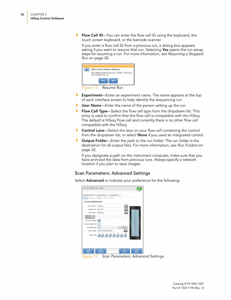
Flow Cell ID—You can enter the flow cell ID using the keyboard, the
touch screen keyboard, or the barcode scanner.
If you enter a flow cell ID from a previous run, a dialog box appears asking if you want to resume that run. Selecting Yes opens the run setup steps for resuming a run. For more information, see Resuming a Stopped Run on page 30.
Figure 11 Resume Run
Experiment—Enter an experiment name. The name appears at the top
of each interface screen to help identify the sequencing run.
User Name—Enter the name of the person setting up the run.
Flow Cell Type—Select the flow cell type from the dropdown list. This
entry is used to confirm that the flow cell is compatible with the HiSeq.
The default is HiSeq Flow cell and currently there is no other flow cell
compatible with the HiSeq.
Control Lane—Select the lane on your flow cell containing the control
from the dropdown list, or select None if you used an integrated control.
Output Folder—Enter the path to the run folder. The run folder is the
destination for all output files. For more information, see Run Folders on
page 32.
If you designate a path on the instrument computer, make sure that you have archived the data from previous runs. Always specify a network location if you plan to save images.
Scan Parameters: Advanced Settings
Select Advanced to indicate your preference for the following:
.
Figure 12 Scan Parameters, Advanced Settings

HiSeq Software Interface 19
HiSeq 2000 User Guide
Confirm First Base—Select the checkbox to receive a first base
confirmation dialog box that provides the option to abort the run at this
point or to continue.
If you do not select the checkbox, the first base report is generated as usual and the run continues without showing the first base report confirmation dialog box. The first base report may be accessed at any time during the run from the run folder. For more information, see First Base Report Confirmation on page 27.
Keep Intensity Files—Select the checkbox to save cluster intensity files
(*.cif) for later reanalysis, troubleshooting, or custom processing. Saving
intensity files is not required for on-instrument analysis.
Existing Recipe—If you wish to use an existing or custom recipe, enter
the path and recipe name. Illumina recommends using the recipe wizard
on the recipe parameters screen. For more information, see Recipe Parameters on page 19.
Save Images—By default, the software does not save images, and saved
images are not required for on-instrument analysis. If you choose to save
image samples, select one of the following options from the dropdown
list:
• Save Thumbnail Only—Thumbnail images are a combination of nine
images from each swath, combined in one thumbnail image. The
nine images are from the left, center, and right sections of the top,
center, and bottom regions of the swath. Thumbnail images are not
used for image analysis, but can be used to troubleshoot a run.
• Save Full Size Images—Saved image full size images may be used
for later reanalysis. However, saving images can increase processing
time. Always specify a network location for your run folder if you save
full size images.
Align Lanes—By default, all lanes are selected for alignment by RTA.
Deselect the checkbox for any lanes that do not have PhiX added to the
sample, so that RTA does not align and calculate error rates for that lane,
resulting in arbitrarily high error rates.
When you have entered the information for your run, select Next to move to the recipe parameters screen.
Recipe Parameters
The recipe parameters screen creates the recipe used for your run based on the information you entered. A copy of the recipe is automatically copied to the Recipe subfolder in the run folder for your run.
NOTEIllumina strongly recommends that you do not save full size images due to a significant negative effect on run performance, network performance, and archiving costs.
NOTEImage size per channel is about 650 MB. For example, full size images for 202 cycles, all four channels for every lane, and both surfaces of the flow cell require >16.4 TB of space.

20 CHAPTER 2
HiSeq Control Software
Catalog # SY-940-1001
Part # 15011190 Rev. D
Figure 13 Recipe Parameters
Indicate the number of cycles you plan to sequence on the recipe parameters screen:
Cycles—Enter the number of cycles you plan to sequence for Read 1,
and if applicable, the Index Read and Read 2. Entering a cycle count in
the Indexing or Read 2 field, adds additional fields to specify the
chemistry for each portion of the recipe.
SBS—Select the chemistry to use for your run from the dropdown list.
Index—Select the chemistry to use for the Index Read, if applicable.
PE Turnaround—Select the chemistry to use for the paired-end
turnaround (cluster resynthesis) step, if applicable.
When you have entered the information for your run, select Next to proceed to the reagent parameters screen.
Reagent Parameters
The reagent parameters screen records the following information about the reagents used for your run:
Figure 14 Reagent Parameters

HiSeq Software Interface 21
HiSeq 2000 User Guide
SBS Reagent Kit ID—Enter the SBS reagent kit ID using the keyboard,
the touch screen keyboard, or the barcode scanner. The reagent kit ID is
located on the reagent kit box.
Indexing Reagent Kit ID—For multiplexed sequencing runs, enter the
indexing reagent kit ID using the keyboard, the touch screen keyboard,
or the barcode scanner.
PE Reagent Kit ID—For paired-end sequencing runs, enter the paired-
end reagent kit ID using the keyboard, the touch screen keyboard, or the
barcode scanner.
New SBS Kit—This feature is not supported at this time. Instead, use
SBS Cycles Remaining.
SBS Cycles Remaining—Enter 101 cycles or less. The software counts
down the number of cycles entered prompts you to load fresh reagents
as needed. For more information, see Changing Reagents During a Run
on page 73.
Prime SBS Reagents—Select this checkbox to prime reagents before
you start a run, and select the appropriate priming recipe from the
dropdown list. Always prime reagents before loading a new flow cell.
Select Next to proceed. If you specified a number of cycles in the Indexing field on the recipe parameters screen, the indexing parameter screen opens. Otherwise, the review run setup screen opens.
Indexing Parameters
The indexing parameters screen provides a place to record the sample sheet associated with your multiplexed sequencing run. Enter or browse to the path and file name of the sample sheet for your run.
Figure 15 Indexing Parameters
Select Next to proceed to the review run setup screen.

22 CHAPTER 2
HiSeq Control Software
Catalog # SY-940-1001
Part # 15011190 Rev. D
Review Run Setup
The review run setup screen lists the information you entered for your run. If it is correct, select Next to proceed to the pre-run setup screens. Select Back if you need to change any entries.
Figure 16 Review Run Setup
Pre-Run Setup Screens
The pre-run setup screens guide you through loading reagents, loading a used flow cell for priming, performing a fluidics check, and priming reagents.
Load Reagents
The load reagents screen prompts you to load sequencing reagents provided in the HiSeq Sequencing Kit. If you plan to perform a multiplexed run, load multiplexing reagents on the paired-end rack. For more information, see Loading Sequencing Reagents on page 47.
The software pauses the run after Read 1 of a paired-end run, so that you can load the appropriate Read 2 reagents.
Figure 17 Load Reagents
After the appropriate reagents are loaded, select Next.
HiSeq Software Interface 23
HiSeq 2000 User Guide
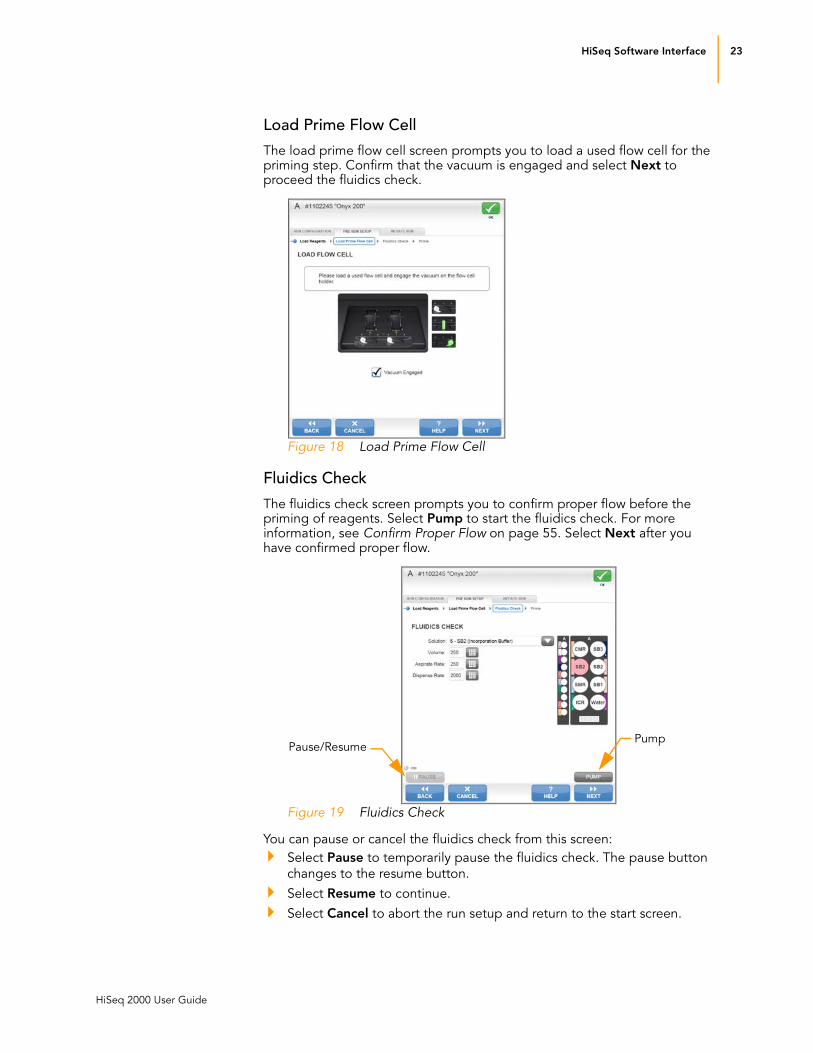
Load Prime Flow Cell
The load prime flow cell screen prompts you to load a used flow cell for the priming step. Confirm that the vacuum is engaged and select Next to proceed the fluidics check.
Figure 18 Load Prime Flow Cell
Fluidics Check
The fluidics check screen prompts you to confirm proper flow before the priming of reagents. Select Pump to start the fluidics check. For more information, see Confirm Proper Flow on page 55. Select Next after you have confirmed proper flow.
Figure 19 Fluidics Check
You can pause or cancel the fluidics check from this screen:
Select Pause to temporarily pause the fluidics check. The pause button
changes to the resume button.
Select Resume to continue.
Select Cancel to abort the run setup and return to the start screen.
Pause/ResumePump

24 CHAPTER 2
HiSeq Control Software
Catalog # SY-940-1001
Part # 15011190 Rev. D
Prime Reagents
From the prime screen, you can monitor the priming step in progress. If you need to pause or cancel the priming step, select Pause or Cancel.
Figure 20 Prime Reagents
You can pause or cancel the priming step from this screen:
Select Pause to temporarily pause the priming step. The pause button
changes to the resume button.
Select Resume to continue.
Select Cancel to abort the run setup and return to the start screen.
When priming of reagents is complete, the initiate run screens open.
Initiate Run Screens
The initiate run screens guide you through loading the new clustered flow cell, performing a fluidics check, and starting the run.
Load Sequencing Flow Cell
The load sequencing flow cell screen illustrates the steps to load the flow cell and engage the vacuum. For more information, see Loading a Clustered Flow Cell on page 58. Select Next to proceed.
Figure 21 Load Sequencing Flow Cell
Pause/Resume

HiSeq Software Interface 25
HiSeq 2000 User Guide
Fluidics Check
Always confirm proper flow prior to a sequencing run. Select the reagent you want to prime, volume, aspiration rate, and dispense rate. Select Pump to start the fluidics check. For more information, see Confirm Proper Flow on page 63. Select Next after you have confirmed proper flow.
Figure 22 Fluidics Check
Close Flow Cell Compartment Door
At this point, the software prompts you to close the flow cell compartment door. The software selects the Vacuum Engaged and Door Closed checkboxes when the system is ready. Select Next to proceed.
Figure 23 Close Flow Cell Compartment
Start Sequencing
The start sequencing screen is the last screen that appears before starting the run. Once the run begins you cannot change any of the run parameters without stopping the run. Select Start to begin the sequencing run.
26 CHAPTER 2
HiSeq Control Software
Catalog # SY-940-1001
Part # 15011190 Rev. D
Sequencing Screens
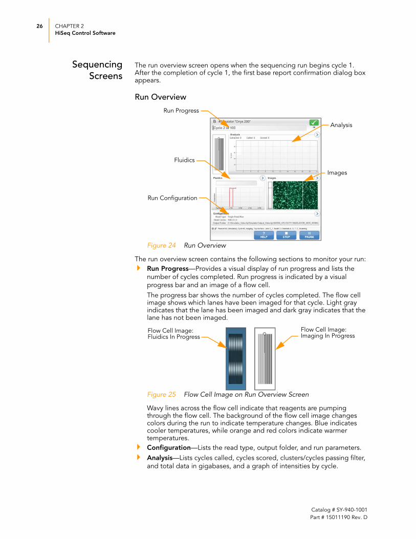
The run overview screen opens when the sequencing run begins cycle 1. After the completion of cycle 1, the first base report confirmation dialog box appears.
Run Overview
Figure 24 Run Overview
The run overview screen contains the following sections to monitor your run:
Run Progress—Provides a visual display of run progress and lists the
number of cycles completed. Run progress is indicated by a visual
progress bar and an image of a flow cell.
The progress bar shows the number of cycles completed. The flow cell image shows which lanes have been imaged for that cycle. Light gray indicates that the lane has been imaged and dark gray indicates that the lane has not been imaged.
Figure 25 Flow Cell Image on Run Overview Screen
Wavy lines across the flow cell indicate that reagents are pumping through the flow cell. The background of the flow cell image changes colors during the run to indicate temperature changes. Blue indicates cooler temperatures, while orange and red colors indicate warmer temperatures.
Configuration—Lists the read type, output folder, and run parameters.
Analysis—Lists cycles called, cycles scored, clusters/cycles passing filter,
and total data in gigabases, and a graph of intensities by cycle.
Run Configuration
Analysis
Run Progress
Images
Fluidics
Flow Cell Image: Imaging In Progress
Flow Cell Image: Fluidics In Progress

HiSeq Software Interface 27
HiSeq 2000 User Guide
HCS performs image analysis during the run. The software uses the first four cycles to initialize image analysis. By cycle five, image analysis results appear on the run overview screen.
Fluidics—Shows the current temperature, protocol step, and reagent.
The green line shows the temperature for the flow cell, the blue line shows the chiller temperature.
Images—Shows a sampling of three images from each swath. A swath is
the area imaged during one scanning pass of the flow cell. There are two
swaths per surface, resulting in four swaths for each lane. The three
images are samples from the current scan position.
Select the arrow button to expand any section on the run overview screen. For more information, see Monitoring the Run on page 65.
First Base Report Confirmation
The first base report confirmation dialog box appears automatically after the completion of cycle 1, if you selected the First Base Confirmation checkbox on the scan parameters screen. For more information, see Scan Parameters: Advanced Settings on page 18.
Figure 26 First Base Report
If the first base report is satisfactory, select Continue to begin your run. From this point the run is underway. You can walk away or monitor the run using the run overview screen.

28 CHAPTER 2
HiSeq Control Software
Catalog # SY-940-1001
Part # 15011190 Rev. D
Pausing, Stopping, and Resuming a Run
At any time during the run you can pause or stop the run. You might pause a run to check run components, such as reagent volumes, before proceeding with the run. You should only stop a run if the data is bad, if the run was set up incorrectly, or if there is a hardware error.
You can resume a paused run or a run that was stopped safely using the normal stop option.
Pausing a Run 1. From the run overview screen, select Pause. The pause menu appears.
Figure 27 Pause Menu
2. Select Normal Pause.
3. Select Yes to confirm the pause command. The software completes the
current chemistry or imaging command and places the flow cell in a safe
state.
Figure 28 Confirm Pause Command
4. The pause button changes to the resume button. Select Resume when
you are ready to resume the run.
Normal Pause

Pausing, Stopping, and Resuming a Run 29
HiSeq 2000 User Guide
Stopping a Run 1. From the run overview screen, select Stop. The stop menu appears.
Figure 29 Stop the Run
2. Select one of the following stop options:
• Normal Stop—Stops the run only after the current chemistry or
imaging command is complete, and then places the flow cell in a
safe state. Using the normal stop option allosw you to resume the
run at a later time.
Figure 30 Confirm Normal Stop
• Immediate Stop—Stops the run without completing the current
operation and does not place the flow cell in safe state. You cannot
resume a run that was stopped using the immediate stop option.
Figure 31 Immediate Stop Warning
3. After the run is stopped, select Return to Start on the run overview
screen. The start screen opens.
Normal Stop
Immediate Stop

30 CHAPTER 2
HiSeq Control Software
Catalog # SY-940-1001
Part # 15011190 Rev. D
Resuming a Stopped Run
Use the following instructions to resume a run that was stopped using the normal stop option:
1. From the start screen, select Sequence.
2. On the scan parameters screen, enter the flow cell ID from the run you
want to resume.
Figure 32 Resume Run
3. Select Yes to confirm that this is the correct flow cell ID and associated
run to resume. The resume parameters screen opens.
Figure 33 Resume Parameters
4. Select the run folder from the dropdown list and enter where in the run
you want to resume.
5. Select Next. The parameters from the previous run appear on the screen.

Pausing, Stopping, and Resuming a Run 31
HiSeq 2000 User Guide
Figure 34 Parameters from Previous Run
6. Select Next. The software prompts you to close the flow cell
compartment door.
7. Ensure the flow cell lever is green and close the flow cell compartment
door.
8. Ensure that the Vacuum Engaged and Door Closed checkboxes are
selected and select Next.
Figure 35 Close Flow Cell Compartment Door
9. Select Start to start the sequencing run.

32 CHAPTER 2
HiSeq Control Software
Catalog # SY-940-1001
Part # 15011190 Rev. D
Run Folders
Each run on the HiSeq generates a run folder that contains data files and log files for that run.
During run setup, the software prompts you to enter the path and folder name for the run folder. By default, the folder is named in the following format:
YYMMDD_<Workstation Name>_<Run Number>
Example: 090120_WORKSTATION-487_0002
The run number increments by one each time you perform a run on a given workstation. Typically, users add the flow cell ID to the run folder name. Do not include any spaces in the run folder name.
Run Folder Path All run folders are stored in a single folder. The location of the run folder is Illumina\HiSeqTemp. The flow cell ID entered during the run setup steps appends to the the end of the run folder name.
Contents of Run Folders
The following tables list the contents of the run folder and subfolders.
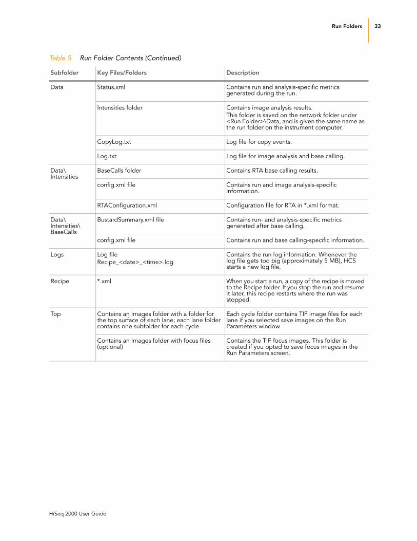
Table 5 Run Folder Contents
Subfolder Key Files/Folders Description
[Root level] First_Base_Report.txt File with basic metrics for the first cycle.
IALog.txt Log file for image analysis events.
Sample Sheet (optional) If you create a sample sheet, it is copied to this location, and the name is added to the params file in this folder. A sample sheet is required only if you do a multiplexing run.
RunInfo.xml Identifies high-level run information.
runParameters.xml Provides the setup parameters for the run.
Bottom Contains an Images folder with a folder for the bottom surface of each lane; each lane folder contains one subfolder for each cycle (optional)
Each cycle folder contains TIF image files for each lane if you selected save images on the Run Parameters window
Contains an Images folder with focus files Contains the TIF focus images.
Config Contains a copy of the software configuration parameters used for the run.
Run Folders 33
HiSeq 2000 User Guide
Data Status.xml Contains run and analysis-specific metrics generated during the run.
Intensities folder Contains image analysis results.
This folder is saved on the network folder under <Run Folder>\Data, and is given the same name as the run folder on the instrument computer.
CopyLog.txt Log file for copy events.
Log.txt Log file for image analysis and base calling.
Data\ Intensities
BaseCalls folder Contains RTA base calling results.
config.xml file Contains run and image analysis-specific information.
RTAConfiguration.xml Configuration file for RTA in *.xml format.
Data\ Intensities\ BaseCalls
BustardSummary.xml file Contains run- and analysis-specific metrics generated after base calling.
config.xml file Contains run and base calling-specific information.
Logs Log file
Recipe_<date>_<time>.log
Contains the run log information. Whenever the log file gets too big (approximately 5 MB), HCS starts a new log file.
Recipe *.xml When you start a run, a copy of the recipe is moved to the Recipe folder. If you stop the run and resume it later, this recipe restarts where the run was stopped.
Top Contains an Images folder with a folder for the top surface of each lane; each lane folder contains one subfolder for each cycle
Each cycle folder contains TIF image files for each lane if you selected save images on the Run Parameters window
Contains an Images folder with focus files (optional)
Contains the TIF focus images. This folder is created if you opted to save focus images in the Run Parameters screen.
Table 5 Run Folder Contents (Continued)
Subfolder Key Files/Folders Description
34 CHAPTER 2
HiSeq Control Software
Catalog # SY-940-1001
Part # 15011190 Rev. D
Available Disk Space
During the run at the end of each lane, the software checks available disk space. If disk space drops below the safe threshold, the software pauses the run and a message alerts you.
If you get this message, you need to make disk space available to continue the run. When sufficient disk space becomes available, the run automatically resumes.
The HiSeq instrument computer has a storage capacity of 1.8 TB per flow cell, enough space to hold a 209 cycle run if images are not saved to disk. Data from flow cell A is stored on the D: drive, while data from flow cell B is stored on the E: drive.

HiSeq 2000 User Guide 35
Chapter 3
Performing a Sequencing Run
Topics36 Introduction
37 Sequencing Workflow
38 Starting the HiSeq
39 Preparing Sequencing Reagents
41 Allocating Reagents For Shorter Runs
43 Preparing Multiplexing Reagents
44 Setting Up the Sequencing Run
47 Loading Sequencing Reagents
50 Loading Multiplexing Reagents
52 Loading a Used Flow Cell
57 Priming Reagents
58 Loading a Clustered Flow Cell
65 Monitoring the Run
73 Changing Reagents During a Run
70 Preparing ICR for Read 2
71 Preparing Paired-End Reagents
75 Loading ICR for Read 2
77 Loading Paired-End Reagents

36 CHAPTER 3
Performing a Sequencing Run
Catalog # SY-940-1001
Part # 15011190 Rev. D
Introduction
The section explains how to perform a sequencing run on the HiSeq.
The run is set up using the HCS software interface. The hands on time includes entering run information, loading and priming reagents, loading the new clustered flow cell, and performing a fluidics check. The sequencing run can be monitored from the run overview screen.
Multiplexed runs require additional reagents used for the Index Read, which are loaded onto the instrument at the beginning of the run. See Preparing Multiplexing Reagents on page 43.
Paired-end runs require additional reagents for Read 2 resynthesis, which are loaded onto the instrument after Read 1 is complete. See Preparing Sequencing Reagents on page 39.

Sequencing Workflow 37
HiSeq 2000 User Guide
Sequencing Workflow
The following diagram illustrates the HiSeq sequencing workflow for a multiplexed paired-end run. Steps specific to a multiplexed run and a paired-end run are labeled. All other steps are standard for any type of run.
Figure 36 Sequencing Workflow
Paired-End Runs
Prepare Reagents for Read 2 Resynthesis
Load Reagents for Read 2 Resynthesis
Prepare and Load ICR for Read 2
Read 2 Resynthesis
Monitor Read 2
Perform an Instrument Wash
Load Sequencing Reagents
Load Multiplexing Reagents
Load a Used Flow Cell
Confirm Proper Flow
Prime Sequencing Reagents
Measure Priming Waste
Prepare Sequencing Reagents
Prepare Multiplexing Reagents
Enter Run Parameters Using HCS Interface
Load a Clustered Flow Cell
Confirm Proper Flow
Inspect First Base Report After Cycle 1
Monitor Read 1
Prime Multiplexing Reagents
Index Read Preparation
Monitor the Index Read
Multiplexed Runs

38 CHAPTER 3
Performing a Sequencing Run
Catalog # SY-940-1001
Part # 15011190 Rev. D
Starting the HiSeq
It is best to leave the HiSeq on at all times. Turn the instrument off only if it will remain idle for more than three days.
Use the following instructions to start the HiSeq and instrument computer.
1. Start the HiSeq instrument control computer (Dell T7500).
2. Log on to the operating system using the default user name and
password. Wait until it has completely loaded.
• User name: sbsuser
• Password: sbs123
If the default values do not work, consult your IT personnel for the user name and password for your site.
3. Turn the HiSeq main power switch, located on the left side of the
instrument, to the ON position.
4. Wait for instrument drive called “DoNotEject” to initialize. A window
appears when the drive is initialized. Close the window.
5. To ensure adequate disk space, archive the data on the instrument
computer from all previous runs to a network location.
6. Open the HiSeq Control Software (HCS) using the icon on the computer
desktop. The HiSeq Control Software takes a few minutes to initialize.
When the software is initialized, the start screen appears.
7. Check for the initialization icon on the bottom left of the HCS
start screen to confirm complete instrument initialization.
NOTE
If you need to turn the instrument off, wait a minimum of 60 seconds before turning the main switch back to the ON position. This allows the electronics to discharge and ensures that the instrument initializes properly upon restart.
NOTE
Never eject the HiSeq “DoNotEject” flash drive located inside the HiSeq chassis, or modify the files on it. This drive contains hardware configuration files and initializes whenever the HiSeq is turned on.
NOTEThe HiSeq instrument computer has a storage capacity of 1.8 TB for each flow cell, enough space to hold a 209 cycle run if images are not saved to disk.

Preparing Sequencing Reagents 39
HiSeq 2000 User Guide
Preparing Sequencing Reagents
The HiSeq Sequencing Kit (200 Cycles) contains reagents sufficient for 209 cycles of sequencing. If you are performing a shorter run, see Allocating Reagents For Shorter Runs on page 41 for more information.
Reagent preparation requires the following three steps:
Thawing—CMR, SMR, and LFN require thawing prior to use. LRP does
not freeze and can remain in -15° to -25°C storage. ICR, SB1, SB2, and
SB3 are used directly from 2° to 8°C storage.
Allocating ICR for Read 1 and Read 2—You must split the volume of
ICR into two equal portions, one bottle for Read 1 and the other bottle
for Read 2. You can prepare and use both bottles immediately for
concurrent runs, or you can use one bottle now and store the other
bottle for Read 2 of the same run.
Preparing ICR—ICR is the only reagent that requires mixing prior to use.
Thaw Reagents Sequencing reagents CMR-200 cycles, SMR-200 cycles, and LFN36 require thawing prior to your sequencing run. Start the thawing process about 17 hours prior to your run.
1. Leave LRP-200 cycles in -15° to -25°C storage until you are ready to use
it to prepare ICR.
2. Remove SMR-200 cycles and CMR-200 cycles from -15° to -25°C storage
and thaw at 2° to 8°C overnight (at least 16 hours).
3. After overnight thawing, place the reagent bottles in a rack, and then
place the rack in a water bath filled with room temperature deionized
water for about one hour to finish thawing.
4. Invert each bottle several times and inspect the reagents for ice crystals.
Ensure the reagents are completely thawed.
5. Remove LFN36 from -15° to -25°C storage and thaw in a beaker
containing room temperature deionized water for 20 minutes.
Only thaw two tubes of LFN36 if you plan to use half of the ICR at this time, such as for Read 1. Thaw all four tubes of LFN36 if you plan to use both halves of ICR now, such as for two concurrent runs.
6. When thawed, set SMR-200 cycles, CMR-200 cycles, and LFN36 aside on
ice until you are ready to load them onto the instrument.
7. Use ICR-200 cycles, SB1-200 cycles, SB2-200 cycles, and SB3-200 cycles
directly from 2° to 8°C storage.
8. Record the lot numbers of each reagent on the lab tracking form.
Allocate ICR 1. Aliquot 47 ml of ICR-200 cycles into a spare 250 ml bottle to result in two
equal volumes of ICR.
2. Do one of following:

40 CHAPTER 3
Performing a Sequencing Run
Catalog # SY-940-1001
Part # 15011190 Rev. D
• Two Flow Cells—If you are preparing reagents to run two flow cells
concurrently, prepare both bottles of ICR as described in Prepare ICR for 108 Cycles. Use a new Sequencing Kit for Read 2 of a paired-end
run, and repeat the thawing and allocating procedure.
• One Flow Cell—If you are preparing reagents to run one flow cell at
this time, prepare only one bottle of ICR as described in Prepare ICR for 108 Cycles. Return the second bottle of ICR to 2° to 8°C storage
until you are ready to load reagents for Read 2.
Prepare ICR for 108 Cycles
1. Add the contents of two tubes of LFN36 to the bottle containing 47 ml of
ICR-200 cycles.
2. Rinse each tube of LFN36 with ICR-200 cycles to ensure that all LFN36 is
transferred.
3. Aliquot 1.1 ml of LRP-200 cycles into the ICR/LFN36 mix.
4. Return the unused portion of LRP-200 cycles to -15° to -25°C storage.
5. Cap the bottle and invert several times to mix.
6. Set aside on ice until you are ready to load reagents onto the HiSeq.
NOTEIllumina recommends preparing and using the “spare” bottle of ICR first and storing the labeled bottle of ICR as the original label contains important expiry information.
Allocating Reagents For Shorter Runs 41
HiSeq 2000 User Guide
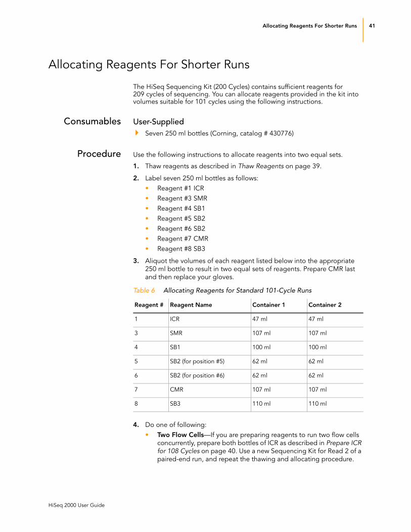
Allocating Reagents For Shorter Runs
The HiSeq Sequencing Kit (200 Cycles) contains sufficient reagents for 209 cycles of sequencing. You can allocate reagents provided in the kit into volumes suitable for 101 cycles using the following instructions.
Consumables User-SuppliedSeven 250 ml bottles (Corning, catalog # 430776)
Procedure Use the following instructions to allocate reagents into two equal sets.
1. Thaw reagents as described in Thaw Reagents on page 39.
2. Label seven 250 ml bottles as follows:
• Reagent #1 ICR
• Reagent #3 SMR
• Reagent #4 SB1
• Reagent #5 SB2
• Reagent #6 SB2
• Reagent #7 CMR
• Reagent #8 SB3
3. Aliquot the volumes of each reagent listed below into the appropriate
250 ml bottle to result in two equal sets of reagents. Prepare CMR last
and then replace your gloves.
4. Do one of following:
• Two Flow Cells—If you are preparing reagents to run two flow cells
concurrently, prepare both bottles of ICR as described in Prepare ICR for 108 Cycles on page 40. Use a new Sequencing Kit for Read 2 of a
paired-end run, and repeat the thawing and allocating procedure.
Table 6 Allocating Reagents for Standard 101-Cycle Runs
Reagent # Reagent Name Container 1 Container 2
1 ICR 47 ml 47 ml
3 SMR 107 ml 107 ml
4 SB1 100 ml 100 ml
5 SB2 (for position #5) 62 ml 62 ml
6 SB2 (for position #6) 62 ml 62 ml
7 CMR 107 ml 107 ml
8 SB3 110 ml 110 ml

42 CHAPTER 3
Performing a Sequencing Run
Catalog # SY-940-1001
Part # 15011190 Rev. D
• One Flow Cell—If you are preparing reagents to run one flow cell at
this time, prepare only one bottle of ICR as described in Prepare ICR for 108 Cycles on page 40. Return the second set of reagents to
proper storage. Store CMR, SMR, and LRP at -15° to -25°C. Store
ICR, SB1, SB2, and SB3 at 2° to 8°C.

Preparing Multiplexing Reagents 43
HiSeq 2000 User Guide
Preparing Multiplexing Reagents
The following reagents are used for Index Read preparation prior to the start of the Index Read. They are provided in the Multiplexing Sequencing Primers and PhiX Control Kit. For more information, see Multiplexing Sequencing Reagents on page 12.
Thaw Reagents 1. Remove the following multiplexing reagents from -15° to -25°C storage:
• 2.0 N NaOH
• Wash Buffer
• Hybridization Buffer
• Index Seq Primer
Do not thaw the Multiplexing Rd2 Seq Primer at this time.
2. Thaw at room temperature or in a beaker containing room temperature
deionized water.
Prepare Reagents
Prepare 0.1 N NaOH
Dilute 2 N NaOH to 0.1 N NaOH prior to loading it onto the HiSeq.
1. Invert the container of 2 N NaOH five times to mix the reagent, and then
pulse centrifuge the reagent.
2. Transfer 3,325 μl of PW1 (provided in the Sequencing Kit) into a 15 ml
conical tube, and add 175 μl of 2 N NaOH.
3. Invert the tube five times to mix the reagent.
4. Label the conical tube of 0.1 N NaOH “Reagent #18.”
5. Centrifuge at 1,000 rpm for one minute.
6. Set aside at room temperature until you are ready to load reagents onto
the HiSeq.
Prepare Wash Buffer
1. Invert the container of Wash Buffer five times to mix the reagent, and
then transfer 4 ml of Wash Buffer into a 15 ml conical tube.
2. Label the tube “Reagent #19.”
3. Set aside at room temperature until you are ready to load reagents onto
the HiSeq.
Prepare Index Seq Primer
1. Transfer 2,985 μl of Hybridization Buffer into a 15 ml conical tube, and
add 15 μl of Index Seq Primer.
2. Vortex the tube to mix the reagent.
3. Label the tube “Reagent #17.”
4. Set aside at room temperature until you are ready to load reagents onto
the HiSeq.

44 CHAPTER 3
Performing a Sequencing Run
Catalog # SY-940-1001
Part # 15011190 Rev. D
Setting Up the Sequencing Run
The HiSeq software interface guides you through the run setup steps. For more information, see HiSeq Software Interface on page 15.
Prerequisites You have recently performed an instrument wash. For more information,
see Performing a Maintenance Wash on page 84.
You have thawed and prepared sequencing reagents. For more
information, see Preparing Sequencing Reagents on page 39.
Procedure 1. From the start screen, select Sequence. The scan parameters screen
opens.
Figure 37 Enter Scan Parameters
2. Enter the following parameters for your run:
a. Scan or enter the flow cell ID of the flow cell to be sequenced.
b. Enter your experiment name and user name.
c. Select the flow cell type from the dropdown list.
d. Select the lane containing the control, if applicable. If you used an
integrated control, select None.
e. Enter or browse to the path of your run folder and enter the run
folder name.
f. If applicable, select the notifications checkbox to receive email
messages about the status of your run.
3. Select Advanced to expand the following additional settings:
a. Select the Confirm First Base checkbox to generate a first base
report confirmation.
b. Select the Save Images checkbox to save thumbnail images. For
more information, see Scan Parameters: Advanced Settings on
page 18.
c. Select the Use Existing Recipe checkbox only if you want to use a
custom recipe. Otherwise, allow the software to create your recipe
based on information you provide on the run setup screens.
4. Select Next. The recipe parameters screen opens.

Setting Up the Sequencing Run 45
HiSeq 2000 User Guide
Figure 38 Enter Recipe Parameters
5. Enter the following recipe parameters:
a. Enter the number of cycles you plan to sequence for Read 1, and if
applicable, the Index Read and Read 2.
b. Select the appropriate SBS chemistry from the dropdown list.
c. If you are performing a multiplexed run, select the appropriate Index
chemistry from the dropdown list.
d. If you are performing a paired-end run, select the appropriate PE
turnaround chemistry from the dropdown list.
6. Select Next. The reagent parameters screen opens.
Figure 39 Enter Reagent Parameters
7. Enter the following reagent parameters:
a. Scan or enter the reagent kit IDs for the kits you are using to perform
your run. Reagent kit IDs are located on the reagent kit box.
b. Select the reagent kit type from the dropdown list.
c. Specify 101 cycles or less. The software prompts you to load fresh
ICR and paired-end reagents after the last cycle of Read 1
completes.

46 CHAPTER 3
Performing a Sequencing Run
Catalog # SY-940-1001
Part # 15011190 Rev. D
8. Select Next. The indexing parameters screen opens if you entered a
number greater than zero for the index read. Otherwise, the review run
setup screen opens.
Figure 40 Enter Indexing Parameters
9. Browse to the path and file name of the sample sheet for your
multiplexed sequencing run.
10. Select Next. The review run setup screen opens.
11. Review your run information. If it is correct, select Next and proceed to
Loading Sequencing Reagents on page 47. Select Back if you need to
change any entries.

Loading Sequencing Reagents 47
HiSeq 2000 User Guide
Loading Sequencing Reagents
The next step in the run setup is to load sequencing reagents followed by the priming step. The software interface guides you through the process.
Consumables Illumina-SuppliedThoroughly thawed and prepared sequencing reagents
(Provided in the HiSeq Sequencing Kit)
Seven funnel caps
(Provided in the HiSeq Cluster Generation Kit)
User-SuppliedOne 250 ml bottle (Corning, catalog # 430776) containing 5 ml of
laboratory grade water
Procedure 1. Record the weight of each reagent on the lab tracking form.
2. Open the reagent compartment door.
Figure 41 Reagent Racks
3. Raise the sippers for the reagent rack you are loading using the following
motion:
a. Pull the sipper handle towards you.
b. Push the sipper handle up while pulling it towards you.
NOTEWeighing reagents before and after a sequencing run confirms proper reagent delivery.
Reagent Rack for
Paired-End Reagents
Reagent Rack for Flow Cell BReagent Rack for Flow Cell A
Sipper Handles

48 CHAPTER 3
Performing a Sequencing Run
Catalog # SY-940-1001
Part # 15011190 Rev. D
c. Release the sipper handle into the slot on top end of the groove. You
should feel the sipper handle rest securely into the slot.
4. Slide the reagent rack out of the reagent compartment using the rack
handle.
5. Place each reagent bottle onto the rack in the associated numbered
position, making sure that the conical end of the bottle rests in the
indentation on the base of the rack.
Figure 42 Sequencing Reagent Rack (A or B)
NOTE
The paired-end rack is located to the left of Rack A and holds two sets of paired-end reagents used during the resynthesis step of a paired-end run. For more information, see Loading Paired-End Reagents on page 77.
Table 7 Sequencing Reagent Positions (Rack A or B)
Position Reagent Description
1 ICR Incorporation Mix Reagent
2 Water 250 ml bottle with laboratory-grade water
3 SMR Scanning Mix Reagent
4 SBS Buffer 1 (SB1) High Salt Buffer
5 SBS Buffer 2 (SB2) Incorporation Buffer
6 SBS Buffer 2 (SB2) Incorporation Buffer
7 CMR Cleavage Mix Reagent
8 SBS Buffer 3 (SB3) Cleavage Buffer
7CMR
5SB2
3SMR
1ICR
8SB3
6SB2
4SB1
2Water

Loading Sequencing Reagents 49
HiSeq 2000 User Guide
6. Remove the cap from each bottle of ICR, SMR, SB1, SB2, and SB3, and
replace it with a funnel cap. Funnel caps are provided in the HiSeq
Accessories Kit, part of the HiSeq Cluster Generation Kit.
7. Remove the cap from the CMR bottle and replace it with a funnel cap.
Replace your gloves.
8. Slide the reagent rack into the reagent compartment, aligning the rack
with the raised guide on the floor of the compartment.
9. Lower the sippers into the reagent bottles of the appropriate rack using
the following motion:
a. Pull the sipper handle towards you.
b. Lower the sipper handle while pulling it towards you.
c. Release the sipper handle into the slot on the bottom end of the
groove. You should feel the sipper handle rest securely into the slot.
10. Visually inspect the sippers to ensure they are centered inside the
bottles, and did not bend as they were lowered into the funnel caps.
11. For multiplexed runs, proceed to Loading Multiplexing Reagents on
page 50. Otherwise, go to the next step.
12. Close the reagent compartment door.
Figure 43 Load Reagents
13. Select Next and proceed to Loading a Used Flow Cell on page 52.
NOTEAlways use the funnel caps on reagent bottles. The small hole in the cap minimizes the risk of contamination.
CAUTIONAfter handling the bottle of CMR, be sure to discard your gloves and replace them with a new pair.

50 CHAPTER 3
Performing a Sequencing Run
Catalog # SY-940-1001
Part # 15011190 Rev. D
Loading Multiplexing Reagents
If you are performing a multiplexed run, you need to load multiplexing reagents onto the instrument before you start the run. The paired-end rack is located to the left of Rack A and holds two sets of multiplexing reagents, one set for each flow cell.
Figure 44 Paired-End/Multiplexing Reagent Rack
1. Record the weight of each reagent on the lab tracking form.
2. Raise the sippers for the paired-end reagent rack using the following
motion:
a. Pull the handle towards you.
b. Push the handle up while pulling it towards you.
c. Release the handle into the slot on top end of the groove. You
should feel the handle rest securely into the slot.
3. Slide the reagent rack out of the reagent compartment using the rack
handle.
4. Place each of the reagent tubes onto the rack in the associated
numbered positions.
NOTEIt is very important to ensure that reagents are thoroughly mixed before loading them onto the instrument.
Table 8 Multiplexing Reagent Positions
Position Reagent Description
17 ISP Indexing Seq Primer
18 HP3 0.1 N NaOH
19 HT2 Wash Buffer
Reagent Rack for Multiplexing Reagents
Sipper Handle

Loading Multiplexing Reagents 51
HiSeq 2000 User Guide
Figure 45 Paired-End Reagent Rack
5. Remove the caps from each reagent tube.
6. Slide the reagent rack into the reagent compartment, aligning the rack
with the raised guide on the floor of the compartment.
7. Lower the sippers into the paired-end reagent tubes using the following
motion:
a. Pull the handle towards you.
b. Lower the handle while pulling it towards you.
c. Release the handle into the slot on the bottom end of the groove.
You should feel the handle rest securely into the slot.
8. Visually inspect the sippers to ensure they are centered inside the tubes,
and did not bend as they were lowered into the tubes.
9. Close the reagent compartment door.
10. Select Next to proceed to loading a used flow cell.
10
AAA B
11
12
13
14
15
16
17
18
19
10
11
12
13
14
15
16
17
18
19 HT2 (Wash Buffer)
HP3 (Diluted to 0.1 N NaOH)
ISP (Indexing Seq Primer)

52 CHAPTER 3
Performing a Sequencing Run
Catalog # SY-940-1001
Part # 15011190 Rev. D
Loading a Used Flow Cell
The HiSeq must be loaded with a used flow cell before performing an instrument wash or priming reagents. If you do not have a used flow cell, contact your Illumina Field Application Scientist (FAS) or Field Service Engineer (FSE).
If you are ready to perform a post-run wash at the completion of your sequencing run, leave the flow cell on the instrument and proceed to Performing a Post-Run Instrument Wash on page 89.
Consumables User-SuppliedLens cleaning tissue
70% ethanol or alcohol wipes
Low-lint lab tissue
Used HiSeq flow cell
Clean the Flow Cell Holder
1. Open the flow cell compartment door.
2. Make sure that the flow cell lever for the flow cell you are loading, either
A or B, is in the OFF position (far-left).
Figure 46 Flow Cell Lever in OFF Position (Far-Left)
3. Put on a new pair of powder-free latex gloves.
4. Using an alcohol wipe or a lint-free tissue moistened with ethanol or
isopropanol, carefully wipe the surface of the flow cell holder until it is
completely clean.
WARNINGWARNINGDo not set fluids on the flow cell compartment door or on the flow cell stage when the door is open. Spills in this area can damage the instrument.
NOTEDo not allow alcohol to drip into the vacuum holes or around the manifolds. Use a low-lint lab tissue to dry the stage, if necessary.
Flow Cell Lever A Flow Cell Lever B

Loading a Used Flow Cell 53
HiSeq 2000 User Guide
5. Visually inspect the flow cell holder to make sure it is free of lint, and the
vacuum holes are free of obstructions.
Figure 47 Vacuum Hole Locations
Load Used Flow Cell
You are ready to load the used flow cell. You may reuse existing gaskets when loading a used flow cell for instrument washes or reagent priming.
1. Remove the used flow cell from storage buffer and clean it using alcohol
wipes and lens cleaning tissue.
2. Place the used flow cell on the flow cell holder with the inlet and outlet
ports facing down and the barcode on the right. The arrow on the left
edge of the flow cell, which indicates flow direction, should point
towards the instrument.
3. Gently slide the flow cell towards the top and right guide pins until it
stops.
Figure 48 Position Flow Cell Against Top and Right Guide Pins
Vacuum Holes
(Flow Cell A)
Vacuum Holes
(Flow Cell B)
NOTERemove your hand from the flow cell before engaging the vacuum switch. This prevents any pressure on the guide pins that may cause alignment drift over time.
Top Guide Pin Right Guide Pins

54 CHAPTER 3
Performing a Sequencing Run
Catalog # SY-940-1001
Part # 15011190 Rev. D
4. Move the flow cell lever slowly to position 1 (middle), until it is pointing
upward. This engages the vacuum and secures the flow cell into position.
The flow cell lever turns yellow, and then quickly blinks green. When the
flow cell lever is green, the vacuum is engaged. If the flow cell lever
remains yellow, the vacuum seal is not secure. Repeat the cleaning steps
and reload the flow cell.
Figure 49 Flow Cell Lever in Position 1 (Middle)
5. Wait for about five seconds, and then move the flow cell lever slowly to
position 2 (far-right). This raises the manifolds, allowing the gaskets to
make contact with the flow cell. When the flow cell lever is solid green,
the flow cell is ready for use.
If the flow cell lever remains yellow, the manifolds did not engage or the vacuum seal has been lost. Remove the flow cell, repeat the cleaning steps, and reload the flow cell.
Figure 50 Flow Cell Lever in Position 2 (Far-Right)
6. Ensure the Vacuum Engaged checkbox is selected on the load prime
flow cell screen.
Flow Cell A Vacuum Engaged

Loading a Used Flow Cell 55
HiSeq 2000 User Guide
Figure 51 Load Prime Flow Cell
7. Select Next to proceed to the fluidics check.
Confirm Proper Flow
After the used flow cell is loaded, you are ready to check for proper flow using the fluidics check screen. Checking for proper flow confirms that the flow cell and gaskets are properly installed and the manifold is engaged.
Figure 52 Fluidics Check
1. Select solution 5 (SB2) from the dropdown list.
2. Enter the following default values:
• Volume: 250
• Aspiration Rate: 250
• Dispense Rate: 2,000
3. Select Pump.
4. Visually inspect the flow cell for bubbles passing through the lanes and
leaks near the manifolds.
If you see excessive bubbles, check the gaskets for obstructions, reduce the aspiration rate to 100, and pump another 250 μl of water to the flow

56 CHAPTER 3
Performing a Sequencing Run
Catalog # SY-940-1001
Part # 15011190 Rev. D
cell. For more information, see Troubleshooting on page 106. If problems persist, contact Illumina Technical Support.
Prepare for Priming
1. Prepare the waste tubes for collection of priming waste as follows:
a. Loosen and remove the eight lines of waste tubing for the
appropriate flow cell from the waste container.
b. Place each waste tubing into an empty 15 ml tube, one line per tube.
Priming waste is collected and measured after the priming step.
2. Select Next. The priming screen opens and the priming step starts
automatically.
NOTEBe sure you do not include the eight lines for the opposite flow cell, the condensation pump, or the two paired-end priming pumps.

Priming Reagents 57
HiSeq 2000 User Guide
Priming Reagents
You are ready to prime reagents through the fluidics lines.
You can monitor the progress of the priming step from the priming screen.
Figure 53 Prime Reagents
1. When the priming step is complete, measure the collected priming waste
and confirm that the volume is 1.75 ml from each lane. Record the results
on the lab tracking form.
If the measured volume differs from the expected volume by more than 10%, repeat the priming step.
2. Return the waste tubing to the waste container before proceeding.
3. Select Next. You are ready to load the clustered flow cell. Proceed to
Loading a Clustered Flow Cell on page 58.

58 CHAPTER 3
Performing a Sequencing Run
Catalog # SY-940-1001
Part # 15011190 Rev. D
Loading a Clustered Flow Cell
After priming is complete, you are ready to load the clustered flow cell onto the HiSeq for sequencing.
Consumables User-SuppliedLens cleaning tissue
70% ethanol or alcohol wipes
Low-lint lab tissue
Remove the Used Flow Cell
1. Open the flow cell compartment door.
Figure 54 Flow Cell Lever in Position 1 (Middle)
2. Slowly move the flow cell lever to position 1 (middle) to disengage the
manifolds.
3. Slowly move the flow cell lever to the OFF position (far-left) to disengage
the vacuum seal and release the flow cell.
WARNINGWARNINGDo not set fluids on the flow cell compartment door or on the flow cell stage when the door is open. Spills in this area can damage the instrument.
Flow Cell A
Vacuum Engaged

Loading a Clustered Flow Cell 59
HiSeq 2000 User Guide
Figure 55 Flow Cell Lever in OFF Position (Far-Left)
4. Lift the used flow cell from the flow cell holder.
5. Remove the used gaskets and discard them.
Figure 56 Remove Used Manifold Gaskets
Clean the Flow Cell Holder
1. Put on a new pair of powder-free latex gloves.
2. Using an alcohol wipe or a lint-free tissue moistened with ethanol or
isopropanol, carefully wipe the surface of the flow cell holder until it is
completely clean.
Flow Cell Lever A in OFF Position
Manifold Gaskets
(Flow Cell A)
NOTEDo not allow alcohol to drip into the vacuum holes or around the manifolds. use a low-lint lab tissue to dry the stage, if necessary.
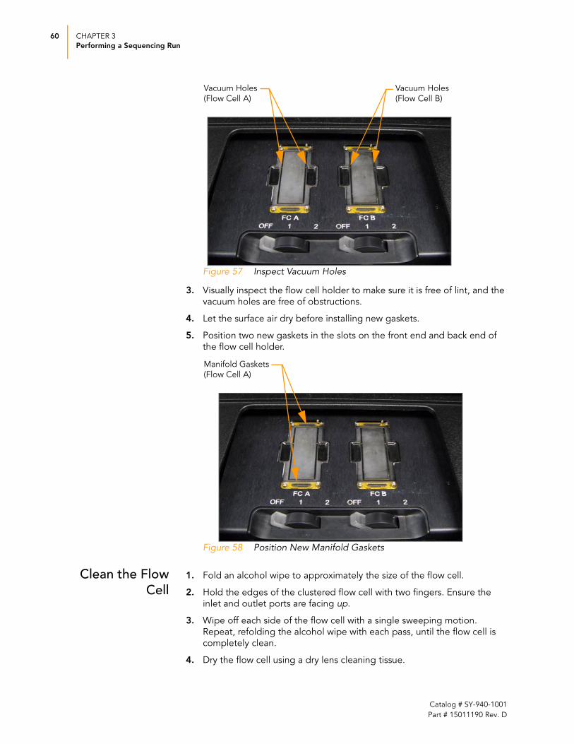
60 CHAPTER 3
Performing a Sequencing Run
Catalog # SY-940-1001
Part # 15011190 Rev. D
Figure 57 Inspect Vacuum Holes
3. Visually inspect the flow cell holder to make sure it is free of lint, and the
vacuum holes are free of obstructions.
4. Let the surface air dry before installing new gaskets.
5. Position two new gaskets in the slots on the front end and back end of
the flow cell holder.
Figure 58 Position New Manifold Gaskets
Clean the Flow Cell
1. Fold an alcohol wipe to approximately the size of the flow cell.
2. Hold the edges of the clustered flow cell with two fingers. Ensure the
inlet and outlet ports are facing up.
3. Wipe off each side of the flow cell with a single sweeping motion.
Repeat, refolding the alcohol wipe with each pass, until the flow cell is
completely clean.
4. Dry the flow cell using a dry lens cleaning tissue.
Vacuum Holes
(Flow Cell A)
Vacuum Holes
(Flow Cell B)
Manifold Gaskets
(Flow Cell A)

Loading a Clustered Flow Cell 61
HiSeq 2000 User Guide
5. Protect the flow cell from dust until you are ready to load it onto the
HiSeq.
Load the Clustered Flow
Cell
You are ready to load the clustered flow cell.
1. Place the flow cell on the flow cell holder with the inlet and outlet ports
facing down and the barcode on the right. The arrow on the left edge of
the flow cell, which indicates flow direction, should point towards the
instrument.
2. Gently slide the flow cell towards the top and right guide pins until it
stops.
Figure 59 Position Flow Cell Against Top and Right Guide Pins
3. Move the flow cell lever slowly to position 1 (middle), until it is pointing
upward. This engages the vacuum and secures the flow cell into position.
The flow cell lever turns yellow, and then quickly blinks green. When the
flow cell lever is green, the vacuum is engaged.
If the flow cell lever remains yellow, the vacuum seal is not secure. Remove the flow cell, and inspect the gaskets and vacuum holes. Repeat the cleaning steps, if necessary, and reload the flow cell.
CAUTION
If you clean the flow cell while it is lying on the bench top, you could easily apply too much pressure and break the flow cell. Illumina recommends cleaning the flow cell while holding the edges between your fingers.
NOTEAlways replace the manifold gaskets when loading a new clustered flow cell.
NOTERemove your hand from the flow cell before engaging the vacuum switch. This prevents any pressure on the guide pins that may cause alignment drift over time.
Top Guide Pin Right Guide Pins

62 CHAPTER 3
Performing a Sequencing Run
Catalog # SY-940-1001
Part # 15011190 Rev. D
Figure 60 Flow Cell Lever in Position 1 (Middle)
4. Wait for about five seconds, and then move the flow cell lever slowly to
position 2 (far right). This raises the manifolds, allowing the gaskets to
make contact with the flow cell. When the flow cell lever is solid green,
the flow cell is ready for use.
If the flow cell lever remains yellow, the manifolds did not engage or the vacuum seal has been lost. Remove the flow cell, repeat the cleaning steps, and reload the flow cell.
Figure 61 Flow Cell Lever in Position 2 (Far-Right)
5. Ensure the Vacuum Engaged checkbox is selected on the load
sequencing flow cell screen.
Flow Cell A Vacuum Engaged

Loading a Clustered Flow Cell 63
HiSeq 2000 User Guide
Figure 62 Load Sequencing Flow Cell
6. From the load sequencing flow cell screen, select Next to proceed to the
fluidics check.
Confirm Proper Flow
After the clustered flow cell is loaded, you are ready to check for proper flow using the fluidics check screen. Checking for proper flow confirms that the flow cell and gaskets are properly installed and the manifold is engaged.
Figure 63 Fluidics Check
1. Select solution 5 (SB2) from the dropdown list.
2. Enter the following default values:
• Volume: 250
• Aspiration Rate: 250
• Dispense Rate: 2,000
3. Select Pump.
4. Visually inspect the flow cell for bubbles passing through the lanes and
leaks near the manifolds.

64 CHAPTER 3
Performing a Sequencing Run
Catalog # SY-940-1001
Part # 15011190 Rev. D
If you see excessive bubbles, check the gaskets for obstructions, reduce the aspiration rate to 100, and pump another 250 μl of SB2 to the flow cell. For more information, see Troubleshooting on page 106. If problems persist, contact Illumina Technical Support.
5. After you have confirmed proper flow, select Next to proceed. The
software prompts you to close the flow cell compartment door.
6. Ensure the flow cell lever is green and close the flow cell compartment
door.Ensure that the Vacuum Engaged and Door Closed checkboxes
are selected and select Next.
Figure 64 Close Flow Cell Compartment Door
7. Select Start to start the sequencing run.
Figure 65 Start Sequencing Run

Monitoring the Run 65
HiSeq 2000 User Guide
Monitoring the Run
The run overview screen shows the progress of your run. Use this screen to monitor on-instrument analysis, fluidics, and imaging. For more information, see Run Overview on page 26.
If you are performing a paired-end sequencing run, be prepared to load paired-end reagents and fresh sequencing reagents prior to the start of Read 2 resynthesis. For more information, see Preparing ICR for Read 2 on page 70 and Preparing Paired-End Reagents on page 71.
Figure 66 Run Overview
1. Use the progress bar to monitor how many cycles are complete.
2. View the flow cell image to monitor which lanes have been imaged for
that cycle and to visualize fluidics flow and temperature changes.
3. Select the arrow button to expand the analysis section to monitor cluster
intensities, cluster density, and Qscores.
• Flow Cell Chart—Metrics displayed per tile on the flow cell image,
filtered by cycle and base (when appropriate). The color bar to the
right indicates the values that the colors represent.
— Intensity—Displays cluster intensity by base.
— FWHM—Displays the focus quality, as indicated by the full width
at half maximum of clusters (in pixels).
— % Base—Displays the bases read on the flow cell.
— % >Q20—Displays the percentage of bases with a quality score
of 20 or higher by cycle for each tile, generated after cycle 25.
— % >Q30—Displays the percentage of bases with a quality score
of 30 or higher by cycle for each tile, generated after cycle 25.
— Error rate—Displays the calculated error rate, as determined by a
spiked in PhiX control sample.
Run Configuration
Analysis
Run Progress
Images
Fluidics and Temperature
66 CHAPTER 3
Performing a Sequencing Run
Catalog # SY-940-1001
Part # 15011190 Rev. D
• Data By Cycle—Metrics displayed per cycle, filtered by lane, surface,
and base (when appropriate).
— Intensity—Displays cluster intensity by base.
— FWHM—Displays the focus score, as indicated by the full width
at half maximum of clusters (in pixels).
— % Base—Displays the bases read.
— % >Q20—Displays the percentage of bases with a quality score
of 20 or higher by cycle for each tile, generated after cycle 25.
— % >Q30—Displays the percentage of bases with a quality score
of 30 or higher by cycle for each tile, generated after cycle 25.
— Error rate—Displays the calculated error rate, as determined by a
spiked in PhiX control sample.
— % Perfect Reads—displays the percentage of perfect reads,
determined by a spiked in PhiX control sample.
• Data By Lane—Metrics displayed per cycle, filtered by surface and
read (when appropriate).
— Clusters—The density of clusters detected by image analysis,
and density of clusters passing filtering.
— % Phasing—The percentage of molecules in a cluster for which
sequencing falls behind (phasing) or jumps ahead (prephasing)
the current cycle within a read.
— % Prephasing—The percentage of molecules in a cluster for
which sequencing jumps ahead the current cycle within a read.
— % Aligned—The percentage of the sample that aligned to the
PhiX genome. Only informative if the lane contains a PhiX
control sample.
• Qscore Distribution—Histogram of quality scores across all cycles
and lanes. Filter data by cycle, lane, and surface.
• Qscore Heatmap—Heatmap of quality scores. Filter data by lane
and surface.
• Plot Features—The plots share the following features:
— The red line indicates the median tile value.
— The box outlines the interquartile range (the middle 50% of the
data) for the tiles analyzed for the data point.
— The error bars delineate the minimum and maximum without
outliers.
— The outliers are the values that are more than 1.5 times the
interquartile range below the 25th percentile, or more than 1.5
times the interquartile range above the 75th percentile. Outliers
are indicated as dots.
— The numbers above the X-axis indicate the number of analyzed
tiles used for the data point.

Monitoring the Run 67
HiSeq 2000 User Guide
Figure 67 Analysis Expanded
4. Select the arrow button to expand the fluidics section and monitor
individual steps in the protocol, temperature changes, and reagent
locations.
Figure 68 Fluidics Expanded
5. Select the arrow button to expand the images section and monitor
image samples and associated data.
NOTECycle 4 takes longer to process due to analysis template generation. This delay is normal.

68 CHAPTER 3
Performing a Sequencing Run
Catalog # SY-940-1001
Part # 15011190 Rev. D
Figure 69 Images Expanded
6. Access the status page generated by Real Time Analysis (RTA). The
status page provides access to analysis metrics in plots, graphs, and
tables. For more information, see Real Time Analysis on page 93.
Figure 70 Access the Status Page
Open Status Page

Monitoring the Run 69
HiSeq 2000 User Guide
First-Base Incorporation
The first base report confirmation dialog box appears automatically after cycle one is complete, if you selected the Confirm First Base checkbox on the scan parameters screen.
If you did not select the checkbox, the run continues after first base incorporation without prompting you to review the first base report. For more information, see Scan Parameters: Advanced Settings on page 18.
Figure 71 First Base Report
1. Review the first base report from the first base report confirmation dialog
box or by opening First_Base_Report.txt from the root level of the run
folder.
2. If the results are satisfactory, select Continue to continue your run.
70 CHAPTER 3
Performing a Sequencing Run
Catalog # SY-940-1001
Part # 15011190 Rev. D
Preparing ICR for Read 2
Use the following instructions to prepare ICR for Read 2. If you are preparing reagents for Read 2 from a new Sequencing Kit, thaw and prepare sequencing reagents as described in Preparing Sequencing Reagents on page 39.
Thaw Reagents 1. Leave LRP (Long Read DNA Polymerase) in -15° to -25°C storage until
you are ready to prepare ICR.
2. Remove two tubes of LFN from -15° to -25°C storage and thaw at 2° to
8°C overnight.
3. Invert each tube several times and ensure it is completely thawed.
4. Use ICR directly from 2° to 8°C storage.
Prepare ICR for 101 Cycles
1. Add the contents of two tubes of LFN to the bottle containing 47 ml of
ICR.
2. Rinse each tube of LFN with ICR to ensure that all LFN is transferred.
3. Aliquot 1.1 ml of LRP into the ICR/LFN mix.
4. Cap the bottle and invert several times to mix.
5. Set aside on ice until you are ready to load reagents onto the HiSeq.

Preparing Paired-End Reagents 71
HiSeq 2000 User Guide
Preparing Paired-End Reagents
The following reagents are used for Read 2 resynthesis prior to the start of Read 2. They are provided in HiSeq Read 2 Cluster Resynthesis Kit, which is box 2 of the HiSeq Paired-End Cluster Generation Kit. For more information, see HiSeq Paired-End Reagents on page 11.
If you are performing a multiplexed sequencing run, use the multiplexing-specific primer provided in the Multiplexing Sequencing Primers and PhiX Control Kit during the resynthesis step. Prepare Multiplexing Rd2 Seq Primer instead of HP2 for multiplexed runs.
Thaw Reagents 1. Remove the following Read 2 resynthesis reagents from -15° to -25°C
storage:
• HT2 (Wash Buffer)
• HP3 (2 N NaOH)
• AT2 (100% Formamide)
• APM2 (AMX2 Premix)
• AMX2 (Amplification Mix 2)
• BMX (Blocking Mix)
• LMX2 (Linearization Mix 2)
• RMX (Resynthesis Mix)
• HP2 (Sequencing Primer Mix 2) (For standard paired-end runs)
• Multiplexing Rd2 Seq Primer (For multiplexed paired-end runs)
2. Thaw at room temperature or in a beaker containing room temperature
deionized water.
Prepare Reagents
Prepare RMX, LMX2, BMX, and AMX2
1. Invert each thawed tube five times to mix the reagent.
2. Briefly pulse centrifuge to collect reagent droplets.
3. Set aside on ice until you are ready to load reagents onto the HiSeq.
Prepare APM2, AT2, and HT2
1. Invert each thawed tube five times to mix the reagent.
2. Briefly pulse centrifuge to collect reagent droplets.
3. Set aside at room temperature until you are ready to load reagents onto
the HiSeq.
Prepare HP3
Dilute HP3 (2 N NaOH) to 0.1 N NaOH prior to loading it onto the HiSeq.

72 CHAPTER 3
Performing a Sequencing Run
Catalog # SY-940-1001
Part # 15011190 Rev. D
1. Invert the thawed tube of HP3 five times to mix, and then pulse
centrifuge the reagent.
2. Transfer 2.85 ml of PW1 (provided in the HiSeq Sequencing Kit) into a
15 ml conical tube and add 150 μl of HP3.
3. Invert the tube five times to mix the reagent.
4. Set aside at room temperature until you are ready to load reagents onto
the HiSeq.
Prepare HP2 (Standard Paired-End Runs)
1. Invert each thawed tube five times to mix the reagent.
2. Briefly pulse centrifuge to collect reagent droplets.
3. Set aside at room temperature until you are ready to load reagents onto
the HiSeq.
Prepare Multiplexing Rd2 Seq Primer (Multiplexed Paired-End Runs)
Multiplexing Rd2 Seq Primer is a component of the Multiplexing Sequencing Primers and PhiX Control Kit.
1. Transfer 2,985 μl of Hybridization Buffer into a 15 ml conical tube, and
add 15 μl of Multiplexing Rd2 Seq Primer.
2. Vortex the tube to mix the reagent.
3. Label the tube “Reagent #16.”
4. Set aside at room temperature.

Changing Reagents During a Run 73
HiSeq 2000 User Guide
Changing Reagents During a Run
Use the following instructions to load fresh reagents during a run.
1. From the run overview screen, select Pause. The pause menu appears.
2. Select Change Reagents.
Figure 72 Pause Menu
3. Select Yes to confirm the pause command. The run pauses only after the
current operation is complete and the flow cell is placed in a safe state.
Figure 73 Confirm Pause Command
4. Enter the following reagent parameters:
• Reagent kit ID for any reagents you are loading.
• Indicate if you are using a new kit or how many cycles the reagents
are expected to last.
Figure 74 Reagent Parameters
Change Reagents

74 CHAPTER 3
Performing a Sequencing Run
Catalog # SY-940-1001
Part # 15011190 Rev. D
5. Select Next to proceed to loading reagents.
Figure 75 Load Reagents
NOTEThe priming checkbox is disabled on the change reagents screen. Priming is not required.

Loading ICR for Read 2 75
HiSeq 2000 User Guide
Loading ICR for Read 2
Load fresh ICR for Read 2 after the completion of Read 1, and the Index Read if applicable.
1. Record the weight of ICR on the lab tracking form.
2. Open the reagent compartment door.
Figure 76 Reagent Racks
3. Raise the sippers for the reagent rack you are loading using the following
motion:
a. Pull the sipper handle towards you.
b. Push the sipper handle up while pulling it towards you.
c. Release the sipper handle into the slot on top end of the groove. You
should feel the sipper handle rest securely into the slot.
4. Slide the reagent rack out of the reagent compartment using the rack
handle.
5. Remove the existing bottle of ICR from position 1 of the reagent rack and
remove the funnel cap from the bottle.
6. Place the funnel cap on the new bottle of ICR and load the bottle in
position 1 on the reagent rack, making sure that the conical end of the
bottle rests in the indentation on the base of the rack.
7. Slide the reagent rack into the reagent compartment, aligning the rack
with the raised guide on the floor of the compartment.
NOTEWeighing reagents before and after a sequencing run confirms proper reagent delivery.
Reagent Rack for
Paired-End Reagents
Reagent Rack for Flow Cell BReagent Rack for Flow Cell A
Sipper Handles

76 CHAPTER 3
Performing a Sequencing Run
Catalog # SY-940-1001
Part # 15011190 Rev. D
8. Lower the sippers into the reagent bottles of the appropriate rack using
the following motion:
a. Pull the sipper handle towards you.
b. Lower the sipper handle while pulling it towards you.
c. Release the sipper handle into the slot on the bottom end of the
groove. You should feel the sipper handle rest securely into the slot.
9. Visually inspect the sippers to ensure they are centered inside the
bottles, and did not bend as they were lowered into the funnel caps.
10. Close the reagent compartment door.
11. Select Next to resume the run.

Loading Paired-End Reagents 77
HiSeq 2000 User Guide
Loading Paired-End Reagents
If you are performing a paired-end run, you need to load reagents onto the paired-end reagent rack prior to the start of Read 2 resynthesis.
The paired-end rack is located to the left of Rack A and holds two sets of paired-end reagents, one for each flow cell.
Figure 77 Rack for Paired-End Reagents
1. Record the weight of each reagent on the lab tracking form.
2. Make sure the paired-end rack is not in use for Read 2 resynthesis or
Index Read preparation on the opposite flow cell.
3. Raise the sippers for the paired-end reagent rack using the following
motion:
a. Pull the handle towards you.
b. Push the handle up while pulling it towards you.
c. Release the handle into the slot on top end of the groove. You
should feel the handle rest securely into the slot.
4. Slide the reagent rack out of the reagent compartment using the rack
handle.
NOTE
If you are performing a multiplexed sequencing run, load the multiplexing-specific primer (Multiplexing Seq Rd2 Primer) in position 16 on the paired-end rack. Otherwise, load HP2 in position 16.
NOTEIt is very important to ensure that reagents are thoroughly mixed before loading them onto the instrument.
Reagent Rack for
Paired-End Reagents
Sipper Handle

78 CHAPTER 3
Performing a Sequencing Run
Catalog # SY-940-1001
Part # 15011190 Rev. D
5. Place each of the reagent tubes onto the rack in the associated
numbered positions.
Figure 78 Paired-End Reagent Rack
6. Remove the caps from each reagent tube.
7. Slide the reagent rack into the reagent compartment, aligning the rack
with the raised guide on the floor of the compartment.
Table 9 Paired-End Reagent Positions
Position Reagent Description
10 RMX Resynthesis Mix
11 LMX2 Linearization Mix 2
12 BMX Blocking Mix
13 AMX2 Amplification Mix 2
14 APM2 AMX2 Premix
15 AT2 100% Formamide
16 HP2 Sequencing Primer Mix 2
(For standard paired-end runs)
Multiplexing Primer Multiplexing Rd2 Seq Primer
(For multiplexed paired-end runs)
18 HP3 0.1 N NaOH
19 HT2 Wash Buffer
10
AAA B
11
12
13
14
15
16
17
18
19
10
11
12
13
14
15
16
17
18
19 HT2
AMX2
BMX
AT2
APM2
HP2 (Standard paired-end runs)
Multiplexing Rd2 Seq Primer (Multiplexed paired-end runs)
HP3
LMX2
RMX

Loading Paired-End Reagents 79
HiSeq 2000 User Guide
8. Lower the sippers into the paired-end reagent tubes using the following
motion:
a. Pull the handle towards you.
b. Lower the handle while pulling it towards you.
c. Release the handle into the slot on the bottom end of the groove.
You should feel the handle rest securely into the slot.
9. Visually inspect the sippers to ensure they are centered inside the tubes,
and did not bend as they were lowered into the tubes.
10. Close the reagent compartment door.
11. Select Next to resume the run.

80 CHAPTER 3
Performing a Sequencing Run
Catalog # SY-940-1001
Part # 15011190 Rev. D

HiSeq 2000 User Guide 81
Chapter 4
Post-Run Procedures
Topics82 Introduction
83 Unloading Reagents
84 Performing a Maintenance Wash
89 Performing a Post-Run Instrument Wash

82 CHAPTER 4
Post-Run Procedures
Catalog # SY-940-1001
Part # 15011190 Rev. D
Introduction
Post-run procedures include the removal and weighing of reagents, and an instrument wash. It is important to regularly wash the lines of the HiSeq to ensure optimum performance. Instrument washes are initiated from the HCS start screen.
There are two types of washes:
Maintenance Wash—(Recommended) The maintenance wash consists of
three wash steps, and flushes the entire system for both flow cell A and
flow cell B. Perform a maintenance wash after the completion of a single-
read run or a paired-end run.
If the instrument has been idle for one day or more, perform a wash before starting a new run.
Post-Run Wash—This wash flushes the lines with water for either flow
cell A or flow cell B. Perform a post-run wash after the completion of a
single-read run.

Unloading Reagents 83
HiSeq 2000 User Guide
Unloading Reagents
When the run is complete you are ready to unload reagent racks and weigh reagents.
1. Open the reagent compartment door.
2. Raise the sippers for the reagent rack you are loading using the following
motion:
a. Pull the sipper handle towards you.
b. Push the sipper handle up while pulling it towards you.
c. Release the sipper handle into the slot on top end of the groove. You
should feel the sipper handle rest securely into the slot.
3. Slide the reagent rack out of the reagent compartment using the rack
handle.
4. Remove each bottle from the reagent rack and record the weight on the
lab tracking form.

84 CHAPTER 4
Post-Run Procedures
Catalog # SY-940-1001
Part # 15011190 Rev. D
Performing a Maintenance Wash
Perform an instrument maintenance wash after each run to ensure optimal instrument performance.
The maintenance wash consists of three wash steps. The first wash flushes the system with SuperQ water or other laboratory-grade water, followed by a wash with NaOH, and finishes with a second wash of SuperQ water or other laboratory-grade water.
Consumables User-Supplied48 bottles, 250 ml (Corning, catalog # 430776)
(Eight bottles per wash step, per flow cell rack)
60 tubes, 15 ml (Corning, catalog # 430052)
(20 tubes per wash step)
SuperQ water or other laboratory-grade water
1 N NaOH
Table 10 Wash Run Times
Positions Approximate Run Time Per Step
Eight SBS positions 20 minutes
Eight SBS positions
and ten paired-end positions
45 minutes
NOTE
Do not reuse the same water or wash bottles that you used for the first wash step. The water from the first wash step may be contaminated with reagents that were present on the sippers.

Performing a Maintenance Wash 85
HiSeq 2000 User Guide
Procedure 1. From the HCS start screen select Wash | Maintenance.
Figure 79 Select Maintenance Wash
2. Select Yes if you are washing paired-end positions. Otherwise, select No.
Select Next to proceed.
Figure 80 Wash Paired-End Reagent Lines
3. Load the instrument with SuperQ or laboratory-grade water as follows:
a. Load eight 250 ml bottles with 5 ml of laboratory-grade water and
load the bottles onto reagent rack A. Load the rack onto the
instrument.
NOTE
If the other flow cell is running at this time, the software pauses the run after the current imaging or chemistry operation is complete. The flow cell compartment door will not open until the other flow cell run is paused.
The run resumes when you close the flow cell compartment door after loading the used flow cell.
Maintenance Wash

86 CHAPTER 4
Post-Run Procedures
Catalog # SY-940-1001
Part # 15011190 Rev. D
b. Load eight 250 ml bottles with 5 ml of laboratory-grade water and
load the bottles onto reagent rack B. Load the rack onto the
instrument.
c. If you are washing paired-end positions, load twenty 15 ml tubes
with 5 ml laboratory-grade water and load the tubes onto the paired-
end reagent rack. Load the rack onto the instrument.
Figure 81 Load Wash Reagents
4. Ensure a used flow cell is loaded in the flow cell position you plan to
wash, A or B. Load a used flow cell, if necessary. For more information,
see Loading a Used Flow Cell on page 52.
Figure 82 Load Used Flow Cell
5. Select Next to proceed to the fluidics check.
6. If you loaded a used flow cell, perform a fluidics check:
a. Select solution 2 from the dropdown list.
NOTEIllumina recommends a fluidics chech before an instrument wash. However, you can bypass this step if you can confirm the flow cell has not been removed and the seal is secure.

Performing a Maintenance Wash 87
HiSeq 2000 User Guide
b. Enter the following default values:
— Volume: 250
— Aspiration Rate: 250
— Dispense Rate: 2,000
c. Select Pump.
d. Visually inspect the flow cell for bubbles passing through the lanes
and leaks near the manifolds.
Figure 83 Fluidics Check
7. Loosen and remove the eight lines of waste tubing for the appropriate
flow cell from the waste container.
8. Bundle the eight lines of waste tubing with parafilm, making sure to keep
all of the ends even. Place the bundled tube ends into a 250 ml bottle.
9. Select Next.
10. When the wash is complete, measure the delivered volume.
11. Return the waste tubing to the waste bottle.
12. Proceed to the NaOH wash.
NOTEBe sure you do not include the line from the condensation pump or the two lines from the paired-end priming pumps.
Table 11 Expected Wash Delivery
Positions Delivered Volume
Eight SBS positions 32 ml
Eight SBS positions
and ten paired-end positions
72 ml

88 CHAPTER 4
Post-Run Procedures
Catalog # SY-940-1001
Part # 15011190 Rev. D
NaOH Wash
1. Load the instrument with 1 N NaOH as follows:
a. Load eight 250 ml bottles with 5 ml of NaOH and load the bottles
onto reagent rack A. Load the rack onto the instrument.
b. Load eight 250 ml bottles with 5 ml of NaOH and load the bottles
onto reagent rack B. Load the rack onto the instrument.
c. If you are washing paired-end positions, load twenty 15 ml tubes
with 5 ml NaOH and load the tubes onto the paired-end reagent
rack. Load the rack onto the instrument.
2. Select Next to start the NaOH wash.
3. When the NaOH wash is complete, measure the delivered volume.
4. Proceed to the final wash with laboratory-grade water.
Final Water Wash
1. Load the instrument with SuperQ or laboratory-grade water as follows:
a. Load eight 250 ml bottles with 5 ml of laboratory-grade water and
load the bottles onto reagent rack A. Load the rack onto the
instrument.
b. Load eight 250 ml bottles with 5 ml of laboratory-grade water and
load the bottles onto reagent rack B. Load the rack onto the
instrument.
c. If you are washing paired-end positions, load twenty 15 ml tubes
with 5 ml laboratory-grade water and load the tubes onto the paired-
end reagent rack. Load the rack onto the instrument.
2. Select Next to start the final water wash.
3. When the NaOH wash is complete, measure the delivered volume.

Performing a Post-Run Instrument Wash 89
HiSeq 2000 User Guide
Performing a Post-Run Instrument Wash
The post-run instrument wash flushes PW1, provided in the HiSeq Sequencing Kit, through the system for flow cell A or flow cell B. You can perform an instrument wash on one flow cell while the other flow cell is processing.
Normally, the post-run instrument wash is performed when a sequencing run is complete. However, if the instrument has been idle for one day or more, perform the wash before you begin a new run.
After the wash, check the total volume in the waste container to confirm the stability of the reagent delivery system. Expected volumes from the wash cycle are a primary indicator of a stable fluid delivery system.
Consumables Illumina-SuppliedPW1 (provided in the Sequencing Kit)
User-SuppliedEight 250 ml bottles (Corning, catalog # 430776)
Ten 15 ml conical tubes (Corning, catalog # 430052)
Procedure 1. From the HCS start screen select Wash | Post-Run.
Figure 84 Select Post-Run Wash
2. Select Yes if you are washing paired-end positions after a paired-end or
multiplexed run. Otherwise, select No.
NOTE
If the other flow cell is running at this time, the software pauses the run after the current imaging or chemistry operation is complete. The flow cell compartment door will not open until the other flow cell run is paused.
The run resumes when you close the flow cell compartment door after loading the used flow cell.
Post-Run Wash

90 CHAPTER 4
Post-Run Procedures
Catalog # SY-940-1001
Part # 15011190 Rev. D
Figure 85 Wash Paired-End Reagent Lines
3. Select Next to proceed to loading of wash reagents.
4. Load eight 250 ml bottles with 20 ml of PW1 and load the bottles onto
the corresponding reagent rack (A or B). Load the rack onto the
instrument.
Figure 86 Load PW1 in Wash Positions
5. If you are washing paired-end positions after paired-end or multiplexed
runs, load ten 15 ml tubes with 4 ml of PW1 and load the tubes onto the
corresponding row of the paired-end reagent rack. (A is on the left side,
B is on the right side.) Load the rack onto the instrument.
6. Select Next to proceed.
7. Ensure a used flow cell is loaded in the flow cell position you plan to
wash, A or B. Load a used flow cell, if necessary. For more information,
see Loading a Used Flow Cell on page 52. Select Next to proceed.

Performing a Post-Run Instrument Wash 91
HiSeq 2000 User Guide
Figure 87 Load Used Flow Cell
8. If you loaded a used flow cell in the previous step, perform a fluidics
check:
a. Select solution 2 from the dropdown list.
b. Enter the following default values:
— Volume: 250,
— Aspiration Rate: 250,
— Dispense Rate: 2,000,
c. Select Pump.
d. Visually inspect the flow cell for bubbles passing through the lanes
and leaks near the manifolds.
Figure 88 Fluidics Check
9. Loosen and remove the eight lines of waste tubing for the appropriate
flow cell from the waste container.
NOTEBe sure you do not include the eight lines for the opposite flow cell, the condensation pump, or the two lines from the paired-end priming pumps.

92 CHAPTER 4
Post-Run Procedures
Catalog # SY-940-1001
Part # 15011190 Rev. D
10. Bundle the eight lines of waste tubing with parafilm, making sure to keep
all of the ends even. Place the bundled tube ends into a 250 ml bottle.
11. Select Next to start the instrument wash.
Figure 89 Post-Run Wash In Progress
12. When the wash is complete, measure the delivered volume. Record the
delivery volume on the lab tracking form.
13. Return the waste tubing to the waste bottle.
Table 12 Wash Run Times
Positions Approximate Run Time
Eight SBS positions 20 minutes
Eight SBS positions
and ten paired-end positions
45 minutes
Table 13 Expected Wash Delivery
Positions Delivered Volume
Eight SBS positions 32 ml
Eight SBS positions
and ten paired-end positions
72 ml

HiSeq 2000 User Guide 93
Chapter 5
Real Time Analysis
Topics94 Introduction
95 Monitoring Runtime Statistics
101 Real Time Analysis Output Data

94 CHAPTER 5
Real Time Analysis
Catalog # SY-940-1001
Part # 15011190 Rev. D
Introduction
The HiSeq Control Software (HCS) performs real time image analysis and base calling, and provides fast access to quality metrics. The analysis is performed during the chemistry and imaging cycles of a sequencing run, which saves downstream analysis time and allows you to quickly decide whether or not your run is progressing as expected.
HCS real time analysis (RTA) runs automatically on the instrument computer, and is configured through the HCS interface at the beginning of a run.
Data Transfer The output from a sequencing run is a set of quality-scored base call files (*.bcl files), which are generated from the raw image files and contain the base calls per cycle. By default, images are deleted from the instrument computer after image analysis. The raw image data are not needed for downstream analysis, and in fact the two 1.5 TB hard drives can only store images from approximately 20 cycles.
If for any reason image analysis runs behind, HCS will stop sequencing and store the flow cell in a safe state. Sequencing can be resumed once the analysis issues have been resolved.
Analysis of RTA Data
Base calling data generated with RTA in the *.bcl file format needs to be converted into *_qseq.txt files using the BCL Converter. For instructions, see the BCL Converter User Guide. Data in the *_qseq.txt file format can be used for alignment in the GERALD module of the CASAVA software v1.7. For instructions about using GERALD, see the CASAVA Software Version 1.7 User Guide.
If you need to perform base calling or image analysis offline, use the OffLine Base Caller (OLB). For instructions about using OLB, see the OffLine Base Caller User Guide.
NOTE
If for any reason RTA stops functioning, the software automatically resumes analysis during the next cycle at the appropriate point on the flow cell. Do not restart the application manually.
NOTEYou can configure the instrument to save images but this will affect performance significantly.

Monitoring Runtime Statistics 95
HiSeq 2000 User Guide
Monitoring Runtime Statistics
Once RTA has started analyzing tiles, it automatically opens the Status page (Status.htm file). This page provides access to the most important runtime statistics, and summarizes the analysis configuration.
Not all metrics are available at the early cycles, since some processes need multiple cycles to provide meaningful data. These processes are listed below:
The software will not start with image analysis until after cycle fourfive,
since it first needs to generate a template with cluster locations. At cycle
fourfive the software will catch up with the image analysis.
The software will generate phasing/prephasing estimates and base calls
after cycle 12.
The software will generate error rates (if a PhiX control was included), and
quality scoring after cycle 25.
Status Page The Status page (Figure 90) reports the progress of the analysis, and provides access to the most important runtime statistics. The statistics are updated as soon as there is new analysis information available. The runtime statistics can be viewed from any computer with access to the experiment run folder. Navigate to the <RunFolder>\Data folder and open the Status file. The Status file is transferred to the Data subfolder in the analysis folder at the end of each cycle that is processed.
NOTE
Since HiSeq catches up with the image analysis during cycle four, this cycle takes significantly longer to finish. HiSeq will wait for the analysis to end before proceeding with the next cycle; this is normal behavior.
NOTEYour browser may warn you about active content. If so, click the warning in the information bar and allow blocked content.

96 CHAPTER 5
Real Time Analysis
Catalog # SY-940-1001
Part # 15011190 Rev. D
Figure 90 Status Page
General Run Information
The Run Info link of the Status page shows a page with general run information, such as run name, instrument name, input and output directories, and configuration settings.
Tile Status Summary
The Tile Status link leads to a page showing the progress of the analysis in the Tile Status Summary (Figure 91). The colors indicate the status of the image analysis for a tile for a particular cycle, as indicated in the legend to the right. The tiles are organized by lane, and each lane has four columns. The first two columns are for the top surface of that lane, swath 1 and swath 2 respectively. A swath is a column of tiles in one lane, and there are two swaths per tile surface. The last two columns are for swath 1 and swath 2 of the bottom surface. Clicking the Refresh button makes sure you see the most recent data.
Figure 91 Tile Status Summary
Links to Runtime Statistics
Progress status by cycleRefresh button

Monitoring Runtime Statistics 97
HiSeq 2000 User Guide
In every tile, two numbers indicate the progress of base calling and quality scoring. For every tile, the top number indicates the last cycle that has been base called, and the bottom number the last cycle for which quality has been scored.
Figure 92 Base Calling and Quality Scoring Progress
Charts The Charts link leads to a page with color coded quality metrics displayed per tile in three charts. The chart to the left displays cycle and base-independent metrics (cluster density, percentage clusters passing filter, and density of clusters passing filter), which can be selected through the dropdown lists. The two charts to the right display metrics that are cycle- and base-dependent (intensity, focus quality, error rate, and percentage base calls with Q >=30). The charts can be viewed using the default scale, or displayed with tailored scaling by checking the Autoscale checkbox.
You can select the displayed metric, cycle, and base through the dropdown lists. The color bars to the right of each chart indicate the values that the colors represent. Tiles that have not been measured or are not monitored are gray. The interactive tooltips provide the lane, tile and value of the data point.
Figure 93 Quality Metrics Charts Page
You can monitor the following quality metrics with these charts:
ClusterDensity—This chart displays the cluster density for each tile in
clusters per mm2. This chart will be generated after the second cycle.
%Cluster PF—This chart displays the percentage of clusters passing filter
for each tile. These charts will not be generated until after the 25th cycle.
Cluster PF Density—This chart displays the density of clusters passing
filter for each tile in clusters per mm2. These charts will not be generated
until after the 25th cycle.
Last base-called cycle for tile
Last quality-scored cycle for tile
Autoscale checkbox

98 CHAPTER 5
Real Time Analysis
Catalog # SY-940-1001
Part # 15011190 Rev. D
Intensity—This chart displays the intensity by color and cycle of the
middle 90% of the data for each tile.
Focus Quality—This chart displays the focus quality by color and cycle
for each tile, as indicated by the full width at half maximum of clusters (in
pixels).
%Q>=30—This chart displays the percentage of bases with a quality
score of 30 or higher by cycle for each tile. These charts will not be
generated until after the 25th cycle.
Error Rate—This chart displays the calculated error rate, as determined
by a spiked in PhiX control sample. If no PhiX control sample is run in the
lane, this chart is not available.
Quality Metrics Summary
The Summary link leads to two tables with basic data quality metrics summarized per lane and per read. All the statistics are given as means and standard deviations over the tiles used in the lane. The following items are displayed:
Lane—The number of the lane.
Tiles—The number of tiles per lane.
Clu.Dens.—The number of clusters per mm2 detected by image analysis.
% PF Clusters—The percentage of clusters passing filtering.
Clusters PF (#/mm2)—The number of detected clusters per mm2 that
meet the filtering criterion.
% Phas./Preph.—The value used by RTA for the percentage of
molecules in a cluster for which sequencing falls behind (phasing) or
jumps ahead (prephasing) the current cycle within a read.
% Aligned—The percentage of the sample that aligned to the PhiX
genome.
% Error Rate—The calculated error rate, as determined by the PhiX
alignment.
1st Cycle Int—The average of the four intensities (one per channel or
base type) measured at the first cycle averaged over filtered clusters.
% Intensity Cycle 20—The corresponding intensity statistic at cycle 20
as a percentage of that at the first cycle.
Plots The Status page displays important quality metric plots that are updated every minute. The plots share the following features:
The red line indicates the median tile value.
The box outlines the interquartile range (the middle 50% of the data) for
the tiles analyzed for the data point.
The error bars delineate the minimum and maximum without outliers.
The outliers are the values that are more than 1.5 times the interquartile
range below the 25th percentile, or more than 1.5 times the interquartile
range above the 75th percentile. Outliers are indicated as dots.
The numbers above the X-axis indicate the number of analyzed tiles used
for the data point.
Click the Refresh button at any time to see the latest data.
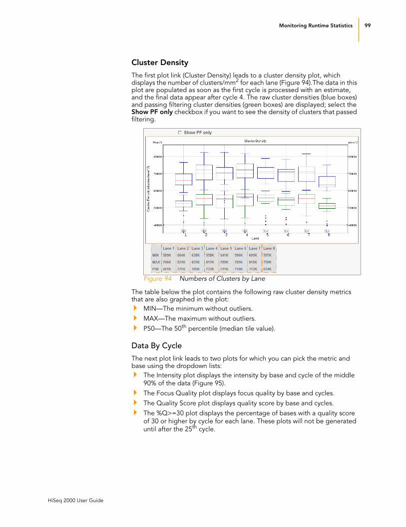
Monitoring Runtime Statistics 99
HiSeq 2000 User Guide
Cluster Density
The first plot link (Cluster Density) leads to a cluster density plot, which displays the number of clusters/mm2 for each lane (Figure 94).The data in this plot are populated as soon as the first cycle is processed with an estimate, and the final data appear after cycle 4. The raw cluster densities (blue boxes) and passing filtering cluster densities (green boxes) are displayed; select the Show PF only checkbox if you want to see the density of clusters that passed filtering.
Figure 94 Numbers of Clusters by Lane
The table below the plot contains the following raw cluster density metrics that are also graphed in the plot:
MIN—The minimum without outliers.
MAX—The maximum without outliers.
P50—The 50th percentile (median tile value).
Data By Cycle
The next plot link leads to two plots for which you can pick the metric and base using the dropdown lists:
The Intensity plot displays the intensity by base and cycle of the middle
90% of the data (Figure 95).
The Focus Quality plot displays focus quality by base and cycles.
The Quality Score plot displays quality score by base and cycles.
The %Q>=30 plot displays the percentage of bases with a quality score
of 30 or higher by cycle for each lane. These plots will not be generated
until after the 25th cycle.

100 CHAPTER 5
Real Time Analysis
Catalog # SY-940-1001
Part # 15011190 Rev. D
The Error Rate plot displays the calculated error rate for each lane, as
determined by alignment to PhiX of a PhiX control sample. The data in
this plot are populated after cycle 25. If no PhiX control sample is run in
the lane, this chart may show an artificially high error rate, accompanied
by a very low (close to zero) percentage of fragments aligned to the PhiX
control. This is normal behavior.
Scroll to the right to view later cycles.
Figure 95 Intensity by Color and Cycle

Real Time Analysis Output Data 101
HiSeq 2000 User Guide
Real Time Analysis Output Data
RTA output results are saved on the analysis server you specified during the run configuration. This section describes the purpose and location of the output data.
Real Time Analysis Folder
The figure below illustrates the organization of the network analysis folder, including the location of the most important output files. All analysis results are saved in an analysis folder that is given the same name as the Run folder on the instrument computer.
;
Figure 96 Real Time Analysis Folder
Analysis Results The analysis folder contains the following key files:
Key File Subfolder Description
Status.xml AnalysisFolder\Data Contains run and analysis-specific metrics generated during the run. See Status Page on page 95 for a description of the metrics.
BustardSummary.xml AnalysisFolder\Data\ Intensities\Basecalls\
Contains run- and analysis-specific metrics generated after base calling.
*.bcl files AnalysisFolder\Data\ Intensities\Basecalls\ L00X\CX.X
Each *.bcl file contains RTA base calling and base quality scoring results for one cycle, one tile. These files are used by the BCL Converter; for a description, see Main Sequence Output Files on page 102.
*.stats files AnalysisFolder\Data\ Intensities\Basecalls\ L00X\CX.X
*.stats files contain RTA base calling statistics per cycle, per tile. These files are used by the BCL Converter.

102 CHAPTER 5
Real Time Analysis
Catalog # SY-940-1001
Part # 15011190 Rev. D
Tile Numbering
Tile-specific files contain the tile number in the file name. The logic of tile numbering in a lane is as follows:
Tiles 1–8 are from swath 1 of the top surface
Tiles 21–28 are from swath 2 of the top surface
Tiles 41–48 are from swath 1 of the bottom surface
Tiles 61–68 are from swath 2 of the bottom surface
A swath is a column of tiles, and there are two swaths per lane per surface.
Main Sequence Output Files
The main sequence output files from RTA are the *.bcl and _qseq.txt files. Bcl files are generated every cycle, for each tile, and can be moved off the instrument and used for analysis once a cycle is fully analyzed. _qseq.txt files are generated once a read is complete, and contain the base calls and quality scores for all cycles of one read for each tile.
*.filter files AnalysisFolder\Data\ Intensities\Basecalls
*.filter files contain filter results per tile. These files are used by the BCL Converter.
SampleSheet.csv AnalysisFolder\Data\ Intensities\Basecalls\
Contains sample information, including multiplexing information.
config.xml AnalysisFolder\Data\ Intensities\
AnalysisFolder\Data\ Intensities\Basecalls\
Contains meta-information about the run, image analysis, and base calling.
RunInfo.xml AnalysisFolder\ Identifies the boundaries of the reads (including index reads), the Flowcell ID (if available), and the quality table selected for run.
ErrorLog.txt AnalysisFolder\Data Any error during an HCS real time analysis run is captured here. If there are no errors, no ErrorLog.txt file will be present.
CopyLog.txt AnalysisFolder\Data All copy events during an HCS real time analysis run are captured here.
*.cif files AnalysisFolder\Data\ Intensities\L00X\CX.X
Each binary *.cif file contains RTA image analysis results for one cycle, one tile. These files should be used in the OLB analysis software if you want to perform BUSTARD base calling; for a description, see the Off-line Base Caller User Guide.
*_pos.txt files AnalysisFolder\Data\ Intensities\
Reports the cluster coordinates. There is one *_pos.txt file for each tile. These files should be used in the OLB analysis software if you want to perform BUSTARD base calling.
*.jpg files AnalysisFolder\ Thumbnail_Images\ L00X\CX.X
HCS can generate thumbnail images (*.jpg files) of nine locations from each tile. The thumbnails are generated for each cycle and base, and can be used to troubleshoot a run. For more information, see Thumbnail Images on page 103.
Key File Subfolder Description

Real Time Analysis Output Data 103
HiSeq 2000 User Guide
*.bcl files
A *.bcl file contains base calls and quality scores for one cycle and one tile. The *.bcl files are in binary format and need to be converted to the _qseq.txt
format in OLB by the BCL Converter (see the BCL Converter User Guide).
Stats files
The Stats file is a binary file containing base calling statistics; the data is for clusters passing filter only. These files are used by the BCL Converter.
Filter files
The *.filter files are binary files containing filter results. These files are used by the BCL Converter.
Thumbnail Images
You can configure HCS to generate thumbnail images (.jpg files) from each swath. The thumbnails are generated for each cycle and base.
HCS combines images from nine sections of a swath. These nine images are combined in one thumbnail image (see Figure 97), and can be used to troubleshoot a run. The thumbnail images are not suitable for image analysis.
Figure 97 Thumbnail Image
Analysis Viewer The metrics generated by RTA can also be viewed from a remote location using the Analysis Viewer application, available through iCom.illumina.com. The files are located in the Interop directory. This viewer uses the same format to display the metrics as run overview screen in HCS (see Monitoring the Run on page 65).
Tile Thumbnail image

104 CHAPTER 5
Real Time Analysis
Catalog # SY-940-1001
Part # 15011190 Rev. D

HiSeq 2000 User Guide 105
Appendix A
Troubleshooting
Topics106 Introduction
106 Troubleshooting
107 Performing a Fluidics Check

106 APPENDIX A
Troubleshooting
Catalog # SY-940-1001
Part # 15011190 Rev. D
Introduction
This section describes how to troubleshoot possible problems encountered during a sequencing run and how to perfrom a fluidics check from the HiSeq start screen.
For issues not described in this section, contact Illumina Technical Support. For more information, see Technical Assistance on page 4.
Troubleshooting
Use the following table to troubleshoot possible problems encountered during a cluster generation run.
Table 14 Troubleshooting Run Problems
Problem Possible Cause Action
Flow cell lever is yellow. The flow cell did not seat properly.
The vacuum did not seal.
Manifolds did not raise.
Remove the flow cell and repeat the cleaning steps.
Ensure the gaskets are present and well-seated.
Reload the flow cell.
The software did not initialize. The software was unable to initialize internal hardware devices.
Close the error message and then relaunch the instrument software.
If the problem persists, restart the instrument computer.
If the problem persists, shut down the instrument, wait a minimum of 60 seconds, and restart the instrument.
Poor fluid delivery. Potential bubbles in the system. Reposition the flow cell and confirm that the holes are facing down.
Look for white precipitate around the gaskets. Always replace gasket before loading a new flow cell.
Confirm that the sipper assemblies are fully lowered and each sipper is in contact with the reagents.
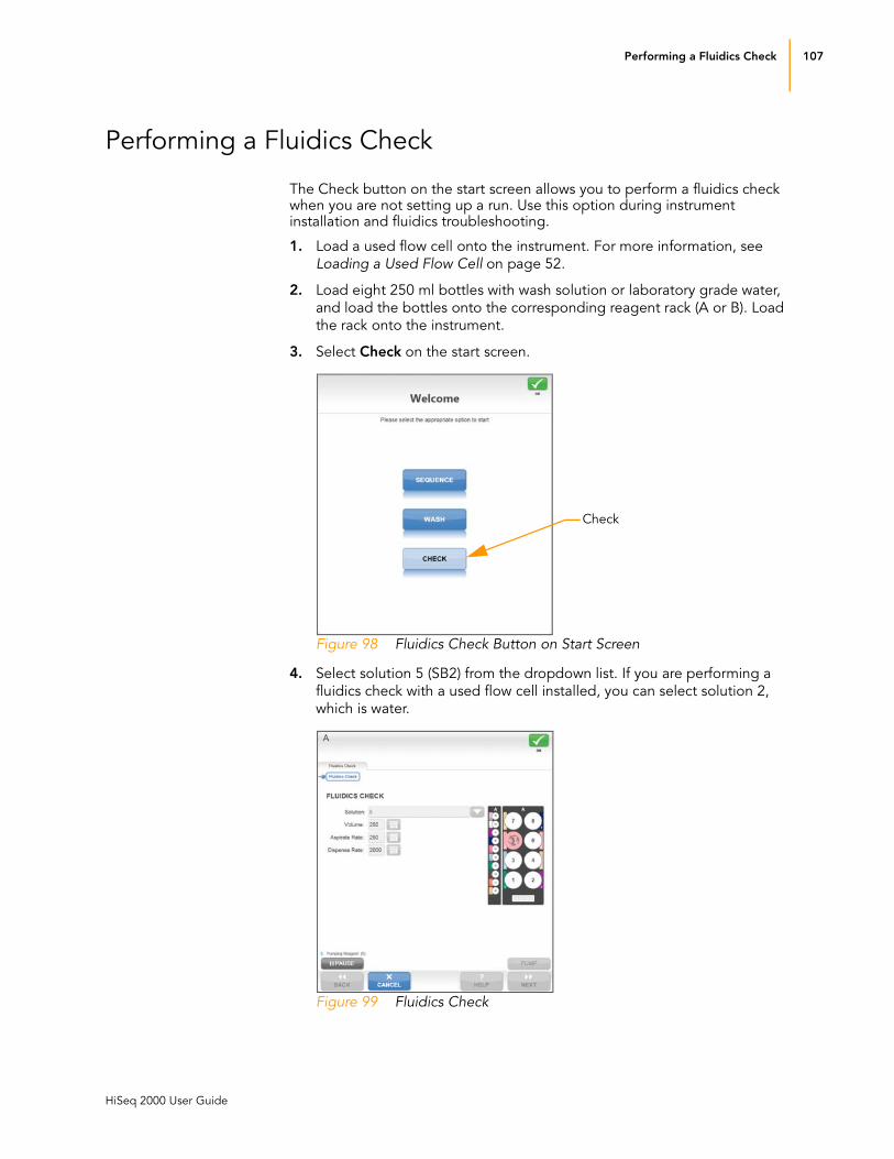
Performing a Fluidics Check 107
HiSeq 2000 User Guide
Performing a Fluidics Check
The Check button on the start screen allows you to perform a fluidics check when you are not setting up a run. Use this option during instrument installation and fluidics troubleshooting.
1. Load a used flow cell onto the instrument. For more information, see
Loading a Used Flow Cell on page 52.
2. Load eight 250 ml bottles with wash solution or laboratory grade water,
and load the bottles onto the corresponding reagent rack (A or B). Load
the rack onto the instrument.
3. Select Check on the start screen.
Figure 98 Fluidics Check Button on Start Screen
4. Select solution 5 (SB2) from the dropdown list. If you are performing a
fluidics check with a used flow cell installed, you can select solution 2,
which is water.
Figure 99 Fluidics Check
Check

108 APPENDIX A
Troubleshooting
Catalog # SY-940-1001
Part # 15011190 Rev. D
5. Enter the following default values:
• Volume: 250
• Aspiration Rate: 250
• Dispense Rate: 2,000
6. Select Pump. If you need to pause the fluidics check, select Pause.
7. Visually inspect the flow cell for bubbles passing through the lanes and
leaks near the manifolds.
If you see excessive bubbles, check the gaskets for obstructions, reduce the aspiration rate to 100, and pump another 250 μl of water to the flow cell. For more information, see Troubleshooting on page 106. If prob-lems persist, contact Illumina Technical Support.

HiSeq 2000 User Guide 109
Index
A
activity indicators 16
analysis folder 101
analysis results 101
B
base calling results 33
BustardSummary.xml 101
C
cif files 101, 102
clusters
measuring intensity 96
components
flow cell compartment 5, 7, 52
fluidics compartment 5optics module 5reagent compartment 5, 6, 47, 75,
83
config.xml 33, 102
consumables
HiSeq Sequencing Kit 10
Illumina sequencing kits 8Multiplexing Sequencing Primers
and PhiX Control Kit 12, 43
Read 2 Cluster Resynthesis Kit 11
user supplied 9customer support 4
D
data transfer 94
disk space, checking 34
documentation 4
F
first-base incorporation
confirmation 19, 27, 44, 69
report location 19, 32
flow 59
flow cell
cleaning 60
loading 23, 24, 52, 58
recording flow cell ID 18
troubleshooting 106
flow cell compartment 5, 7, 52
flow cell lever 54, 61
fluidics check 23, 25, 55, 63
fluidics compartment 5fluidics, troubleshooting 106
focus
quality 99
funnel caps 8
H
help, technical 4HiSeq Control Software 15–34
I
images
saving images samples 19
thumbnails 19
indexing parameters screen 21, 46
L
loading reagents 22, 47, 71, 75, 77, 83
M
maintenance wash 16, 82, 84
manifold gaskets 8metrics
cluster intensity 96
monitoring 65
cluster intensities 65
image samples 67
run fluidics 67
multiplexed sequencing
indexing parameters screen 21
reagents 12, 72
reagents, loading 50

110 Index
Catalog # SY-940-1001
Part # 15011190 Rev. D
reagents, preparing 43
workflow 37
N
numclusters by lane 99
O
optics module 5
P
paired-end sequencing
reagents 11
reagents, loading 77
reagents, preparing 71
workflow 37
Pipeline analysis 94
pos.txt files 102
post-run wash 16, 82, 89
priming
preparation 56
waste volume 57
priming reagents 24
Q
qseq.txt files 103
R
reagent compartment 5, 6, 47, 75, 83
reagent parameters screen 20
reagent positions
flow cell A or B 48
multiplexing 50
paired end 78
reagents
allocating for shorter runs 41
ICR for 101 cycles, preparing 39
loading 22, 47, 50, 75, 77, 83
multiplexing 12, 43, 72
paired end 11, 71, 77
priming 24, 57
reagent parameters screen 20
recording kit ID 20
sequencing 10, 39, 47, 70, 75, 83
real time analysis. See SCS real time
analysis
recipe folder 33
recipe parameters screen 19, 44
reports
cluster intensity 96
first-base incorporation 19, 32, 69
run folder contents 32
review run setup screen 22, 46
RTA. See SCS real time analysis
run folders 32
run overview screen 26, 65
RunInfo.xml 32, 102
S
scan parameters screen 17, 44
SCS real time analysis 94
analysis folder 101
analysis results 101
data transfer 94
focus quality 99
numclusters by lane 99
Pipeline analysis 94
quality metrics 95
runtime statistics 95
status page 95
tile status summary 96
sequencing consumables 8, 39, 70
software
HiSeq Control 15–34
initialization 38
troubleshooting 106
status alert icon 17
status page 68, 95
Status.xml 101
status.xml 33
T
technical assistance 4tile status summary 96
troubleshooting 106
U
user-supplied consumables 9
W
washes
consumables, user-supplied 41, 47, 84, 89
delivered volumes 87, 92
maintenance wash 16, 82, 84
post-run wash 16, 82, 89
workflow, sequencing 37


Illumina, Inc.
9885 Towne Centre Drive
San Diego, CA 92121-1975
+1.800.809.ILMN (4566)
+1.858.202.4566 (outside North America)
www.illumina.com