historic american engineering record …
TRANSCRIPT
HISTORIC AMERICAN ENGINEERING RECORD
CHARLESTOWN NAVY YARD, CHAIN FORGE (Smithery)
(Building 105)
HAER No. MA-90-3 Location: Charlestown Navy Yard, Boston, Suffolk County, Massachusetts Building 105 is located at latitude: 42.376258 and longitude:
-71.052419. The coordinate represents the structure’s southwest corner. This coordinate was obtained on August 1, 2013, using Google Earth imagery dated April 9, 2013. Building 105 has no restriction on its release to the public.
Present Owner: Boston Redevelopment Authority (BRA) owns Building 105, but
the National Park Service owns the machines still in the building. Present Use: Not in use. Significance: The Charlestown Navy Yard’s Chain Forge is significant for its
role as the leading manufacturer of anchor chain and anchors for the U.S. Navy in the twentieth century, as well as for the innovations in chain design and manufacture developed by its employees. In particular, the invention of Die-Lock chain by yard employees Albert M. Leahy, Carlton G. Lutts, and James Reid resulted in the designation of Die-Lock chain as the U.S. Navy’s standard and the Charlestown Navy Yard as the U.S. Navy’s supplier. Although production ceased in the 1970s with the closure of the navy yard, the forge retains a nearly complete inventory of the forges, hammers, presses, and other machinery necessary for production. In addition, there are a number of unique extant machines, such as the 1917 Tinius Olsen chain testing machine, one of only two built, and the nearly complete assembly plant for 4-3/4" Die-Lock chain.
Historian: Justine Christianson, HAER Historian, 2013-2014 Project Information: The Historic American Engineering Record (HAER) is a long-
range program that documents and interprets historically significant engineering sites and structures throughout the United States. HAER is part of Heritage Documentation Programs (Richard O’Connor, Manager), a division of the National Park Service, U.S. Department of the Interior. The recording project was undertaken in 2013 in conjunction with Boston National

CHARLESTOWN NAVY YARD, CHAIN FORGE HAER No. MA-90-3
(Page 2)
Historical Park (Cassius Cash, Superintendent). Dana Lockett, HAER Architect, served as project leader. The field work was completed by Kirk Oldenburg (Louisiana State University) and Emily Warren (University at Buffalo), along with Paul Davidson and Daniel DeSousa (Heritage Documentation Programs). Jet Lowe, assisted by Renee Bieretz, produced the large-format photography, and Justine Christianson, HAER Historian, produced the written report.
Special thanks go to David Vecchioli and Brandon Sexton of
Boston National Historical Park for facilitating access to the building and to the park’s archives, and to the staff of the National Archives and Records Administration-Waltham for their assistance.
Related Documentation: Charlestown Navy Yard HAER MA-90 Charlestown Navy Yard, Woodworking Shop (Building 114) HAER MA-90-1 Charlestown Navy Yard, Pier 10 HAER MA-90-7 Charlestown Navy Yard, Shipfitters’ Shop (Building 104) HAER MA-90-30 Charlestown Navy Yard, Central Power Plant (Building 108) HAER MA-90-34 Charlestown Navy Yard, Incinerator (Building 203) HAER MA-90-50 Charlestown Navy Yard, Oxygen Plant (Building 277) HAER MA-90-62 Charlestown Navy Yard, Pier 9 HAER MA-90-67 Charlestown Navy Yard, Pier 11 HAER MA-90-68 Charlestown Navy Yard, Marine Railway HAER MA-90-69 Charlestown Navy Yard, Ropewalk & Tar House
(Buildings 58 & 60) HABS MA-1247-A

CHARLESTOWN NAVY YARD, CHAIN FORGE HAER No. MA-90-3
(Page 3)
Part I. Historical Information
A. Physical History of Building: 1. Dates of Construction: 1900-1904
2. Architect/Engineer: Bureau of Yards and Docks, U.S. Navy 3. Builder/Contractor/Supplier: P.J. McCaffery of Utica, New York, won the
contract for the powerhouse portion of Building 105 on May 18, 1901, while L.L. Leach & Sons of Chicago built the chain forge at a slightly later date.1
4. Original Plans:
In 1900, a complex of buildings for the Charlestown Navy Yard’s Construction & Repair Department, to include Building 105, was developed as part of a larger plan to increase the yard’s facilities.2 The proposed Building 105 consisted of a powerhouse, square in plan, divided into a boiler room and engine room with an adjacent smithery, rectangular in plan, to the east containing forges, hammers, derricks, and bending slabs. The major difference between the proposed Building 105 and the structure as actually built was the addition of a connector building between the powerhouse and smithery.3
Building 105 was constructed of a steel framework and roof trusses with brick
curtain walls. The powerhouse had a floor supported by steel I-beams. The construction drawings and historic photographs show the exterior had Classical Revival detailing that has been somewhat obscured and/or altered over time, although elements remain and are described in the current conditions section of this report.
The powerhouse originally featured a stack in the boiler room and a ridge
vent, as well as skylights in the hipped, slate roof. Paired, arched windows and decorative metal grates provided illumination and ventilation. Double doors topped with arched windows were located at the south end of the west façade as well as the east end of the south façade, while another doorway was
1 L.L. Leach & Sons appears to have bid on a number of government contracts, including a U.S. Post Office in Alleghany, Pennsylvania, the coppersmith shop and foundry at the Philadelphia Navy Yard, and the government building for the World’s Columbian Exposition. 2 A note about the yard name: the historic name is Charlestown Navy Yard, but it was redesignated the Boston Naval Shipyard in November 1945. The historic name of Charlestown Navy Yard will be used in this report, however, in accordance with Boston National Historical Park convention 3 “Proposed Power Station and Smithery,” C&R Dept., Boston Navy Yard, September 26, 1900, Sheet No. 251. All drawings cited in this report are available from Boston National Historical Park Archives, Boston, Massachusetts (hereafter cited as BOSTS Archives). BOSTS Archives also has a large collection of historic photographs of Building 105, which helped inform this report and measured drawings.

CHARLESTOWN NAVY YARD, CHAIN FORGE HAER No. MA-90-3
(Page 4)
located on the north end of the west façade.4 Materials used included rock-face granite for the foundations, copper for the cornices, concrete for the lintels, and brick for the walls with decorative brickwork for the dentils and stringcourses. The interior, as earlier noted, was divided into a boiler room to the north and an engine room to the south by a brick wall, with a doorway providing access between the two spaces. The boiler room contained coal-fired boilers on brick foundations while the engine room had three engines on brick foundations and a compressor on a brick foundation to the east of the engines. Drawings also indicate there was an overhead 10-ton crane in the engine room. Little information has been found about the interior finishes, except the walls were exposed brick. Drawings specify the engine room would have a marble mosaic installed over the concrete floor and that the engine wells would be lined with enameled brick. However, the available historic photographs do not show any evidence of a mosaic floor. Wall-mounted arc lamps were placed along the perimeter.5
The connector building entrance was centered on the south façade. Granite
steps led to the wood door that featured glass panes and was surmounted by a pediment of limestone. Double-hung windows with pediments flanked the door. Drawings specified that the slate-on-cinder concrete roof have a 3" to 1' pitch. A clerestory of ten-light pivot windows and a circular ventilator topped the building. The connector building contained offices, toilets, lockers, and washrooms. The entrance to the connector building opened into a vestibule flanked by two offices. The remainder of the first floor of the connector building was divided into a lavatory for the powerhouse and a lavatory for the chain forge. Between the lavatories and the offices was a washroom with sinks for forge workers. The second floor was used for storing dies, while the third floor contained a water tank, presumably gravity operated given its location. Information on the interior finishes has not been found.6
The original configuration of the chain forge consisted of a central high bay
with a two-story transept running from north to south and one-story aisles along the north and south facades. This layout resulted in the building being referred to as a “Cathedral of Industry.”7 The north and south aisles used Howe roof trusses, while the center bay roof truss was also a Howe with a rounded bottom chord. The monitor utilized cross bracing. The roofs of the
4 The directions used in this report are not the true cardinal directions, in which the north elevation would actually be the northwest elevation. This is in keeping with BOSTS convention, as well as an effort to simplify the description. 5 Building No. 105, C&R, Power House at West End of Smithery, “Floor and Foundation Plan,” December 10, 1900, Sheet 3 of 8; “Ventilator, Cross Section, & Skylight,” December 10, 1900, Sheet 4 of 8; “Framing Plans and Details of Truss A,” Sheet 5 of 8, January 23, 1901, BOSTS 13403, 105-9. 6 Building No. 105, Smithery, “Wiring Diagram for Electric Lighting,” January 15, 1903, and Building No. 105, Smithery for Dep’t of C and R, “Longitudinal Section through Connecting Building between Power House & Smithery,” March 1902, Sheet 6 of 35. 7 Stephen P. Carlson, Charlestown Navy Yard Historic Resource Study (Division of Cultural Resources, Boston National Historical Park, National Park Service, U.S. Department of the Interior, 2010), 77.

CHARLESTOWN NAVY YARD, CHAIN FORGE HAER No. MA-90-3
(Page 5)
aisles were specified as 3-1/2" concrete covered with slate at a 3" to 1' pitch. The center bay roof was also 3-1/2" concrete covered with slate but with a 6" to 1' pitch. It had skylights and a clerestory of multi-light windows with a roof of slate on cinder concrete.
The forge’s fenestration consisted of groups of arched windows divided by
brick columns on the lower level, while the upper level of the central bay had groups of three, multi-light pivot windows separated by brick piers. The transept gable end, centered on the north façade, had an arched entrance with sliding doors topped by a decorative metal grille. The entrance was flanked by pairs of brick columns, single paneled doors, and arched windows. A granite plaque with “105” carved in it was centered over the entrance, and a circular window in granite trim was located in the gable. Double doors were also located on the east façade, but a rolling steel shutter filled in the arched opening above the doors. Flanking the double doors were pairs of brick piers with single paneled doors between them and granite plaques with “105” carved in them above the doors. A circular window in granite trim was located in the gable. An overhead crane rail on the east facade extended from Building 105 to Building 106 across the street. The gabled transept on the south façade also had a crane rail that connected to Building 104 across the street, as well as double doors topped by decorative metal grilles. Flanking the double doors were single paneled doors. The exterior detailing of the forge mirrored that of the powerhouse, and the materials were the same, including the use of rock-face granite for the foundation.8
The interior of the chain forge was open aside from steel column supports.
The interior was minimally finished, with exposed brick walls and dirt floors. A 1915 memorandum indicates that the chain forge interior had been cleaned by painting the brick walls white to brighten the space, adding windshields to the furnaces, and oiling and rolling the dirt floor to cut down on the dust.9
5. Alterations and Additions:
Throughout its period of operation, changes were made to both the powerhouse and chain forge to accommodate production. In addition, there has been significant movement of machinery and installation of new machines as chain-making technology changed during the period of operation.
8 Building No. 105, Smithery for Dep’t of C. and R., “North-East Elevation,” March 22, 1902, Sheet 3 of 35; “Central Portion, North West Elevation,” March 22, 1902, Sheet 4 of 35; “South-East Elevation,” March 22, 1902, Sheet 5 of 35; “Longitudinal Section through Connecting Building between Power House & Smithery,” March 1902, Sheet 6 of 35; “Half Sections of NE & SW Ends,” March 22, 1902, Sheet 11 of 35; Building No. 105, “Plan Showing Alterations in South West Front,” August 15, 1904, Sheet 97. 9 Memorandum for Master Shipsmith, Subject: Appearance of Shipsmith Shop, July 23, 1915, in Folder 6111-105, in Box 264, 6111-63 – 6112, 1915, and Memo to Commandant, Subject: Painting and Whitewashing Bldg 105, in Folder 6111-105, in Box 149, 6111-28 – 6112-43, 1913, both from Record Group 181, National Archives and Records Administration, Northeast Region-Waltham, Massachusetts (hereafter cited as RG 181, NARA-Waltham).

CHARLESTOWN NAVY YARD, CHAIN FORGE HAER No. MA-90-3
(Page 6)
The first significant alterations took place in the 1910s as a result of the 1913 consolidation of the chain forge and smith shop into one at Building 105 and the shift from hand to power forging. This resulted in the dismantling and rebuilding of plate and angle furnaces, removing most of the hand forging fires, and rearranging and installing additional forging equipment. A 1914 memo indicated that the installation of a 6" upsetting machine for bending bolts before scarfing in a 2,500-pound drop hammer, along with more furnaces and a trimming press, “is sufficient to take care of the scarfing of chain bolts, and also do such current drop forging work as required of the 2,500-pound steam hammer.” (Scarfing refers to the process of flattening the edges prior to welding.) North of this plant was a 100-ton hydraulic press, furnace, and crane for bending links after scarfing. Next to it in the east end of the shop was a chain welding plant consisting of one 1,800-pound steam drop hammer, two 250-pound single-frame forging hammers, two fires, and two cranes. The chain welding plant was expected to “turn out about as much chain as five hand forges formerly turned out.” The chain forge also contained an area for annealing, testing, and painting chain. No changes were made to the south side of the shop, where there was vacant space for chain testing and repair.10 Additional equipment was installed again in 1916 to accommodate the production of 3-3/8" chain, a larger size than had been produced up to that time.11 The 3,000-pound hammer already in place could only handle up to 3-1/4" chain, and the two 1,800-pound hammers were used to manufacture the 2-3/4" and smaller-sized chain. To augment the 6,000-pound and 7,800-pound hammers already in place for making chain appendages, the shop proposed purchasing a 2,500-pound hammer and a 250-pound single-frame forging hammer for installation in the center of the shop, under the overhead cranes used to attach special end links to completed shots (a shot is a unit of measurement of anchor chain and is 15 fathoms, or 90', long). In addition, jib cranes were added at the heavy forge fires and anvils where hand finishing was done.12
10 Memo to Commandant, Subject-Arrangement of Shipsmith Shop, November 23, 1914, quotes from page 2, and Memo to Secretary of the Navy (Division of Material) VIA Bureau of Construction and Repair, Subject: Removal of fires in Building No. 105 (Smithery) used in connection with hand-made chain, October 21, 1914, both in Folder 6112-105, in Box 280, 6111-34 – 6112-106; Memo to Commandant, Subject: Relative award of contract under Schedule 5531, Class 202-Dismantling and rebuilding plate and angle furnaces, Navy Yard, Boston, June 26, 1913, and Memo to The Commandant, Boston, Subject: Requisition No. 51-C&R, Boston Yard, May 1, 1913, both in Folder 1913, 6112-105, Bldg #105, Equipment, in Box 150, 6112-61 – 6153; “Inspection of Navy Yard, Boston, Mass. Friday, May 2, 1913 (PN) by Board of Inspection for Shore Stations,” in Folder 6B-Public Works, General 1913, in Box 148, 565-6111 – 64, 1913, all from RG 181, NARA-Waltham. 11 Anchor chain is referred to by the thickness of the metal forming the links; i.e. 3-3/8" chain is made of 3-3/8"-diameter bars. 12 Memo to Bureau of Construction and Repair, Subject: Additional jib cranes for Shipsmith Shop, Bldg 105, November 30, 1915, and Memo to Commandant, Subject: Equipment for chainmaking, January 8, 1915, both in Folder 6112-105, in Box 266, 6112-105 – 6152; Memo to Bureau of Construction and Repair, Subject: Additions to

CHARLESTOWN NAVY YARD, CHAIN FORGE HAER No. MA-90-3
(Page 7)
A significant addition to the forge was a 2,000,000-pound capacity Tinius Olsen chain-testing machine dating to ca. 1917. The original testing machine only had an 800,000-pound capacity, and as the U.S. Navy began production of larger chain, it became apparent that a higher-capacity machine was needed. The “high pulls” of the 3-1/2" chain testing “are too close to the maximum capacity of the machine for regular service, as they bring a strain on the machine very near its possible maximum, so that even if the triplet does not break, the strain put on the machine is very great; and if the triplet breaks, the machine is subjected to severe shock, frequently throwing the knife edges out of their sockets.” To remedy the problem, the Charlestown Navy Yard proposed shipping their original testing machine to the Puget Sound Naval Shipyard in Washington and installing in its place the Tinius Olsen model. In 1914, the original chain testing machine had been enclosed using materials from Building 40, including corrugated galvanized siding. The completed enclosure measured 24'-6" x about 25', stood 10' tall, and had a slightly pitched roof. The new Tinius Olsen testing machine was also housed in this enclosure.13 During the 1910s, significant changes were made to the powerhouse portion of Building 105. By 1916, the substation was in the process of being removed from the powerhouse in accordance with U.S. Navy orders directing all navy yards to consolidate power plants formerly housed in individual buildings into centralized locations.14 The removal of the power-producing machinery allowed the conversion of that space into other uses. A 1916 memo noted the “consolidation, for economical purposes, of all smith work, including chain manufacture, in Building 105, has been efficient and economical; but the increasing amount of work, and especially the manufacture of drop forgings and chain appendages, makes it necessary to increase the floor space used for smithing purposes.” Thus, the boiler room became a shop extension, and the engine room was converted into a drop forge room. The necessary modifications included removing the boiler room smokestack, repairing and reconstructing the boiler room floor, removing the compressors and foundations, cutting doorways, and installing a crane on the south wall of the boiler room. The estimated cost of the conversion was $25,500.15
chain shop and shipsmith shop, Bldg 105, November 2, 1916, in Folder 6111-105, 1916, in Box 323, 6111-20 – 6111-109, 1916, all from RG 181, NARA-Waltham. 13 Memo to Commandant, Subject: Proposed house over testing machine, Building 105, in Folder 6112-105, 1914, in Box 280, 6111-34 – 6112-106; Memo to Commandant via General Storekeeper, Subject: Req’n for Chain Testing Machine, June 2, 1915, in Folder 6112-105, in Box 266, 6112-105 – 6152, both from RG 181, NARA-Waltham. 14 Memo to Commandant via Construction Officer and Engineer Officer, Subject: Removal of Substation, Bldg 105, November 7, 1916, in Folder 6111-105, 1916, in Box 323, 6111-20 – 6111-109, 1916, from RG 181, NARA-Waltham. 15 Quote from Memo from Naval Constructor W.J. Baxter, Commander Frank Lyon, Civil Engineer R.E. Backenhus, Lieutenant G.T. Swasey (all USN) to Commandant, Subject: Removal of substation, Building 105, February 25, 1916; Memo to Bureau of Construction and Repair, Subject: Additions to chain shop and shipsmith

CHARLESTOWN NAVY YARD, CHAIN FORGE HAER No. MA-90-3
(Page 8)
At some point in the 1910s, the connector building was altered in response to complaints about the inadequacy and less than satisfactory conditions of the toilet and washroom facilities. The use of the second floor for die storage was also causing structural problems, so the toilets, lockers, and washrooms were moved to the building’s second floor while the dies were stored on the first.16 The next period of modifications took place in the 1930s. From 1931-1932, a significant alteration was made to the powerhouse with the conversion of the former engine room into a locomotive and crane repair facility. The original doors and windows on the west façade had to be widened from 11'-6" to 12'-10", while the existing windows were altered into doorways. A concrete floor slab with pits was poured in the former engine room. In 1931, a standing-seam copper roof was installed to replace the original slate roof. A Works Progress Administration project, undertaken around 1936, resulted in an addition at the chain forge’s north façade that was used for shearing steel bars to the required lengths. An historic photograph reveals that the brick shear house had multi-light, double-hung windows. Outside, concrete racks held the steel bars used in chain manufacture.17 More additions and alterations were undertaken as part of the buildup of operations for World War II and subsequent end of locomotive repair in the former powerhouse and return to forging operations. Around 1941, the railroad tracks that had brought locomotives in for repair were removed, a doorway at the north end of the west façade was converted back to windows, and a balcony was installed in the former locomotive and crane repair shop.18 Increased chain production for World War II resulted in extensive changes to the chain forge, with additions built along the north and south facades of the building. (The center bay remained structurally unchanged.) In an example of wartime expediency, the additions were simply constructed around the existing structure while manufacturing continued inside. For the construction of the addition on the north façade of the forge, the shear house and concrete racks were removed. The exterior masonry walls were taken down, but the steel framework was retained. A new 4-ply tar and gravel roof on 2" gypsum
shop, Bldg 105, November 2, 1916; Memo to Commandant, Subject: Increase in chainmaking facilities due to new building program, alterations to Building 105, October 23, 1916, all in Folder 6111-105, 1916, in Box 323, 6111-20 – 6111-109, 1916, from RG 181, NARA-Waltham. 16 Memo to Commandant, Subject: Toilet room, Shipsmith Shop, September 26, 1914, and Memo to Commandant via Public Works Officer, Subject: Toilet Room-Shipsmith Shop, June 30, 1914, in Folder 6112-105, 1914, in Box 280, 6111-34 – 6112-106; Memo from Public Works Officer to Construction Officer, March 22, 1913, and Memo from Construction Officer to Public Works Officer, April 5, 1913, in Folder RG 181 Boston NY-Commandr’s Corresp. 1913, 6112-105, in Box 150, 6112-61 – 6153, all from RG 181, NARA-Waltham. 17 Building No. 105 (South-West End), “Changes Necessary to Convert Existing Building to Roundhouse,” December 14, 1931, PW Drawing No. 105-120. 18 Building 105, “Balcony in Former Roundhouse,” approved July 28, 1941, PW Drawing No. 105-135.

CHARLESTOWN NAVY YARD, CHAIN FORGE HAER No. MA-90-3
(Page 9)
roof planks with an 8" pitch was installed on the addition. The north wing’s second floor walls were clad in Transite (a fireproof, corrugated asbestos cladding) with windows in wood sashes, while the first floor was made up of a series of wood rolling doors set between brick piers.19 The gable end of the north transept was modified to have four wood doors with pivoted wood sash windows above them between brick piers. On the south façade, the existing one-story aisle was extended to two stories. The interior masonry walls were removed but the steel framework and original roof trusses were retained. Building materials were re-used, as seen in the use of the original north aisle roof trusses in the new south aisle’s second-story roof. Since the pitch was the same as the original first-story roof, the metal roofing was also reused, with the addition of 2" gypsum panels. The new second story of the south aisle was clad in Transite, and pivot windows in wood frames were installed.20 Toilet facilities also had to be rearranged to accommodate women working at the chain forge during World War II. An office extension had been constructed in the southwest corner of the forge as part of the 1943 wing extensions. In 1944-1946, alterations were made to this space and to the connector building to create women’s toilets. A doorway was installed in the north wall of the first floor, and wood stairs were built between the forge office and the connector building office. Previous partitions were removed, with only the enclosed office in the connector building (designated the “Master’s Office”) remaining in the southwest corner. A women’s locker and toilet room was located in the east half of the former office toilet, while the west half contained a sink and spiral metal staircase to the men’s washrooms, toilets, and lockers on the second floor of the connector building.21 The final round of significant alterations to Building 105 took place in the 1950s, the result of both modernization attempts by shop master Paul Ivas and the start of 4-3/4" Die-Lock chain production. Ivas described his efforts, with the support of shipyard commander Richard Morgan Watt, as attempts “to bring the thing [chain forge] out of the Dark Ages, as it were.” One such improvement was the installation of a concrete floor in the chain forge around
19 Transite, a fireproof material of asbestos and cement, was manufactured by The Johns-Manville Corporation. It is still in production, albeit without asbestos. 20 Jane Carolan, Charissa Durst, and Roy A. Hampton, Historic Structure Report for Chain Forge (Building 105) Charlestown Navy Yard, Boston National Historical Report, November 9, 2012, 30. See also Building 205, North & South Extensions, “Plan-Lower Level,” August 19, 1943, PW Drawing No. 105-150; “Plan-Upper Level,” August 19, 1943, PW Drawing No. 105-151; “Roof Plan,” August 19, 1943, PW Drawing No. 105-152; “North Elevation & Exterior Doors,” August 19, 1943, PW Drawing No. 105-153; “North Elevation & Exterior Doors,” August 19, 1943, PW Drawing No. 150-155. 21 Building 105, “Masters Office,” June 28, 1946, PW Drawing 105-172; Building 105, “First, Second & Mezzanine Floor Plans,” 1944, PW Drawing 105-167; Building 105, “Women’s Toilet & Locker Room, Plans, Elevations & Details,” May 13, 1944, PW Drawing 105-165.

CHARLESTOWN NAVY YARD, CHAIN FORGE HAER No. MA-90-3
(Page 10)
1952 to replace the dirt one, which not only reduced the amount of dirt and dust but also facilitated the use of forklifts and pallets to move items rather than having to rely solely on the cranes. For workers concerned about the effect of standing on concrete all day, plywood was laid in front of the machines. In those areas were there would be a significant amount of abrasion, steel grating was installed prior to the concrete being poured.22 In addition, Ivas took measures to improve the building’s ventilation. Ernie D. Storlazzi, the yard’s Industrial Hygienist, reported sulphur dioxide levels were as much as 300 percent above allowable limits, resulting in pulmonary problems for workers. In addition, the extreme heat generated by the furnaces would cause the roof tar to melt and drip on the workers. In the blacksmith shop of the powerhouse, Ivas recalled workers had to go home because of the smokiness. Consequently, vent systems on individual furnaces that connected to ducts venting outside were installed, primarily in the auxiliary blacksmith shop in the former powerhouse. To ameliorate the ventilation problems in the forge, Ivas had a continuous ventilator installed on the west half of the roof. Measuring 8' wide x 120' long, it could be adjusted by hand via 40'-long chains extending from the dampers.23 The remainder of the changes to the building resulted from the production of 4-3/4" Die-Lock chain and the need for additional machines to create the assembly plant. The installation of the 25,000-pound drop hammer as part of the new assembly plant required a great deal of foundation preparation. Shop personnel Russ Falardea, George McGoff, and Paul Ivas developed a plan for the foundation that mitigated the effects of its vibrations on Building 105 and neighboring buildings that was based on the foundation for a 20,000-pound hammer installed at drop forging company Wyman-Gordon. In order to locate the hammer foundation, test borings and vibration tests were conducted. The test borings revealed that excavation to a depth of 33' would be required. Once excavation began, workers discovered a 2' layer of clay at the 33' depth, so the additional material was removed to reveal a solid sand, clay, and boulder layer at 35' deep. With the excavation of 1,300 cubic yards of material complete, construction of the foundation could begin.24 The Bureau of Yards and Docks and the Bureau of Ships approved the foundation plan for the forge hammer, and it was built from January to June
22 Paul Ivas, Master of Forge Shop, Boston Naval Shipyard, interview by Arsen Charles, April 24, 1979, 19-20, quote about “Dark Ages” on page 19; Paul Ivas, Master, Forge Shop, interview by Peter Steele and Arsen Charles, August 29, 1978, 12-13, 57, from BOSTS 16364; Pierce Consulting Engineering Company, Concrete Floors-Bldg No. 105, “Plan & Details,” June 3, 1952, Sheet 1. 23 J. M. McCusker Co., Blacksmith Shop, Bldg 105, “Ventilation (Exhaust Air),” June 6, 1952, Sheet 1 of 5, and “Ventilation Details,” June 6, 1952, Sheet 5 of 5. 24 “Installation of 4 3/4" Chain Making Machinery,” typewritten report, no date, 1, in Records of the Boston Naval Shipyard Production Department, Mechanical Shop Group/Forge Shop, Series 45.5 Forge Practice Conference Reports, 1952, from BOSTS.

CHARLESTOWN NAVY YARD, CHAIN FORGE HAER No. MA-90-3
(Page 11)
22, 1953, by Rev-Lynn Contracting Company of Lynn, Massachusetts, with Cdr. A.C. Husband, the Boston Naval Shipyard Public Works Officer, supervising. A 3" layer of sand was laid in the excavated hole. The concrete block on which the furnace sat totaled 24' thick and was poured “monolithically using 3500 lbs per square inch concrete for the first 14 feet 7 inches and 5000 lbs per square inch concrete for the next 3 feet 6 inches to the base of the timber pad.” George McGoff had the idea to drive heavy MZ-38 steel sheet piling to a depth of 50' around the concrete block so there would be at least 10' of piling below the foundation to “prevent lateral flow of the earth from under the foundation.” Next, a 5/8"-thick layer of Fabreeka was placed on the concrete block, followed by five 1' layers of white oak and another 5/8"-thick layer of Fabreeka.25 At the foundation corners, steel hairpin bars with four vertical steel pipes for grouting were inserted to facilitate leveling of the foundation in case of uneven settlement, another idea from McGoff. In total, the foundation required 31 tons of reinforcing steel and 128 tons of sheet-steel piling. The 25,000-pound hammer itself required some modifications, including conversion from steam to air operation and from foot to hand operation.26
B. Historical Context: While a comprehensive history of the Charlestown Navy Yard is beyond the scope of this report, a brief summary is included here, based on Stephen P. Carlson’s comprehensive, three-volume, Charlestown Navy Yard Historic Resource Study produced by the Division of Cultural Resources of Boston National Historical Park in 2010. The Charlestown Navy Yard was one of the original six shipyards established between 1799 and 1801. The other shipyards were located in Washington, D.C.; Brooklyn, New York; Kittery [Portsmouth], Maine; Philadelphia, Pennsylvania; and Norfolk, Virginia. By World War II, additional shipyards were located at Puget Sound, Washington; Mare Island, San Francisco [Hunter’s Point], and Long Beach [Terminal Island] all in California; and Pearl Harbor. The Charlestown Navy Yard was established with President John Adams’ approval on May 9, 1800, on a site consisting of open land and tidal flats. Charlestown, the oldest neighborhood in Boston, lay to the west, having been rebuilt after the Battle of Bunker Hill. The yard grew in size from the initial 35.5 acres acquired in 1800 to 129.88 acres in 1973, most of which resulted from filling in of the waterfront plus the addition of the South Boston Annex. The yard is significant as the site of one of the U.S. Navy’s first two naval dry docks (the other was built at the Norfolk Naval Shipyard). Loammi Baldwin, Jr. designed and
25 Fabreeka was a laminated linen and rubberized material that looked like plywood. 26 “Installation of 4 3/4" Chain Making Machinery,” 3, 6, and quote from page 2; “Mammoth Hammer Forges New Carrier Chain,” no date, in Folder 1, Series 27-Forge Shop, Records of the Boston Naval Shipyard, Department of Shipyard Commander Industrial Relations Office/Equal Opportunity Commission & Employee Relations, 107/2H/1/5, Box 33, BOSTS 13344, and Paul Ivas, interview by Francy Bockoven, December 27, 1984, Final Draft, 31-36, from BOSTS 16364.

CHARLESTOWN NAVY YARD, CHAIN FORGE HAER No. MA-90-3
(Page 12)
supervised construction of both dry docks from 1827-1833. They were designated National Civil Engineering Landmarks in 1977 by the American Society of Civil Engineers. The first ship built at the Charlestown Navy Yard was the USS Independence in 1813; more than 200 warships were built during the yard’s period of operation and thousands more were repaired and maintained. Secretary of the Navy Samuel L. Southard and the Board of Navy Commissioners developed the concept of having each navy yard specialize in manufacturing a particular item for the entire U.S. Navy in the late 1820s, although private American companies later called this policy into question. The Charlestown Navy Yard at first specialized in producing rope at the Ropewalk, the only facility of its type operated by the U.S. Navy, and then Die-Lock anchor chain at the chain forge in Building 105. By the early 1890s, the Charlestown Navy Yard was a “moribund and outdated facility,” but appropriations beginning in 1899 allowed for modernization and construction of a new cluster of buildings for the Construction and Repair Department, including Building 105. Unlike earlier construction projects, the Bureau of Yards and Docks in Washington, D.C., was responsible for the building designs.27 The navy’s Office of the Civil Engineer stated,
the construction proposed to be used in all of the buildings…is to be as near as fireproof as possible, and unless specifically mentioned under each building, the construction will consist of pile and concrete foundations, steel frames, granite water table, brick walls, limestone sills and trimmings, copper cornices and conductors, reinforced concrete floors with maple wearing surfaces, concrete roofs covered with slate, wooden doors, sash and frames, double thick window glass in windows, and metal frame skylights with ribbed glass and screens.28
The land on which the new Construction & Repair Department buildings were to be located was in the vicinity of the landing by British troops in advance of the Battle of Bunker Hill in June 1775, an event marked by a plaque on Building 105. The first structure on the site of what would be Building 105 was the timber Grindstone House (Building 65) that stood from 1867 to 1889. In 1872, the L-shaped Timber-Bending Mill (Building 66) was erected at the site to house a timber-bending machine invented by John W. Griffiths. This machine was used to manufacture curved timbers for ship hulls, but with the shift by 1890 to steel-hulled vessels, the mill was simply used for storage. The Construction & Repair Department took the opportunity to convert the unused Timber-Bending Mill into an Iron Platers Shop in 1891, with a pattern shop on the ground floor and a shipfitters shop on the second. Although a fire destroyed the upper part of the Iron Plater’s Shop in 1899, the navy repaired and expanded the building. As part of a larger yard modernization effort, the Construction &
27 More information about the U.S. Navy’s shipyards and the Charlestown Navy Yard can be found in the comprehensive Charlestown Navy Yard Historic Resource Study by Stephen P. Carlson and produced by the Division of Cultural Resources, Boston National Historical Park, National Park Service, U.S. Department of the Interior in 2010. 28 U.S. Navy Office of the Civil Engineer, Annual Report of Expenditure and Operations, 1904, 45, quoted in Carolan, Durst, and Hampton, Historic Structure Report, 22.

CHARLESTOWN NAVY YARD, CHAIN FORGE HAER No. MA-90-3
(Page 13)
Repair Department began developing a complex of three buildings to include a Shipfitters Shop (Building 104), Smithery (Building 105), and Metalworkers Shop (Building 106). The Bureau of Yards and Docks designed all three buildings in a Classical Revival style. 29 Funding for the proposed complex that included Building 105 was authorized on June 7, 1900, as part of the FY 1901 Naval Appropriations Act. Construction began in 1901 with the erection of a temporary powerhouse at the west end of the site, since each complex or building in the navy yard had to have its own power source. The construction of the powerhouse portion of Building 105 was awarded to P. J. McCaffery, who erected the permanent power plant’s steel structure around the timber powerhouse followed by the brick curtain walls. Just as the power plant was being completed in 1903, however, Congress mandated the consolidation of power plants at navy yards. For a short period of time, the powerhouse held the steam power plant supplying compressed air and generating electricity for buildings 104, 105, 106, 114, and 125 (those buildings used by the Navy’s Department of Construction and Repair). In 1908, in compliance with Congressional direction, the Boston Navy Yard consolidated its power plants into Building 108. While some equipment remained in Building 105’s powerhouse to provide backup power and to supply compressed air, the space was available for a new use. The Public Works Department may have used the former powerhouse for storage from 1908 to 1916, with the smith shop utilizing it from 1916 through the 1920s. By 1931, though, the south room was being converted for use as a locomotive and crane repair shop, while smithing was consigned to the north room. Meanwhile, in 1902, L.L. Leach & Sons, who had also won the contracts for Buildings 104 and 106, was awarded the construction contract for the smithery (later the chain forge) portion of the building. Construction was completed in 1904.30 Initially, hand-forged marine hardware was made in Building 105’s smithery while chain was produced in the Anchor and Chain Shop (Building 40), overseen by the Equipment Department. As earlier noted, the Charlestown Navy Yard had been designated the navy’s supplier of chain in the late 1880s, and machinery was transferred from the Washington, D.C. Navy Yard to Boston for that purpose. A 1912 reorganization led to the closure of the Anchor and Chain Shop. Chain making and other forging was transferred from the Equipment Department’s purview to the Bureau of Construction & Repair, along with personnel from the Anchor and Chain Shop, leading to the consolidation of all forging and consequently a rapid growth in operations. At that time, the forge in Building 105 began producing wrought-iron, hand-welded chain of all sizes by hand using round iron bars produced at the yard’s rolling mill. The shop also produced anchors, described in a 1910 article. The anchors, ranging in size from 400 to 17,500 pounds, were forged using scrap iron. The crown (bottom part) and shank (vertical part) were forged, heated in separate fires, and box welded. The stock and shackle (top part of the anchor) were manufactured
29 Carolan, Durst, and Hampton, Historic Structure Report, 21; “Building 105 (Forge Shop/Roundhouse),” in Carlson, Charlestown Navy Yard Historic Resource Study, Volume 2, 548. 30 Carolan, Durst, and Hampton, Historic Structure Report, 21; “Building 105,” Carlson, Volume 2, 548.

CHARLESTOWN NAVY YARD, CHAIN FORGE HAER No. MA-90-3
(Page 14)
separately. It took twenty-seven working days and multiple men to make one 17,500-pound anchor.31 Since Building 105 had the distinction of being the only “chain shop in this country which is equipped for making large chain cables,” the Navy thought it was “a military necessity to improve the chainmaking plant in every way possible, so that its possible output can be largely increased without impairing the excellence of its product in any way.”32 In 1914, the shop began shifting to power forging through the use of steam hammers. This transition increased output; four men working eight hours could produce twenty links by power forging as compared with only twelve hand-forged links using the same number of men in the same amount of time. It also spurred the navy yard’s efforts to experiment with developing stronger chain. As noted in a 1913 report, “by reason of the size and weight of the modern battleship, it is more essential than ever before that reliable cables should be obtained for the Naval Service.”33 By 1916, the forge was engaged in not only chain manufacturing but also in drop forging yard equipment, chain studs for commercial chain, and chain studs for yard-manufactured chain. Because of the expanded forging operations, the former powerhouse was returned to blacksmith operations in 1916. In the early 1930s, with declining forging operations, this portion of the building was converted into a locomotive and crane repair facility, a function it served until the early 1940s when the north half was again converted to blacksmithing to accommodate increased production.34 During World War I, the yard began producing cast-steel chain in which hot, liquid steel was poured into molds. Cast steel soon supplanted wrought iron because it was 50 percent stronger, and the U.S. Navy adopted it as the standard in 1921. While the Norfolk Navy Yard was initially designated as the navy’s cast-steel chain supplier, innovations by Charlestown Navy Yard personnel would soon make it the navy’s sole producer of anchor chain. The establishment in 1916-1917 of the Materials (Metallurgical) Laboratory at the yard in Building 34 helped the Charlestown Navy Yard’s chain forge move to the forefront of chain manufacture. The laboratory was involved in testing materials used in shipbuilding and in other maritime hardware like chain. The laboratory’s 1952 yard publication noted the
31 “Forge Practice Conference,” Boston Naval Shipyard, February 4, 5, 6, 1952, 3-4, in Records of the Boston Naval Shipyard, Production Department, Mechanical Shop Group/Forge Shop, Series 45.5 Forge Practice Conference reports, 1952, from Box 59, BOSTS 13346; “Manufacture of Anchor Chain at the Navy Yard, Boston,” no date, in Folder 1, Series 27-Forge Shop, Records of the Boston Naval Shipyard, Department of Shipyard Commander Industrial Relations Office/Equal Opportunity Commission & Employee Relations, 107/2H/1/5, Box 33, BOSTS 13344; Chester Lucas, “Making Heavy Chain and Anchors for Uncle Sam,” Machinery (February 1910), 449-450. 32 Memorandum from Engineer Officer to Commandant, Subject: Comment on the Report of the Board of Inspection and Survey for Shore Stations as the result of a recent visit to the Boston Navy Yard, June 26, 1913, 2, in Folder: 6A Public Works General, 1913, in Box 148, 565-611-64, 1913, from RG 181, NARA-Waltham. 33 Quote from “Report of Inspection, Navy Yard, Boston, MASS,” June 2, 1913, 13, in Folder 6A Public Works General, 1913, in Box 148, 565-611-64, 1913; Memo to Secretary of the Navy (Division of Material), VIA Bureau of Construction and Repair, Subject: Removal of fires in Building No. 105 (Smithery) used in connection with hand-made chain, October 21, 1914, in Folder 6112-105, 1914, in Box 280, 6111-34 – 6112-106, both from RG 181, NARA-Waltham. 34 Memo to Bureau of Construction and Repair, Subject: Bldg 105-Drop Forge Plant, Re-Arrangement, August 23, 1916, in Folder 6111-105, 1916, in Box 323, 6111-20 – 6111-109, 1916, from RG 181, NARA-Waltham; Carlson, “Building 105,” Volume 2, 550-551.

CHARLESTOWN NAVY YARD, CHAIN FORGE HAER No. MA-90-3
(Page 15)
“union of the Metallurgical Laboratory, working in close collaboration with the Shop, culminated in what many believe to be the most revolutionary development in the history of the Yard”—Die-Lock chain.35 Experimentation by James Reid (Master Blacksmith), Albert M. Leahy (Leadingman Blacksmith), and Carlton G. Lutts (Material Engineer) resulted in “Die-Lock” chain, which was patented on April 8, 1930, with another patent awarded on September 25, 1934, to Carlton G. Lutts and Albert M. Leahy (Reid had died by that time). Their revolutionary design involved alloy-steel links formed of two sections. Section one, as referred to in the patent, consisted of an alloy steel bar bent into a U shape forged with threads on the tapered ends. In later literature, this component of the chain was known as the male or stem member. This section was heat treated to increase its tensile strength. Section five, as the other section was referred to in the patent, was also made from an alloy steel bar bent into a U shape and drop forged in a die that resulted in the ends being punched in to form hollows. This component was later referred to as the female or socket member. The two sections would then be joined together by inserting section one (which was unheated) into section five (which was heated). The hot metal surrounded the threaded ends of section one, securely locking the two components together. Reid, Leahy, and Lutts claimed that this method of manufacture resulted in chain with a tensile strength of 50 to 75 percent greater than other types. Another benefit of the process was that it resulted in the links having smooth outside contours that allowed the chain to easily pass over pulleys and other mechanical hoisting equipment.36 [See Appendix A, Figure 1.] Reid, Leahy, and Lutts also patented the die used in the assembly of Die-Lock chain link, which was approved April 8, 1930. As described in the application, their “improved dies… readily permit the union of the engaged link sections to be carried out after one of the link sections has been connected to a length of previously completed chain” as well as resulting in a smooth exterior finish to the completed link.37 A 1954 patent awarded to Lutts and Leahy improved the original by reducing the possibility of the chain kinking. This was accomplished by increasing the cross section of the unheated section by 17 percent. Not only did this result in less kinking and, therefore, less breaking, but also it made the links stronger. The 1" Die-Lock chain had a proof rating of 75,000 pounds, while the non-kink Die-Lock chain had a rating of 116,000 pounds, an increase of 55 percent.38 Die-Lock chain was even stronger than cast steel and cost less to manufacture; as a result, “the high tensile strength of this chain made it possible to equip vessels with relatively lighter chain than was formerly thought possible, thus allowing for less stowage in chain lockers and
35 “Manufacture of Anchor Chain at the Navy Yard”; Carlson, “Building 34 (Quality Assurance Facility),” Volume 2, 482-485; quote from “Forge Practice Conference,” 4. 36 James Reid [deceased, Margaret Swan Reid-Executrix], Albert M. Leahy, and Carlton G. Lutts, “Manufacture of Chains,” filed August 10, 1926, awarded April 8, 1930, Patent No. 1,753,941, and Carlton G. Lutts and Albert M. Leahy, “Chain Link,” filed September 23, 1930, awarded September 25, 1934, Patent No. 1,974,827. 37 James Reid [deceased, Margaret S. Reid-Administratix], Albert M. Leahy, and Carlton G. Lutts, “Die for the Manufacture of Chain,” filed August 10, 1926, awarded April 8, 1930, Patent No. 1,753,942. 38 Carlton G. Lutts and Albert M. Leahy, “Chain Link and a Nonkink Chain Made from a Plurality Thereof,” filed March 4, 1950, awarded November 9, 1954, Patent No. 2,693,673.

CHARLESTOWN NAVY YARD, CHAIN FORGE HAER No. MA-90-3
(Page 16)
providing a higher safety factor.” A finished link was nearly double the strength of a welded wrought-iron link, according to Leahy and Lutts. In 1926, the first order for Die-Lock chain was completed: fourteen 15-fathom shots of 1" chain for the USS Tern. By 1934, Die-Lock chain had been designated the standard for the U.S. Navy.39 The “first real exhaustive test” of the chain was made by the Bureau of Ships in 1934 on the cruiser USS Trenton, which usually carried 2-1/2" wrought-iron chain with a 10,000-pound anchor. Use of the Die-Lock chain at different anchorages revealed that it was “stronger, more resilient and more economical from every standpoint.”40 By the 1940s, the chain forge was producing Die-Lock chain in sizes ranging from 3/4" to 3-3/4" as part of the war effort [see Table 1]. Table 1: Chain Production Rates41
Chain Size Shots/Month Total Pounds 3/4" – 7/8" 100 50,000 1" – 1 1/4" 660 800,000 1 3/8" - 2" 300 750,000
2 1/8" – 3 3/4" 225 1,800,000 The increased output led to expansion of Building 105 in 1936 with the replacement of the Shear House with a larger one as part of a Works Progress Administration project, and later the erection of a new north aisle and second story addition to the south aisle in World War II. Thomas O’Connor & Company of Cambridge, Massachusetts, won the 1943 contract to expand the aisles.42 The chain forge played a vital role in World War II as “the only plant owned by the Government and administered by the Navy Department manufacturing anchor chain and appendages. Every Battleship, Aircraft Carrier, and Cruiser afloat in the U.S. Fleet, as well as a majority of the Destroyers, Submarines, Escorts, and Auxiliary Craft afloat are equipped with ‘Die-Lock’ anchor chain and appendages made in the Boston Navy Yard.”43 Demand was so high during World War II that even with 550 employees working at a near constant rate the shop could not produce enough Die-Lock chain to satisfy the needs of the entire fleet (both Atlantic and Pacific). According to one oral history, Leahy let the patent rights to St. Pierre of Worcester, Massachusetts, and Baldt Anchor and Chain of Pennsylvania, so they could also supply Die-Lock chain to the U.S. Navy since the forge had difficulty keeping up with demand. When the patent rights expired, St. Pierre stopped making the chain, but Baldt continued, nearly putting the chain forge out of business by the early 1950s. Baldt company history states that on March 14, 1925, the company entered into an agreement with Reid, Lutts, and Leahy that Baldt would have the sole license to manufacture and sell Die-Lock chain and detachable chain royalty free. Reportedly, Lutts even advised Baldt on how to set up its plant. Regardless of how events actually transpired, it is clear that the Charlestown
39 “Forge Practice Conference,” 4; quotes from “History of the Boston Navy Yard,” Chapter 3, in Folder A12, 1945, History of Boston Navy Yard, in Box 5, 1945 from RG 181, NARA-Waltham. 40 “History of the Boston Navy Yard,” Forge Shop Chapter. 41 Data from “History of the Boston Navy Yard.” 42 Carlson, Volume 2, 551. 43 “History of the Boston Navy Yard,” Chapter 3.

CHARLESTOWN NAVY YARD, CHAIN FORGE HAER No. MA-90-3
(Page 17)
Navy Yard’s chain forge was the birthplace of Die-Lock chain and the primary supplier of that chain to the U.S. Navy.44
In 1949, the Bureau of Ships directed the Boston Naval Yard to “consider” obtaining a 20,000-pound drop hammer, 8" upsetting machine, and 225-ton trimming press for use in manufacturing 4-3/4" Die-Lock anchor chain for the new Forrestal class, the U.S. Navy’s first supercarrier class consisting of Forrestal (CV-59), Saratoga (CV-60), Ranger (CV-61), and Independence (CV-62). Capable of 34 knots and operating with a complement of 4,378 crew members, the Forrestal class featured angle decks to accommodate jet aircraft. The massive ships, measuring 990' long at the waterline with 129'-4" beams at the waterline, and a draft of 35'-9", consequently required massive anchor chains. This directive to manufacture 4-3/4" chain for the U.S. Navy was a boon for the chain forge, keeping it in operation for several more years even as private industry had begun manufacturing Die-Lock chain in various sizes. Former employee Ken Mitchell observed that although the U.S. Navy sent invitations to bid on manufacturing 4-3/4" Die-Lock chain to Chrysler, Ford, General Motors, Kaiser, and Baldt, all the companies declined, perhaps because “they figured there wasn’t enough money in it, or there wasn’t enough production involved….They would have to make a ship’s worth of chain, or two ship’s worth of chain, and then they’d have to shut down the plant because there wouldn’t be another ship under construction to warrant making any more chain. So they figured that wasn’t enough work for them.”45 Since the chain forge lacked the necessary machinery to manufacture such large chain, the Bureau of Ships transferred a 25,000-pound drop forging hammer [Navy #230292] and an 8" upsetting forging machine [Navy #230302] from Joint Army-Navy Machine Tools Committee (JANMAT) storage at the Naval Ordnance Plant in Charleston, West Virginia.46 A new 440-ton trimming press was also obtained from an unknown source. The chain forge began production of the 4-3/4" Die-Lock chain in 1953. Each link weighed 360 pounds and measured 2'-4 1/2" x 17 1/4".47
44 Fred C. Perry, “History of Baldt Anchor and Chain,” September 1993, http://www.oldchesterpa.com/baldt_anchor_history.htm, accessed June 24, 2013; and Ken Mitchell, interview by Arsen Charles, March 16, 1979, 2-5, from BOSTS 16364. 45 Interview with Ken Mitchell, March 16, 1979, 3. Mitchell also recalled that Baldt did suggest forging and heat treating the male members and forging and punching the female members of the links at the Ladish Company in Cutty, Wisconsin, and then sending the two halves to the chain forge for assembly. This proposal was not feasible, however, because the female member needed to be heated onsite before assembly. In addition, Mitchell explained that “the socket members have to be pierced onsite, because as the dies wear, it requires a little more material to be added to the length of [illegible] so you would have enough weight in order to make the socket member. If you didn’t have enough weight in there, or enough material, the die wouldn’t fill out, the link wouldn’t fill out in the die….So therefore, if they had all the socket members made in advance, if the die wore a little bit, those links then would never come out right…You have to add the material as the dies wear. In other words, you might have to add only a sixteenth of an inch, or an eighth of an inch, or 3/16 to the length of the bar, in order to make that material flow high enough up on the stem-member end to close the gap,” quote from page 5. 46 The Navy #s indicated in brackets represent numbers assigned to each machine in the building. Readers wanting additional information or specifications can use these numbers to look up additional information about the machines in the appendix at the end of this report. 47 “Installation of 4 3/4" Chain Making Machinery,” 1, 8.

CHARLESTOWN NAVY YARD, CHAIN FORGE HAER No. MA-90-3
(Page 18)
The Boston Naval Shipyard was declared a National Historical Landmark in 1966, with the chain forge designated a contributing structure. The shipyard closed on July 1, 1974, and in July 1978, the General Services Administration awarded 30.91 acres of Boston Naval Shipyard to the Boston Redevelopment Authority for “historic monument purposes,” including Building 105, but not the machinery.48 Initially, the machinery was transferred on paper (not physically) to the Smithsonian Institution, with the exception of one chain assembly plant, but the Smithsonian quickly returned the equipment (on paper only again) to the National Park Service. In 1980, Building 105 was added to the Charlestown Navy Yard unit of the Boston National Historical Park. Nothing was done to the building until April 1995, when James O. McFarland Inc. was awarded a contract to stabilize the structure, including repairing the powerhouse walls and weatherproofing the windows, doors, and skylights. As part of the Department of Defense Environmental Restoration Program-Formerly Used Defense Sites, the U.S. Army Corps of Engineers and contractor Stone & Webster completed remediation work of the building and machines from 1997 to 2002. The Boston Redevelopment Authority has been working to find a developer for the property, but in the meantime, the building remains a time capsule of twentieth-century chain production and forging.49
Part II. Structural/Design/Equipment Information
A. General Statement:
1. Character: Building 105 consists of three distinct sections: powerhouse, connector building, and chain forge with a high center bay and transept. It is a steel frame structure with brick curtain walls and Classical Revival-style detailing. Although additions to the north and south facades of the chain forge and alterations to the entire building have been made, the general character has been retained.
2. Condition of fabric: The machinery is in good condition, albeit moved from its original locations in some cases thanks to reconfigurations of the plant layout to accommodate changes in production and to the 1997-2002 remediation efforts. The building, however, is in poor condition because of the lengthy vacancy. Water damage due to vandalism of the copper roof elements has led to extensive decay in the office spaces of the connecting building, and leaking has also damaged the ceiling of the former powerhouse. Efforts have been made to protect the building from the outside elements and vandalism, including boarding of all windows.
48 Folder: Charlestown Mass. Bldg. Repair Specs. N-Mass-708, Bldgs 104-105, Suppl #11, in Box 24, 06-006, in Record Group 291, Real Property Disposal Case Files, 1977-80, NARA-Waltham. 49 Carlson, “Building 105,” Volume 2, 551-553.

CHARLESTOWN NAVY YARD, CHAIN FORGE HAER No. MA-90-3
(Page 19)
B. Description of Exterior:
1. Overall dimensions: The former powerhouse portion of Building 105 is 110'-2" x 94'-9". The connector building is 26' x approximately 83', while the forge is 328'-5" x 135'-6".50
2. Foundations: All three sections of the building: powerhouse, connector building,
and chain forge, sit on a granite foundation. 3. Walls: Building 105 has curtain walls of red brick laid in American or running bond.
The former powerhouse, connector building, and the original portions of the chain forge retain their decorative brickwork, including dentils and stringcourses at the cornices, columns with capitals between windows, and arch moldings. The World War II-era additions to the chain forge are more utilitarian in nature and are clad in Transite, a corrugated asbestos siding.
4. Structural system, framing: Building 105 has a steel structural frame. The chain
forge framing consists of riveted I-beam columns sitting on concrete foundations on either side of the central bay that are spaced approximately 39-1/2' apart, except at the transept where they are 52' apart. The columns support steel girders that run along either side of the central bay. The north aisle has a Warren roof truss with verticals, the center bay uses an arched Howe truss, and the south aisle has a half Howe roof truss. Lateral bracing and trussing are also used in the monitor of the center bay. The powerhouse framing consists of riveted I-beams as well.
5. Porches, stoops, balconies, bulkheads: The connector building entrance on the
south façade has a stoop with stone steps and cheekwalls.
6. Chimneys/stacks: The former powerhouse has a circular vent on the north side of the roof and two vents on its ridge. The connector building has a copper vent centered on the roof. A circular vent is located on the ridge of the chain forge’s transept. Eight circular ventilators are located on the east half of the chain forge’s monitor. A ridgetop ventilator was installed on the west half of the chain forge roof in the 1950s.
7. Openings:
a. Doorways and doors: The doors have been boarded up, but historic drawings and
photographs, as well as interior evidence, reveal that the former powerhouse originally had a combination of wood, multi-leaf doors with glass windows, and rolling doors. Three doors were installed in the powerhouse’s west end to provide access for locomotives being repaired in the shop. An inset paneled doorway is located at the southeast corner of the former powerhouse. The connector building’s
50 Dimensions based on fieldwork completed in 2013 by the HAER field team.

CHARLESTOWN NAVY YARD, CHAIN FORGE HAER No. MA-90-3
(Page 20)
main entrance is on the south façade. It was originally a multi-leaf wood door with glass windows and an unbroken pediment. Another doorway is on the north façade of the connector building. The chain forge doorways consist of steel roll-up doors along the north façade and pedestrian doors at the south transept. Doorways were also located on the east façade and the north transept.
b. Windows and shutters: The windows have also been boarded up or bricked in, but
historic drawings and photographs, plus interior evidence show that the majority of the building’s original windows were steel and multi-light. In the powerhouse, the windows are generally paired arched and half-round windows. The north and south façades of the powerhouse have pairs of arched windows with brick arch moldings. A decorative grille can be seen above each window, presumably for ventilation. The west façade is divided into six bays by brick columns with either door or paired window openings and single or paired arched window openings above them. The connector building has three arched windows in the north façade. The chain forge has triplets of arched windows separated by brick columns on the first floor of the south aisle, while circular windows can be found in the gable ends. The World War II-era additions to the forge used running multi-light windows in wood frames.
8. Roof:
a. Shape, truss, type, covering: The powerhouse has a hipped, slate roof, while the connector has a slightly-pitched roof. The chain forge has a cross gable roof due to the transept, while the World War II-era additions have shed roofs. The original roof of the chain forge is copper while the addition roofs are gypsum and tar.
b. Cornice, eaves: Building 105 has copper cornices, gutters, and downspouts.
c. Dormers, cupolas, towers, clerestories, monitors: The connector building and chain forge have gabled monitors. The west half of the chain forge roof has a corrugated-steel ridgetop ventilator.
C. Description of Interior:
1. Floor plans: Building 105 is comprised of three distinct sections, the largest of which is the chain forge in the east part of the structure. The west part of the building, which was once the powerhouse, was divided into two rooms (boiler room and engine room) by a brick wall. Later, the north room was converted into a blacksmith shop with a handful of forges remaining, while the south room became a locomotive repair facility with three pits running from west to east. Between the former powerhouse and forge is the aptly-named connector building, which has been altered several times over its period of use. Its last configuration had the first floor containing an office and toilet space (designated for women during World War II) in the south half and die storage and access between the former powerhouse and chain forge in the north half. The second floor held lockers, toilets, showers, and sinks, while additional lockers and a water tank were located on the third floor. The chain

CHARLESTOWN NAVY YARD, CHAIN FORGE HAER No. MA-90-3
(Page 21)
forge is primarily open and houses machinery that was initially arranged according to workflow (additional information about this can be found in later sections of this report). An enclosure centered on the east end of the forge contains the Tinius Olsen chain testing machine, with a pit extending west from it. The only other enclosure can be found in the southwest corner of the building where offices were located.
2. Work flow: The raw material—consisting of steel bars of various sizes depending
on the size of chain to be manufactured—was brought into the chain forge through a doorway and down a ramp at the northwest corner of the building. Hacksaws, shearing machines, and band saws were located in this area to cut the bars to the required lengths. From there, the cut bars would be transported to the appropriate location in the chain forge. The 4-3/4" Die-Lock chain was manufactured in an area along the north side of the shop that was set up in the early 1950s. Six assembly plants for manufacturing smaller Die-Lock chain, sized 3/4" to 2", were located in the northeast corner of the shop. Testing and finishing of the completed chain took place in the southeast corner where the testing machines, Wheelabrator, and paint tanks stood. Production of 3" and 3-3/8" Die-Lock chain was done in the center aisle of the building, while along the south façade the furnaces, presses, and hammers used in making miscellaneous metal hardware, such as detachable couplings, links, drop bolts, and wing nuts, among other things, were located. The male members of the Die-Lock chain in sizes up to 3-1/2" and 4-3/4" were also manufactured in this area.
The work flow of the blacksmith shop in the former power house is not definitively
known due to a lack of physical and textual evidence. Handmade items like tongs, flanges, shackles, and detachable chain were manufactured in this area, so the process was specialized as opposed to the primarily automated power forging operations taking place in the chain forge.
3. Stairways: The stairways in the chain forge are generally concentrated at the
western end by the office, with a straight, wood stairway with plate treads providing access to the second floor. It has a landing at the halfway point supported by cross bracing. Another flight of straight, wood stairs supported by cross bracing is located on the north end of the office space against the west wall. It provides access from the second floor of the office to the second floor of the connector building. Finally, a flight of stairs on the west wall of the chain forge also leads to a doorway to the second floor of the connector building. A ladder with a safety cage rises from the landing of this stairway to the traveling crane overhead.
A spiral metal staircase is located in the connector building’s first floor to provide
access to the second floor washrooms. A short flight of stairs with hand railings in the chain forge office leads to the office located on the first floor of the connector building. A straight metal staircase with open risers adjacent to the chain forge office accesses the second and third floors of the connector building.

CHARLESTOWN NAVY YARD, CHAIN FORGE HAER No. MA-90-3
(Page 22)
4. Flooring: The chain forge and former powerhouse have poured concrete floors. The connector building and the chain forge office have wood floors that were probably clad in some material, but the current conditions of the connector building and office space have made identification impossible.
5. Wall and ceiling finish: The walls of the office enclosure in the chain forge are a
combination of materials, including corrugated metal and asbestos-cement board, reflecting wartime expediency. The exterior and party walls of the chain forge and connector building are exposed brick. The partition walls in the connector building are cement board. The vestibule for the front entrance appears to be wood frame with bead board cladding. The walls of the shower spaces were clad in glazed tile. The die storage space of the connector building has exposed brick walls, as does the former powerhouse.
6. Openings:
a. Doorways and doors: The majority of the interior doorways are simply open, although nearly all are trimmed in wood. Extant doors are only found at the entrance to the first floor of the chain forge office (wood, three panel with glass pane on top), to the connector building’s first floor entrance vestibule (wood, two panel that probably once had a glass pane but is now boarded over, and a glass transom), and to the women’s toilet (wood, two panel with glass pane on top).
b. Windows: Interior windows can be found in the office space of the chain forge and
in the connector building. The “Master’s Office” on the first floor of the connector building features fixed, nine-light windows on either side of the doorway. The washroom portion of the women’s toilet has a window opening, as do the first and second floors of the chain forge office. These were originally bottom-hinged sashes.
7. Mechanical equipment:
a. Heating, air conditioning, ventilation: The office and locker spaces of the connector building were the only spaces that were heated, as evidenced by radiators. Ductwork has also been exposed in the second floor of the connecting building, but its use is not known.
b. Lighting: There is no longer electricity running to the building, but some incandescent ceiling lamps remain in the chain forge.
c. Plumbing: A plumbing system was required in the connector building for the
toilets and washrooms.

CHARLESTOWN NAVY YARD, CHAIN FORGE HAER No. MA-90-3
(Page 23)
d. Pump Room: A metal cage on the west wall of the chain forge enclosed the pump room used to pump fuel oil from storage tanks to the oil-burning furnaces. The pump room was equipped with menometers to track fuel levels.51
D. Machines: There are nearly 140 pieces of machinery in the chain forge, with an additional seven in the blacksmith shop in the former power.52 Most of the machines date to the 1930s, 1940s, and 1950s, installed as part of the buildup of production for World War II and the beginning of Die-Lock chain production. Taken as a whole, the extant machinery reveals shifts in production and the evolution of forging practices and chain manufacture. The yard’s Mechanical and Electrical Maintenance Department was responsible for the installation, repair, and overhaul of all equipment in the shop, except the bridge cranes. They also kept the Tinius Olsen chain testing machine in operation.53
This section provides an overview of the types of machines used in Building 105; the more detailed list of machinery contained within Building 105 is included as Appendix B to this report.
Furnaces The overwhelming majority of extant machines in Building 105 are furnaces (approximately 38 percent). The earliest date to 1900 and 1906 respectively and were supplied by the Rockwell Engineering Company of Blue Island, Illinois [Navy #s 230150, 230151]. Most, however, are attributed to the Boston Navy Yard and date to the 1940s. The majority of the furnaces burned oil, had Hauck burners, and achieved temperatures of 2,100 to 2,300 degrees F as required for forging. The oil-burning furnaces came in a range of sizes to accommodate the various-sized bars and components, and some had double chambers. Oil-burning furnaces are so prevalent in the forge because heating the metal being forged was required at various points in the manufacturing process. With the increased production resulting from World War II, a rotary furnace from Gas Machinery Company of Cleveland, Ohio, was installed [Navy # 230083]. This furnace was able to heat thirty-four bars of 3-1/2"-diameter and 32" long from room temperature to 2,400 degrees F in one hour. The last oil-burning furnaces installed in the chain forge appear to be the two 1953 slot furnaces from the Lithium Company of Newark, New Jersey [Navy #s 230293, 23094]. Measuring 14' long x 9' wide x 10' high, these were some of the largest oil-burning furnaces in use in the forge and thus able to accommodate the 4-3/4" Die-Lock chain in production.
51 Interview with Ken Mitchell, March 16, 1979, 7. 52 Michael S. Raber, Patrick M. Malone, Robert B. Gordon, and William F. Johnson undertook a detailed inventory of the extant equipment and found 162 pieces of mechanical equipment. The results are compiled in “Special Resource Study, Chain Forge Machinery in Building 105, Boston National Historical Park, Charlestown Navy Yard,” prepared for Boston Preservation Alliance, June 2014. Many thanks to Duncan Hay of the National Park Service and others for compiling a detailed inventory consisting of not only the basic machine information (type, date, manufacturer) but also specifications. Cursory field verification of the inventory was done as part of the research for this report, but the remediation and mothballing of the building have resulted in some machines being moved and loss of some of the identification tags from machines. 53 “Forge Practice Conference,” 7.

CHARLESTOWN NAVY YARD, CHAIN FORGE HAER No. MA-90-3
(Page 24)
Once the forge began production of Die-Lock chain in the 1920s, it became apparent that heat treating produced an even stronger link, and electric furnaces were installed for that purpose, initially located in the southeast corner of the chain forge where finishing took place. The earliest extant electric furnace in the chain forge dates to 1930. Supplied by the Electric Furnace Company of Salem, Oregon, the rotary furnace had numerous compartments in which the stem components of the Die-Lock chain were placed for heat treating [Navy # 230045]. Once the components had been in the furnace for the requisite period of time (one rotation), a hydraulic lift raised the pan and dumped the components onto a conveyor leading to nearby quenching tanks of water or oil.54 Lindberg Engineering Company of Chicago, Illinois, supplied a number of electric furnaces used in heat treating, including vertical barrel types with interior diameters of 28" and 48". The 48"-diameter barrels could handle up to 11,000 pounds [Navy #s 230040, 230042, 230109, 230110, 230111]. Lindberg also produced an annealing furnace used in heat treating the Die-Lock chain in sizes up to 1-1/2" [Navy # 230055]. After heat treatment, the chain was dropped into an adjacent oil-quenching tank. A 1952 electric salt bath furnace from Ajax Electric Company of Philadelphia, Pennsylvania, operated with an 18" layer of salt that was heated to a liquid [Navy # 230301]. Salt bath furnaces could quickly and efficiently heat treat metals without exposure to the air.55 Additional electric furnaces for heat treating the stem components of Die-Lock chain were installed at the various chain assembly plants in the forge in the 1950s. This included a 1952 General Electric company model [Navy # 230329] in the northeast corner where the 3/4" to 2" Die-Lock chain was manufactured, and another 1952 87"-diameter General Electric furnace on the south wall where stem Die-Lock components were manufactured, except for the 3-1/2" and 4-3/4" sizes [Navy # 230328].56 Also located on the south wall was a lithium gas-fired furnace from 1953, the only one of its type in the forge. Manufactured by The Lithium Company of Newark, New Jersey, the rotary furnace was heated by thirteen burners of lithium gas and could turn in either direction at a rate of forty minutes to three hours per rotation [Navy # 230287]. A Lithium Company catalog described the advantages of lithium gas-fired furnaces, stating that while controlled atmosphere (airtight) furnaces had been developed, they still allowed water vapor, oxygen, and carbon dioxide into the chambers, causing decarburization. The Lithium Company solved the “baffling problem” of creating a truly controlled atmosphere by using lithium, which “completely neutralizes both water vapor and oxygen in the furnace atmosphere.”57
To handle heavy forging operations, the forge used a 1915 car-bottom furnace from the Quigley Annealing Furnace Company [Navy # 230103]. Items to be heat treated were placed on a railroad car and rolled into the 16'-long x 11'-wide x 12'-high furnace, where they were
54 Interview with Paul Ivas, August 29, 1978, 37-38, and Kenneth J. Mitchell, interview by Arsen Charles, January 11, 1979, 55-56, BOSTS 16364. 55 George E. Totten and Maurice A.H. Howes, eds., Steel Heat Treatment Handbook (Marcel Dekker, Inc., 1997), 459. 56 Interview with Paul Ivas, August 29, 1978, 43-44. 57 The Lithium Company, “Lithium Metallic Vapor Atmosphere Furnaces, Principles and Data,” 1944, from Smithsonian Institution Libraries, Trade Literature Collection.
CHARLESTOWN NAVY YARD, CHAIN FORGE HAER No. MA-90-3
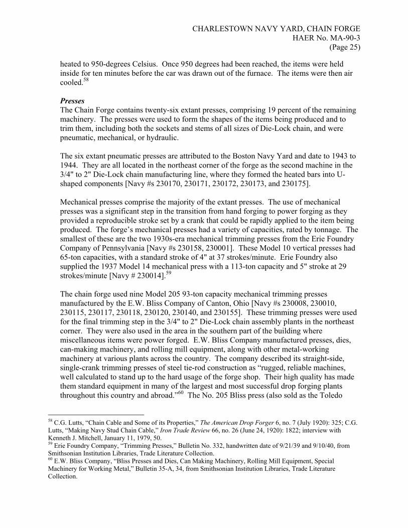
(Page 25)
heated to 950-degrees Celsius. Once 950 degrees had been reached, the items were held inside for ten minutes before the car was drawn out of the furnace. The items were then air cooled.58 Presses The Chain Forge contains twenty-six extant presses, comprising 19 percent of the remaining machinery. The presses were used to form the shapes of the items being produced and to trim them, including both the sockets and stems of all sizes of Die-Lock chain, and were pneumatic, mechanical, or hydraulic. The six extant pneumatic presses are attributed to the Boston Navy Yard and date to 1943 to 1944. They are all located in the northeast corner of the forge as the second machine in the 3/4" to 2" Die-Lock chain manufacturing line, where they formed the heated bars into U-shaped components [Navy #s 230170, 230171, 230172, 230173, and 230175]. Mechanical presses comprise the majority of the extant presses. The use of mechanical presses was a significant step in the transition from hand forging to power forging as they provided a reproducible stroke set by a crank that could be rapidly applied to the item being produced. The forge’s mechanical presses had a variety of capacities, rated by tonnage. The smallest of these are the two 1930s-era mechanical trimming presses from the Erie Foundry Company of Pennsylvania [Navy #s 230158, 230001]. These Model 10 vertical presses had 65-ton capacities, with a standard stroke of 4" at 37 strokes/minute. Erie Foundry also supplied the 1937 Model 14 mechanical press with a 113-ton capacity and 5" stroke at 29 strokes/minute [Navy # 230014].59 The chain forge used nine Model 205 93-ton capacity mechanical trimming presses manufactured by the E.W. Bliss Company of Canton, Ohio [Navy #s 230008, 230010, 230115, 230117, 230118, 230120, 230140, and 230155]. These trimming presses were used for the final trimming step in the 3/4" to 2" Die-Lock chain assembly plants in the northeast corner. They were also used in the area in the southern part of the building where miscellaneous items were power forged. E.W. Bliss Company manufactured presses, dies, can-making machinery, and rolling mill equipment, along with other metal-working machinery at various plants across the country. The company described its straight-side, single-crank trimming presses of steel tie-rod construction as “rugged, reliable machines, well calculated to stand up to the hard usage of the forge shop. Their high quality has made them standard equipment in many of the largest and most successful drop forging plants throughout this country and abroad.”60 The No. 205 Bliss press (also sold as the Toledo
58 C.G. Lutts, “Chain Cable and Some of its Properties,” The American Drop Forger 6, no. 7 (July 1920): 325; C.G. Lutts, “Making Navy Stud Chain Cable,” Iron Trade Review 66, no. 26 (June 24, 1920): 1822; interview with Kenneth J. Mitchell, January 11, 1979, 50. 59 Erie Foundry Company, “Trimming Presses,” Bulletin No. 332, handwritten date of 9/21/39 and 9/10/40, from Smithsonian Institution Libraries, Trade Literature Collection. 60 E.W. Bliss Company, “Bliss Presses and Dies, Can Making Machinery, Rolling Mill Equipment, Special Machinery for Working Metal,” Bulletin 35-A, 34, from Smithsonian Institution Libraries, Trade Literature Collection.

CHARLESTOWN NAVY YARD, CHAIN FORGE HAER No. MA-90-3
(Page 26)
Press No. 55 ½) used in the chain forge had a 1,800-pound hammer with a 4" to 10" stroke and operated with a 7.5-horsepower motor. Higher-capacity mechanical presses can be found in various locations throughout the chain forge. One such press is located east of the 10,000-lb drop hammer in the center bay, where the 3" and 3-3/8" heavy-duty chain was produced. E.W. Bliss Company supplied this 255-ton capacity mechanical press [Navy # 230091]. This model (no. 208, also sold as Toledo Press No. 58 ½) had a 7,000-pound hammer with a 7" to 16" stroke and required a 20-horsepower motor.61 A 1943 Model 7C, 700-ton press from the Ajax Manufacturing Company can be found near the hack and band saws in the northwest corner of the forge [Navy # 230152]. J.R. Blackeslee, Sr. founded the Ajax Manufacturing Company of Cleveland, Ohio, in 1875. At first, the company produced bolts, nuts, rivets, and spikes, but by 1888, it had shifted to manufacturing forging equipment. According to company literature, Model 7C was a solid-frame forging press with an approximate weight of 68,000 pounds that was capable of 60 strokes/minute. The press was notable for its “massive, rigid solid steel frame, all in one piece and without tie rods, with continuous housings and heavy crown rib to support the over-sized eccentric shaft,” because it could keep “forgings and coinings to surprisingly uniform thickness. The alignment, speed and minimum stretch, with the accompanying brief contact period with the hot metal, result in highly satisfactory die life, which is further benefited through generally striking the forging only once per impression, as against the repeated blows of a hammer.”62 The press operated with a guided ram that pressed the metal into dies, while mechanical ejectors allowed for rapid removal of the forged item from the machine.63 To accommodate forging of the 3" and 3-3/8" Die-Lock chain in the center bay of the forge, three hydraulic presses were installed. These presses operated with pistons that produced the force on the metal rather than hammers. Farquhar of York, Pennsylvania, supplied a 400-ton, double-action press with a 36" stroke [Navy # 230081]. A crane jib could move items between an oil-fired furnace to the north, this press, and a 2,000-pound hammer to the southeast. The press had a 30-horsepower motor and could press 17"/minute. E.W. Bliss supplied a 200-ton Hydro-Dynamic Single Action Housing press (Model HS-200-H) with a 25" stroke [Navy # 230085]. The company noted its presses were “adapted to work where a steady pressure of known intensity must be exerted, such as coining, sizing, embossing, shaping, stamping, extruding; also bending, drawing, reducing, hot and cold forming, forging.”64 A punch descended and put pressure in the middle of the bar being shaped, pushing it between rollers and forming a U shape. When complete, an ejector raised the bent
61 E.W. Bliss Company, “Straight-Side Trimming Presses,” Catalog No. 18, from Smithsonian Institution Libraries, Trade Literature Collection. 62 The Ajax Manufacturing Company, “Ajax Solid Frame Forging Presses, Air Clutch Operated,” Bulletin No. 75, 3, from Smithsonian Institution Libraries, Trade Literature Collection. 63 Quote from The Ajax Manufacturing Company, “Ajax Solid Frame Forging Presses,” 3; The Ajax Manufacturing Company, “The History of Ajax Manufacturing Company,” no date, 5, both from Smithsonian Institution Libraries, Trade Literature Collection. 64 E.W. Bliss Company, “Bliss Hydro-Dynamic Single Action Housing Type Presses,” Bulletin No. 31, 2, from Smithsonian Institution Libraries, Trade Literature Collection.

CHARLESTOWN NAVY YARD, CHAIN FORGE HAER No. MA-90-3
(Page 27)
bar so the operator could remove it from the press.65 The third hydraulic press in the forge, and the largest press of any type, is the 1,000-ton American Steel Foundries press from 1951 [Navy # 230300]. Located at the west end of the center bay, Model 8006 operated with a single action, non-guiding ram and had a 24" stroke. This model used a Worthington air compressor and four motors: two 75-horsepower, one 10-horsepower, and one 3-horsepower.
Forging Machines Another class of machinery used in the Chain Forge was forging machines, constituting 6 percent. The eight extant forging machines were used in upsetting, which refers to the process of compressing the length of a forged item, thereby increasing its diameter. Upset forging was used to manufacture the socket components of Die-Lock chain. The upsetters used two dies with a slot into which the tongs used to grip the bars fit. Once the U-shaped bar had been put into the dies, rams (or “punches”) would come forward and pierce the ends of the link two times, hollowing them out and displacing the hot metal into the center of the die to form the center stud.66 As Paul Ivas described the process,
the operator stands right here and he’s got the U piece. He holds it in a pair of tongs. One die is stationary; the other side comes forward and acts like a vise or a clamp and holds it in position ‘til the punches come forward, and they form the cavity. They start it. It’s made in two operations, because you can’t penetrate the material in one complete operation. You have to do it gradually. So it comes forward on the first pass. The top pass comes forward part way, then that particular work piece is brought down to the second pass and the punches come forward to complete the operation of forming the cavity and the stud at the same time, simultaneously. The excess material from the cavity travels to the stud….the die comes sideways. It’s a sideways motion and the punches come forward and then it goes back and you physically handle it. If it’s a heavier piece, it’s handled in a similar fashion, like this, with one man hanging onto the tongs as a counter-weight, lifting it up and down….The tongs hold it in that place in the immovable die. The movable die would come forward to meet the immovable die while the punches come forward to finish that.67
Ajax Manufacturing Company of Cleveland, Ohio, supplied the eight forging machines, which date to the late 1930s and early 1940s. The smallest five forging machines, capable of handling 2"-diameter rods, were located in the northeast corner where the smallest Die-Lock chain was produced. These Model 2 machines, dating to 1943, were powered by 20-horsepower motors and only used one die [Navy #s 230133, 230134, 230136, 230137, and 230138]. One of the chain assembly plants in the northeast corner had a Model 4 forging machine, which could handle 4"-diameter bars [Navy # 230135]. The 4-3/4" Die-Lock chain manufacturing plant used an Ajax Model 6 forging machine for 6"-diameter bar that was powered by a 60-horsepower motor, and an Ajax Model 8 forging machine for 8"-diameter
65 Commander W.D. Snyder, USN, Shop Superintendent, Boston Navy Yard, Boston, MA, “Boston Navy Yard in Time of War,” Machinery 50, no. 3 (November 1943): 146. 66 Interview with Kenneth J. Mitchell, January 11, 1979, 13-14. 67 Interview with Paul Ivas, Master, August 29, 1978, 31-32.

CHARLESTOWN NAVY YARD, CHAIN FORGE HAER No. MA-90-3
(Page 28)
bars [Navy #s 230093 and 230302] that was powered by a 150-horsepower motor. Models 4, 6, and 8 used two sets of dies. Hammers Once the sockets and stems of the Die-Lock chain links had been fabricated, hammers forged the two together. The chain forge currently houses twenty-two hammers (16 percent of the total number of machines) of various sizes, from 1,000 to 25,000 pounds. Generally, the hammers are double-framed, meaning that the frame surrounds the ram with the anvil underneath, as opposed to a single-frame hammer in which the anvil is not connected to the frame. A double frame ensured the hammer could withstand the force of the ram hitting the metal laid on the anvil. Three companies supplied the hammers: Erie Foundry Company of Erie, Pennsylvania; Chambersburg Engineering Company of Chambersburg, Pennsylvania; and Alliance Machine Company of Alliance, Ohio.68 Hammers are rated by the free-falling weight of the ram and rod and operate using compressed air or steam. The bottom die was held stationary on a sow block on the base of the hammer, while the top die moved up and down on the piston, operated by a foot treadle in front of the hammer. Paul Ivas remembered the skill of the operators as so great “they could take a hardboiled egg, put it on the bottom die there and keep running that goddamned thing down so it would just crack it. It could be a soft-boiled egg, you know, it would break, but it wouldn’t come out, just touch it!”69
The smallest hammers, at 1,000 and 1,500 pounds, are clustered at the south end of the forge where various components were manufactured [Navy #s 230002, 230003, 230004, and 230009]. This area also had some larger hammers of 2,000-pound, 3,000-pound, and 3,500-pound capacities. The 3/4" to 2" chain assembly plants primarily used 2,000-pound hammers, although two 1,500-pound and a 3,000-pound hammers were also part of the plants [Navy #s 230123, 230291, 230139, and 230126]. The 2,000-pound hammers in this area came from the Erie Foundry, who advertised the use of its machines in the chain forge in Bulletin No. 325, stating, “one of the most unique and difficult forging jobs put up to an Erie hammer is that of forging two piece anchor chain links for great ships.”70 One of the 1,500-pound hammers was a Model E from the Chambersburg Engineering Company [Navy # 230297]. Manufactured in 1952, the Model E, as described by Chambersburg, was “designed and built with but one objective—to produce forgings at the lowest cost per piece.” The hammer had pyramidal-shaped anvils that “not only provide a larger spread over the foundations but, since they absorb most of the blow, less impact is passed on to timbers, foundation and surrounding territory.” The hammer frames were rigid steel castings while the rams were alloy steel. 71
68 Erie Foundry Company, “Forgeland, USA,” no date, from Smithsonian Institution Libraries, Trade Literature Collection. 69 Erie Foundry Company, “Erie Steam Drop Hammers,” Bulletin No. 325, stamped June 1, 1934, 16, from Smithsonian Institution Libraries, Trade Literature Collection; Ivas quote from interview with Paul Ivas, August 29, 1978, 61-63. 70 Erie Foundry Company, “Erie Steam Drop Hammers,” quotes on page 2 and 21. 71 Chambersburg Engineering Co., “Chambersburg Model ‘E’ Steam Drop Hammers,” Bulletin No. 26-L-1 from Smithsonian Institution Libraries, Trade Literature Collection.

CHARLESTOWN NAVY YARD, CHAIN FORGE HAER No. MA-90-3
(Page 29)
The hammers in the center bay, where 3" and 3-3/8" Die-Lock chain was made, were some of the largest. There were two 10,000-pound hammers from the Erie Foundry. One was known as “Big Barney” [Navy # 230089] while the other was called “Old Harry” [Navy # 230078]. “Big Barney” had the distinction of being the first large hammer installed in the shop and the first one named. Between those two hammers was “Little Andy,” a 12,000-pound Erie hammer [Navy # 230082]. All three dated from the late 1930s to the early 1940s.72 The largest hammer in the chain forge was the 25,000-pound drop hammer manufactured by the Erie Foundry Company in 1951 that was used in the production of 4-3/4" Die-Lock chain [Navy # 230292]. [See Appendix A, Figure 2.] Finishing Once a shot of chain (totaling 90' or 15 fathoms) had been completed, it was tested, then cleaned and painted. These activities took place in the southeast corner of the building. For testing, the forge used two chain shock testing machines (also described as the chain end crush testing machine and the tensile impact testing machine) located near the door on the south wall of the forge.73 Both machines date to 1938 and are attributed to the Boston Navy Yard [Navy #s 230032 and 230033]. They consisted of 40' towers sitting on concrete foundations with oak timbers to absorb the impact and were equipped with hoists. In the chain end crushing machine, a chain link would be “placed upright under the top of the falling weight and the weight was allowed to fall freely on it…it was expected to simulate a test of an anchor falling on its chain there sometimes when the chain goes out falling freely like that.”74 In the tensile impact testing machine, a three-link length of chain was suspended between 5 tons of weight. It was then pulled up to various heights and allowed to free fall until hitting a cross arm, which stopped the fall and jarred the chain. [See Appendix A, Figures 3 and 4.] One of the most significant machines in the forge is the Tinius Olsen Machine Company’s 2,000,000-pound chain testing machine. Dating to 1917, this machine was used to conduct tensile strength tests of the completed shots of chain, of which the shop did 100 percent in-house [Navy # 230060]. Tinius Olsen, a Norwegian immigrant, established his testing company in the late nineteenth century. Olsen designed and patented the “Little Giant,” a universal testing machine in 1880. In 1891, the Franklin Institute awarded him the Elliott Cresson Gold Medal for his achievements in the field of testing. Olsen’s son, Thorsten Y. Olsen, joined the company, whose name changed to Tinius Olsen Testing Machine Company, Inc., in 1912. The company continued manufacturing testing machines, such as the 10,000,000-lb testing machine for the Bureau of Standards.75 The company’s testing machines were used throughout the country by industries like chain, anchor, and rope manufacturers, colleges and universities, and the federal government, including the U.S. Army and U.S. Navy.
72 Interview with Paul Ivas, August 29, 1978, 60-62. Unfortunately, Ivas did not explain the origins of these names. 73 These machines were relocated to this area after the completion of the additions during World War II. Bldg 105, Chain Shock-Test Machines, “Relocation Plan & Foundations,” approved 1944, BOSTS 13403. 74 Interview with Paul Ivas, August 29, 1978, 58-59. 75 Tinius Olsen Testing Machine Company, “Tinius Talks, Special Anniversary Issue, 1880-1955,” 7, no. 1, from Smithsonian Institution Libraries, Trade Literature Collection.

CHARLESTOWN NAVY YARD, CHAIN FORGE HAER No. MA-90-3
(Page 30)
Prominently featured in the company’s 1919 catalog was the 2,000,000-lb capacity chain testing machine, of which only two were made, one for the Boston Navy Yard and the other for the American Chain Company. As noted in the company’s literature, “the ever-increasing size of battleships, cruisers and merchant vessels has necessitated an enormous increase in the size and strength of chain, cable and anchors on which the safety of all vessels depend when at sea. All such chain must be both proof tested and tested to destruction, and until the design of the machine here described there was no machine in existence of sufficient capacity to test such chains.” As a result, the U.S. Navy developed specifications for a 2,000,000-lb capacity testing machine capable of handling the ever increasing chain sizes. The resulting testing machine, approved by Lloyd’s Registry of Shipping and the American Bureau of Shipping, was described by Tinius Olsen as having three components: weighing system, straining system, and runways. The weighing system absorbed the thrust of the main cylinder with four hydraulic supports and a heavy abutment. The straining system was made up of a high-pressure and a low-pressure pump driven by a chain drive and electric motor. The chain was stretched in the runways, which were recesses with grippers at the end for attaching the chain. Attachments were also available for testing anchors.76 As installed, the chain testing machine had a 16"-deep chain run equipped with a rotating bollard at the head around which the chain was led as it was pulled. One end of the chain under testing was attached to a ram on the testing machine. Kenneth Mitchell recalled only one instance of the chain breaking during testing, at some point in the late 1950s or early 1960s when a length “broke like an elastic band” and ended up at one end of the pit.77 Tests were also performed at the Magnetic Particle Inspection Machine, produced by Magna Flux Corporation of Chicago and dating to 1945 [Navy # 230053]. By dusting the chain with magnetic particles and passing a magnet over the chain, the particles could provide visual indication of any cracks in the metal. The Magnetic Particle Inspection Machine provided a non-destructive method of testing, in keeping with Carlton G. Lutts’ interest in such techniques.78 Once the chain had been properly tested, it had to be cleaned by tumbling, which would knock off excess flashing and any other deposits. At first, the chain forge utilized a tumbling barrel, which resulted in unbearable noise as the chain banged around within it. The forge installed a Wheelabrator as a replacement, reportedly in the 1960s. It was one of only a few of its size in existence, although a comparable one was located at the Norfolk shipyard. Manufactured by the American Foundry Equipment Company of Mishawaka, Indiana, the Wheelabrator was described in company literature as “an airless mechanical unit that utilizes controlled centrifugal force for abrasive blasting” that could be used to clean and finish
76 Tinius Olsen Testing Machine Company, “Olsen Testing Machines and Instruments, Catalogue-10, Part E,” 1919, quote from page 48, from Smithsonian Institution Libraries, Trade Literature Collection. 77 Memo to Bureau of Construction and Repair, Subject: Chain Run for Testing Pit, Shipsmith Shop, Bldg 105, February 28, 1916, in Box 324, 611-114 – 6112-105, RG 181, NARA-Waltham; interview with Kenneth J. Mitchell, January 11, 1979, 51, 57-58, quote from 58. 78 Interview with Kenneth J. Mitchell, January 11, 1979, 54.

CHARLESTOWN NAVY YARD, CHAIN FORGE HAER No. MA-90-3
(Page 31)
castings, forgings, stampings, and heat-treated products (among other things) prior to finishing. The company developed the machine in 1933 and manufactured a range of standard sizes. According to the company, their machine resulted in high-speed and cost-efficient cleaning that removed all sand and scale “down to the virgin metal.”79 The Wheelabrator consisted of a rotating drum inside a housing with a mechanical wheel arrangement located above it. The chain to be cleaned was fed into the drum at ground level. Shot, consisting of small BB-sized steel pieces, was poured into the drum, and the tumbling action resulted in the flashing being scraped from the metal. The shot would eventually break down into a grit that was too fine to use and would be replaced. Mitchell remembered, “you could hear the whine of the motor…you could hear the muffled sound of the chain being tumbled, but you wouldn’t get the deafening noise that you did from the old drum.” The Wheelabrator was removed when the forge closed and was sent to a naval installation in Guam.80 [See Appendix A, Figure 5.] Finally, the cleaned chain was dipped into a tank of coal tar enamel. After a few seconds in the tank, the chain would be pulled out and hung to dry for ten minutes before loading onto a flat car for shipment.81
Other In addition to the major classes of machinery described above, the chain forge contains cranes, rails, and hoists, which were strategically located around the building to assist in moving the shots of chain through the production process. One of the oldest cranes is the Shepard Electric Crane Company jib crane dating to 1904, located to the south and west of the 3/4" to 2" Die-Lock chain manufacturing area [Navy #230107]. This jib crane had a maximum boom length of 25' and a capacity of 5,000 pounds. It was equipped with a 4,000-pound Yale electric hoist. A 1917 jib crane located to the east of the “Big Barney” 10,000-pound hammer could handle 2,000 pounds. It was used to handle the linking of the 3" and 3-3/8" Die-Lock chain [Navy # 230092] The last jib crane installed in the chain forge dates to 1954 and was specifically installed to handle the linking of the 4-3/4" Die-Lock chain [Navy # 230304]. As a result, it is located south of the 25,000-pound hammer and had a 5,000-pound capacity and 20' radius. This jib crane was equipped with a 3-ton Detroit hoist. Three overhead traveling cranes extending north to south are also located in the chain forge and are accessed by catwalks. A 15-ton overhead traveling Niles crane with a cab parallels the west wall between the forge and the connector building. A second 15-ton overhead traveling crane with a cab spans the center bay at the east end of the 3" to 3-3/8" Die-Lock chain manufacturing area. Finally, a 25-ton overhead traveling crane spans the center and crosses over the chain testing pit. A monorail with a 4" x 8" I-beam and three electric hoists was installed above the 4-3/4" Die-Lock chain assembly plant to facilitate the transport of the massive chain through the manufacturing process.
79 “The Wheelabrator Metal Cleaning and Finishing Process: What it is and what it will do,” pamphlet, stamped March 31, 1941, from Smithsonian National Museum of American History library. 80 Interview with Paul Ivas, August 29, 1978, 50-54; interview with Kenneth J. Mitchell, January 11, 1979, 51-53. 81 Interview with Kenneth J. Mitchell, January 11, 1979, 21.

CHARLESTOWN NAVY YARD, CHAIN FORGE HAER No. MA-90-3
(Page 32)
The steel bars, constituting the raw material from which the chain was manufactured, had to be cut to the appropriate size. In order to do this, the forge had a number of cutting machines located at the northwest corner of the building where the bars were delivered. One such cutting machine was a 1941 Model 18 hack saw from the Armstrong Blum Manufacturing Company of Chicago, Illinois [Navy # 313117]. This model had multiple speeds and was powered by a 3-horsepower motor. A band saw dating to 1958 was also used [Navy #230323]. Manufactured by the Coall Company, the Model C-58 band saw had a 12" capacity. It too had multiple speeds and was powered by a 3-horsepower motor. The 1942 Model 13 bar shearing machine from the Buffalo Forge Company of Buffalo, New York, could accommodate 5-5/8"-diameter bars [Navy # 230148]. This shearing machine had a “set of shear blades in there, top and bottom, and they were offset so when the bar stock fitted in to the right opening, the shears would come down, like a pair of scissors would come down, and just shear it off.” A 50-horsepower motor powered this shearing machine. The smaller Model 8 cutting machine dating to 1935 was also used, and it had a capacity of 2-1/2"-diameter bars. It only required a 5-horsepower motor [Navy # 230147]. A few machines remain in the blacksmith shop. These include three 1,500-pound hammers from the Erie Foundry Company that date to 1941 [Navy #s 230188, 230189, and 230201]. These single-frame hammers had 33" strokes. The remaining furnace dates to 1905 and is an oil-fired model produced by the Buffalo Forge Company [Navy # 230216]. The only other machine is a 1951 Model M-16 cut-off machine from the Stone Machinery Company [Navy # 230288]. The machine’s dry abrasive wheel could cut 2"-diameter bar and was powered by a 5-horsepower motor. Finally, a Shaw Box Crane and Hoist bridge crane from 1922 spanned the former blacksmith shop, running from north to south with a 24' span [Navy # 230270]. The crane had a 1-ton capacity. Finally, the connector building contains a Reed and Prentice Corporation Model 16 AA lathe [Navy # 311069].
E. Site Layout: Building 105 is bounded by 2nd Avenue to the north, 13th Street to the east, 1st Avenue to the south, and 9th Street to the west.
Part III. Operations and Process
A. Operations: Pre-1912, hand forging Before 1912, the chain forge was a hand-forging operation producing individual items for the Charlestown Navy Yard as well as stud link anchor chain of various diameters. The Navy had difficulty obtaining iron that would meet its specifications and primarily used the Monongahela/Carter Iron Company as its supplier. To make the 2-1/2" stud link chain, iron “muck-bars” were cut into 2' lengths using alligator shears. Twenty-five cut bars were then bundled together and carried by crane tongs to the furnaces for heating. Next came the rolling operation, in which “two men stand on each side of the rolls, which, similar to other machines for rolling bar stock, are made with a set of breaking-down grooves and three or four smaller sets leading down to the finishing grooves, which are of the size of the finished bar.” The rapid rolling process stretched the bar from 2' to 10' long. The bars were then

CHARLESTOWN NAVY YARD, CHAIN FORGE HAER No. MA-90-3
(Page 33)
rapidly cut on the hot-saw on a 30-degree angle, because angled cuts provided a larger surface area for welding.82 Next, the bars had to be bent to form a link. Commander Henry E. Parmenter of the Charlestown Navy Yard designed a specialized machine that was fabricated in the yard’s machine shop to bend the bars. Parmenter was an expert in chain making and had the distinction of being the first to successfully weld a link by machine instead of by hand. Unfortunately, Parmenter’s invention does not appear to have survived in the forge, but it is described as having a “forming arbor, shaped like the inside of a link…just inside of the oval opening at the front of the machine. The groove around this arbor is spiral, so that as the iron is bent to the shape of the link, the ends will be separated enough to allow the links to be connected before welding.”83 At the welding department, where there were dozens of coke-fueled fires, the link was slipped on the end of the shot of chain being produced, heated, and moved to an anvil for welding. An iron block was placed in the center of the link and the whole object was squeezed. The center blocks (or studs) were stamped “U.S.N.”84 The last step was testing 90' lengths of chain in a steel-lined pit measuring 100' long, 3' wide, and 3' deep. The chain was subjected to 80,000 pounds of strain using hydraulic pressure. Once tested, a 30-horsepower winch drew the chain through a tank of black asphaltum, heated by steam pipes, and then over rollers to dry.85
1912-1916, Shift to Power Forging From 1912 to 1916, the chain forge shifted from hand forging to power forging. Part of this shift was due to technological changes in forging practice, as well as the U.S. Navy’s need for stronger anchor chain for its increasingly heavier vessels. Power forging with machines, as opposed to hand work, allowed for duplicate forgings, reduced the amount of variation in products, and was faster and more efficient. At the Charlestown Navy Yard’s chain forge, the method by which stud link anchor chain was produced in the 1910s and early 1920s can no longer be discerned by the machinery layout. Thankfully, accounts of the early power forging process by forge employees remain in engineering publications. As with the chain that was hand forged, manufacturing began with shearing the “bolt,” as the iron bars that constituted the raw material were known. Navy specifications called for using the “best quality of American refined iron, free from any admixture of steel or scrap. Grade ‘A’ iron will be double refined and is to be used principally for the manufacture of chain for ship’s cables.”86 The cut bolts were then taken to an oil-fired furnace that could accommodate as many as nine bolts. Once the bolt ends had reached an appropriate forging temperature, they were removed from the furnace and placed in a forging machine (generally the Ajax 6" model) for upsetting. The bolt end being worked
82 A 2-1/2" bar reportedly could be cut in four seconds. 83 Lucas, “Making Heavy Chain and Anchors,” 448. 84 Stud chain was reportedly 20 percent stronger than welded chain, but experiments showed that it was actually only .94 times as strong. Nevertheless, it remained in use because it helped keep the chain from tangling and kinking. “Chains and their Manufacture,” The Iron Age (July 3, 1902), 9. 85 Lucas, “Making Heavy Chain and Anchors for Uncle Sam,” 447-450; Editorial Correspondence, “Making Chains by Hand and Machine,” American Machinist (February 24, 1910), 350-354. 86 Lutts, “Chain Cable and Some of its Properties,” 322.

CHARLESTOWN NAVY YARD, CHAIN FORGE HAER No. MA-90-3
(Page 34)
was next taken to the 2,500-pound steam drop hammer and scarfed in preparation for welding. The other end of the bolt was then heated and scarfed. In order to increase efficiency, the furnace, upsetter, and hammer were placed in an arc. The bolt was placed on a mandrel where it was held in position by a pneumatic clamp while a roller bent the bolt to form an open link. The last stop was the welding plant, consisting of furnaces, cranes, two single-frame (“dolly”) steam forge hammers and one double-frame (heavy) steam forge hammer. The open link was threaded onto the last link of the shot being made and swung over to the double-frame hammer for closing. The chain was lowered into the oil-fired furnace until it reached the appropriate temperature, at which time it was swung to the dolly hammer. Since this weld did not create a perfect shape, the link was completed by the insertion of a stud and blows from the heavy hammer. The weakest point of the link was the weld. The links could be strengthened, however, by heating the metal for a certain period of time and then cooling at a certain rate, which resulted in a more homogenous internal structure. As a result, a Quigley car-bottom furnace was installed in the forge for annealing, as the process was called. Each shot of chain was then tested in the Tinius Olsen 2,000,000-pound hydraulic testing machine. Breaks could occur at the weld if the welding temperature was too low (a low breaking load), at the weld and then across the link (average breaking load), or at the end of the link opposite the weld (excellent breaking load). If the chain passed the tests, it was numbered, coated in hot asphaltum and turpentine, and shipped. By June 30, 1916 (the end of the fiscal year), the chain forge had produced 9 miles of chain measuring between 2 1/4" and 3 3/8" in diameter by power forging.87
The Development of Die-Lock Chain and World War II The 1920s were a period of experimentation as chain forge employees developed Die-Lock chain to address the problem of weakened links from welds. Die-Lock chain required the fabrication of a stem (or male) member, which was U-shaped with tapered, threaded ends, and a socket (female) member, which was U-shaped with sockets on the ends. The ends of the male member fit in the sockets of the female member, and the two were locked together into a solid link by a drop hammer. The stud that had characterized the stud link chain was also maintained in the manufacturing process. Kenneth Mitchell, the last master of the forge, recalled that the stock was ordered directly from steel mills and delivered on flat cars or gondolas to Building 105. Initially, grade V nickel-steel stock was used, and then alloy steel (grade 9823) in World War II. During the production of the 4-3/4" Die-Lock chain in the 1950s, various grades of bar stock were used including 8615, 8627, 8630, and 8632. The last two numbers of the grade indicated the carbon content of the material, so 8632 contained 32 points of carbon. The stock was stored at the north side of the forge. When needed, it was sheared cold to the appropriate size, at first in the shear house addition on the north side of the forge and then at the shearing
87 Lutts, “Chain Cable and Some of its Properties,” 322-326; Frederic G. Coburn, “The Power-Forging of Chain Cables,” International Marine Engineering 21, no. 12 (December 1, 1916): 542; Lutts, “Making Navy Stud Chain Cable,” 1819-1821.

CHARLESTOWN NAVY YARD, CHAIN FORGE HAER No. MA-90-3
(Page 35)
machines in the northeast corner of the forge after the construction of the addition in World War II.88 The forge produced Die-Lock chain in sizes from 3/4" to 4 3/4", but the basic process remained as described below. The cut bars were heated in oil-fired furnaces to about 2,000-degrees F and then transferred to a press where a punch formed the bars into a U shape. The U-shaped bars were heated again in an oil-fired furnace to 2,200-degrees F with the curved end facing out and removed by tongs. At this point, the U-shaped bars that were to be the stems and those that were to be the sockets underwent different manufacturing processes. The sockets, or female members, were transferred to a forging machine for upsetting, in which rams punched in the ends to form sockets. The upsetting process pushed the excess metal into the center of the die, thereby forming the stud, as opposed to earlier processes where the studs were made and inserted separately. The female members were heated again in an oil-fired furnace before being taken to the assembly plant for joining with the stems. The stems, or male members, went to a different production line where the ends were tapered and then drop forged in dies to produce threads on the ends. The stems were trimmed in a trimming press before undergoing heat treatment, generally in an electric furnace, to increase their tensile strength. After being heated to the appropriate temperature, the stems were quenched in either oil or water, depending on the chemical properties of the steel being used. Only the stems were heat treated, because it was too difficult to anneal a whole shot; as Paul Ivas, former shop master, explained, “when you take a mass of chain, you take this mass of 4-3/4 chian [sic], for Christ’s sake, there, it’d be so big, for Christ’s sake, you couldn’t get anybody near it. And even the smaller size chain, a chain is 90 feet long, no matter how you wrap it! When you heat it up, it’s a blazing mass.”89 The stems and sockets were joined using a drop hammer. The components were linked around the last link of the shot being produced and placed in the die. Since the female member had been recently heated while the male member had not, the drop hammer caused the hot metal of the sockets to flow around the stems of the male member, locking the two components in place (hence the name “Die-Lock”). The number of blows required to lock the members together depended on the size of the chain; for example, the 4-3/4" chain required nine blows of the 25,000-pound drop hammer, with each blow totaling 39 million pounds of force. Once the link had been joined, it was trimmed in a trimming press. When completed, the whole shot was placed in an electric furnace and drawn back an hour for each 1" of thickness in order to stress relieve the links. Testing also continued, regardless of chain size.90 The shot was next placed in a tumbling barrel and later the Wheelabrator to remove any scaling and ensure a clean metal surface prior to painting. Initially, the forge used asphalt varnish on the chain, which former shop master Kenneth Mitchell thought the Norfolk Naval
88 Interview with Kenneth J. Mitchell, January 11, 1979, 7-11. 89 Interview with Paul Ivas, August 29, 1978, 40-41. 90 Snyder, “Boston Navy Yard in Time of War,” 147; interview with Kenneth J. Mitchell, January 11, 1979, 9-25.

CHARLESTOWN NAVY YARD, CHAIN FORGE HAER No. MA-90-3
(Page 36)
Shipyard in Virginia had supplied. After complaints from private industry about a government monopoly on supplying the asphaltum, the navy began buying it on contract, but there were problems with the product. Mitchell recounted,
we had a lot of trouble with it. I don’t know whether it was because they didn’t use the same formula that Norfolk used. Anyway, the paint would chip off any time one link would hit the other link or when you take the chain out on the pier or handle it any way prior to putting it in the chain locker, everytime [sic] you bumped it, a piece of the paint would come off. And you’d have bare metal there, and once the rain hit it, or moisture, it would all start rusting up so you had rust spots all over the chain, and the ship commanders were complaining that we were not doing a very good job, so the chain would come back to be done over again.
After experimentation, the shipyard decided to use Jetset, a coal-tar enamel, instead.91
B. Technology: Tasked with producing chain for the entire U.S. Navy, the Charlestown Navy Yard’s Chain Forge was at the forefront of experimentation and development of chain throughout its period of operation, aided in part by the establishment of the Materials (Metallurgical) Laboratory in 1916-1917. This experimentation helped the chain forge become the U.S. Navy’s supplier of anchor chain, but the yard did not always have that responsibility. The National Malleable Castings Company of Cleveland had developed an alloy steel, produced by an electric melting process, from which the first cast-steel chain was manufactured. Chain made from NACO steel (as it was known) was superior to wrought-iron chain, and Lloyd’s Register of Shipping and the American Bureau of Shipping consequently approved its use. The U.S. Navy went on to adopt it as the standard in 1921, and the Norfolk Naval Yard was designated the central manufacturing yard. The Charlestown Navy Yard’s Chain Forge had manufactured its first cast-steel chain in 1920, finding that it resulted in uniform, high-strength chain. The designation of Norfolk as the navy’s chain supplier, however, helped spur continued experimental work in Boston throughout the 1920s.92
The result of this period of experimentation was Die-Lock chain, and the “great success of these chain cables, and their demonstrated superiority over all other types of chain, namely wrought iron and cast steel, led to Die-Lock being adopted as the Navy Standard in 1928,” with the Charlestown Navy Yard’s chain forge the main producer. Die-Lock chain was revolutionary because it was twice as strong as wrought iron and one-and-a-half times as strong as cast steel. It could also be produced in one-twentieth of the time it took to make wrought-iron links because of the use of automatic machinery and heavy steam hammers. Die-Lock chain could be used on battleships carrying anchors that had to be dropped 1,080' (180 fathoms), and the larger sizes were capable of withstanding the forces of larger, heavier vessels and anchors. In 1937, NACO petitioned the Navy to test cast-steel chain and Die-Lock chain, which simply proved that Die-Lock was superior. As the U.S. Navy constructed
91 Interview with Kenneth J. Mitchell, January 11, 1979, 27-29, quote from 28-29. 92 Paul Ivas, William E. Mullen, and William Palmer, “Development of Die-Lock Chain,” ca. 1950, 8-10, from BOSTS.

CHARLESTOWN NAVY YARD, CHAIN FORGE HAER No. MA-90-3
(Page 37)
larger, heavier naval ships to support the naval fleet in World War II and the later Forrestal class in the 1950s, Die-Lock chain remained the standard.93
In addition to Die-Lock chain, Charlestown Navy Yard personnel developed other types of chain. On August 9, 1921, James Reid and Albert M. Leahy were awarded a patent for detachable chain link for use on naval warships. This patent won them $500 from Secretary of the Navy Curtis Wilbur. The industry standard was to weld the scarf joint of each wrought-iron link, which made repair difficult and required the use of wrought-iron. The typical U-shaped shackle was also problematic, leading Leahy and Reid to develop a detachable link made up of four pieces: a C-link, two coupling plates, and a screw or pin to attach the coupling. The advantage of this type of link was that defective ones could be easily removed and repaired. In addition, they experimented with alloy steel, which resulted in a higher degree of strength. These detachable links could be used to connect shots into longer lengths of anchor chain; as an example, battle cruisers needed 180 fathoms of chain to connect to the 25,000-pound anchor. As Leahy described it, the detachable links had to “function easily over the riding parts of the anchor engines, be stronger than any link in the chain of which it is part, and be easily disconnected or detached.” The detachable links were used on cruisers, torpedo boat destroyers, submarines, and cutters, among other naval vessels.94 Lutts and Leahy also patented stud link chain and the manufacturing method in 1941-1942, which they hoped would “provide a method of making chain cable which is relatively simple and inexpensive, which does not require excessive capital investment for machinery, which is rapid, which results in a high degree of uniformity in the strength of the individual links, and which lends itself to the use of automatic or semi-automatic devices so that a minimum amount of labor is required.” The stud link chain consisted of half links with beveled end faces and a center block forming a stud that were joined together by electric arc welding, acetylene flame, or chemical reaction. These links could be assembled in various ways to make chain.95
B. Workers: A number of key figures ran the chain forge and developed the innovative chain for which the shop became known. These included patent holders James Reid, Albert M. Leahy, and Carlton G. Lutts. James Reid began working at the Charlestown Navy Yard in 1918; by 1928, he had become master mechanic of the forge. Albert M. Leahy (1883-1952) started as an apprentice in 1900 and worked his way up to Master Mechanic of the chain forge by 1928, a position he held for twenty years. Carlton Gardner Lutts was a graduate of the University
93 “The Weakest Link,” The Christian Science Monitor, September 4, 1943, WM8; “History of the Boston Navy Yard”; Ivas, Mullen, and Palmer, “Development of Die-Lock Chain,” 8-9, 19-26. 94 “Navy Yard Workers’ Device in Use on U.S. Warships,” Daily Boston Globe, May 9, 1928, 28; J. Reid and A. M. Leahy, “Detachable Chain Link,” filed October 13, 1920, awarded August 9, 1921, Patent No. 1,386,732. This patent was improved upon in 1929: Albert M. Leahy, Carlton G. Lutts, and James Reid [deceased, Margaret S. Reid-Administratix], “Detachable Chain Link,” filed August 28, 1929, patented September 23, 1930, Patent No. 1,776,515. 95 Carlton G. Lutts and Albert M. Leahy, “Stud Link Chain and Method of Making Same,” filed April 15, 1941, awarded December 15, 1942, Patent No. 2,304,938.

CHARLESTOWN NAVY YARD, CHAIN FORGE HAER No. MA-90-3
(Page 38)
of Maine and worked at General Electric’s research laboratory in Lynn, Massachusetts, and for the British government in World War I. In 1917, he became a materials engineer with the U.S. Navy at the Charlestown Naval Yard, eventually becoming head of the Materials Laboratory. He retired in 1956 and died suddenly in 1957 while on vacation. Lutts was known as an authority on chain and rope manufacture and was awarded the Navy’s Meritorious Civilian Service Award. He was also a promoter of non-destructive testing and served as the first president of the International Society of Non-Destructive Testing, Inc., which he helped found at the yard in 1942.96 Oral history interviews conducted around the time of the yard’s closure provide additional information about the forge’s management and operations. Kenneth Mitchell started at the shipyard in May 1941 as a helper and then blacksmith. He enlisted in the U.S. Navy during World War II, serving for two years before returning to the yard in 1946 as a blacksmith. Mitchell remained at the chain forge for the rest of his career, holding the positions of material planner in 1951, analyst/scheduler around 1955, and general foreman until the forge closed on December 31, 1973.97 Paul Ivas began at the forge shop as an apprentice in 1936, working for Albert Leahy and earning $13.52/week as an apprentice, a position he held for four years. After he became a blacksmith, he moved up to the position of first-class mechanic, which had a salary of $40/week (a helper earned $23/week). He did some shop planning and became a supervisor/quarterman during World War II. After Leahy left the forge around 1948, Ivas became the youngest shop master in the forge’s history. He described himself as a “shaker and doer” who visited as many forges on the East Coast as he could to observe operations. He took credit as the first to require workers to wear safety goggles, an idea he got from visiting Wyman-Gordon.98 Ivas noted that when he started at the shop there were seven blacksmiths, each with an assistant, and two heavy blacksmiths producing items more than 5" in cross section or over 100 pounds. There were also two chain makers who assembled and inspected chain and seven to eight drop forgers with assistants. During World War II, the shop was so busy that it operated in three shifts and employed as many as 550 people, including a small number of women. Kenneth Mitchell remembered there were at most ten women working in the forge and two or three African-American assistants. Women were primarily employed in the heat treatment area and handled the small forgings from the male plant (3/4" size) or in the test pit area where they assembled and disassembled detachable links. With the end of World War
96 “Navy Yard Workers’ Device in Use on U.S. Warships,” 28; Carlton G. Lutts, obituary, Daily Boston Globe, April 20, 1957, 16. Lutts was a prolific inventor, holding a number of patents including the following: James B. Stewart and Carlton G. Lutts, “Adjustable Work Pick-Up Device,” filed June 6, 1972, assigned July 24, 1973, Patent #3,747,919; Carlton G. Lutts, “Elastic Proving Bar,” filed July 25, 1946, patented December 27, 1949, Patent # 2,492,164; Carlton G. Lutts, John P. Hickey, and Michael Bock III, “Method for Making Sound Metal Casings,” filed July 25, 1946, patented January 24, 1950, Patent # 2,495,273; and Edward S. Babson, Oliver C. Brett, Jr., Warren A. Cavicchi, Carlton G. Lutts for USM Corporation, “Fabric Edge Finishing Machine,” filed November 11, 1974, approved July 20, 1976, Patent # 3,970,011. 97 Interview with Kenneth J. Mitchell, January 11, 1979, 1-2. 98 Interview with Paul Ivas, April 24, 1979, 6-11; interview with Paul Ivas, December 27, 1984, 20, 28.

CHARLESTOWN NAVY YARD, CHAIN FORGE HAER No. MA-90-3
(Page 39)
II, however, women were no longer employed, and the force decreased in size as private contractors began producing Die-Lock chain for the Navy. By the time the Charlestown Navy Yard closed, the forge operated with only thirty workers. The blacksmith shop was always in operation, with a maximum of fifteen fires. By the end of the forge’s operation, there were about six blacksmiths left.99 The work during World War II was piecework while the 1953 production of the chain for the Forrestal class was a working production rate. Ivas stated the piecework system broke down to time-and-a half to make a day’s pay. If the forge was making 3/4" chain, for example, a crew of five men had to make 750 links to get a day’s worth of pay. If the crew did not reach the quota, which was set by the master mechanic in agreement with staff, there would be deductions. Ivas recalled, “we were the last shop in the Navy system that was piecework, but it was a bastard type piecework system that didn’t fall into any of the categories that a lot of them did….So when we were going piecework, the guys, what they’d do was work like hell during the morning hours, and then the afternoon, like now when it would get warm and muggy, they’d do different things here.”100 There were two major divisions in the shop: drop forgers and hand forgers (blacksmiths). The drop forgers did not earn as much as the hand forgers because drop forging relied on the mechanics of the hammer and dies while the hand forgers were skilled blacksmiths. Paul Ivas recalled that the drop forgers were generally young men because of the constant work involved, and that there was a definite rivalry between the two groups. He noted, “take a simple thing like making a ring…well, a blacksmith could make a ring and it wouldn’t be as accurately forged as a ring that was made by a drop-forger, but strength-wise and everything else, it might be even a little better.”101 The forge seems to have run independent of yard oversight with innovation encouraged. Forge employees, remembered Ivas, made their own tools to accomplish tasks and developed their own production methods. “These guys, we never told them how. They in their own way found out how to do it.”102
C. End Product: Throughout its operation, the workers at the chain forge produced Die-Lock anchor chain, mostly for naval vessels. In 1927, however, 3" chain was produced for the locks of the Panama Canal to protect the gates from ships. During World War II, the shop maintained a frantic production pace to supply the navy’s burgeoning fleet, producing 1,300 links per day. The shop was responsible for making anchor chain and appendages for the aircraft carrier Franklin D. Roosevelt in World War II, including two chains measuring 3 1/2" in diameter x 1,080' long with a tensile strength of 1,750,000 pounds. Each 15-fathom shot weighed 12,000 pounds. In 1953, the forge began production of 4-3/4" Die-Lock anchor chain and 3-1/2" mooring chain for the Forrestal class of 60,000-ton aircraft carriers. The forge also
99 Interview with Kenneth J. Mitchell, January 11, 1979, 2-4, and March 16, 1979, 2; interview with Paul Ivas, April 24, 1979, 10-12. 100 Quote from interview with Paul Ivas, August 29, 1978, 56; interview with Paul Ivas, April 24, 1979, 7-10. 101 Interview with Paul Ivas, April 24, 1979, 8. 102 Interview with Paul Ivas, August 29, 1978, 56.

CHARLESTOWN NAVY YARD, CHAIN FORGE HAER No. MA-90-3
(Page 40)
produced non-magnetic chain for mine sweepers, also known as Hadfield chain, which came in 3/4" and 1-1/8" sizes.103 While the chain forge is perhaps best known for Die-Lock chain, it also produced anchors. Norfolk Naval Shipyard, which had the navy’s largest foundry, cast the crown and flukes, while Boston, with the biggest forge, made the anchor shank and assembled the anchors. The chain forge was also responsible for proof-testing, marking and stamping identification, painting, and shipping of completed anchors. Carpenter stoppers, which are wire-rope cable grips, were produced in the chain forge, along with detachable links, couplings, drop bolts, wing nuts, pelican hooks, and shackles. Workers produced various types of forgings, including aluminum nose ogives (the nose end of bombs), as well as assemblies for housing chain stoppers. In addition, axles and towing hooks for tanks and gun trigger mechanisms, as well as drive and propeller shafts for LSTs (landing ship-tanks), crane hooks, and forging for the Naval Ordnance Plant in Kentucky, Watervliet in New York, and Rock Island arsenal in Illinois were all done in the forge. Ivas recalled confidential work that took place at the forge in World War II included manufacture of the moorings for ships at Argentia, Nova Scotia, where convoys were set up, as well as harbor nets of chain and wire rope for all significant U.S. harbors. The blacksmith shop in the building’s former powerhouse concentrated on hand forging work, such as making tools and chisels, eye bolts, and other hardware.104 Finally, the forge was involved in more experimental work. This included developing forgings for shells for Watertown Arsenal in Watertown, Massachusetts, and then the Frankford Arsenal in Philadelphia. The forge may have been the site of the first forging of a complete product from titanium when workers made three titanium Die-Lock chain links for the Materials Center of Watertown Arsenal. During the 1950s, uranium fuel rods were forged at the shop for the Atomic Energy Commission when the commission’s employees went on strike.105
Part IV. Sources of Information
A. Primary Sources: Boston National Historical Park Archives, Boston, Massachusetts The archives contains drawings, historic photographs, and files relating to Building 105. Specific drawings are cited in the footnotes of this report. “Forge Practice Conference.” Boston Naval Shipyard, February 4, 5, 6, 1952. Records of the Boston Naval Shipyard Production Department, Mechanical Shop Group/Forge Shop, Series 45.5 Forge Practice Conference Reports, 1952.
103 “Big Chains for Canal Locks,” The Advance, July 23, 1914, 1493; interview with Kenneth J. Mitchell, January 11, 1979, 3-4 and 48; “Biggest Anchor Chain Forged for New Carrier,” Chicago Daily Tribune, February 24, 1954, 16. 104 Interview with Kenneth J. Mitchell, January 11, 1979, 31-41, 59-60; interview with Paul Ivas, April 24, 1979. 105 Interview with Kenneth J. Mitchell, January 11, 1979, 40-41; interview with Paul Ivas, April 24, 1979.

CHARLESTOWN NAVY YARD, CHAIN FORGE HAER No. MA-90-3
(Page 41)
“Installation of 4 3/4" Chain Making Machinery.” Typewritten report, no date. Records of the Boston Naval Shipyard Production Department, Mechanical Shop Group/Forge Shop, Series 45.5 Forge Practice Conference Reports, 1952. Ivas, Paul. Interview by Peter Steel and Arsen Charles, August 29, 1978. BOSTS 16364. Ivas, Paul. Interview by Arsen Charles, April 24, 1979. BOSTS 16364. Ivas, Paul. Interview by Francy Bockoven, December 27, 1984, Final Draft. BOSTS 16364. Ivas, Paul, William E. Mullen, and William Palmer. “Development of Die-Lock Chain,” ca. 1950. “Let’s Take a Trip.” CBS-TV morning program, host Sonny Fox. Ca. 1955-1958. “Mammoth Hammer Forges New Carrier Chain,” no date. Folder 1, Series 27-Forge Shop, Records of the Boston Naval Shipyard, Department of Shipyard Commander Industrial Relations Office/Equal Opportunity Commission & Employee Relations, 107/2H/1/5, Box 33, BOSTS 13344. “Manufacture of Anchor Chain at the Navy Yard, Boston,” no date. Folder 1, Series 27-Forge Shop, Records of the Boston Naval Shipyard, Department of Shipyard Commander Industrial Relations Office/Equal Opportunity Commission & Employee Relations, 107/2H/1/5, Box 33, BOSTS 13344. National Archives and Records Administration, Northeast Region-Waltham, Massachusetts Various files from Record Group 181: Records of Naval Districts and Shore Establishments The Charlestown Navy Yard was part of the First Naval District, whose records are housed at the National Archives and Records Administration’s Northeast Region branch in Waltham, Massachusetts. The Navy classified its files according to a numeric system called the U.S. Navy Filing Code system from 1925 through the 1960s, which is available online: http://www.maritime.org/navyfile/index.htm. Specific citations can be found in the footnotes of this report. Folder: Charlestown Mass. Bldg. Repair Specs, N-Mass-708, bldgs. 104-105, Suppl #11, Box 24, 06-006, in Record Group 291, Real Property Disposal Case Files, 1977-80. Patents: Leahy, Albert M., Carlton G. Lutts, and James Reid [deceased, Margaret S. Reid-Administratix], “Detachable Chain Link.” Filed August 28, 1929, patented September 23, 1930. Patent No. 1,776,515.

CHARLESTOWN NAVY YARD, CHAIN FORGE HAER No. MA-90-3
(Page 42)
Lutts, Carlton G. and Albert M. Leahy. “Chain Link.” Filed September 23, 1930, awarded September 25, 1934. Patent No. 1,974,827. Lutts, Carlton G. and Albert M. Leahy. “Chain Link and a Nonlink Chain Made from a Plurality Thereof.” Filed March 4, 1950, awarded November 9, 1954. Patent No. 2,693,673. Lutts, Carlton G. and Albert M. Leahy. “Stud Link Chain and Method of Making Same.” Filed April 15, 1941, awarded December 15, 1942. Patent No. 2,304,938. Reid, J. and A.M. Leahy. “Detachable Chain Link.” Filed October 13, 1920, awarded August 9, 1921. Patent No. 1,386,732. Reid, James [deceased, Margaret Swan Reid-Executrix], Albert M. Leahy, and Carlton G. Lutts. “Manufacture of Chains.” Filed August 10, 1926, awarded April 8, 1930. Patent No. 1,753,941. Reid, James [deceased, Margaret S. Reid-Administratix], Albert M. Leahy, and Carlton G. Lutts. “Die for Manufacture of Chain.” Filed August 10, 1926, awarded April 8, 1930. Patent No. 1,753,942. Smithsonian Institution Libraries, Trade Literature Collection: American Foundry Equipment Co. “The Wheelabrator Metal Cleaning and Finishing Process: What it is and what it will do.” Pamphlet, stamped March 31, 1941. Chambersburg Engineering Co. “Chambersburg Model ‘E’ Steam Drop Hammers.” Bulletin No. 26-L-1. Erie Foundry Company. “Erie Steam Drop Hammers.” Bulletin No. 325, stamped June 1, 1934. ________. “Forgeland, USA.” No date. ________. “Trimming Presses.” Bulletin No. 332, handwritten dates of 9/21/39 and 9/10/40.
E.W. Bliss Company. “Bliss Hydro-Dynamic Single Action Housing Type Presses.” Bulletin No. 31. _________. “Bliss Presses and Dies, Can Making Machinery, Rolling Mill Equipment, Special Machinery for Working Metal.” Bulletin 35-A. _________. “Straight-Side Trimming Presses.” Catalog No. 18.

CHARLESTOWN NAVY YARD, CHAIN FORGE HAER No. MA-90-3
(Page 43)
The Ajax Manufacturing Company. “Ajax Solid Frame Forging Presses, Air Clutch Operated.” Bulletin No. 75.
_________. “The History of Ajax Manufacturing Company.” No date. The Lithium Company. “Lithium Metallic Vapor Atmosphere Furnaces, Principles and Data.” 1944. Tinius Olsen Testing Machine Company. “Olsen Testing Machines and Instruments, Catalogue-10, Part E,” 1919. _________. “Tinius Talks, Special Anniversary Issue, 1880-1955.” 7, no. 1.
Articles: “Big Chains for Canal Locks.” The Advance, July 23, 1914, 1493. “Biggest Anchor Chain Forged for New Carrier.” Chicago Daily Tribune, February 24, 1954, 16. Carlton G. Lutts, obituary. Daily Boston Globe, April 20, 1957, 16. “Chains and their Manufacture.” The Iron Age (July 3, 1902), 6-12. Coburn, Frederic G. “The Power-Forging of Chain Cables.” International Marine Engineering 21, no. 12 (December 1, 1916): 542. Editorial Correspondence. “Making Chain by Hand and Machine.” American Machinist (February 24, 1919), 350-354. “Heavy-Duty Chain Made by New Method.” Iron Trade Review 81, no. 15 (October 13, 1927): 897-898, 908.
Lucas, Chester. “Making Heavy Chain and Anchors for Uncle Sam.” Machinery (February 1910): 447-450. Lutts, C. G. “Making Navy Stud Chain Cable.” Iron Trade Review 66, no. 26 (June 24, 1920): 1819-1823. _________. “Chain Cable and Some of its Properties.” The American Drop Forger 6, no. 7 (July 1920): 322-326. “Navy Yard Workers’ Device in Use on U.S. Warships.” Daily Boston Globe, May 9, 1928, 28.

CHARLESTOWN NAVY YARD, CHAIN FORGE HAER No. MA-90-3
(Page 44)
Snyder, Commander W. D. “Boston Navy Yard in Time of War.” Machinery 50, no. 3 (November 1943): 142-147. “The Weakest Link.” The Christian Science Monitor, September 4, 1943, WM8.
B. Secondary Sources: Carlson, Stephen P. Charlestown Navy Yard Historic Resource Study. Division of Cultural Resources, Boston National Historical Park, National Park Service, U.S. Department of the Interior, 2010. Volumes 1 and 2. Carolan, Jane, Clarissa Durst, and Roy A. Hampton. Historic Structures Report for Chain Forge (Building 105, Charlestown Navy Yard. Boston National Historical Park, National Park Service, U.S. Department of the Interior, November 9, 2012. Perry, Fred C. “History of Baldt Anchor and Chain.” September 1993. http://www.oldchesterpa.com/baldt_anchor_history.htm, accessed June 24, 2013. Raber, Michael S., Patrick Malone, Robert B. Gordon, and William F. Johnson. “Special Resource Study, Chain Forge Machinery in Building 105, Boston National Historical Park, Charlestown Navy Yard.” Prepared for Boston Preservation Alliance, June 2014. Stevens, Christopher, Margie Coffin Brown, Ryan Reedy, and Patrick Eleey. Cultural Landscape Report for Charlestown Navy Yard. Boston, Massachusetts, National Park Service, 2005.
C. Likely Sources Not Yet Investigated: There may be additional information at the National Archives and Records Administration, Northeast Region-Waltham since the sheer volume of material precluded looking at all the administrative files.

CHARLESTOWN NAVY YARD, CHAIN FORGE HAER No. MA-90-3
(Page 45)
Appendix A: Images
Figure 1: Die-Lock chain patent drawing. James Reid [deceased, Margaret Swan Reid—Executrix], Albert M. Leahy, and Carlton G. Lutts, “Manufacture of Chains,” Filed August 10, 1926, awarded April 8, 1930, Patent No. 1,753,941.

CHARLESTOWN NAVY YARD, CHAIN FORGE HAER No. MA-90-3
(Page 46)
Figure 2: View of the 25,000-pound drop hammer manufactured by the Erie Foundry Company in 1951 and used in the assembly of the socket and stem components of 4-3/4" Die-Lock chain. BOSTS 9678, BOSTS Archives.

CHARLESTOWN NAVY YARD, CHAIN FORGE HAER No. MA-90-3
(Page 47)
Figure 3: Chain shock testing machine. Note dirt floor, prior to 1952 installation of concrete. BOSTS 9716, BOSTS Archives.

CHARLESTOWN NAVY YARD, CHAIN FORGE HAER No. MA-90-3
(Page 48)
Figure 4: Chain shock testing machine. BOSTS 9716, BOSTS Archives.

CHARLESTOWN NAVY YARD, CHAIN FORGE HAER No. MA-90-3
(Page 49)
Figure 5: Wheelabrator with shot of 4-3/4" chain, ca. 1960s. BOSTS 9720 16, BOSTS Archives.

CHARLESTOWN NAVY YARD, CHAIN FORGE HAER No. MA-90-3
(Page 50)
Appendix B: List of Equipment in Building 105106
MACHINE MANUFACTURER
MACHINE KEY # (REFER TO HAER MA‐90‐3, SHEET 5 NPS #
NAVY # DATE
MODEL, SERIAL # DESCRIPTION DIMENSIONS
CHAIN FORGE FURNACES
Furnace, oil‐fired Boston Navy Yard
F6 17914 230128 1944
1 Hauck 780 burner, 2,100 degrees F; steel interior
4' L, 3' W, 6' H, weight: 500 lbs
Furnace, oil‐fired Boston Navy Yard
F3 17915 230020 1942 serial # 7BNY
2 Hauck 780 burners, 2,300 degrees F
7' L, 5' W, 6' H, weight: 1,000 lbs
Furnace, oil‐fired Boston Navy Yard
F7 17926 230169 1944
2 Hauck 780 burners, 2,100 degrees F; steel interior
4' L, 3' W, 6' H, weight: 500 lbs
Furnace, oil‐fired Boston Navy Yard
F4 17927 230100 1941
controlled atmosphere; 2 Hauck 780 burners
9' L, 5' W, 6' H, weight: 2,000 lbs
Furnace, oil‐fired Boston Navy Yard
F5 17929 230168 1944
1 Hauck 780 burner, 2,100 degrees F; steel interior
4' L, 3' W, 6' H, weight: 500 lbs
Furnace, oil‐fired Boston Navy Yard
F8 17933 230167 1943
2 Hauck 780 burners, 2,300 degrees F
8' L, 6' W, 6' H, weight: 2,000 lbs
Furnace, oil‐fired Boston Navy Yard
F14 17935 230164 1944
1 Hauck 780 burner, 2,100 degrees F; steel interior
4' L, 3' W, 6' H, weight: 500 lbs
Furnace, oil‐fired Boston Navy Yard
F12 17937 230165 1944
1 Hauck 780 burner, 2,100 degrees F; steel interior
4' L, 3' W, 6' H, weight: 500 lbs
106 This machinery list is compiled from inventories done during the remediation efforts, including a detailed one produced by Duncan Hay of the National Park Service, and the machinery list included in Carolan, Durst, and Hampton, Historic Structure Report for Chain Forge (Building 105).

CHARLESTOWN NAVY YARD, CHAIN FORGE HAER No. MA-90-3
(Page 51)
Furnace, oil‐fired Boston Navy Yard
F10 17938 230127 1944
2,100 degrees F; steel interior
4' L, 3' W, 6' H, weight: 500 lbs
Furnace, oil‐fired Boston Navy Yard
F20 17944 230166 1944
2,100 degrees F; steel interior
4' L, 3' W, 6' H, weight: 500 lbs
Furnace, oil‐fired Boston Navy Yard
F25 17945 230131 1944
3 Hauck burners, 2,100 degrees F; steel interior
4' L, 3' W, 6' H, weight: 500 lbs
Furnace, oil‐fired Boston Navy Yard
F21 17946 230177 1944
2 Hauck 780 burners, 2,100 degrees F; steel interior
4' L, 3' W, 6' H, weight: 500 lbs
Furnace, oil‐fired Boston Navy Yard
F22 17970 230159 1943
double chamber, controlled atmosphere; 2,300 degrees F; modified in 1953 to heat block for 4‐3/4" chain
15' L, 10' W, 7' H, weight: 14,000 lbs
Furnace, oil‐fired Boston Navy Yard
F9 17913 230129 1944
1 Hauck 781A burner, 2,100 degrees F; steel interior
4' L, 3' W, 6' H, weight: 500 lbs
Furnace, oil‐fired Boston Navy Yard
F32 17953 230090 1941
double chamber; 2,500 degrees F
14' L, 6' W, 9' H, weight: 5,000 lbs
Furnace, oil‐fired Boston Navy Yard
F31 17956 230087 1936
double chamber; 2,300 degrees F
16' L, 7' W, 9' H, weight: 5,000 lbs
Furnace, oil‐fired Boston Navy Yard
F26 17969 230162 1944
1 Hauck 780 burner; 2,100 degrees F; steel interior
4' L, 3' W, 6' H, weight: 500 lbs
Furnace, oil‐fired Boston Navy Yard
F29 17962 230080 1919
double chamber; 2,300 degrees F
16' L, 10' W, 7' H, weight: 5,000 lbs
Furnace, oil‐fired Boston Navy Yard
F40 17965 230017 1921 2,300 degrees F
interior dimensions: 13" L x 13.5" W X 9" H; weight: 1,000 lbs
Furnace, oil‐fired Boston Navy Yard
F39 17974 230176 1944
2 Hauck burners, 2,100 degrees F; steel interior
4' L, 3' W, 6' H, weight: 500 lbs

CHARLESTOWN NAVY YARD, CHAIN FORGE HAER No. MA-90-3
(Page 52)
Furnace, oil‐fired Boston Navy Yard
F28 17964 230067 1919
used for heating stock for forging; double chamber; 2,300 degrees F
18' L, 14' W, 10' H, weight: 20,000 lbs
Furnace, oil‐fired Boston Navy Yard
F52 17875 230049 1917
heat treating; box type; 2,300 degrees F
12' L, 7' W, 18' H; weight: 1,200 lbs
Furnace, oil‐fired Boston Navy Yard
F53 17876 230050 1919
heat treating, box type; pyrometer controlled, 1,650 degrees F
4' L, 2' W, 2' H, weight: 450 lbs
Furnace, oil‐fired Boston Navy Yard
F45 17854 230024 1942 serial # 4DNY
2 Hauck 783 burners, 2,300 degrees F; controlled atmosphere, 2 air‐operated doors
14' L, 8' W, 6' H, weight: 3,000 lbs
Furnace, oil‐fired Boston Navy Yard
F42 17867 230132 1944
1 Hauck 780 burner, 2,100 degrees F; steel interior
4' L, 3' W, 6' H, weight: 500 lbs
Furnace, oil‐fired Boston Navy Yard
F44 17869 230018 1939 serial # 11BNY
2 Hauck 782 burners, 2,300 degrees F
9' L, 7' W, 6' H, weight: 2,000 lbs
Furnace, oil‐fired Boston Navy Yard
F41 17899 230023 1942 serial # 3BNY 2,300 degrees F
8' L, 6' W, 6' H, weight: 1,500 lbs
Furnace, oil‐fired
Rockwell Engineering Co, Blue Island, IL
F19 17932 230150 1900
1 Hauck 781A burner, 2,300 degrees F
66" L, 36" W, 66" H, weight: 1,000 lbs
Furnace, oil‐fired
Rockwell Engineering Co, Blue Island, IL
F27 17966 230151 1906
2 Hauck 780 burners, 2,300 degrees F weight: 5,000 lbs
Slot Furnace, oil‐fired The Lithium Co, Newark, NJ
F24 17948 230294 1953
Model DFO 4836, serial # 3112‐A1
6 burners, max temp 2,200 degrees F; pyrometer controlled
14' L, 9' W, 10' H, weight: 28,000 lbs
Slot Furnace, oil‐fired The Lithium Co, Newark, NJ
F23 17952 230293 1953
Model DFO 4836, serial # 3112‐A2
6 burners, max temp 2,200 degrees F; pyrometer controlled
14' L, 9' W, 10' H, weight: 28,000 lbs

CHARLESTOWN NAVY YARD, CHAIN FORGE HAER No. MA-90-3
(Page 53)
Electric Furnace
General Electric Co, Schenectady, NY
F13 17934 230329 1952
Model 158L122G2
2,200 degrees F; 102 KW, 47 V AC, single‐phase, 60 cycle; equipped with 1 Honeywell Brown recorder, 3 Marcus transformers, 1 GE pyrometer; powered by .5 HP, 230 V DC, 1,725‐rpm motor
9' L, 8' W, 8' H, interior diameter: 46", weight: 9,790 lbs
Electric Furnace
Hevi‐Duty Electric Co, Milwaukee, WI
F33 17884 230290 1952
Model HD 5296‐A, serial # 78703
pit‐type; 1,850 degrees F; 180 KW, 230 V AC, 3 phase; powered by 5 HP, 220/440 V AC, 3 phase, 60 cycle, 1,160‐rpm motor
pit size: 52" diameter x 8' deep; overall: 9' L, 7' W, 17' H, weight: 5,500 lbs
Electric Furnace Electric Furnace Co, Salem, OR
F51 17874 230045 1930 serial # 914
for heat treating; rotary conveyor, 15 compartments measuring 12" x 24"; pyrometer controlled; 140 KW, 220 V; 1,550 degrees F; powered by one 2 HP, 3 phase, 60 cycle, 840‐rpm motor and one 1 HP, 110/220 V AC, 3 phase, 60 cycle motor
12' L, 12' W, 10' H, weight: 5,000 lbs

CHARLESTOWN NAVY YARD, CHAIN FORGE HAER No. MA-90-3
(Page 54)
Electric Furnace, 28" Diameter
Lindberg Engineering Co, Chicago, IL
F49 17872 230042 1938
Model 2848 EH, serial # 575
cyclone, vertical barrel type; pyrometer controlled, circulating heat; 60 KW, 60 cycle, 220 V AC; 1,400 degrees F max temp; powered by 5 HP, 220/440 V AC, 3 phase, 60 cycle, 1,735‐rpm motor
8' L, 5' W, 9' H, weight: 3,000 lbs; 4' H x 28"‐diameter barrel
Electric Furnace, 28" Diameter
Lindberg Engineering Co, Chicago, IL
F48 17871 230040 1940
Model 2848 EH, serial # 1032
cyclone, vertical barrel type; pyrometer controlled, circulating heat; 60 KW, 60 cycle, 220 V AC; 1,400 degrees F max temp; powered by 7.5 HP, 220/440 V AC, 3 phase, 60 cycle, 1,750‐rpm motor
8' long, 5' wide, 9' high, weight: 3,000 lbs; 4' H x 28"‐diameter barrel
Electric Tempering Furnace, 48" diameter
Lindberg Engineering Co, Chicago, IL
F36 17886 230109 1942 serial # 3726
vertical‐barrel type with work basket handling 11,000 lbs; 1,400 degrees F; powered by 7.5 HP, 220/440 V AC, 3 phase, 60 cycle, 1,740‐rpm motor
8' L, 5' W, 9' H, weight: 3,000 lbs; 48" x 84" deep basket

CHARLESTOWN NAVY YARD, CHAIN FORGE HAER No. MA-90-3
(Page 55)
Electric Tempering Furnace, 48" diameter
Lindberg Engineering Co, Chicago, IL
F37 17887 230110 1942 serial # 5943
vertical‐barrel type with work basket that can handle 11,000 lbs; 1,400 degrees F; maximum power 105 KW; powered by 7.5 HP, 220/440 V AC, 3 phase, 60 cycle, 1,740‐rpm motor
10' L, 10' W, 15' H, weight: 12,000 lbs; 48" x 84" deep basket
Electric Tempering Furnace, 48" diameter
Lindberg Engineering Co, Chicago, IL
F38 17888 230111 1943 serial # 990
vertical‐barrel type with work basket that can handle 11,000 lbs; 1,400 degrees F; maximum power 105 KW; powered by 7.5 HP, 220/440 V AC, 3 phase, 60 cycle, 1,740‐rpm motor
10' L, 10' W, 15' H, weight: 12,000 lbs; 48" x 84" deep basket
Electric Furnace, 87" diameter
General Electric Co, Schenectady, NY
F46 17853 230328 1952
Model 158L122G1
2,200 degrees F; three Marcus transformers; 1 Honeywell Brown recorder; 1 pyrometer; 34 KVA, 1 phase, 460 V AC, 60 cycle; powered by .5 HP, 230 V DC, 1,725‐rpm motor
9' L, 8' W, 8' H, weight: 9,460 lbs
Annealing Furnace Car Bottom, oil‐fired
Quigley Annealing Furnace Co
F34 17885 230103 1915
door operated by chain hoist with counterweights; 3 Hauck burners, 2,300 degrees F; powered by 15 HP, 220/440 V AC, 3 phase, 50/60 cycle, 2,895/3,480‐rpm motor
16' L, 11' W, 12' H, weight: 10,000 lbs

CHARLESTOWN NAVY YARD, CHAIN FORGE HAER No. MA-90-3
(Page 56)
Annealing Furnace
Lindberg Engineering Co, Chicago, IL
F54 17878 230055 1942
Model T‐301123, serial # 2212
Tubulaire conveyor; continuous feed; pyrometer controlled; maximum operating temp 600 degrees F; powered by 3/4 HP, 220/440 V AC, 3 phase, 60 cycle, 1,740‐rpm motor and .5 HP, 220 V AC, 3 phase, 60 cycle, 1,720‐rpm motor
17' L, 5' W, 6' H, weight: 12,000 lbs
Rotary Furnace
Gas Machinery Co, Cleveland, OH
F30 17961 230083 1942
serial # 465814
capable of heating thirty‐four bars of 3.5"‐diameter x 32"‐long from room temperature to 2,400 degrees F in an hour; pentiometer controlled; powered by 7.5 HP, 220 V AC, 3 phase, 60 cycle, 1,740‐rpm motors
12' L, 12' W, 9' H, weight: 7,000 lbs
Furnace, lithium gas‐fired
Lithium Co, Newark, NJ
F47 17852 230287 1953 serial # 31128
13 burners, 2,200 degrees F; rotation speed: 40 minutes‐3 hours/revolution
20' L, 20' W, 14' H, weight: 90,000 lbs
PRESSES
Press, Mechanical, 65 tons
Erie Foundry Co, Erie, PA
P29 17861 230158 1933
Model 10P, serial # 928
vertical, single action/crank/point, 4" stroke; powered by 7.5 HP, 220/440 V AC, 3 phase, 60 cycle, 1,160‐rpm motor
6' L, 6' W, 11' H, weight: 12,000 lbs

CHARLESTOWN NAVY YARD, CHAIN FORGE HAER No. MA-90-3
(Page 57)
Press, Mechanical, 65 tons
Erie Foundry Co, Erie, PA
P24 17972 230001 1937
Model 10P, serial # 10
vertical, single action/crank/point, 4" stroke; powered by 7.5 HP, 220/440 V AC, 3 phase, 60 cycle, 1,160‐rpm motor
6' L, 6' W, 11' H, weight: 12,000 lbs
Press, Mechanical, 93 tons
E.W. Bliss Co, Canton, OH
P22 17968 230120 1942
Model 205, serial # 31683
vertical, single action/crank/point, 6" stroke; belt driven; powered by 7.5 HP, 220/440 V AC, 3 phase, 50/60 cycle, 865/715‐rpm motor
7' L, 5' W, 12' H, weight: 16,500 lbs
Press, Mechanical, 93 tons
E.W. Bliss Co, Canton, OH
P3 17900 230155 1943
Model 205, serial # 120630
vertical, single action/crank/point, 6" stroke; belt driven; powered by 7.5 HP, 220/440 V AC, 3 phase, 50/60 cycle, 865/715‐rpm motor
7' L, 5' W, 12' H, weight: 16,500 lbs
Press, Mechanical, 93 tons
E.W. Bliss Co, Canton, OH
P6 17901 230118 1943
Model 205, serial # 120627
vertical, single action/crank/point, 6" stroke; belt driven; powered by 7.5 HP, 220/440 V AC, 3 phase, 50/60 cycle, 865/715‐rpm motor
7' L, 5' W, 12' H, weight: 16,500 lbs
Press, Mechanical, 93 tons
E.W. Bliss Co, Canton, OH
P12 17903 230115 1941
Model 205, serial # M‐14127
vertical, single action/crank/point, 6" stroke; belt driven; powered by 7.5 HP, 220/440 V AC, 3 phase, 50/60 cycle, 865/715‐rpm motor
7' L, 5' W, 12' H, weight: 16,500 lbs

CHARLESTOWN NAVY YARD, CHAIN FORGE HAER No. MA-90-3
(Page 58)
Press, Mechanical, 93 tons
E.W. Bliss Co, Canton, OH
P13 17910 230117 1943
serial # 120628
vertical, single action/crank/point, 6" stroke; belt driven; powered by 7.5 HP, 220/440 V AC, 3 phase, 50/60 cycle, 865/715‐rpm motor
7' L, 5' W, 12' H, weight: 16,500 lbs
Press, Mechanical, 93 tons
E.W. Bliss Co, Canton, OH
P19 17906 230140 1943
Model 205, serial # 120629
vertical, single action/crank/point, 6" stroke; belt driven; powered by 7.5 HP, 220/440 V AC, 3 phase, 50/60 cycle, 865/715‐rpm motor
7' L, 5' W, 12' H, weight: 16,500 lbs
Press, Mechanical, 93 tons
E.W. Bliss Co, Canton, OH
P33 17860 230008 1942
Model 205, serial # 30908
vertical, single action/crank/point, 6" stroke; belt driven; powered by 7.5 HP, 220/440 V AC, 3 phase, 50/60 cycle, 865/715‐rpm motor
6' L, 5' W, 12' H, weight: 16,500 lbs
Press, Mechanical, 93 tons
E.W. Bliss Co, Canton, OH
P30 17864 230010 1941
Model 205, serial # N‐14126
vertical, single action/crank/point, 6" stroke; belt driven; powered by 7.5 HP, 220/440 V AC, 3 phase, 60 cycle, 865‐rpm motor
7' L, 5' W, 12' H, weight: 16,500 lbs
Press, Mechanical, 113 tons
Erie Foundry Co, Erie, PA
P34 17855 230014 1937
Model 14, serial # 968
vertical, single action/crank/point, 5" stroke; belt driven; powered by 10 HP, 220/440 V AC, 3 phase, 60 cycle, 1,160‐rpm motor
7' L, 7' W, 12' H, weight: 12,000 lbs

CHARLESTOWN NAVY YARD, CHAIN FORGE HAER No. MA-90-3
(Page 59)
Press, Mechanical, 113 tons
E.W. Bliss Co, Canton, OH
P9 17902 230283 1952
Model 205.5, serial # T‐34401
vertical, single action/point/crank, 6" stroke; belt driven; powered by 7.5 HP, 220/440 V AC, 3 phase, 60 cycle, 1,165‐rpm motor
7' L, 8' W, 13' H, weight: 20,500 lbs
Press, Mechanical, 161 tons
E.W. Bliss Co, Canton, OH
P32 17850 230030 1944
Model 206.5, serial # C0211
vertical, single action/point/crank, 6" stroke; geared; powered by 10 HP, 220/440 V AC, 3 phase, 60 cycle, 1,160‐rpm motor
9' L, 8' W, 12' H, weight: 30,500 lbs
Press, Mechanical, 255 tons
E.W. Bliss Co, Canton, OH
P28 17845 230091 1942
Model 208, serial # 31917
vertical, single action/point/crank, 7" stroke; powered by 20 HP, 220/440 V AC, 3 phase, 50/60 cycle, 1,750/1,455‐rpm motor
10' L, 8' W, 15' H, weight: 55,000 lbs
Press, Mechanical, 700 tons
The Ajax Mfg Co, Cleveland, OH
P23 17973 230152 1943
Model 7C, serial # 4057
vertical, single action/point, 8" stroke; powered by 40 HP, 220 V AC, 3 phase, 60 cycle, 1,140‐rpm motor
10' L, 8' W, 14' H, weight: 78,000 lbs
Press, Pneumatic Boston Navy Yard
P1 17925 230170 1943
11,000‐lb blow, 6" stroke; C‐frame
3' L, 3' W, 7' H, weight: 2,600 lbs
Press, Pneumatic Boston Navy Yard
P4 17928 230171 1943
11,000‐lb blow, 7" stroke; C‐frame
3' L, 3' W, 7' H, weight: 2,600 lbs
Press, Pneumatic Boston Navy Yard
P7 17931 230172 1944
11,000‐lb blow, 7" stroke; C‐frame
4' L, 3' W, 8' H, weight: 2,600 lbs
Press, Pneumatic Boston Navy Yard
P10 17936 230173 1943
11,000‐lb blow, 7" stroke; C‐frame
4' L, 3' W, 8' H, weight: 2,600 lbs

CHARLESTOWN NAVY YARD, CHAIN FORGE HAER No. MA-90-3
(Page 60)
Press, Pneumatic Boston Navy Yard
P14 17941 230174 1944
Press, Pneumatic Boston Navy Yard
P17 17943 230175 1943
11,000‐lb blow, 7" stroke; C‐frame
4' L, 3' W, 8' H, weight: 2,600 lbs
Press, Hydraulic E.W. Bliss Co, Canton, OH
P27 17843 230085 1943
Model HS‐200‐H, serial # 114590
vertical, single action, 200 ton, 25" stroke; powered by 50 HP, 220 V AC, 3 phase, 60 cycle, 1,185‐rpm motor
6' L, 6' W, 36' H, weight: 25,500 lbs
Press, Hydraulic A. B. Farquhar Co. Ltd., York, PA
P26 17841 230081 1941 serial # 1715
vertical, double action, 400 ton, 36" stroke; ram speed approach 375" per minute, pressing 17" per minute; powered by 30 HP, 220/440 V AC, 3 phase, 60 cycle, 880‐rpm motor
8' L, 6' W, 18' H, weight: 40,000 lbs
Press, Hydraulic
American Steel Foundries, Cincinnati, OH
P25 17839 230300 1951
Model 8006, serial # 11362
vertical, open rod, single action, non‐guided ram; 1,000 ton, 24" stroke; air compressor: 1943 Worthington 3 stage, 7.5 CFH at 3,000 lbs; powered by two 75 HP, 220/440 V AC, 3 phase, 50/60 cycle, 1,170/975‐rpm motors and one 3 HP, 220/440 V AC, 3 phase, 50/60 cycle, 1,170/975‐rpm motor, and one 10 HP, 1,160‐rpm motor
10' L, 13' W, 24' H, weight: 192,000 lbs

CHARLESTOWN NAVY YARD, CHAIN FORGE HAER No. MA-90-3
(Page 61)
FORGING MACHINES
Forging Machine The Ajax Mfg Co, Cleveland, OH
P15 17922 230137 1943
Model 2, serial # 4066
used for heading and upsetting; single stroke, open die, one die, 2"‐diameter rod; powered by 20 HP, 220/440 V AC, 3 phase, 50/60 cycle, 875/730‐rpm motor
12' L, 8' W, 7' H, weight: 37,000 lbs
Forging Machine The Ajax Mfg Co, Cleveland, OH
P18 17923 230138 1943
Model 2, serial # 4066
used for heading and upsetting; single stroke, open die, one die; capacity: 2"‐diameter rod; powered by 20 HP, 220/440 V AC, 3 phase, 50/60 cycle, 875/730‐rpm motor
12' L, 8' W, 7' H, weight: 37,000 lbs
Forging Machine The Ajax Mfg Co, Cleveland, OH
P5 17919 230134 1943
Model 2, serial # 4070
used for heading and upsetting; single stroke, open die, one die; capacity: 2"‐diameter rod; powered by 20 HP, 220/440 V AC, 3 phase, 50/60 cycle, 875/730‐rpm motor
12' L, 8' W, 7' H, weight: 37,000 lbs
Forging Machine The Ajax Mfg Co, Cleveland, OH
P2 17918 230133 1943
Model 2, serial # 4071
used for heading and upsetting; single stroke, open die, one die; capacity: 2"‐diameter rod; powered by 20 HP, 220/440 V AC, 3 phase, 50/60 cycle, 875/730‐rpm motor
12' L, 8' W, 7' H, weight: 37,000 lbs

CHARLESTOWN NAVY YARD, CHAIN FORGE HAER No. MA-90-3
(Page 62)
Forging Machine The Ajax Mfg Co, Cleveland, OH
P11 17921 230136 1943
Model 2, serial # 4072
used for heading and upsetting; single stroke, open die, one die; capacity: 2"‐diameter rod; powered by 20 HP, 220/440 V AC, 3 phase, 50/60 cycle, 875/730‐rpm motor
12' L, 8' W, 7' H, weight: 37,000 lbs
Forging Machine The Ajax Mfg Co, Cleveland, OH
P8 17920 230135 1939 Model 4
used for heading and upsetting; single stroke, open die; capacity: 4"‐diameter rod; powered by 40 HP, 220 V AC, 3 phase, 60 cycle, 880‐rpm motor
16' L, 11' W, 9' H, weight: 134,000 lbs
Forging Machine The Ajax Mfg Co, Cleveland, OH
P20 17951 230093 1936
Model 6, serial # 3594
used for heading and upsetting; single stroke, open die, one die; capacity: 6"‐diameter rod; powered by 60 HP, 220 V AC, 3 phase, 60 cycle, 1,170‐rpm motor
21' L, 13' W, 10' H, weight: 260,000 lbs
Forging Machine The Ajax Mfg Co, Cleveland, OH
P21 17950 230302 1944
Model 8, serial # 4054
used for heading and upsetting; single stroke, open die, one die; capacity: 8"‐diameter rod; powered by 150 HP, 440 V AC, 3 phase, 60 cycle, 855‐rpm motor
27' L, 17' W, 14' H, weight: 492,000 lbs
HAMMERS
Hammer, 1,000 lb Erie Foundry Co, Erie, PA
H9 17967 230098 1942 serial # 8113
1,000‐lb blow, 26" stroke; steam or air‐operated, double frame, guided ram
7' L, 4' W, 14' H, weight: 24,000 lbs

CHARLESTOWN NAVY YARD, CHAIN FORGE HAER No. MA-90-3
(Page 63)
Hammer, 1,000 lb
Chambersburg Engineering Co., Chambersburg, PA
H14 17862 230002 1943
serial # 3296S2
1,000‐lb blow, 42" stroke; steam or air‐operated, double frame, guided ram
7' L, 4' W, 16' H, weight: 24,000 lbs
Hammer, 1,500 lb Alliance Machine Co, Alliance, OH
H16 17865 230003 1939
serial # 33134‐H
1,500‐lb blow, 42" stroke; steam or air‐operated, double frame, guided ram
8' L, 5' W, 17' H, weight: 33,100 lbs
Hammer, 1,500 lb Alliance Machine Co, Alliance, OH
H15 17863 230004 1939
serial # 33134‐L
1,500‐lb blow, 42" stroke; steam or air‐operated, double frame, guided ram
8' L, 5' W, 17' H, weight: 33,100 lbs
Hammer, 1,500 lb
Chambersburg Engineering Co., Chambersburg, PA
H8 17971 230154 1942
serial # P650‐1
1,500‐lb blow, 44" stroke
8' L, 4' W, 17' H, weight: 33,100 lbs
Hammer, 1,500 lb
Chambersburg Engineering Co., Chambersburg, PA
H6 17907 230297 1952
Model E, serial # 1100‐L1
1,500‐lb blow, 44" stroke; steam or air‐operated, double frame, guided ram
8' L, 4' W, 16' H, weight: 49,500 lbs
Hammer, 1,500 lb Erie Foundry Co, Erie, PA
H19 17859 230009 1941 serial # 9073
1,500‐lb blow, 33" stroke; steam or air‐operated, double frame, guided ram
8' L, 4' W, 16' H, weight: 33,100 lbs
Hammer, 2,000 lb Erie Foundry Co, Erie, PA
H22 17856 230015 1936 serial # 7610
2,000‐lb blow, 36" stroke; steam or air‐operated, double frame
8' L, 4' W, 17' H, weight: 47,800 lbs
Hammer, 2,000 lb Erie Foundry Co, Erie, PA
H2 17916 230139 1943 serial # 3249
2,000‐lb blow, 36" stroke; steam or air‐operated, double frame, guided ram
8' L, 4' W, 17' H, weight: 47,800 lbs
Hammer, 2,000 lb Erie Foundry Co, Erie, PA
H1 17917 230126 1943 serial # 13247
2,000‐lb blow, 36" stroke; steam or air‐operated, double frame, guided ram
8' L, 4' W, 17' H, weight: 47,800 lbs

CHARLESTOWN NAVY YARD, CHAIN FORGE HAER No. MA-90-3
(Page 64)
Hammer, 2,000 lb Erie Foundry Co, Erie, PA
H4 17911 230123 1943 serial # 3248
2,000‐lb blow, 36”stroke; steam or air‐operated, double frame, guided ram
8’ L, 4’ W, 17’ H, weight: 47,800 lbs
Hammer, 2,000 lb
Chambersburg Engineering Co., Chambersburg, PA
H21 17857 230298 1952
Model 20 DHE, serial # 1102L1‐S2
2,000‐lb blow, 46”stroke; steam or air‐operated, double frame, guided ram
4’ L, 8’ W, 17’ H, weight: 64,500 lbs
Hammer, 2,000 lb
Chambersburg Engineering Co., Chambersburg, PA
H20 17858 230299 1952
Model 20 DHE, serial # 1103L1‐52
2,000‐lb blow, 46”stroke; steam or air‐operated, double frame, guided ram
4’ L, 8’ W, 17’ H, weight: 64,500 lbs
Hammer, 2,500 lb Erie Foundry Co, Erie, PA
H10 17963 230073 1941 serial # 2865
2,500‐lb blow, 39” stroke; steam or air‐operated, guided ram
8’ L, 6’ W, 15’ H, weight: 50,800 lbs
Hammer, 3,000 lb
Chambersburg Engineering Co., Chambersburg, PA
H17 17851 230285 1951
Model 30 DHE, serial # 1104‐L1
3,000‐lb blow, 48”stroke; steam or air‐operated, double frame, guided ram
9’ L, 5’ W, 18’ H, weight: 93,000 lbs
Hammer, 3,000 lb
Chambersburg Engineering Co., Chambersburg, PA
H3 17912 230291 1951
Model 30 DHE, serial # 1105‐L‐1
3,000‐lb blow, 48”stroke; steam or air‐operated, double frame, guided ram
9’ L, 5’ W, 18’ H, weight: 93,000 lbs
Hammer, 3,500 lb Erie Foundry Co, Erie, PA
H18 17849 230029 1943
3,500‐lb blow, 42”stroke; steam or air‐operated, double frame, guided ram
9’ L, 5’ W, 20’ H, weight: 70,100 lbs
Hammer, 10,000 lb Erie Foundry Co, Erie, PA
H13 17844 230089 1936 serial # 2486
10,000‐lb blow, 60”stroke; steam or air‐operated, double frame, guided ram
13’ L, 6’ W, 25’ H, weight: 175,520 lbs
Hammer, 10,000 lb Erie Foundry Co, Erie, PA
H11 17840 230078 1941 serial # 2771
10,000‐lb blow, 60” stroke; steam or air‐operated, double frame
13’ L, 6’ W, 25’ H, weight: 175,520 lbs

CHARLESTOWN NAVY YARD, CHAIN FORGE HAER No. MA-90-3
(Page 65)
Hammer, 12,000 lb Erie Foundry Co, Erie, PA
H12 17842 230082 1941 serial # 2710
12,000‐lb blow, 60”stroke; steam or air‐operated; double frame, guided ram
12’ L, 5’ W, 23’ H, weight: 192,950 lbs
Hammer, 25,000 lb Erie Foundry Co, Erie, PA
H7 17947 230292 1951 serial # 3033
25,000‐lb blow, 58”stroke; steam or air‐operated, double frame, guided ram
14’ L, 9’ W, 24’ H, weight: 664,000 lbs
FINISHING
Chain End Crush Testing Machine
Boston Navy Yard
M37 17848 230032 1938
electrically‐operated ram; capacity: 18’ drop of 10” diameter x 5’‐10” long weight
4’ L, 2’ W, 40’ H, weight: 4,000 lbs
Tensile Impact Testing Machine
Boston Navy Yard
M31 17847 230033 1938
capacity: 25’ drop, 10,000‐lb; powered by 15 HP, 220 V AC, 3 phase, 60 cycle, 1,140‐rpm motor
6’ L, 3’ W, 40’ H, weight: 30,000 lbs
Magnetic Particle Inspection Machine
Magna Flux Corp, Chicago, IL
M32 17870 230053 1945 ampere output 27/10
7’ L, 3’ W, 4’ H, weight: 1,000 lbs
Chain Testing Machine
Tinius Olsen Testing Machine Co, Philadelphia, PA
M26‐M29 17881 230060 1917 serial # 5681
2,000,000‐lb capacity, capable of handling 15 fathoms (90’) of chain; powered by 40 HP, 220 V DC, 500/1,000‐rpm motor
24’ L, 10’ W, 7’ H, weight: 12,000 lbs

CHARLESTOWN NAVY YARD, CHAIN FORGE HAER No. MA-90-3
(Page 66)
CRANES
Traveling crane Shepard Niles Crane & Hoist
C11 17877 316795 1941 serial # 61445
1‐ton capacity; jib crane mounted; double girder; powered by 2.5 HP, 220 V AC, 3 phase, 60 cycle, 1,560‐rpm motor 22’‐8” span, 15’ lift
Jib Crane Boston Navy Yard
C1 17949 230304 1954
5,000‐lb capacity; specifically used for assembling 4‐3/4” Die‐Lock chain; air cylinders controlled by valves; 3‐ton Detroit hoist; powered by 15 HP, 220 V AC, 3 phase, 60 cycle motors
weight: 2,000 lbs; 20’ radius
Jib Crane Shepard Electric Crane Co
C5 17905 230107 1904
5,000‐lb capacity; 25’maximum boom length; 4,000‐lb Yale Electric hoist; powered by 10 HP, 220 V AC, 3 phase, 60 cycle, 800‐rpm motor
weight: 2,000 lbs; 25’ radius
Jib Crane Boston Navy Yard
C4 17846 230092 1917
2,000‐lb capacity; 5,000‐lb Shepard hoist; used for chain handling while linking Die‐Lock chain
weight: 1,000 lbs; 15” radius
OTHER
Mono‐Rail Boston Navy Yard C2 17957 230314 1953 4” x 8” I‐beam rail 150’ L

CHARLESTOWN NAVY YARD, CHAIN FORGE HAER No. MA-90-3
(Page 67)
3 Electric Hoists, part of mono rail
Wright Hoist Division Monorail type C2
17958, 17959, 17960
230309, 230310, 230311 1954
installed on mono rail I‐beam, push button control tower, manually‐operated 1/2 ton, 8’ lift
Band Saw Coall Company
M8 17975 230323 1958
Model C‐58, serial #97‐591271
capacity: 12”‐diameter rod; multiple speed, belt‐driven; powered by 3 HP, 220/440 V AC, 3 phase, 60 cycle, 1,750‐rpm motor weight: 3,200 lbs
Cut‐Off Machine
Armstrong‐Blum Mfg Co, Chicago, IL
M10 17977 313117 1941
Model 18, serial # 88180
multiple‐speed, hack saw, swivel housing; powered by 3 HP, 220/440 V AC, 3 phase, 50/60 cycle, 1,725/1,435‐rpm motor weight: 8,000 lbs
Shearing machine Buffalo Forge Co, Buffalo, NY
M12 17898 230148 1942
Model 13, serial # 42W9561
capacity: 5‐5/8”‐diameter bar; 16.5” blade length; powered by 50 HP, 1,175/875‐rpm motor
11’ L, 8’ W, 11’ H, weight: 45,000 lbs
Shearing Machine Buffalo Forge Co, Buffalo, NY
M11 17978 230147 1935
Model 8, serial # 4039
capacity: 2.5”‐diameter bar; powered by 5 HP, 220 V AC, 3 phase, 60 cycle, 1,020‐rpm motor
6’ L, 4’ W, 6’ H, weight: 7,000 lbs
Furnace Basket General Alloys Co, Boston, MA Near C3
17889, 17890
230347, 230348 1961 Model SK443
1‐ton capacity; fixed bottom; mesh liner type; 2 lift hooks at 5/8”‐diameter
28” overall diameter, 24.5” interior diameter, 30” deep
Furnace Basket General Alloys Co, Boston, MA Near C3
17891, 17892
230351, 230352 1961
Model SK4444
2‐ton capacity; fixed bottom; mesh liner type; 2 lift hooks
305” overall diameter, 48” deep

CHARLESTOWN NAVY YARD, CHAIN FORGE HAER No. MA-90-3
(Page 68)
Pumps
Worthington Pump Machine Co
M35 17880
313085, 313086 1940
serial # 1030166
capacity: 40 gpm; powered by 15 hp, 220/440 V AC, 3 phase, 60 cycle, 1,760‐rpm motor weight: 2,000 lbs
MACHINES WITH LITTLE INFORMATION Furnace, oil‐fired F18 17909 230187 Furnace F1 17979 230153
Furnace Boston Navy Yard F11 17939 230130
Furnace F16 17940 230178 Furnace F17 17942 230180
Furnace Boston Navy Yard F2 17924 230181 1944
Electric Furnace, 22" diameter
Lindberg Engineering Co, Chicago, IL F50 17873 230407 1952
7'‐diameter electric pit furnace F35 230113
Furnace F43 17868 230331
noted as oil‐fired and electric in various sources
Pump M13 230072 Chain rotator located at column 31 Hammer, 1500 lbs H5 17908 230296 1952 1,500‐lb blow Tank, 4’ diameter Near P33 17893 steel Tank, 4’ diameter Near P33 17894 steel Quenching tanks M33 17883 230047 3 steel tanks
Press, 93 tons E.W. Bliss, Canton, OH
P31 17866 230116
Press, 93 tons P16 17904 230119

CHARLESTOWN NAVY YARD, CHAIN FORGE HAER No. MA-90-3
(Page 69)
Jib crane Boston Navy Yard C6 17949 230235
Crane boom C8 17882 230056
Crane Cleveland Crane & Engine Co C3 17897 230076
Jib crane
Niles, Bement & Pond Co, West Hartford, CT
C7 17976 230044
Traveling crane C12 17955 230229
Winch M1 230149
No. 2, ER262A
BLACKSMITH SHOP
Hammer, 300 lb
Chambersburg Engineering Co, Chambersburg, PA H26 230191 model 1700 300‐lb blow
Hammer, 1,500 lb Erie Foundry Co
H25 230188 1941 serial # 2820
1,500‐lb blow, 33" stroke; steam or air‐operated, single frame, guided ram
7' L, 5' W, 15' H, weight: 33,300 lbs
Hammer, 1,500 lb Erie Foundry Co
H23 230189 1941 serial # 2381
1,500‐lb blow, 33" stroke; steam or air‐operated, single frame, guided ram
7' L, 5' W, 15' H, weight: 33,300 lbs
Hammer, 1,500 lb Erie Foundry Co
H24 230201 1941 serial # 2974
1,500‐lb blow, 33" stroke; steam or air hammer, single frame, guided ram
7' L, 5' W, 15' H, weight: 33,300 lbs

CHARLESTOWN NAVY YARD, CHAIN FORGE HAER No. MA-90-3
(Page 70)
CONNECTOR BUILDING
Lathe Reed & Prentice Corporation 311069 1940
Model 16 AA, serial # 20559
16" swing capacity, 54" between centers; belt driven; powered by 3 HP, 220/440 V AC, 3 phase, 60 cycle motor
10' L, 5' W, 5' H, weight: 4,460 lbs