history is the basis of the present and a challenge for
TRANSCRIPT
History is the basis of the present and a challenge for the future.
Bearing maintenance handbook

MOUNTING AND DISMOUNTING OF ROLLER BEARINGS Contact: [email protected]
ZKL – Výzkum a vývoj, a.s., Jedovnická 8, CZ-628 00 Brno Phone: +420 544 135 171 | Fax: +420 544 210 360 | Co ID No: 255 58 480 | Tax ID No: CZ255 58 480 the company registered in the Commercial Register at the Regional Court, Brno, sect. B, insert 2908 www.zkl.eu ZKL Edition 7/14/EN
1
Table of Contents
1.GENERAL INSTRUCTIONS………….…………………………………………………..………… 3
1.1 Bearings load and size…………………………………..……………………………….……. 4
1.2 Criteria for selection and use of bearings……………..…………………………….………..5
1.3 ZKL production program.…………………………………………………………………….… 6
1.3.1 ZKL bearing assortment……………………………………………………………………..… 6
1.4 Storage of bearings………………………………………………………..………………..….19
2. MOUNTING PREPARATION……………………………………………………...……………..... 20
2.1 Mounting workplace…………………………………………………………..……………...… 20
2.2 Bearing marking inspection……………………………………………………………..…….. 22
2.3 Work procedure…………………………………………………………………………..…….. 22
2.4 Bearing preparation for mounting…………………………………………………………….. 24
2.5 The set parts´ preparation for mounting…………………………………………………..…. 25
2.5.1 The shaft shape inspection………………………………………………………………..…... 27
2.5.2 Inspection of contact surfaces for the shaft bearings…………….………………………… 27
2.5.3 Bearing body inspection……………………………………………………………………......33

MOUNTING AND DISMOUNTING OF ROLLER BEARINGS Contact: [email protected]
ZKL – Výzkum a vývoj, a.s., Jedovnická 8, CZ-628 00 Brno Phone: +420 544 135 171 | Fax: +420 544 210 360 | Co ID No: 255 58 480 | Tax ID No: CZ255 58 480 the company registered in the Commercial Register at the Regional Court, Brno, sect. B, insert 2908 www.zkl.eu
2
3. BEARING MOUNTING……………………………………………………………………….…….38
3.1 Cold assembly of cylindrical roller bearings……………..…………………………..….……38
3.2 Hot assembly of cylindrical roller bearings………………………………………………….41
3.3 Mounting the tapered roller bearings…..…………………………………….……………….46
3.3.1 Mounting the self-aligning ball bearings using tapered sleeves…………………………...48
3.3.2 Assembly of spherical-roller bearings with tapered bore..……………………...................52
3.3.3 Cold assembly of spherical-roller bearings on tapered sleeves …………………………..55
3.3.4 Hot assembly of spherical-roller bearings on tapered sleeves …………………………58
3.3.5 Hot assembly of spherical-roller bearings on removable tapered-sleeve adapters……59
3.3.6 Cold assembly of bearings on tapered journals…..…………………………………………59
3.4 Using a terminal nut and mounting spanner………………………………………………….61
3.5 Hydraulic nut and pressure oil method……..…………………………………………………62
3.6 The effect of bearing clearance size on bearing life and precision of operation…………65
4. DISMOUNTING PREPARATION……………………………….………………………................66
4.1 Workplace for the bearing dismounting………………………………………………………66
4.2 Work procedure……………………………………….………………………………………...66
5. DISMOUNTING THE BEARINGS….……………………………………………………………… 69
5.1 Dismounting the cylindrical roller bearings…………………………………………..……….69
5.2 Dismounting the tapered roller bearings…………………………………………………...… 72
6. SHAFT AXIAL ALIGNMENT………….……………………………………………………………. 76
7. BEARING LUBRICATION…………………………..…………………………………………...…. 80
7.1 Lubrication with plastic lubricants…………………………………….……………………..... 80
7.2 Oil lubrication………………………………………………………………………………….... 89
8. BEARING MAINTENANCE…………………………..………………………………………...…...93
8.1 Machine maintenance……………………….…………………………………………….……93

MOUNTING AND DISMOUNTING OF ROLLER BEARINGS Contact: [email protected]
ZKL – Výzkum a vývoj, a.s., Jedovnická 8, CZ-628 00 Brno Phone: +420 544 135 171 | Fax: +420 544 210 360 | Co ID No: 255 58 480 | Tax ID No: CZ255 58 480 the company registered in the Commercial Register at the Regional Court, Brno, sect. B, insert 2908 www.zkl.eu
3
8.2 Types of maintenance…………………..……………………………………………………94
8.3 Diagnostics……………………….…………………………………………….……………96
9. OTPP…………………………………………………………………………….…………………..106
9.1 Offered services……………………………………………………………………………….106
10. FAILURES OF ROLLER BEARINGS…..……………………………….……………………..107
10.1 Causes of bearing emergency…..………………………………………..……………...…..107
10.2 Course of bearing damage………………………………………...………………………..108
11. TROUBLESHOOTING…..………………………………………………………………………..112
1. GENERAL INSTRUCTIONS
The purpose of the manual is to provide the operating technicians, assemblers, and
maintenance employees in contact with the roller bearings with the basic manual for careful
mounting.
Considering the large amount of various stock constructions, a special mounting procedure or
specially adjusted or constructed mounting tools may be required in some cases.
The brochure includes the instructions for the mounting, dismounting, maintenance, and storage
of the roller bearings. Each roller bearing type is suitable for a specific method of utilization and
at the same time requires a specific mounting method, dismounting, maintenance, etc. The use
of appropriate mounting procedures, suitable tools, and appropriate maintenance form a base
for preventing the bearing damage during the mounting process, and achieving the bearing
problem-free operation with the maximum bearing service life.
Important requirements include clean mounting tools, and the work performance in clean work
environment. Any contamination has negative effects on the bearing behaviour during its
operation, and accident of the bearing may occur depending on the origin.

MOUNTING AND DISMOUNTING OF ROLLER BEARINGS Contact: [email protected]
ZKL – Výzkum a vývoj, a.s., Jedovnická 8, CZ-628 00 Brno Phone: +420 544 135 171 | Fax: +420 544 210 360 | Co ID No: 255 58 480 | Tax ID No: CZ255 58 480 the company registered in the Commercial Register at the Regional Court, Brno, sect. B, insert 2908 www.zkl.eu
4
The same conditions for clean environment must be adhered to during the preparation of all
lubrication tools and parts related to the stock.
1.1 Bearings load and size
The roller bearings are basically divided according to the transmission of radial and axial
load to radial, axial, and bearings transmitting combined load.
The bearings with the single-point contact are designed in particular for smaller and medium
loads, on the contrary the line contact bearings are designed for high loads.
Radial load operates perpendicularly on the shaft axis, and axial load operates in the shaft
axis direction. If both radial and axial loads are applied on the bearing, it includes a combined
bearing load. It is therefore very important to select appropriate type for each application and
bearing size.
The required bearing size is determined on the basis of externally acting forces and based
on the durability and reliability demands of the seated bearing. The size, direction, purpose, and
nature of the bearing load as well as the revolution operating speed are determinant when
selecting the bearing type and size. Meanwhile, other special or important conditions of each
individual case must be considered, e.g. operating temperature, spatial allowances, ease of
installation, lubrication requirements, packing, etc., which can affect the selection of the most
suitable bearing. Various types of bearings may, in many cases, be suitable for the given
specific conditions.
In terms of the action of external forces and the function of the bearing in the respective
node or unit, we distinguish two types of roller-contact bearing loads in bearing technology:
– If the bearing rings turn in relation to one another and the bearing is exposed, under such
conditions, to external forces (which applies for the majority of bearing applications), we refer to
this as a dynamic bearing load,
– If the bearing rings do not turn in relation to one another or turn very slowly, the bearing
transmits oscillating motion, or external forces act for shorter period than the time of one
bearing revolution, we refer to this as a static bearing load.

MOUNTING AND DISMOUNTING OF ROLLER BEARINGS Contact: [email protected]
ZKL – Výzkum a vývoj, a.s., Jedovnická 8, CZ-628 00 Brno Phone: +420 544 135 171 | Fax: +420 544 210 360 | Co ID No: 255 58 480 | Tax ID No: CZ255 58 480 the company registered in the Commercial Register at the Regional Court, Brno, sect. B, insert 2908 www.zkl.eu
5
1.2 Criteria for selection and use of bearings
Rolling-contact bearings are an indispensable component of machinery, which are
constantly subjected to the process of innovation. They enable mutual rotational motion of
machine parts, while simultaneously transferring acting forces. They usually consist of two
rings, roller-bearing cases, and a cage. Grease and packing elements are also an integral
component of rolling-contact bearings. Proper rolling-contact bearing operation thus requires
not only the selection of the proper type and size of bearing, but also the appropriate method of
lubrication, heat dissipation, corrosion protection, and design to prevent entry of contaminants
into the housing. The housing design a well as bearing connection dimension tolerances and
supplemental lubrication method must be adequate. The correct installation, dismounting or de-
installation procedure must also be designated to ensure proper bearing operation. A service
manual and maintenance instructions should be provided in cases of complicated housing
designs and where high operating reliability are needed.
These principles must particularly be observed in housings in which bearing price, high
reliability, or costs associated with bearing installation and economic losses due to shutdown of
equipment play a significant role. Such housings require a highly qualified approach in the
design phase with the use of computations and testing.

MOUNTING AND DISMOUNTING OF ROLLER BEARINGS Contact: [email protected]
ZKL – Výzkum a vývoj, a.s., Jedovnická 8, CZ-628 00 Brno Phone: +420 544 135 171 | Fax: +420 544 210 360 | Co ID No: 255 58 480 | Tax ID No: CZ255 58 480 the company registered in the Commercial Register at the Regional Court, Brno, sect. B, insert 2908 www.zkl.eu
6
1.3 ZKL Production Program
1.3.1 ZKL Product Assortment
Radial bearings
Single-row ball bearings

MOUNTING AND DISMOUNTING OF ROLLER BEARINGS Contact: [email protected]
ZKL – Výzkum a vývoj, a.s., Jedovnická 8, CZ-628 00 Brno Phone: +420 544 135 171 | Fax: +420 544 210 360 | Co ID No: 255 58 480 | Tax ID No: CZ255 58 480 the company registered in the Commercial Register at the Regional Court, Brno, sect. B, insert 2908 www.zkl.eu
7
Due to the versatility of applications, single row ball bearings are among the most frequently
used types of rolling bearings. They are made as non-separable without a filling slot. Simple
design predetermines them for a wide range of operating conditions. They are provided with
deep grooves in rings, diameters of which are just a little bigger than those of balls. Due to big
ball diameters and high attachment, single row ball bearings feature relatively high dynamic
load capacity in both radial and axial directions. Therefore they suit well combined load in both
directions. In order to capture axial forces in high revolutions they conveniently substitute axial
ball bearings.
Single-row angular-contact Double-row angular-c ontact
ball bearing ball bearing
Angular contact ball bearings have raceways of bearing rings designed so that the joins of
their contact points and balls contain sharp angle, the so-called contact angle, with the vertical
line towards the axis. The bearings are non separable. Separable are some special bearings, or
bearings with multipoint contact of QJ type. These bearings are suitable for transfer of
combined loads, the so-called simultaneously acting radial and axial loads. With increasing
contact angle the axial load bearing capacity grows whilst the radial load bearing capacity
slowly reduced.

MOUNTING AND DISMOUNTING OF ROLLER BEARINGS Contact: [email protected]
ZKL – Výzkum a vývoj, a.s., Jedovnická 8, CZ-628 00 Brno Phone: +420 544 135 171 | Fax: +420 544 210 360 | Co ID No: 255 58 480 | Tax ID No: CZ255 58 480 the company registered in the Commercial Register at the Regional Court, Brno, sect. B, insert 2908 www.zkl.eu
8
Double-row self-aligning ball bearing
Double-row self-aligning ball bearings are designed with two rows of balls and round
raceway on the outer ring, which enables certain tilting of the inner ring towards the outer ring
around the bearing centre without impeding bearing function. Bearings are made with a
cylindrical or tapered bore and are non-detachable. The self aligning ability, while maintaining
functionality, determines the bearing application in cases, where certain misalignment of
bores in the bearing hubs or deflection and oscillation of the shaft are expected. Due to the
small contact angle and imperfect adherence of the balls to the raceways, they are unsuitable
for capturing greater axial forces.
Due to the small adherence of balls on the outer ring spherical surface, self aligning ball
bearings elicit little friction in comparison to other types of bearings and the heat generated is
thus also less.
Single row cylindrical roller bearing Double row c ylindrical roller bearing

MOUNTING AND DISMOUNTING OF ROLLER BEARINGS Contact: [email protected]
ZKL – Výzkum a vývoj, a.s., Jedovnická 8, CZ-628 00 Brno Phone: +420 544 135 171 | Fax: +420 544 210 360 | Co ID No: 255 58 480 | Tax ID No: CZ255 58 480 the company registered in the Commercial Register at the Regional Court, Brno, sect. B, insert 2908 www.zkl.eu
9
Four rowed roller roller Single row full com plement
cylindrical roller bearing
Cylindrical roller bearings are manufactured in many designs, dimensions and sizes. The
most common designs are single row cylindrical roller bearings with cage. Single row cylindrical
roller bearings are capable of transferring big radial loads and, in some design cases, they are
capable of capturing even axial load. Cylindrical roller bearings can operate at high revolutions.
The full complement design is capable of transferring big radial loads but at lower rpm.
Majority of design versions is separable which allows easier assembly and disassembly
in location. In majority of cases the mutual axial displacement of the outer and inner ring is used
when the axial shift of the shaft against the body is aligned inside the bearing without reducing
the service life of the bearing. Axial displacement is mostly caused by thermal expansion of the
shaft.
ZKL manufactures the following types of cylindrical roller bearings:
� single row cylindrical roller bearings
� double row cylindrical roller bearings
� single row full complement cylindrical roller bearings
� double row full complement cylindrical roller bearings
� multi row cylindrical roller bearings
� single row cylindrical roller bearings and bearing units for railway applications
� electrically insulated cylindrical roller bearings
� split cylindrical roller bearings.

MOUNTING AND DISMOUNTING OF ROLLER BEARINGS Contact: [email protected]
ZKL – Výzkum a vývoj, a.s., Jedovnická 8, CZ-628 00 Brno Phone: +420 544 135 171 | Fax: +420 544 210 360 | Co ID No: 255 58 480 | Tax ID No: CZ255 58 480 the company registered in the Commercial Register at the Regional Court, Brno, sect. B, insert 2908 www.zkl.eu
10
Spherical roller bearings
Double row spherical roller bearings have two rows of spherical rollers with common
spherical track in outer ring. This structure allows mutual tipping of rings. They can
simultaneously transfer considerable radial and axial loads in both directions. Bearings are
made with cylindrical and tapered bore. These bearings are suitable for locations where big
loads act, and tipability has to be ensured bearings can thus eliminate movement and
misalignment of shaft.
In the standard assortment, ZKL offer spherical roller bearings in several versions that differ in
the structure of the inner ring, cage and cage guidance.
EMH – bearings with optimised design with symmetrical spherical rollers that brings
higher load bearing capacity. Single piece crest massive brass cage led on the internal ring, in
series 222 for bore diameter d ≤ 160 mm, and in series 223 for bore diameter d ≤ 130 mm the
cage is led on spherical rollers
CJ – bearings with optimised design with symmetrical spherical rollers that brings higher
load bearing capacity. Bearings have two cages pressed of steel plate with hardened surface
that are guided by floating guide ring between both rows of spherical rollers centred on the inner
ring.

MOUNTING AND DISMOUNTING OF ROLLER BEARINGS Contact: [email protected]
ZKL – Výzkum a vývoj, a.s., Jedovnická 8, CZ-628 00 Brno Phone: +420 544 135 171 | Fax: +420 544 210 360 | Co ID No: 255 58 480 | Tax ID No: CZ255 58 480 the company registered in the Commercial Register at the Regional Court, Brno, sect. B, insert 2908 www.zkl.eu
11
EJ – bearings with optimised structure with symmetrical spherical rollers that brings
higher load bearing capacity. Bearings have two cages pressed of steel plate with hardened
surface. Bearing do not have a guide ring.
Tapered roller bearings
Single row tapered roller bearings are detachable. The inner ring with tapered rolls and
cage forms one assembly unit: the outer ring a second. The structure with a large number of
tapered rolls in a single row allows these bearings to achieve a high radial and axial load
capacity. Raceway contact surface areas lie on straight lines, which intersect in the bearing
axis. Modifying the contact surfaces of raceways or tapered rolls, resp., limits the formation of
edge stress. Axial loading may only occur in one direction and its magnitude depends on the
size of the contact angle, which is characterized by the coefficient e. Bearings with a larger
contact angle (type 313 and 323B) and thus with a larger coefficient e are more suitable for
greater axial forces. A loading with single row tapered roller bearings usually comprises a pair of
bearings due to capturing of axial loads in both directions. Bearings are structurally designed to
higher utility parameters with the designation A. Bearings are manufactured both in metric and
imperial dimensions.

MOUNTING AND DISMOUNTING OF ROLLER BEARINGS Contact: [email protected]
ZKL – Výzkum a vývoj, a.s., Jedovnická 8, CZ-628 00 Brno Phone: +420 544 135 171 | Fax: +420 544 210 360 | Co ID No: 255 58 480 | Tax ID No: CZ255 58 480 the company registered in the Commercial Register at the Regional Court, Brno, sect. B, insert 2908 www.zkl.eu
12
Thrust ball bearings
Single direction thrust bearings Double directio n thrust bearings
From a design perspective, thrust ball bearings are divided into single direction and double
direction. Rings have flat seating surfaces. The rings in smaller bearings may alternatively have
a round seating faces for seating in the hub. Rings must be supported such that all of the balls
or loaded equally. Bearings cannot carry radial forces. The bearings can be disassembled;
consequently, the rings and axial cages with balls can be taken apart.
Single direction thrust bearings
Standard single direction thrust ball bearings are composed of a shaft and hub ring with
races and of balls guided by a cage. Bearings only transfer axial loads in one direction.
Double direction thrust bearings
Standard double direction thrust ball bearings have two cages with balls between the centre
shaft ring and two housing rings. The shaft ring has races on both sides and is fastened on the
journal. Bearings are only capable of transferring axial forces in both directions. Housing rings
and cages with balls have identical components as single direction bearings of similar
dimensions.

MOUNTING AND DISMOUNTING OF ROLLER BEARINGS Contact: [email protected]
ZKL – Výzkum a vývoj, a.s., Jedovnická 8, CZ-628 00 Brno Phone: +420 544 135 171 | Fax: +420 544 210 360 | Co ID No: 255 58 480 | Tax ID No: CZ255 58 480 the company registered in the Commercial Register at the Regional Court, Brno, sect. B, insert 2908 www.zkl.eu
13
Cylindrical roller thrust bearings
Cylindrical roller thrust bearings are design for solid and sustainable loadings and resistant
to shock stressing. They are standardly offered as single direction bearings that can transfer
axial loads only in one direction.
Bearings have a simple shape and can have a single row or double row design. They are
used primarily in heavy-duty loadings, in which thrust ball bearings sometimes fail.
Cylindrical rollers with a modified surface that ensure optimal rolling without edge stressing
are installed in the bearings.
Spherical roller thrust bearings
Spherical roller thrust bearings have a large number of asymmetrical spherical rollers
with good adhesion to shaft and housing rings, making them suitable for capturing large axial
loads as well as certain radial loads at relatively high speeds. Bearings are detachable, which
can be utilized during installation. Bearings are manufactured with a pressed steel-sheet cage,
which forms an integral unit with the shaft ring and spherical rollers. In addition, ZKL also
manufactures bearings with a massive cage. A massive brass cage is guided by the sleeve
fastened in the shaft ring bore and together also form an integral unit. The internal bearing

MOUNTING AND DISMOUNTING OF ROLLER BEARINGS Contact: [email protected]
ZKL – Výzkum a vývoj, a.s., Jedovnická 8, CZ-628 00 Brno Phone: +420 544 135 171 | Fax: +420 544 210 360 | Co ID No: 255 58 480 | Tax ID No: CZ255 58 480 the company registered in the Commercial Register at the Regional Court, Brno, sect. B, insert 2908 www.zkl.eu
14
design with massive cage requires oil lubrication. In other cases, the bearings may also be
lubricated with greases – preferably with EP additives. In such cases, a sufficient amount of
lubricant must be supplied into contact with the spherical roller faces and the guide flanges.
Labelling:
J Bearing with cage made from steel sheeting
EJ Optimized internal design with steel cage
M Bearing with massive brass cage
EM Optimized internal design with massive brass cage
EF Optimized internal design with massive steel cage
Split roller bearings
Our company currently devotes special attention to particular bearings, designed
primarily for heavy industrial applications. Here we refer to split roller bearings, whose design
and production technology are validated at ZKL on special cylindrical roller bearings and
spherical roller bearings up to an outer diameter of 1600 mm.
Split roller bearings are preferred in settings, where axial installation of bearings in
housings is unfeasible, which applies, for example, to multiple bearing shafts, crankshafts, long
transmission shafting, or in cases, where installation of the bearing in the housing would be too
time-consuming and where any prolonged shutdown of equipment could lead to large
disruptions in operations.
The most commonly used split roller bearings in the world are single row cylindrical roller
and double row spherical roller bearings. ZKL includes both of the specified assemblies in its
production program. These bearings have a radially split outer ring, inner ring, and cage for
guiding rolling elements.

MOUNTING AND DISMOUNTING OF ROLLER BEARINGS Contact: [email protected]
ZKL – Výzkum a vývoj, a.s., Jedovnická 8, CZ-628 00 Brno Phone: +420 544 135 171 | Fax: +420 544 210 360 | Co ID No: 255 58 480 | Tax ID No: CZ255 58 480 the company registered in the Commercial Register at the Regional Court, Brno, sect. B, insert 2908 www.zkl.eu
15
Split single-row roller bearings
Split double-row spherical-roller bearings

MOUNTING AND DISMOUNTING OF ROLLER BEARINGS Contact: [email protected]
ZKL – Výzkum a vývoj, a.s., Jedovnická 8, CZ-628 00 Brno Phone: +420 544 135 171 | Fax: +420 544 210 360 | Co ID No: 255 58 480 | Tax ID No: CZ255 58 480 the company registered in the Commercial Register at the Regional Court, Brno, sect. B, insert 2908 www.zkl.eu
16
The components of a double-row spherical-roller bearing and the bearing house
Lubrication of split bearings
Either an oil or grease lubricant may be used. The type of lubricant is selected, based on
the operating conditions, the given maximum speed, the operating temperature, and the
magnitude of the external load. The Technical and Consultation Services Department can assist
in selecting a suitable lubricant.
Housings for split bearings
Comprehensive bearing loading solutions can be designed for individual split bearings
and loadings, which consists of a split bearing, the bearing housing, the lubrication system, and
bearing diagnostics per customer specifications. Comprehensive solutions may be applied to
both new loadings, which are in the prototype design phase, as well as for existing loadings that
require substitution of a regular non-split bearing for a split bearing. Complete specifications are
needed in both cases to achieve the optimal loading design. A complete specifications form, on
the basis of which we produce an optimal structural design of the given loading, is available

MOUNTING AND DISMOUNTING OF ROLLER BEARINGS Contact: [email protected]
ZKL – Výzkum a vývoj, a.s., Jedovnická 8, CZ-628 00 Brno Phone: +420 544 135 171 | Fax: +420 544 210 360 | Co ID No: 255 58 480 | Tax ID No: CZ255 58 480 the company registered in the Commercial Register at the Regional Court, Brno, sect. B, insert 2908 www.zkl.eu
17
from the supplier upon request or, as necessary, following consultation by the ZKL Technical
and Consultation Services Department.
Bearing mounting
Installation of bearings into the loading should be performed by trained and experienced
work personnel.
Bearings for railway applications
The product range of these bearings includes bearings for various types of drives,
pumps, and fans, as well as for rail vehicle axles. ZKL is expanding its product line by the
addition of compact tapered units as well as conventional and electrically insulated bearings for
traction motors.
Axle bearings
The development and production of ZKL railway bearings meet CSN EN 12080 and UIC
510-1 standard requirements. Bearings are designed using modern engineering and computer
programs. Parameters are verified through rigorous testing of bearings at testing stations
according to ZKL methodology, UIC 515-5 and CSN EN 12082 standards.
Axle bearings

MOUNTING AND DISMOUNTING OF ROLLER BEARINGS Contact: [email protected]
ZKL – Výzkum a vývoj, a.s., Jedovnická 8, CZ-628 00 Brno Phone: +420 544 135 171 | Fax: +420 544 210 360 | Co ID No: 255 58 480 | Tax ID No: CZ255 58 480 the company registered in the Commercial Register at the Regional Court, Brno, sect. B, insert 2908 www.zkl.eu
18
Cylindrical roller bearings
They are particularly suitable for transferring high radial loads as well as shock axial
loads at high revolution speeds. Bearings are manufactured with a massive brass cage or
plastic cage.
Tabered bearing units TBU
These are special double row tapered roller bearings for supporting axles of high-speed
personal and commercial rail vehicles.
Tabered bearing unit TBU
Spherical roller bearings
They are suitable for handling large radial forces. Their design also enables simultaneous
transfer of substantial axial loads in both directions. The bearings are inclined; they are thus
able to compensate for some misalignment or shaft deflection.
Bearings for traction motors
Traction motor bearings are usually single row ball bearings, for supporting reduced
radial loads and high speed operation, or single row roller bearings for supporting high radial
loads.

MOUNTING AND DISMOUNTING OF ROLLER BEARINGS Contact: [email protected]
ZKL – Výzkum a vývoj, a.s., Jedovnická 8, CZ-628 00 Brno Phone: +420 544 135 171 | Fax: +420 544 210 360 | Co ID No: 255 58 480 | Tax ID No: CZ255 58 480 the company registered in the Commercial Register at the Regional Court, Brno, sect. B, insert 2908 www.zkl.eu
19
Bearings for traction motors
ZKL is offering its customers the following additional services:
� cooperation in bearing design for new fits
� cooperation in the design of assembly procedures
� cooperation in evaluating the after-operation condition of bearings and determining
the causes of damage
� training bearing assembly workers.
1.4 Storage of bearings
ZKL bearings are stored and packed in such way the properties of the bearings remained maintained for the longest period possible. The precondition for fulfilling the goals is the compliance with the conditions for storing the bearings and handling them.
Relative air moisture in the warehouse should not exceed 60 %, and high temperature fluctuation should be avoided. The most suitable temperature scope for storing the bearings is 15 to 25°C.
The bearings should not be exposed to vibrations and shocks. During storage, the bearings must not be exposed to aggressive agents, such as gas, mist, and aerosols of acids, caustics, and salts. It is also necessary to prevent the effects of direct sun light which may result in high

MOUNTING AND DISMOUNTING OF ROLLER BEARINGS Contact: [email protected]
ZKL – Výzkum a vývoj, a.s., Jedovnická 8, CZ-628 00 Brno Phone: +420 544 135 171 | Fax: +420 544 210 360 | Co ID No: 255 58 480 | Tax ID No: CZ255 58 480 the company registered in the Commercial Register at the Regional Court, Brno, sect. B, insert 2908 www.zkl.eu
20
temperature fluctuation in the package. Large bearings, especially the lighter makes, must not ne stored in upright position. They should be placed horizontally in order to prevent the ring deformation. The bearings must not be stored in the shelves from fresh wood, and on stone floor. The bearings must not be stored in close vicinity to the heating or water piping.
Common preservation enables the bearing storage for up to 5 years, providing the above conditions are adhered to. Otherwise shorter storage period must be considered.
Exceeding the permissible storage period requires the inspection of the bearings prior to the mounting as regards the preservation and corrosion.
Bearings covered on both sides (2Z) or sealed (2RS) bearings should not be stored until the end of the storage period. Plastic lubricant filling can age during storage due to chemical and physical processes. The bearings can be functioning but the lubricant unsuitable for use. Recommended period for storing the bearings with plastic lubricant is two years.
2. MOUNTING PREPARATION 2.1 Mounting workplace
The mounting workplace for series bearing mounting should be placed outside the common production and restricted solely for the mounting. The workplace must be sufficiently spacious, and in particular, no adjustment of the connecting parts can be performed in the shop. It must be placed away from the machining devices, and no welding and compressed air application can be performed in their vicinity. The workplace must not be exposed to the weather conditions, because the bearings are very sensitive to moisture, especially after washing.
The workplace for the assembly of larger sized bearings must be equipped with the
appropriate manipulating equipment – lifting tongs, hooks, binding gear, wire slings, and flexible
suspensions.

MOUNTING AND DISMOUNTING OF ROLLER BEARINGS Contact: [email protected]
ZKL – Výzkum a vývoj, a.s., Jedovnická 8, CZ-628 00 Brno Phone: +420 544 135 171 | Fax: +420 544 210 360 | Co ID No: 255 58 480 | Tax ID No: CZ255 58 480 the company registered in the Commercial Register at the Regional Court, Brno, sect. B, insert 2908 www.zkl.eu
21
Lifting tongs (hooks) have jaws which capture the bearing by the outer ring between the
rollers. This tool is easier to use than binding gear.
Lifting tongs
A clean belt of leather, steel, or copper can be used to form a suspension sling, which
can serve as binding gear. A suspension sling can also be formed with a soft, clean piece of
wire.
A suspension sling made from belt or wire
A spring suspension can make it easier to position the bearing correctly.

MOUNTING AND DISMOUNTING OF ROLLER BEARINGS Contact: [email protected]
ZKL – Výzkum a vývoj, a.s., Jedovnická 8, CZ-628 00 Brno Phone: +420 544 135 171 | Fax: +420 544 210 360 | Co ID No: 255 58 480 | Tax ID No: CZ255 58 480 the company registered in the Commercial Register at the Regional Court, Brno, sect. B, insert 2908 www.zkl.eu
22
Suspension spring
2.2 Bearing marking inspection
Prior to the bearing mounting commencement, the assembler must check, if the marking
on the bearing or the box complies with the specification on the drawing.
2.3 Work procedure
Prior to the beginning of each mounting, it is necessary to specify work procedure based on
the drawing documentation, to be used for individual work tasks.
If the bearing mounting requires special provisions, different to the common practise, the
assembler must have available a derailed mounting manual including common work procedure
plus required tool common devices for the mounting, e.g. transport tools, special mounting
agents, measuring tools, heating tools, special tools, type and amount of greasing agents, etc.
It basically comprises four various mounting methods: Mechanical, hydraulic, pressure oil
method, and heat method which are then used for the corresponding stock on the cylindrical or
conic journal, fastening and lamping casing.

MOUNTING AND DISMOUNTING OF ROLLER BEARINGS Contact: [email protected]
ZKL – Výzkum a vývoj, a.s., Jedovnická 8, CZ-628 00 Brno Phone: +420 544 135 171 | Fax: +420 544 210 360 | Co ID No: 255 58 480 | Tax ID No: CZ255 58 480 the company registered in the Commercial Register at the Regional Court, Brno, sect. B, insert 2908 www.zkl.eu
23
The assembly of smaller bearings can include mechanical tools, large bearings require
pressurized oil.
The selection of appropriate mounting method is facilitated in the table below.
LOCATION Ød of the bearing (mm)
Mounting tools
Mechanical Hydraulic Pressurized oil Heating agents
Cylindrical journal
˂80 recommended unsuitable unsuitable recommended
80-200 unsuitable unsuitable unsuitable recommended
˃200 unsuitable unsuitable unsuitable recommended
Roller bearings of all sizes recommended unsuitable unsuitable recommended
Conic journal
˂80 recommended recommended recommended unsuitable
80-200 recommended recommended recommended recommended
˃200 unsuitable recommended.+.recommended recommended
Clamping casing
˂80 recommended recommended unsuitable unsuitable
80-200 unsuitable recommended unsuitable recommended
˃200 unsuitable recommended + recommended recommended
Fastening casing
˂80 recommended 1) recommended unsuitable unsuitable
80-200 recommended recommended unsuitable recommended
˃200 unsuitable recommended unsuitable recommended
1) For double-row self-aligning ball bearings

MOUNTING AND DISMOUNTING OF ROLLER BEARINGS Contact: [email protected]
ZKL – Výzkum a vývoj, a.s., Jedovnická 8, CZ-628 00 Brno Phone: +420 544 135 171 | Fax: +420 544 210 360 | Co ID No: 255 58 480 | Tax ID No: CZ255 58 480 the company registered in the Commercial Register at the Regional Court, Brno, sect. B, insert 2908 www.zkl.eu
24
Correct function of the bearings is subject to correct mounting method and use of appropriate tools. The assembly should be performed in clean, dust-free environment.
External overlapping bearing rings are commonly cold mounted. Internal overlapping rings are cold and hot mounted.
Smaller bearings are mostly cold mounted by means of press or mounting casing and a hammer. The mounting of greater bearings is simpler, providing the bearings are heated prior to the mounting.
2.4 Bearing preparation for mounting
ZKL bearings are placed in original packages protected from corrosion by means of preservation agent for 5 years, providing appropriate storage is ensured. New bearing can be unpacked from the original package just before the assembly, and must be well protected from contamination. The corrosion preventative agent should not be removed from the bearing, just wash the internal ring hole and the surface of the external ring with technical petrol or similar solvent on the same base, and dry. During cleaning, use smooth cloth, never use cleaning wool!
If the package is damaged, i.e. the bearing contamination could have occurred during storage, the bearing requires washing prior to the mounting. The bearings can be washed with various cleaning agents, organic, inorganic or inflammable.
The bearings are washed in suitable cleaning vessel using a brush;, one bearing ring is turned during the washing process. If one bath is not sufficient, more baths are used as per the contamination level.
After washing the bearing must be immediately preserved with oil or grease, depending on the type of greasing to be used during operation. During the preservation, one bearing ring is rotated slowly in order to prevent the contact of both rings’ rotation routes and the surface of the rolling units with the preservation agent.
The rolling units must not be subjected to any additional adjustments, e.g. lubricant bores, groves, recesses, etc., because it would result in released tension in the rings causing premature bearing damage. Additionally, there is a risk of bearing contamination with chips or grinding dust.

MOUNTING AND DISMOUNTING OF ROLLER BEARINGS Contact: [email protected]
ZKL – Výzkum a vývoj, a.s., Jedovnická 8, CZ-628 00 Brno Phone: +420 544 135 171 | Fax: +420 544 210 360 | Co ID No: 255 58 480 | Tax ID No: CZ255 58 480 the company registered in the Commercial Register at the Regional Court, Brno, sect. B, insert 2908 www.zkl.eu
25
If the bearings require complicated and time demanding mounting, which could include long-term bearings exposure to external air, the bearings must be protected, even for cases of interrupted mounting in progress.
During the bearing handling, it is suitable to use gloves and lifting devices which simplify the bearing handling and increase the work safety. If it is necessary to lift the bearings in vertical position, we recommend their suspension on the steel belt or strap on the external ring circumference, not in one point. We recommend fitting large bearings for lifting in horizontal position with thread bores for the suspension lugs to simplify the subsequent handling; available upon special order. The suspension screws must be loaded solely in the shank axis direction.
2.5 The set parts’ preparation for mounting
Prior to the mounting, all respective parts must be thoroughly clean, and burr-free, bruise-free after machining. Untreated surfaces of the rolling stock components’ interior part must be absolutely clean, perfectly free from the residues of forming sand, and protected with the paint finish. It is necessary to clean all lubrication bores and threads. All sharp edges must be removed.
The device or the machine for the bearing assembly must be maintained clean, in particular in locations for the bearing mounting. The machine parts susceptive to penetrating contamination and moisture, must be covered with suitable material (e.g. wax coated paper, plastic foil, etc.).
Clean the shaft and ensure the shaft and other components are clean and dry. Check the sealing and if damaged or old, replace them with new ones.
Prior to starting the assembly, it is necessary to check the compliance with the specified tolerances, geometric accuracy, and the bearing contact surface quality on the shaft and the unit. The dimension accuracy of the roller bearings does not require inspection prior to the assembly.

MOUNTING AND DISMOUNTING OF ROLLER BEARINGS Contact: [email protected]
ZKL – Výzkum a vývoj, a.s., Jedovnická 8, CZ-628 00 Brno Phone: +420 544 135 171 | Fax: +420 544 210 360 | Co ID No: 255 58 480 | Tax ID No: CZ255 58 480 the company registered in the Commercial Register at the Regional Court, Brno, sect. B, insert 2908 www.zkl.eu
26
The tolerance filed position for the bores and shafts
shaft
Hole tolerance field
hole
Shaft tolerance field

MOUNTING AND DISMOUNTING OF ROLLER BEARINGS Contact: [email protected]
ZKL – Výzkum a vývoj, a.s., Jedovnická 8, CZ-628 00 Brno Phone: +420 544 135 171 | Fax: +420 544 210 360 | Co ID No: 255 58 480 | Tax ID No: CZ255 58 480 the company registered in the Commercial Register at the Regional Court, Brno, sect. B, insert 2908 www.zkl.eu
27
2.5.1 The shaft shape inspection
Reliable operation of the bearings requires the elimination of the bearing assembly on the shafts where the geometric shape accuracy is not guaranteed or they are bent, etc. It is necessary to check the shaft carefully prior to the assembly.
Depending on the shaft size, it is possible to check the shape accuracy in the tips on the lathe fig. 1 or in the supports using the arrow indicator or micro-meter.
Fig. 1. The shaft geometric shape inspection
During the inspection, it is necessary to make sure, the indicator is fixed and its axis is perpendicular to the shaft axis. If the shaft is not bent and its geometric shape, i.e. out-of-roundness and conic shape of the contact surfaces for the bearings is within permitted limits, the shaft is suitable for mounting.
The contact surfaces for the bearings on the shafts must be grinded. Prior to the mounting,
the surfaces must be carefully checked and possible burrs or grinding particles removed. If the bearings on shafts are secured with the nut, the thread on the shaft must be cleaned
in order to remove contamination which could later penetrate the bearing. All grooves and recesses on the shaft must be carefully cleaned.
2.5.2 The inspection of the contact surfaces for th e shaft bearings
Suitable diameter tolerances of the contact surfaces for the shaft bearings are specified in table 1. The limit deviations of the recommended journal diameter tolerances for diameters from 1 to 1250 mm are specified in table 2.

MOUNTING AND DISMOUNTING OF ROLLER BEARINGS Contact: [email protected]
ZKL – Výzkum a vývoj, a.s., Jedovnická 8, CZ-628 00 Brno Phone: +420 544 135 171 | Fax: +420 544 210 360 | Co ID No: 255 58 480 | Tax ID No: CZ255 58 480 the company registered in the Commercial Register at the Regional Court, Brno, sect. B, insert 2908 www.zkl.eu
28
Table 1. Recommended tolerances of journal diameters for radial bearings (applies for full steel shafts)
Tolerances of journal diameters for radial bearings (applies for full steel shafts)
Service conditions Examples of location
Journal diameter [mm]
Ball bearings Cylindrical, needle
1), tapered bearings
Spherical roller
bearings Tolerance
Inner race spot load
Small and normal load Pr ≦0.15 Cr Free wheel, pulleys belt pulleys All diameters g6 2)
Big impact load Pr>0.15 Cr
Wheels of conveyance trolleys, tension pulleys h6
Circumferential load of inner race or uncertain way of loading
Small and variable load Pr ≦0.07 Cr Conveyers, fans (18) to 100
(100) to 200 ≦ 40
(40) to 140 - - j6 k6
Normal and big load Pr > 0.07 Cr
General engineering, pumps, combustion engines, transmissions, woodworking machines
≦ 18 (18) to 100
(100) to 140 (140) to 200
- ≦ 40
(40) to 100 (100) to 140 (140) to 200
> 200
- ≦ 40
(40) to 65 (65) to 100
(100) to 140
> 140
j5 k5 (k6) 3)
m5 (m6) 3) m6 n6 p6
Extremely big load, shocks heavy service conditions Pr > 0.15 Cr
Axle bearings of rail vehicles, traction motors rolling mills
- - -
(50) to 140 (140) to 500
> 500
(50) to 100 (100) to
500 > 500
n6 4) p6 4)
r6 (p6) 4)
High location accuracy at small load Pr ≦ 0.07 Cr
Machine tools ≦ 18
(18) to 100 (100) to 200
- ≦ 40
(40) to 140 (140) to 200
- - - -
h5 5) j5 5) k5 5 m5)
Axial load exclusively All diameters j6
Bearings with tapered bore and with adapter or withdrawal sleeve or dismantling sleeve
All ways of loading
General locations, axle bearings of rail vehicles, Unexacting locations
All diameters h9/IT5
h10/IT7
1) Does not apply to needle bearings without rings
2) For bearings tolerance f6 can be selected to ensure axial shift
3) Tolerance in brackets is selected usually for single row tapered roller bearings or at low frequency revolutions where clearance diffusion does not have major significance.
4) Bearings with increased radial clearance have to be used
5) Tolerances for single row ball bearings of accuracy P5 and P4 are stated in chapter 12.2

MOUNTING AND DISMOUNTING OF ROLLER BEARINGS Contact: [email protected]
ZKL – Výzkum a vývoj, a.s., Jedovnická 8, CZ-628 00 Brno Phone: +420 544 135 171 | Fax: +420 544 210 360 | Co ID No: 255 58 480 | Tax ID No: CZ255 58 480 the company registered in the Commercial Register at the Regional Court, Brno, sect. B, insert 2908 www.zkl.eu
29
Table 2. Limit deviations of journal diameter tolerances in [µm]
Limit deviations of journal diameter tolerances
Nominal diameter of
journal f6
g5
g6
h5
h6
j5
j6(js6)
k5
over to upper lower upper lower upper lower upper lower upper lower upper lower upper lower upper lower
mm µm 1 3 -6 -12 -2 -6 -2 -8 0 -4 0 -6 2 -2 4 -2 4 0 3 6 -10 -18 -4 -9 -4 -12 0 -5 0 -8 3 -2 6 -2 6 1 6 10 -13 -22 -5 -11 -5 -14 0 -6 0 -9 4 -2 7 -2 7 1
10 18 -16 -27 -6 -14 -6 -17 0 -8 0 -11 5 -3 8 -3 9 1 18 30 -20 -33 -7 -16 -7 -20 0 -9 0 -13 5 -4 9 -4 11 2 30 50 -25 -41 -9 -20 -9 -25 0 -11 0 -16 6 -5 11 -5 13 2 50 80 -30 -49 -10 -23 -10 -29 0 -13 0 -19 6 -7 12 -7 15 2 80 120 -36 -58 -12 -27 -12 -34 0 -15 0 -22 6 -9 13 -9 18 3
120 180 -43 -68 -14 -32 -14 -39 0 -18 0 -25 7 -11 14 -11 21 3 180 250 -50 -79 -15 -35 -15 -44 0 -20 0 -29 7 -13 16 -13 24 4 250 315 -56 -88 -17 -40 -17 -49 0 -23 0 -32 7 -16 16 -16 27 4 315 400 -62 -98 -18 -43 -18 -54 0 -25 0 -36 7 -18 18 -18 29 4 400 500 -68 -108 -20 -47 -20 -60 0 -27 0 -40 7 -20 20 -20 32 5 500 630 -76 -120 - - -22 -66 - - 0 -44 - - 22 -22 - - 630 800 -80 -130 - - -24 -74 - - 0 -50 - - 25 -25 - - 800 1000 -86 -142 - - -26 -82 - - 0 -56 - - 28 -28 - -
1000 1250 -98 -164 - - -28 -94 - - 0 -66 - - 33 -33 - -
Table 2. Limit deviations of journal diameter tolerances in [µm]
Limit deviations of journal diameter tolerances
Nominal diameter of
journal k6 m5 m6 n6 p6 h91) IT5 h101) IT7
over to upper lower upper lower upper lower upper lower upper lower upper lower upper lower
mm µm
1 3 6 0 6 2 8 2 10 4 12 6 0 -25 4 0 -40 10 3 6 9 1 9 4 12 4 16 8 20 12 0 -30 5 0 -48 12 6 10 10 1 12 6 15 6 19 10 24 15 0 -36 6 0 -58 15
10 18 12 1 15 7 18 7 23 12 29 18 0 -43 8 0 -70 18 18 30 15 2 17 8 21 8 28 15 35 22 0 -52 9 0 -84 21 30 50 18 2 20 9 25 9 33 17 42 26 0 -62 11 0 -100 25 50 80 21 2 24 11 30 11 39 20 51 32 0 -74 13 0 -120 30 80 120 25 3 28 13 35 13 45 23 59 37 0 -87 15 0 -140 35
120 180 28 3 33 15 40 15 52 27 68 43 0 -100 18 0 -160 40 180 250 33 4 37 17 46 17 60 31 79 50 0 -115 20 0 -185 46 250 315 36 4 43 20 52 20 66 34 88 56 0 -130 23 0 -210 52 315 400 40 4 46 21 57 21 73 37 98 62 0 -140 25 0 -230 57 400 500 45 5 50 23 63 23 80 40 108 68 0 -155 27 0 -250 63 500 630 44 0 - - 70 26 88 44 122 78 0 -175 30 0 -280 70 630 800 50 0 - - 80 30 100 50 138 88 0 -200 35 0 -320 80 800 1000 56 0 - - 90 34 112 56 156 100 0 -230 40 0 -360 90
1000 1250 66 0 - - 106 40 132 66 186 120 0 -260 46 0 -420 105

MOUNTING AND DISMOUNTING OF ROLLER BEARINGS Contact: [email protected]
ZKL – Výzkum a vývoj, a.s., Jedovnická 8, CZ-628 00 Brno Phone: +420 544 135 171 | Fax: +420 544 210 360 | Co ID No: 255 58 480 | Tax ID No: CZ255 58 480 the company registered in the Commercial Register at the Regional Court, Brno, sect. B, insert 2908 www.zkl.eu
30
The journal inspection can be performed by the calliper gauge, micrometer figure 2 or
another suitable measuring tool of required accuracy.
Fig. 2. The shaft diameter inspection with micrometer
During the journal inspection, perform measuring at two levels perpendicular to the journal
axis. 4 measuring processes are performed at each level figure 3.
Fig. 3. The measuring locations during shaft inspection

MOUNTING AND DISMOUNTING OF ROLLER BEARINGS Contact: [email protected]
ZKL – Výzkum a vývoj, a.s., Jedovnická 8, CZ-628 00 Brno Phone: +420 544 135 171 | Fax: +420 544 210 360 | Co ID No: 255 58 480 | Tax ID No: CZ255 58 480 the company registered in the Commercial Register at the Regional Court, Brno, sect. B, insert 2908 www.zkl.eu
31
The carefully completed measuring detects all potential deviation from the geometric shape, e.g. individual vaulted or concaved locations, roundness or conic shape. The bearings must not be mounted on the shafts with oval, conic or vaulted contact surface exceeding the permitted deviations.
If the workshop drawing does not specify any special regulations, the rule applies that oval and conic shape must not exceed one half of the tolerance field.
If the shaft fulfils all above specified requirements, the fitting and roundness inspection is performed on the shaft transfer point. It is very important the fitting front parts were as accurately as possible perpendicular to the cylindrical contact surface axis for the bearing. Correct operation of the roller bearings, in particular during high axial forces and high rpm, requires the fitting front part and the round transfers on the shaft to be correctly designed and accurately manufactured. The fitting front parts must not contain any slots, other damages, and the bearing ring must fit with the full front surface. The fitting front parts must be accurately perpendicular to the cylindrical contact surface axis for the bearings. If the fitting front parts are not perpendicular, additional tension may occur in the bearing. The accuracy requirements are strict as regards single row roller bearings which sense the axial load. In such cases, the failed perpendicularity of the support front part to the axis must not exceed 0,02/100 mm. The measuring method of the fitting front part perpendicularity is displayed on figure 4.
Fig. 4. The front part perpendicularity inspection by fitting the arrow deviation indicator

MOUNTING AND DISMOUNTING OF ROLLER BEARINGS Contact: [email protected]
ZKL – Výzkum a vývoj, a.s., Jedovnická 8, CZ-628 00 Brno Phone: +420 544 135 171 | Fax: +420 544 210 360 | Co ID No: 255 58 480 | Tax ID No: CZ255 58 480 the company registered in the Commercial Register at the Regional Court, Brno, sect. B, insert 2908 www.zkl.eu
32
The fitting height on the shaft is also significant. Excessively high fitting makes the bearing
dismounting complicated, on the contrary, low fitting may cause a risk of the front part pressing during axial loads and impacts, or incorrect fitting on the bearing ring round part.
Additionally, it is necessary to check the transfer roundness between the journal and the fitting. Small tolerance is required between the bearing ring internal roundness and the journal roundness.
Conic journals (mostly cone 1 : 12) check with the cone calibre for fitting with the full surface. Additionally to the support front part perpendicularity and the fitting height, it is necessary to
check the roundness on the transfer between the journal and the fitting front part, figure 5. Small tolerance is required between the bearing ring internal roundness and the transfer roundness between the journal and the shaft fitting front part. More suitable construction of the transfer between the journal and the fitting front part is displayed on figure 6.
Fig. 5. Transfer roundness between the journal and the fitting front
Fig. 6. Transfer between the journal and the fitting front formed by the recess

MOUNTING AND DISMOUNTING OF ROLLER BEARINGS Contact: [email protected]
ZKL – Výzkum a vývoj, a.s., Jedovnická 8, CZ-628 00 Brno Phone: +420 544 135 171 | Fax: +420 544 210 360 | Co ID No: 255 58 480 | Tax ID No: CZ255 58 480 the company registered in the Commercial Register at the Regional Court, Brno, sect. B, insert 2908 www.zkl.eu
33
Suitable support heights of the fittings and the roundness diameter of the transfer between the journal and fitting front part are specified in table 3. Table 3. Roundness size and fitting height in [mm]
Rated roundness dimension r
Height hmin
r1max t r2 B
Fig. 5. Fig. 6.
0,5 1 0,3
1 2,5 0,6
1,5 3 1 0,2 1,3 2
2 3,5 1 0,3 1,5 2,5
2,5 4,5 1,5 0,4 2 3
3 5 2 0,5 2,5 4
3,5 6 2 0,5 2,5 4
4 7 2,5 0,5 3 4,5
5 9 3 0,5 4 6
6 11 4 0,6 5 7,5
8 14 5 0,6 6 8,5
10 18 6 0,6 7 10
2.5.3 Bearing body inspection
The bearing body inspection is subject to the same principles as for the shaft. Suitable tolerances of the contact surfaces for the bearings in the unit are specified in table 4.
The limit deviations of the recommended bore diameter tolerances for diameters from 6 to 1.600 mm are specified in table 5.

MOUNTING AND DISMOUNTING OF ROLLER BEARINGS Contact: [email protected]
ZKL – Výzkum a vývoj, a.s., Jedovnická 8, CZ-628 00 Brno Phone: +420 544 135 171 | Fax: +420 544 210 360 | Co ID No: 255 58 480 | Tax ID No: CZ255 58 480 the company registered in the Commercial Register at the Regional Court, Brno, sect. B, insert 2908 www.zkl.eu
34
Table 4. Recommended tolerance of diameters of radial bearing body holes1)
Tolerance of diameters of radial bearing body bores (applies to bodies of steel, alloy and cast steel)
Service conditions Sliding ability of outer racew Body Examples of location Tolerance
Circumferential load of outer ring
Big shock load Pr > 0.15 Cr Thin-walled elements
Does not slide Single piece Hubs with roller bearings, crank pin bearings
P7
Normal and big load Pr > 0.07 Cr Does not slide
Hubs with roller bearings travelling wheels of cranes, crank shaft bearings
N7
Small and variable load Pr ≦ 0.07 Cr Does not slide Converyer rollers,
tension pulleys M7
Uncertain way of loading
Big shock load Pr > 0.15 Cr Does not slide Traction motors M7
Big and normal load Pr > 0,07 Cr Usually does not slide Single piece Electromotors, pumps,
fans, crank shafts K7
Small and variable load Pr ≦ 0.07 Cr Usually sliding
Electromotors, pumps, fans, crank shafts J7
Accurate locations
Small load Pr ≦ 0.07 Cr
Usually does not slide Sliding
Slightly pushing Single piece
Roller bearings for machine tools, ball bearings for machine tools, small electromotors
K6 1) J6 2)
H6
Spot load of outer ring
Optional load Slightly pushing Single piece or two piece
General engineering axle bearings of rail vehicles H7 3)
Small and normal load Pr ≦ 0.15 Cr Slightly pushing Single piece
or two piece
General engineering less exacting mechanical eingineering Paper machine drying cylinders, big electromotors
H8
G7 4)
1) For big load, stronger M6 or N6 tolerances are selected. For cylindrical roller bearings with tapered hole, tolerances K5 or M5 are selected.
2) Tolerances for single row ball bearings of accuracy P5 and P4 are specified in the bearing catalogue ZKL
3) For bearings with outer diameter D < 250 mm with thermal difference between outer race and body above 10 °C, tolerance G7 is selected.
4) For bearings with outer diameter D > 250 mm with thermal difference between outer race and body above 10 °C, tolerance F7 is selected.

MOUNTING AND DISMOUNTING OF ROLLER BEARINGS Contact: [email protected]
ZKL – Výzkum a vývoj, a.s., Jedovnická 8, CZ-628 00 Brno Phone: +420 544 135 171 | Fax: +420 544 210 360 | Co ID No: 255 58 480 | Tax ID No: CZ255 58 480 the company registered in the Commercial Register at the Regional Court, Brno, sect. B, insert 2908 www.zkl.eu
35
Table 5. Limit deviations of bore diameter tolerances in [µm]
Limit deviations of bore diameter tolerances
Nominal diameter of
bore F7 G6 G7 H6 H7 H8 J6(Js6)
over to upper lower upper lower upper lower upper lower upper lower upper lower upper lower
mm µm
6 10 28 13 14 5 20 5 9 0 15 0 22 0 5 -4 10 18 34 16 17 6 24 6 11 0 18 0 27 0 6 -5 18 30 41 20 20 7 28 7 13 0 21 0 33 0 8 -5 30 50 50 25 25 9 34 9 16 0 25 0 39 0 10 -6 50 80 60 30 29 10 40 10 19 0 30 0 46 0 13 -6 80 120 71 36 34 12 47 12 22 0 35 0 54 0 16 -6
120 180 83 43 39 14 54 14 25 0 40 0 63 0 18 -7 180 250 96 50 44 15 61 15 29 0 46 0 72 0 22 -7 250 315 108 56 49 17 69 17 32 0 52 0 81 0 25 -7 315 400 119 62 54 18 75 18 36 0 57 0 89 0 29 -7 400 500 131 68 60 20 83 20 40 0 63 0 97 0 33 -7 500 630 146 76 66 22 92 22 44 0 70 0 110 0 22 -22 630 800 160 80 74 24 104 24 50 0 80 0 125 0 25 -25 800 1000 176 86 82 26 116 26 56 0 90 0 140 0 28 -28
1000 1250 203 98 94 28 133 28 66 0 105 0 165 0 33 -33 1250 1600 235 110 108 30 155 30 78 0 125 0 195 0 39 -39
Table 5. Limit deviations of bore diameter tolerances in [µm]
Limit deviations of bore diameter tolerances
Nominal diameter of
bore J7(Js7) K6 K7 M6 M7 N7 P7
over to upper lower upper lower upper lower upper lower upper lower upper lower upper lower
mm µm
6 10 8 -7 2 -7 5 -10 -3 -12 0 -15 -4 -19 -9 -24 10 18 10 -8 2 -9 6 -12 -4 -15 0 -18 -5 -23 -11 -29 18 30 12 -9 2 -11 6 -15 -4 -17 0 -21 -7 -28 -14 -35 30 50 14 -11 3 -13 7 -18 -4 -20 0 -25 -8 -33 -17 -42 50 80 18 -12 4 -15 9 -21 -5 -24 0 -30 -9 -39 -21 -51 80 120 22 -13 4 -18 10 -25 -6 -28 0 -35 -10 -45 -24 -59
120 180 25 -14 4 -21 12 -28 -8 -33 0 -40 -12 -52 -28 -68 180 250 30 -16 5 -24 13 -33 -8 -37 0 -46 -14 -60 -33 -79 250 315 36 -16 5 -27 16 -36 -9 -41 0 -52 -14 -66 -36 -88 315 400 39 -18 7 -29 17 -40 -10 -46 0 -57 -16 -73 -41 -98 400 500 43 -20 8 -32 18 -45 -10 -50 0 -63 -17 -80 -45 -108 500 630 35 -35 0 -44 0 -70 -26 -70 -26 -96 -44 -114 -78 -148 630 800 40 -40 0 -50 0 -80 -30 -80 -30 -110 -50 -130 -88 -168 800 1000 45 -45 0 -56 0 -90 -34 -90 -34 -124 -56 -146 -100 -190
1000 1250 52 -52 0 -66 0 -105 -40 -106 -40 -145 -66 -171 -120 -225 1250 1600 62 -62 0 -78 0 -125 -48 -126 -48 -173 -78 -203 -140 -265

MOUNTING AND DISMOUNTING OF ROLLER BEARINGS Contact: [email protected]
ZKL – Výzkum a vývoj, a.s., Jedovnická 8, CZ-628 00 Brno Phone: +420 544 135 171 | Fax: +420 544 210 360 | Co ID No: 255 58 480 | Tax ID No: CZ255 58 480 the company registered in the Commercial Register at the Regional Court, Brno, sect. B, insert 2908 www.zkl.eu
36
The external bearing ring simply adapts to the contact surface shape in the body, it is therefore necessary the surface was exactly cylindrical. The inspection is performed by micrometer length gauge or flat calibre. During the contact surface inspection, perform measuring at least at two levels perpendicular to the unit axis. 4 measuring processes are performed at each level, see figure 7.
Fig. 7. The measuring locations during the bearing body bore inspection
If the bearing body complies with the inspection, the body is inspected for the perpendicularity and support height for the guiding bearing.
The transfer between the cylindrical surface and the support front part is performed by means
of two methods displayed on figures 8 and 9.
Suitable support heights and the length measuring dimensions on figure 8 and 9 are specified in the table 6.
Joint bearing boxes for the assembly of single row ball or roller bearings require the inspection of mutual coaxial contact surfaces for the bearings. Maximum permitted misalignment without significant effects on reduced service life of single row roller and ball bearings for horizontal machines is 3‘.

MOUNTING AND DISMOUNTING OF ROLLER BEARINGS Contact: [email protected]
ZKL – Výzkum a vývoj, a.s., Jedovnická 8, CZ-628 00 Brno Phone: +420 544 135 171 | Fax: +420 544 210 360 | Co ID No: 255 58 480 | Tax ID No: CZ255 58 480 the company registered in the Commercial Register at the Regional Court, Brno, sect. B, insert 2908 www.zkl.eu
37
Table 6. Recess size and support height in [mm]
Rated roundness dimension r
Support height hmin
b
0,5 1 1
1 2,5 2
1,5 3 2,5
2 3,5 3
2,5 4,5 4
3 5 4,5
3,5 6 5
4 7 6
5 9 8
6 11 10
8 14 13
10 18 16
Prior to inspecting the bores in separate bearing bodies, it is necessary to check the accuracy of the dividing surfaces of both bearing body parts. Both halves of the bearing body are fully fastened, and the spirometer is used for checking the contact on the full contact surface. The division parts must be carefully machined, free from slots, cracks, corrosion, and must fit within the full contact surface.
Fig. 9. Support height and transfer completion
between the cylindrical contact surface and the front
support formed by recess at the guiding bearing
Fig. 8. Support height and transfer completion between the cylindrical contact surface and the front of the guiding body support

MOUNTING AND DISMOUNTING OF ROLLER BEARINGS Contact: [email protected]
ZKL – Výzkum a vývoj, a.s., Jedovnická 8, CZ-628 00 Brno Phone: +420 544 135 171 | Fax: +420 544 210 360 | Co ID No: 255 58 480 | Tax ID No: CZ255 58 480 the company registered in the Commercial Register at the Regional Court, Brno, sect. B, insert 2908 www.zkl.eu
38
3. BEARING MOUNTING
During the bearing mounting, it is necessary to avoid direct strokes on the ring, cage or
rolling body flanges. Force required for pressing or removing the bearing must not be in any
case transferred from one ring on the second ring over the rolling units. It means it is not
permissible to press or foul the bearing where the internal ring requires solid fitting on the
journal, using pressure or strokes on the external ring and vice versa.
The bearing outer rings are usually cold-mounted. Inner rings located with an overlap can
be either cold- or hot-mounted. Small bearings can be cold-mounted using a press, or a sleeve
and a hammer. Large bearing are easier to mount using pressure oil, hydraulic device, or
heating the bearing.
3.1 Cold assembly of the cylindrical roller bearing s
Most cylindrical roller bearings are pressed on the shaft which slightly overlaps the
bearing bore. Force required for pressing depends on the overlapping and the internal ring
dimensions.
The journal and the bearing bore must be cleaned prior to the assembly with clean cloth
and carefully treated with oil. Small and medium bearings up to the bore diameter about 70 mm
are commonly cold mounted. First bearing ring to be assembled is the ring for solid fitting. It is
used during cold mounting for pressing the bearing on the tube journal or the mounting casing,
which fits on the internal ring front part within the full circumference. The casing on the other
side is fitted with full stamped bottom which guarantees the balanced force transfer on the full
front part of the bearing internal ring. If the mounting casings are used frequently or are
designed for series mounting, they are fitted with replaceable bottom parts from harder material
than the tube or replaceable plugs with the stamping head, figure 10. The casing inner diameter
is slightly larger than the bearing bore. The casing external diameter must not be greater than
the bearing internal ring flange in order to prevent the cage damage.

MOUNTING AND DISMOUNTING OF ROLLER BEARINGS Contact: [email protected]
ZKL – Výzkum a vývoj, a.s., Jedovnická 8, CZ-628 00 Brno Phone: +420 544 135 171 | Fax: +420 544 210 360 | Co ID No: 255 58 480 | Tax ID No: CZ255 58 480 the company registered in the Commercial Register at the Regional Court, Brno, sect. B, insert 2908 www.zkl.eu
39
The contact surface is lubricated prior to the mounting with smooth oil in order to facilitate
the assembly and prevent the damage of the shaft or the body.
During series mounting, the mechanical or hydraulic presses are used for pressing the
bearings on the journal, applying gradual pressure on the casing front part centre and pressing
the bearing to the required location. Individual mounting enables the bearing fitting on the
journal using light hammer strokes on the casing centre. Simple hammer can be used. Oft metal
hammers are not suitable since a part of metal may splinter and penetrate the bearing.
During assembly, the bearing rings, cage, or rollers should never be subjected to direct
hammer strokes. The ring might break and damage parts of the bearing, or metal particles
might splinter. Mounting force must never be applied to a ring which is not being mounted.
Making sure the ring is mounted perpendicular to the shaft.
Fit with overlap on the shaft. Fit with overlap in the body.

MOUNTING AND DISMOUNTING OF ROLLER BEARINGS Contact: [email protected]
ZKL – Výzkum a vývoj, a.s., Jedovnická 8, CZ-628 00 Brno Phone: +420 544 135 171 | Fax: +420 544 210 360 | Co ID No: 255 58 480 | Tax ID No: CZ255 58 480 the company registered in the Commercial Register at the Regional Court, Brno, sect. B, insert 2908 www.zkl.eu
40
If the inseparable bearing inner ring is to be fixed on the journal, and the external ring in
the body should be shifting, press the bearing on the shaft first, figure 10, and then slide it
together with the shaft in the body, figure. 11.
If inseparable bearing with overlapping is mounted in the shaft and the body, the
mounting force must be balanced on both rings. The inseparable bearing rings can be mounted
independently.
If both bearing rings are solid fitted, they must be mounted at the same time. In such
case it is suitable to use mats fitting both bearing rings, figure 11, figure11a.
Fig. 11. Mounting the inseparable bearing
(example)
Fig. 10. Mounting single row ball
Bearing on the journal (example)
Fig. 11a. Mounting the inseparable bearing
(illustration)

MOUNTING AND DISMOUNTING OF ROLLER BEARINGS Contact: [email protected]
ZKL – Výzkum a vývoj, a.s., Jedovnická 8, CZ-628 00 Brno Phone: +420 544 135 171 | Fax: +420 544 210 360 | Co ID No: 255 58 480 | Tax ID No: CZ255 58 480 the company registered in the Commercial Register at the Regional Court, Brno, sect. B, insert 2908 www.zkl.eu
41
Separable bearings, e.g. single row roller bearings, include simpler mounting, because
each ring can be mounted separately. Pressing external bearing ring in the body is displayed on
figure 12.
After pressing both rings, the shaft with the bearing ring is inserted in to the roller annulus
in the body, figure 13.
Prior to inserting the inner ring into the roller annulus, it is suitable to use additional
guiding ring in the annulus area (cover lid is not assembled), in order to prevent damage to the
rotation routes by the aligned rollers – transverse lines.
3.2 Hot assembly of the cylindrical roller bearings
Since the mounting of roller bearings of large and medium sizes, placed on the shaft with
overlapping, is complicated, the bearings are heated in hot oil baths. Transformer oil is most
frequently used for heating the bearings. Oil can be replaced with water with added 5% drilling
oil or 0.1 % sodium nitrate.
Fig. 12. Pressing the external bearing ring in
the body (example)
Fig. 13. complete location of separable
bearings (example)

MOUNTING AND DISMOUNTING OF ROLLER BEARINGS Contact: [email protected]
ZKL – Výzkum a vývoj, a.s., Jedovnická 8, CZ-628 00 Brno Phone: +420 544 135 171 | Fax: +420 544 210 360 | Co ID No: 255 58 480 | Tax ID No: CZ255 58 480 the company registered in the Commercial Register at the Regional Court, Brno, sect. B, insert 2908 www.zkl.eu
42
The bearings are heated in metal vessel of suitable dimensions. In order to prevent the
bearing overheating, they are placed on metal sieve or grate placed above the vessel bottom,
preventing direct contact of the bearings with the heated surface and overheating, figure 14.
Fig. 14. Vessel for heating the bearings in oil bath
The vessel and oil must be absolutely clean. During heating, it is necessary to
permanently check the temperature of the oil bath and prevent oil overheating with the hazard
of inflammation. The bearings are heated by 50 to 60 °C above the ambient temperature, i.e. oil
heating to 70 to 80 °C.
With common room temperature, it is sufficient for the bearing to be inserted on the
journal. The bearings should be heated to temperature up to + 100 °C, also due to safety
reasons and increased service life of oil.
The mounting of heated bearings or rings requires skilled employees. The bearing is
removed from the bath, left to drain, and the bearing bore must be cleaned with clean cloth.
Prior to the bearing mounting on the shaft, it is lubricated with the mounting paste (the mounting
paste is used for all solid and shifting sets - it facilitates the mounting, restricts the occurrence of
the contact corrosion, and facilitates the subsequent dismounting from the set). The heated
bearing is then quickly and in one stroke shifted on the shaft in such way to fit with the full front
surface of the inner ring on the support front. Apply mild screwing rotation of the bearing or the
ring to facilitate the mounting on the shaft. Use protection gloves or cloth during the mounting,
not cleaning wool. After cooling the bearing must be fitted by means of the mounting casing,

MOUNTING AND DISMOUNTING OF ROLLER BEARINGS Contact: [email protected]
ZKL – Výzkum a vývoj, a.s., Jedovnická 8, CZ-628 00 Brno Phone: +420 544 135 171 | Fax: +420 544 210 360 | Co ID No: 255 58 480 | Tax ID No: CZ255 58 480 the company registered in the Commercial Register at the Regional Court, Brno, sect. B, insert 2908 www.zkl.eu
43
and use the card gauge to check if the bearing internal ring fits the support front on the full
circumference.
Heating smaller number of smaller bearings should be performed by electrical heating
hob with adjustable thermostat. Several bearings can be heated at the same time and
maintained at required temperature until the mounting. It is recommended to check the required
temperature by means of thermometer.
Higher numbers of bearings or more bearings of several sizes should be heated in
electrical furnace. The furnace must be kept absolutely clean in order to reduce the risk of
contamination. The bearings are maintained at required temperature until the mounting. The
furnace should be fitted with adjustable regulation (thermostat) and enforced air circulation (fan)
in order to ensure balanced bearing heating.
Small, medium, and larger bearings which are assembled with the overlapping can be
quickly and without a risk heated by induction heating device with automatic demagnetising.
The device for induction heating of smaller bearings is displayed on figure 15a, device for
induction heating of bearings up to bore diameter max. 300 mm is displayed on figure 15b.
Fig. 15a Device for induction heating of smaller bearings

MOUNTING AND DISMOUNTING OF ROLLER BEARINGS Contact: [email protected]
ZKL – Výzkum a vývoj, a.s., Jedovnická 8, CZ-628 00 Brno Phone: +420 544 135 171 | Fax: +420 544 210 360 | Co ID No: 255 58 480 | Tax ID No: CZ255 58 480 the company registered in the Commercial Register at the Regional Court, Brno, sect. B, insert 2908 www.zkl.eu
44
Fig. 15b. Device for induction heating of bearings up to bore diameter max. 300 mm
Heating large bearings is displayed on figure 15c, using the induction heating option.
Fig. 15c. Device for induction heating of large bearings

MOUNTING AND DISMOUNTING OF ROLLER BEARINGS Contact: [email protected]
ZKL – Výzkum a vývoj, a.s., Jedovnická 8, CZ-628 00 Brno Phone: +420 544 135 171 | Fax: +420 544 210 360 | Co ID No: 255 58 480 | Tax ID No: CZ255 58 480 the company registered in the Commercial Register at the Regional Court, Brno, sect. B, insert 2908 www.zkl.eu
45
Heating large bearings is also displayed on figure 16, which also includes the tool for
lifting the heated bearing from the oil bath.
Fig. 16. Heating large bearings in oil bath
Fig. 16a. Heating large bearings in an oil bath – lifting gear

MOUNTING AND DISMOUNTING OF ROLLER BEARINGS Contact: [email protected]
ZKL – Výzkum a vývoj, a.s., Jedovnická 8, CZ-628 00 Brno Phone: +420 544 135 171 | Fax: +420 544 210 360 | Co ID No: 255 58 480 | Tax ID No: CZ255 58 480 the company registered in the Commercial Register at the Regional Court, Brno, sect. B, insert 2908 www.zkl.eu
46
When manipulating a heated bearing, use protective gloves. Push the bearing firmly to
the stop so the inner ring is tight against the shoulder – see fig. 16 a.
During the large bearing fitting on the journal using a crane, it is recommended to use
springs inserted between the clams and the hook. The spring enables accurate setting of the
required bearing height during fitting on the journal. After fitting, the inner ring must be
immediately axially pressed to the support in order to enable its fitting on the shaft supports
after cooling.
If the external bearing ring is to be fixed in the body, the body should be heated prior to
the assembly. If the body has irregular shape, unbalanced heating may result in adverse
deviations. In order to prevent this, the bearing should be cooled by carbonic acid ice.
Temperatures below – 50 0C cause fragile and breaking material!
NEVER HEAT THE BEARING IN OPEN FIRE!
3.3 Mounting the tapered roller bearings
Bearings with a tapered hole are fixed onto a cylindrical journal (shaft) using a tapered
sleeve or removable tapered-sleeve adapter, or directly fixed onto a tapered journal.
Tapered journal Tapered sleeve Removable tapered-sleeve adapter
The overlap in the inner ring depends on how far the ring moves on the tapered journal or
sleeve. It is important to observe the radial clearance reduction principle – see table No. 7. In
selecting the outer ring fit, follow the principles which apply for bearings with cylindrical holes.
The bearings in question are mostly self-aligning ball bearings or spherical-roller
bearings. Use of sleeve simplifies assembly and disassembly, and reduces demands on high

MOUNTING AND DISMOUNTING OF ROLLER BEARINGS Contact: [email protected]
ZKL – Výzkum a vývoj, a.s., Jedovnická 8, CZ-628 00 Brno Phone: +420 544 135 171 | Fax: +420 544 210 360 | Co ID No: 255 58 480 | Tax ID No: CZ255 58 480 the company registered in the Commercial Register at the Regional Court, Brno, sect. B, insert 2908 www.zkl.eu
47
precision machining of the journal surface underneath the bearing. Reliable fixation can be
achieved either by pressing the inner ring on using a nut, or by inserting the sleeve sufficiently
far – see fig. 16b. In all cases, the inner ring expands, which reduces the radial clearance in the
bearing.
Fig. 16b. Mounting a bearing with a tapered hole using a tapered sleeve
The inner bearing ring is always mounted with overlap. The overlap size depends on how
the bearing moves on the cone and how the inner ring expands. For this reason, reduction of
radial clearance is a measure of the overlap size. Information on the recommended radial
clearance reduction and axial displacement is given in Table 7.
Use of tapered sleeve mounted against the shoulder requires a thrust collar. The thrust
collar must be designed so that the tapered sleeve could move underneath the thrust collar
during assembly, and release the bearing. If the shaft is smooth with no shoulder on it, put the
sleeve on the shaft in the position marked before disassembly, or find a suitable position for the
bearing in the body by means of measuring. In some cases, it may be necessary to do a test
assembly to find the right position for the sleeve.

MOUNTING AND DISMOUNTING OF ROLLER BEARINGS Contact: [email protected]
ZKL – Výzkum a vývoj, a.s., Jedovnická 8, CZ-628 00 Brno Phone: +420 544 135 171 | Fax: +420 544 210 360 | Co ID No: 255 58 480 | Tax ID No: CZ255 58 480 the company registered in the Commercial Register at the Regional Court, Brno, sect. B, insert 2908 www.zkl.eu
48
The movement of the tapered sleeve along the shaft can be made easier by opening the
slot in the sleeve using a screwdriver.
Fig. 16c. Using a screwdriver to open the tapered sleeve
3.3.1 Mounting self-aligning ball bearings using ta pered sleeves
When mounting double-row self-aligning ball bearings, the tapered sleeve nut can be
tightened to the point that the outer ring can turn freely, but tilts with some resistance. Self-
aligning ball bearings are often mounted on tapered sleeves against a thrust collar. The bearing
cannot be expected to lean against the thrust collar at the moment the bearing radial clearance
attains the correct value. For this reason, first fit the bearing freely on the tapered sleeve so that
it leans against the thrust collar. Then draw the tapered sleeve underneath the bearing using a
nut and a spanner until there is sufficient overlap of the bearing on the sleeve. An easy method
of mounting bearings on tapered sleeves is based on the tightening angle, by which the nut is
tightened as described below. Prior to assembly, coat the nut face facing the bearing with
mounting paste and the outside surfaces of the shaft and the sleeve with thin oil. Fit the bearing
on the sleeve and screw on the nut. By tightening the nut by the given angle, the bearing will
move onto the tapered sleeve surface. Since the bearing, while moving onto the sleeve, has a
tendency to tilt, we recommend relocating the spanner after tightening, to the groove located
180 degrees from the one at which the nut was tightened, and striking the spanner lightly. That
straightens the bearing on the sleeve. Screw off the nut, insert the lock washer, screw the nut
back on, tighten, and secure it with the lock washer. Check the radial clearance.

MOUNTING AND DISMOUNTING OF ROLLER BEARINGS Contact: [email protected]
ZKL – Výzkum a vývoj, a.s., Jedovnická 8, CZ-628 00 Brno Phone: +420 544 135 171 | Fax: +420 544 210 360 | Co ID No: 255 58 480 | Tax ID No: CZ255 58 480 the company registered in the Commercial Register at the Regional Court, Brno, sect. B, insert 2908 www.zkl.eu
49
Wipe the preservative off the sleeve and bearing
hole surfaces, then coat the sleeve outer surface
lightly with thin mineral oil.
The thread and face of the nut leaning against the
bearing should be coated with mounting paste or
similar lubricant.
Open the sleeve lightly and fit it on the shaft in the correct position.
Fit the bearing on the sleeve and screw on the nut with its chamfered side towards the bearing. Tighten the nut so
there is full contact between the sleeve, shaft, and the bearing, while making sure the bearing does not move onto
the sleeve.
Fit the bearing on the sleeve and screw on the
nut with the chamfered face towards the bearing.
Tighten the nut so that there is maximum contact
between the sleeve, the shaft and the bearing,
while making sure the bearing does not move
onto the sleeve.

MOUNTING AND DISMOUNTING OF ROLLER BEARINGS Contact: [email protected]
ZKL – Výzkum a vývoj, a.s., Jedovnická 8, CZ-628 00 Brno Phone: +420 544 135 171 | Fax: +420 544 210 360 | Co ID No: 255 58 480 | Tax ID No: CZ255 58 480 the company registered in the Commercial Register at the Regional Court, Brno, sect. B, insert 2908 www.zkl.eu
50
Use a hook spanner to turn the nut.
To obtain the correct overlap, tighten the nut by the
required angle, relocate the spanner by 180 degrees,
and tighten the nut by a few more degrees with
hammer strokes.
A self-aligning ball bearing with normal radial clearance is
correctly mounted, if the outer bearing ring is turning
lightly but is tilting with some resistance.
Screw off the nut, fit the lock washer, and
retighten the nut to stop the bearing from
moving on any further on the shaft.

MOUNTING AND DISMOUNTING OF ROLLER BEARINGS Contact: [email protected]
ZKL – Výzkum a vývoj, a.s., Jedovnická 8, CZ-628 00 Brno Phone: +420 544 135 171 | Fax: +420 544 210 360 | Co ID No: 255 58 480 | Tax ID No: CZ255 58 480 the company registered in the Commercial Register at the Regional Court, Brno, sect. B, insert 2908 www.zkl.eu
51
If the nut is mounted from the inner side of the bearing, the lock washer must be fitted
together with the nut. The surfaces which slide against one another during tightening must be
lubricated.
A popular method for mounting bearings with conical bores correctly and reliably is based
on measuring the axial displacement of the inner bearing ring on the conical surface. The
recommended values of the displacement are given in Table 7. When using the above methods,
fit the self-aligning bearing on the conical journal or sleeve far enough for the bearing to touch
the surface along the full circumference. Then tighten the nut to eliminate the clearance. This is
how you achieve a sufficiently firm coupling, and the resulting clearance will correspond to the
table mean values. See the figure below showing one of the methods of measuring the radial
clearance of a self-aligning ball bearing. Insert the washer A between the bearing and the lock
or thrust nut to ensure the correct alignment of the outer ring with respect to the inner one. The
dial indicator M held to the bearing outer ring can be used to measure the radial clearance of
the bearing. Press the outer ring upwards in perpendicular direction to the shaft axis.
Secure the nut by bending one of the teeth of
the lock washer into the nut groove, but do not
loosen the nut so the tooth gets into the groove.

MOUNTING AND DISMOUNTING OF ROLLER BEARINGS Contact: [email protected]
ZKL – Výzkum a vývoj, a.s., Jedovnická 8, CZ-628 00 Brno Phone: +420 544 135 171 | Fax: +420 544 210 360 | Co ID No: 255 58 480 | Tax ID No: CZ255 58 480 the company registered in the Commercial Register at the Regional Court, Brno, sect. B, insert 2908 www.zkl.eu
52
3.3.2 Assembly of spherical-roller bearings with ta pered bore
A double-row spherical-roller bearing is fitted with a larger overlap. Since reduction of radial
clearance is a measure of the overlap size, use a feeler gauge to measure the value of radial
clearance before assembly. Put the bearing on a mat and turn the inner ring over several times.
Insert the feeler gauge between the highest spherical roller and the outer ring raceway. In this
position, use thicker and thicker feeler gauges, until you feel light resistance during measuring.
Fit the bearing on the shaft and during moving the bearing along on the shaft, check the
reduction of radial clearance below the lowest spherical roller according to Table 7.

MOUNTING AND DISMOUNTING OF ROLLER BEARINGS Contact: [email protected]
ZKL – Výzkum a vývoj, a.s., Jedovnická 8, CZ-628 00 Brno Phone: +420 544 135 171 | Fax: +420 544 210 360 | Co ID No: 255 58 480 | Tax ID No: CZ255 58 480 the company registered in the Commercial Register at the Regional Court, Brno, sect. B, insert 2908 www.zkl.eu
53
Use the minimum values of radial clearance reduction for bearings with the initial
clearance close to the lower limit. In this way, the minimum admissible clearance will be
observed. When mounting bearings with radial clearance greater than normal (C3, C4), we
recommend using the upper half of the scope of radial clearance reduction to obtain the correct
overlap on the shaft.
The size of the overlap depends on how far the bearing moves on the tapered surface.
During moving the bearing on the shaft, the radial clearance is gradually reduced as the inner
ring expands.
For small spherical-roller bearings, or where there is not enough space for measuring,
check the axial displacement instead of the radial clearance reduction, see Table 7.
Reduction of radial clearance and axial displacement

MOUNTING AND DISMOUNTING OF ROLLER BEARINGS Contact: [email protected]
ZKL – Výzkum a vývoj, a.s., Jedovnická 8, CZ-628 00 Brno Phone: +420 544 135 171 | Fax: +420 544 210 360 | Co ID No: 255 58 480 | Tax ID No: CZ255 58 480 the company registered in the Commercial Register at the Regional Court, Brno, sect. B, insert 2908 www.zkl.eu
54
Assembly of self-aligning spherical-roller bearings with tapered bore
The reliability of fixation is checked according to the reduction of radial clearance using
feeler gauges, or by measuring the axial displacement of the inner ring on the journal or tapered
sleeve. The initial position for measuring this displacement is achieved when the contact
surfaces (of the ring, sleeve, shaft) abut against one another on entire surface of the bearing.
The values for the assembly of double-row spherical-roller bearings with tapered bore are given
in Table 7.
Small bearings of bore diameter up to 80 mm can be pressed onto the tapered journal,
tapered sleeve – see fig. 17, or removable tapered-sleeve adapter – see fig. 18, using a
terminal nut tightened with a mounting spanner. Prior to assembly, the contact surfaces must be
coated with oil.
Fig. 17 Fig. 18

MOUNTING AND DISMOUNTING OF ROLLER BEARINGS Contact: [email protected]
ZKL – Výzkum a vývoj, a.s., Jedovnická 8, CZ-628 00 Brno Phone: +420 544 135 171 | Fax: +420 544 210 360 | Co ID No: 255 58 480 | Tax ID No: CZ255 58 480 the company registered in the Commercial Register at the Regional Court, Brno, sect. B, insert 2908 www.zkl.eu
55
Larger bearings require a greater mounting force, and this is why the hydraulic nut or the
pressure oil method should be used in their assembly, when high-pressure oil is introduced
between the contact surfaces of the ring and journal – see fig. 19. This creates an oil film which
reduces the friction between the contact surfaces. This method can also be used for the
assembly, using tapered sleeves or removable tapered-sleeve adapters adapted to this method.
We recommend using oil of viscosity 300 mm2/s at 20º C.
Fig. 19
3.3.3 Cold assembly of spherical-roller bearings on tapered sleeves
First choose a suitable method for checking the position of the bearing on the sleeve:
either by measuring the reduction of radial clearance, or measuring the axial displacement on
the sleeve during assembly, see Table 7. Coat the thread and face of the nut facing the bearing
with molybden-sulfide paste, or other lubricant designed for lubricating sleeves and joint
mechanisms. Coat the outer surfaces of the shaft and sleeve with thin oil.

MOUNTING AND DISMOUNTING OF ROLLER BEARINGS Contact: [email protected]
ZKL – Výzkum a vývoj, a.s., Jedovnická 8, CZ-628 00 Brno Phone: +420 544 135 171 | Fax: +420 544 210 360 | Co ID No: 255 58 480 | Tax ID No: CZ255 58 480 the company registered in the Commercial Register at the Regional Court, Brno, sect. B, insert 2908 www.zkl.eu
56
Assembly can be made easier by using feeler gauges or calibrated distance washers of
thickness equal to the required axial displacement.
Insert the tapered sleeve under the thrust collar, attach the washers to the collar, and
press fit the bearing onto the sleeve, until it presses down the washers. Tighten the terminal nut
with a spanner, until the bearing starts to clamp the washers, but while you are still able to
withdraw the washers. After withdrawing the washers, fit the bearing onto the sleeve by
tightening the nut using a spanner by the pre-set axial displacement, until the bearing is tight
against the thrust collar. Screw off the nut, fit the lock washer, screw the nut back on, tighten,
and lock. Check the residual radial clearance in the bearing.

MOUNTING AND DISMOUNTING OF ROLLER BEARINGS Contact: [email protected]
ZKL – Výzkum a vývoj, a.s., Jedovnická 8, CZ-628 00 Brno Phone: +420 544 135 171 | Fax: +420 544 210 360 | Co ID No: 255 58 480 | Tax ID No: CZ255 58 480 the company registered in the Commercial Register at the Regional Court, Brno, sect. B, insert 2908 www.zkl.eu
57
Small and medium-sized spherical-roller bearings can be fitted on tapered sleeves using
a terminal nut and a spanner.
Larger-sized spherical-roller bearings with internal diameter ≥ 50 mm can be easily and
reliably mounted using a hydraulic nut.

MOUNTING AND DISMOUNTING OF ROLLER BEARINGS Contact: [email protected]
ZKL – Výzkum a vývoj, a.s., Jedovnická 8, CZ-628 00 Brno Phone: +420 544 135 171 | Fax: +420 544 210 360 | Co ID No: 255 58 480 | Tax ID No: CZ255 58 480 the company registered in the Commercial Register at the Regional Court, Brno, sect. B, insert 2908 www.zkl.eu
58
Tab. 7. Assembly of double-row spherical-roller bearings with tapered bore
Assembly of double-row spherical-roller bearings with tapered bore
Bore Diameter Reduction of radial
clearance Axial displacement on 1:12 taper
Minimum admissible radial
clearance
of bearing with clearance
d
min max
on shaft on sleeve
normal C3 C4 over to min max min max mm µm mm µm
30 40 20 25 0,35 0,4 0,35 0,45 15 20 40 40 50 25 30 0,4 0,45 0,45 0,5 20 30 50 50 65 30 40 0,45 0,6 0,5 0,7 25 35 55 65 80 40 50 0,6 0,75 0,7 0,85 25 40 70 80 100 45 60 0,7 0,9 0,75 1 35 50 80 100 120 50 70 0,75 1,1 0,8 1,2 50 65 100 120 140 65 90 1,1 1,4 1,2 1,5 55 80 110 140 160 75 100 1,2 1,6 1,3 1,7 55 90 130 160 180 80 110 1,3 1,7 1,4 1,9 60 100 150 180 200 90 130 1,4 2 1,5 2,2 70 100 160 200 225 100 140 1,6 2,2 1,7 2,4 80 120 180 225 250 110 150 1,7 2,4 1,8 2,6 90 130 200 250 280 120 170 1,9 2,7 2 2,9 100 140 220 280 315 130 190 2 3 2,2 3,2 110 150 240 315 355 150 210 2,4 3,3 2,6 3,6 120 170 260 355 400 170 230 2,6 3,6 2,9 3,9 130 190 290 400 450 200 260 3,1 4,1 3,4 4,4 130 200 310 450 500 210 280 3,3 4,4 3,6 4,8 160 230 350 500 560 240 320 3,7 5 4,1 5,4 170 250 360 560 630 260 350 4 5,4 4,4 5,9 200 290 410 630 710 300 400 4,6 6,2 5,1 6,8 210 310 450 710 800 340 450 5,3 7 5,8 7,6 230 350 510 800 900 370 500 5,7 7,8 6,3 8,5 270 390 570
3.3.4 Hot assembly of spherical-roller bearings on tapered sleeves
For heating bearings, devices such as induction heating, oil bath, or heating furnace with
an adjustable thermostat can be used. For heating bearings in an oil bath, always use clean oil
with inflammation point 250º C. Make sure the whole bearing is submerged in oil and the oil is
not overheated. Oil bath heating is a great method which heats the bearing uniformly while
simultaneously protecting it against corrosion.
During the hot assembly of bearings on tapered sleeves, measure the axial displacement
from the nut face. Prior to heating, fit the bearing on the sleeve, screw on the nut, and tighten
lightly to ensure full contact between the bearing, the sleeve, and the journal. Measure the
distance between the thread end of the sleeve and the nut, and increase it by the value of axial

MOUNTING AND DISMOUNTING OF ROLLER BEARINGS Contact: [email protected]
ZKL – Výzkum a vývoj, a.s., Jedovnická 8, CZ-628 00 Brno Phone: +420 544 135 171 | Fax: +420 544 210 360 | Co ID No: 255 58 480 | Tax ID No: CZ255 58 480 the company registered in the Commercial Register at the Regional Court, Brno, sect. B, insert 2908 www.zkl.eu
59
displacement. This is the final distance where you will be mounting the bearing. After heating
the bearing, fit it on the sleeve in the required position. After clamping, release the nut, insert
the washer, retighten the nut, and secure. After the bearing cools off, measure the radial
clearance in the bearing.
3.3.5 Hot assembly of spherical-roller bearings on removable tapered-sleeve adapters
Where cold-assembly methods cannot be used, heat the bearing prior to assembly. For
heating bearings, methods such as induction heating or oil bath heating are suitable.
For the hot assembly of bearings on removable tapered-sleeve adapters, use a feeler
gauge or calibrated distance washer of thickness equal to the value of axial displacement.
Insert the adapter under the cold bearing so there is full contact. Screw the nut onto the
adapter, leaving a space corresponding to the value of axial displacement, see Table 7. Use a
distance washer to determine the distance. Lock the nut in this position, or mark its position on
the adapter. Heat the bearing to temperature approx. 80 0C higher than the shaft temperature,
but the temperature must never exceed 120 0C. Press the adapter with the nut in the marked
position under the bearing heated to the mounting temperature, until the nut rests on the
bearing. Hold the adapter in this position, until it cools off. After the mounted bearing cools off,
check the residual radial clearance in the bearing. If the radial clearance is too small, adjust the
mounting distance. First use the nut to dismount the bearing, then heat the bearing again, and
repeat the assembly procedure.
3.3.6 Cold assembly of bearings on tapered journals
Small bearings can be fitted on the tapered journals by hammer strokes on the mounting
sleeve applied to the inner ring. Coat the journal with thin oil to protect it against any damage.

MOUNTING AND DISMOUNTING OF ROLLER BEARINGS Contact: [email protected]
ZKL – Výzkum a vývoj, a.s., Jedovnická 8, CZ-628 00 Brno Phone: +420 544 135 171 | Fax: +420 544 210 360 | Co ID No: 255 58 480 | Tax ID No: CZ255 58 480 the company registered in the Commercial Register at the Regional Court, Brno, sect. B, insert 2908 www.zkl.eu
60
Assembly of smaller sized bearings using a striking sleeve and a hammer with damping effect
If the shaft is threaded, small sized bearings can be fitted on the shaft using a terminal nut and
a mounting spanner. Terminal nuts are designed to transmit mounting force. Check residual
radial clearance after assembly.
Assembly of smaller bearings using a terminal nut and a hook spanner

MOUNTING AND DISMOUNTING OF ROLLER BEARINGS Contact: [email protected]
ZKL – Výzkum a vývoj, a.s., Jedovnická 8, CZ-628 00 Brno Phone: +420 544 135 171 | Fax: +420 544 210 360 | Co ID No: 255 58 480 | Tax ID No: CZ255 58 480 the company registered in the Commercial Register at the Regional Court, Brno, sect. B, insert 2908 www.zkl.eu
61
Assembly of medium-sized bearings using a terminal nut, solid spanner, and hammer
Use a mounting sleeve and a hammer with damping effect. Move the bearing by hammer
strokes to the prescribed distance – see Table 7.
For self-aligning ball bearings, check the radial clearance by turning and tilting the
bearing. The bearing must turn freely, but tilt with some resistance. For spherical-roller
bearings, use feeler gauges to check the reduction of radial clearance.
This mounting method is not recommended for precision applications such as, for
instance, machine-tool spindles.
3.4 Using terminal nut and mounting spanner
If the shaft is threaded, small bearings can be fitted on the shaft using a terminal nut and
a mounting spanner. Terminal nuts are designed to transmit mounting force. After assembly,
check radial clearance.
Medium sized bearings can be mounted using a terminal nut, but you need a solid
spanner and a heavy mallet. Lubricate the sliding surfaces and use firm, but not heavy strokes.

MOUNTING AND DISMOUNTING OF ROLLER BEARINGS Contact: [email protected]
ZKL – Výzkum a vývoj, a.s., Jedovnická 8, CZ-628 00 Brno Phone: +420 544 135 171 | Fax: +420 544 210 360 | Co ID No: 255 58 480 | Tax ID No: CZ255 58 480 the company registered in the Commercial Register at the Regional Court, Brno, sect. B, insert 2908 www.zkl.eu
62
Bearing assembly using terminal nut and mounting Assembly of larger sized bearings using terminal
spanner nut, mounting spanner, and hammer
3.5 Hydraulic nut and pressure oil method
A hydraulic nut and the pressure oil method can make assembly considerably easier. For
small and medium-sized removable tapered-sleeve adapters, use the hydraulic nut only. Large
adapters require considerable mounting forces and for this reason, have feed channels and
distribution grooves for pressure oil. Oil is pressed in between the adapter and the shaft by one
channel, and between the adapter and the bearing by another channel. For large adapters, use
the pressure oil method in combination with the hydraulic nut, or terminal nut and mounting
spanner. Use oil with viscosity of about 300 mm2/s at the temperature of 20 0C.
Bearings with bore diameter larger than 50 mm can be easily mounted using a hydraulic
nut. The hydraulic nut can be used for mounting bearings of diameter up to 1000 mm. Easy
disassembly can be done by the pressure oil method. When using the pressure oil method for
the disassembly, grooves and channels for pressure oil must be made in the shaft.
Place the nut with the piston towards the bearing face, tighten it manually, and feed oil
into it, until the bearing is in the required position on the shaft – see Table 7. Then replace the
hydraulic nut with the terminal nut, secure, and check the residual radial clearance after
assembly. The pressure oil method allows to release and then shift the bearing, and increase
the radial clearance.

MOUNTING AND DISMOUNTING OF ROLLER BEARINGS Contact: [email protected]
ZKL – Výzkum a vývoj, a.s., Jedovnická 8, CZ-628 00 Brno Phone: +420 544 135 171 | Fax: +420 544 210 360 | Co ID No: 255 58 480 | Tax ID No: CZ255 58 480 the company registered in the Commercial Register at the Regional Court, Brno, sect. B, insert 2908 www.zkl.eu
63
The pressure oil method can be applied to bearing assembly and disassembly on
tapered journal. A combination of the pressure oil method and the hydraulic nut method further
facilitates assembly of large bearings. The method also simplifies disassembly, since after
feeding in the pressure oil, the bearing becomes loose without assistance.
The pressure oil method is designed for medium-sized bearings. By feeding pressure oil
in between the bearing and the journal, the contact surfaces separate, the friction is reduced
nearly to zero, and the result is small force required for assembly. In this way, bearings can be
mounted with certain radial clearance, which should be checked continuously. The final
checking of the residual radial clearance should be done about 15 min after releasing the
pressure.
B Be
Bearing assembly using hydraulic nut. For
disassembly, use pressure oil.
Bearing assembly using a combination of
hydraulic nut and pressure oil.

MOUNTING AND DISMOUNTING OF ROLLER BEARINGS Contact: [email protected]
ZKL – Výzkum a vývoj, a.s., Jedovnická 8, CZ-628 00 Brno Phone: +420 544 135 171 | Fax: +420 544 210 360 | Co ID No: 255 58 480 | Tax ID No: CZ255 58 480 the company registered in the Commercial Register at the Regional Court, Brno, sect. B, insert 2908 www.zkl.eu
64
For cylindrical surfaces, the pressure oil method can only be applied to disassembly. Use
of oil with viscosity of about 1 000 mm2/s at 20 C ensures slower oil run-off, which is important
for preventing metal-to-metal contact between the bearing and the shaft after withdrawing the
bearing beyod the distribution groove, and therefore stopping feeding oil between the surfaces.
The hydraulic nut saves time and effort during bearing assembly and disassembly. It
consists of the ring body with an internal thread and an annular groove in one of the faces, and
the ring piston seated in this groove. The seal consists of two O-rings. When oil is fed into the
groove space, the piston is pushed out with a force required for bearing assembly and
disassembly. For ease of coupling, hydraulic nuts are provided with a connector for the quick
coupler of the oil pump hose. The nuts are designed to bear the pressure normally required for
assembly and disassembly. After finishing working with the hydraulic nut, open the pump check
valve and tighten the nut so as to push the piston back into the initial position and return the oil
into the pump.
Hydraulic nut used for mounting bearings
on a tapered sleeve
Hydraulic nut used for mounting bearings
on a ball journal together with the pressure
oil method

MOUNTING AND DISMOUNTING OF ROLLER BEARINGS Contact: [email protected]
ZKL – Výzkum a vývoj, a.s., Jedovnická 8, CZ-628 00 Brno Phone: +420 544 135 171 | Fax: +420 544 210 360 | Co ID No: 255 58 480 | Tax ID No: CZ255 58 480 the company registered in the Commercial Register at the Regional Court, Brno, sect. B, insert 2908 www.zkl.eu
65
3.6 The effect of bearing clearance size on bearing life and precision of operation
Under stable service conditions, the size of the radial clearance of a radial bearing has
an effect on the bearing life and reliability of operation as well as running precision of the
rotating shaft (spindle).
A very large radial clearance causes the external load to spread on a smaller number
rollers, increasing the load on each of them, and reducing the precision of the shaft run. The
operating clearance of a thrust bearing depends on its clearance size in the disassembled state,
on the size of the inner and outer ring overlap, and on the temperature gradient between the
bearing rings. Although larger clearance during the bearing operation may not destroy the
bearing rapidly, it will have an effect on reducing its load-bearing capacity and durability.
The operating clearance cannot be measured during the bearing operation, so that
negative clearance may occur, i.e. prestress, causing premature destruction of the bearing.
Hydraulic nut used for pressing in the
removable tapered-sleeve adapter
Hydraulic nut used with a shaft nut for pressing in
in the removable tapered-sleeve adapter

MOUNTING AND DISMOUNTING OF ROLLER BEARINGS Contact: [email protected]
ZKL – Výzkum a vývoj, a.s., Jedovnická 8, CZ-628 00 Brno Phone: +420 544 135 171 | Fax: +420 544 210 360 | Co ID No: 255 58 480 | Tax ID No: CZ255 58 480 the company registered in the Commercial Register at the Regional Court, Brno, sect. B, insert 2908 www.zkl.eu
66
4. DISMOUNTING PREPARATION
4.1 Workplace for the bearing dismounting
During unprofessional performed bearing dismounting, internal damage may occur or
contamination may enter the bearing. We can definitely recommend avoiding the dismantling of
undamaged bearing. If the bearing still requires dismantling, it is necessary to proceed with
great care.
The workplace for dismantling must be sufficiently large and clean. It is simpler to protect the
bearings from contamination then clean it.
Undamaged bearings should be assembled during re-mounting in the same position on the
same location on the shaft. Considering the orientation the bearing should pre-marked.
4.2 Work procedure
Prior to the beginning of each dismounting, it is necessary to specify work procedure based on
the mounting documentation, to be used for individual work tasks.
The location with the roller bearings should be resolved considering simple dismantling. During
the dismantling of roller bearings, it is necessary to make sure the required forces are applied
over the rolling components, and prevent the pressure marks on the bearing parts’ rotating
routes.
During the dismantling of solid placed bearing ring, it is necessary to apply higher force than
during mounting. Some locations must include both bearing rings fixed. In such cases it is not
possible to perform the dismantling without loading the rolling units. Balanced applied pressure
from the press or the screw is less hazardous than the strokes.
If the bearing mounting requires special provisions, different to the common practise, the
assembler must have available a derailed mounting manual including common work procedure
plus required tool common devices for the mounting, e.g. transport tools, special mounting
agents, measuring tools, heating tools, special tools, type and amount of greasing agents, etc.

MOUNTING AND DISMOUNTING OF ROLLER BEARINGS Contact: [email protected]
ZKL – Výzkum a vývoj, a.s., Jedovnická 8, CZ-628 00 Brno Phone: +420 544 135 171 | Fax: +420 544 210 360 | Co ID No: 255 58 480 | Tax ID No: CZ255 58 480 the company registered in the Commercial Register at the Regional Court, Brno, sect. B, insert 2908 www.zkl.eu
67
Identically to mounting, the dismounting process includes four various methods: Mechanical,
hydraulic, pressure oil method, and heat method which are then used according to the
corresponding stock and bearing size. Smaller bearings commonly require the use of
mechanical tools, larger bearing are dismantled by means of pressure oil method.
The dismantling processed depend significantly on the bearing position on the shaft and the in
the body. The ring is usually placed with overlapping, and rotates due to load independently on
the load type. It mostly includes the inner or external ring, however there are cases when both
rings are overlapping.
Appropriate selection of tools is the most important factor for dismantling. The most suitable
tools for appropriate assembly is recommended in the manual.

MOUNTING AND DISMOUNTING OF ROLLER BEARINGS Contact: [email protected]
ZKL – Výzkum a vývoj, a.s., Jedovnická 8, CZ-628 00 Brno Phone: +420 544 135 171 | Fax: +420 544 210 360 | Co ID No: 255 58 480 | Tax ID No: CZ255 58 480 the company registered in the Commercial Register at the Regional Court, Brno, sect. B, insert 2908 www.zkl.eu
68
The selection of appropriate dismounting method is facilitated in the table below.
LOCATION Ød of the bearing
(mm)
Mounting tools
Mechanical Hydraulic Pressurized oil Heating agents
Cylindrical
journal
˂80 recommended unsuitable unsuitable unsuitable
80-200 recommended
recommended recommended
unsuitable
˃200 unsuitable unsuitable
Roller bearings of
all sizes recommended recommended
Conic journal
˂80 recommended unsuitable
recommended
unsuitable
80-200 unsuitable unsuitable unsuitable
˃200 unsuitable unsuitable unsuitable
Clamping
casing
˂80 recommended
recommended
unsuitable unsuitable
80-200 recommended unsuitable unsuitable
˃200 unsuitable unsuitable recommended unsuitable
Fastening
casing
˂80 recommended
recommended
unsuitable unsuitable
80-200 unsuitable unsuitable
˃200 unsuitable unsuitable unsuitable

MOUNTING AND DISMOUNTING OF ROLLER BEARINGS Contact: [email protected]
ZKL – Výzkum a vývoj, a.s., Jedovnická 8, CZ-628 00 Brno Phone: +420 544 135 171 | Fax: +420 544 210 360 | Co ID No: 255 58 480 | Tax ID No: CZ255 58 480 the company registered in the Commercial Register at the Regional Court, Brno, sect. B, insert 2908 www.zkl.eu
69
5. DISMOUNTING THE BEARINGS
5.1 Dismounting the cylindrical roller bearings
If the bearings and related parts are to be reused, it is necessary to apply great care
during the dismounting.
Inseparable bearing is always dismounted by applying force on the ring placed with
overlapping. Individual bearing rings in separable bearings are dismounted individually.
For dismounting smaller bearing, it is suitable to use mechanical clamps (see figure 20a)
or hydraulic presses. If possible, apply the clamp on the bearing internal ring, and clamp the
bearing with balanced force until the bearing bore does not leave the roller journal. The clamp
must be centered ideally for the dismounting in order to prevent the journal damage. In order to
limit the hazard, we can successfully use the self-centering clamps. Dismounting will be
facilitated by the grooves on the shaft or in the body enabling to attach the clamp on the ring
mounted with overlapping.
If the clamp is to catch the external ring, and the bearing is to be reused, external ring
rotation is required during dismounting.
Fig. 20a

MOUNTING AND DISMOUNTING OF ROLLER BEARINGS Contact: [email protected]
ZKL – Výzkum a vývoj, a.s., Jedovnická 8, CZ-628 00 Brno Phone: +420 544 135 171 | Fax: +420 544 210 360 | Co ID No: 255 58 480 | Tax ID No: CZ255 58 480 the company registered in the Commercial Register at the Regional Court, Brno, sect. B, insert 2908 www.zkl.eu
70
Never use hammer for direct strokes on the bearing rings. The best dismounting method
of the bearing placed in the roller journal includes the use of a press. At first, make sure, only
the ring placed with overlapping is supported. It is also suitable using the force out casing for
dismounting.
Hydraulic clamp facilitates the disassembly of medium large bearings – see figure 20b.
Fig. 20b

MOUNTING AND DISMOUNTING OF ROLLER BEARINGS Contact: [email protected]
ZKL – Výzkum a vývoj, a.s., Jedovnická 8, CZ-628 00 Brno Phone: +420 544 135 171 | Fax: +420 544 210 360 | Co ID No: 255 58 480 | Tax ID No: CZ255 58 480 the company registered in the Commercial Register at the Regional Court, Brno, sect. B, insert 2908 www.zkl.eu
71
Pressure oil method is suitable for dismounting medium sized and large bearings fixed
solid in the cylinder journal (see figure 21). This method simplifies the dismounting in cases
great fastening forces were applied. The use of the method requires the location to be fitted with
channel and distribution grooves for pressure oil inlet into the bearing inner ring location.
Oil viscosity should be about 1.000 mm2/s at ambient temperature. Oil is introduced
under high temperature between the bearing and shaft, until the surfaces are divided. As soon
as oil separates the bearing surface, indicated by the oil leak, the bearing must be quickly and
in one movement removed. Since the dismantling force is small, the clamp can be attached to
the external ring. If the bearing after partial oil groove uncovering block on the shaft, it requires
heating or removal with great force using hydraulic tools.
Fig. 21
The dismounting of internal roller bearing rings without the guiding flanges or with one
guiding flange, which are hot mounted, can include the heating rings, i.e. thermo-rings (see
figure 22). At first remove the external ring of the roller bearing with the cage and the rollers,
and grease the rotation route of the internal ring with oxidizing preventing oil. The thermo-ring is
heated on electrical heating hob to approx 280 – 300 0C, it is inserted on the internal bearing

MOUNTING AND DISMOUNTING OF ROLLER BEARINGS Contact: [email protected]
ZKL – Výzkum a vývoj, a.s., Jedovnická 8, CZ-628 00 Brno Phone: +420 544 135 171 | Fax: +420 544 210 360 | Co ID No: 255 58 480 | Tax ID No: CZ255 58 480 the company registered in the Commercial Register at the Regional Court, Brno, sect. B, insert 2908 www.zkl.eu
72
ring and clamped with the holders. After removing the internal ring of the roller bearing from the
journal, the ring should be immediately removed from the thermo-ring in order to prevent its
overheating.
Fig. 22
The use of induction heating devices is more recommended for frequent dismounting of
inner rings, which can be single purpose and adjustable for the rings of various diameters.
5.2 Dismounting the tapered roller bearings
If the bearings and related parts are to be reused, it is necessary to apply great care
during the dismounting in order to ensure defect free dismounting. Correct dismounting method
is crucial. The dismounting force should be applied only directly on the bearing ring mounted
with the overlapping, and it commonly represents the internal ring.
The dismounting of small and medium bearings from the cylindrical journal is commonly
performed by means of clamps attached on the bearing inner ring or the support part, i.e.
labyrinth ring.
In order to prevent potential shaft damage, the clamp used must be centered. In order to
prevent the hazard, self-centering clamps can be successfully used, and the dismounting
process is then simpler and faster. If the clamp is to catch the external ring, and the bearing is
to be reused, external ring rotation is required during dismounting in order to reduce the risk of
bearing damage due to mounting force.

MOUNTING AND DISMOUNTING OF ROLLER BEARINGS Contact: [email protected]
ZKL – Výzkum a vývoj, a.s., Jedovnická 8, CZ-628 00 Brno Phone: +420 544 135 171 | Fax: +420 544 210 360 | Co ID No: 255 58 480 | Tax ID No: CZ255 58 480 the company registered in the Commercial Register at the Regional Court, Brno, sect. B, insert 2908 www.zkl.eu
73
The use of press requires the fastening casing support, and the force application on the
bearing inner ring (figure 23).
Fig. 23
Small and medium bearings mounted on the clamping casing can be dismounted from
the clamping casings by means of the safety nut and the mounting or solid wrench (see figure
24). If the casing overlaps the shaft end, insert should be placed in the casing opening with
corresponding diameter to the casing hole in order to prevent the casing deformation. The
casing thread and the nut front attached to the bearing should be lubricated with substance for
friction reduction (i.e. molybdenum-disulphate paste). Fasten the nut with the mounting or solid
wrench until released.
Fig. 24
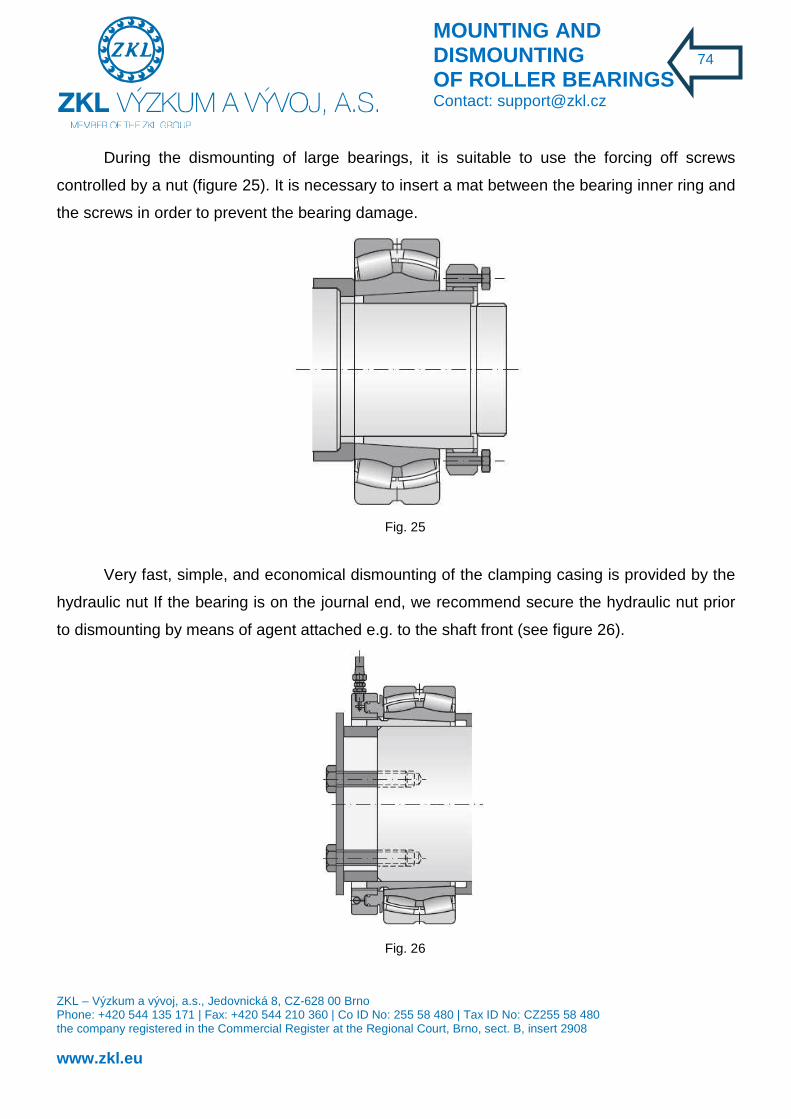
MOUNTING AND DISMOUNTING OF ROLLER BEARINGS Contact: [email protected]
ZKL – Výzkum a vývoj, a.s., Jedovnická 8, CZ-628 00 Brno Phone: +420 544 135 171 | Fax: +420 544 210 360 | Co ID No: 255 58 480 | Tax ID No: CZ255 58 480 the company registered in the Commercial Register at the Regional Court, Brno, sect. B, insert 2908 www.zkl.eu
74
During the dismounting of large bearings, it is suitable to use the forcing off screws
controlled by a nut (figure 25). It is necessary to insert a mat between the bearing inner ring and
the screws in order to prevent the bearing damage.
Fig. 25
Very fast, simple, and economical dismounting of the clamping casing is provided by the
hydraulic nut If the bearing is on the journal end, we recommend secure the hydraulic nut prior
to dismounting by means of agent attached e.g. to the shaft front (see figure 26).
Fig. 26

MOUNTING AND DISMOUNTING OF ROLLER BEARINGS Contact: [email protected]
ZKL – Výzkum a vývoj, a.s., Jedovnická 8, CZ-628 00 Brno Phone: +420 544 135 171 | Fax: +420 544 210 360 | Co ID No: 255 58 480 | Tax ID No: CZ255 58 480 the company registered in the Commercial Register at the Regional Court, Brno, sect. B, insert 2908 www.zkl.eu
75
Large clamping cases usually include channel grooves for pressure oil. Oil is introduced
directly by the clamping nut between the shaft and casing, and between the casing and bearing
(figure 27). The contact surfaces can mutually shift after pressurizing without the risk of
damage. Required pressure is reached by oil injectors. The dismounting includes oil with
viscosity 1000 mm2 / s at 200C.
Fig. 27
Hydraulic nut used with a thrust collar for
dismounting the tapered sleeve
Hydraulic nut used for dismounting the
removable tapered-sleeve adapter

MOUNTING AND DISMOUNTING OF ROLLER BEARINGS Contact: [email protected]
ZKL – Výzkum a vývoj, a.s., Jedovnická 8, CZ-628 00 Brno Phone: +420 544 135 171 | Fax: +420 544 210 360 | Co ID No: 255 58 480 | Tax ID No: CZ255 58 480 the company registered in the Commercial Register at the Regional Court, Brno, sect. B, insert 2908 www.zkl.eu
76
6. SHAFT AXIAL ALIGNMENT
Shaft axial misalignment often causes problems which lead to shut downs of rotating
machines in up to 50 % of the cases. Therefore, professional alignment of shafts is a very
effective method of preventive maintenance.
Shaft alignment leads to:
- Premature wear of bearings, seals, and shafts
- High bearing and coupling temperature
- Excessive vibrations
- Loosening of anchor bolts
- Higher consumption of energy
Shaft misalignment results in higher operating and maintenance costs and lower machine
reliability.
Research done by one of the world´s leading repair shops of rotating machines showed
that only 7 % out of 160 randomly chosen machines were aligned within acceptable tolerances.
Shaft misalignment can cause higher load on the bearings and, consequently, reduction of
bearing life.
Shaft misalignment causes a reaction force in the bearings of the driving and driven unit.
A 20 % load increase caused by axial misalignment reduces the calculated durability by up to
50 %.
Furthermore, bearing misalignment can cause higher vibrations, greater noise, and higher
energy consumption.
We distinguish two basic types of axial misalignment - parallel and angular
misalignment. In practice, these two types are always combined.
One of the definitions of axial alignment reads:
"... if the machine is working under normal operating conditions, the axes of roation of both
shafts should pass through the point where the power is transmitted from one shaft to the

MOUNTING AND DISMOUNTING OF ROLLER BEARINGS Contact: [email protected]
ZKL – Výzkum a vývoj, a.s., Jedovnická 8, CZ-628 00 Brno Phone: +420 544 135 171 | Fax: +420 544 210 360 | Co ID No: 255 58 480 | Tax ID No: CZ255 58 480 the company registered in the Commercial Register at the Regional Court, Brno, sect. B, insert 2908 www.zkl.eu
77
other". Similar to other definitions, there are exceptions to this one. Certain types of clutches
such as jaw clutches, or cardan shafts require a certain defined amount of misalignment
because of quality lubrication.
The mutual position of the machines, or their (mis)alignment, is defined by four
parameters:
- vertical offset
- horizontal offfset
- vertical angularity
- horizontal angularity.
Offset means the distance between two axes of rotation at a given point, most often in
the clutch plane.
Angularity means the angle between the axes of rotation.
Both of these values, in the vertical and horizontal directions (i.e. 4 paramters altogether)
define coaxial alignment.

MOUNTING AND DISMOUNTING OF ROLLER BEARINGS Contact: [email protected]
ZKL – Výzkum a vývoj, a.s., Jedovnická 8, CZ-628 00 Brno Phone: +420 544 135 171 | Fax: +420 544 210 360 | Co ID No: 255 58 480 | Tax ID No: CZ255 58 480 the company registered in the Commercial Register at the Regional Court, Brno, sect. B, insert 2908 www.zkl.eu
78
By coaxial alignment we mean setting two machine units so that the shaft axes of the two
machines are in a line.
If the machine is not supported on its base uniformly, we refer to this as a „loose foot“.
There is a basic rule: if the value exceeds 0.05 mm, the base must be levelled with supports, or
by further finish.
The loose foot arises from an imperfect contact between the machine foot and the base.
This may be caused by an uneven base, poorly finished machine foot, settling of the subsoil,
temperature deformation of the foundations or frame, wrong wedging of the machine foots
during machine alignment, twisted machine construction, as a result of impact for instance, etc.
There are two basic types of the loose foot – parallel loose foot and inclined loose foot. A
parallel loose foot means that, with a loose anchor bolt, there is no contact between the
machine and the machine base. By an inclined loose foot we mean a situation, where the
machine foot, with a loose anchor bolt, is only in partial contact with the base. A loose foot
causes a change in the machine position after tightening the anchor bolts, and therefore, a
change in its alignment with respect to the other machine, often in a totally unpredictable way.
This can also cause a deformation of the machine shell. A loose foot must be eliminated prior to

MOUNTING AND DISMOUNTING OF ROLLER BEARINGS Contact: [email protected]
ZKL – Výzkum a vývoj, a.s., Jedovnická 8, CZ-628 00 Brno Phone: +420 544 135 171 | Fax: +420 544 210 360 | Co ID No: 255 58 480 | Tax ID No: CZ255 58 480 the company registered in the Commercial Register at the Regional Court, Brno, sect. B, insert 2908 www.zkl.eu
79
the machine alignment, otherwise we are faced with the almost impossible task of aligning the
unalignable. There are several ways of eliminating the loose foot:
- repairing the machine base
- new machining of the machine foots, or their other modification
- wedging the loose foot with support plates.
Wedging the loose foot with support plates is simpler for the parallel loose foot, where it
suffices to use support plates of the right thickness; it is less simple for the inclined loose foot,
where a suitable wedge must either be made from standard support plates, or a wedge is made
to measure, e. g. using peel support plates.
All laser alignment devices feature as a standard equipment the loose foot inspection
function, which allows fast and simple loose foot detection and elimination. Also important is to
check the correct centering of the anchor bolts in the holes so that they allow horizontal
movement during the alignment process. The distance between the halves of the clutch must be
observed according to the manufacturer´s instructions.
Modern devices for checking and setting shaft alignment are based on the laser beam.

MOUNTING AND DISMOUNTING OF ROLLER BEARINGS Contact: [email protected]
ZKL – Výzkum a vývoj, a.s., Jedovnická 8, CZ-628 00 Brno Phone: +420 544 135 171 | Fax: +420 544 210 360 | Co ID No: 255 58 480 | Tax ID No: CZ255 58 480 the company registered in the Commercial Register at the Regional Court, Brno, sect. B, insert 2908 www.zkl.eu
80
Since axial misalignment is responsible for about 50 % of all shut-downs of rotating
machines, high precision axial alignment is essential.
The introduction of shaft alignment operations to key machines will produce cost savings,
bearing life extension, and improve side effects such as reduction of vibrations, noise, and
electric energy consumption.
7. BEARING LUBRICATION
From the design perspective, special attention must be paid to the bearing from the
lubricating system and sealing points of view.
When using plastic lubricants, regular re-lubricating must be ensured. Oil should be used
where plastic lubricant cannot be used because of the operating revolutions and temperatures,
and also where bearings are fitted in a space where other parts such as gear wheels in a
gearbox are lubricated with oil
Whether oil lubrication should be used (level, circulation-system, splash, oil-mist
lubrication), depends on the running conditions and the lubricating system of the piece of
machinery in question. The design solution must be such that the bearings have a sufficient
amount of oil not only during normal operation, but also during the machine start. Excessive
amount of oil increases its temperature.
7.1 Lubrication with plastic lubricants
Most stocks under common operating conditions use plastic lubricants. Approximately 90% of
all bearings is lubricated with plastic lubricants. It represents the advantages to the oil
lubrication. The plastic lubricants advantages are based on better lubrication position in the
stock, in the sealing against the penetration of contamination and water, and in particular in
simple bearing maintenance.

MOUNTING AND DISMOUNTING OF ROLLER BEARINGS Contact: [email protected]
ZKL – Výzkum a vývoj, a.s., Jedovnická 8, CZ-628 00 Brno Phone: +420 544 135 171 | Fax: +420 544 210 360 | Co ID No: 255 58 480 | Tax ID No: CZ255 58 480 the company registered in the Commercial Register at the Regional Court, Brno, sect. B, insert 2908 www.zkl.eu
81
The primary task of the solid lubricant in the roller bearing is the division of all parts moving
against each other by minimizing friction, preventing the wear and tear or its is maintained at the
lowest level. Solid lubricants optimally designed for the specified operation can form fully
bearing lubrication coating. If the surfaces are divided in such way, it is called “physical
lubrication”.
Three basic lubrication states are recognized:
• Limit lubrication,
• Partial lubrication,
• Full lubrication.
The limit lubrication – if the load is transferred by the surface contact, adverse lubrication
may result in extreme wear and tear and premature bearing failure. It is prevented by using the
plastic lubricants for high pressures and loads, with respective EP “extreme pressures”
additives and the protection against wear and tear or also solid lubricants additives. The
protective effects also result from the sandwich lubrication, i.e. the surface coating plus
lubrication by means of the plastic lubricant.
Partial greasing – load between the surfaces is transformed partially by means of the
created oil coating, and touching tops of the rough surfaces. The adequate additives are added
in order to prevent increased abrasion.
Full lubrication – full greasing is an ideal state when the surfaces are completely
separated by the bearing lubrication coating. It is possible to reach extremely low friction
depending on low inner lubricant friction.
The friction moment, i.e. the friction coefficient depends on the load, lubrication state, and
the bearing revolutions.
During the first assembly, the inner bearing space should be filled with lubricant only to
one half to two thirds, if the revolutions are lower than 50 % of the bearing critical revolutions,
and to one third to one half, if the revolutions are higher than 50 % of the bearing critical
revolutions. Where possible, we recommend lubricating bearings after assembly, in order to
prevent contamination or other damage caused to the lubricant during assembly.

MOUNTING AND DISMOUNTING OF ROLLER BEARINGS Contact: [email protected]
ZKL – Výzkum a vývoj, a.s., Jedovnická 8, CZ-628 00 Brno Phone: +420 544 135 171 | Fax: +420 544 210 360 | Co ID No: 255 58 480 | Tax ID No: CZ255 58 480 the company registered in the Commercial Register at the Regional Court, Brno, sect. B, insert 2908 www.zkl.eu
82
A graph for determining the free space in the bearing
Bearing type Curve
Ball bearings 618 klec T 8 - 9 618 klec M 9 160 7 60 6 62 4 63 2 - 3 64 1
Angular-contact ball bearings 70 6 72B 4 73B 2 - 3
Tapered roller bearings 302 3 - 4 303 2 313 2 320 6 322 3 - 4 323 1 - 2 329 7 - 8 330 5 331 4 332 4
Cylindrical roller bearings NU10 7 NU2 5 NU22 4 NU23 2 NU3 3 NU4 2 NN30K 5 NNU49 7
Spherical-roller bearings 213 3 222 4 223 2 230 6 231 4 232 3 - 4 239 8 240 5 241 3

MOUNTING AND DISMOUNTING OF ROLLER BEARINGS Contact: [email protected]
ZKL – Výzkum a vývoj, a.s., Jedovnická 8, CZ-628 00 Brno Phone: +420 544 135 171 | Fax: +420 544 210 360 | Co ID No: 255 58 480 | Tax ID No: CZ255 58 480 the company registered in the Commercial Register at the Regional Court, Brno, sect. B, insert 2908 www.zkl.eu
83
For most thrust bearing applications, running-in is not necessary. The reason is that the
required revolution factor is met anyway. Running-in is therefore required for high-precision
bearings designed for high revolutions. By running- in a thrust bearing with plastic lubricant, the
revolution factor can be substantially increased. During running-in, the hardener structure is
adjusted so that oil separation, and therefore oil elimination, occurs ideally in the direction of the
bearing raceways. In this way, there is only the necessary amount of lubricant in the contact
zone. Then plastic lubricant as such is not captured by the rollers or cage.
The selection of appropriate plastic lubricant as regards large selection which is currently
available is performed in few several steps and by means of the most important criteria. The
more data available to more accurate the lubricant selection.
Criteria for selecting plastic lubricant (PM):
• Operating temperature,
• Specification of minimum required viscosity based on the base oil,
• Revolution factor,
• Load index C/P.
Plastic lubricant looses its greasing properties after some time. The main factors affecting
the plastic lubricant service life:
• Lubricant quality
• Bearing size,
• Operating revolutions,
• Operating temperature,
• Operating environment.

MOUNTING AND DISMOUNTING OF ROLLER BEARINGS Contact: [email protected]
ZKL – Výzkum a vývoj, a.s., Jedovnická 8, CZ-628 00 Brno Phone: +420 544 135 171 | Fax: +420 544 210 360 | Co ID No: 255 58 480 | Tax ID No: CZ255 58 480 the company registered in the Commercial Register at the Regional Court, Brno, sect. B, insert 2908 www.zkl.eu
84
It is therefore necessary to regularly lubricate the bearings. The lubrication automatic period
is a period when the plastic lubricant keeps the required properties. After the period passes, the
bearing must be re-lubricate, and the old lubricant must be completely removed from the
bearing area. The recommended duration of the lubrication automatic period tf can be read from
the scheme below, which specifies the value depending on the operating revolutions n, and on
the bearing diameter d.
The scheme applies for the operation conditions:
• The bearing load does not exceed 15% of basic dynamic load capacity,
• Plastic lubricant of common quality is used,
• External bearing ring operating temperature is max. 70 °C,
• The bearing is placed on horizontal shaft.
If the operating temperature exceeds 70 °C, the lubrication automatic period is reduced, for
each 15 °C, by which temperature exceeds 70 °C, to one half. At temperature below 40 °C, it is
possible to increase the automatic lubrication up to the double. We recommend reducing tf for
the bearings placed on the vertical shafts as per the scheme to one half.

MOUNTING AND DISMOUNTING OF ROLLER BEARINGS Contact: [email protected]
ZKL – Výzkum a vývoj, a.s., Jedovnická 8, CZ-628 00 Brno Phone: +420 544 135 171 | Fax: +420 544 210 360 | Co ID No: 255 58 480 | Tax ID No: CZ255 58 480 the company registered in the Commercial Register at the Regional Court, Brno, sect. B, insert 2908 www.zkl.eu
85
Graph for automatic lubrication with plastic lubricants

MOUNTING AND DISMOUNTING OF ROLLER BEARINGS Contact: [email protected]
ZKL – Výzkum a vývoj, a.s., Jedovnická 8, CZ-628 00 Brno Phone: +420 544 135 171 | Fax: +420 544 210 360 | Co ID No: 255 58 480 | Tax ID No: CZ255 58 480 the company registered in the Commercial Register at the Regional Court, Brno, sect. B, insert 2908 www.zkl.eu
86
Graph for automatic lubrication with plastic lubricants
For small, in particular single row ball bearings, the lubrication automatic periods are
multiply linger than the bearing service life, the bearings therefore do not require lubrication.
The reason above indicate it is beneficial to use the bearings in design with the cover
sheet metal or with sealing on both sides, filled by the manufacturer with plastic lubricant for the
full service life. For some frequencies, the automatic lubrication period is outside the graph
curves, which means the permitted limit for greasing with plastic lubricants is exceeded. In
these cases, we recommend resolving the stock construction for oil lubrication.

MOUNTING AND DISMOUNTING OF ROLLER BEARINGS Contact: [email protected]
ZKL – Výzkum a vývoj, a.s., Jedovnická 8, CZ-628 00 Brno Phone: +420 544 135 171 | Fax: +420 544 210 360 | Co ID No: 255 58 480 | Tax ID No: CZ255 58 480 the company registered in the Commercial Register at the Regional Court, Brno, sect. B, insert 2908 www.zkl.eu
87
Regenerating the plastic lubrication filling is recommended always with the automatic
lubrication interval exceeding 6 months. The application of plastic lubricants for high
performance can extend the automatic lubrication period. For further information, contact ZKL
technical-consulting services.
The amount of Q lubricant for final bearing lubrication is specified according to the
instructions of the device manufacturer where the bearing is assembled, or as per the formula
Q = 0,005 * D * B
where Q ... Lubricant amount [g]
D ... Bearing outer diameter [mm]
B ... Bearing width [mm]
Plastic lubricant is supplied to the bearing ideally by the lubrication press. For bearing
design W33 it is most suitable (if enabled by the construction) to introduce plastic lubricant
through the holes in external ring. If the bearing operates at quite high revolutions, i.e. it
requires frequent additional lubrication, there is a hazard of excessive lubricant accumulation in
the bearing area. This lubricant must be removed after some period by means of the lubricant
spray removal forming a part of the stock structure. New spherical-roller bearings operating at
high revolutions using the lubricant spray removal must be sufficiently lubricated at the
operation commencement. After one hour and then again after 24 hours from starting the new
bearings, the triple amount of common lubricant should be added.
Factors reducing the final lubrication period: High vibrations, vertical shaft (automatic
lubrication period must be reduced to one half, and it is necessary to use sealing and covers
preventing the lubricant leak), lubricant contamination.
Important notice: Automatic lubrication uses the same type of plastic lubricant as used
before. Never mix various plastic lubricants, unless you are sure they are mutually compatible.

MOUNTING AND DISMOUNTING OF ROLLER BEARINGS Contact: [email protected]
ZKL – Výzkum a vývoj, a.s., Jedovnická 8, CZ-628 00 Brno Phone: +420 544 135 171 | Fax: +420 544 210 360 | Co ID No: 255 58 480 | Tax ID No: CZ255 58 480 the company registered in the Commercial Register at the Regional Court, Brno, sect. B, insert 2908 www.zkl.eu
88
Since in practise, the mixing of plastic lubricants cannot be completely avoided, it is possible to
use the mixtures below, without significant consequences:
• Plastic lubricants with the same thickening agent
• Lithium/ calcite plastic lubricants,
• Calcite / bentonite plastic lubricants,
Unsuitable mixtures of plastic lubricants:
• Sodium / lithium,
• Sodium / calcite,
• Sodium / aluminium,
• Sodium / bentonite,
• Aluminium / bentonite,
During mixing of the above lubricants, the change of the structure may occur resulting in
strong softening of the plastic lubricant. If different type of plastic lubricant should be used, it is
necessary to perform the automatic lubrication with large amount of lubricant (rinsing with
plastic greasing agent), if enabled by the stock construction. Potential further lubrication should
be completed for shorter period. The review of plastic lubricants is available in table 8.

MOUNTING AND DISMOUNTING OF ROLLER BEARINGS Contact: [email protected]
ZKL – Výzkum a vývoj, a.s., Jedovnická 8, CZ-628 00 Brno Phone: +420 544 135 171 | Fax: +420 544 210 360 | Co ID No: 255 58 480 | Tax ID No: CZ255 58 480 the company registered in the Commercial Register at the Regional Court, Brno, sect. B, insert 2908 www.zkl.eu
89
Table 8. Review of plastic lubricants
Grease characteristics for roller bearings
Grease type Characteristics
Thickening agent Base oil Heat range of use [°C]
Water resistance
Application
Lithium soap mineral -20 to 130 resistant multi-purpose lubricant
calcium soap mineral -20 to 50 highly
resistant good sealing effect against water
sodium soap mineral -20 to 100 non-resistant emulsifies with water aluminium soap mineral -20 to 70 resistant good sealing effect against water lithium complex soap mineral -20 to 150 resistant multi-purpose lubricant
calcium complex soap mineral -30 to 130 highly
resistant multi-purpose high temperature, high-load lubricant
sodium complex soap mineral -20 to 130 resistant suitable for high temperatures, high loads
aluminium complex soap
mineral -20 to 150 resistant suitable for high temperatures, high loads
barium complex soap mineral -30 to 140 resistant suitable for high temperatures, high loads
bentonite mineral -20 to 150 resistant suitable for high temperatures and low speeds
polycarbamide mineral -20 to 160 resistant suitable for high temperatures and medium speeds
lithium soap silicone -40 to 170 highly
resistant suitable for wide temperature ranges and medium rotational speeds
barium complex soap ester -60 to 140 resistant suitable for high temperatures and high speeds
7.2 Oil lubrication
The bearing oil lubrication is used in the cases below:
• Automatic lubrication intervals with plastic lubricants are too short:
• The operating temperature is so high, it is not suitable to use plastic lubricant,
• The whole device is oil lubricated (e.g. gearboxes).
The spherical roller bearings use the oil bath lubrication, and the oil level reaches usually
up to the central height of the lowest rolling body in the bearing, and for oil circulation

MOUNTING AND DISMOUNTING OF ROLLER BEARINGS Contact: [email protected]
ZKL – Výzkum a vývoj, a.s., Jedovnická 8, CZ-628 00 Brno Phone: +420 544 135 171 | Fax: +420 544 210 360 | Co ID No: 255 58 480 | Tax ID No: CZ255 58 480 the company registered in the Commercial Register at the Regional Court, Brno, sect. B, insert 2908 www.zkl.eu
90
lubrication. The lubrication of roller bearings usually includes the use of mineral oil with good
chemical stability. Suitable relative viscosity of mineral oil ν1, is specified in the graph depending
on the bearing medium diameter:
ds = (D + d) / 2
where ds ... Bearing central diameter [mm]
D ... Bearing outer diameter [mm]
d ... Bore diameter [mm]
If the operating temperature t is known (or can be found), we can use the graph to
specify the operating viscosity v at internationally standardized comparable temperature 40 °C
which is required for the viscosity ratio calculation
k = ν / ν1,
where to ... Viscosity ratio
ν ... Operating viscosity [mm2s']
ν1 ... related viscosity [mm2s']
If k is lower than 1, it is recommended using oil with EP additives preventing the melting
of metal parts in the contact location at local temperature increase. If k drops under value 0.4
the use of oil with EP additives is necessary.

MOUNTING AND DISMOUNTING OF ROLLER BEARINGS Contact: [email protected]
ZKL – Výzkum a vývoj, a.s., Jedovnická 8, CZ-628 00 Brno Phone: +420 544 135 171 | Fax: +420 544 210 360 | Co ID No: 255 58 480 | Tax ID No: CZ255 58 480 the company registered in the Commercial Register at the Regional Court, Brno, sect. B, insert 2908 www.zkl.eu
91
Graph for selecting cinematic viscosity of the lubricant at 40 °C

MOUNTING AND DISMOUNTING OF ROLLER BEARINGS Contact: [email protected]
ZKL – Výzkum a vývoj, a.s., Jedovnická 8, CZ-628 00 Brno Phone: +420 544 135 171 | Fax: +420 544 210 360 | Co ID No: 255 58 480 | Tax ID No: CZ255 58 480 the company registered in the Commercial Register at the Regional Court, Brno, sect. B, insert 2908 www.zkl.eu
92
Graph for specifying the operating viscosity of the lubricant

MOUNTING AND DISMOUNTING OF ROLLER BEARINGS Contact: [email protected]
ZKL – Výzkum a vývoj, a.s., Jedovnická 8, CZ-628 00 Brno Phone: +420 544 135 171 | Fax: +420 544 210 360 | Co ID No: 255 58 480 | Tax ID No: CZ255 58 480 the company registered in the Commercial Register at the Regional Court, Brno, sect. B, insert 2908 www.zkl.eu
93
8. BEARING MAINTENANCE
Most correctly selected and mounted bearings require hardly any maintenance, except
regular re-lubricating.
Monitoring the reliability of operation is limited to temperature control, occasional bearing
tapping, and vibrodiagnostic monitoring, if it is available.
Some errors in the bearing operation become evident by an increase or fluctuation of
vibrations, temperature, and noise values. In this case we recommend informing the
manufacturer about these parameter values.
Bearings in a good operating condition give out a fine buzz. Unusual noise indicates that
the bearing is in a poor operating condition.
A bearing which was found defective during operation must be dismounted so that the
root cause may be discovered and eliminated. Further, steps must be taken to prevent
premature damage to the spare bearing. This is especially important in the case of large
bearings and key machines.
Monitoring the operating condition is becoming increasingly useful in preventive
maintenance. Early detection of damage signs allows to replace the bearing during planned
maintenance, which prevents unplanned shut-downs caused by bearing emergencies.
8.1 Machine maintenance
The role of maintenance is not to repair damaged machines but to prevent their damage
but not just that. We want our machines to work efficiently, reliably and safely. The objectives of
maintenance can be therefore expressed in three interconnected requirements:

MOUNTING AND DISMOUNTING OF ROLLER BEARINGS Contact: [email protected]
ZKL – Výzkum a vývoj, a.s., Jedovnická 8, CZ-628 00 Brno Phone: +420 544 135 171 | Fax: +420 544 210 360 | Co ID No: 255 58 480 | Tax ID No: CZ255 58 480 the company registered in the Commercial Register at the Regional Court, Brno, sect. B, insert 2908 www.zkl.eu
94
1. achieve maximum productivity:
� Ensure satisfactory and continuous operation of the machine throughout its
designed service life, or even longer.
� Achieve higher machine sustainability with minimum shutdowns for maintenance
and repairs
� Continuously improving the manufacturing process.
2. Optimise machine efficiency – Calmly, economically running machines cost less and
produce products of higher quality.
3. Ensure safety of operation.
8.2 Types of maintenance
During technological development several types of maintenance had developed the
application of which depends on a number of circumstances that need to be taken into account.
Basic maintenance tasks are stated in the above paragraph. When evaluating these, apart from
operational safety, one has to consider costs as well. Therefore, small and backed up plants still
utilize the maintenance-free system – i.e. operation until failure. This type of maintenance is
called reactive.
More expensive plants, operation of which is more expensive, have recently accustomed
to a maintenance method consisting of periodical inspections, revision or repairs – i.e.
preventive maintenance. An example of it can be cars with a service book according to which
certain service actions are performed in certain time intervals, or by driven distance. The goal is
to avoid machine failure. The time until repair is calculated according to the frequency of similar
appliances (frequency of failures is expressed by the so-called mean time to failure). This is
kind of a weakness of the method since it is difficult to estimate the time between the repairs -
some appliances fail earlier, some are inspected or repaired “in vain” (they were OK). Mostly
due to the effort to avoid unexpected failures, and also due to the effort to optimise maintenance
costs which in a medium size enterprise represent about 1/3 of all costs, two additional
aforementioned types of maintenance has been developing:

MOUNTING AND DISMOUNTING OF ROLLER BEARINGS Contact: [email protected]
ZKL – Výzkum a vývoj, a.s., Jedovnická 8, CZ-628 00 Brno Phone: +420 544 135 171 | Fax: +420 544 210 360 | Co ID No: 255 58 480 | Tax ID No: CZ255 58 480 the company registered in the Commercial Register at the Regional Court, Brno, sect. B, insert 2908 www.zkl.eu
95
Predictive maintenance – Machine is not repaired in pre-defined intervals but only if the
condition of it requires so. This certainly requires knowing this condition, and therefore it has to
be watched during operation (monitoring and diagnostics). Such approach helps us prevent
unplanned failures and shutdowns. The key idea is the right information at the right time. If you
know which part of the plant requires replacement or repair, spare parts can be ordered in
advance, staff can be provided for, etc., and shutdown can be performed when it is convenient.
A planned shutdown is shorter and less expensive than a shutdown forced by an appliance
failure, or even by an accident. Other advantages of predictive maintenance are longer life of
the appliance, enhanced safety, less accidents with negative consequences for living
environment, optimisation of spare parts management, etc.
Proactive maintenance - on top of the previously described management type includes
also a solution of the root cause of deteriorated condition. Corrective actions are not focused on
current failure symptoms (e.g. damaged bearing) but the key idea is to find out and remove the
root cause of that failure (e.g. damage of bearing occurs as a result of improper machine
positioning).
In predictive and proactive maintenance you thus need to examine the current condition
of the machine. The maintenance process can be divided in five stages:
1. finding out initial condition – involves comprehensive measurement of the machine at
the time when it is OK, and the so-called basic, reference values are stated for
subsequent comparison.
2. monitoring – spots are defined on the machines where vibrations are measured in
regular intervals, mostly total values of vibrations. This activity can be carried out by a
trained worker without any knowledge of diagnostics.
3. detection – data obtained in monitoring are evaluated in a simple quantitative manner.
Alarm limits are defined for every quantity measured. If a quantity exceeds the
programmed alarm limit, it is a notification of a problem.
4. analysis (own diagnostics ) – detection of a problem is followed by detailed
measurement and analysis (trend evaluation, FFT analysis, phase analysis, etc.) which
facilitates a clearer view to the problem and its root cause.
5. recommendation – once the root cause of the problem is found, economically
acceptable corrective measures can be recommended and adopted.

MOUNTING AND DISMOUNTING OF ROLLER BEARINGS Contact: [email protected]
ZKL – Výzkum a vývoj, a.s., Jedovnická 8, CZ-628 00 Brno Phone: +420 544 135 171 | Fax: +420 544 210 360 | Co ID No: 255 58 480 | Tax ID No: CZ255 58 480 the company registered in the Commercial Register at the Regional Court, Brno, sect. B, insert 2908 www.zkl.eu
96
8.3 Diagnostics
By diagnostics, we usually mean monitoring and evaluating the state of the
machine during operation. In practice, however, other parameters must also be used for
monitoring the state of the machine. Most procedures are described by international ISO
standards. The different types of diagnostics by the type of parameters analyzed are as
follows:
� Operational diagnostics
Attention is paid primarily to bearings, because they represent an essential part of all
machines with rotating parts.
Bearings working in important parts of machinery or in demanding operating conditions
should be frequently inspected. At present, a whole number of systems and devices for
monitoring the bearing condition are available.
In practice, however, not all machines and their functionality can be monitored by
sophisticated modern devices. In such cases, the machine operators, or maintenance workers
must keep watching for any signs of problems in the bearing such as noise, rising temperature,
or vibrations. This is mainly done by listening, touch, or vision.
By listening we usually find out whether the machine run is regular or irregular. An
experienced worker is able not only to use a stethoscope to detect unusual sounds, but also to
determine the corresponding part of the machine. Bearings in good operating condition give out
a fine buzz. Sounds like grinding, screeching, or other unusual sounds usually indicate that the
bearing is in a poor operating condition.
Screeching or whistling may be caused by insufficient lubrication. Small bearing
clearance may manifest itself by a metal noise. Damage to the ring caused by impact during
assembly, or by imprints and grooves in raceways cause a noise which varies with bearing
revolutions. Intermittent noise may indicate damage to a rollerbody. The noise comes from
rolling over a damages surface. Dirt in the bearing causes a grinding noise.

MOUNTING AND DISMOUNTING OF ROLLER BEARINGS Contact: [email protected]
ZKL – Výzkum a vývoj, a.s., Jedovnická 8, CZ-628 00 Brno Phone: +420 544 135 171 | Fax: +420 544 210 360 | Co ID No: 255 58 480 | Tax ID No: CZ255 58 480 the company registered in the Commercial Register at the Regional Court, Brno, sect. B, insert 2908 www.zkl.eu
97
Although damage to the bearing can be detected by listening, it is usually so serious that
the bearing must be replaced immediately. For this reason, it is better to use certain electronic
devices for monitoring the bearing condition.
It has been proved that these modern devices provide a much safer and more accurate
way of estimating the bearing condition than some of the procedures used formerly, such as
pressing one end of a screwdriver against the bearing body and holding and ear to the other
end.
Touching can be used to detect high temperatures, which often indicate an unusual
bearing condition. These may have a negative effect on the lubricant in the bearing. Sometimes
overheating can also be related to the lubricant present in the bearing. If the bearing works in
temperatures higher than 125º C over a longer period of time, its durability may be reduced. The
high temperature may be caused by insufficient, or on the contrary excessive amount of
lubricant, contaminated lubricant, damage to the bearing, small clearance, clamping and
excessive friction of the seals.
Therefore, it is necessary to frequently check the bearing temperature as well as the
temperature of other important parts. Any change of temperature may be a sign of defect, if the
running conditions have not changed.
The bearing temperature can be regularly and reliably checked by contact thermometer.
Any change of temperature may be a sign of defect, if the running conditions have not changed.
Some digital thermometers feature colour signalling indicating normal operation, increased
temperatures, and critical temperature when the machine must be turned off. Such temperature
sensors with the signalling should be applied to bearings in critical locations, where an
emergency might cause the machine shut-down.
Let us emphasize that after lubricating or re-lubricating the temperature usually increases
for a period of one or two days.
Visual inspection can be used for inspecting the bearing sealing so as to prevent hot or
agressive liquids and gases from entering the bearing along the shaft. Maintain the pre-set rings

MOUNTING AND DISMOUNTING OF ROLLER BEARINGS Contact: [email protected]
ZKL – Výzkum a vývoj, a.s., Jedovnická 8, CZ-628 00 Brno Phone: +420 544 135 171 | Fax: +420 544 210 360 | Co ID No: 255 58 480 | Tax ID No: CZ255 58 480 the company registered in the Commercial Register at the Regional Court, Brno, sect. B, insert 2908 www.zkl.eu
98
and labyrinth packings filled with plastic lubricants to ensure maximum protection. Replace felt
and rubber seals as soon as possible.
The seal not only prevents dirt from penetrating into the bearing, but also prevents
lubricant from leaking. If lubricant leaks around the seal, check immediately if the seal is not
worn-out, defective, or if the plugs are not loose. Lubricant leakage can also be caused by
untightness of insufficiently clamped contact surfaces in the division plane of the bearing body
or released oil leakage when plastic lubricant has been destroyed as a result of excessive
mechanical stress, i.e. by over-lubrication.
The lubricant itself must also be carefully watched. Different or dark colour usually
indicates that the lubricant is contaminated.
There are a whole number of ways of monitoring the bearing operating condition, which
can help to find out whether the bearing is likely to break down, and avoid costly machine shut-
downs.
Data provided by diagnostic devices can assist users in preventing unplanned shut-
downs. The devices regularly provide instant reports on the operating condition of the bearing,
and based on the evolution trend, the bearing can be replaced during planned shut-downs. This
saves time, costs and makes it possible to purchase replacement bearings well in advance.
Monitoring the operating condition is an aggregate term denoting the monitoring of the
machinery condition using devices.
Operational diagnostics utilizes all available measured service parameters that allow
evaluation of the machine condition in run. For new appliances often online systems with big
databases are used and potential software for their analysis. For less complicated machine
units one periodically records parameters and may carry out tests in run, in order to verify
correct function. The issue is dealt with in ISO 17359. Table 1 is taken over from the
aforementioned standard and demonstrates how individual service parameters are associated
with failures in the machine. Majority of failures in rotary machines usually manifest in change of
size and spectral content of vibrations.

MOUNTING AND DISMOUNTING OF ROLLER BEARINGS Contact: [email protected]
ZKL – Výzkum a vývoj, a.s., Jedovnická 8, CZ-628 00 Brno Phone: +420 544 135 171 | Fax: +420 544 210 360 | Co ID No: 255 58 480 | Tax ID No: CZ255 58 480 the company registered in the Commercial Register at the Regional Court, Brno, sect. B, insert 2908 www.zkl.eu
99
Table 1 Example of monitoring service parameters according to ISO 17359
Machine type: Pump
Symptom or parameter change
Failure Leak
of liquid
Measurement of lengths
Power output
Pressure or
vacuum
Revolutions
Vibrations Tempera
ture Stoptime
Oil contamin
ation
Oil leak
Damaged impeller
● ● ● ● ● ● ● ●
Damaged plugs
● ● ● ● ●
Eccentric impeller
● ● ● ● ● ●
Damaged bearing
● ● ● ● ● ● ● ●
Worn bearing ● ● ● ● ●
Improper assembly
●
Imbalance ●
Misalignment ● ●
* If a failure occurs, indicated symptom or parameter change may occur.
� Tribodiagnostics
Fulfils three basic tasks:
� Monitoring the state of lubricant – The state of lubricant may deteriorate for various
reasons (oxidation, penetration of water or other substances, etc.).
� Analysis of impurities and abrasion particles (ferrography) – Based on material and
shape of particles that occur in lubricant a place is determined where the machine
usually gets damaged.
Tribodiagnostics (TD), as a part of maintenance, is based on regularly sampling
lubricants, essentially lubricating oils only, used in the monitored machines, and analyzing these
samples. This analysis can be used to determine the state of the oil itself and also the state of
the monitored machine. Lubricating oil serves in this case as a medium carrying along particles
originating from the wear of the lubricated parts of the monitored machine. Analysis of these
parts yields important information on the processes happening in the machine. It is important to
monitor the machine continuously in this way, and obtain trends of the volume of the particles

MOUNTING AND DISMOUNTING OF ROLLER BEARINGS Contact: [email protected]
ZKL – Výzkum a vývoj, a.s., Jedovnická 8, CZ-628 00 Brno Phone: +420 544 135 171 | Fax: +420 544 210 360 | Co ID No: 255 58 480 | Tax ID No: CZ255 58 480 the company registered in the Commercial Register at the Regional Court, Brno, sect. B, insert 2908 www.zkl.eu
100
present in the oil, because these give a sufficiently reliable information on changes occurring in
the wear regime. The second part of TD is the oil analysis which detects changes in the
chemical and physical qualities of the oil on the one hand, and contamination by foreign
substances such as water, mechanical contamination, chemical compounds, on the other hand.
Successful TD is based on a correctly taken oil sample. The sample must be truly
representative, i.e. contain all substances in the proportion in which they occur in the lubricating
system of the monitored machine. The best point for taking the sample is the run-back pipe
which takes the oil from the lubricated points to the oil reservoir. However, since it is frequently
not possible to take the sample at this point, the samples are often taken from the oil reservoir.
The sampling must be carried out during the machine run if possible, or immediately after its
stopping. The sample container must be clean and dry. An important aspect of any diagnostic
method, and therefore TD, is the rapidity of the response and accuracy of results. Regularly
taken samples are analyzed as rapidly as possible, and diagnosis is made on the basis of the
results.
Monitoring the machine condition
In this case, lubricating oil is utilized as a medium carrying, during the wear process, metal
particles produced by this wear process. Regular monitoring of specified metal concentrations
allows to foresee impending failures. For determination of metals, or elements in lubricating oils,
various methods of instrumental analysis are used. All these methods serve for determining the
monitored element concentration. For monitoring the machine condition, one must know the
materials from which the machines are made. Increased occurence of a certain element means
increased wear of a certain machine part. E.g. occurrence of copper usually signals bearing
wear, occurrence of aluminium signals piston or bearing wear etc.
Monitoring the oil condition
When monitoring the properties of lubricating oils, the values of a large number of indices are
determined, and it is not the purpose of the present manual to enumerate them all. Nowadays,
practically all lubricant types contain additives which improve some of their properties. During
operation, there is loss of additives, and when a certain minimum level is exceeded, the
lubricant loses its utility properties. Very important for the determination of additive content is

MOUNTING AND DISMOUNTING OF ROLLER BEARINGS Contact: [email protected]
ZKL – Výzkum a vývoj, a.s., Jedovnická 8, CZ-628 00 Brno Phone: +420 544 135 171 | Fax: +420 544 210 360 | Co ID No: 255 58 480 | Tax ID No: CZ255 58 480 the company registered in the Commercial Register at the Regional Court, Brno, sect. B, insert 2908 www.zkl.eu
101
infrared spectrometry, presently probably the most useful methodology for analyzing lubricants.
Computer controlled devices with Fourier transform enable a very fast and sensitive analysis of
important groups of organic compounds present in lubricants. Infrared spectrometry can also be
used for determining the products of oil aging, especially oil oxidation and oil nitration products.
By comparing the spectra of used and clean oil, oil contamination can be determined. Presence
of water and glycol, presence of fuel in the oil are some of the other possible applications of this
almost universal methodology.
Oil analysis evaluation
After analyzing a given lubricating oil sample, we obtain a set of values. This set can be
evaluated by comparing each of the specified indices with their critical values, if they are known.
In this way, we get fairly easily the answer to the question, whether the tested oil can be further
used, or whether the machine is wearing out excessively. This procedure is satisfactory for
determining the oil condition, and the general evaluation of the analysis can be considered as
reliable. The critical values for each of the indices are in most cases known. For monitoring the
machine wear, the situation is different. Monitoring the trends in the content of each element is
very useful here. The diagnostic signal is then represented not by exceeding the critical value,
but by a sudden change in the trend of the monitored content. Critical values of element content
can be reliably determined on the basis of long-term tests organized by the machine
manufacturer.
Effectiveness and usefulness of tribodiagnostics
Any lubricating oil analysis costs money. When discussing the usefulness of TD, the price of the
analysis is compared with the price of the oil fill. This is understandable, because these two
values are easily determined. However, a correctly performed TD cannot be limited to saving oil
only. As indicated above, savings can be made not only on oil, but also on machine idle time,
spare parts, (because a signal which is received in time allows to prevent an extensive failure
which requires extensive repair), and on maintenance work. Due to increased attention being
paid to environmental protection, the fact that a smaller number of oil changes and oil
manipulations reduces the danger of oil and contamination leaking into the environment, is not
negligible. An important and little emphasized advantage of TD is that it detects failures at their

MOUNTING AND DISMOUNTING OF ROLLER BEARINGS Contact: [email protected]
ZKL – Výzkum a vývoj, a.s., Jedovnická 8, CZ-628 00 Brno Phone: +420 544 135 171 | Fax: +420 544 210 360 | Co ID No: 255 58 480 | Tax ID No: CZ255 58 480 the company registered in the Commercial Register at the Regional Court, Brno, sect. B, insert 2908 www.zkl.eu
102
very beginning. If oil samples are regularly analyzed for metal content, the first deviation from
normal is usually captured (and if required, confirmed by a check sample) early enough for
effective steps to be taken well in advance.
� Thermodiagnostics
Thermodiagnostics (temperature measurement, thermovision measurement) – By means
of local or flat measurement of surface temperature places with different temperature can be
detected, and thus the cause of that increased temperature evaluated (excessive friction, high
electrical resistance, etc.). Figure 1 shows an example of themovision diagnostics application in
order to find out misalignment in clutch (if the clutch is out of line, transmitted power is inhibited
to a greater extent; the power converts to heat that heats the clutch and neighbour bearings).
The shot from thermovision camera is supplemented by a regular photograph to make clear
what appliance it is about.

MOUNTING AND DISMOUNTING OF ROLLER BEARINGS Contact: [email protected]
ZKL – Výzkum a vývoj, a.s., Jedovnická 8, CZ-628 00 Brno Phone: +420 544 135 171 | Fax: +420 544 210 360 | Co ID No: 255 58 480 | Tax ID No: CZ255 58 480 the company registered in the Commercial Register at the Regional Court, Brno, sect. B, insert 2908 www.zkl.eu
103
Figure: Example of thermovision measurement
The bearing temperature can be checked, for instance, by touch, but continuous regular
checking by permanent temperature sensors is the best. High temperature usually indicates an
unusual bearing condition. The life of bearings working at temperatures higher than 125º C over
a longer period of time can be seriously reduced. The cause of the high temperature may
consist in too little or too much lubricant, bearing damage, bearing overload, eliminated
cleareance in the bearing etc.
Vibration diagnostics
Vibrodiagnostics is the basis of predictive and proactive maintenance and enables
effective machine operation. It also represents a principal no-disassembly diagnostic method for
rolling bearings, where it is very successful in defect detection.
During monitoring vibrations using converters, it converts mechanical movement to
electric signal. The signal from the vibrations carries information on the cause of the vibrations,

MOUNTING AND DISMOUNTING OF ROLLER BEARINGS Contact: [email protected]
ZKL – Výzkum a vývoj, a.s., Jedovnická 8, CZ-628 00 Brno Phone: +420 544 135 171 | Fax: +420 544 210 360 | Co ID No: 255 58 480 | Tax ID No: CZ255 58 480 the company registered in the Commercial Register at the Regional Court, Brno, sect. B, insert 2908 www.zkl.eu
104
and by analyzing the signal with various methods, the defect can be detected in its beginning or
development.
Low-frequency vibrations (0-2 kHz) are caused by the frame vibrations or by wrong
assembly such as coaxial misalignment, imbalance, loose parts, and by rollers rolling over
damaged areas.
High frequency vibrations (2 – 50 kHz) arise each time a roller rolles over a damage spot.
This give rise to small impulses, which transmit their energy to the bearing body, which
responds by oscillating at its proper frequency and gradual damping of the oscillations in the
mechanical construction. By comparing the frequency spectra recorded during a definite time
interval, an increase in amplitude can be detected during a proper frequency peak, which may
be related to bearing damage. Very high frequencies are in the accoustic emission range, i. e.
over 50 kHz, and are caused by the rollers rolling over damaged areas and by metal-to-metal
contact. These signals can be detected by very sensitive devices such as sensors.
Another way of detecting bearing defects on the basis of vibrations is based on
determining the typical frequencies of bearing defects. Each rolling of the rollers over the
damaged area causes a peak in the signal. Repetition of peaks depends on the position of the
damaged area in the bearing (in the inner or outer ring, roller etc.), on the bearing geometry and
revolutions.
Envelope analysis is a method that uses both very high frequencies, and signal repetition
caused by bearing defects in the low-frequency range. During envelope analysis, the signal is
first carried into the filter, which lets through only high frequencies and eliminates most of the
noise caused by construction vibrations, coaxial misalignment etc. The energy decreases, but
the impulses are repeated at the same intervals, because the frequency of repeating the signal
caused by the bearing defect is not changed by filtering.
The envelope analysis can be applied to all frequencies, but is generally used in the low-
frequency range.
Monitoring the operating condition represents an effective way of predicting a failure of
the machine or it part, which means that sudden emergencies, which cause costly repairs and
uplanned interruptions of production, can be prevented. Methods and devices adequate to the
machine type should be selected.

MOUNTING AND DISMOUNTING OF ROLLER BEARINGS Contact: [email protected]
ZKL – Výzkum a vývoj, a.s., Jedovnická 8, CZ-628 00 Brno Phone: +420 544 135 171 | Fax: +420 544 210 360 | Co ID No: 255 58 480 | Tax ID No: CZ255 58 480 the company registered in the Commercial Register at the Regional Court, Brno, sect. B, insert 2908 www.zkl.eu
105
The operating condition can be regularly recorded using portable devices, and the
information sooner or later evaluated.
Machines working continuously, such as paper machines, are best protected by a device
for continuously monitoring the operating condition, supplemented with automatic alarm which
signals the attainment of a pre-set state. More important machines, such as winding machines
in head frames, can be equipped with a device for continuous monitoring of the operating
condition, which stops the machine as soon as a certain vibration level is attained.
Monitoring the operating condition in continuous regime

MOUNTING AND DISMOUNTING OF ROLLER BEARINGS Contact: [email protected]
ZKL – Výzkum a vývoj, a.s., Jedovnická 8, CZ-628 00 Brno Phone: +420 544 135 171 | Fax: +420 544 210 360 | Co ID No: 255 58 480 | Tax ID No: CZ255 58 480 the company registered in the Commercial Register at the Regional Court, Brno, sect. B, insert 2908 www.zkl.eu
106
9. OTPP
9.1 Offered services
The respective department focuses on resolving the customer related problems:
The application engineers can:
� Analyze the stock – find the problem (cooperation with the IT department)
� Propose a solution - cooperation with the construction
� Cooperation during assembly
� Provide consulting with lubrication
� Perform standard, potentially individual training for the customers

MOUNTING AND DISMOUNTING OF ROLLER BEARINGS Contact: [email protected]
ZKL – Výzkum a vývoj, a.s., Jedovnická 8, CZ-628 00 Brno Phone: +420 544 135 171 | Fax: +420 544 210 360 | Co ID No: 255 58 480 | Tax ID No: CZ255 58 480 the company registered in the Commercial Register at the Regional Court, Brno, sect. B, insert 2908 www.zkl.eu
107
10. FAILURES OF ROLLER BEARINGS
10.1 Causes of bearing emergency
Only in a small proportion of all operated bearings an emergency occurs during
operation. Most bearings have a longer life than the machines or apparatus in which they are
mounted.
A bearing emergency can have a number of causes:
- Unprofessional assembly – e. g. assembly with a large overlap, causing bearing
damage,
- Higher load than anticipated,
- Inefficient seal – penetration of dirt
- Faulty lubrication – for instance, a poorly designed lubricating system, insufficient
thickness of lubricating film
Based on the bearing inspection and the characteristic signs of damage, the cause of the
damage and emergency can in most cases be determined and eliminated.
Only in 10 % of all bearing emergencies, the fatigue damage of the bearing functional
surfaces results from long-term operation, 43 % of the bearings had an emergency because of
insufficient lubrication, and in nearly one half of all bearings, the bearing emergency was caused by
faulty assembly or penetration of foreign matter or dirt into the bearing.
Occurrence of bearing failures

MOUNTING AND DISMOUNTING OF ROLLER BEARINGS Contact: [email protected]
ZKL – Výzkum a vývoj, a.s., Jedovnická 8, CZ-628 00 Brno Phone: +420 544 135 171 | Fax: +420 544 210 360 | Co ID No: 255 58 480 | Tax ID No: CZ255 58 480 the company registered in the Commercial Register at the Regional Court, Brno, sect. B, insert 2908 www.zkl.eu
108
10.2 Course of bearing damage
The rapidity of development and course of bearing damage (pitting) in raceways depends
on bearing load, revolutions, radial clearance, and quality of lubrication.
Fatigue damage develops as a result of shear stress, which occurs close under the
loaded surface and after some time causes small cracks which gradually spread towards the
surface. As a result of the rolling bodies rolling over the cracks, particles of material peel off and
the damaged area (pitting) keeps growing (see fig. 28 and 29). Thus the bearing ceases to be
functional, which may lead to an emergency. This is a case of material fatigue ocurring right
under the loaded raceway surface. The course of this type of damage is comparatively long,
with increasing vibration and noise. Early detection of these symptoms usually allows to gain
enough time for replacing the damaged bearing and preventing an emergency.
Another type of damage consists in cracks developing in the raceway surface and
spreading deeper into the material. Subsurface damage is most frequent when two microscopic
peaks on two functional surfaces positioned against one another get in contact. The probability
of this type of damage developing can be considerably reduced by using a suitable lubricant.
Nevertheless, material fatigue usually becomes evident after some time, especially in heavily
loaded bearings.
Fig. 28 Fig. 29

MOUNTING AND DISMOUNTING OF ROLLER BEARINGS Contact: [email protected]
ZKL – Výzkum a vývoj, a.s., Jedovnická 8, CZ-628 00 Brno Phone: +420 544 135 171 | Fax: +420 544 210 360 | Co ID No: 255 58 480 | Tax ID No: CZ255 58 480 the company registered in the Commercial Register at the Regional Court, Brno, sect. B, insert 2908 www.zkl.eu
109
Raceway damage caused by insensitive assembly (fig. 30) and shallow hollows in the
raceway resulting from hard dirt rolled in during the bearing operation (fig. 31). Both of the types
of damage shown are of inadmissible extent and can be the cause fatigue damage - pitting.
Raceway damage caused by faulty mounting procedure is easily recognizable, because the
distance corresponds to the roller spacing.
Bruises caused by overload in a stationary state or by machine vibrations during long-
distance transportation, such as ship transportation, can also be dangerous.
Fig. 30 Fig. 31
Polished ball surface as a result of overload and lubrication failure (fig. 32) and rubbed-
off ring seat surface caused by turning over in the seat (fig. 33). In both cases, this is
inadmissible damage.
Fig. 32 Fig. 33

MOUNTING AND DISMOUNTING OF ROLLER BEARINGS Contact: [email protected]
ZKL – Výzkum a vývoj, a.s., Jedovnická 8, CZ-628 00 Brno Phone: +420 544 135 171 | Fax: +420 544 210 360 | Co ID No: 255 58 480 | Tax ID No: CZ255 58 480 the company registered in the Commercial Register at the Regional Court, Brno, sect. B, insert 2908 www.zkl.eu
110
Ball (fig. 34) and raceway (fig. 35) damage caused by passage of electrical current
through the rolling contact.
This damage is inadmissible. It results from sparking through a thin layer of lubricant.
Burnt-out craters develop in these areas, causing vibrations and increased bearing noise. The
development of this type of damage in electric motor bearings and other roller bearings of rail
vehicles with electrical traction can be prevented for instance by using bearings with an
insulating layer on one of the rings or by using hybrid bearings with ceramic balls.
Fig. 34 Fig. 35
The wear on the rolling surfaces of tapered rollers (fig. 11.11) and ring raceways (fig.
11.12) caused by a lubrication failure without material tear-out. Such damage may occur in
areas with poorer conditions for maintaining the lubricating film such as on bearing ring collars
or tapered-roller faces. Undesirable wear can also result from the rollers slipping with respect to
the bearing rings.
The wear is characterized by traces of rubbing in and slipping, often accompanied by
brownish places in the raceway. This wear is inadmissible.

MOUNTING AND DISMOUNTING OF ROLLER BEARINGS Contact: [email protected]
ZKL – Výzkum a vývoj, a.s., Jedovnická 8, CZ-628 00 Brno Phone: +420 544 135 171 | Fax: +420 544 210 360 | Co ID No: 255 58 480 | Tax ID No: CZ255 58 480 the company registered in the Commercial Register at the Regional Court, Brno, sect. B, insert 2908 www.zkl.eu
111
Fig. 36 Fig. 37
The first photo (fig. 11.13) shows traces of contact corrosion of admissible extent in the
raceway, and the second (fig. 11.14), corrosion of the inner ring. Corrosion resulting from
insufficient protection against humidity or use of inappropriate lubricant is always inadmissible.
Rust-attacked areas may be the source of peeling in the functional surfaces, which may cause a
deterioration of the bearing run precision and reduction of the bearing durability. Corrosion
arises from condensation of air humidity which may be caused by inadequate storage
conditions. Contact corrosion is caused by very weak oscillations or vibrations of parts fitted
with clearance which may lead to serious bearing damage and prevent its further use.
Fig. 38 Fig. 39

MOUNTING AND DISMOUNTING OF ROLLER BEARINGS Contact: [email protected]
ZKL – Výzkum a vývoj, a.s., Jedovnická 8, CZ-628 00 Brno Phone: +420 544 135 171 | Fax: +420 544 210 360 | Co ID No: 255 58 480 | Tax ID No: CZ255 58 480 the company registered in the Commercial Register at the Regional Court, Brno, sect. B, insert 2908 www.zkl.eu
112
11. TROUBLESHOOTING
Incorrectly functioning bearings usually show clearly identifiable signs. Depending on the
degree of bearing damage, a whole number of other misleading signs may occur, which are
usually the result of consequent damage. To eliminate the defect, it is necessary to analyze the
signs which appeared first.
The most frequent signs of a bearing defect are:
A – bearing overheating
B – bearing noise
C – unexpected and too frequent bearing replacements
D - vibrations
E – the machine or device is not working properly
F – the bearing is loose on the shaft
G – the shaft is revolving with difficulty
Sign
code
Sign Practical solution
A Bearing overheating p. 111 – 115
B Bearing noise p. 116 – 122
C Unexpected and too
frequent bearing
replacements
p. 123 – 128
D Vibrations p. 129 – 131
E The machine or device is
not working properly
p. 132 – 136
F The bearing is loose on the
shaft
p. 137
G The shaft is revolving with
difficulty
p. 137 – 141

MOUNTING AND DISMOUNTING OF ROLLER BEARINGS Contact: [email protected]
ZKL – Výzkum a vývoj, a.s., Jedovnická 8, CZ-628 00 Brno Phone: +420 544 135 171 | Fax: +420 544 210 360 | Co ID No: 255 58 480 | Tax ID No: CZ255 58 480 the company registered in the Commercial Register at the Regional Court, Brno, sect. B, insert 2908 www.zkl.eu
113
SIGNS Typical running conditions Kód
řešení A B C D E F G
x x x x Inappropiate lubrication (wrong type of oil or plastic lubricant) 1
x x x x Insufficient lubrication (too little oil – leakage of lubricant through seal) 2
x x Too much lubricant (too much oil or plastic lubricant in the body) ........... 3
x x x x x Insufficient bearing clearance (wrong selection of ring fit) 4
x x x x x Foreign matter acting as an abrasive (sand, carbonized matter) 5
x x x x x Aggressive foreign substances (water, acid, varnish) 6
x x x x x x Bearing is clamped in the bore (non-circular bore) 7
x x x x x x Bearing is clamped in the bore (deformed bore) 8
x x x x x x Body is not well levelled by shim blocks (deformed body – possible cracks in the bottom part) 9
x x x x x Foreign matter in the bearing body (chips, burr, or contaminants left in the body) 10
x High air speed around the fit causing pressure differences (oil leakage) 11
x x The seal causes too much pressure on the neighbouring part (deformed seals) 12
x x x Axially misaligned seals (contact with stationary parts) 13
x Runback (inlet) holes, during oil bath lubrication, are clogged (oil leakage) 14
x x x x x Pre-stressed bearings (symmetrical fit) 15
x x x x Prestressed bearings (two axial guide bearings on the shaft) 16
x x x x x Bearing is loose on the shaft (shaft diameter is two small) 17
x x x x x Bearing is loose on the shaft (tapered sleeve is insufficiently firm) 18
x x x x x Bearing clearance is too small (tapered sleeve is excessively 19
x Split (standing) bearing body has uneven contact surfaces (oil leakage) 20
x x x x x Outer ring is turning over in the body (bearing is affected by misalignement) 21
x x x Bearing is noisy (flat on roller surface caused by slippage) 22
x x x Journal taper (load concentration in the bearing) 23
x x x Body bore taper (load concentration in the body) 24
x x x x x Shoulder on the shaft is too small (insufficient bearing area – shaft deflection) 25
X x x x Shoulder on the shaft is too large (contact with bearing seal) 26
x x x x x Shoulder in the bearing bore is too small (insufficient support) 27
x x Shoulder in the body bore is too large (damaged bearing seals) 28
x x x x x Transition in the shaft is too large (shaft deflection, bearing is not sufficiently supported) 29
x x x x x Transition in the body is too large (insufficient support) 30

MOUNTING AND DISMOUNTING OF ROLLER BEARINGS Contact: [email protected]
ZKL – Výzkum a vývoj, a.s., Jedovnická 8, CZ-628 00 Brno Phone: +420 544 135 171 | Fax: +420 544 210 360 | Co ID No: 255 58 480 | Tax ID No: CZ255 58 480 the company registered in the Commercial Register at the Regional Court, Brno, sect. B, insert 2908 www.zkl.eu
114
x x x x Insufficient clearance in labyrinth packing (contact) 31
x x Deaeration hole of the oil level indicator is clogged (shows wrong values) 32
x x x x x Shaft axial misalignment 33
x x x x x Shaft angular misalignment 34
x x Constant oil level cups (wrong oil level) 35
x x Constant oil level cups (wrong position) 36
x x x x Bent lock washer tabs (contact with bearing) 37
x x x x Wrong position of oil throw rings (contact with caps) 38
x x x x x x Uneven support area (deformed body causes excessive clamping of the bearing) 39
x x x x Damaged roller (caused by impact on the bearing) 40
x Noisy fit (caused by other parts) 41
x x x Lubricant leakage and penetration of dirt particles into the bearing (worn-out seal) 42
x x x Vibration (excessive clearance in the bearing) 43
x x x Vibration (imbalance) 44
x x x Shaft is turning with difficulty (shoulder on the shaft and in the body bore are not 45
x Bearing colouring (burner was used in disassembly) 46
x x x x x Shaft diameter is too large (bearing is overheating) 47
x x x x x Body bore is too small (bearing is overheating) 48
x x x x x Body bore is too large (outer ring is turning over, bearing is overheating) 49
x x x x x Enlarged body bore (knockout of body bore – body from non-ferrous material) 50
x x Bearing is noisy (grooves in raceways) 51

MOUNTING AND DISMOUNTING OF ROLLER BEARINGS Contact: [email protected]
ZKL – Výzkum a vývoj, a.s., Jedovnická 8, CZ-628 00 Brno Phone: +420 544 135 171 | Fax: +420 544 210 360 | Co ID No: 255 58 480 | Tax ID No: CZ255 58 480 the company registered in the Commercial Register at the Regional Court, Brno, sect. B, insert 2908 www.zkl.eu
115
Bearing overheating – sign A
Solution
code
Cause of operating
condition
Practical solution
1 Plastic lubricant or oil is
loosing its lubricating
qualities, because an
inappropriate type of
lubricant was chosen for
the given running
conditions
Consult the lubricant manufacturer about
his recommendations regarding a
suitable type of lubricant. When
changing from one type of plastic or oil
lubricant to another, check mixing ability.
2 Low oil level.
Lubricant is leaking
around the seal.
Insufficient amount of
plastic lubricant in the
body.
Oil level should reach just to the center
of the lowest roller in the bearing.
Fill the body to 1/3 – 1/2 of its volume
with plastic lubricant.
3 The body is completely
filled with plastic
lubricant, or the oil level
is too high. This causes
excessive mechanical
stress to the lubricant,
high operating
temperatures, or
lubricant leakage.
Withdraw plastic lubricant, until the body
is filled only to one half. If your are using
oil lubricant, reduce the oil level so that it
reaches just to the center of the lowest
roller in the bearing.
4 The bearing has
insufficient clearance
due to to the running
conditions, where heat
from an external source
is conducted by the
shaft. This causes
excessive expansion of
the inner bearing ring.
Check, if clearance in the bearing
corresponds to original technical
requirements (technical documentation).
If so, use a bearing with a larger radial
clearance, i. e. C3 instead of normal, or
C4 instead of C3. If not, order a new
bearing according to technical
documentation. If the bearing
designation is unreadeable, consult the
manufacturer.
7 Non-circular bore in the Check the body bore and remove burr

MOUNTING AND DISMOUNTING OF ROLLER BEARINGS Contact: [email protected]
ZKL – Výzkum a vývoj, a.s., Jedovnická 8, CZ-628 00 Brno Phone: +420 544 135 171 | Fax: +420 544 210 360 | Co ID No: 255 58 480 | Tax ID No: CZ255 58 480 the company registered in the Commercial Register at the Regional Court, Brno, sect. B, insert 2908 www.zkl.eu
116
8
9
39
48
body.
Body is deformed.
Support area is uneven.
Body bore is too small.
so that the bearing is not excessively
clamped. If necessary, re-turn the bore
to the correct dimension. Make sure
that the base area is even and check,
if the body is supported by shim blocks
over the entire area. The body bore is
too small, if the roller bearing is
replaced by a ball bearing on the free
axial side.
12 Contact (friction) seal is
dry, or there is
excessive pressure
from the spring.
Replace friction (contact) seals by new
ones, with a spring providing the
correct pressure. Lubricate the seals.
13
31
38
Rotating parts of the
seal or oil throw rings
are touching the
stationary parts.
Check operating clearance of the
moving parts of the seals or oil throw
rings. Eliminate misalignment.
14 Oil backrun holes are
clogged. Pumping
effect of the seal
causes oil leakage.
Clean the holes. Discharge used oil
and refill new oil to the correct level.

MOUNTING AND DISMOUNTING OF ROLLER BEARINGS Contact: [email protected]
ZKL – Výzkum a vývoj, a.s., Jedovnická 8, CZ-628 00 Brno Phone: +420 544 135 171 | Fax: +420 544 210 360 | Co ID No: 255 58 480 | Tax ID No: CZ255 58 480 the company registered in the Commercial Register at the Regional Court, Brno, sect. B, insert 2908 www.zkl.eu
117
15 Symmetrical fit. Insert a washer between the body and
the bearing cap to release the bearing
axial pre-stress.
16 Two axial guide
bearings on a single
shaft. Insufficient
clearance in the
bearing is caused by
excessive extension of
the shaft.
Release the bearing cap on one side
of the body. Use shim blocks to set the
required clearance between the
bearing cap and the outer ring. If
possible, use a spring to axially pre-
stress the outer ring and reduce the
shaft axial movement.
1 9 Tapered sleeve nut is
too tight.
Loosen the terminal nut and release
the sleeve. Re-tighten the nut to clamp
the sleeve sufficiently on the shaft, but
the bearing must turn freely.
21
49
Imbalance.
The bore in the body is
two large.
Balance the machine.
Use a body with the correct bore.

MOUNTING AND DISMOUNTING OF ROLLER BEARINGS Contact: [email protected]
ZKL – Výzkum a vývoj, a.s., Jedovnická 8, CZ-628 00 Brno Phone: +420 544 135 171 | Fax: +420 544 210 360 | Co ID No: 255 58 480 | Tax ID No: CZ255 58 480 the company registered in the Commercial Register at the Regional Court, Brno, sect. B, insert 2908 www.zkl.eu
118
26 Shaft shoulder is
touching the bearing
seal.
Re-turn the shaft shoulder so that it
does not touch the bearing seal.
Check, if the connecting dimensions
correspond to manufacturers
recommendations.
32 The bearing is not
lubricated as a
consequence of wrong
oil level.
Clean the clogged deaeration hole of
the oil level indicator.
33
34
Wrong axial or angular
alignment of two or
more coupled shafts
fitted on two or more
bearings.
Correct the misalignment by inserting
shim blocks under the body. Check, if
the coupled shafts are well aligned,
especially if the shaft is fitted on three
or more bearings. Make sure the
bodies are supported over the entire
area.
35
36
The constant oil level
cup is positioned too
high or too low.
The cup is positioned in
the opposite direction to
of rotation of the
bearing.
At rest, the oil level must not be higher
than the center of the lowest roller.
Replace the cup by oil level indicator.
Position the cup in the direction of
rotation of the bearing.
37 The lock washer tab
touches the bearing.
Dismount the lock washer. Put the tab
straight or replace the washer.

MOUNTING AND DISMOUNTING OF ROLLER BEARINGS Contact: [email protected]
ZKL – Výzkum a vývoj, a.s., Jedovnická 8, CZ-628 00 Brno Phone: +420 544 135 171 | Fax: +420 544 210 360 | Co ID No: 255 58 480 | Tax ID No: CZ255 58 480 the company registered in the Commercial Register at the Regional Court, Brno, sect. B, insert 2908 www.zkl.eu
119
42 The friction seals are
worn out, which causes
lubricant leakage or
penetration of dirt
particles.
After thoroughly rinsing the bearing
and refilling fresh lubricant, replace the
seal.
47 The journal diameter is
too large, causing the
inner ring to expand.
This reduces the
bearing clearance.
By regrinding the journal, make sure
the bearing inner ring is correctly fitted
on the shaft. If it is not possible to
regrind the shaft, use a bearing with
larger bearing clearance.
50 Body bore “knockout“,
as a result of the body
material being too soft.
The bearing outer ring
is turning over in the
enlarged body bore.
Machine the body bore and press fit a
steel sleeve into it. Machine the sleeve
bore to the correct diameter.

MOUNTING AND DISMOUNTING OF ROLLER BEARINGS Contact: [email protected]
ZKL – Výzkum a vývoj, a.s., Jedovnická 8, CZ-628 00 Brno Phone: +420 544 135 171 | Fax: +420 544 210 360 | Co ID No: 255 58 480 | Tax ID No: CZ255 58 480 the company registered in the Commercial Register at the Regional Court, Brno, sect. B, insert 2908 www.zkl.eu
120
Bearing noise – sign B
Solution
code
Cause of operating
condition
Practical solution
1 Plastic lubricant is loosing
its lubricating qualities,
because an inappropriate
type of lubricant was
selected for the given
running conditions.
Consult the lubricant manufacturer
about his recommendations regarding a
suitable type of lubricant. When
changing from one type of lubricant to
another, check mixing ability.
2 Low oil level.
Lubricant is leaking
around the seal.
Insufficient amount of
plastic lubricant in the
body.
The oil level should reach just to the
center of the lowest roller in the bearing.
Fill the body to 1/3 – ½ of its volume
with plastic lubricant.
4 The bearing has
insufficient clearance due
to the running conditions,
where heat from an
external source is
conducted by the shaft.
This results in excessive
expansion of the bearing
inner ring.
Check, if the bearing clearance meets
the original design requirements
(technical documentation). If so, use a
bearing with a larger radial clearance, i.
e. C3 instead of normal, or C4 instead
of C3. If not, order a bearing according
to the technical documentation. If the
bearing designation is unreadable,
consult the manufacturer.
5 Dirt, sand, carbonized
matter, and other
contamination has
penetrated into the
bearing body.
Clean the bearing body. Replace worn-
out seals or choose a more suitable
seal design to ensure appropriate
bearing protection.

MOUNTING AND DISMOUNTING OF ROLLER BEARINGS Contact: [email protected]
ZKL – Výzkum a vývoj, a.s., Jedovnická 8, CZ-628 00 Brno Phone: +420 544 135 171 | Fax: +420 544 210 360 | Co ID No: 255 58 480 | Tax ID No: CZ255 58 480 the company registered in the Commercial Register at the Regional Court, Brno, sect. B, insert 2908 www.zkl.eu
121
6 Water, acids, varnish, or
other aggressive
substances have
penetrated into the
bearing body.
Mount a pre-set protecting ring or oil
throw ring to prevent penetration of
contaminants. Improve the sealing.
7
8
9
39
48
Non-circular bore in the
body.
Body is deformed.
The support area is
uneven.
Body bore is too small.
Check the body bore and remove any
burr so the bearing is not excessively
clamped. If needed, re-turn the bore to
the correct diameter.
Make sure the base area is even and
check, if the body is supported by shim
blocks over the whole area. The body
bore is too small if the roller bearing is
replaced on the free axial side by a ball
bearing.
10 Burr, chips, and dirt
particles had not been
removed from the body
prior to assembly.
Clean the body carefully and fill it with
fresh lubricant.
13
31
38
Rotating parts of the seal
or oil throw rings touch
the stationary parts.
Check the running clearance of the
moving parts of the seal or oil throw
rigns. Eliminate misalignment.
15 Symmetrical fit. Insert a washer between the body and
the bearing cap to release the bearing
axial prestress.

MOUNTING AND DISMOUNTING OF ROLLER BEARINGS Contact: [email protected]
ZKL – Výzkum a vývoj, a.s., Jedovnická 8, CZ-628 00 Brno Phone: +420 544 135 171 | Fax: +420 544 210 360 | Co ID No: 255 58 480 | Tax ID No: CZ255 58 480 the company registered in the Commercial Register at the Regional Court, Brno, sect. B, insert 2908 www.zkl.eu
122
16 Two axial guide bearings
on a single shaft.
Insufficient clearance in
the bearing caused by
excessive shaft
extension.
Release the bearing cap on one side of
the body. Use shim blocks to set the
required clearance between the cap
and the outer ring. If possible, axially
prestress the outer ring using a spring
to reduce axial movement of the shaft.
17
18
Journal diameter is too
small. Tapered sleeve is
insufficiently clamped.
Repair the journal by adding material
and regrinding to achieve the required
fit. Tighten the sleeve nut until the
sleeve firmly clamps the journal.
19 Tapered sleeve nut is too
tight.
Loosen the terminal nut and release the
sleeve. Retighten the nut so the sleeve
is sufficiently clamped on the shaft,
while making sure the bearing is turning
freely.
21
49
Imbalance.
The body in the body is
too large.
Balance the machine.
Use a body with the correct bore.

MOUNTING AND DISMOUNTING OF ROLLER BEARINGS Contact: [email protected]
ZKL – Výzkum a vývoj, a.s., Jedovnická 8, CZ-628 00 Brno Phone: +420 544 135 171 | Fax: +420 544 210 360 | Co ID No: 255 58 480 | Tax ID No: CZ255 58 480 the company registered in the Commercial Register at the Regional Court, Brno, sect. B, insert 2908 www.zkl.eu
123
22 A flat on the surface of a
bearing roller caused by
slippage (during rapid
machine starts)
Visually inspect the rollers. If there are
any flats on them, replace the bearing.
Make sure the bearing is under the
minimum required load.
25 Shaft deflection caused
by wrong shoulder
dimensions.
Re-turn the transition to prevent
development of stress. Depending on
the fit design, you may need to use a
thrust collar. Check, if the coupling
dimensions correspond to the
manufacturer´s recommendations.
26 The shaft shoulder
touches the bearing seal.
Re-turn the shaft shoulder to make sure
it does not touch the bearing seal.
Check, if the coupling dimensions
correspond to the manufacturer´s
recommendations.
27 Deformation of the outer
ring caused by lack of
support in the body.
Re-turn the shoulder transition in the
body to prevent development of stress.
Check, if the coupling dimensions
correspond to the manufacturer´s
recommendations. Depending on the fit
design, you may need to use a thrust
collar.
28 Damaged bearing seals. Re-turn the shoulder in the body,
making sure the seal does not touch the
shoulder.

MOUNTING AND DISMOUNTING OF ROLLER BEARINGS Contact: [email protected]
ZKL – Výzkum a vývoj, a.s., Jedovnická 8, CZ-628 00 Brno Phone: +420 544 135 171 | Fax: +420 544 210 360 | Co ID No: 255 58 480 | Tax ID No: CZ255 58 480 the company registered in the Commercial Register at the Regional Court, Brno, sect. B, insert 2908 www.zkl.eu
124
29 Shaft and inner ring are
deformed.
Re-turn the shaft shoulder transition to
ensure sufficient support.
30 Body and outer ring are
deformed.
Re-turn the shoulder transition in the
body to ensure sufficient support.
37 Lock washer tab touches
the bearing.
Dismount the lock washer.
Straighten the tab or replace the
washer.
40 Wrong assembly method.
Hammer strokes on the
bearing.
Replace the bearing. Never directly
strike any part of the bearing with
hammer. Always use a mounting
sleeve.
41 Moving parts of the
machine are touching the
bearing or housing.
Check all moving parts of the machine.
Release the touching parts.

MOUNTING AND DISMOUNTING OF ROLLER BEARINGS Contact: [email protected]
ZKL – Výzkum a vývoj, a.s., Jedovnická 8, CZ-628 00 Brno Phone: +420 544 135 171 | Fax: +420 544 210 360 | Co ID No: 255 58 480 | Tax ID No: CZ255 58 480 the company registered in the Commercial Register at the Regional Court, Brno, sect. B, insert 2908 www.zkl.eu
125
42 Friction seals are worn
out, which causes
lubricant leakage or
penetration of
contaminant particles.
After carefully rinsing the bearing and
filling it with fresh lubricant, replace the
seals.
43 Excessive bearing
clearance is causing
vibrations.
Use a bearing with the recommended
clearance. To eliminate axial and radial
clearance, prestress the outer ring of an
axially loose bearing using a spring.
44 The whole machine is
vibrating.
Check the balancing of the rotating
parts.
Rebalance the machine.
46 Deformation of the shaft
or other part of the fit
caused probably by
temperature.
When dismounting the bearing, use a
burner only if necessary. Avoid local
overheating which may cause
deformation. Replace a coloured
bearing.
47 Large journal diameter
causing excessive
expansion of the inner
ring. This reduces the
bearing clearance.
By regrinding the journal, achieve
correct fit of the bearing inner ring on
the shaft. If it is not possible to regrind
the shaft, use a bearing with larger
bearing clearance.

MOUNTING AND DISMOUNTING OF ROLLER BEARINGS Contact: [email protected]
ZKL – Výzkum a vývoj, a.s., Jedovnická 8, CZ-628 00 Brno Phone: +420 544 135 171 | Fax: +420 544 210 360 | Co ID No: 255 58 480 | Tax ID No: CZ255 58 480 the company registered in the Commercial Register at the Regional Court, Brno, sect. B, insert 2908 www.zkl.eu
126
50 „Knockout“ of body hole
as a result of the body
material being too soft.
The outer bearing ring is
turning over in the
enlarged body hole.
Remachine the body hole and press fit
a steel sleeve into it. Machine the
sleeve hole to the correct diameter.
51 Bearing exposed to
vibrations during machine
rest.
Inspect the bearing carefully for the
presence of any damage (grooves) in
the raceways located within distances
corresponding to roller spacing. For
standby equipment, point-contact (ball)
bearings are more suitable than line-
contact (roller, etc.) bearings because
of their resistance to vibrations.

MOUNTING AND DISMOUNTING OF ROLLER BEARINGS Contact: [email protected]
ZKL – Výzkum a vývoj, a.s., Jedovnická 8, CZ-628 00 Brno Phone: +420 544 135 171 | Fax: +420 544 210 360 | Co ID No: 255 58 480 | Tax ID No: CZ255 58 480 the company registered in the Commercial Register at the Regional Court, Brno, sect. B, insert 2908 www.zkl.eu
127
Unexpected and too frequent bearing replacements – sign C
Solution
code
Cause of operating
condition
Practical solution
1 Plastic lubricant or oil is
loosing its lubricating
qualities, because an
inappropriate type of
lubricant has been
chosen for the given
running conditions.
Consult the lubricant manufacturer
about his recommendations
regarding a suitable type of
lubricant. When changing from one
type of plastic lubricant or oil to
another, check mixing ability.
2 Low oil level.
Lubricant is leaking
around the seal.
Lack of plastic lubricant in
the body.
The oil level should reach just to the
center of the lowest roller in the
bearing.
Fill the body to 1/3 – 1/2 of its
volume with plastic lubricant.
4 The bearing has
insufficient clearance due
to the given running
conditions, where heat
from an external source is
conducted by the shaft.
This causes the bearing
inner ring to expand
excessively.
Check, if clearance in the bearing
meets the original design
requirements (technical
documentation). If so, use a bearing
with larger radial clearance, i. e. C3
instead of normal, or C4 instead of
C3. If not, order a bearing according
to the technical documentation. If the
bearing designation is undreadable,
consult the manufacturer.
5 Dirt, sand, carbonized
matter, or other
contaminants have
penetrated into the
bearing body.
Clean the bearing body. Replace
worn-out seals or choose a more
suitable sealing design to ensure
appropriate bearing protection.

MOUNTING AND DISMOUNTING OF ROLLER BEARINGS Contact: [email protected]
ZKL – Výzkum a vývoj, a.s., Jedovnická 8, CZ-628 00 Brno Phone: +420 544 135 171 | Fax: +420 544 210 360 | Co ID No: 255 58 480 | Tax ID No: CZ255 58 480 the company registered in the Commercial Register at the Regional Court, Brno, sect. B, insert 2908 www.zkl.eu
128
6 Water, acid, varnish, or
other aggressive
substances have
penetrated into the
bearing body.
Mount a pre-set cover ring or oil
throw ring to prevent penetration of
contaminants. Improve the sealing.
7
8
9
39
48
Non-circular hole in the
body.
Body is deformed.
Support area is uneven.
Body hole is too small.
Check the body hole and remove
burr to make sure the bearing is not
excessively clamped. If necessary,
re-turn the hole to the correct
dimension.
Make sure the base area is even
and check, if the body is supported
by shim blocks over the whole area.
The body hole is too small, if the
roller bearing is replaced by a ball
bearing on the axially free side.
10 Burr, chips, contaminant
particles, etc. had not
been removed from the
body prior to assembly.
Clean the body carefully and refill it
with fresh lubricant.
11 Air current around the
bearing causes oil
leakage (Example: An
exhaust fan with inlet hole
positioned above the
bearing).
Mount cover metal sheets to change
the direction of the air current. Make
sure there is no pressure drop on
the two sides of the bearing. If
possible, use lubrication with plastic
lubricant.
15 Symmetrical fit. Insert a washer between the body
and the cap to release the bearing
axial prestress.

MOUNTING AND DISMOUNTING OF ROLLER BEARINGS Contact: [email protected]
ZKL – Výzkum a vývoj, a.s., Jedovnická 8, CZ-628 00 Brno Phone: +420 544 135 171 | Fax: +420 544 210 360 | Co ID No: 255 58 480 | Tax ID No: CZ255 58 480 the company registered in the Commercial Register at the Regional Court, Brno, sect. B, insert 2908 www.zkl.eu
129
16 Two axial guide bearings
on a single shaft.
Insufficient clearance in
the bearing is caused by
excessive extension of
the shaft.
Release the cap on one side of the
body. Use shim blocks to set the
required clearance between the cap
and the outer ring. If possible, axially
prestress the outer ring using a
spring to reduce the shaft axial
movement.
17
18
Journal diameter is too
small. Tapered sleeve is
not sufficiently clamped.
Repair the journal by adding material
and regrinding, to obtain the
required fit. Tighten the sleeve nut
so that the sleeve firmly clamps the
journal.
19 The tapered sleeve nut is
too tight.
Loosen the terminal nut and release
the sleeve. Retighten the nut, until
the sleeve is sufficiently clamped on
the shaft. However, the bearing must
be turning freely.
20 Oil is leaking in the
dividing plane of the
body. There is excessive
leakage of lubricant.
A thin sealant film will eliminate
minor leakiness. Do not use shim
blocks. If necessary, replace the
body.
21
49
Imbalance.
The hole in the body is
too large.
Balance the machine.
Use a bearing with the correct hole.

MOUNTING AND DISMOUNTING OF ROLLER BEARINGS Contact: [email protected]
ZKL – Výzkum a vývoj, a.s., Jedovnická 8, CZ-628 00 Brno Phone: +420 544 135 171 | Fax: +420 544 210 360 | Co ID No: 255 58 480 | Tax ID No: CZ255 58 480 the company registered in the Commercial Register at the Regional Court, Brno, sect. B, insert 2908 www.zkl.eu
130
23
24
Wrong geometric shape
of the journal or body
hole causes uneven
distribution of load on the
bearing.
Re-turn the shaft, body, or both, to
achieve the prescribed shape and
tolerance of the fit.The fit design
may require shaft or body
replacement.
25 Shaft deflection caused
by wrong shoulder
dimensions.
Re-turn the transition to prevent
development of stress. Depending
on the fit design, you may need to
use a thrust collar. Check, if the
coupling dimensions meet the
manufacturer´s recommendations.
26 The shaft shoulder is
touching the bearing seal.
Re-turn the shaft shoulder so it does
not touch the bearing seal. Check, if
the coupling dimmensions meet the
manufacturer´s recommendations.
27 Deformation of the outer
ring caused by lack of
support in the body.
Re-turn the shoulder transition in the
body to prevent development of
stress. Check, if the coupling
dimensions meet the manufacturer´s
recommendations. Depending on
the fit design, you may need to use a
thrust collar.
28 Damaged bearing seals. Re-turn the shoulder in the body to
prevent the shoulder from touching
the seal.

MOUNTING AND DISMOUNTING OF ROLLER BEARINGS Contact: [email protected]
ZKL – Výzkum a vývoj, a.s., Jedovnická 8, CZ-628 00 Brno Phone: +420 544 135 171 | Fax: +420 544 210 360 | Co ID No: 255 58 480 | Tax ID No: CZ255 58 480 the company registered in the Commercial Register at the Regional Court, Brno, sect. B, insert 2908 www.zkl.eu
131
29 The shaft and inner ring
are deformed.
Re-turn the shaft shoulder transition
to ensure sufficient support.
30 The body and outer ring
are deformed.
Re-turn the shoulder transition in the
body so as to ensure sufficient
support.
31
38
The rotating parts of the
seal or oil throw rings are
touching the stationary
parts.
Check the running clearance of the
moving parts of the seals or oil throw
rings. Eliminate axial misalignment.
32 The bearing is not
lubricated as a result of
wrong oil level.
Clean the clogged deaeration hole of
the oil indicator.
33
34
Axial or angular
misalignment of two or
more coupled shafts fitted
on two or more bearings.
Correct the shaft misalignment by
inserting shim blocks under the
body. Check, if the coupled shafts
are well aligned, especially if a shaft
is fitted on three or more bearings.
Make sure the bodies are supported
over the entire area.
35
36
Constant oil level cup is
positioned too high or too
low. The cup is positioned
in opposite direction to
the rotation of the
bearing.
The oil level at rest must not reach
higher than the center of the lowest
roller in the bearing. Replace the cup
by the oil indicator. Position the cup
in the direction of rotation of the
bearing.

MOUNTING AND DISMOUNTING OF ROLLER BEARINGS Contact: [email protected]
ZKL – Výzkum a vývoj, a.s., Jedovnická 8, CZ-628 00 Brno Phone: +420 544 135 171 | Fax: +420 544 210 360 | Co ID No: 255 58 480 | Tax ID No: CZ255 58 480 the company registered in the Commercial Register at the Regional Court, Brno, sect. B, insert 2908 www.zkl.eu
132
40 Wrong assembly method.
Hammer strokes on the
bearing.
Replace the bearing. No bearing
part should be directly struck with
hammer. Always use a mounting
sleeve.
42 Friction seals are worn
out, causing lubricant
leakage or penetration of
contaminant particles.
After thoroughly rinsing the bearing
and filling it with fresh lubricant,
replace the seals.
45 Shoulder on the shaft or
in the body, or the
terminal nut face does not
form a right angle with the
journal axis.
Re-turn the parts to ensure
perpendicularity.
47 Journal diameter is too
large, causing the inner
rign to expand. This
reduces the bearing
clearance.
By regrinding the journal, achieve
the correct fit of the bearing inner
ring on shaft. If it is not possible to
regrind the shaft, use a bearing with
larger bearing clearance.
50 „Knockout“ of the body
hole, caused by the body
material being too soft.
Remachine the body hole and press
fit a steel sleeve into it. Machine the
sleeve hole to the correct diameter.

MOUNTING AND DISMOUNTING OF ROLLER BEARINGS Contact: [email protected]
ZKL – Výzkum a vývoj, a.s., Jedovnická 8, CZ-628 00 Brno Phone: +420 544 135 171 | Fax: +420 544 210 360 | Co ID No: 255 58 480 | Tax ID No: CZ255 58 480 the company registered in the Commercial Register at the Regional Court, Brno, sect. B, insert 2908 www.zkl.eu
133
Vibrations – sign D
Solution
code
Cause of operating
condition
Practical solution
5 Dirt, sand, carbonized
matter, or other
contaminants have
penetrated into the
bearing body.
Clean the bearing body. Replace worn-
out seals or choose a more suitable
seal design to ensure appropriate
bearing protection.
6 Water, acid, varnish, or
other aggressive
substances have
penetrated into the
bearing body.
Mount a pre-set cover or oil throw ring
to prevent penetration of contaminants
into the bearing body. Improve the
sealing.
7
8
9
39
48
Non-circular hole in the
body.
Body is deformed.
Support area is
uneven.
Body hole is too small.
Inspect the body hole and remove burr
so the bearing is not excessively
clamped. If needed, re-turn the hole to
the correct dimension.
Make sure the base area is even and
check, if the body is supported by shim
blocks over the whole area. The body
hole is too small if the roller bearing is
replaced by a ball ring on the axially
free side.
10 Burr, chips, dirt
particles, etc. had not
been removed from the
body prior to assembly.
Clean the body carefully and fill in fresh
lubricant.

MOUNTING AND DISMOUNTING OF ROLLER BEARINGS Contact: [email protected]
ZKL – Výzkum a vývoj, a.s., Jedovnická 8, CZ-628 00 Brno Phone: +420 544 135 171 | Fax: +420 544 210 360 | Co ID No: 255 58 480 | Tax ID No: CZ255 58 480 the company registered in the Commercial Register at the Regional Court, Brno, sect. B, insert 2908 www.zkl.eu
134
17
18
Journal diameter is too
small. The tapered
sleeve is not
sufficienatly clamped.
Repair the journal by adding material a
regrinding to achieve the required fit.
Tighten the sleeve nut until the sleeve
firmly clamps the journal.
21
49
Imbalance.
Hole in the body is too
large.
Balance the machine.
Use a body with the correct hole.
22 A flat on the surface of
a bearing roller caused
by slippage (during
rapid machine
startups).
Visually inspect the rollers. If there are
any flats, replace the bearing. Find out
if the bearing has been under the
minimum required load.
23
24
Wrong geometric
shape of the journal or
body hole is causing
uneven distribution of
the bearing load.
Re-turn the shaft, body, or both to meet
the prescribed shape and tolerance of
the fit. The fit design may require shaft
or body replacement.
25 Shaft deflection caused
by wrong shoulder
dimensions.
Re-turn the shoulder transition to prevent
development of stress. Depending on the
fit design, you may need to use a thrust
collar. Check, if the coupling dimensions
correspond to the manufacturer´s
recommendations.
27 Outer ring deformation
caused by lack of
support in the body.
Re-turn the shoulder transition in the
body to prevent development of stress.
Check, if the coupling dimensions
correspond to the manufacturer´s
recommendations. Depending on the fit
design, you may need to use a thrust
collar.

MOUNTING AND DISMOUNTING OF ROLLER BEARINGS Contact: [email protected]
ZKL – Výzkum a vývoj, a.s., Jedovnická 8, CZ-628 00 Brno Phone: +420 544 135 171 | Fax: +420 544 210 360 | Co ID No: 255 58 480 | Tax ID No: CZ255 58 480 the company registered in the Commercial Register at the Regional Court, Brno, sect. B, insert 2908 www.zkl.eu
135
29 The shaft and inner
ring are deformed.
Re-turn the shaft shoulder transition to
ensure sufficient support.
30 Body and outer ring
are deformed.
Re-turn the shoulder transition in the
body to ensure sufficient support.
33
34
Axial or angular
misalingment of two or
more coupled shafts
fitted on two or more
bearings.
Correct the misalignment by inserting
shim blocks under the body. Check, if
the coupled shafts are well aligned,
especially if the shaft is fitted on three
or more bearings. Ensure that the
bearing bodies are supported over the
whole area.
40 Wrong assembly
method. Hammer
strokes on the bearing.
Replace the bearing. Never strike any
bearing part directly with hammer.
Always use a mounting sleeve.
43 Excessive bearing
clearance is causing
vibrations.
Use a bearing with recommended
clearance. To eliminate axial and radial
clearance, prestress the outer ring of
the axially loose bearing using a
spring.
44 The whole machine is
vibrating.
Check the balancing of all rotating
parts.
Rebalance the machine.
50 „Knockout“ of the body
hole, caused by the
body material being
too soft. The outer ring
is turning over in the
enlarged body hole.
Remachine the body hole and press fit
a steel sleeve into it. Machine the
sleeve hole to the correct dimension.

MOUNTING AND DISMOUNTING OF ROLLER BEARINGS Contact: [email protected]
ZKL – Výzkum a vývoj, a.s., Jedovnická 8, CZ-628 00 Brno Phone: +420 544 135 171 | Fax: +420 544 210 360 | Co ID No: 255 58 480 | Tax ID No: CZ255 58 480 the company registered in the Commercial Register at the Regional Court, Brno, sect. B, insert 2908 www.zkl.eu
136
The machine is not working properly – sign E
Solution
code
Cause of operating
condition
Practical solution
4 The bearing has
insufficient clearance due
to the running conditions,
where heat from an
external source is
conducted by the shaft.
This causes excessive
expansion of the bearing
inner ring.
Check, if the clearance in the bearing
corresponds to the original design
requirements (technical documentation).
If so, use a bearing with a larger radial
clearance, i. e. C3 instead of normal, or
C4 instead of C3. If not, order a new
bearing according to the technical
documentation. If the bearing designation
is illegible, consult the manufacturer.
5 Dirt, sand, carbonized
matter, or other
contaminant particles
have penetrated into the
bearing body.
Clean the bearing body. Replace worn-
out seals or choose a more suitable
sealing design to ensure appropriate
bearing protection.
6 Dirt, sand, carbonized
matter, or other
contaminant particles
have penetrated into the
bearing body.
Mount a pre-set cover ring or oil throw
ring to prevent penetration of
contaminants into the body. Improve the
sealing.
7
8
9
39
48
Non-circular hole in the
body.
Body is deformed.
Support surface is
uneven.
Body hole is too small.
Check the body hole and remove any
burr to make sure the bearing is not
clamped excessively. If necessary, re-
turn the hole to the correct dimension.
Make sure the base area is even and
check, if the body is supported by shim
blocks over the whole area. The body
hole is too small, if the roller bearing is
replaced by a ball bearing on the axially
free side.

MOUNTING AND DISMOUNTING OF ROLLER BEARINGS Contact: [email protected]
ZKL – Výzkum a vývoj, a.s., Jedovnická 8, CZ-628 00 Brno Phone: +420 544 135 171 | Fax: +420 544 210 360 | Co ID No: 255 58 480 | Tax ID No: CZ255 58 480 the company registered in the Commercial Register at the Regional Court, Brno, sect. B, insert 2908 www.zkl.eu
137
10 Burr, chips, contaminant
particles, etc. had not
been removed from the
body prior to assembly.
Clean the body carefully and fill it with
fresh lubricant.
15 Symmetrical fit. Insert a washer between the body and
the cap to release the bearing axial
prestress.
16 Two axial guide bearings
on a single shaft.
Insufficient clearance in
the bearing is caused by
excessive extension of
the shaft.
Release the cap on one side of the
body. Use shim blocks to set the correct
clearance between the cap and the
outer ring. If possible, axially prestress
the outer ring using a spring to reduce
axial movement of the shaft.
17
18
Journal diameter is too
small. Tapered sleeve is
not sufficiently clamped.
Repair the journal by adding material
and regrinding to achieve the required
fit. Tighten the sleeve nut until the
sleeve clamps the journal firmly.
19 The tapered sleeve nut is
too tight.
Loosen the terminal nut and release the
sleeve. Retighten the nut so the sleeve
is sufficiently clamped on the shaft, but
the bearing must be turning freely.

MOUNTING AND DISMOUNTING OF ROLLER BEARINGS Contact: [email protected]
ZKL – Výzkum a vývoj, a.s., Jedovnická 8, CZ-628 00 Brno Phone: +420 544 135 171 | Fax: +420 544 210 360 | Co ID No: 255 58 480 | Tax ID No: CZ255 58 480 the company registered in the Commercial Register at the Regional Court, Brno, sect. B, insert 2908 www.zkl.eu
138
21
49
Imbalance.
The hole in the body is
too large.
Balance the machine.
Use a body with the correct hole.
22 A flat on the surface of a
bearing roller, caused by
slippage (during rapid
machine startups).
Visually inspect the bearing rollers. If
there are any flats, replace the bearing.
Make sure the bearing is under the
minimum required load.
23
24
Wrong geometric shape
of the journal or body
hole is causing uneven
distribution of the bearing
load.
Re-turn the shaft, body or both to meet
the prescribed shape and tolerance of
the fit. The fit design may require
replacement of the shaft or body.
25 Shaft deflection caused
by wrong shoulder
dimensions.
Re-turn the shoulder transition to
prevent development of stress.
Depending on the fit design, you may
need to use a thrust collar. Check if the
coupling dimensions correspond to the
manufacturer´s recommendations.
27 Deformation of the outer
ring caused by lack of
support in the body.
Re-turn the shoulder transition in the
body to prevent development of stress.
Check, if the coupling dimensions
correspond to the manufacturer´s
recommendations. Depending on the fit
design, you may need to use a thrust
collar.

MOUNTING AND DISMOUNTING OF ROLLER BEARINGS Contact: [email protected]
ZKL – Výzkum a vývoj, a.s., Jedovnická 8, CZ-628 00 Brno Phone: +420 544 135 171 | Fax: +420 544 210 360 | Co ID No: 255 58 480 | Tax ID No: CZ255 58 480 the company registered in the Commercial Register at the Regional Court, Brno, sect. B, insert 2908 www.zkl.eu
139
29 The shaft and outer ring
are deformed.
Re-turn the shaft shoulder transition to
ensure sufficient support.
30 The body and the outer
ring are deformed.
Re-turn the shoulder transition to
ensure sufficient support.
33
34
Axial or angular
misalignment of two or
more coupled shafts fitted
on two or more bearings.
Correct the misalignment by inserting
shim blocks under the body. Check, if
the coupled shafts well aligned,
especially if a shaft is fitted on three or
more bearings. Make sure the bodies
are supported over the whole area.
37 The lock washer tab is
touching the bearing.
Dismount the lock washer.
Straighten the tab or replace the
washer.
40 Wrong assembly method.
Hammer strokes on the
bearing.
Replace the bearing. Never strike any
part of the bearing directly struck with
hammer. Always use a mounting
sleeve.
43 Excessive bearing
clearance is causing
vibrations.
Use a bearing with the recommended
clearance. To eliminate axial and radial
clearance, axially prestress the outer
ring of the axially free bearing using a
spring.

MOUNTING AND DISMOUNTING OF ROLLER BEARINGS Contact: [email protected]
ZKL – Výzkum a vývoj, a.s., Jedovnická 8, CZ-628 00 Brno Phone: +420 544 135 171 | Fax: +420 544 210 360 | Co ID No: 255 58 480 | Tax ID No: CZ255 58 480 the company registered in the Commercial Register at the Regional Court, Brno, sect. B, insert 2908 www.zkl.eu
140
44 The whole machine is
vibrating.
Check the balancing of the rotating
parts.
Rebalance the machine.
45 The shoulder on the shaft
or in the body, or the
terminal nut face do not
form a right angle with the
journal axis.
Re-turn the parts to ensure
perpendicularity.
47 The journal diameter is
too large, causing the
inner ring to expand
excessively.
By regrinding the journal, achieve the
correct fit of the bearing inner ring on
the shaft. If it is not possible to regrind
the shaft, use a bearing with a larger
bearing clearance.
50 „Knockout“ of the body
hole caused by the body
material being too soft.
The bearing outer ring is
turning over in the
enlarged body hole.
Remachine the body hole and press fit
a steel sleeve into it. Machine the
sleeve hole to the correct dimension.
51 The bearing is exposed to
vibrations when the
machine is at rest.
Carefully inspect the bearing to see if
there is any damage (grooves) in the
raceways within distances
corresponding to roller spacing.
Because of their resistance to
vibrations, point-contact (ball) bearings
are more suitable for standby machines
than line-contact (roller) bearings.

MOUNTING AND DISMOUNTING OF ROLLER BEARINGS Contact: [email protected]
ZKL – Výzkum a vývoj, a.s., Jedovnická 8, CZ-628 00 Brno Phone: +420 544 135 171 | Fax: +420 544 210 360 | Co ID No: 255 58 480 | Tax ID No: CZ255 58 480 the company registered in the Commercial Register at the Regional Court, Brno, sect. B, insert 2908 www.zkl.eu
141
The bearing is loose on the shaft – sign F
Solution
code
Cause of operating
condition
Practical solution
17
18
The journal diameter is
too small. The tapered
sleeve is not
sufficiently clamped.
Repair the journal by adding material
and regrinding to achieve the required
fit. Tighten the sleeve nut until the
sleeve firmly clamps the journal.
The shaft is turning with difficulty – sign G
Solution
code
Cause of the
operating condition
Practical solution
1 Plastic or oil lubricant is
loosing its lubricating
qualities, because an
inadequate type of
lubricant has been
chosen for the given
running conditions.
Consult the lubricant manufacturer about
his recommendations regarding a
suitable type of lubricant. When changing
from one type of plastic or oil lubricant to
another, check mixing ability.
2 The oil level is too low.
Lubricant is leaking
around the seal.
Lack of plastic lubricant
in the body.
The oil level should reach just to the
center of the lowest roller in the bearing.
Fill the body to 1/3 – ½ of its volume with
plastic lubricant.
3 The body is completely
filled with plastic
lubricant, or the oil level
is too high. This is
causing excessive
mechanical stress to the
lubricant, high operating
temperatures, or
lubricant leakage.
Take off plastic lubricant until the body is
filled only to one half of its volume.
In case of oil lubrication, reduce the oil
level so that it reaches just to the center
of the lowest roller in the bearing.

MOUNTING AND DISMOUNTING OF ROLLER BEARINGS Contact: [email protected]
ZKL – Výzkum a vývoj, a.s., Jedovnická 8, CZ-628 00 Brno Phone: +420 544 135 171 | Fax: +420 544 210 360 | Co ID No: 255 58 480 | Tax ID No: CZ255 58 480 the company registered in the Commercial Register at the Regional Court, Brno, sect. B, insert 2908 www.zkl.eu
142
4 The body has
insufficient clearance
due to the running
conditions where heat
from an external
source is conducted by
the shaft. This causes
the bearing inner ring
to expand excessively.
Check, if the clearance in the bearing
corresponds to the original design
requirements (technical
documentation). If so, use a bearing
with a larger radial clearance, i. e. C3
instead of normal, or C4 instead of C3.
If not, order a bearing according to
technical documentation. If the bearing
designation is illegible, consult the
manufacturer.
5 Dirt, sand, carbonized
matter, and other
contaminant particles
have penetrated into
the bearing body.
Clean the body bearing. Replace worn-
out seals or choose a more suitable
bearing design to ensure appropriate
bearing protection.
6 Dirt, sand, carbonized
matter, or other
contaminant particles
have penetrated into
the bearing body.
Mount a pre-set cover ring or oil throw
ring to prevent penetration of
contaminants. Improve the sealing.
7
8
9
39
48
Non-circular hole in the
body.
The body is deformed.
The support area is
uneven.
The body hole is too
small.
Check the body hole and remove any
burr to ensure the bearing is not
excessively clamped. If necessary, re-
turn the hole to the correct diameter.
Make sure the base area is even and
check, if the body is supported by shim
blocks over the entire area.
The body hole is too small if the roller
bearing is replaced by a ball bearing on
the axially free side.

MOUNTING AND DISMOUNTING OF ROLLER BEARINGS Contact: [email protected]
ZKL – Výzkum a vývoj, a.s., Jedovnická 8, CZ-628 00 Brno Phone: +420 544 135 171 | Fax: +420 544 210 360 | Co ID No: 255 58 480 | Tax ID No: CZ255 58 480 the company registered in the Commercial Register at the Regional Court, Brno, sect. B, insert 2908 www.zkl.eu
143
10 Burr, chips,
contaminant particles,
etc. had not been
removed from the body
prior to assembly.
Clean the body carefully and fill it with
fresh lubricant.
12 Contact (friction) seal
is too dry or there is
too much pressure
from the seal spring.
Replace the contact (friction) seals by
seals giving the correct pressure from
the seal spring. Lubricate the seals.
13
31
38
The rotating parts of
the seals or oil throw
rings are touching the
stationary parts.
Check the running clearance of the
moving parts of the seals or oil throw
rings. Eliminate axial misalignment.
15 Symmetrical fit. Insert a washer between the body and
the cap to release the bearing axial
prestress.
16 Two axial guide
bearings on a single
shaft. Insufficient
clearance in the
bearing is caused by
excessive extension of
the shaft.
Release the cap on one side of the
body. Use shim blocks to set the
required clearance between the cap
and the outer ring. If possible, axially
prestress the outer ring using a spring,
to reduce the axial movement of the
shaft.

MOUNTING AND DISMOUNTING OF ROLLER BEARINGS Contact: [email protected]
ZKL – Výzkum a vývoj, a.s., Jedovnická 8, CZ-628 00 Brno Phone: +420 544 135 171 | Fax: +420 544 210 360 | Co ID No: 255 58 480 | Tax ID No: CZ255 58 480 the company registered in the Commercial Register at the Regional Court, Brno, sect. B, insert 2908 www.zkl.eu
144
19 The tapered sleeve nut
is too tight.
Loosen the terminal nut and release
the sleeve. Retighten the nut so the
sleeve is sufficiently clamped, ensuring
at the same time that the bearing is
turning freely.
25 Shaft deflection caused
by wrong shoulder
dimensions.
Re-turn the transition to prevent
development of stress. Depending on
the fit design, you may need to use a
thrust collar. Check, if the coupling
dimensions correspond to the
manufacturer´s recommendations.
26 The shaft shoulder is
touching the bearing
seals.
Re-turn the shaft shoulder so it does
not touch the bearing seal. Check, if
the coupling dimensions correspond to
the manufacturer´s recommendations.
27 Deformation of the
outer ring caused by
insufficient support in
the body.
Re-turn the shoulder transition in the
body to prevent development of stress.
Check, if the coupling dimensions
correspond to the manufacturer´s
recommendations.
Depending on the fit design, you may
need to use a thrust collar.
28 Damaged bearing
seals.
Re-turn the shoulder in the body to
prevent the seals from touching the
shoulder.

MOUNTING AND DISMOUNTING OF ROLLER BEARINGS Contact: [email protected]
ZKL – Výzkum a vývoj, a.s., Jedovnická 8, CZ-628 00 Brno Phone: +420 544 135 171 | Fax: +420 544 210 360 | Co ID No: 255 58 480 | Tax ID No: CZ255 58 480 the company registered in the Commercial Register at the Regional Court, Brno, sect. B, insert 2908 www.zkl.eu
145
29 The shaft and inner ring
are deformed.
Re-turn the shaft shoulder transition to
ensure sufficient support.
30 The body and outer ring
are deformed.
Re-turn the shoulder transition in the
body to ensure sufficient support.
33
34
Axial or angular
misalignment of two or
more coupled shafts
fitted on two or more
bearings.
Correct the misalignment by inserting
shim blocks under the body. Check if the
coupled shafts are correctly aligned,
especially if the shaft is fitted on three or
more bearings. Ensure that the bodies
are supported by the blocks over the
entire area.
37 The lock washer tab is
touching the bearing.
Dismount the lock washer. Straighten the
tab or replace the washer.
45 The shoulder on the
shaft or in the body, or
the terminal nut face
does not form a right
angle with the journal
axis.
Re-turn the parts to ensure
perpendicularity.
47 The journal diameter is
too large which causes
excessive expansion of
the inner ring. That
reduces the bearing
clearance.
By regrinding the journal, achieve the
correct fit of the bearing inner ring on the
shaft. If it is not possible to regrind the
shat, use a bearing with a larger bearing
clearance.

ZKL, a.s.
Jednovnická 8, Brno
Czech Republic
Telephone: +420 544 135 120
E-mail: [email protected]
WWW.ZKL.EU
ZKL Bearings CZ, a.s.
Líšeňská 45, Brno
Czech Republic
Telephone: +420 544 135 131
E-mail: [email protected]