history of construction report area 15 dte monroe power plant
TRANSCRIPT

Submitted toDTE Energy, Inc.
Submitted byAECOM27777 Franklin Road, Suite 2000Southfield, MI 48034March 2018AECOM Project No. 60516675
History of Construction Report
Area 15
DTE Monroe Power Plant


AECOM History of Construction ReportDTE Monroe Power Plant Area 15
1-1
The United States Environmental Protection Agency (EPA) promulgated the Resource Conservation and Recovery Act (RCRA) Coal Combustion Residuals (CCR) Rule (“CCR RCRA Rule”) on April 17, 2015. The CCR RCRA Rule requires that owners or operators of existing CCR surface impoundments with a height of five feet or more and a storage volume of 20 acre-feet or more compile a history of construction, which shall contain, to the extent feasible, the information specified in 40 CFR 257.73 (c)(1)(i) through (xii). The history of construction, and any revisions of it, as required by 40 CFR 257.73(c) shall be placed in the operating record and shall be maintained until the CCR unit completes closure of the unit in accordance with 40 CFR 257.102 [40 CFR 257.105(f)(9)].
1 Introduction

AECOM History of Construction ReportDTE Monroe Power Plant Area 15
2-1
This following subsections provide the information required by the Coal Combustion Residual (CCR) Rule (40 Code of Federal Regulations (CFR) Part 257) (the "Rule"). Section §257.73(c)(l) of the CCR Rule states that "…the owner or operator of the CCR unit must compile a history of construction, which shall contain, to the extent feasible, the information specified in paragraphs (c)(1)(i) through (xii) of this section."
2.1 Name and Address
The name and address of the person(s) owning or operating the CCR unit; the name associated with the CCR unit; and the identification number of the CCR unit if one has been assigned by the state.
DTE Energy LLC (DTE)
Robert Lee
One Energy Plaza, 655 G.O.
Detroit, MI 48226
Name of CCR Surface Impoundment: Monroe Power Plant Inactive Surface Impoundment (Area 15)
State Assigned Identification Number: None
2.2 Location
The USGS quadrangle map showing Monroe, Michigan (Stony Point quadrangle) with the Inactive Surface Impoundment (Area 15) is presented in Figure 1.
2.3 Statement of Purpose
The Inactive Surface Impoundment (Area 15) consists of an embankment constructed primarily with rock fill and earth spoils generated during construction of the Monroe Power Plant. The basin was constructed on the existing natural ground surface, which also forms the liner and primarily used for shore protection. The height of the embankment (from the lowest toe elevation to the top of embankment) is approximately 4 feet. A road along the top of the crest has a minimum width of approximately 12 feet and is 20 or more feet wide along the eastern side abutting Lake Erie, which was constructed with additional rock armament for shoreline protection. The northern boundary of Area 15 was formed by the natural ground surface and bottom ash is stored in this area (GZA, 2011)
The southern boundary of the Area 15 is a crushed rock embankment that separates Area 15 from the Coal Ash Runoff basin to the South.
The aerial chronology figure in Appendix A shows the progression of bottom ash placement at Area 15 over time.
2.4 Name and size of Watershed
According to the EPA WATERS Geoviewer website (USEPA 2018), Area 15 and the Monroe Power Plant are located within the Plum Creek Subwatershed, which encompasses approximately 23,000 acres.
2 History of Construction Report

March 2018
2.5 Engineering properties of foundation materials
A subsurface exploration was performed at Area 15 by AECOM in November 2017 in support of the slope stability analysis in the Safety Factor Assessment.
A total of nine stratigraphic units were identified as a result of the subsurface explorations. Seven of the units were relevant to this slope stability analysis. Brief descriptions of each relevant unit are as follows:
Fill – Perimeter Dikes: The perimeter dikes were found to be constructed of fill material, consisting of a variety of interlayered materials including sand (USCS type SP, SP-SM, SW), gravel (GP), silty sand (SM), lean clay (CL), silty clay (CL-ML), organic silt as topsoil (OL), asphalt and cobbles.
Fill – Divider Berm: The divider berm was found to be constructed of fill material consisting of moist to wet, light to dark gray crushed limestone classified as sandy gravel (GP and GW-GM) with trace amounts of silt.
Silt and Clay: A unit of soft cohesive silt and clay was encountered below the fill materials at both the divider berm and outer dikes and consisted of cohesive elastic silt (MH) with organics and cohesive silt (ML) with organics, lean clay (CL) and silty clay (CL-ML) with variable proportions of organics, and minor proportions of non-cohesive silt (ML) with organics. The unit contained moderate organic content, which generally decreased and eventually disappeared with depth.
Loose Sand: A unit of loose sand was encountered below the soft cohesive silt and clay unit and consisted of generally wet, gray poorly graded sand (SP), poorly graded sand with silt (SP-SM), silty sand (SM), clayey sand (SC) and silty clayey sand (SC-SM).
Sand and Gravel: A unit of sand and gravel was encountered below the loose sand and consisted of generally wet, gray and brown interbedded silty sand (SM), clayey sand (SC), well-graded sand with silt and gravel (SW-SM) and gravel layers classified as poorly graded gravel (GP) and well graded sand with silt and gravel GW-GM).
Till: Clay till was encountered at all the borings beneath the sand and gravel unit and consisted of very stiff to hard lean Clay (CL) with interbedded minor proportions of silty Clay (CL-ML) and Silt (ML). The clay material contained variable proportions of gravel, sand, silt and clay.
Bedrock: Bedrock primarily consisted of light gray moderately weathered limestone and/or dolomite. In general, the bedrock was found to generally slope downward from west to east (towards Lake Erie), and is shallowest at a possible bedrock ridge noted near the existing overflow weir.
Sections showing subsurface foundation materials are presented in Appendix B.
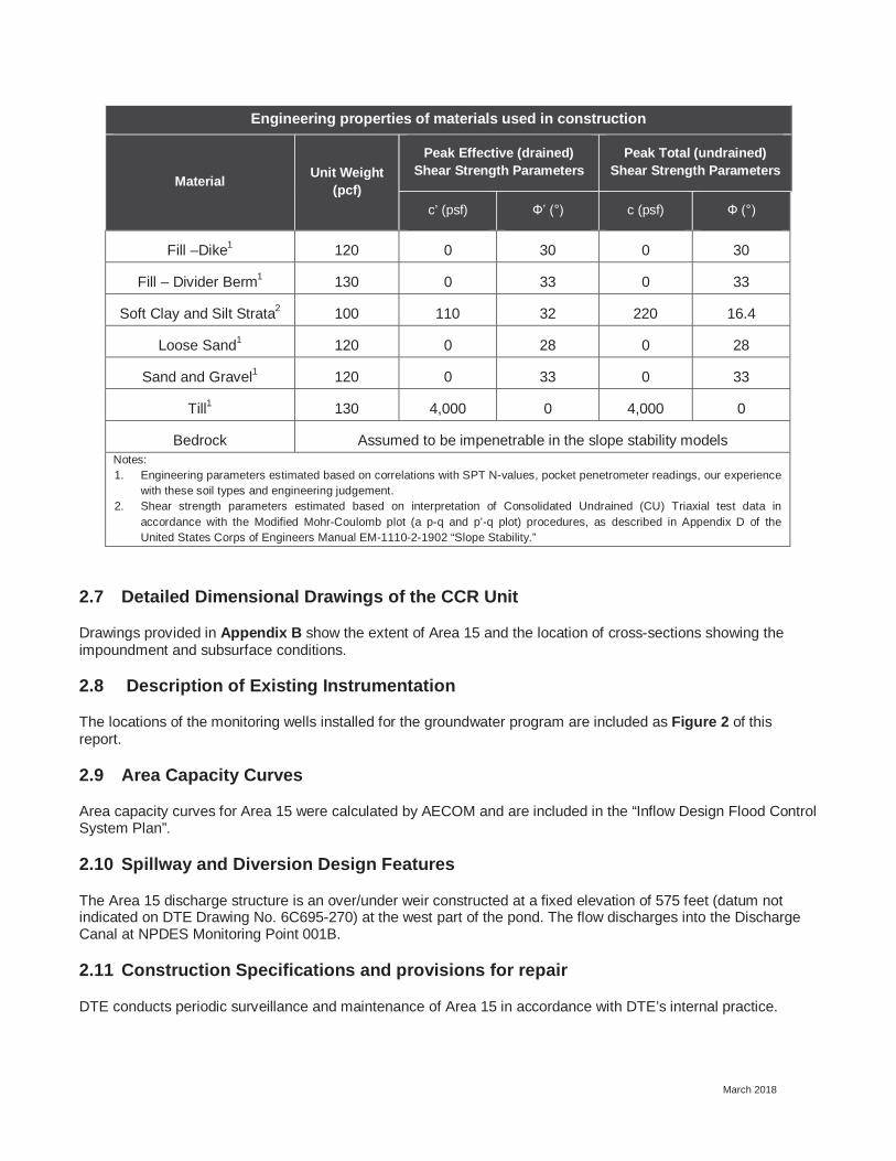
2.6 Engineering properties of materials used in construction
Records of material testing performed during construction of the basin and perimeter dikes from 1968 to 1970 are not available. Presented below are engineering properties of the differing soil materials collected during the geotechnical investigation in November of 2017.
March 2018
Engineering properties of materials used in construction
Material Unit Weight (pcf)
Peak Effective (drained) Shear Strength Parameters
Peak Total (undrained) Shear Strength Parameters
c’ (psf) c (psf)
Fill –Dike1 120 0 30 0 30
Fill – Divider Berm1 130 0 33 0 33
Soft Clay and Silt Strata2 100 110 32 220 16.4
Loose Sand1 120 0 28 0 28
Sand and Gravel1 120 0 33 0 33
Till1 130 4,000 0 4,000 0
Bedrock Assumed to be impenetrable in the slope stability modelsNotes:1. Engineering parameters estimated based on correlations with SPT N-values, pocket penetrometer readings, our experience
with these soil types and engineering judgement.2. Shear strength parameters estimated based on interpretation of Consolidated Undrained (CU) Triaxial test data in
accordance with the Modified Mohr-Coulomb plot (a p-q and p’-q plot) procedures, as described in Appendix D of the United States Corps of Engineers Manual EM-1110-2-1902 “Slope Stability.”
2.7 Detailed Dimensional Drawings of the CCR Unit
Drawings provided in Appendix B show the extent of Area 15 and the location of cross-sections showing the impoundment and subsurface conditions.
2.8 Description of Existing Instrumentation
The locations of the monitoring wells installed for the groundwater program are included as Figure 2 of this report.
2.9 Area Capacity Curves
Area capacity curves for Area 15 were calculated by AECOM and are included in the “Inflow Design Flood Control System Plan”.
2.10 Spillway and Diversion Design Features
The Area 15 discharge structure is an over/under weir constructed at a fixed elevation of 575 feet (datum not indicated on DTE Drawing No. 6C695-270) at the west part of the pond. The flow discharges into the Discharge Canal at NPDES Monitoring Point 001B.
2.11 Construction Specifications and provisions for repair
DTE conducts periodic surveillance and maintenance of Area 15 in accordance with DTE’s internal practice.

March 2018
2.12 Knowledge of Structural Instability
DTE personnel were questioned to identify historical information that could have been indicative of structural instability. DTE revealed that there are no records or knowledge of structural instability associated with Area 15.

AECOM History of Construction ReportDTE Monroe Power Plant Area 15
AECOM (2018) “Inflow Design Flood Control System”
AECOM (2018). “Safety Factor Assessment”
GZA Geoenvironmental (2011) “Final Report, Round 7 Dam Assessment, DTE Energy Monroe Power Plan, Fly Ash Basin and Bottom Ash Stormwater Pond”
U.S. Environmental Protection Agency [USEPA]. (2015). Standards for the Disposal of Coal Combustion Residuals in Landfills and Surface Impoundments. 40 CFR §257. Federal Register 80, Subpart D, April 17, 2015.
U.S. Environmental Protection Agency [USEPA]. (2018) Waters Geoviewer Mapper (2016). https://www.epa.gov/waterdata/waters-geoviewer
3 References


Figures

JOB NO. 60489524
LEGEND:Boundary of InactiveBottom Ash Basin
CREATED BY: KLP
DATE: 3/22/2018
FIGURE 1SITE LOCATION MAP
Monroe Power Plant
Doc
umen
t Pat
h: G
:\Cin
cinn
ati\D
CS
\Pro
ject
s\G
IS\D
\DTE
\Mon
roe
Plan
t\Fig
1_Si
te L
ocat
ion
Map
(3-2
2-20
18).m
xd
1 inch = 907 feetSCALE
Lake Erie
W i s c o nsin
I n d i ana O h ioI l l i nois
M i c h igan
Monroe County, Michigan
Aerial Copyright:© 2013 NationalGeographic Society, i-cubed and GoogleEarth 2016 Aerial Imagery
³0 750 1,500
Feet
Inactive Bottom Ash Basin

!A
!A
!A
!A
"/
!A!A
"/
!A
!A
!A
!A!A
!A
"/
!A
"/
"/
!A
SB-29/19/2017
SB-19/19/2017
SB-39/25/2017
MW-9S9/19/2017
MW-14S9/22/2017
MW-15S9/26/2017
MW-13S9/21/2017
MW-12S9/22/2017
MW-11S9/21/2017
MW-10S9/20/2017
SB-69/22/2016
SB-59/27/2016
MW-5S10/4/2016
MW-4S9/26/2016
MW-2S9/19/2016
MW-7S/7D9/28/2016
MW-1S/1D9/19/2016
MW-3S/3D9/20/2016
MW-8S/8D9/30/2016
JOB NO. 60489524
LEGEND:
!ANew MonitoringWell Location
!AExistingMonitoring Well
"/
Soil BoringLocation(LithologyOnly)
Unit SeparationBerm
ApproximatePlant BoundaryApproximateBoundary ofInactive BottomAsh Basin
CREATED BY: KLP
DATE: 11/30/2017
FIGURE 2CCR MONITORING WELL
NETWORK WITH INSTALLATION DATE
Monroe Power Plant
Doc
umen
t Pat
h: J
:\Pro
ject
\GIS
\D\D
TE\M
onro
e P
lant
\DTE
_Mon
roe_
MI_
Wel
l Loc
atio
n M
ap_1
1302
017.
mxd
1 inch = 700 feetSCALE
Conveyance Lines to Fly Ash Basin
Dis
char
ge C
anal
Lake Erie
W i s c o n s i n
I n d i a n a O h i oI l l i n o i s
M i c h i g a n
Monroe County, Michigan
Separation Berm
Aerial Source: Esri, DigitalGlobe, GeoEye, EarthstarGeographics, CNES/Airbus DS, USDA, USGS,AeroGRID, IGN, and the GIS User Community andGoogle Earth 2016 Aerial Imagery
³0 700 1,400
Feet

Appendix AHistorical Aerial Photography


Appendix BConstruction and Site Drawings


