history revisited - ballistics of tampella 160 … · mortar bomb designs used even today ......
TRANSCRIPT
HISTORY REVISITED - BALLISTICS OF TAMPELLA 160 AND 300 MM MORTAR BOMBS
Ari Makkonen, Jukka Tiainen, Vesa Toivonen and Eeva Makkonen
Patria Weapon Systems P.O.Box 18 FIN-38200 Vammala FINLAND
As a part of the 70th anniversary of mortar production in Finland, a review of the history of lesser known Tampella 160 mm and 300 mortars and their ammunition was carried out. As a part of this review, internal, external and terminal ballistics of some projectiles of interest was analyzed using modern projectile analysis software like FNGUN, PDS and SPLIT-X. The results of the analyses were compared to test data from the archives of Tampella and Finnish Defence Forces whenever such data was available.
HISTORY
Finnish company Tampereen Pellava-ja Rauta-Teollisuus Osake-Yhtiö (Tampere
Linen and Iron Works Ltd), better known as "Tampella" started weapons production in 1932 and had by 1939 established itself as a mortar producer both for the Finnish army and export market. Full speed production of 81 and 120 mm mortars, ammunition and weapons repair work for the Finnish army continued throughout the Winter War (1939-40) and the Continuation War (1941-44)
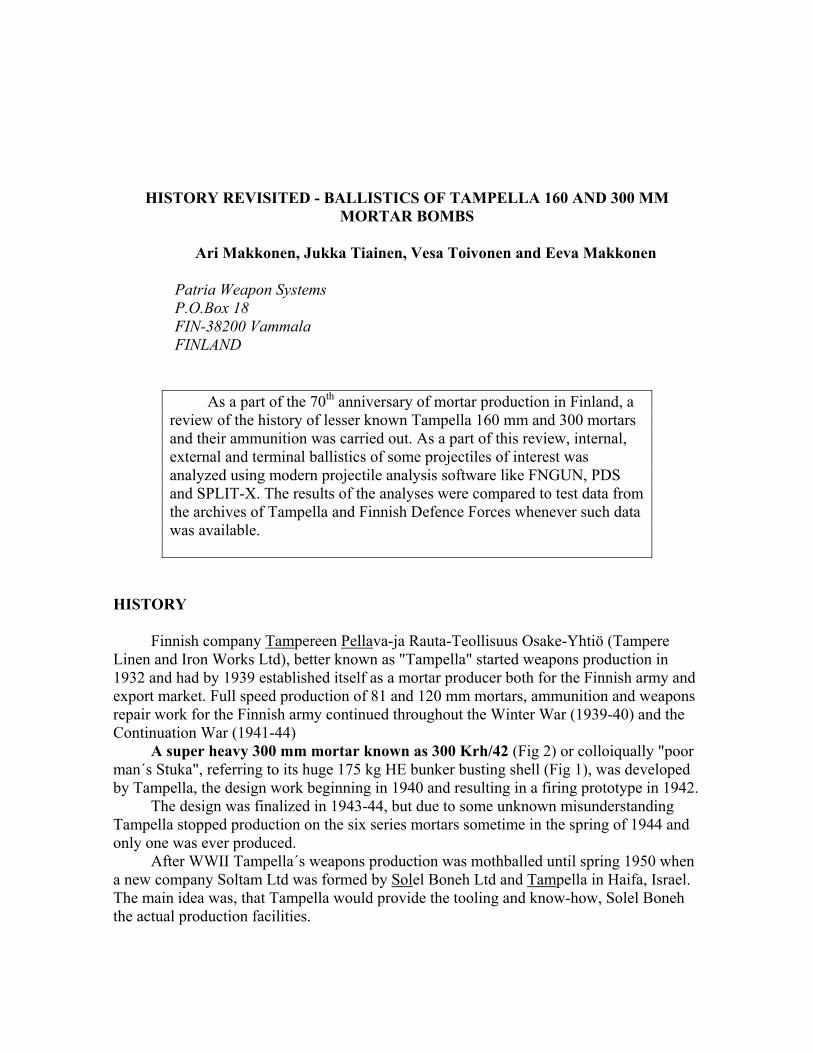
A super heavy 300 mm mortar known as 300 Krh/42 (Fig 2) or colloiqually "poor man´s Stuka", referring to its huge 175 kg HE bunker busting shell (Fig 1), was developed by Tampella, the design work beginning in 1940 and resulting in a firing prototype in 1942.
The design was finalized in 1943-44, but due to some unknown misunderstanding Tampella stopped production on the six series mortars sometime in the spring of 1944 and only one was ever produced.
After WWII Tampella´s weapons production was mothballed until spring 1950 when a new company Soltam Ltd was formed by Solel Boneh Ltd and Tampella in Haifa, Israel. The main idea was, that Tampella would provide the tooling and know-how, Solel Boneh the actual production facilities.
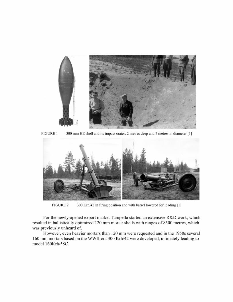
FIGURE 1 300 mm HE shell and its impact crater, 2 metres deep and 7 metres in diameter [1]
FIGURE 2 300 Krh/42 in firing position and with barrel lowered for loading [1]
For the newly opened export market Tampella started an extensive R&D work, which
resulted in ballistically optimized 120 mm mortar shells with ranges of 8500 metres, which was previously unheard of.
However, even heavier mortars than 120 mm were requested and in the 1950s several 160 mm mortars based on the WWII-era 300 Krh/42 were developed, ultimately leading to model 160Krh/58C.
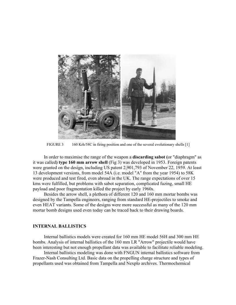
FIGURE 3 160 Krh/58C in firing position and one of the several evolutionary shells [1]
In order to maximise the range of the weapon a discarding sabot (or "diaphragm" as
it was called) type 160 mm arrow shell (Fig 3) was developed in 1953. Foreign patents were granted on the design, including US patent 2,901,793 of November 22, 1959. At least 13 development versions, from model 54A (i.e. model "A" from the year 1954) to 58K were produced and test fired, even abroad in the UK. The range expectations of over 15 kms were fulfilled, but problems with sabot separation, complicated fuzing, small HE payload and poor fragmentation killed the project by early 1960s.
Besides the arrow shell, a plethora of different 120 and 160 mm mortar bombs was designed by the Tampella engineers, ranging from standard HE-projectiles to smoke and even HEAT variants. Some of the designs were more successful as many of the 120 mm mortar bomb designs used even today can be traced back to their drawing boards. INTERNAL BALLISTICS
Internal ballistics models were created for 160 mm HE model 56H and 300 mm HE bombs. Analysis of internal ballistics of the 160 mm LR "Arrow" projectile would have been interesting but not enough propellant data was available to facilitate reliable modeling.
Internal ballistics modeling was done with FNGUN internal ballistics software from Frazer-Nash Consulting Ltd. Basic data on the propelling charge structure and types of propellants used was obtained from Tampella and Nexplo archives. Thermochemical
properties of the propellants were calculated with the method of Henderson and Hassé [2]. Dimensions and properties for the propellants are presented in Table 1.
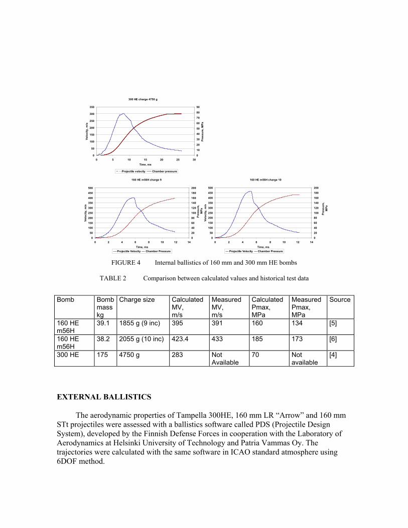
Burning rate coefficient of Vieille's law was used to achieve fit with muzzle velocity data from test firing reports. Value of Vieille's pressure exponent was chosen based on earlier modeling of Tampella 120 mm mortar propelling charges as the propellant compositions were nearly identical. The results of the modeling are illustrated in Fig 4 and comparison to test firing data is presented in Table 2.
The simulation results for the 160 mm HE-bomb agree reasonably well with experimental data. The difference between calculated and experimental chamber pressures is thought to be largely due to the crusher measurement method employed in the 1960's test firings. In a more recent Finnish study on comparability of pressure measurement methods, the difference between Handke crusher and Kistler piezoelectric measurement was found to be between 5 to 10% at the 150 to 200 MPa pressure region [3].
Piezoelectric measurement was only rarely used in test firings carried out in Finland before late 1970's, thus there are no measured pressure curves which would help improve the internal ballistic models.
TABLE 1 Projectile, Propelling charge and propellant data
Bomb Charge type Primary charge data
Primary propellant composition
Increment charge data
Increment Propellant composition
Source
160 HE m 56H, mass 39 kg
Primary 55 g 4 increments á 200 g
Flake 1.5x1.5x0.2 mm in cardboard container
Double base 55 % NC 44 % NG
Horseshoe-shaped plates in fabric socks,∅140x64, web 1.2 mm
Double base approx. 55 % NC 43 % NG
[5]
300 HE mass 175 kg
Primary 750 g 8 increments á 500 g
Flake 4.5x4.5x0.5 mm in cardboard container
Double base approx. 55 % NC 43 % NG
Flake 4.5x4.5x1.0 mm in fabric bags
Double base approx. 55 % NC 43 % NG
[4]
160 HE m56H charge 10
0
50
100
150
200
250
300
350
400
450
500
0 2 4 6 8 10 12 14
Time, ms
Velo
city
, m/s
0
20
40
60
80
100
120
140
160
180
200
Pres
sure
, M
Pa
Projectile Velocity Chamber Pressure
160 HE m56H charge 9
0
50
100
150
200
250
300
350
400
450
500
0 2 4 6 8 10 12 14
Time, ms
Velo
city
, m/s
0
20
40
60
80
100
120
140
160
180
200
Pres
sure
, M
Pa
Projectile Velocity Chamber Pressure
300 HE charge 4750 g
0
50
100
150
200
250
300
350
0 5 10 15 20 25 30
Time, ms
Ve
loci
ty, m
/s
0
10
20
30
40
50
60
70
80
90
Pres
sure
, MPa
Projectile velocity Chamber pressure
FIGURE 4 Internal ballistics of 160 mm and 300 mm HE bombs
TABLE 2 Comparison between calculated values and historical test data
Bomb Bomb
mass kg
Charge size Calculated MV, m/s
Measured MV, m/s
Calculated Pmax, MPa
Measured Pmax, MPa
Source
160 HE m56H
39.1 1855 g (9 inc) 395 391 160 134 [5]
160 HE m56H
38.2 2055 g (10 inc) 423.4 433 185 173 [6]
300 HE 175 4750 g 283 Not Available
70 Not available
[4]
EXTERNAL BALLISTICS
The aerodynamic properties of Tampella 300HE, 160 mm LR “Arrow” and 160 mm STt projectiles were assessed with a ballistics software called PDS (Projectile Design System), developed by the Finnish Defense Forces in cooperation with the Laboratory of Aerodynamics at Helsinki University of Technology and Patria Vammas Oy. The trajectories were calculated with the same software in ICAO standard atmosphere using 6DOF method.
The projectiles were first modeled with a CAD software in order to get the required input data for the ballistics software, including the center of gravity and axial and transverse inertia.
300 HE
Very little data remains from the test firings related to the 300mm mortar. However,
there is a document from demonstrational firings on July 10, 1944 [4]. Three different charges were used in the firing, but unfortunately the muzzle velocities were not documented. The velocities used in the external ballistics calculations are taken from the internal ballistics simulations.
Drag Coefficient
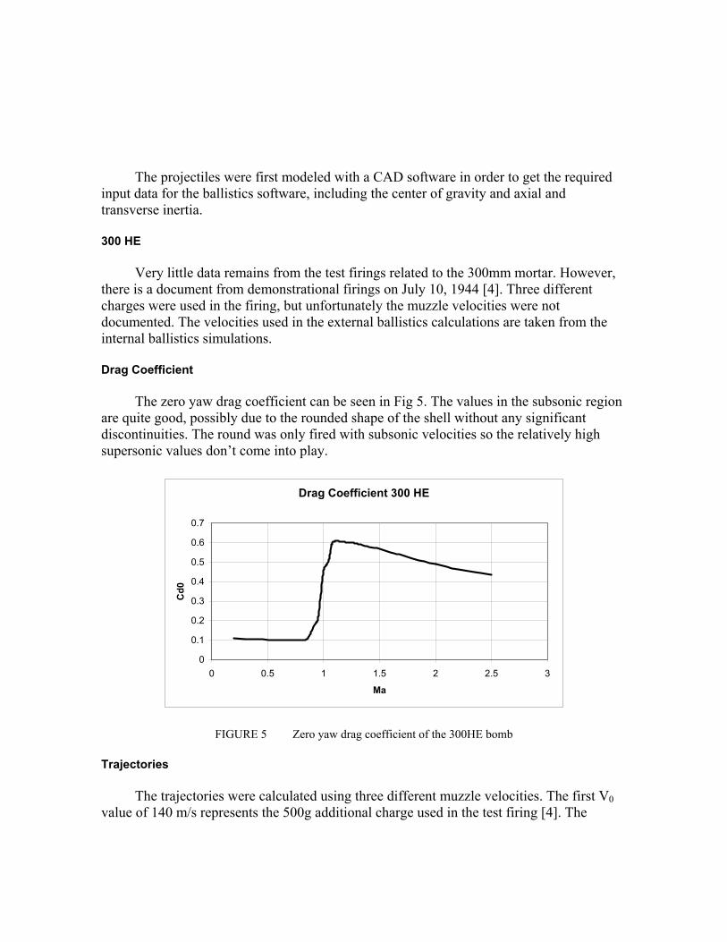
The zero yaw drag coefficient can be seen in Fig 5. The values in the subsonic region
are quite good, possibly due to the rounded shape of the shell without any significant discontinuities. The round was only fired with subsonic velocities so the relatively high supersonic values don’t come into play.
Drag Coefficient 300 HE
0
0.1
0.2
0.3
0.4
0.5
0.6
0.7
0 0.5 1 1.5 2 2.5 3
Ma
Cd0
FIGURE 5 Zero yaw drag coefficient of the 300HE bomb
Trajectories The trajectories were calculated using three different muzzle velocities. The first V0
value of 140 m/s represents the 500g additional charge used in the test firing [4]. The

second value is for a 2000g augmenting charge. The third calculation was run for the 4000g augmenting charge using V0 283 m/s (Table 2).
TABLE 3 Calculated ranges for the 300HE round in ICAO conditions
V0 (m/s) Elevation (°) Time of Flight (s) Distance (m) 140 47.5 20.8 1911 211 47.5 31.0 4163 283 47.5 41.0 7109
The calculated distances are roughly 200...400 m (9...5%) short of those shown in the
Tampella test firing document [3], the error percentage decreasing with the muzzle velocity. This can be due to several things. Firstly, there can be an error in the muzzle velocities, since the values encountered in the firing are not known. Secondly, the ballistic weather on the firing day, apart from the ambient temperature (+20°C), is not known.
Thirdly, although it has been shown in the simulations previously that the PDS ballistic software can predict the aerodynamic properties relatively well, there is always a level of uncertainty in such engineering level simulations. Dynamic Stability
The dynamic stability was assessed by 6DOF trajectory calculations. The results are
shown in Fig 6 below. The stability parameter was calculated for one trajectory, the muzzle velocity being 283 m/s and the elevation angle being 47.5°.
Stability Parameter 300HE V0 283 m/s
-0.8
-0.7
-0.6
-0.5
-0.4
-0.3
-0.2
-0.1
0
0 5 10 15 20 25 30 35 40 45
Time
Stab
.Par
am. S
low
Fre
q. (1
/s)
FIGURE 6 Dynamic stability of the 300HE round, muzzle velocity 283 m/s
The stability parameter here is the inverse of the time-to-half/double-amplitude of the precession i.e. the slow frequency disturbance. This indicates how many times a disturbance will be halved/doubled in a unit time, a negative value meaning stable behaviour. From the plot it can be seen that the projectile is dynamically stable throughout the trajectory.
160 mm LR „Arrow“ and 160STt „Super Tampella“
The lack of technical information related to the 160 LR “arrow” round also affected
the external ballistics simulations. The information that can be found from Tampella archives is somewhat confusing or controversial and definitely imperfect. During the development the weight of the projectile and the geometry has changed quite significantly. The geometry which was used in the simulations is “58K”, i.e. the 12th version from the year 1958.
The weight of the projectile was measured from an existing empty shell. From a technical drawing – the only one remaining and apparently the same version as the existing shell – a CAD model was generated which helped to determine the weight of the filled projectile. 26.4 kg was used in the simulations, the weight of TNT filling being 1.7 kg.
In the late 1960’s Tampella developed a range of very streamlined projectiles for 60 mm, 81 mm, 120 mm and 160 mm mortars. The properties of the 160 STt round, nicknamed Sonny W, or “Super Tampella” are assessed here. That name is not too extravagant when the aerodynamic properties are examined.
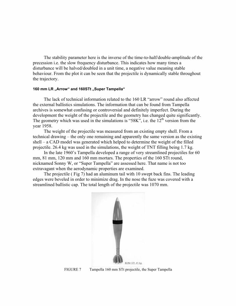
The projectile ( Fig 7) had an aluminum tail with 10 swept back fins. The leading edges were beveled in order to minimize drag. In the nose the fuze was covered with a streamlined ballistic cap. The total length of the projectile was 1070 mm.
FIGURE 7 Tampella 160 mm STt projectile, the Super Tampella

Drag Coefficient
The zero yaw drag coefficients for 160 arrow and 160 Super Tampella can be seen in
Fig 8 below. The interesting feature are the “poor” values of the "arrow" projectile compared to the Super Tampella. The exposed blunt fins of the arrow projectile increase its drag significantly. On the other hand the small frontal area due to the “subcaliber” nature of the round decreases the actual drag force, enabling reasonably long firing distances.
Drag Coefficient 160 LR "Arrow" and 160 STt
0
0.1
0.2
0.3
0.4
0.5
0.6
0.7
0 0.5 1 1.5 2 2.5
Ma
CD
0 160 LR160STt
FIGURE 8 Zero yaw drag coefficients of 160 mm LR arrow and 160 STt projectiles
Trajectories Due to the fact that inadequate data remains from the charge system of the 160 mm
LR “Arrow” round, the trajectories for that round were calculated for one illustrative muzzle velocity of 530 m/s and elevation of 45 degrees.
The properties of 160 STt are better documented and even test firing results can be found. An original Muzzle velocity – Pressure/ Range plot can be found as well, which is shown in Fig 9. This table is calculated for “standard Finnish weather”, the temperature being +0°C and the air pressure 1000 mbar. 6DOF calculations were carried out in order to repeat the results. With muzzle velocity of 400 m/s and elevation angle of 50°, the calculated range is 9725 m, which is very close to the value in the original table, thus validating the further calculations.
Muzzle velocities of over 420 m/s were achieved in the test firings when firing 160 Super Tampella [7]. With velocity of 414 m/s the projectile would have a range of nearly 10.5 km in ICAO conditions, as can be seen from Table 4.

Table 4 also shows the calculated range for the 160 arrow projectile. A maximum range of 15 km can be achieved with V0 of 530 m/s. The projectile was presented in the 1994 Jane’s Ammunition Handbook along with a range claim of 15 km. However, its weight was stated to be 30.42 kg, which continues the trend of confusing information related to this projectile.
FIGURE 9 A range vs. muzzle velocities graph for 160STt in 0°C ambient temperature.
TABLE 4 Calculated trajectories for 160 STt and 160 LR arrow projectiles
Projectile V0 (m/s) Elevation (°) Time of Flight (s) Range (m) 160 Super Tampella 414 45 49.2 10422 160 LR Arrow 530 45 60.3 14996
Dynamic Stability
The dynamic stability was assessed in the similar manner as in the 300 mm HE case.
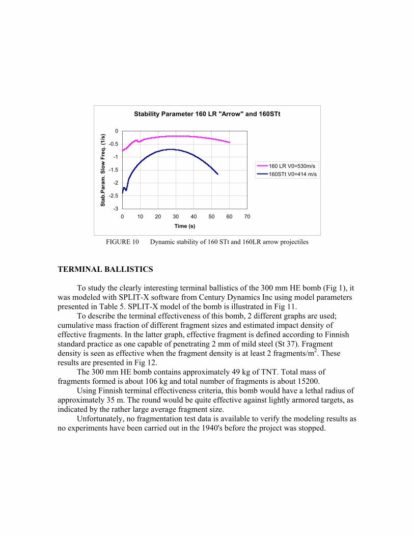
The result is shown in Fig 10 for the 160 Arrow and 160 Super Tampella. 160 Super Tampella is dynamically more stable than the arrow projectile, but both projectiles remain stable throughout the flight.
Stability Parameter 160 LR "Arrow" and 160STt
-3
-2.5
-2
-1.5
-1
-0.5
0
0 10 20 30 40 50 60 70
Time (s)
Stab
.Par
am. S
low
Fre
q. (1
/s)
160 LR V0=530m/s160STt V0=414 m/s
FIGURE 10 Dynamic stability of 160 STt and 160LR arrow projectiles
TERMINAL BALLISTICS
To study the clearly interesting terminal ballistics of the 300 mm HE bomb (Fig 1), it was modeled with SPLIT-X software from Century Dynamics Inc using model parameters presented in Table 5. SPLIT-X model of the bomb is illustrated in Fig 11.
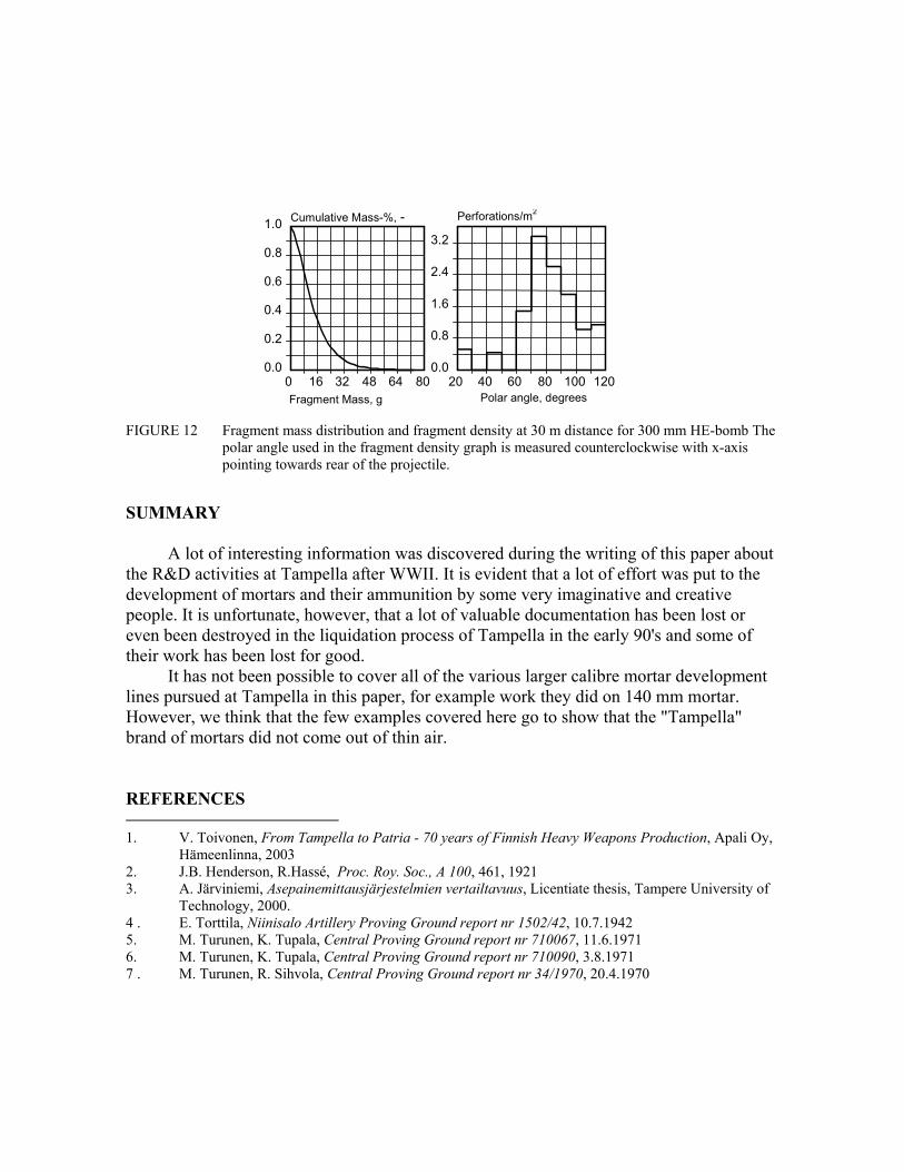
To describe the terminal effectiveness of this bomb, 2 different graphs are used; cumulative mass fraction of different fragment sizes and estimated impact density of effective fragments. In the latter graph, effective fragment is defined according to Finnish standard practice as one capable of penetrating 2 mm of mild steel (St 37). Fragment density is seen as effective when the fragment density is at least 2 fragments/m2. These results are presented in Fig 12.
The 300 mm HE bomb contains approximately 49 kg of TNT. Total mass of fragments formed is about 106 kg and total number of fragments is about 15200.
Using Finnish terminal effectiveness criteria, this bomb would have a lethal radius of approximately 35 m. The round would be quite effective against lightly armored targets, as indicated by the rather large average fragment size.
Unfortunately, no fragmentation test data is available to verify the modeling results as no experiments have been carried out in the 1940's before the project was stopped.

1
919 mm
299.5 mm
FIGURE 11 SPLIT-X model of Tampella 300 mm HE-bomb
TABLE 5. Parameters used in modeling terminal ballistics of the Tampella 300 mm HE bomb
BOMB 300 HE EXPLOSIVE Material Name: TNT Density: 6900 m/s Gurney Velocity: 2400 m/s CASING Material Type: Natural Material Name: Cast Steel Density: 7850 kg/m³ Gas Leakage Factor: 1 - Ultimate Strength: 750 MPa Elastic Modulus: 206GPa Fracture Toughness: 35 MPam1/2 Specific Heat: 450 J/kg/K Th. Conductivity: 72 W/m/K Th. Softening: 0.00067 1/K Mass Distribution: Mott (generalized) Distr. Parameter: 1 Shear Energy Scale: 1 Tensile Energy Scale: 1 Aspect Ratio: Calculated
0 16 32 48 64 80Fragment Mass, g
0.0
0.2
0.4
0.6
0.8
1.0 Cumulative Mass-%, -
20 40 60 80 100 120Polar angle, degrees
0.0
0.8
1.6
2.4
3.2
Perforations/m2
FIGURE 12 Fragment mass distribution and fragment density at 30 m distance for 300 mm HE-bomb The
polar angle used in the fragment density graph is measured counterclockwise with x-axis pointing towards rear of the projectile.
SUMMARY
A lot of interesting information was discovered during the writing of this paper about the R&D activities at Tampella after WWII. It is evident that a lot of effort was put to the development of mortars and their ammunition by some very imaginative and creative people. It is unfortunate, however, that a lot of valuable documentation has been lost or even been destroyed in the liquidation process of Tampella in the early 90's and some of their work has been lost for good.
It has not been possible to cover all of the various larger calibre mortar development lines pursued at Tampella in this paper, for example work they did on 140 mm mortar. However, we think that the few examples covered here go to show that the "Tampella" brand of mortars did not come out of thin air. REFERENCES 1. V. Toivonen, From Tampella to Patria - 70 years of Finnish Heavy Weapons Production, Apali Oy,
Hämeenlinna, 2003 2. J.B. Henderson, R.Hassé, Proc. Roy. Soc., A 100, 461, 1921 3. A. Järviniemi, Asepainemittausjärjestelmien vertailtavuus, Licentiate thesis, Tampere University of
Technology, 2000. 4 . E. Torttila, Niinisalo Artillery Proving Ground report nr 1502/42, 10.7.1942 5. M. Turunen, K. Tupala, Central Proving Ground report nr 710067, 11.6.1971 6. M. Turunen, K. Tupala, Central Proving Ground report nr 710090, 3.8.1971 7 . M. Turunen, R. Sihvola, Central Proving Ground report nr 34/1970, 20.4.1970