hitachi chemical
TRANSCRIPT


�
No.54/March 2012
● Hitachi Chemical’s R&D Strategy–Contributing to Society by Developing Superior Technologies and Products to Pioneer a New Era– 3
Itsuo Watanabe [Executive Officer]
● Thermal Management Materials 5
Teiichi Inada [Tsukuba Research Laboratory]
● Recent Technology of Powder Metallurgy and Applications 12
Tadayuki Tsutsui [Hitachi Powdered Metals Co., Ltd.]
● Thermally Conductive Metal Substrate 21
Kazumasa Fukuda [Tsukuba Research Laboratory]
● Thermally Conductive Flexible Substrate with Heat-resistant Adhesive Layer 23
Masato Nishimura [Tsukuba Research Laboratory]
● Helical-groove Bearing with Long Life for Fan Motors 25
Hidekazu Tokushima [Hitachi Powdered Metals Co., Ltd.]
● Sintered Heat Resistant Material for Turbochargers 27
Hideaki Kawata [Hitachi Powdered Metals Co., Ltd.]
● Photosensitive Solder Resist Film for Semiconductor Package “FZ Series” 29
Toshimasa Nagoshi . Shigeo Tanaka . Kimihiro Yoshizako [Printed Wiring Board Materials Business Sector]
Shizu Fukuzumi . Kazuhiko Kurafuchi [Tsukuba Research Laboratory]
● Reliability of Cu Wire Packages and Molding Compounds 31
Hidenori Abe [Electronic Materials Business Sector]
● Techniques for Analyzing Underfill Materials for Semiconductor Packages 33
Naoya Suzuki [Tsukuba Research Laboratory]
● Halogen Free, High Elasticity and Low CTE Multilayer Material「MCL-E-700G(R)」 35
Shinji Tsuchikawa [Tsukuba Research Laboratory]
● Anti-Fingerprint UV Curable Hard Coatings 37
Takeshi Nakamura [Material Polymer Science Sector]
● Application of Layer-by-layer Assembled Nanoparticles to Anti-reflection Film 39
Nobuaki Takane [Tsukuba Research Laboratory]
Hitachi ChemicalTechnical Report
■Anti-Reflection Film Produced Using Layer-by-layer AssemblyReport: Application of Layer-by-layer Assembled Nanoparticles
to Anti-reflection Film (p.39)
Preface
CONTENTS
Review
Report

� Hitachi Chemical Technical Report No.54
Hitachi Chemical has its origin in 1912 (Meiji 45), when Hitachi Ltd. began research on oil-
based varnish. In 1962, Hitachi Chemical was established with the independence of Hitachi Ltd.’s
chemical department from the company. Since its founding, Hitachi Chemical has continued
to research and develop new businesses and products based on its fundamental technologies,
including material technologies, process technologies, and evaluation technologies. These
technologies have been fostered by the development of the company’s fountainhead products,
including insulating varnish, laminated plates, insulators, and carbon brushes. Along with
integrating these fundamental technologies, Hitachi Chemical is expanding business by focusing
on four key business domains: “Information Communication and Displays,” “Automobiles,”
“Environment and Energy,” and “Life Sciences.”
In area of communication with customers, Hitachi Chemical is advancing R&D under the
business model of “Material System Solution” (MSS). This model seeks to provide our customers
with their desired optimum materials, services, and solutions as a suite of systems. We are
carrying out this model by combining and adapting our wide-ranging fundamental technologies
and extensive business domains, as mentioned above, under the corporate vision of “Contributing
to society by developing superior technologies and products to pioneer a new era.”
【Creating New Products by Integrating and Cultivating Fundamental Technologies】
Since the founding of Hitachi Chemical, we have been strengthening our materials
technologies, including technologies for adhesion, insulation, conduction, heat conduction,
transparency, heat resistance, photosensitivity, and fine par ticles, and our process and
evaluation technologies, including technologies for combinations, coatings, moldings, and
surface treatments, by integrating and cultivating our diverse technologies. Hitachi Chemical
is maintaining superiority in polymer technologies, the fountainhead of our technologies. We
are developing new products that differentiate us from our competitors, steadfastly devoting
ourselves to our “MSS” business model, which contributes to our customers’ value creation,
and advancing the development of new products that provide solutions to our customers. An
example of product development integrating the fundamental technologies of Hitachi Chemical
is our circuit connection (anisotropically conductive) film for liquid crystal display. This film
integrates the functions of adhesion and insulation with the functions of conduction. This product
was discovered during a process to extend adhesive film technology to semiconductors. Initially,
we had sought to create an isotropic film. However, there is a tradeoff relationship between
adhesiveness and conductivity, and we discovered a new property in which conductivity differs
between the inner film surface and the direction of film thickness. As a result, we created
a material that achieves fine adhesion in the micron order, which is dif ficult to accomplish
with conventional solder technology. Hitachi Chemical’s transparent interlayer filling film,
commercialized in 2010 and superior for mitigating shocks to touch panel screens, is another
integrative product combining the technologies for adhesion and transparency which we have
Hitachi Chemical’s R&D Strategy− Contributing to Society by Developing Superior
Technologies and Products to Pioneer a New Era −
PREFACE
Executive Officer
Deputy General Manager
New Business Development Headquarters
General Manager
Tsukuba Research Laboratory
Itsuo Watanabe

�Hitachi Chemical Technical Report No.54
cultivated to this day. We are moving forward with developing this product for application to touch
panels, whose market is expected to explode in the future.
【Strengthening R&D in Environment and Energy】
Because the markets for “Information Communication/Displays” and “Automobiles,”
which are drivers of sales and profit for Hitachi Chemical, are expected to grow in the future,
we will continue to advance the development of new products by integrating and cultivating
our fundamental technologies as the mainstay of our business. In addition, we are devoting
ourselves more than ever to the area of “Environment and Energy,” where significant growth is
anticipated. We are accelerating the creation of new products in this area. For example, in the
area of solar cells, which are expected to grow in demand as a source of renewable energy, we
recently productized a conductive film as a substitute for solder. Utilizing the anisotropically
conductive film technology as described above, this film can be in direct contact with tab lines
and the electrodes of solar cells. Among other products, we have also productized a heat-resistant
insulating resin paste that integrates the functions of heat-resistance and insulation. We will
continue to advance the development of new products that contribute to improving the conversion
efficiency of solar cells. We are also creating new products in the area of “Environment and Life
Sciences” by expanding new core technologies through the development of naturally-derived
materials, utilizing Hitachi Chemical’s material technologies and analytic/precision technologies,
and through joint development with external research institutions.
【Prompt Commercialization of R&D Themes】
In October of 2010, we considered the market trends of the four major business areas
targeted by Hitachi Chemical as described above and the company’s technological potential. This
examination resulted in seven new trans-company business creation projects under the theme
of “growth domains.” Also, a president-sponsored committee studied and classified marketing
issues and inter-departmental issues. The results of this review have led to the strengthening of
collaborations between the sales and production departments, for example, to achieve early-stage
commercialization of new products.
【Intellectual Property Strategy to Strengthen Competitiveness】
In addition to the R&D strategies described above, Hitachi Chemical views intellectual
property as a resource critical to our business strategies. Based on the philosophy of “actively
obtaining and utilizing effective patents to support business strategies,” we are working diligently
to build a strong patents portfolio. Specifically, in the process of developing Hitachi Chemical’s
“MSS” business model, we are striving to obtain patents not only in the areas of components
and materials, but also in the area of processes that utilize these assets. We are devoting energy
to establishing rights in these areas. We are actively utilizing this obtained patents portfolio by
connecting it to Hitachi Chemical’s business strategies. As a result of inventions and discoveries
related to our R&D achievements and prompt filings and activities to establish rights, Hitachi
Chemical has risen in rank against our competitors in Patent Result Co. Ltd.’s “Ranking of
Capability to Contain Other Companies with Patents.”
【Conclusion】
By advancing our R&D activities as described above, we at Hitachi Chemical seek to
continue to focus on realizing our corporate vision, “Contributing to society by developing
superior technologies and products to pioneer a new era.”

� Hitachi Chemical Technical Report No.54
There are a lot of difficult problems related to thermal energy when trying to solve global warming, heat dissipation from electronic devices, and the shortage of electricity during summer 2011. The integrated thermal management materials of Hitachi Chemical are applicable to solving these problems. In this paper, the features and applications of thermal management materials, such as those used in thermally conductive materials, thermally insulating materials, and thermoelectric modules and devices, are explained. Finally, our approach to the environmental thermal problem is discussed.
Heat, similar to potential energy and electrical energy, is a form of energy. The theromodynamics - academic inquiry into heat - began at the time of Watt’s invention of the steam engine and was established in the early 20th century by questioning “What is thermal energy?” and “How can thermal energy be maximally utilized?”1,2) The laws of thermodynamics state that the total sum of energy in an isolated system is constant, and when processes are irreversible, entropy must increase. However, the speed of heat flow and the rate of entropy increase in a system are not determined. We can easily control the speed of heat flow and the rate of entropy increase to a certain extent by changing the system’s size, structure, and materials. Thermal management materials, the topic of this paper, are materials that bring about various effects by using this controllability appropriately. The targets of this research are primarily to solve thermal problems and to develop materials related to electrical equipment, automobiles, and housing. Because their heat generation density is relatively low, it is easy to control the speed of heat flow of these products with thermal management materials. In this paper, the functions and features of these materials created by Hitachi Chemical, which are useful in controlling heat flow, are described.
Now, when faced with today’s problems, such as urban heat islands, global warming, and the Fukushima nuclear power plant accidents as a result of the Great East Japan Earthquake and the ensuing lack of electricity, one cannot help but feel the difficulty in controlling heat. However, we must not stand paralyzed in the face of these problems. We still hope that we can contribute something. Our efforts to address these problems are discussed below.
First of all, heat dissipation materials to control heat flow are discussed. Heat dissipation materials are critical for recent compact electrical devices and hybrid cars. Because the temperature of these products must be kept below certain levels, thermal management materials are used to dissipate the heat produced by CPUs or power semiconductor devices. As shown in Figure 1, our heat dissipation technologies consist of 1) nano-structure control (molecular design of epoxy resin with a mesogen structure) and 2) orientation control.
In collaboration with Hitachi, Ltd., we have developed highly thermally conductive epoxy resin with a mesogen structure3,4). By combining this resin with our hardening agent technology and technology for high loading of ceramic fillers, we have developed an adhesive insulating sheet that can achieve thermal conductivity of 5–10 w/mK5-7). The typical properties of this sheet are shown in Table 1. The sheet not only has outstanding thermal conductivity, it also has high heat resistance and strong adhesion. These technologies were described in detail in the last issue6). We have begun to mass produce the sheet and it has been applied to power modules and LEDs.
The orientation control technologies that control the orientation of graphite particles arranged vertically in a sheet of 150-500 µm thickness, as shown in Figure 1b, are our proprietary. Using our original graphite particles with high thermal conductivity in flake form and elastic resin, we developed a new process that orients the graphite vertically in the sheet. As a result, the sheet exhibits thermal conductivity more than several ten times than that of sheets using spherical graphite particles or sheets using horizontally oriented graphite particles in scale form8-9). Besides being used to dissipate the heat from the CPUs in high-end servers, the sheet is also being used to reduce the thermal resistance of thermoelectric converter modules, as described below.
By combining our original materials and technologies, we have also brought various thermally conductive materials into the market. Besides of heat dissipation, distinguished feature that these technologies have in common is additional functions. These materials are briefly described below.
The change from incandescent and fluorescent lamps to LEDs is accelerating due to the recent demand for saving energy.
Review Paper ①
1 Introduction
2 Heat Dissipation Materials
Thermal Management MaterialsTeiichi Inada
New Business Development HeadquartersTsukuba Research Laboratory

�Hitachi Chemical Technical Report No.54
HT-5100M, a metal based substrate using the high thermal conducting epoxy resin, and MCF-5000I, a thin and flexible substrate with high heat dissipation ability and good workability, are applicable to LED lighting. Both of them are introduced in the “Report” section of this issue. Their additional function gives numerous features, such as enabling products to be made thin and light. Also, HT-9000ITM, a flexible heat-dissipating substrate composed of a heat-resistant adhesive layer laminated beforehand to MCF-5000I, can simplify the substrate production process by omitting the conventional process of attaching adhesive to separated substrates. These products can be applied not only to LED lighting, but also to compact batteries, automobiles, and clothing that take advantage of curved surfaces.
We have also developed a flexible and transparent heat-conducting sheet. The sheet is produced using our pattern plating transfer method10). It has a high degree of transparency with a transmittance of 90% of visible light. Also, because the sheet has
Figure 1 Hitachi Chemical’s technologies for high thermal conductivity Nanostructure controlled materials and particle orientation are our company’s base technologies.
Figure 2 Graphite particles, the thermal conductivity of a sheet, and an example of application The thermal conductivity of a sheet strongly depends on graphite particle shape and orientation.
Property Unit 5 W grade 10 W grade15 W grade
(Developed)Thermal conductivity
Xe flash methodW/m K 5.0 8〜10 12〜15
Glass transition temperatureDMA method
℃ 170〜180 165〜175 175〜200
Coefficient of thermal expansion α1 ppm/℃ 20〜22 16〜17 16〜17
Heatresistance at soldering ー >280 ℃5min >280 ℃5min >280 ℃5min
Breakdown voltage kV/200 µm >7 >7 >7
Elastic modules GPa 9〜10 10〜12 9〜10
Peel strength kN/m1.2
(Cu35 µm)1.2
(Cu35 µm)0.5 〜0.9
(Cu35 µm)
Flexibility mm Φ50-OK Φ50-OK Φ50-OK
100 µm10nm
High thermal conductivity×5
High thermal conductivity×100
b)Orientation control technologya)Nanostructure controlled materials
100μm
60
0(W
/m
K)
80
40
20
a)Shape of graphite particles
The
rmal
con
duct
ivity
Graphite-oriented
CPU
Heat spreader
b)Shape of graphite particles, orientation and thermal conductivity, and location of sheet application
Table 1 General properties of thermally conductive sheet Thermally conductive sheet shows high thermal conductivity and excellent thermal stability and adhesion strength.

� Hitachi Chemical Technical Report No.54
fine copper mesh wiring on surface of flexible polymer film, as shown in Figure 3, its thermal conductivity in the horizontal direction is 6 W/mK, 30 times that of conventional resin sheets, while it exhibits the same flexibility as conventional polymer films. This additional functions of this product are transparency which can be applied to lighting surface of LEDs and shielding ability of electromagnetic wave. Currently, we are investigating the application of this product to areas in which both a high transparency and high thermal conductivity are demanded.
We have also developed a metal based substrate that features flexibility in addition to thermal conductivity11). Because it can reduce the stress on the solder balls of the mounted devices, it has been used more than 10 years as an in-vehicle substrate. This technology is widely applied to the process of attaching materials with different coefficients of thermal expansion. Its application is being widely extended to die bonding films12) and encapsulant films13).
We propose a variety of heat dissipation materials suitable for each application. However, because of the difficulty in heat dissipation to outside in recent small electronic devices and LED lighting devices, the problems of overheating of the entire device have risen.
For such cases, it is necessary for heat to be dissipated from the chassis by radiation. Because thermal radiation follows the Stefan–Boltzmann law, it is desired to coat the surface of a high-temperature body by a high emissivity material (thermal radiation paint). Hitachi Chemical and Hitachi Chemical Industrial Materials Co., Ltd. have developed HC-001, an environmentally friendly water-based coating with superior emissivity and heat resistance. This material can be coated on uneven surfaces by spraying
Figure 4 Effect of temperature decrease by HC-001 coating on an LED light bulb Temperature decreasing effects of about 10 ℃ at the heat sink and about 7 ℃ at the substrate were achieved.
45
50
55
60
65
Without coating With coating
Sur
face
tem
p.(
℃)
Measured point
b)Temperature of LED substrate portion
63.6 ℃ 56.4 ℃
Measured point
a)Surface temperature of heat sink portion
Figure 3 Picture and pattern of transparent thermally conductive film Because of the fine Cu pattern, the film is transparent and thermally conductive.
15 um
X200
メッシュ電極
300 µm
�Hitachi Chemical Technical Report No.54
and forms a hard film after drying. Figure 4 shows an example of the heat sink of an LED light bulb painted with HC-001.The temperature at the heat sink dropped by 10 °C. The temperature at the substrate mounted on the LED dropped by 7 °C. This reduction is expected to greatly extend the life of products.
In the future, it is expected that there will be the need to secure heat dissipation paths not only by using high thermal conducting materials but also by combining various materials. Therefore, not only materials but also technologies for measuring basic physical properties related to heat, simulation technologies based on these measurement technologies, and technologies to combine materials are essential. We have begun to extend MSS (Material System Solution), the technology we have been applying to the electronic packaging materials for a long time, to the thermal management materials and have started the proposal of the optimum combination of materials. By making such proposals for a variety of electronic devices, we can shorten the time of selecting appropriate materials.
In this chapter, heat insulation, the complete opposite of heat dissipation discussed above, is discussed. The most important issue is to lower the electrical energy consumed by air-conditioning and heating. The term “saving energy” is frequently used today. However, because the first law of thermodynamics states that the total energy of an isolated system is always constant, the energy cannot be saved completely. The essence of “saving energy” is to thermodynamically control the inflow and outflow of heat between different systems and to inhibit the increase of entropy. We have a group of materials which are effective to suppress the entropy, based on our resin processing technology. Some of these materials are introduced below.
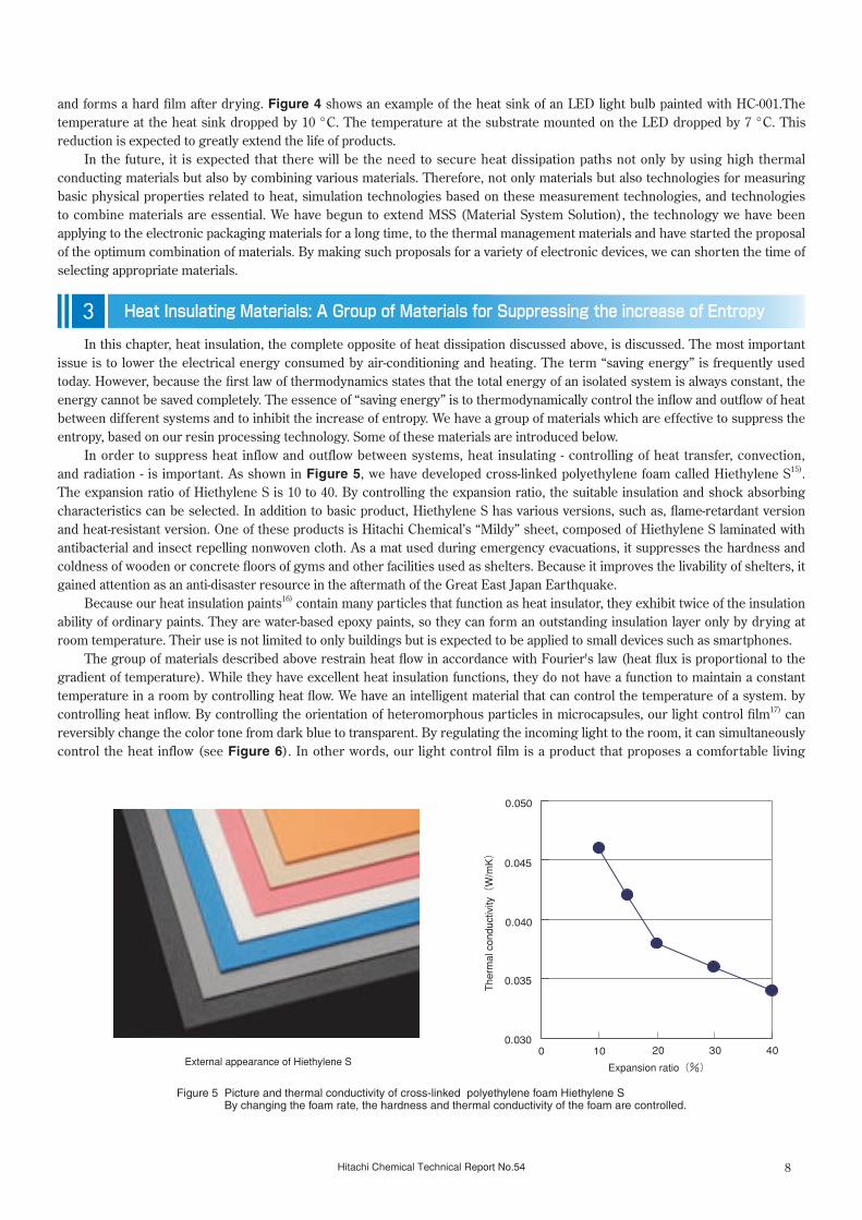
In order to suppress heat inflow and outflow between systems, heat insulating - controlling of heat transfer, convection, and radiation - is important. As shown in Figure 5, we have developed cross-linked polyethylene foam called Hiethylene S15). The expansion ratio of Hiethylene S is 10 to 40. By controlling the expansion ratio, the suitable insulation and shock absorbing characteristics can be selected. In addition to basic product, Hiethylene S has various versions, such as, flame-retardant version and heat-resistant version. One of these products is Hitachi Chemical’s “Mildy” sheet, composed of Hiethylene S laminated with antibacterial and insect repelling nonwoven cloth. As a mat used during emergency evacuations, it suppresses the hardness and coldness of wooden or concrete floors of gyms and other facilities used as shelters. Because it improves the livability of shelters, it gained attention as an anti-disaster resource in the aftermath of the Great East Japan Earthquake.
Because our heat insulation paints16) contain many particles that function as heat insulator, they exhibit twice of the insulation ability of ordinary paints. They are water-based epoxy paints, so they can form an outstanding insulation layer only by drying at room temperature. Their use is not limited to only buildings but is expected to be applied to small devices such as smartphones.
The group of materials described above restrain heat flow in accordance with Fourier's law (heat flux is proportional to the gradient of temperature). While they have excellent heat insulation functions, they do not have a function to maintain a constant temperature in a room by controlling heat flow. We have an intelligent material that can control the temperature of a system. by controlling heat inflow. By controlling the orientation of heteromorphous particles in microcapsules, our light control film17) can reversibly change the color tone from dark blue to transparent. By regulating the incoming light to the room, it can simultaneously control the heat inflow (see Figure 6). In other words, our light control film is a product that proposes a comfortable living
3 Heat Insulating Materials: A Group of Materials for Suppressing the increase of Entropy
Figure 5 Picture and thermal conductivity of cross-linked polyethylene foam Hiethylene S By changing the foam rate, the hardness and thermal conductivity of the foam are controlled.
0.030
0.035
0.040
0.045
0.050
0 10 20 30 40
Expansion ratio(%)
The
rmal
con
duct
ivity
(W
/mK
)
External appearance of Hiethylene S

� Hitachi Chemical Technical Report No.54
space. Light control glass, which has the light control film laminated to glass or polycarbonate board, is already being used as window glass in buildings and airplanes. Because the film confers a high sense of design and also effectively controls temperature, it is expected to be used in a variety of applications, such as automobiles, ships, and trains18).
The group of materials stated above can control the amount of heat flow in a wide variety of ways. However, in the end, thermal energy is not reused and migrates to a different low-temperature system. In other words, any usable energy is not obtained and the entropy increases in vain. Thus, it is necessary to convert thermal energy into electrical energy and reuse it by exploiting the temperature difference created when the thermal energy moves to a low-temperature region.
Together with Hitachi Powdered Metals Co., Ltd., and the Central Research Institute of Electric Power Industry, Hitachi Chemical has developed a thermoelectric conversion module enclosed in an airtight case by applying powder metallurgy technology19,20). An example of the product is shown in Figure 7. Besides an SiGe module that exhibits superior power generation efficiency at a heat source temperature of 600–1,000 °C (8.4 W@⊿T=630 °C), we are also developing modules, using Mg2Si, that use common elements and show better performance than SiGe at 300–600 °C. Because of the outstanding reliability of thermoelectric converter modules, they have been used as the power source of deep space probes. However, in order to use them for automobiles or homes in the future, further improvement in performance and invention to simplify installation and to lower the cost are required. Since the electricity produced by the thermoelectric converter is determined by the temperature difference, it is essential to minimize the thermal resistance between the heat souce and the module and maximize the thermal resistance inside the module. For the module to be in direct contact with the heat source, a method to lower the thermal resistance by inserting the flexible graphite-oriented sheet described above between the heat source and the module is in practical use. We plan to further increase the thermal resistance inside the module by lowering the thermal conductivity of the materials used in the module.
Figure 6 Temperature controllability of active light control film The active light control film can control room temperature and keep the room comfortable by having the color of its film changed from blue to clear.
4 A Group of Materials Related to Conversion of Thermal Energy
Vacuum metal case
55 mm
Thermoelectric converter module(SiGe)
Electric contact
Figure 7 Encapsulated thermoelectric module and device A thermoelectric module in a vacuum metal case has excellent reliability.
●Figure Surface Temperature of Color Paper
Tem
pera
ture(
℃)
60
50
40
30
20 0 2010 30 40 50 60 70
General glass
10 ℃ lower
Light control glass
Power ON
Power OFF
Light
Dark
Time(min)
●Experimental setup of quasi-sunlight exposure
General glass
Light source(1000 W/m2)
Light control glass
Color paper(black) (Exposed surface)

10Hitachi Chemical Technical Report No.54
An overview of Hitachi Chemical’s thermal management materials, mainly applied to electronic devices, is described above. Finally, We would like to discuss how Hitachi Chemical’s materials contribute, albeit humbly, to reducing CO2 gas and addressing the problem of global warming.
Solar heat reflection paint used on rooftops is an example of a thermal management material that supports the environment. It is well-known that half of the energy emitted by the sun is light in the infrared region. Thus, the temperature increase in a room can be held down by reflecting the sun’s infrared rays. Hitachi Chemical Industrial Materials Co., Ltd.’s solar heat reflection paint Hi-star Shataro21) including special pigments that block infrared rays shows an infrared reflectivity of greater than 90%. Because this paint is water-based, it is gentle to the environment. Its workability is also good because it requires a short drying time of about 30 minutes. The effects of this solar heat reflection paint are shown in Figure 8. Compared to general paints, the reflectivity of the infrared region is three times higher. This paint can thus reduce the temperature of the painted surface. In experiments simulating exposure to sunlight during the summer period, Hi-star Shataro lowered the temperature of the surface by 25 °C compared to an unpainted surface and lowered the temperature by 20 °C compared to a surface painted with conventional paint. The combination of this paint with the heat insulating paint and polyethylene foam described above would further prevent the inflow of heat from the roof.
Furthermore, in addition to heat dissipation materials, Hitachi Chemical is providing numerous materials for electronic devices, including substrate materials, and die bonding films22). The evolution in electronic devices and information technologies is expected to reduce CO2 emissions by 5% in 2020 (compared to 2000, reduction of 8.6 million tons) by:
1) reducing the use of physical materials - paperless office, electronic transaction, electronic money. 2) constructing efficient distribution systems - advanced traffic system, improved fuel efficiency, electronic tags, etc23).
Simply doing these things will not reach the Japanese government’s reduction targets (25% reduction by 2020 compared to 1990). However, 5% is a large part of 25%. Although the direct contribution of packaging materials, including thermal management materials, to the fight against global warming may be small, their indirect contribution is large. Thus, Hitachi Chemical’s materials have numerous direct and indirect benefits for measures against global warming23).
Meanwhile, our material development and production-related business activities themselves, of course, produce heat, CO2, and waste. The time has come to take these points into consideration when thinking about how to be beneficial to the environment. We can quantitatively understand business economic activities and the environmental load by applying an input output table (Leontief model)24,25). We have been investigating the use of linear programming in a system that simulates the effects and environmental load at material design. This system enables early-stage determination of the worth of productization26-28). This R&D effort is still at its early stages. However, we think it provides an indispensable perspective for truly contributing to solving thermal problems.
Basic academic questions related to quantitatively understanding thermal disputes problems on a global scale, such as global warming, belong to the field of thermodynamics. Although there are various disputes on environmental issues including global warming, the time has come for accurate and objective debates based on thermodynamics. Hitachi Chemical has been humbly yet definitively contributing to environmental thermodynamics, including co-sponsoring the 21st International Conference of the International Union of Pure and Applied Chemistry (IUPAC)29). The event was held last year, and its theme was the contribution of thermodynamics to environmental problems. Hitachi Chemical exhibited its thermal management materials at the conference’s reception event, which was attended by the Emperor and Empress. Collaborative research has started with result of discussions between domestic and foreign researchers based on the discussion at the conference.
Figure 8 Reflective properties property of Hi-star Shataro” Paint with special filler is effective in decreasing the temperature of coated board surface.
Spectral reflectivity measurement results
High infrared reflectance
Infrared region
Hi-star Shataro
Spec
tral r
efle
ctiv
ity(%
)
Tem
pera
ture
of p
aint
ed s
urfa
ce(℃
)
100
Shataro
Coating
Hitachi Chemical’sgeneral paint
Solar reflectivity(%)
Wavelength(nm)
90.6
500 1000 1500 2000
JIS R 310663.7
Method of measurement [Reference]
80
60
40
20
0
Shataro Gray(Color N-6)
Shataro(gray color)
Hitachi Chemical’sgeneral paint
(gray color)
Solar reflectivity(%) 56.7%
Japan Testing Center for Construction Materials
Example of experimental results100
Infrared lamp exposure time(min)
5 10 15 20
80
60
40
20
00 25 30
-20
℃
-25
℃ Blockingeffect
●Hitachi Chemical’s general paint●Unworked metal plate●Hi-star Shataro
Infrared light bulb
Summary of measurement ofblocking effect
Hitachi Chemical’s general paint
Thermocouple
Unworked metal plate
Hitachi Chemical’s general paint
Hi-star Shataro
5 Efforts on Environmental Issues

11 Hitachi Chemical Technical Report No.54
Dr. Toru Atake, professor emeritus of the Tokyo Institute of Technology and chairman of the IUPAC conference mentioned above, has observed that, compared to the 20th century, the 21st century will be an era of thermal energy30). Electrical energy that can be easily converted and transported and stored in batteries is called “high energy.” In contrast, thermal energy, which has poor conversion efficiency and is difficult to store, is called “low energy.” We are now in an era that requires using heat, a difficult form of energy to handle, without waste and skillfully carrying out heat dissipation and maintenance. We want to propose as many thermal management materials as possible that will be beneficial to this era. We also want to contribute directly and indirectly to fighting environmental problems, including the energy problem and global warming.
(Prof. Atake, who mentored us in our studies of thermal management materials, passed away on August 31, 2011. I sincerely pray that his soul may rest in peace.)
【References】1) Tominaga, Akira: Basics of Thermodynamics Learned from Transitions, Uchida Rokakuho (2003)2) Yamaguchi, Takashi: Introductory Chemical Thermodynamics, Revised Edition, Baifukan (1991)3) Akatsuka, Masaki, Yoshitaka Takezawa, Farren C.: “Development of High Thermal Conductive Epoxy Resin Composites with Controlled Higher Order Structures,” The Transactions of the Institute of Electrical Engineers of Japan. A, 123(7), pp. 687-692 (2003)4) Akatsuka, Masaki, Yoshitaka Takezawa: “Study of High Thermal Conductive Epoxy Resins Containing Controlled High-order Structures,” Journal of Applied Polymer Science, 89(9), pp. 2464-2467 (2003)5) Takezawa, Yoshitaka: “Development of Epoxy Resins with Controlled High Order Structures Having Excellent Heat Release Properties,” High Polymers, Japan, 59(2), pp. 81-84 (2010)6) Takezawa, Yoshitaka: “High Thermal Conductive Epoxy Resin Composites with Controlled Higher Order Structures,” Hitachi Chemical Technical Report, 53, pp. 5-10 (2009-10)7) Miyazaki, Yasuo, Keiji Fukushima, , Junichi Katagiri, Tomoo Nishiyama, Hiroyuki Takahashi, Yoshitaka Takezawa: Highly Thermoconductive Composites Using Epoxy Resin High-order Structure Controlled, Network Polymer, 29(4), pp. 216-221 (2008)8) Yamamoto, Rei, Yuka Yoshida, Toru Yoshikawa, Michiaki Yajima, Tomonori Seki, “Novel Thermally Conductive Sheet Applying Orientation Control of Graphite Par ticles,” Hitachi Chemical Technical Report, 53, pp. 11-16 (2009-10)9) Yamamoto, Rei, Yuka Yoshida, Toru Yoshikawa, Michiaki Yajima, Tomonori Seki: “Novel Thermally Conductive Sheet Applying Orientation Control of Graphite Particles,” Journal of the Japan Institute of Electronics Packaging, Vol. 13, No. 6 (2010), pp. 462-468.10) Kanbara, Hisashige, Minoru Tosaka, Kyosuke Suzuki, Susumu Naoyuki, Masami Negishi, Yoshihito Kikuhara: “Technology for Preparing Fine Conductive Patterns Using Transfer of Pattern Plating,” Hitachi Chemical Technical Report, 53, pp. 17-22 (2009-10)11) Obata, Kazuhito, Kenichi Nagao, Seiji Mitsumori, Osamu Shimada, Teiichi Inada: Thermal-Conductive Adhesive Film, Hitachi Chemical Technical Report, 31, pp. 33-36 (1998-7)12) Inada, Teiichi: “Development of Die-Bonding Film for Semiconductor Packages by Applying Reaction-Induced Phase Separation,” “Encapsulation Technologies for High Performance Device and State-of-the-art Material,” CMC Publishing Co., Ltd., pp. 76-89 (2009)13) Iwakura, Tetsuro, Teiichi Inada: “Functions and Applications of Encapsulating Films,” “Encapsulation Technologies for High Performance Device and State-of-the-art Material,” CMC Publishing Co., Ltd., pp. 90-100 (2009)14) Yasuda, Masaaki: “Packaging Material System for Electronic
Devices,” Hitachi Chemical Technical Report, 40, pp. 7-12 (2003-1).15) Hitachi Chemical website: http: //www.hitachi-chem.co.jp/japanese/products/ppcm/016.html16) “Water-based Heat-insulating Paint Hi-star Shataro,” Hitachi Chemical Technical Report Product Introduction, 47, pp. 35 (2006-7)17) Higashida, Osamu, , Tatsushi Gotou, Hitoshi Yamazaki, Michio Ogawa: “Active Light Control Film for Glass,” Hitachi Chemical Technical Report, 49, pp. 7-10 (2007-7)18) Hitachi Chemical website: http: //www.hitachi-chem.co.jp/japanese/products/arp/018.html19) Ishii, Kei: “The Approach of PM Technology for Environment Protection,” Hitachi Powdered Metals Technical Report, 8, pp. 3-8 (2009)20) Jinushi, Takahiro, Yoshizou Ishijima, Michir u Kobe: “Development of High-Per formance Air tight Thermoelectric Conversion Module for Use in High Temperature,” Hitachi Powdered Metals Technical Report, 8, pp. 18-22 (2009)21) “Water-based Heat-insulating Paint Hi-star Shataro,” Hitachi Chemical Technical Report Product Introduction, 47, pp. 35 (2006-7)22. Yamamoto, Kazunori : “Soft -Materials for Electronic Components,” Journal of the Society of Rubber Industry, Japan, 79, pp. 35-41 (2006)23) Nishioka, Shuzo, ed.: Scenario of Japan as Low-Carbon Society, The Nikkan Kogyo Shimbun (2008)24) Leontief, W., Hiroshi Niida, trans.: Input-Output Economics, Iwanami Shoten, Publishers, (1969)25) Yoshioka, Kanji, Hitoshi Hayami, Ryuji Matsubayashi, Sumihiko Ohira, eds: Input-Output Analysis of the Environment, Nippon Hyoron Sha Co.,Ltd. Publishers (2003)26) Inada, Teiichi, Tokuro Matsuo: “Property Optimization of Thermosetting Adhesive Film by Weak Conditioned Combinatorial Linear Programming Method,” Network Polymer, 36, pp. 2-10 (2010)27) Inada, Teiichi: Thermodynamics and Organic Materials for Environmental-Friendly IT Equipment, Environmental Thermodynamics Workshop “Life, Environment, Society: Contributions from Thermodynamics,” (Japan Society of Calorimetry and Thermal Analysis) (2010/3/10)28) Inada, Teiichi, Tokuro Matsuo: “Property Optimization of Reaction induced Polymer Alloy Film by Weak Conditioned Combinatorial Linear Programming Method,” International Union of Pure and Applied Chemistry 21st International Conference on Chemical Thermodynamics (ICCT-2010) (2010/8/3)29) International Union of Pure and Applied Chemistr y 21st Inter national Conference on Chemical Thermodynamics (ICCT-2010) drafts, program reports, etc. (2010) 30) Atake, Tooru: “A New Millennium for Calorimetry and Thermal Analysis,” Netsu Sokutei (Calorimetry and Thermal Analysis), 27(5), pp. 225 (2000)
6 Conclusion

12Hitachi Chemical Technical Report No.54
Powder metallurgy has grown with the expansion of various industries since 1950. The expansion of the automotive industry especially, which came from the U.S., has been a big influence. Nowadays, over 90% of powder metallurgy products are used in the transportation market.
Recently, the automotive industry is in the trend of the post-oil due to increasing environmental concerns, and technologies for reducing fuel consumption have been rapidly developed, such as lightweight technology and engine downsizing for environmentally friendly vehicles. To achieve this reduction, powder metallurgy products, which are components of the latest systems, are also required to have higher performance. Moreover, the development of new field products such as magnetic materials is expected to meet the new trends of the automotive industry, electric and hybrid vehicles. Furthermore, the adoption of next generation applications in powder metallurgy is strongly required in growth markets such as information home appliances, sustainable energy, and life sciences.
In this report, the features and trends of powder metallurgy are first described, and the latest technologies and newest application examples in our company are introduced.
1.1 Process and Features of Powder MetallurgyPowder metallurgy (P/M) is a materials processing technology to create new materials and parts by diffusing different metal
powders as raw ingredients through the sintering process. Products are created by P/M using the basic process shown in Figure 1. The features of P/M can be seen in the following five areas: 1) alloys can be created from high melting point metals,
including tungsten, molybdenum, and tantalum; 2) metal/non-metal composite materials as represented by Cemented Carbide, cermet, and friction materials can be created; 3) composites of metals that do not dissolve into each other, such as high thermal conducting materials (W–Cu, Mo–Cu), high density alloys, and electrical contact materials (Ag–Cu, Cr–Cu) can be created; 4) porous materials, such as oil-impregnated bearings and filters, can be created; and 5) P/M has excellent economic efficiency because products can be formed by pressing powders in molding tools.
Figure 2 shows the place of P/M in the material process technology industry. Powder metallurgy has a range of diverse uses, and has an impor tant role in the advanced material process technology industr y. By compacting and sintering, P/M can create a direct final product (net shaping) or a product near its final form (near net shaping). Furthermore, because it grants a great deal of freedom to the composition of alloys and micro structures of materials, it can obtain properties that general wrought steel cannot. At the same time, P/M is an economical production method with little waste.
Recent Technology of Powder Metallurgy and ApplicationsTadayuki Tsutsui
Hitachi Powdered Metals Co., Ltd.
Review Paper ②
Composition Mixing Compacting Sintering Post-treatment
Signing processCopper infiltrationMachiningHeat treatmentStream treatmentBarrel grindingShot blastingImpregnated oil processingPlating process
Mainmaterial
Additivematerial
Figure 1 Fundamental process of powder metallurgy
•Casting
•Forging
•Stamping
•Powder metallurgy
•Metal injection molding
•Machining
•Nuclear fuel•Ceramics
•Diamond tool•Magnetic part*
•High melting point/High density material(W*,Mo)•Cemented carbide•Structual part*(iron, aluminum)•Tribological part* ・Oil impregnated bearing ・Wear-resistant part ・High heat-resistant wear-resistant part•Electrical contact, electricity collecting part•Friction material(break, clutch)
Materialprocessestechnology
*Products produced by Powder Metallurgy Business Division
Figure 2 Position of powder metallurgy in material process technologies
1 Introduction

13 Hitachi Chemical Technical Report No.54
1.2 Trends of Powder Metallurgy TechnologyIn the overall material process technology industry, there are a variety of products utilizing P/M. Currently, main P/M
products of Hitachi Powdered Metals comprise structural parts , tribological parts (oil-impregnated bearings, wear-resistant parts, and high-temperature heat-resistant wear-resistant parts), and magnetic parts (soft magnetic materials). We are also engaged in the development of high performance parts as next-generation products.
1.2.1 Structural partsStructural parts make up a large portion of P/M products. Their main ingredient is iron alloys. Engineers have sought to
improve their properties as they apply them successively to different products: home appliances, OA equipment, motorcycles, agricultural machinery, and automobile parts. As a result, their performance has grown, as has their demand. In the past ten years, parts for transport machinery have led to the growth in the demand of P/M products. Pulleys, sprockets, and parts for variable valve control systems in order to increase fuel efficiency have grown 1.5 times. Although this trend is not expected to change for a while even with the transition to hybrid electric vehicles and electric vehicles, P/M products are being developed to support greater fuel efficiency and the acceleration in the greening of technology by focusing on the following: making parts thinner and lighter, inhibiting degradation in dimensional precision with sintering and thermal processing, replacing thermal processing with sinter-hardening, and increasing cost performance by actively using low-cost chromium as an element for strengthening P/M products.
1.2.2 Tribological PartsThese parts are strongly related to abrasion and lubrication. The field has grown as original P/M alloy compositions and
material microstructure are being actively utilized; these developments could not have been accomplished with wrought steel. Hitachi Powdered Metals is producing oil-impregnated bearings and wear-resistant parts as well as high-temperature heat-resistant, wear-resistant parts. The applications of oil-impregnated bearings have grown through their use in home appliances, audio equipment, office equipment, and automobiles. Recently, we have also been developing advanced technologies that support high contact pressure and low coefficient of friction for use in environmentally-friendly products, such as ICT(Information and Communication Technology) equipment and construction machinery. In the area of wear-resistant materials, valve guides and valve seats, which conventionally have been cast, are being replaced by low-cost yet high-performance sintered parts. The development of materials is helping engines perform better, making cars leaner for greater fuel efficiency and adapting to changes in the fuel environment due to flexible-fuel vehicles. Under the same trend, heat- and wear-resistant materials for turbochargers are also being developed to meet the rise in the temperature of fuel exhaust gases and the downsizing of turbochargers.
1.2.3 Magnetic PartsIn recent years, to support ICT equipment that rapidly continues to become faster, use higher frequencies, become smaller
and denser, and save more energy, achieving high permeability and lower core loss in the high-frequency region is being required for soft magnetic materials. This means that the needs of advanced magnetic materials are growing for both present-day automobiles, in which electronic controls are becoming increasingly advanced, and for next-generation hybrid electric vehicles and electric cars. Hitachi Powdered Metals is making advances in the development of technologies including sintered magnetic parts consisting of structural and magnetic materials, and powder cores (or soft magnetic cores [SMC]) that feature low core loss in high-frequency regions.
1.2.4 Next-Generation High-Performance PartsWe are focusing on micronization as the next-generation technology for the fields of information home appliances and the
life sciences. We are developing technologies for compacting micro parts that are difficult to industrially produce with machining and metal injection molding (MIM). Another area is the development of products that can directly contribute to the field of environmental energy. As a company participating in the century of the environment, Hitachi Powdered Metals is advancing the development of thermoelectric conversion technology that regenerates energy from waste heat and thermoelectric conversion modules as products utilizing this technology.
Hereafter, the developments of materials and their applied products in the four areas described above are discussed.

14Hitachi Chemical Technical Report No.54
2.1 Structural Parts1)
Structural materials have contributed to expanding the application range of sintered parts through the development of high-strength materials. On the other hand, increasing strength creates issues such as degradation of dimensional precision and degradation in machinability due to increased hardness. This has made it more difficult to take full advantage of near net shaping, an advantage of sintered materials. To address such problems, we have developed and commercialized materials with outstanding dimensional precision. We have also developed and commercialized sinter-hardening materials, which meet the demand for lowering cost and saving energy at the same time by omitting quenching process. These materials and the future developments are discussed below.
2.1.1 High-Strength MaterialsTo develop materials with a high strength, we began with the Fe
–Cu–C system, added alloy elements with high hardenability, and optimized methods for adding these alloy elements to improve the materials’ mechanical properties.1) ENKMA (Fe–4Ni–1.5Cu–0.5Mo–C), a high-strength sintered steel material developed in the 1980s with nickel, copper, and molybdenum partially diffusion bonded in pure iron powder, could especially achieve strength not possible with conventional materials. The material is used in high-load parts, including automobile transmissions, and has greatly contributed to expanding the application of sintered products. Products using ENKMA are shown in Figure 3.
2.1.2 High-dimensional Precision PartsThe applications of sintered materials have expanded
greatly owing to the development of high-strength sintered materials (ENKMA). However, because ENKMA shrinks a great deal during sintering, there are cases when dimensional precision is degraded and processes such as recompression and machining are added. To reduce cost by eliminating such processes, we need materials that satisfy both strength and precision. A survey of the influences by different factors on sintered materials’ dimensional precision found that the green density was a major factor. New compacting technologies are being developed to make the density inside individual pieces of products uniform. However, another effective method is to select materials that are not easily affected by the variation in density. To make the rate of change in dimensions constant when the density changes, we investigated alloy addition methods and alloy composition and developed a material called EHA–66 (Fe–0.5Ni–0.5Mo–0.55C). The relationship between the material’s green density and the rate of dimensional change during sintering is shown in Figure 4. For EHA-66, tanθ, indicating the change in density, is low. This demonstrates that the rate of dimensional change is constant for EHA-66. This material is being commercialized for use in products that demand high dimensional precision and high strength.
2.1.3 Sinter-Hardening MaterialsFor the iron-based sintered parts, sinter-hardening materials produced without quenching process have been in practical
use. The sintering process of high-strength sintered materials includes a step of applying high temperature and another step of applying high temperature to strengthen the structure. By combining two heating steps to one, the quenching process can be shortened and the energy consumption is also saved. We evaluated hardenability dependent on the cooling step and investigated compositions of materials that enable the quenching process to be omitted. Conventional sintered materials must be sintered in furnaces equipped with rapid cooling apparatus to form martensitic microstructure by the cooling step. If the process can be shortened by using regular furnaces, its economic efficiency becomes even greater. Thus, we started the development of a material that can form martensitic microstructure at the cooling rate of regular sintering furnaces. Figure 5 shows an overview of CCT(Continuous Cooling Transformation) diagram of this material.
Figure 3 Products made from high strength sintered material
-0.5
-0.4
-0.3
-0.2
-0.1
6.6 6.8 7.0 7.2
Dimensional change(%)
ENKMA-6 tanθ= 0.32
EHA-66 tanθ= 0.01
θ
Green density(Mg/m3)
Figure 4 Relationship between green density and dimensional change of developed material
2 Recent Applied Products of Powder Metallurgy (P/M) Technology

15 Hitachi Chemical Technical Report No.54
We selected nickel, copper, and molybdenum as hardening elements and optimized their amounts and the method of addition, and then made a successful development of EHS–86 (Fe–6Ni–1Cu–0.5Mo–0.55C), which can form martensitic microstructure at the cooling rate of regular furnaces. Figure 6 shows the micro structure of the developed material. EHS–86 achieves martensitic phase at the cooling rate of regular furnaces and higher strength than heat treated material.
2.1.4 Future DevelopmentsTo strengthen sintered materials, nickel and molybdenum have been added
for the purpose of improving hardness. However, the prices of these elements have climbed sharply in recent years. Also, worldwide demand for lowering the cost of sintered part including automobile parts is rising. Thus development of materials that achieve high strength with low cost elements has become necessary. Because chromium is an effective element for increasing the hardness and the strength of steel and because its price is stable, we can develop high-strength materials at a lower cost by utilizing chromium effectively. However, chromium is oxidized easily, so the technologies to be accomplished are the deoxidization during the production of raw powders and the control of the atmosphere during sintering and heat treatment process. We are proceeding with the development of these technologies.
2.2 Tribological PartsMaterials for tribology are actively practicalized by applying P/M because they form metallic microstructure and constituent
which wrought materials cannot.3) Materials for tribology are roughly classified into bearing materials having oil impregnated pores inside and heat- and wear-resistant materials.
2.2.1 Bearing Materials4)
Sintered oil-impregnated bearings have a feature of self lubrication. The oil is supplied from the pores where oil is impregnated in advance. This feature can be applied to a wide range of use. However, a disadvantage is the loss of oil pressure due to pores in the material and the limit to the amount of oil that can be supplied. Thus the range of applications of oil-impregnated bearings is still limited. Figure 7 shows the relationship between pressure P and sliding velocity V for different examples of applications of sintered oil-impregnated bearings. As shown in Figure 7, almost all cases were in region A, which means the application range of bearings was limited. We worked to develop bearing materials and lubricants that can be used under low speed rotation, high contact pressure, and high speed rotation. We also developed bearing shape and structures to expand the applications of sintered oil-impregnated bearings. Also in conventional PV region, we expanded the application range of bearings by improving the performance, such as lowering the friction coefficient, extending the life, and stabilizing the thermal properties. The bearings used under high contact pressure are described below.
50 µm
Bainite
Martensite
EHS-86 : Fe-6Ni-0.5Mo-1Cu+0.6Gr
Figure 6 Microstructure of sinter-hardening material
Figure 7 Applications of sintered bearings
Pressure P(MPa)
Sliding velocity V(m/min)
1
A
□
△
△
△
△△△
□
△
○
○
○
□□
▽
▽
□
□
▽
▽
□□□ □
□
▽
□□
□
□ □
0.01
0.1
1
10
○
○
B
▽▽
△
△ Audio equipment ▽ Automobiles□ Others○ Home appliance use
10 100 1,000
Oil cooling(140 K/s)
Control cooling(2 ~ 4 K/s)
Furnace cooling(0.1 ~ 0.2 K/s)
MsMf
B
P+F
Improvement ofhardening
Temperature(K)
Cool rate
Figure 5 CCT diagram of sinter-hardening material

16Hitachi Chemical Technical Report No.54
【High-Contact Pressure Bearings】Joint bearings for construction machinery, as represented by oil-pressure excavators, are used under low speed and high
contact pressure conditions. The contact pressure can reach a maximum of 80 MPa. Iron-based bearings which have high strength are used under such a high-contact pressure environment. Figure 8 shows seizure load of different iron-based bearings. As comparison, the contact pressure limits of conventional wrought steel bearings are also shown. Conventional wrought steel bearings are applied with grease. However, grease must be applied frequently, and in our testing the grease ran out and the bearings seized. Also, conventional iron-based sintered materials have a high coefficient of friction, and seize up after exceeding a contact pressure of 50 MPa.
In contrast, the coefficient of friction of our newly developed EK material increases as contact pressure increases. Even at a contact pressure of 90 MPa, the bearings do not seize. The microstructure of EK is shown in Figure 9. The EK material is bearing material with a microstructure in which copper is dispersed to bases in the martensite phase. The material is well-balanced, having strength and hardness that can withstand high pressure and as well as conformability due to soft copper.5) Currently, EK is being widely used as joint bearings for oil-pressure excavators. It has greatly expanded the range of applications for sintered oil-impregnated bearings in low-speed, high-contact pressure environments.
2.2.2 Heat- and Wear-Resistant MaterialsValve guides and valve seats, which are structural components of an engine
valve train, are representative of widely used heat- and wear-resistant sintered alloys. Figure 10 shows the region using the valve guide and valve seats. By the increasing demand for improving wear resistance and lowering cost since the 1980s as fuel efficiency and engine power improved, the use of sintered materials that can meet both of these demands has expanded.
The environment where valve guide are used has become severe because of miniaturization of itself, downsizing of the diameter, and rising temperature of exhaust gas in order to increase fuel efficiency. Also, sintered materials has become used for valve seats because the wear resistance of conventional materials, such as cast iron, were found to be insufficient as the usage of unleaded gasoline became popular.6) Also, in recent years, the use of heat- and wear-resistant sintered materials in the exhaust system, such as turbocharger parts, has begun. These materials are dicussed below.
【Valve Guide Materials7)】The alloy design of sintered materials for valve guides, as
represented by EB–4, is widely used due to its outstanding wear resistance achieved by the lubricity of free graphite, precipitated hard phase of Fe-P-C (MHv1200), and the conformability by phase dispersion of Cu-Sn. Also, oil retention is high due to the existence of pores. This lubricity is a major factor in sintered valve guide’s outstanding wear resistance compared to other manufacturing methods. The microstructure of EB-4 is shown in Figure 11.
Pore
Martensite
100 µm
Free copper
Figure 8 Seizure pressure in ferrous materials
10 20 30 40 50 60 70 80 90
Pressure(MPa)
Ingot steelS45C(Heat treatment + grease)
Seizure
Seizure
Fe-3Cu-1C
EK(Fe-Cu-C)
0.20
0.15
0.10
0.05
Coefficient of friction
Speed:3.1 m/minShaft:JIS S45C, heat treatmentOil:Gear oil
Figure 9 Microstructure of sintered bearing for high contact pressure
Valve seat
Cylinder head
Valve guide
Valve
Figure 10 Valve train system of a gasoline engine
Hardness phase(MHv1200)
Matrix
20 µm
Cu-Sn phase
Free graphite
Figure 11 Microstructure of sintered valve guide material

17 Hitachi Chemical Technical Report No.54
【EGR and High-Chromium Heat-Resistant Wear-Resistant Material for Turbocharger】In recent years, the development of environmentally friendly technologies has become more important. Exhaust gas
recirculation (EGR) is being used by many engines to reduce NOx and improve fuel efficiency. Also, to make exhaust gas clear and to raise engine power, turbochargers (T/C) are currently being installed in almost all diesel engines.
The use of sintered materials for emission systems, such as EGR and T/C, has become active. The heat- and wear-resistant materials based on stainless steel or high chromium cast iron are mainly used for those systems. In the future the need for sintered materials is expected to grow along with the expansion of the market for exhaust system parts. High-chromium sintered materials have been developed for expected use in higher temperature environments. Figure 12 shows the microstructure of the high-chromium sintered material, EW-50. EW-50 has the bases of chromium (approximately 20%) with uniformly dispersed chromium carbide (30% in area) and carbides precipitated more finely than high chromium cast steel. Thus EW-50 doesn’t have discontinuity of chromium-poor layer and exhibits superior wear resistance and anti-oxidization ability in high-temperature environments of more than 700 °C.
2.2.3 Future DevelopmentsMaterials for tribology have ingredients and microstructures that can only be produced by P/M methods. Thus we will
contribute to addressing the severe environmental problems by developing new materials that sintering technology was not able to produce.
2.3 Magnetic Parts8)
The need for magnetic parts is growing as electric vehicles become popular. The most significant feature of magnetic parts produced by P/M methods is the ability to form three-dimensional magnetic circuits. These parts are roughly classified into sintered magnetic core materials, which are produced by regular P/M processes, and powder core materials, which are not sintered. Sintered magnetic cores are primarily formed by compression molding of pure iron-based materials to make them dense. They are being applied to various types of actuators and motor cores in low-frequency regions. On the other hand, powder cores are used in solenoid valves. These valves are applied to several types of reactors used in high frequency magnetic field with high resistance materials and common rail injectors of diesel engines utilizing high density compacting technology.
2.3.1 Sintered Magnetic Core MaterialsThe direct-current (DC) magnetic properties of a sintered core are primarily determined by the sintered core’s composition
of materials, its density, and its crystal particle size. A pure iron sintered core has high magnetic flux density. This magnetic flux density is strongly related to the object’s purity and density. Therefore, a high-density sintered core using highly pure iron particles has a high magnetic flux density. When P is added to this material, its crystal particle size grows, resulting in high permeability. Iron-nickel-based sintered material, which has even high permeability, is called permalloy. It is used in magnetic shielding materials, etc.
The alternating-current (AC) magnetic properties of a sintered core are largely related to the shape of the part, as well as the composition of materials and the density of the sintered core. Core loss occurs when the sintered core is used in an AC magnetic field. As shown in Equation 1, besides the properties of the material, the core loss is related to the thickness of the iron core material.
W = Wh + We = k1 B 1.6 f + k2 B 2 t 2 f 2 /ρ (1) Wh : Hysteresis loss We : Eddy current loss k1, k2 : Coefficients B : Magnetic flux density f : Frequency t : Thickness of iron core ρ: Resistance inherent to iron core material As the formula makes clear, eddy current loss increases by
the square of the thickness of the iron core. Therefore, an iron core that can be applied to sintered magnetic cores is generally composed of many thinner parts.
Figure 13 shows the rotor core used in a hybrid electric vehicle. Its outer circumference uses a sintered magnetic core material made of pure iron. The interior portion requires a high degree of strength because motor torque is directly transferred
Inner circumference:Fe-Ni-Cu-C Structural component
Outer circumference:pure iron, sintered magnetic core
diffused junction portion
Figure 13 Rotor core for motor of HEV by diffusion bonding at sintering
Ferrite
Microscopic carbide
20 µm
Figure 12 Microstructure of high-Cr-content sintered material with high heat and wear resistance

18Hitachi Chemical Technical Report No.54
to the shaft. Thus it is composed of Fe–Ni–Cu–C-based material, and is combined into a single body by diffusion bonding at sintering.
2.3.2 Powder Core MaterialsPowder magnetic cores are insulated by 100-μm magnetic
powder particles one by one. By reducing the thickness of the magnetic material down to 0.1 mm, the material can lower the core loss in an AC magnetic field. Figure 14 shows an schematic diagram of the elements forming the powder core. The surface of pure iron powder particles about 100 μm in size are coated with an inorganic insulator. After they are mixed with a small amount of organic resin binder, they are compression-compacted and heated to produce the magnetic core. Therefore the powder core, unlike sintered magnetic core materials, cannot be expected to be densified in the sintering process. Thus densification is required during the compacting process. Figure 15 shows the relationship between the frequency and magnetic flux density for dif ferent types of magnetic materials. Ferrite has little core loss in the high-frequency region, but its magnetic flux concentration is low, so it has the disadvantage of the iron core becoming large. Also, the magnetic flux density of a silicon steel sheet is high, but in high-frequency regions core loss becomes high, so it cannot be used. The application of powder cores (or soft magnetic core [SMC]) can compensate in both of these magnetic materials.
Figure 16 shows the solenoid cores used in common-rail injectors of diesel engines. Powder core material is applied to these cores. This product is an electromagnetic part that precisely opens and closes the fuel injector in the system improving the power of diesel engines and suppressing toxic components in exhaust gases. For such a product, high magnetic flux density and low core loss are required.
2.3.3 Future DevelopmentsFrom here on, we are seeking to pioneer new applications of
magnetic materials to support the expected growth in the demand for electric cars. We will do this by improving magnetic properties and advancing the development of net shaping methods in order to produce cores that are even more difficult to form.
2.4 Next-Generation High-Performance Parts2.4.1 New Technologies for Home Information Appliances and Life Sciences: Compacting Micro Parts
In recent years, demands of miniaturization and thinner component parts have been growing, corresponding to the increase of miniaturized and multi-functional digital home appliances or advanced medical equipment. However, conventional die compacting method by free-filling raw powders into die cavities cannot meet the demands for smaller and thinner parts due to effects including frictional resistance and Van der Waals force produced between particles and dies, and the effects of air. Thus we have focused on metal injection molding (MIM) of raw materials, which are superior for molding parts with complex shapes.
Figure 16 Fuel injector core of a diesel engine
2
1
0
Magnetic flux density(T)
0.1 k 1 k 10 k 100 k 1 M 10 M
Ferrite
Powder magnetic core
Silicon steel sheet
Frequency(Hz)
Figure 15 Relationship between frequency and magnetic flux density of each magnetic material
Iron power
Organic resinInorganic insulating layer
Figure 14 Construction image of soft magnetic

19 Hitachi Chemical Technical Report No.54
We have also developed new powder compacting methods by using flow molding that utilizes the plasticity of the binder inside a heated die. Figure 17 shows the compacting process for micro parts. The movement distance of fluid compounds are shortened to an extreme degree, and the loss of pressure is minimized. This process allows the compacting of 0.025 modules that surpass 0.1 modules, which represent the limit of micro gears made by the conventional P/M method. Our new methods can also produce two-stepped gears with complex axis.
Figure 18 shows the appearance of a micro gear formed by the above compacting method.
Figure 19 shows the trend in compacting technologies and material technologies in powder metallurgy in the future. The technologies developed by Hitachi Powdered Metals make it possible to achieve a high level of productivity in the micro size region not possible with conventional compacting and machining technologies. Also, by combining the technologies with micro die manufacturing technologies and nano-crystal powder, we are anticipating high-performance properties such as super high strengthening.
2.4.2 New Technologies in the Environmental Energy Field: Developing Thermoelectric Conversion Modules10),11)
A great deal of heat is wasted by steel manufacturing, refining, ceramics, and heat treating, such as P/M production of Hitachi Powdered Metals. Thus, research to retrieve and regenerate energy is accelerating. Hitachi Powdered Metals has also positioned new products in the field of environmental energy, and is developing thermoelectric conversion technologies.
A thermoelectric conversion technique is to convert thermal energy (difference in temperature) to direct electric energy by using thermoelectric semiconductors (this technique is called thermoelectric generation or Seebeck generation). It is the only method that is expected to use unused energy ef fectively in high-temperature regions of nearly 500 °C. However, in order to construct a thermoelectric conversion module that can be used under such a high temperature, many problems that involve each part, such as thermal stress, diffusion between components, and corrosion due to atmospheric gas must be resolved. We have developed an encapsulated Si-Ge module that overcomes these challenges (see Figure 20).
This module uses Si-Ge in the thermoelectric semiconductor.
FormingFilling original ingredients
Figure 17 Developed compacting process for micro parts
rice grain
1 mm
200 µm
Figure 18 Appearance of micro gears
1 mm1 µm
Electrical discharge processing / grinding / mechanical processingLIGA / electron beam / ion beam
1 nm 1 m
Industrial machineryMedical / precision equipment AutomobileMedical equipmentMicrosensors
Capillary Smaller arteryDNA
Metallic powder for powder metallurgyMicroscopic metallic powder
Conventional forming technologyMicro forming technology
Conventional crystal sizeMicrocrystalNano amorphous
Visible light
Microforming
Nanoorganization
Fields ofapplication
Size
Nano powder
Metallic powder for powder metallurgyMicroscopic metallic powderNano powder
Figure 19 Trends of compacting and material technologies in P/M
JIS SUS316L(thickness: 0.1 mm)Interior is decompression atmosphere
Seal using electro-beam weldingHeat-resistant airtight electrode 10 mm
Figure 20 Encapsulated Si-Ge thermoelectric module

20Hitachi Chemical Technical Report No.54
It can generate 8.4 W under a high temperature of 650 °C (ΔT: 630°C) (see Figure 21). We confirmed that it can endure 1,400 heat cycles and 900 hours of continued use. We are currently making progress in the development of a module using high-performance Mg2Si elements.
P/M parts produced by Hitachi Powdered Metals have grown greatly with structural and tribological parts. These parts fulfill both the material properties particular to P/M technologies and economic efficiency. From here on, we must develop products that support both the transformation of automobiles and global needs. We must also focus on growing non-automobile fields. To satisfy these needs, besides developing raw materials, we must develop production technologies that stably maximize the properties of materials at low prices. Sometimes, we tend to limit our development to inexpensive production method. However, we will continue the effort to take advantage of the uniqueness of P/M technology that produces high quality which the wrought materials cannot achieve. We also develop high valued-added products by discovering potential needs of our customers.
Markets have entered an era in which the word “environmental friendly” cannot be disregarded. Hitachi Powdered Metals has begun to promote a new environmental action plan with the goal of realizing a sustainable society. Thus we have set the goal of raising the percentage of products that meet environmental standards to 72% by the end of FY2011. Under these circumstances, P/M products play a critical role. We challenge the development of new technologies, including structural parts and tribological parts that can contribute to making current automobile engines more efficient; magnetic parts that support the evolution of power source of next-generation vehicles such as hybrid electric vehicles and electric vehicles; and thermoelectric conversion products that are effective to regenerate energy from waste heat. We hope that we will be appreciated in worldwide by our contribution to “manufacturing in harmony with environment.”
High-temp sidetemperature
Low-temp side temperature
Output
CurrentOpen voltage
0 2.0 4.0Time(sec)
0
200
400
600
Voltage
0.0
2.0
4.0
6.0
8.0 800
Temp(℃)
Output(W), current(A), voltage(V)
Figure 21 Generation performance of encapsulated Si-Ge thermoelectric module
【References】 1) Tadayuki Tsutsui: “Technology Trend and Future Outlook
of Structural Materials”, Hitachi Powdered Metals Technical Report, No. 7 (2008), pp. 2-6
2) Tadayuki Tsutsui , Kei Ishii, Sumihisa Kotani, Junichi Kamimura: “Development of High Strength PM Steel without Quenching Process”, Proceeding of the 1998 Powder Metallurgy World Congress, EPMA, 2 (1998), pp. 607-612
3) Hideshi Miura: The Science of Powder Metallurgy, Uchida Rokakuho (1996), pp. 2-12
4) Shikata, Hideo: “Technological Transition of Oil-Impregnated Sintered Bearings”, Hitachi Powdered Metals Technical Report, No.2 (2003), pp. 2-8
5) Yanase, Takeshi, Motohiro Miyasaka: “Sliding Property of Cu-C Sintered Materials under High Contact Stress and at Low Sliding Velocity”, Hitachi Powdered Metals Technical Report, No.1 (2002), pp. 19-23
6) Endo, Hiroyuki: Basic Research on Development of Manufacturing Technologies for Combustion Parts” (2005), pp. 68-120.
7) Kawata, Hideaki, Kunio Maki: “Recent Trends in Heat Resistant / Wear Resistant Sintered Alloys”, Hitachi Powdered Metals Technical Report, No.6 (2007), pp. 2-8
8) Kazuo Asaka, Chio Ishihara: “Technical Trends in Soft Magnetic Par ts and Materials”, Hitachi Powdered Metals Technical Report, No.4 (2005), pp. 5-9
9) Japan Powder Metallurgy Association: “Japan Powder Metallurgy Association Annual Report FY2009” (2010), pp. 25-26.
10) Kei Ishii : “The Approach of PM Technology for Environment Protection”, Hitachi Powdered Metals Technical Report, No.8 (2009), p.7
11) Takahiro Jinushi, Zenzo Ishijima, Mitsuru Kanbe: “Development of the High Per formance Encapsulated Thermoelectric Modules for High Temperature Conditions”, Hitachi Powdered Metals Technical Report, No. 8 (2009) 18, pp. 21-22
3 Summary

21 Hitachi Chemical Technical Report No.54
Due to the strong demand for saving energy, the light-emitting diode (LED) market is growing rapidly.1) High-power LED devices especially are strongly needed. To disperse the heat from LED devices, thermally conductive metal based printed wiring board is also strongly needed. By applying our novel thermally conductive epoxy resin technology, a thermally conductive adhesive sheet "HT-5100S" and a metal substrate "HT-5100M" were developed. HT-5100S can be treated as a sheet because it has high flexibility. HT-5100M has not only an excellent heat dissipation property but also an excellent insulation property and adhesion strength.
・�HT-5100S has higher thermal conductivity (5 W/m・K) compared to the conventional thermally conductive insulating sheets (1 - 3 W/m・K). ・�HT-5100S has high flexibility at a half-hardened condition (B-stage) and shows excellent properties at bending and punch-out
process.・�HT-5100M has great insulation performance, high adhesion strength and high breakdown voltage, so it is superior in long-term
insulation reliability.
Previously, thermally conductive sheets were made by high density loading of thermally conductive ceramic filler into resin. According to Kaneshiro’s experimental formula2), in order to increase thermal conductivity of composite, increasing the thermal conductivity of resin and increasing the loading rate of fillers are effective, though increasing the thermal conductivity of fillers is less ef fective. (Figure 1). However, adhesion strength and insulation properties of the composite are degraded by the loading rate of the fillers. We have begun to develop insulating sheets and metal substrates with high thermal conductivity by using thermally conductive epoxy resin with mesogen structures3), and by investigating methods to disperse thermally conductive fillers into the resin we developed.
The thermal conductivity of composites including general-purpose resin and thermally conductive fillers is about 3 W/m・K. However, the thermal conductivity of HT-5100S, which uses our proprietary thermally conductive resin as composites, reaches 5 W/m・K. Also, because conventional resin with high thermal conductivity is highly crystallized, it is easy for B-stage sheets to become fragile. By combining with the phenol resin we developed, the crystallization of the composites is controlled and thermal conductivity and flexibility both could be achieved. As a result, HT-5100S shows high flexibility (Figure 2), and it has outstanding handling capability in B-stage.
Thermally Conductive Metal SubstrateKazumasa Fukuda
New Business Development HeadquartersTsukuba Research Laboratory
10
4
2
00 10 20 30 40 50
6
8
60 0 10 20 30 40 50 60
10
4
2
0
6
8
30 W/m・K
5 W/m・K
0.4 W/m・K
0.2 W/m・K
Com
posi
te th
erm
al c
ondu
ctiv
ity[
W/m
・K]
Com
posi
te th
erm
al c
ondu
ctiv
ity[
W/m
・K]
Filler-included amount[vol.%] Filler-included amount[vol.%]
Thermal conductivity of resin1 W/m・K
Thermal conductivity of resin0.2 W/m・K
Thermal conductivity of filler170 W/m・K
Thermal conductivity of filler30 W/m・K
Figure 1 Dependence of composite thermal conductivity on filler content.
1 Summary
2 Features
3 History of Development
4 Content of Technology

22Hitachi Chemical Technical Report No.54
The general properties of the metal substrate HT-5100M, which uses HT-5100S as the insulation layer, is shown in Table 1. HT-5100M exhibits not only high thermal conductivity but also superior insulation and adhesion strength. Also, because it has excellent heat resistance, it can be applied not only to LED but also to power modules and automobile circuit boards.
We implemented LED using HT-5100M and measured its temperature when it is lit (Figure 3). Compared with conventional 2 W/m・K substrate, HT-5100M could lower the temperature of LED by 7 °C. From calculations using the Arrhenius equation, HT-5100M is estimated to improve the lifespan of LED by about 1.5 times.
・Sales of metal substrates, insulating sheets, and metal foil-attached insulating sheets in various configurations・Extend technology to substrates mounted on power modules and other areas
Figure 3 Result of LED heating test
Table 1 Properties of HT-5100M
PropertyMeasurement
conditionUnit HT-5100M
Thermal conductivity Xe flash method W/m・K 5.4
Copper foil peel strength 25 ℃ kN/m 1.5
Thermal resistance 300 ℃ s >120
Volume resistivity 25 ℃ Ω・cm >1.0×10¹⁵
Breakdown voltage Normal state kV >3.0
TgDMA(tanδ)
1.5 Hz℃ 165
Figure 2 Flexibility of HT-5100S (B-stage).
LED package(1W action)
Aluminum board
White resist ink
Insulation sheetCopper foil
Heat sink
Aluminum substrate
Screw
Property Unit
Insulation sheet
Conventional product
HT-5100S
Thermal conductivity W/m・K 2 5
Package temperature ℃ 86.1 78.7
【References】1) Tamura, Yoshio: Display Search Report (2010)2) Kanenari, Katsuhiko: Macromolecules, 26, pp. 557-561 (1977)3) Takezawa, Yoshitaka: Macromolecules, 59, pp. 81-84 (2010)
5 Future Developments

23 Hitachi Chemical Technical Report No.54
Due to the strong demand to save energy, incandescent lamps and fluorescent lights are being substituted by LED light bulbs. Such high power devices are mounted on metal-based printed wiring board (PWB). The metal-based PWB has excellent thermal conductivity, but its rigidity and thickness are disadvantageous. If thermally conductive and flexible PWB were developed, it would be very effective for developing smaller mobile equipment, thinner TVs, and sophisticated light equipment. We developed novel flexible-PWB material with low thermal resistance and a heat-resistant adhesive layer to attach the PWB onto chassis easily.
・�The insulating film is thinned down to 10 μm while maintaining insulation property. Thermal resistance decreases to 40% of conventional film with thickness of 25 μm.・�Because it has metal separators with a heat-resistant resin layer, the substrate can handle in PWB fabrication process and
mounting process with its heat-resistant adhesive layer laminated.・�Because the heat-resistant adhesive layer is laminated beforehand, the PWB can be fixed after mounting by simply peeling off
the separator.
Hitachi Chemical entered the market for ultra-thin multilayered printed wiring board (PWB) substrates with the MCF-5000I series, capable of numerous multilayers. Though the thickness of insulating layer of MCF-5000I is very thin (10 um), its heat resistance and insulation properties are excellent because the imidization rate of polyimides is high. Thus the product excels in dimensional stability, and shows stability of dielectric properties in GHz band. Also, because flexible structures and stiff structures are arranged in a suitable balance in the PI, MCF-5000I exhibits high peel strength even for unroughened copper foil (see Table
1). Because MCF-5000I excels in thermal resistance – 40% of conventional flexible PWB – it is useful for the purpose of spreading heat, and we have tried to apply it to those applications.
Conventional metal PWB substrates are rigid and thick, and are mounted onto the chassis with screws. In contrast, PWBs using MCF-5000I cannot be securely attached to the chassis with screws because it is bent easily, though it has the advantage of being light and thin. We tried to use thermal interface materials (TIM) instead of screws to fix PWBs to chassis, but problems such as change of the shape of PWBs by the laminating pressure occurred. Also we tried to mount LEDs after laminating MCF-5000I and TIM, but problems of contracting or melting of separators by soldering process occurred. To resolve these problems, we have developed a new heat-resistant and chemical-resistant TIM, which can withstand PWB fabrication and reflow processes. We brought to market HT-9000ITM, an ultra-thin PWB material consisting of MCF-
Table 1 Properties of MCF-5000ID(Cu foil/insulator(10 µm)/Cu foil)
PropertyThermal resistance
Peel strength forunroughened coper foil
Heat resistance Volume resistivity Breakdown voltage
0.3 ℃cm2/W 1 kN/m >5 min at 300 ℃ 2×10¹⁵ Ω・cm 2.7 kV
Unroughened copper foil 9 ‒ 35 µm
Unroughened copper foil 70 ‒ 105 µm
Insulation latyer 10 µm
Heat-resistant adhesive layer 50 µm
Heat-resistant chemical-resistant separator
Figure 1 Cross-section of HT-9000ITM
Thermally Conductive Flexible Substrate withHeat-resistant Adhesive Layer
Masato NishimuraNew Business Development Headquarters
Tsukuba Research Laboratory
1 Summary
2 Features of Thermally Conductive Flexible Substrate with Heat-resistant Adhesive Layer
3 History of Research
4 Content of Technology

24Hitachi Chemical Technical Report No.54
5000I laminated with the newly developed TIM (see Figure 1). Specifically, we resolved the above problems by using 1) heat-resistant resin layer combining our proprietary heat-resistant polymer and thermally conductive inorganic filler and 2) separator with outstanding alkaline-resistant, acid-resistant, and heat-resistant properties. As for the properties of the adhesive layer, our newly developed TIM exhibits thermal resistance at the same level as conventional TIM (2.5°C cm2/W, 0.7 kN/m) and peel strength of more than twice of conventional TIM (see Table 2). Also, because the adhesive layer is highly durable against heat, the temperature difference between HT-9000ITM PWB mounted with heat-generating elements (resistance) and a heat sink after high-temperature testing (150 °C 1000 h) remained constant (see Figure 2). Furthermore, because HT-9000ITM can be attached to cylindrical or bent chassis after LED mounting, it can contribute to a wide range of illumination intensity and design forms (see Figure 3). Because HT-9000ITM can be cut by knife and arranged on PWB without leaving gaps between products, it is effective to increase the number of PWBs and reduce the amount of waste (see Figure 4). Furthermore, because HT-9000ITM is 1/6 of the thickness of conventional metal PWBs, it can also contribute to making electronics like TV thinner.
・Producing samples for LED backlight units and LED lighting applications.
Table 2 Properties of heat-resistant adhesive layer of HT-9000ITM
PropertyThermal resistance
Peel strength(against Al) Volume electrical resistivity
Before test(after 72 hours by pasting)
−50 ℃⇔125 ℃After 1000 cycles
85 ℃85 %RHAfter 1000 h
Before test−50 ℃⇔125 ℃After 1000 cycles
2.5 ℃cm2/W 1.6 kN/m 2.0 kN/m 2.5 kN/m 2×10¹³ Ω・cm 6×10¹² Ω・cm
Heat sink
HT-9000ITM(PWB)Resistance
Copper foil
Insulation latyerCopper foil circuitry
Heat-resistant adhesive layer
Heat sink
White resistResistance
Figure 2 Sample for measuring difference in temperature between PWB and heat sink
HT-9000ITM (PWB)
Al vessel(8cmφ)
Figure 3 Flexible-LED light bar using HT-9000ITM on an Al vessel Figure 4 Arrangement of PWB in HT-9000ITM without causing the blank to split
【References】
・�For introduction of MCF-5000I series products, see Hitachi Chemical Technical Report No. 51, p. 33 (2008).
5 Future Developments

25 Hitachi Chemical Technical Report No.54
Fan motors have been used in personal computers, game machines, and image equipment in recent years, and the market for fun motors has been expanding. Because fan motors are used for a long time under high temperatures (from 80 to 100 °C), the bearings used in the fan must have high durability. The key factor to lengthen the life of sintered bearings is decreasing oil dissipation during operation. To achieve this, we developed oil that has a low evaporation at a high temperature. Furthermore, a bearing with helical grooves to prevent oil flow was developed. The developed bearing showed about twice of the durability of the conventional bearing under high temperature. This indicates that the developed bearing is suitable for fan motors and can be substituted for the conventional bearings widely used in fan motors.
・�Helical-groove bearing controls the flow of oil that exists in the boundary with the motor shaft. It can reduce oil flow from the motor chassis with its sealing function.・�Because our new impregnating oil has low evaporation loss in high-temperature environments, it is well-suited to motors in
high-temperature environments.・�Bearings combining these two technologies exhibit more than twice of the durability of conventional bearings.
Bearings for fan motors are classified according to their length of life span. Rolling bearings are used for long-life motors, and sintered bearings are used for motors with a relatively short life.
As the axis rotates, impregnating oil in the sintered bearing seeps out through the pores and forms a film of oil between the axis and the bearing. This maintains good lubrication during the operation of the axis. When the axis stops, the oil returns again to the inside of the bearing through the pores. Therefore, a major problem to increase the life of sintered bearings is to reduce the rate of oil dissipation.
In recent years, bearings with durability of more than 50,000 hours are being sought for long-life motors. To meet this demand, it is necessary to develop sintered bearings that achieve less oil dissipation than before. Mainly because of high temperatures and friction heat, impregnating oil in fan motors loses viscosity and dissipates by leaking out of the bearings and evaporation. To resolve these problems, we have developed a helical-groove bearing with sealing function and impregnating oil with low evaporation loss.
(1) Helical-groove Bearings for Fan Motors
Figure 1 shows the outline of (a) conventional sintered bearing and (b) the developed helical-groove bearing developed. By making oil flow toward the motor’s closure side, the developed helical-groove bearing prevents oil from leaking out of the discharge side. Also, the inclination angle and the area ratio of the helical groove affect lubricating ability of the bearings. The sealing ability of oil is good when the inclination angle is about 10°. The retaining ability of oil is good when the area ratio is about 10°. Also, by making the grooves pass through the closure side of the motor and not pass through the discharge side, the seal quality is increased.1)
The specifications of the developed helical-groove bearing are: 10° angle of inclination, 10% groove area ratio, and three grooves.
Figure 1 Sintered bearing for fan motor
1 Summary
Helical-groove Bearing with Long Life for Fan MotorsHidekazu Tokushima
Hitachi Powdered Metals Co., Ltd.
2 Features of Technology
3 History of Development
4 Content of Technology
φ3φ8
φ3
10
φ8
10
(a) Conventional sintered bearing
(b) Helical-groove sintered bearing

26Hitachi Chemical Technical Report No.54
(2) Evaporation Properties of New Impregnating Oil
General impregnating oils of sintered bearings for motors are mainly polyalphaolefin base synthetic oils. However, because evaporation loss for these oils occurs in high temperature, they cannot be used for motors in high-temperature use. Thus we selected polyol ester which shows less evaporation loss. We also investigated additives to prevent oxidation in high-temperature environments and improve the durability of impregnating oils. Figure 2 shows the evaporation loss of impregnating oils at over 150 °C. Compared to the conventional oil, the evaporation loss of developed oil was reduced by about 40%. It is well-suited for motors in high-temperature use.
(3) Durability of Actual Fan Motor
Results of durability testing of an actual fan motor are shown in Figure 3. It shows the relationship between test time and the change in motor current. For conventional sintered bearings (a) with conventional oil, the motor current’s rate of change exceeded 10% after 5,000 hours. For conventional sintered bearings (a) with the developed oil, it took 7,000 hours. In contrast, for helical-groove bearings (b) with the developed oil, the rate of change in motor current was less than 5% after 9,500 hours, demonstrating superior durability. Figure 4 shows the rate of oil loss in bearings under the same conditions. It indicates that reduction in oil loss lowers the rate of change in the motor current. In other words, reduction in oil loss contributes to the life of the bearings. Because helical-groove bearings (b) with developed oil show lower leakage to outside the bearings and lower evaporation loss, total loss of oil loss is estimated to be decreased. The durability of the combination shows more than twice of conventional products, and can be applied to the motors for long-time use.
Expanding our technology to rolling bearings used by fan motors for long-time use.
Figure 3 Relationship between test time and change rate of motor current
Figure 2 Relationship between test time and evaporation loss of oil
<Experimental method>2 g of test sample was enclosed in φ37 mm shaft in 150°C. Change in weight was measured at prescribed intervals.
Eva
pora
tion
loss(
wt.%
)
Test time(h)
Conventional oilDeveloped oil
2,000 4,000 6,000 8,000 10,0000
Cha
nge
in c
urre
nt(%
)
Test(h)
Values required by motor
Rotation: 4,500 rpm Temp: 80 ℃
(a) + conventional oil(a) + developed oil(b) + developed oil
2,000 4,000 6,000 8,000 10,0000
Test(h)
Oil
loss
rat
e(%
)
Rotation: 4,500 rpm Temp: 80 ℃
(a) + conventional oil
(a) + developed oil
(b) + developed oil
Figure 4 Relationship between test time and oil loss
【References】1) Yanase, Tsuyoshi: “Development of Long-Life Bearings for Fan
Motors,” Hitachi Powdered Metals Technical Report, No.9, pp.20-23 (2010)
5 Future Developments

27 Hitachi Chemical Technical Report No.54
Recently, hybrid and electric vehicles have appeared on the market because of increasing environmental consciousness. However, gasoline engines and diesel engines are still expected to be used mainly for vehicles for several years. Under this situation, the turbocharger market has rapidly expanded because it enables engines to be downsized, which means a 20 - 50% reduction in the displacement of combustion engines. Since high wear resistance under high temperatures is required for turbocharger applications, heat-resistant wrought steels, such as high chromium (Cr) cast iron, have been used mainly in turbochargers. In contrast, sintered materials are regarded as insufficient heat resistant materials because they are porous. In this report, new high-Cr sintered material with heat and wear resistance superior to conventional wrought materials is described. The material was developed by both densification via liquid phase sintering and dispersion of fine particle shape carbides.
・Pores are decreased by applying liquid phase sintering and preventing progression of oxidation to the interior of the material.・Degradation of oxidation resistance is minimized while high resistance to abrasion is maintained.・�By including a large amount of Cr, passivation of oxidized layer is formed, granting high oxidation resistance.
Components used in turbochargers are exposed to high-temperature exhaust gas and also slide against other components, so they require outstanding heat resistance and wear resistance. On the other hand, because sintered materials have pores internally, its heat resistance is inferior to, for example, solid materials. Thus solid materials are widely used in turbocharger parts. A material called high-Cr cast iron is especially popular when high heat resistance and high wear resistance are required.
However, sintered materials can reduce costs by using the near net shape technique. Thus the development of new materials with greater performance provides us with an opportunity to enter the growth market for turbocharger parts.
Our developed material is based on the idea of including a large amount of Cr in order to form passivation of oxidized layer. Our target is that the properties of developed material exceed conventional high-Cr cast iron in the turbocharger market. The key technologies are as follows:
(1) High densification with liquid-phase sintering
Pores in sintered materials have many disadvantages under a high-temperature environment. Internal oxidation causes great reduction in strength and dimensional swelling. In general, sintered materials are sintered in the solid-phase temperature region. However, the material we developed is sintered in the liquid phase. By applying this liquid-phase sintering, we achieve high densification and prevent the progress of oxidation to the interior. In contrast to conventional sintered materials, which have a porosity of 10%, our developed material has a porosity of 3%.
(2) Improving wear resistance and securing oxidation resistance with dispersion of fine particle shape carbides
The wear resistance of our developed material has increased by dispersing carbides in the same way as high-Cr cast iron. However, because the carbides used in our developed material is in the shape of fine particles, the Cr-poor layer formed around the carbides is discontinuous. This makes it difficult for oxidation, which is believed to progress preferentially from the Cr-poor layer, to proceed. This is also considered to be a major reason why the material’s performance exceeds high-Cr cast iron with dispersed network carbides.
1 Summary
Sintered Heat Resistant Material for TurbochargersHideaki Kawata
Hitachi Powdered Metals Co., Ltd.
2 Features of Heat-Resistant Material for Turbochargers
3 History of Development
4 Content of Technology

28Hitachi Chemical Technical Report No.54
Figure 1 shows a comparison of wear resistance. Figure 2 shows a comparison of resistance to oxidation. They show that both properties of our developed material are superior to high-Cr cast iron. Figure 3 shows the metallic microstructure of our developed material.
The material we developed is already being used in the market. Our efforts to further expand the market are as follows:・Pursue high wear resistance (optimize dispersion and shape of carbides).・Pursue oxidation resistance (optimize composition of base material).・Improve rigidity under high temperature.
Figure 1 Results of wear testFigure 3 Microstructure
@973K40N-1.2×10³ sec
20
15
10
5
0
Am
ount
of w
ear(
µm)
Hitachi Chemical’sdeveloped material
High-Cr cast iron 50 m
Hitachi Chemical’sdeveloped material
High-Cr cast iron
Figure 2 Appearance after oxidation test(1273 K,3.6 × 105 sec, in open air)
50 m
Hitachi Chemical’sdeveloped material
High-Cr cast iron
【References】1) Iizuka, Kiyokazu, et al.: “Development of Vehicular Turbocharger
for Passenger Car,” Turbo Mechanics Vol. 37 No. 37, pp. 49-53 (2009)
2) “Supercharging Engines for Fuel Consumption,” Automotive Technology, September, pp. 38-55 (2010)
3) Yamaguchi, Hiromasa, et al.: “Moder n Turbochargers, requirements and Technical Trends,” Engine Technology Review, Vol. 1 No. 3, pp. 22-27 (2009)
4) Osako, Yushi, et al.: “Development of High-Performance, High-Reliability VG Turbochargers for Automobiles,” Mitsubishi Heavy Industries Report, Vol. 43, No. 3, p.31 (2006)
5) Koike, Atsushi: “The trend of Turbocharger Technologies for Automotive Engines,” Engine Technology Review, Vol. 2 No. 5, pp. 36-42 (2010)
【Filed Patent】Japanese Patent No. 3784003

29 Hitachi Chemical Technical Report No.54
With the advancement of fine pitch connection for flip chips (FC) in semiconductor packages, higher resolution and thinner film are required to solder resist used for the outermost layer on the package substrate. In addition, resistance to highly accelerated temperature and humidity test (HAST) on finer pitch fabrication and crack resistance on multi-layer substrates are also strongly required due to the high density of the package. The solder resist film “FZ series” has been launched, having the advantage of thickness accuracy and surface flatness of the resist. For next-generation FC packages, we developed a new model, “FZ-2700G,” which has higher Tg, lower CTE, and excellent mechanical properties. Furthermore, it has excellent plating resistance with a thinner film.
・Application of highly pure epoxy resin and nano-filler. Superior thin film coating ability and fine pitch HAST resistance. ・Superior crack resistance during heat shock test due to high Tg, low CTE, and excellent mechanical properties.・�Compatible with ENIG (electroless nickel immersion gold), ENEPIG (Electroless Nickel / Electroless Palladium / Immersion
Gold), and electroless Sn plating even when film is thin.
As semiconductors become highly integrated, the number of I/O terminals per unit area of the chip is increasing. Because of this trend, solder resist is becoming thin film due to the advancement of fine pitch FC connections and small-diameter solder bumps as shown in Figure 1. Thus high resolution and high positional precision of the opening patterns are also required. At the same time, circuit pattern on the package substrate is becoming finer. Therefore, fine pitch HAST resistance becomes more important to solder resist. Furthermore, the demand for low warpage as a whole package has grown to achieve precision in coplanarity of the FC connection area. The characteristics demanded to solder resist as part of such a trend are as follows:
1) Direct imaging (DI) exposure compatibility 2) Thin film compatibility3) Fine pitch HAST resistance 4) Crack resistance
(1) Material Design ConceptTo satisfy the demand for the properties above, the following concept for resin
design was attempted:① Apply new resin with high Tg and low CTE.② Control oxidation of Cu circuit when film is thin (apply new antioxidizing
agent).③�Shrink diameter of filler particles and adopt nano-filler (maximum particle
diameter < 2 μm).④ Reduce impurities (Cl, Br) by making epoxy resin highly pure (see Table 1).
(2) DI Exposure compatibilityBecause of positional precision of the opening pattern, lithographic exposure systems are transitioning from mask exposure
to direct imaging (DI) exposure. Figure 2 shows the opening pattern obtained by DI exposure. To be compatible with the
IC chip 4 ppm/oC
Interposer12 50 ppm/oC17 ppm/oC
Cu Pattern
Solder bumpSolder resist
Increasing I/O terminal with high-integration IC chip
Narrow gap between IC chip and interposer
Solder resist thickness becomes thinner.IC chip
Interposer7 30 ppm/oC
FC bump becomes smaller and smaller. Bump pitch becomes finer.
Very fine Cu pattern
Underfill
Figure 1 Technical trend of FC-PKG
Photosensitive Solder Resist Film forSemiconductor Package “FZ Series”
Toshimasa Nagoshi Shigeo Tanaka Kimihiro YoshizakoPrinted Wiring Board Materials Business Sector
Shizu Fukuzumi Kazuhiko KurafuchiNew Business Development Headquarters
Tsukuba Research Laboratory
Solder resistCoupled combustion method
Cl content(mg/kg)
Br content(mg/kg)
FZ-2700G 180 10
Control sample 720 320
Table 1 Determining halogen impurities
1 Summary
2 Features of FZ-2700G
3 History of Development
4 Content of Technology

30Hitachi Chemical Technical Report No.54
high light intensity of scan exposure, we made the base resin highly sensitive and optimized photopolymerization initiators. As a result, photosensitivity was increased two times compared with convention products (300 – 600 mJ/cm2). We also confirmed the resolution that supports the fine size of solder resist opening (SR Opening) for next generation package by reducing the diameter of filler particles.
(3) Plating resistance with thinner filmOne of the problems caused by reducing solder resist thickness is called white
ring that appears around opening patterns after ENIG, ENEPIG, or electroless Sn plating. Figure 3 shows the results of ENIG resistance evaluation at different thicknesses. FZ-2700G has a resin design that does not produce white ring even when the solder resist film is thin.
(4) Fine pitch HAST resistanceAccording to the International Technology Roadmap for Semiconductors (ITRS),
the timetable for next-generation package substrate estimates line/space at the high end to be 8 μm/8 μm from 2012. From 2014 it is expected to reach 6 μm/6 μm. Solder resist formed between circuit patterns must not include aggregates that straddle the circuits, and HAST resistance properties that do not cause even the slightest migration is required. Figure 4 shows HAST results of FZ-2700G.
For conventional products, insulation resistance is seen to degrade after about 150 hours at 10 μm/10 μm and after 50 hours at 8 μm/8 μm. In contrast, FZ-2700G does not show degradation of insulation resistance even after 400 hours and demonstrate outstanding HAST resistance. Observing the cross-section of the comb circuit patterns, the amount of electromigration of FZ-2700G after 400 hours is lower than that of the conventional products with short-circuit (38,157 hours). Thus the amount of electromigration is greatly suppressed compared to the conventional products. From the point of view of filler size, we anticipate that FZ-2700G will also satisfy HAST resistance on 6μm/6μm comb circuit patterns.
(5) Mechanical propertiesFZ-2700G has outstanding mechanical properties, such as high Tg (138 °C in TMA method), high tensile strength (95 MPa),
and excellent elongation (4.7 %). We formed FZ-2700G on FC-BGA package substrate, and conducted on moisture absorption reflow cycle test and temperature cycle test after chip assembly. The results showed FZ-2700G has outstanding crack resistance.
・Development of photosensitive solder resist film for the next generation (Development of FZ-3100G).・Examination of high radiation for soldar resist.
46 m
CuCu
Solder resist Solder resist
45° 0°
Solder resist thickness: 20 m
Exposure energy: 150 mJ/cm2
Figure 2 SR opening pattern exposed by DI machine
Thickness FZ-2700G Control sample
10 m
15 m
No white ring
Solder resist on Cu
Au
200- m opening pattern
No white ring No white ring
White ring
Figure 3 Evaluation result of ENIG resistance
1.00E+14
1.00E+12
1.00E+10
1.00E+08
1.00E+06
1.00E+04
1.00E+02
1.00E+00
Insu
latio
n re
sist
ance
[ ]
1.00E+14
1.00E+12
1.00E+10
1.00E+08
1.00E+06
1.00E+04
1.00E+02
1.00E+00
Insu
latio
n re
sist
ance
[ ]
1.00E+14
1.00E+12
1.00E+10
1.00E+08
1.00E+06
1.00E+04
1.00E+02
1.00E+00
Insu
latio
n re
sist
ance
[ ]
1.00E+14
1.00E+12
1.00E+10
1.00E+08
1.00E+06
1.00E+04
1.00E+02
1.00E+00
Insu
latio
n re
sist
ance
[ ]
0 100 200 300 400Time[h]
0 100 200 300 400Time[h]
0 100 200 300 400Time[h]
0 100 200 300 400Time[h]
Test with flux Test with flux Test with flux Test with flux
Cross-section view Cross-section view
L/S = 8/8 m
Cross-section view Cross-section view
L/S = 10/10 m L/S = 8/8 m L/S = 10/10 m
FZ-2700G Control sample
Figure 4 Fine pitch HAST result(Line/Space = 8/8 µm, 10/10 µm comb circuit pattern)
5 Future Developments

31 Hitachi Chemical Technical Report No.54
Cu wire has poorer humidity reliability than Au wire. However, sufficient information regarding failure mechanisms and negative factors was not available. We explored the factors of humidity reliability failure for Cu wire packages. As a result, extracted chlorine ions from molding compounds were found to be a major factor, while the pH of extracted water was found to be a minor factor through a Bias-HAST and chemical model simulation. Pd-coated Cu wire improved humidity reliability performance. Cracks and corrosion were the root causes for open failure at positive electrode pads. A simulation suggested the formation of Cu-rich inter metallic compound (IMC) and Cu-poor IMC and the Cu-rich IMC was estimated to be corroded by chlorine ions.
・�We elucidated the effects of chlorine ions extracted from molding compound and pH of extracted water on humidity reliability. Based on our findings, we developed molding compound well-suited for copper wires.・We determined the effects of factors external to the molding compound, e.g. the type of wire on humility reliability.・We inferred the mechanism of corrosion of Cu/Al IMC by chlorine ions from chemical model simulations.
In recent years, switching from gold wires to copper wires is accelerating due to the significant rise in the price of gold. Because copper wires have better electric and heat conductivity than gold wires, thick copper wires have been used for conventional power circuits including discrete transistors. However, as copper wires take the place of gold wires due to the rising price of gold, the focus has been shifted to lowering costs, and fine copper wires below 1 mil are being produced for use in IC packages, including BGA.
Though many studies on the reliability of Cu wires under high temperature storage have been reported, most of them are on the reliability before encapsulation process. Also, there have been few reports on humidity reliability (Bias HAST, uHAST [= no bias], PCT). In spite of copper has lower stability compared to gold, there is less knowledge about the reliability of copper wires. This has been a barrier to the application of copper wires. We have identified factors affecting copper wire’s humidity reliability. We have also surmised mechanisms that degrade humidity reliability by assimilating the results of chemical model simulations.
(1) Bias HAST EvaluationFigure 1 shows the results of Bias HAST for
dif ferent molding compounds. Low chlorine ion concentration and high pH were effective for improving humidity reliability. Also, by using palladium-coated copper wires, halogen free compound B passed 336 hours though defects occurred with compound B using bare copper wires.
50
29
17
0
05
101520253035404550
Halogen free AHigh Cl-
Low pH
Halogen free BMedium Cl-
Low pH
Halogen free CMedium Cl-
High pH
Halogen free DLow Cl-
Low pH
Def
ect r
ate
afte
r 33
6h(
%)
Bare Cu wire (4N) :0.8milPad :Al/Si0.5%/Cu1.0%Bias HAST :130oC/85%/5V
Confirm occurrence of open/short defect without opening PKG
Figure 1 Effect of molding compound type on humidity reliability
Reliability of Cu Wire Packages and Molding CompoundsHidenori Abe
Advanced Performance Materials Operational HeadquartersElectronic Materials Business Sector
1 Summary
2 Features of Technology
3 History of Development
4 Content of Technology

32Hitachi Chemical Technical Report No.54
(2) Chemical Model SimulationAs shown in Figure 2, the formation of Cu3Al2 (Cu-rich IMC) and
CuAl (Cu-poor IMC), are expected to form during bonding by chemical model simulation. Depending on the type of IMC, reactivity with chlorine ions differs.
To evaluate reactivity of different IMCs and chlorine ion, we calculated the desorption energy of chlorine ions for different IMCs. As shown in Figure 3, Cu-rich IMC is expected to be corroded by chlorine ions.
・�Further development of molding compounds with outstanding humidity reliability.・�Elucidation of the mechanism of faulty occurrences in humidity reliability of Pd coated copper wires.
SiC -CuAl O H
Temp: 130°CWater presentIon: Cl-
(Assumed HAST conditions)
CuAlC -
CCu3Al2
Courtesy : Hitachi, Ltd.
Figure 2 Reaction schematic between Cu/Al IMCs and chlorine ion
Figure 3 Reactivity between each IMC and chlorine ions under HAST condition
0
10
20
30
40
50
60
CuOCu2O Cu
Cu9Al4
Cu3Al2
Cu4Al3
CuAl
CuAl2
AlSiC
u
Au5Al2
Au4Al
Cu-Al Au-AlAu-AlAu-AlAu-Al
Des
orpt
ion
ener
gy(kJ
/mol
)
No corrosionCu-poor IMC
Temp: 130°CWater presentIon: Cl-
Cu-rich IMC
Hig
h re
activ
ity
5 Future Developments
【References】1) F.W. Wulff, C.D. Breach, D. Stephan, Saraswati, K.J. Dittmer and
M. Garnier, Further Characterisation of Intermetallic Growth in Copper and Gold Ball Bonds on Aluminium Metallisation. 2005. www.kns.com
2) Tomohiro Uno, et al., Surface-Enhanced Copper Bonding Wire for LSI, ECTC2009

33 Hitachi Chemical Technical Report No.54
Semiconductor packages tend to be miniaturized and thinner. In parallel, problems such as increasing warpage of package and/or lowering reliability of interconnection become severe. Therefore, it is important to predict warpage of packages and strain loaded at soldar bumps accurately and to implement these predictions in the material design. In this work, focusing on underfill materials for FC-BGA, we simulated and evaluated the influence of material properties on the warpage and reliability. We also report the improvement of the accuracy in the analysis of warpage and strain.
・�Package warpage can be predicted precisely by considering the viscoelastic behavior of the underfill material.・�The life of bumps can be predicted by investigating the relationship between the evaluation of interconnection reliability and the
bump strain analysis.
The structure of FC-BGA is shown in Figure 1. FC-BGA is composed of numerous materials of different roles. As the chip size and the bump pitch are becoming larger and finer, respectively, the problems such as increasing warpage and/or lowering reliablity in interconnection have been exposed. Also, the gap between the chip and the substrate is getting narrower due to the finer bump pitch. Therefore, filling the gap with the underfill material without voids becomes difficult. Under these circumstances, the early-stage proposal by precise evaluations and simulations is demanded.
To simulate warpage and strain more precisely, we analyzed the effect of underfill materials on FC-BGA and studied the results of TEG evaluation.
(1) Methods of Evaluation and Analysis
Figure 2 shows the FC-BGA used in warpage evaluation and thermal cycle test. Specifications of the FC-BGA are shown in Table 1.
Techniques for Analyzing Underfill Materials forSemiconductor Packages
Naoya SuzukiNew Business Development Headquarters
Tsukuba Research Laboratory
UnderfillBuild-upsubstrate Via CHIP
Solder bumpSolder resist
Solder ballThrough holeCore material
Build-upmaterial
Figure 1 Structure of FC-BGA
Figure 2 Overview of FC-BGA for evaluation
Table 1 Specifications of FC-BGA for evaluation
Item Specification
Chip size 20.0×20.0×0.8 mm
Bump pitch 150 µm pitch area array
Bump count 16900 bumps
Substrate size 45.0×45.0×0.9 mm
Underfill CEL-C-3730S
Core material E-700G(R)
Solder resist SR7300G
1 Summary
2 Features of Technology
3 History of Research
4 Content of Technology

34Hitachi Chemical Technical Report No.54
The simulation model for FEM (Finite Element Method) analysis is shown in Figure 3. Package warpage and bump strain during thermal cycling were analyzed using this model. Figure 4 shows the viscoelastic properties of the underfill material that were input into the simulation. The master curve was obtained from the results of viscoelasticity measurements at different frequencies.
(2) Result of Investigation
Figure 5 shows a comparison of evaluation and simulation of warpage. The simulation carried out with viscoelasticity coincides precisely with the actual warpage measured at each temperature. This indicates that considering the viscoelastic behavior of the underfill material is effective in precise analysis of package warpage. Figure 6 shows an example of bump strain simulation during thermal cycle test. Bump strain tends to become higher at the chip edge area. We investigated the relationship between bump strain and interconnection reliability at the chip edge area. The results are shown in Figure 7. Interconnection reliability is improved as bump strain decreases. This relationship suggests that it is possible to predict the lifetime of bumps precisely.
In the future, we will utilize these evaluation and simulation technologies to design the improved the reliability of materials used in wafer process and assembly process. We are also planning to create methodology for evaluating and simulating stress and fluidity of resin.
・Promoting MSS (Material System Solution) for semiconductor packages. ・Create evaluation and analytic methodology for stress and fluidity of resin.
Global Model for Warpage
Local Model for Bump Strain
Chip
Chip
Bump
Underfill
Substrate
Substrate
Figure 3 Simulation model for FEM analysis
1.E-06100
1000
10000
1.E-03 1.E+00
Relaxation Time(s)
Elastic Modulus
1.E+03 1.E+06
(MPa)
Figure 4 Underfill property imported to simulation
Chip edge
Maximum strain point
Chip center
Figure 6 Illustration of bump strain simulation
-100-0.2
-0.1
0
0.1
0.2
0.3
0.4
0 100
Simulation
Evaluation
Temperature(℃)
Warpage of PKG(mm)
200 300
Figure 5 Comparison of warpage with simulation and evaluation
1000.1
1
10
1000
Approximate equation
εeq5339.2Nf= ( )
Number of Cycles to Failure, Nf(cycles)
Equivalent Plastic Strainε
eq(%)
10000
-1
1.0467
Figure 7 Relationship between bump strain and reliability
【References】1) Murakami, Kenkichi: Basic Theory of Rheology, pp. 151-161�(2008)2) Lau, John H.: Flip Chip Technologies, pp. 26-61 (1998)
5 Future Developments

35 Hitachi Chemical Technical Report No.54
Currently, the thickness of materials in semiconductor packages is becoming thinner due to the progressive miniaturization of high-performance electronic equipment. However, thinner substrate may cause poor connection reliability due to warpage increased at soldering process. To solve this problem, new thermosetting resins having low coefficient of thermal expansion (CTE), high modulus and high glass transition temperature were investigated. As a result, we developed a novel material for substrate named “MCL-E-700G(R)” that is expected to be applicable to high heat-resistant thin packages having a build-up structure with low warpage.
・�Because its coefficient of thermal expansion in X, Y directions is low and its modulus of elasticity is high, it can reduce warpage drastically.・�It has outstanding drilling workability, so it can reduce processing cost.・�The product is environment-friendly. It meets flammability standard UL94V-0 without using halogen flame retardant, antimony
or red phosphorus.
Through simulations analyzing factors of the warpage of package substrates, we have discovered that warpage can be reduced by lowering CTE and increasing the modulus of elasticity of substrate material.2) A method to decrease CTE and increase the modulus of elasticity is to load a large amount of inorganic filler. However, this method causes many problems at drilling process because of overloading on drill bits. Thus we sought to develop substrate materials that have greater elasticity and lower thermal expansion compared to conventional materials by using new thermosetting resins. Compared to conventional thermosetting resin, the developed resin has greater elasticity and lower thermal expansion.
Thermosetting resins based on ring structure containing nitrogen show high elasticity, low thermal expansion and high incombustibility. However, these resins face many problems when used as materials for circuit boards, including lack of solubility to solvent and requiring a high temperature at thermosetting process. Thus we developed the package substrate material MCL-E-700G (R). It resolves the problems above by introducing substituent for solubility and reactive group that is hardened at relatively low temperature.
(1) Features of MCL-E-700G (R)
The properties of package substrate MCL-E-700G (R) and MCL-E-700G (RL), which uses S glass in the substrate, are shown in Table 1. Compared to conventional substrate materials, E-700G (R) and E-700G (RL) have high modulus of elasticity, high glass transition temperature and low CTE. With high decomposition temperature, they also have superior heat resistance. They can be applied to build-up structures by semi-additive process, and can support narrow and high density wiring.(2) Warpage properties of TEG substrate
We created a TEG substrate, which has three-dimensional PoP (Package on Package) structure, and measured the amount of warpage after reflow soldering. The results are shown in Figure 1. For both the top package and the bottom package, the amount of warpage was greatly reduced when E-700G (R) and E-700G (RL) were used as the substrate material. This is due to the effects of E-700G (R) and E-700G (RL)’s low CTE and high elasticity.
Halogen Free, High Elasticity and Low CTEMultilayer Material「MCL-E-700G(R)」
Shinji TsuchikawaNew Business Development Headquarters
Tsukuba Research Laboratory
1 Summary
2 Features of MCL-E-700G (R)
3 History of Development
4 Content of Technology

36Hitachi Chemical Technical Report No.54
・Investigation of supporting miniaturization by applying highly adhesive profile-free foil. ・�Development of materials supporting new generation (CTE: 3-5 ppm/°C, modulus of elasticity: 35-40 GPa)
Table 1 Properties of MCL-E-700G(R)and E-700G(RL)
Property Condition Unit E-700G(R) E-700G(RL) High Tg FR-4
Glass transition temperature
TMA(tensile)
℃
250-270 250-270 165-175
TMA(compression)
220-240 220-240 165-175
DMA 295-305 295-305 200-220
Thermal decomposition temperature
TGA(Td5) ℃ 400-420 400-420 340-360
Coefficient of thermal expansion
X,Y α1(tensile)
ppm/℃
7-9 5-7 13-15
α2(tensile) 5-7 5-7 10-12
α1(compression) 10-12 8-10 13-15
α2(compression) 4-6 3-5 10-12
Z α1(compression) 15-25 15-25 23-33
α2(compression) 90-120 90-120 140-170
Copper foil peel strength 12 µm(Std) kN/m 0.9-1.1 0.9-1.1 0.8-1.0
Modulus of elasticity A GPa 32-34 34-36 23-28
Heat resistance T-288 TMA min >60 >60 >60
Heat resistance of the package
260℃ reflow cycle >20 >20 >10
Convex
Concave
(1)Bottom package (2)Top package
TEG #1 #2 #3B-up
E-700G(R) E-700G(RL)
High Tg FR-4 E-700G(R) E-700G(RL)
TEG #4 #5 #6
High Tg FR-4 E-700G(R) E-700G(RL)
High Tg FR-4 E-700G(R) E-700G(RL)
Convex
Concave
Amount of warpage(µm)
Amount of warpage(µm)
Crosssection
Crosssection
High Tg FR-4
Figure 1 Measuremental results for test element group
【References】1) Kasuga, Ryo: Package Technological Trends, Journal of the
Japan Institute of Electronics Packaging, No.5, pp. 353 – 357 (2007)
2) Morita, Koji: Hitachi Chemical Technical Report, No. 51, pp. 29 – 32 (2008)
5 Future Developments

37 Hitachi Chemical Technical Report No.54
Recently, touch panels have been applied to a wide range of consumer products such as car navigation systems, smart phones and tablet PCs, and the market has been expanding year by year.1) As input is achieved mainly by touching with a finger, there is a strong requirement to solve the problem of fingerprints.
In this report, the development of new hard coatings by making a lipophilic surface is described. These coatings enable fingerprints to be wiped off easily, making them indiscernible.
・�By introducing a lipophilic group to acrylic resin, the contact angle of oleic acid, the main component of fingerprints, is reduced from 22° of conventional products to 8.5°. ・Visibility is remarkably improved by the lipophilic surface of the hard coatings.
Figure 1 shows the cross section of a touch panel. A hard coating is mainly applied to prevent scratches and grime on the cover film. Recently, the demand for preventing grime has been increasing. It is a conventional way of preventing fingerprint grime to make the surface of the hard coating water-repellent and oil-repellent by using fluorine2) or silicone materials.3) However, in such a conventional way, fingerprint grime is noticed after being wiped off under diffuse reflection of outside light.
We thought that reducing the contact angle of the surface would be effective to suppress diffuse reflection of the light and to make fingerprints less noticeable.
Transparent conducting film(indium tin oxide)
Dot spacer
Hard coating
Cover film
Glass
Figure 1 Cross section of touch panel 4)
Figure 2 Anti fingerprint property of water and oil repellent hard coating
Anti-Fingerprint UV Curable Hard CoatingsTakeshi Nakamura
Advanced Performance Materials Operational HeadquartersMaterial Polymer Science Sector
1 Summary
2 Features of Developed Product
3 History of Development
When fingerprint is left After wiping 10 times

38Hitachi Chemical Technical Report No.54
(1) Resin DesignFigure 3 shows the molecular structure of the developed hard
coating. A lipophilic group is introduced into the polymer system by using our original synthesis technology. This group makes ths surface lipophilic after UV hardening process. Also, to maintain the hardness and the adhesion to the cover film, our original acrylic resin which includes reactive double bond is used as base resin.
(2) Evaluation of Fingerprint ResistanceFigure 4 shows the results of comparisons between the surface conditions of the lipophilic hard coating we developed and
those of the conventional hard coating. The contact angle of oleic acid on the conventional hard coating is 22°, and it shows little change as time passes. On the other hand, the initial contact angle of the developed hard coating is 8.5°. After 60 seconds, the contact angle decreases, which shows the affinity to oleic acid increases.
Next, we investigated the relationship between lipophilicity and visibility by measuring the contact angle of oleic acid and the haze. The results are shown in Figure 5. After the fingerprint is wiped, though the haze of the conventional products is 1.5%, the haze of the developed products is 0.3% and its visibility is excellent. When contact angle is about 10° or less, the haze after wiping becomes lower than 0.5%, which makes fingerprints not noticeable.
・Investigate making the coating harder (pencil hardness of 5H or greater)・Apply to glass substrates
Figure 3 Illustration of developed hard coating
Lipophilic base
Reactive double bond R :H or CH3
R1:Alkyl base
【References】1) Senoo: Display Monthly, Vol. 16, No. 12, pp. 6-9 (2010)2) Japanese Published Unexamined Patent Application No. 2000-1440973) Matsuo: Conferring Fingerprint and Scratch Resistance to
Grime-resistant Technology and Quantitative Evaluation Method, pp. 29-34, Technical Information Institute Co., Ltd. (2010)
4) Okubo: Nikkei Electronics, 137 (2006)
4 Content of Technology
5 Future Developments
Hitachi Chemical conventional product
Hitachi Chemical developed product(lipophilic hard coating)
Time(sec)
Con
tact
ang
le o
f ole
ic a
cid(
°)
Figure 4 Comparison of contact angles of conventional product and developed product
Figure 5 Relation between oleic acid contact angle and haze
Region where fingerprint isnot noticeable
Haz
e(%
)
Contact angle of oleic acid(°)
Hitachi Chemicalproduct
(not noticeable)
Hitachi Chemicalconventional product
(leaves fingerprint)
When fingerprint is leftWiping 5 times

39 Hitachi Chemical Technical Report No.54
Anti-reflection film in flat panel displays is indispensable for reducing the reflection of incident light and eliminating the ghost and flare phenomena that occur in a camera lens. In this report, an alternate layer-by-layer assembly of silica nanoparticles with polycations was investigated to create a super-low refractive index material for single-layer anti-reflection film. Materials with a refractive index lower than 1.32 can be fabricated by controlling the zeta-potential on silica nanoparticles.
・�We discovered a method for producing an anti-reflection (AR) film with ultralow refractive index – lower than 1.32 – by using layer-by-layer assembly.・The method can reduce the refractive index by controlling the zeta potential of silica nanoparticles. ・The thin AR film produced is transparent, has low wavelength dependence, and possesses anti-reflection property.
For optical lens component, coating with AR film is necessary to prevent flares and ghosts due to sensitivity, resolution, and diffuse reflections and to prevent errors in operation. In recent years, however, lenses have become thinner and lighter, optical component has become single-lens, and low cost is being demanded. Thus the materials have changed from glass to plastic, and the lens shape has become more complex, from being spherical to being aspherical and having high curvature. Under those conditions, problems with conventional methods of coating AR films have arisen. These problems include insufficient precision in film thickness with dry processes such as sputter coating or evaporation coating and the increase of production cost of AR film.
Meanwhile the layer-by-layer assembly process has been proposed as a method of coating thin film of nanometer thickness from solution (see Figure 1). This process produces a composite film in which cations and anions are layered. A substrate is dipped alternately in electrolyte solutions with positive and negatively charges to absorb cations and anions to the substrate through electrostatic attraction.1), 2) While this method is a wet process, it offers superior conformance to the shape of the base material. It can also form a uniform film on a variety of base materials. Here, we then sought to develop a method of coating AR film by using layer-by-layer assembly.
(1) Research Method
A film with low refractive index can be achieved by forming a porous structure that includes air (refractive index = 1) in the silica bulk.3), 4) Here, we could form a layer-by-layer assembled film using silica nanoparticles and polycations. To stabilize the dispersibility of the silica nanoparticle in the slurry, conditions were adjusted to raise the absolute value of the zeta potential. In actuality, adding alkali or acid maintains a high zeta potential. As shown in Figure 2, if the pH of the dispersed slurry could be lowered to the acidic side, the zeta potential decreases and the refractive index of the thin film also decreases.
Application of Layer-by-layer AssembledNanoparticles to Anti-reflection Film
Nobuaki TakaneNew Business Development Headquarters
Tsukuba Research Laboratory
Cations Rinse Rinse
Repeat
Formation of ion complexthin film
Anions
Figure 1 Layer-by-layer assembly process(schematic)
1 Summary
2 Features of Technology
3 History of Development
4 Content of Technology

40Hitachi Chemical Technical Report No.54
(2) Discussion
As the zeta potential decreases, electrostatic repulsion among nanoparticles decreases, and aggregation of nanoparticles in the slurry occurs. Under this condition, the ultra low refractive index film is obtained. We estimated that its reason is mutual steric hindrance made by the irregularly shaped aggregation formed on the substrate. (see Figure 3).
(3) Application to AR Film
The thin film produced by the method we developed has the feature of being a single layer and having no color. Its lowest surface reflection rate is below 0.1%, and in the visible spectrum (400 nm – 700 nm) it has an AR function of less than 1% (see Figure 4). Compared to AR film formed with magnesium fluoride (MgF2), which uses the conventional vacuum process, the reflection rate is sufficiently low.
Also, as shown in Figure 5, the AR film formed on micro-lens shows excellent conformance to the shape of the lens. The obtained film has a porous structure. Because it has a low durability and does not prevent fingerprint, we believe it can be applied to optical lenses loaded in the inside of devices.
・Improve mechanical strength (hardness) of nanoparticle thin film.・Search for applicable products for layer-by-layer assembled functional thin film.・Apply to mass processes.
Low30
32
34
36
38
40
1.30
1.32
1.34
1.36
1.38
1.40
pH
Zeta potential(mV)
Refraction index
High LowpH
High
Figure 2 Dependence of refractive index on pH
ζElectric potential: High, Dispersibility: High Filling rate: High, Refraction index: High
Substrate Substrate
ζElectric potential: Low, Dispersibility: Low Gaps formed by steric barriers Refraction index Low
Figure 3 Dispersion condition and film structure
4000.00.51.01.52.02.53.03.54.04.5
500 600
Uncoated glass
Hitachi Chemical product
MgF2 coating
Wavelength/nm
Reflection/%
700 800
Figure 4 Comparison of reflection spectra
Before AR film formation After AR film formation Multi-pore structure
2 µm2 µm
Figure 5 AR-coated micro-lens(SEM image)
【References】1) G. Decher et al., “ Thin Solid Films, ” 210/211, (1992) 8312) International publication No. W003/082481 A1(2003)
3) Y. Lvov et al., “ Langmuir, ” 13, (1997) 61954) Bravo J, Zhai L, Wu ZZ, et al., “ Langmuir, ” 23, (2007) 7293
5 Future Developments

Hitachi Chemical Technical Report No.54
March 2012
Hitachi Chemical Co., Ltd.
Shinjuku-Mitsui Building, 1-1,
Nishi-Shinjuku 2-chome,
Shinjuku-ku, Tokyo 163-0449, JapanNew Business Development Headquarters TEL.(03)5381-2388
Shigeru Hayashida
Production cooperation Hitachi Intermedix Co., Ltd.
Kandanishikicho 2-1-5,
Chiyoda-ku, Tokyo 101-0054, Japan
TEL.(03)5281-5001
© 2012 Hitachi Chemical Co., Ltd. All rights reserved.
The physical values published in this material are not guaranteed values. They are provided only for reference. When using the values,
please check them sufficiently beforehand.
・�For inquiries concerning the published articles, please use the inquiry form on Hitachi
Chemical’s website.
URL:
https://www.hitachi-chem.co.jp/cgi-bin/contact/other/toiawase.cgi Or, please contact the department below:
Inquiries: