hl-42l - centurydistributors.co.nzcenturydistributors.co.nz/wp-content/uploads/hl-42leng.pdf ·...
TRANSCRIPT

Please read this manual before you get started. You must read and understand the precautions for safety to protect your safety and any damage to your property.
HL-42L
HESHBON 4POST LIFTInstallation/Operation & Maintenance Manual

NO. 42L090701A
ⓒ Copyright Heshbon Co.,Ltd. SRM Project Team 2009 All rights reserved.
NOTE TO THE USER
Thank you for purchasing HESHBON CAR LIFTPlease read this instruction carefully for safe and proper use of the car lift, and keep it handy for future reference.
This Manual is for model : HL-42L As for the assurance of safety in design and construction of car lift, read this Manual first. Please make sure that this manual is delivered to end users for their implementation of safety. Don’t use the car lift in a potentially explosive atmosphere.
ANY PART OF THIS PRINT MUST NOT BE REPRODUCED IN ANY FORM WITHOUT PERMISSION.THIS PRINT IS SUBJECT TO CHANGE WITHOUT NOTICE.

TABLE OF CONTENTS
15151819
131314
55
7789
1134
■ This manual was prepared in July 2009 the product specifications contained in this manual are subject to change without notice.
Intr
oduction
Safe
tyIn
stalla
tion
Opera
tion
Main
tern
ance
Introduction Names of each part are described
Description
Specification
Installaion procedures Check list before installing
Place of installation - lay out
Installation procedures
Operation Check points before operation
Operation
Maintenance Equipment maintenance and service
Trouble shooting
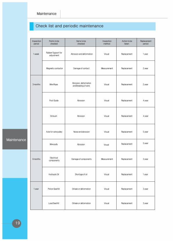
Check list and periodic maintenance
Safety Danger/warning/caution

1
1
2
3
6
7
8
9
1011
12
13 14
15
16
18
17
20
19
21
Introduction
Introduction
Names of each part are described

2
Front rolling jack
Platform (Slave)
Platform (Master)
Rear rolling jack
Lock rail
Post
Ramp
Ramp stopper
Rear support beam
Ramp stopper (option)
Ramp (option)
Introduction

3
Description
■ HL - 42L
Introduction
Introduction

Specification
4
HL - 42L
Main Lift: 4,500 Kg / JACK: 2,500 Kg
Main Lift: 1,740 mm / JACK: 455 mm
Main Lift: 174 mm / JACK: 235 mm
Main Lift: 1,566 mm
Main Lift: 40 ~ 60 sec. / JACK: 5 ~ 15 sec.
Main Lift: 30 ~ 50 sec. / JACK: 5 ~ 15 sec.
1ph : 2.5HP×4P×220V×60Hz / 3ph : 2HP×4P×220V,380V×60Hz
1,600 kg
3,425(W) × 2,215(H) × 5,860(L) mm
Introduction
Model Name
Capacity
Max. Height
Min. Height
Stroke
Lifting Time
Lowering Time
Standard Motor
Net Weight
Dimension
Warning before using the equipment
5
Precautions for safety
Safety
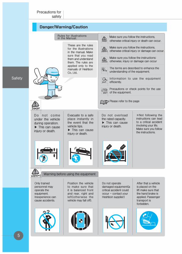
Danger/Warning/Caution
Make sure you follow the instructions,
otherwise critical injury or death can occur.
Make sure you follow the instructions, otherwise critical injury or damage can occur.
Make sure you follow the instructions; otherwise, injury or damage can occur
The terms are described to enhance the understanding of the equipment.
Information to use the equipment efficiently.
Precautions or check points for the use of the equipment.
Please refer to the page
Rules for illustrationsin the Manual.
These are the rules for the illustrations in the manual. Make sure that you read them and understand them. The rules are applied only to the manuals of Heshbon Co., Ltd..
Do not come under the vehicle during operation.▶ This can cause injury or death.
Evacuate to a safe place instantly in the event that the vehicle tips.▶ This can cause injury or death.
Do not overload the rated capacity.▶ This can cause injury or death.
※Not following the instructions can lead to a critical accident involving your life.Make sure you follow the instructions.
Only trained personnel may operate theequipment. Inexperience can cause accidents.
Position the vehicle to make sure that it is balanced front and rear, right and left(otherwise the vehicle may fall off).
Do not operate damaged equipment(a critical accident could occur - contact your Heshbon supplier)
After that a vehicle is placed on the lift make sure that the hand brake is applied. Passenger transport is forbidden.

Warning before using the equipmentWarning when operatingoperating
Warning while operating
Warning while operating
6
Safety
Allow no unauthorized persons in the work area.
Before lowering the lift, check that there are no obstructions under the vehicle or the lift arms.
When the vehicle is lifted, do not rock it as this may dislodge it.
Do not lift a vehicle using one pair of arms only.
To avoid injury, keep your feet clear of the arms and carriages.
Before going under the lift, make sure that the safety pawls are engaged.
To avoid beinge l e c t r o c u t e d , d isconnect the main power before opening the control panel.
Do not modify the control panel or the safety functions as this may impair their function.
Do not rock the vehicle when lifted. Do not use a high pressure cleaner as the vehicle lower part.
Read and fullyunderstand themanual before using the lift
Check the safety devices to see that they are clean and operable.
If the lift is idle for a long time, disconnect the main power supply. In the event of thunder storm. disconnect the main power supply.

Installation site
Installation site
7
Installation
Installation
Checklist before installing
The lift should be installed by skilled engineers either from Heshbon or from Heshbon's appointed representatives. Failure to observe this makes the lift warranty invalid. If the lift is to be moved to another site at a later date, it must be reinstalled by skilled engineers either from Heshbon or from Heshbon's appointed representatives.
Installation site
The site must be flat and horizontal. The floor must have minimum 150mm depth of reinforced concrete.
Surface load under the posts must be minimum 25N/㎟.
To maintain the warranty, the lift is intended for indoor installation only. In the event that it is installed outside it should be protected from snow and rain. Outdoor installation makes the warranty invalid.
Ambient temperature -10℃ to 50℃. Do not operate under freezing conditions.
Vehicle access to the lift must be safe and easy.
There must be a safe working distance of minimum 1m between the lift and the wall or any fixed object.
To ensure that the anchor is secure, the hole for an anchor bolt must be more than 2/3 of the bolt length.
Skilled engineers of Heshbon or its sale representative agency shall install the lift, otherwise a failure may occur.
-Hoist to be installed in dry location.-If hoist is installed in a Pit sufficient drainage should be allowed to keep hoist dry.-If hoist gets does get wet make sure all electrical wiring is dried before operation as could cause electric shock or damage to PCB.

8
1135
2215
1740
840
3425
2210
1030
2505
550
5860
4510
4435
Installation
Installation
Place of installation (Layout)
Checkpoints before selecting the place of installation
① Distance from the wall or any fixed object② Drive-on direction③ position of power post and slave posts④ Ceiling height
9
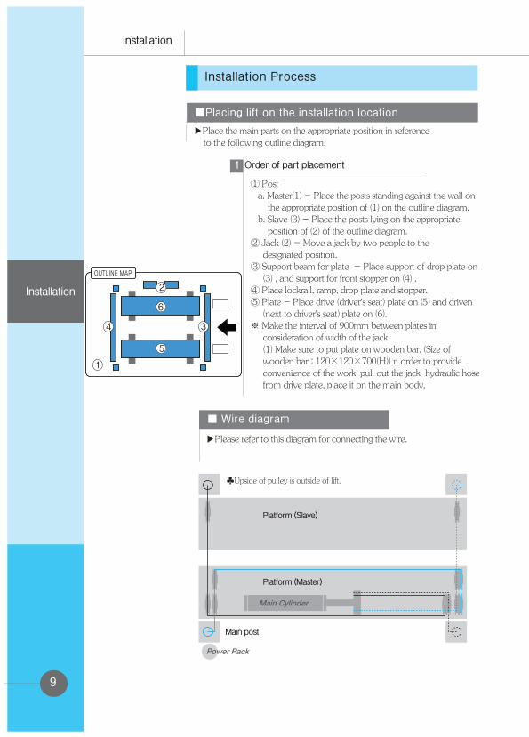
Installation Process
■Placing lift on the installation location
▶Place the main parts on the appropriate position in reference to the following outline diagram.
① Post a. Master(1) - Place the posts standing against the wall on the appropriate position of (1) on the outline diagram. b. Slave (3) - Place the posts lying on the appropriate position of (2) of the outline diagram.② Jack (2) - Move a jack by two people to the designated position. ③ Support beam for plate - Place support of drop plate on (3) , and support for front stopper on (4) . ④ Place lockrail, ramp, drop plate and stopper. ⑤ Plate - Place drive (driver's seat) plate on (5) and driven (next to driver's seat) plate on (6).※ Make the interval of 900mm between plates in consideration of width of the jack. (1) Make sure to put plate on wooden bar. (Size of wooden bar : 120×120×700(H)) n order to provide convenience of the work, pull out the jack hydraulic hose from drive plate, place it on the main body.
Order of part placement1
■ Wire diagram
▶Please refer to this diagram for connecting the wire.
Platform (Slave)
♣Upside of pulley is outside of lift.
Platform (Master)
Main post
Installation
Installation

10
Installation
Installation
▶Put the lower wire to the wire pulley of front support beam, and the upper wire to the wire pulley of rear support beam.
■Assembling post 1
▶Assemble the post with support beam
Put the lockrails to support beam for plate
Assembling lockrail1
Fasten two ① nuts (16mm). As shown in the figure, fasten the upper nut clockwise and the lower nut counterclockwise, maintaining the space to the lockrail for 55mm~60mm. Fasten two ② nuts (11.5mm), each to opposite direction, maintaining 2~3 threads (3mm) between the nuts. Fix ③ nut tight to the lockrail.
Assemble the lock rail 2 - (upside)2
Set up 4 posts, maintaining the space of 55~60mm between fixing plate of the top of the post and lockrail upper bracket.
Assemble the lock rail 3 - (4 post)3
Based on the lower part of the top hole of the lockrail (No.1) of the reference post (the highest post), measure the height of the remaining 3 posts (No. 2, 3 and 4), and measure the length. ※ It is required to match the heights of the 4 posts.
Make leveling of 4 post4
ⓐ 55~60mmⓑ 3mm

11
ⓐWater level ⓑWeight ⓒ Liner
1
2
-Put the weight and check the
verticality and level of 4 points.
■ Connection of oil pressure hose
Installation
Installation
Anchor bolt installation.(1)Drill a hole (d: hole depth) (2)Clean the inside of the hole (3)Put the anchor bolt into the hole and hammer in until it reaches the bottom of the hole(4)Tighten the bolt with a spanner. (a:35~45mm) - Torque : 125Nm/700kg.cm
After adjusts horizon, fix up the base platform using anchor.
Fixation of base (anchor)
After measure the horizontal status, lay down the lie. (in case of precise adjustment, use 'a'bolt.)
Adjustment the horizon of the base.
■Fixation horizon of the base.
▶After adjusts horizon of the product precisely, fix up using anchor bolt.

12
Installation
Installation
■ Connection of electronic line
■ Connection of oil pressure hose
▶Connect oil pressure hose by referring oil pressure line diagram. (Refer to part list oil pressure circuit)

13
Installation
Installation
■ Test operation
▶Operate ascent and descent 2~3 times under no load condition.
Before loading the lift, check the following points.
Inspect the lift everyday to operate the lift safely for a long time.
■ Switch operation
▶Check that the ascent and descent push buttons are working correctly.
■ Hydraulic check
▶Check if there are no hydraulic leaks from either cylinders, pipes, or hose joins.
■ Mechanical check
▶Check the tightness of all nuts, bolts, etc.
■ Exterior check
▶Check the exterior of the lift to ensure that there is no obvious damage.
■ Cleanliness
▶Check every day that the lift is clean and that the work area is clean and free from debris or obstructions.
Check points before operation

14
Operation
Operation
Check that the platforms are parked at floor level by using the descent button. Check that the auxiliary lift is at the down position.
Prior to use1
Check that the position of the righthand (movable) platform is suitable for the majority of the vehicles to be lifted. Fix the platform at this position with the bolts provided.
Prior to vehicle entry2
Operate the ascent button until platforms reach the chosen work height. park on the relevant ratchet holes.
Ascent3
Raise the auxiliary lift app. 50mm to allow adjustment of the rear extensions. Position the rubber blocks provided under the vehicle pick-up points. Again,operate the auxiliary lift ascent button to raise the vehicle to the required work height.
Auxiliary lift operation4
Perform the necessary repairs and/or maintenance on the vehicle. After completion,lower the auxiliary lift. As soon as the vehicle load is firmly on the platforms,stop the descent of the auxiliary lift, remove the rubber pads, push in the extensions, and lower to bottom position.Lower main lift.
Vehicle repair5
-After you drive into the lift, hold the side break.-After you drive into the lift, get out of the car.
Operation

15
■ Lubrication
▶Grease or oil should be applied every 2 or 3 months to the parts shown below.
▶Inject enough grease at shaft of auxiliary lift and roller. (2~3 month period)▶Auxiliary lift slide rubbing surface
Injecting grease1
▶Safety devices Check the area around the safety devices for cleanliness and any obstruction.
■ Cleanliness
▶Check the working area under and around the lift for cleanliness. Check visibly if any nuts or bolts are loose or missing. Replace and retighten as necessary.
▶Location of injecting lubricating oil - Paints the lubricant oil to the rubbing surface, base platform every 2~3 month.
Injecting oil2
Equipment maintenance and service
Operation
Maintenance

16
Maintenance
Maintenance
■ Emergency descent
How to descend the lift manually in emergency
1
① when a blackout or the hydraulic circuit failure occurs
② When the lift cannot descend as specified in the troubleshooting
① Remove any object under the lift.
② Turn off the main power switch and panel power switch.
③ Manually release the locker In case of locking state, releases the locker while another hydraulic device is lifting the
locker 30 mm high. . ④ After taking to pieces in manually, put the supports between lockers.
This situation is potentially very dangerous.This operation should not be undertaken by unskilled staff. Therefore, if in any doubt, call your lift supplier immediately for after sales service.
Preparation before operating
It is necessary
Operation procedure of manual descent *Remove the cover of the powerpack. Remove the solenoid valve hexagon cap (19mm) in the middle of the pump manifold.Turn the emergency cock lever (a) very slowly anti-clockwise. Too much movement will increase descent speed too much.
Turn the emergency cock lever very slowly to ensure that descent speed is slow and safe, especially if there is a vehicle on the lift.
Steps after completing the operationTurn the lever clockwise and lock it securely when the lift reaches bottom position.Replace and refit the hexagon cap. Request after sales service to check the lift.
Release of the locker
Release of the locker

17
Open the control panel and install a pressure gauge in the pump manifold as shown. The pressure adjusting screw (a) is sealed by the factory. Remove the seal and adjust the pressure with a screwdriver. This should be done while pressing the ascent button at the same time.
The pressure is set by the factory. The lift may be damaged if the operator increases the pressure.If the equipment does not lift the rated capacity,contact your lift supplier for engineer assistance.
Powerpack pressure2
Information for the authorized service engineer only
ⓐ Cap of the oil tank
ⓑ Oil tank
ⓒ Cover of the hydraulic unit
ⓓ Oil nozzle cap
ⓔ Pump filter
① Oil injection② Oil discharge
Oil change3
① Remove the cover of the hydraulic unit.
② Remove the oil filter cap and dipstick.Carefully remove the oil drain plug and allow the oil to discharge into a suitable container.
③ Refit the drain plug and tighten
④ Refill the oil tank with new oil.
⑤ Check with the dipstick that the level is correct,raise and lower the lift and recheck that the level is still correct.
Oil should be changed 3 months after installation and thereafter annually.
At the annual oil change, after having drained the oil tank, remove the oil tank from the pump and check the condition of the pump filter.Clean or replace as necessary.Replace tank and follow the above procedure.
Oil change procedure
Maintenance
Maintenance

18
Maintenance
Maintenance
Trouble Shooting
19
Check list and periodic maintenance
Maintenance
Maintenance


HESHBON CO.,LTD. 673-52, GYEONGSEO-DONG, SEO-GU, INCHEON, 404-170 KOREATEL:+82-32-585-3570(Int’l trading) / FAX: +82-32-585-3535 http://www.heshbon.com / e-mail:[email protected]