hm17 8vn1 gis mit ncit eng - amazon web services · 8dn9 8dq1 420 kv 550 kv 80 ka 63 ka 6300 a 5000...
TRANSCRIPT

siemens.com/energy-management© Siemens AG 2017
Gas-Insulated SwitchgearType 8VN1 blue GIS up to 145 kV, 40 kA, 3150 A

© Siemens AG 2017
April 24 – 28, 2017Page 2 Siemens.com/hm17
8VN1 blue GIS up to 145 kV
Table of content
Gas-insulated switchgear
Product portfolio 72.5 – 550 kV
Vacuum interrupters for switching
Vacuum interrupter technology
History and production technology
Clean air for insulation
Clean air insulation technology
8VN1 blue GIS up to 145 kV
Technical data
Modular structure
Essentials

© Siemens AG 2017
April 24 – 28, 2017Page 3 Siemens.com/hm17
8VN1 blue GIS up to 145 kV
GIS Product Portfolio 72.5 kV – 550 kV
8DQ18DN9
420 kV 550 kV
80 kA 63 kA
6300 A 5000 A
245 kV
50 kA
4000 A
Rated voltage up to:
Rated short
circuit-breaking current
Rated current busbar up to:
Product line
Solution
5000 A 5000 A4000 ARated current feeder up to:
420 kV
(245 kV)
63 kA
(80/90 kA)
6300 A
5000 A
72.5 kV
up to: 25 kA
-
1250 A
8VM1
Interrupter technology
Insulation medium
8DN8
40 kA
3150 A
3150 A
Self-compressions principle
SF6
145 kV 170 kV
63 kA
4000 A
4000 A
145 kV
40 kA
3150 A
3150 A
Vacuum
Clean air
8VN1

© Siemens AG 2017
April 24 – 28, 2017Page 4 Siemens.com/hm17
8VN1 blue GIS up to 145 kV
Vacuum interrupter technology - Customer value
High reliability
due to the hermetically tight vacuum interrupter,
eliminating any influence of decomposition products
High performance
Perfect for frequent switching applications: High number of short-circuit interruptions with
excellent interrupting performance at rated nominal current and rated short-circuit currents
throughout life-time of the vacuum circuit-breaker
Perfect for low temperature
No liquefaction of switching medium
No maintenance
Maintenance free due to sealed for life technology; no spare part costs
No CO2e emissions
Switching media (vacuum) with GWP=0;
no CO2e emissions during operation, maintenance or recycling
CO2 NEUTRAL
For more than 40 years successful operational experience in medium-voltage, since 2010 in
high-voltage

© Siemens AG 2017
April 24 – 28, 2017Page 5 Siemens.com/hm17
8VN1 blue GIS up to 145 kVVacuum interrupter Development of product / production technology
1‘0
2‘0
3‘0
1970 1980 1990 2000
million
pieces
2010
one-shot brazing technologymany-fold pumping technology
1971
First serial manufacturing
of vacuum interrupters for
contactors.
• More than 40 years of operational experience in the
field of medium voltage applications
• More than 5.5 million vacuum interrupters delivered
2020
4‘0
5‘0
2010
Introduction
of prototypes
for 72.5 kV
2016
Introduction of 145 kV
portfolio with
vacuum interrupter
for up to 72.5 kV
and up to 145 kV
High-
Voltage
goes
Vacuum!

© Siemens AG 2017
April 24 – 28, 2017Page 6 Siemens.com/hm17
8VN1 blue GIS up to 145 kV
Production of vacuum interrupters
Assembly under clean room conditions
special clothing for the staff
working documents only in digital form
particle cleaning of all articles entering
the clean room
ensures a consistent high quality
standard.
Clean room conditions

© Siemens AG 2017
April 24 – 28, 2017Page 7 Siemens.com/hm17
8VN1 blue GIS up to 145 kV
Production of vacuum interrupters
The brazing furnace ensures that its
complete volume is evacuated and the
vacuum interrupters are exposed to a
pre-defined temperature profile.
Depending on loading, one cycle can
require up to 20 hours.
The fully automatic system guarantees
the vacuum interrupters to be
“sealed for life”.
One-shot brazing technology under
clean room conditions

© Siemens AG 2017
April 24 – 28, 2017Page 8 Siemens.com/hm17
8VN1 blue GIS up to 145 kV
Production of vacuum interrupters
With help of x-ray based testing,
positions and completeness of internal
parts as well as brazed joints can be
exactly ascertained.
This intermediate inspection grants for
continuously high quality and longevity.
X-ray based quality inspection

© Siemens AG 2017
April 24 – 28, 2017Page 9 Siemens.com/hm17
8VN1 blue GIS up to 145 kV
Clean air insulation technology - Customer value
No Global Warming Potential: GWP = 0 (Potencial de calentamiento Global) (SF6 GWP 276)
No Ozone Depletion Potential: ODP = 0 (Potencial de agotamiento de Ozono)
Non-toxic (no known toxicological effects: LC50, TLV-TWA, CMR)
Non-flammable
High stability
Low boiling point and no liquefaction of insulation medium
Clean air with well-known and proven material compatibilities
F-gas free insulation with lowest requirements on training, transport, installation, operation, reporting and recycling
C-gas free with no risk of C-decomposition
No documentation and reporting duties for clean air gas
No CO2 compensation costs or risk of future tax or compensation
No gas recycling required
Clean air is a composition of 80% N2 and 20% O2, cleaned and free from humidity (Synthetic air)

© Siemens AG 2017
April 24 – 28, 2017Page 10 Siemens.com/hm17
8VN1 blue GIS up to 145 kV
GIS with vacuum circuit-breaker and clean air technology
40 years of experience – 5.5 million vacuum interrupters delivered
Perfect for frequent switching and low temperature applications
Completely type-tested according to latest international standards
Lowest operation and maintenance costs:
Sealed for life interrupter unit; no gas handling during lifetime required
No reporting or emission costs during operation and recycling:
No SF6- or F-gas tax or future risk, No CO2e emission compensation or future risk
No F-gas documentation or reporting costs; no risk of F-gas gas recycling costs
CO2 NEUTRAL
Values for customers and environmental sustainability

© Siemens AG 2017
April 24 – 28, 2017Page 11 Siemens.com/hm17
8VN1 blue GIS up to 145 kV
Technical data (with Conventional Instrument Transformer)
Vacuum circuit-breaker
Insulation medium clean air
Switchgear type 8VN1
Rated voltage up to 145 kV
Rated frequency 50 / 60 Hz
Rated short-duration power-frequency withstand voltage (1 min) up to 275 kV
Rated lightning impulse withstand voltage (1.2 / 50 µs) up to 650 kV
Rated normal current – busbar up to 3150 A
Rated normal current – feeder up to 3150 A
Rated short-circuit breaking current up to 40 kA
Rated peak withstand current up to 108 kA
Rated short-time withstand current (up to 3 s) up to 40 kA
Leakage rate per year and gas compartment (type-tested) < 0.1 %
Driving mechanism of circuit-breaker stored-energy spring
Rated operating sequenceO-0.3 s-CO-3 min-CO
CO-15 s-CO
Interrupter technology Vacuum
Insulation medium Clean air
Weight of SF6 or other flourinated greenhouse gases 0 kg
GWP Global Warming Potential 0
CO2 equivalent 0 kg
Rated filling pressure 0,77 MPa abs
Bay width common pole drive 1000 mm
Bay hight, depth (depending on bay arrangement) 3200 mm x 5500 mm
Bay weight (depending on bay arrangement) 4.7 t
Ambient temperature range -50 ºC up to +55 ºC
Installation indoor / outdoor
First major inspection > 25 years
Expected lifetime > 50 years
Standards IEC / IEEE
Other values on request
VTCT
© Siemens AG 2017
April 24 – 28, 2017Page 12 Siemens.com/hm17
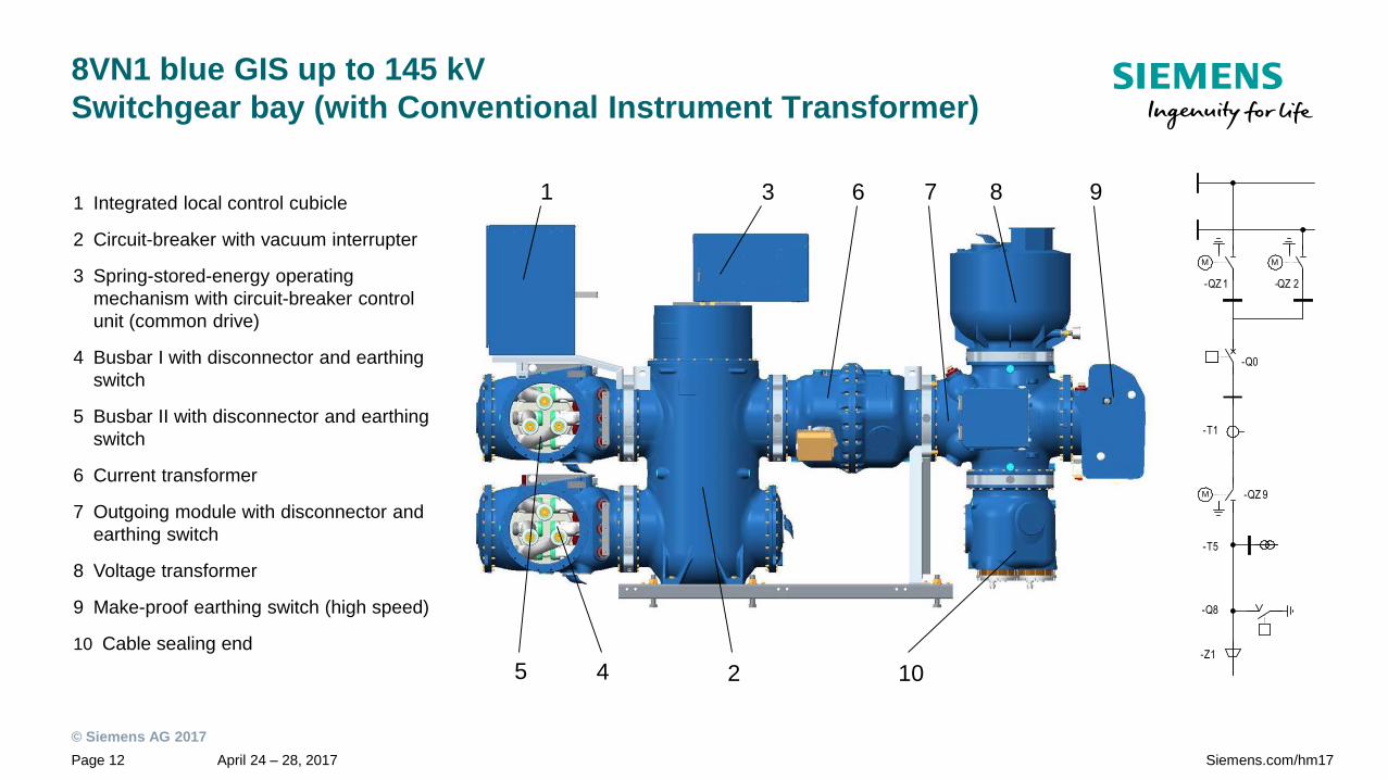
8VN1 blue GIS up to 145 kV
Switchgear bay (with Conventional Instrument Transformer)
1 Integrated local control cubicle
2 Circuit-breaker with vacuum interrupter
3 Spring-stored-energy operating
mechanism with circuit-breaker control
unit (common drive)
4 Busbar I with disconnector and earthing
switch
5 Busbar II with disconnector and earthing
switch
6 Current transformer
7 Outgoing module with disconnector and
earthing switch
8 Voltage transformer
9 Make-proof earthing switch (high speed)
10 Cable sealing end
-Q0
-T1
-Z1
-T5
-QZ 1 -QZ 2
M
-Q8
-QZ 9M
M
1 6
245
3 8 97
10
© Siemens AG 2017
April 24 – 28, 2017Page 13 Siemens.com/hm17
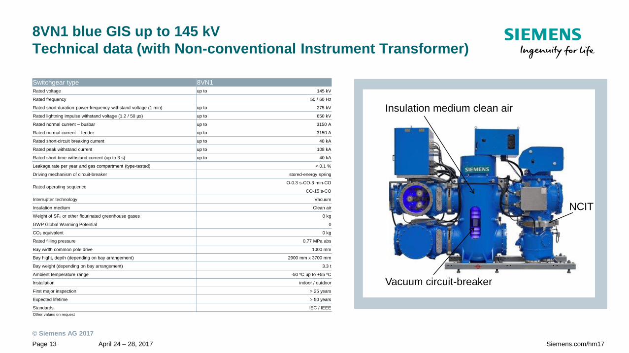
8VN1 blue GIS up to 145 kV
Technical data (with Non-conventional Instrument Transformer)
Switchgear type 8VN1
Rated voltage up to 145 kV
Rated frequency 50 / 60 Hz
Rated short-duration power-frequency withstand voltage (1 min) up to 275 kV
Rated lightning impulse withstand voltage (1.2 / 50 µs) up to 650 kV
Rated normal current – busbar up to 3150 A
Rated normal current – feeder up to 3150 A
Rated short-circuit breaking current up to 40 kA
Rated peak withstand current up to 108 kA
Rated short-time withstand current (up to 3 s) up to 40 kA
Leakage rate per year and gas compartment (type-tested) < 0.1 %
Driving mechanism of circuit-breaker stored-energy spring
Rated operating sequenceO-0.3 s-CO-3 min-CO
CO-15 s-CO
Interrupter technology Vacuum
Insulation medium Clean air
Weight of SF6 or other flourinated greenhouse gases 0 kg
GWP Global Warming Potential 0
CO2 equivalent 0 kg
Rated filling pressure 0,77 MPa abs
Bay width common pole drive 1000 mm
Bay hight, depth (depending on bay arrangement) 2900 mm x 3700 mm
Bay weight (depending on bay arrangement) 3.3 t
Ambient temperature range -50 ºC up to +55 ºC
Installation indoor / outdoor
First major inspection > 25 years
Expected lifetime > 50 years
Standards IEC / IEEE
Other values on request
Vacuum circuit-breaker
Insulation medium clean air
NCIT

© Siemens AG 2017
April 24 – 28, 2017Page 14 Siemens.com/hm17
8VN1 blue GIS up to 145 kV
Switchgear bay (with Non-conventional Instrument Transformer)
1 Integrated local control cubicle
2 Circuit-breaker with vacuum interrupter
3 Spring-stored-energy operating mechanism with
circuit-breaker control unit (common drive)
4 Busbar I with disconnector and earthing switch
5 Busbar II with disconnector and earthing switch
6 Non-Conventional Instrument Transformers
(NCIT)
7 Outgoing module with disconnector and
earthing switch
8 Make-proof earthing switch (high speed)
9 Cable sealing end
1
6245
3 87
9
-Q0
NCIT - T 1 / - T5
-Z1
-QZ 1 -QZ 2
M
-Q8
-QZ 9M
M

© Siemens AG 2017
April 24 – 28, 2017Page 15 Siemens.com/hm17
8VN1 blue GIS up to 145 kV
Modular structure
Cable Module
Outdoor Bushing
Extension Modules
Splitting Module 1/3-phase
three-phase
Earthing Switch
Disconnector / EarthingSwitch (Cross Module)
Surge Arrester
Current Transformer
Voltage Transformer
Vacuum Circuit Breaker
Switchgear Bay
(NCIT) Non-ConventionalInstrument Transformers
© Siemens AG 2017
April 24 – 28, 2017Page 16 Siemens.com/hm17
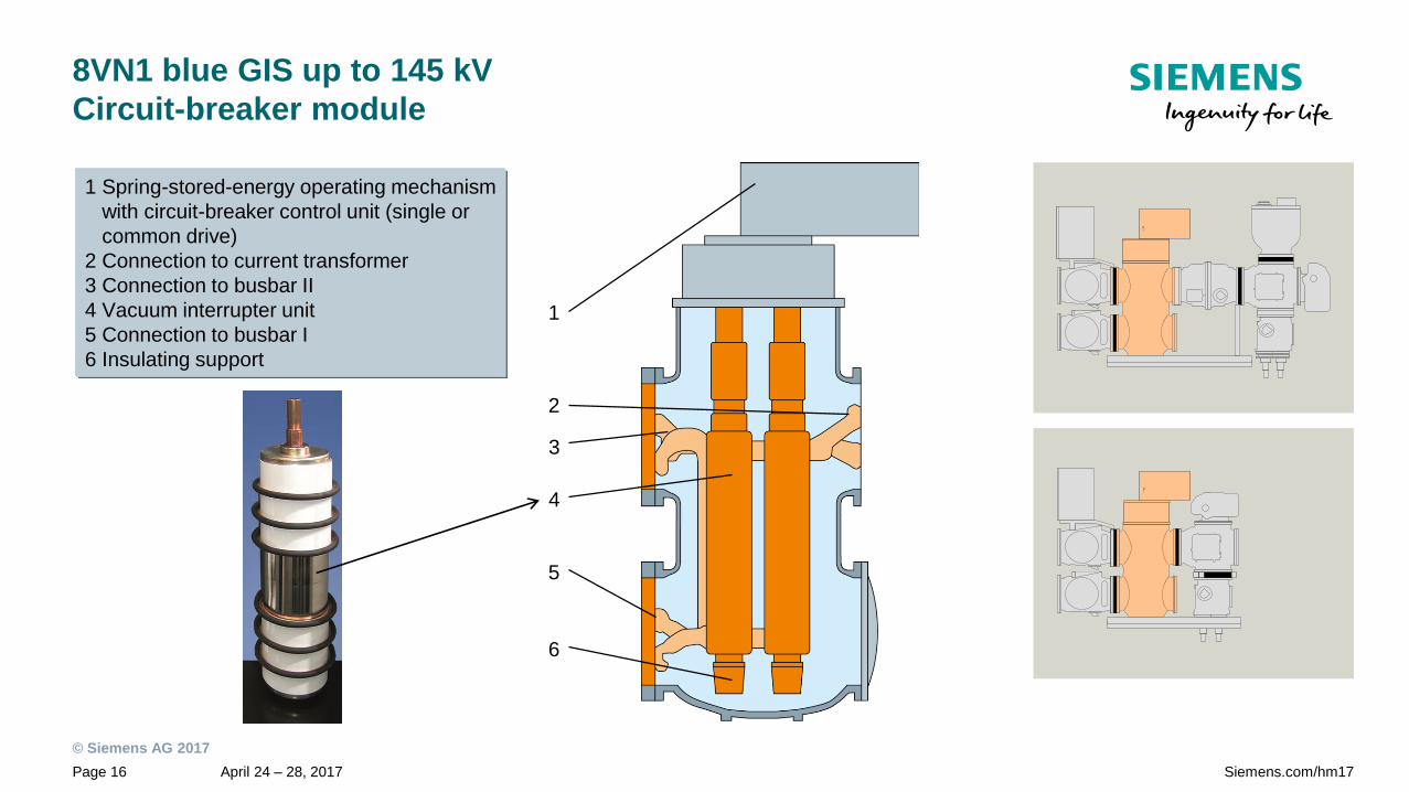
8VN1 blue GIS up to 145 kV
Circuit-breaker module
1 Spring-stored-energy operating mechanism
with circuit-breaker control unit (single or
common drive)
2 Connection to current transformer
3 Connection to busbar II
4 Vacuum interrupter unit
5 Connection to busbar I
6 Insulating support
1
2
3
4
5
6

© Siemens AG 2017
April 24 – 28, 2017Page 17 Siemens.com/hm17
8VN1 blue GIS up to 145 kV
Spring operated mechanism
“off” position(Closing spring loaded)
On
Off
1 Closing release2 Cam plate 3 Coupling linkage4 Operating rod 5 Closing spring connecting rod 6 Opening spring connecting rod7 Closing spring8 Hand-wound mechanism9 Charging mechanism
10 Charging shaft11 Roller lever12 Closing damper13 Operating shaft14 Opening damper15 Opening release16 Mechanism housing17 Opening spring

© Siemens AG 2017
April 24 – 28, 2017Page 18 Siemens.com/hm17
8VN1 blue GIS up to 145 kVConventional /Non-Conventional Instrument Transformer-Technology
Inductive Voltage Transformer (VT) Inductive Current Transformer (CT)
Conventional Instrument Transformer Technology
Non-conventional Instrument Transformer (NCIT) Technology
1 x Electric Field Probe
for Voltage Measurement
2 x Rogowski Coils for Current
Measurement (redundant)
Cast resin partition with integrated
voltage and current sensors
+
+ = 2.9
m
3.7 m
3.2
m
5.5 m
© Siemens AG 2017
April 24 – 28, 2017Page 19 Siemens.com/hm17
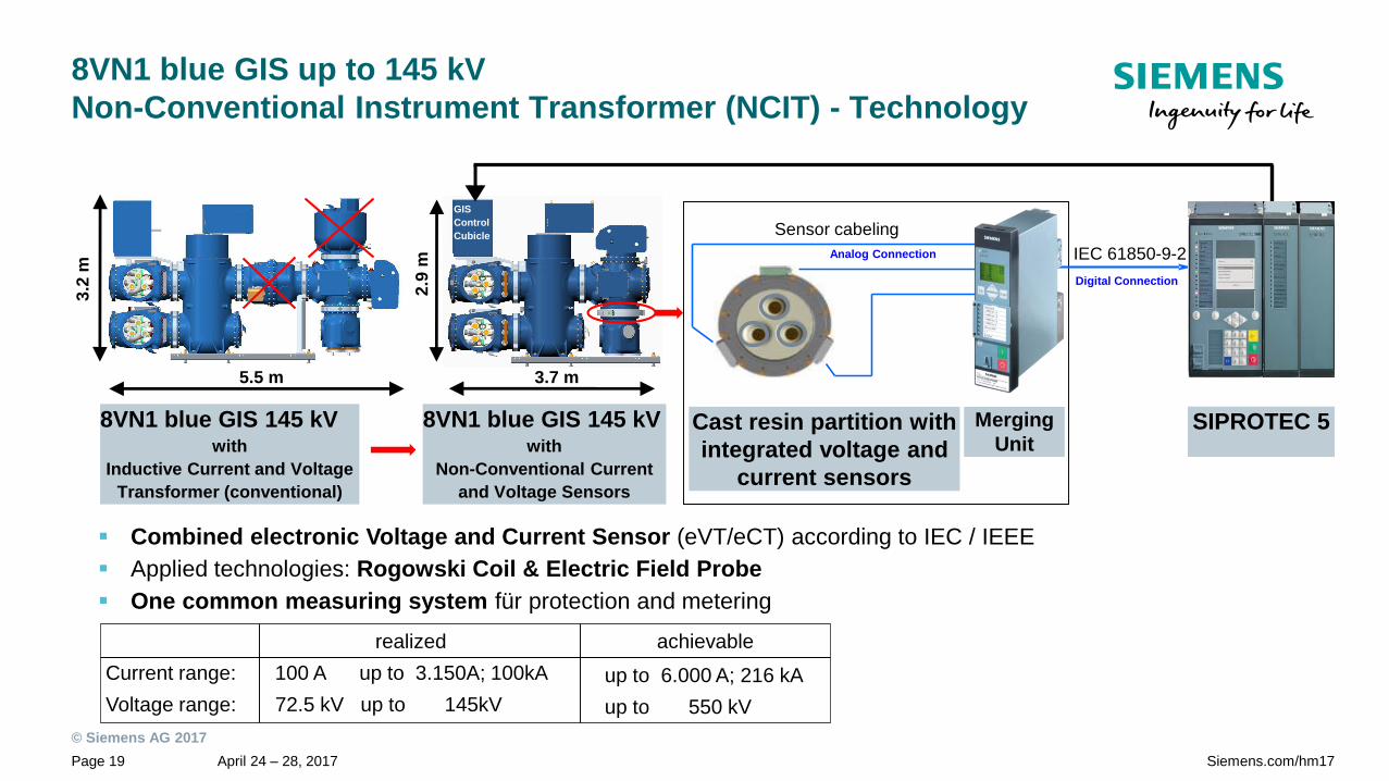
8VN1 blue GIS up to 145 kV
Non-Conventional Instrument Transformer (NCIT) - Technology
SIPROTEC 5Merging
Unit
IEC 61850-9-2
Sensor cabeling
Analog Connection
Digital Connection
Cast resin partition with
integrated voltage and
current sensors
8VN1 blue GIS 145 kV with
Inductive Current and Voltage
Transformer (conventional)
Combined electronic Voltage and Current Sensor (eVT/eCT) according to IEC / IEEE
Applied technologies: Rogowski Coil & Electric Field Probe
One common measuring system für protection and metering
3.2
m
2.9
m
5.5 m 3.7 m
8VN1 blue GIS 145 kV with
Non-Conventional Current
and Voltage Sensors
GIS
Control
Cubicle
realized achievable
Current range: 100 A up to 3.150A; 100kA
Voltage range: 72.5 kV up to 145kV
up to 6.000 A; 216 kA
up to 550 kV
© Siemens AG 2017
April 24 – 28, 2017Page 20 Siemens.com/hm17
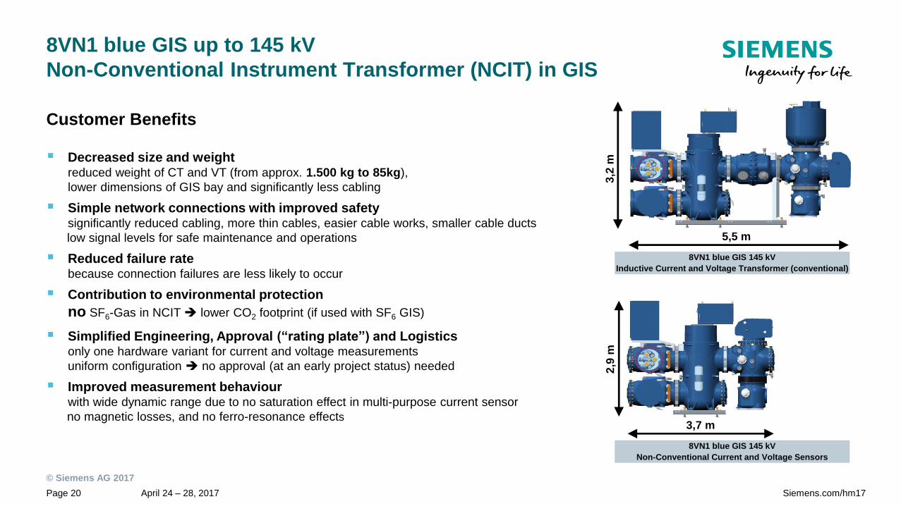
8VN1 blue GIS up to 145 kV
Non-Conventional Instrument Transformer (NCIT) in GIS
Decreased size and weightreduced weight of CT and VT (from approx. 1.500 kg to 85kg),
lower dimensions of GIS bay and significantly less cabling
Simple network connections with improved safetysignificantly reduced cabling, more thin cables, easier cable works, smaller cable ducts
low signal levels for safe maintenance and operations
Reduced failure ratebecause connection failures are less likely to occur
Contribution to environmental protection
no SF6-Gas in NCIT lower CO2 footprint (if used with SF6 GIS)
Simplified Engineering, Approval (“rating plate”) and Logisticsonly one hardware variant for current and voltage measurements
uniform configuration no approval (at an early project status) needed
Improved measurement behaviourwith wide dynamic range due to no saturation effect in multi-purpose current sensor
no magnetic losses, and no ferro-resonance effects
Customer Benefits
8VN1 blue GIS 145 kV
Inductive Current and Voltage Transformer (conventional)
8VN1 blue GIS 145 kV
Non-Conventional Current and Voltage Sensors
3,7 m
2,9
m
5,5 m
3,2
m

© Siemens AG 2017
April 24 – 28, 2017Page 21 Siemens.com/hm17
8VN1 blue GIS up to 145 kV
Essentials at a glance
Environmental-friendly
The 8VN1 uses clean air as insulation medium. Clean air is a composition of 80% N2
and 20% O2, cleaned and free from humidity (technical air). The clean air Global
Warming Potential GWP is 0. Clean air is and will not be part of the EU-F-gas regulation.
Experience
The 8VN1 is based on vacuum interrupter technology with more than 40 years
successful operational experience in the field of medium-voltage and since 2010 in high-
voltage.
RobustnessThe fixed bay concept of the 8VN1 leads to an improved seismic resistance of 0.5g (IEC
62271-207) without additional measures.
Indoor and outdoor applicationThe 8VN1 offers the well-known and proven modular design and can be used for indoor
and outdoor applications from -50°C to +55°C at 50 / 60 Hz.
Highest quality and
reliability
Compliance with the extended mechanical endurance class M2.
10,000 mechanical operations (CB, DS).
Adapter modules 8VN1 is compatible with all previously installed Siemens GIS of the same voltage level.

© Siemens AG 2017
April 24 – 28, 2017Page 22 Siemens.com/hm17
8VN1 blue GIS up to 145 kV
Contact
Siemens AG
Energy Management
High-Voltage Products
Gas-Insulated-Switchgear
Customer Support Center
Phone: +49 180 524 70 – 00
E-mail: support.energy.com
siemens.com/hm17