hm7042-5 triple power supply user manual
TRANSCRIPT

HM7042-5Triple Power Supply User Manual
General remarks regarding the CE markingHAMEG measuring instruments comply with the EMI norms. Our tests for conformity are based upon the relevant norms. Whenever different maximum limits are optional HAMEG will select the most stringent ones. As regards emissions class 1B limits for small business will be applied. As regards susceptability the limits for industrial environments will be applied. All connecting cables will in uence emissions as well as suscepta ility considera ly. The cables used will differ substantially depending on the application. During practical operation the following guidelines should be absolutely observed in order to minimize EMI:
1. Data connectionsMeasuring instruments may only be connected to external associated equipment (printers, computers etc.) by usingwell shielded cables. Unless shorter lengths are prescribed a maximum length of 3 m must not be exceeded for all data interconnections (input, output, signals, control). In case an instrument interface would allow connecting several cablesonly one may be connected. In general, data connectionsshould be made using double-shielded cables. For IEEE-bus purposes the double screened cable HZ72 from is suitable.
2. Signal connectionsIn general, all connections between a measuring instrumentand the device under test should be made as short aspossible. Unless a shorter length is prescribed a maximum length of 3 m must not be exceeded, also, such connections must not leave the premises. All signal connections must be shielded (e.g. coax such as RG58/U). With signal generators double-shielded cables are mandatory. It is especiallyimportant to establish good ground connections.
3. External influencesIn the vicinity of strong magnetic or/and electric eldseven a careful measuring set-up may not e suf cientto guard against the intrusion of undesired signals. Thiswill not cause destruction or malfunction of HAMEGinstruments, however, small deviations from the guaranteed speci cations may occur under such conditions.
G e n e r a l r e m a r k s r e g a r d i n g t h e C E m a r k i n g
DECLARATION OF CONFORMITY
Manufacturer:HAMEG Instruments GmbHIndustriestraße 6 · D-63533 Mainhausen
The HAMEG Instruments GmbH herewith declares conformity of the product:
Product name: Triple Power SupplyType: HM7042-5
complies with the provisions of the Directive of the Council of the European Union on the approximation of the laws of the Member States
relating to electrical equipment for use within defined voltage limits(2006/95/EC) [LVD]
relating to electromagnetic compatibility (2004/108/EC) [EMCD]relating to restriction of the use of hazardous substances in electrical and electronic equipment (2011/65/EC) [RoHS].
Conformity with LVD and EMCD is proven by compliance with the following standards:
EN 61010-1: 04/2015EN 61326-1: 07/2013EN 55011: 11/2014EN 61000-3-2: 03/2015EN 61000-3-3: 03/2014EN 61000-4-2: 12/2009EN 61000-4-3: 04/2011EN 61000-4-4: 04/2013EN 61000-4-5: 03/2015EN 61000-4-6: 08/2014EN 61000-4-11: 02/2005 EN 61000-6-3: 11/2012
For the assessment of electromagnetic compatibility, the limits of radio interference for Class B equipment as well as the immunity to interference for operation in industry have been used as a basis.
Date: 8.6.2015
Signature:
Holger Asmussen General Manager
北京海洋兴业科技股份有限公司(证券代码:839145) www.hyxyyq.com
G e n e r a l r e m a r k s r e g a r d i n g t h e C E m a r k i n g
Content Ta b l e o f c o n t e n t
General remarks regarding the CE marking 16
Technical Data 18
1 Important hints 201.1 Symbols 201.2 Unpacking 201.3 Positioning 201.4 Transport / Storage 201.5 Safety instructions 201.6 Proper operating conditions 201.7 Warranty and Repair 211.8 Maintenance 211.9 Mains voltage and Changing the line fuse 21
2 Operating Controls 22
3 Basics of Power Supplies 233.1 Linear power supplies 233.2 Switched-mode Power Supplies (SMPS) 233.3 Parallel and Series Operation 233.4 Current Limit 243.5 Electronic Fuse 24
4 Concept of the HM7042-5 254.1 Output power of the HM7042-5 254.2 Switching the display on/off 25
5 Introduction to the operation 255.1 First time operation 255.2 Turning on the HM7042-5 25
6 Operating controls and displays 266.1 Kanal I + III 266.2 Kanal II 266.3 Current Limiting 276.4 Electronic Fuse 27
北京海洋兴业科技股份有限公司(证券代码:839145) www.hyxyyq.com
H M 7 0 4 2 - 5
Tech
nica
l Dat
a
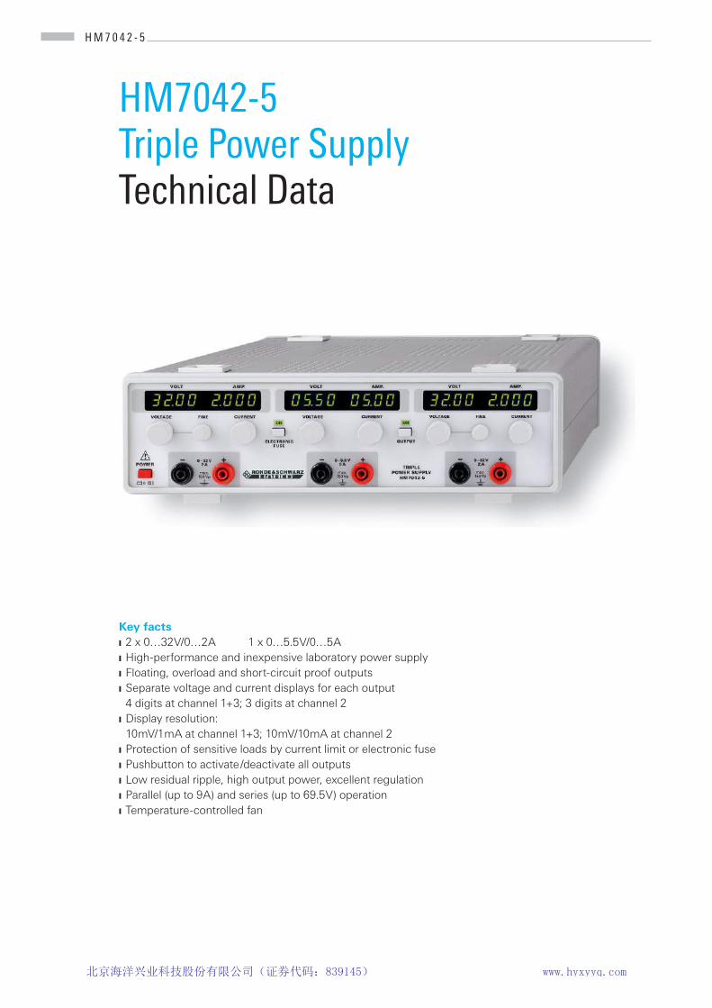
Key facts2 x 0…32 V/0…2 A 1 x 0…5.5 V/0…5 AHigh-performance and inexpensive laboratory power supplyFloating, overload and short-circuit proof outputs Separate voltage and current displays for each output4 digits at channel 1+3; 3 digits at channel 2 Display resolution:10 mV/1 mA at channel 1+3; 10 mV/10 mA at channel 2Protection of sensitive loads by current limit or electronic fusePushbutton to activate /deactivate all outputsLow residual ripple, high output power, excellent regulationParallel (up to 9 A) and series (up to 69.5 V) operationTemperature-controlled fan
PD 5
210.
8608
.32
- 02.
01
HM7042-5Triple Power Supply Technical Data
北京海洋兴业科技股份有限公司(证券代码:839145) www.hyxyyq.com
H M 7 0 4 2 - 5 Te c h n i c a l D a t a
Technical Data
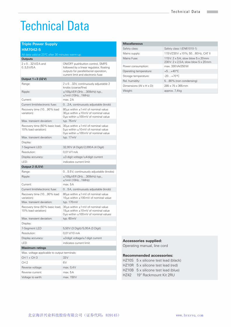
Accessories supplied: Operating manual, line cord
Recommended accessories:HZ10S 5 x silicone test lead (black)HZ10R 5 x silicone test lead (red)HZ10B 5 x silicone test lead (blue)HZ42 19" Rackmount Kit 2RU
Triple Power Supply
HM7042-5All data valid at 23 °C after 30 minutes warm-up.
Outputs
2 x 0…32 V/2 A and 0..5,5 V/5 A
ON/OFF pushbutton control, SMPS followed by a linear regulator, floating outputs for parallel/serial operation, current limit and electronic fuse
Output 1 + 3 (32 V)
Range: 2 x 0…32V, continuously adjustable 2 knobs (coarse / fine)
Ripple: ≤100µVEff (3Hz....300kHz) typ.,≤1mV (10Hz...1MHz)
Current: max. 2 A
Current limit/electronic fuse: 0…2 A, continuously adjustable (knob)
Recovery time (10…90 % load variation):
80 µs within ±1 mV of nominal value 30 µs within ±10 mV of nominal value 0 µs within ±100 mV of nominal value
Max. transient deviation: typ. 75 mV
Recovery time (50 % basic load, 10 % load variation):
30 µs within ±1 mV of nominal value5 µs within ±10 mV of nominal value0 µs within ±100 mV of nominal value
Max. transient deviation: typ. 17 mV
Display:
7-Segment LED: 32,00 V (4 Digit) / 2,000 A (4 Digit)
Resolution: 0,01 V/1 mA
Display accuracy: ±3 digit voltage / ±4 digit current
LED: indicates current limit
Output 2 (5,5 V)
Range: 0…5.5 V, continuously adjustable (knobs)
Ripple: ≤100µVEff (3Hz....300kHz) typ.,≤1mV (10Hz...1MHz)
Current: max. 5 A
Current limit/electronic fuse: 0…5 A, continuously adjustable (knob)
Recovery time (10…90 % load variation):
80 µs within ±1 mV of nominal value10 µs within ±100 mV of nominal value
Max. transient deviation: typ. 170 mV
Recovery time (50 % basic load, 10 % load variation):
30 µs within ±1 mV of nominal value15 µs within ±10 mV of nominal value0 µs within ±100 mV of nominal valuee
Max. transient deviation: typ. 60 mV
Display:
7-Segment LED 5,50 V (3 Digit) / 5,00 A (3 Digit)
Resolution: 0,01 V/10 mA
Display accuracy: ±3 digit voltage/±1 digit current
LED indicates current limit
Maximum ratings
Max. voltage applicable to output terminals:
CH 1 + CH 3 33 V
CH 2 6 V
Reverse voltage: max. 0,4 V
Reverse current: max. 5 A
Voltage to earth: max. 150 V
Miscellaneous
Safety class: Safety class I (EN61010-1)
Mains supply: 115 V/230 V ±10 %; 50…60 Hz, CAT II
Mains Fuse: 115 V: 2 x 5 A; slow blow 5 x 20 mm 230 V: 2 x 2,5 A; slow blow 5 x 20 mm
Power consumption: max. 330 VA/250 W
Operating temperature: +5…+40 °C
Storage temperature: -20…+70 °C
Rel. humidity: 5…80 % (non condensing)
Dimensions (W x H x D): 285 x 75 x 365 mm
Weight: approx. 7,4 kg
北京海洋兴业科技股份有限公司(证券代码:839145) www.hyxyyq.com
1 Important hints
(1) (2) (3)
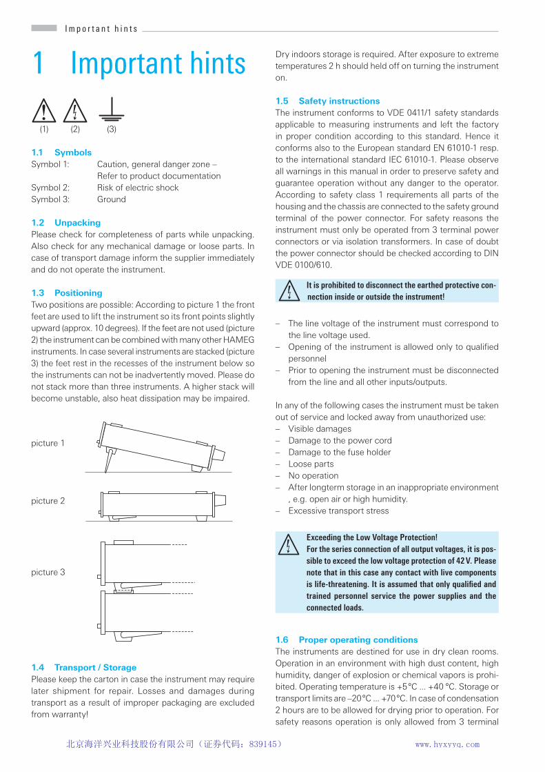
1.1 SymbolsSymbol 1: Caution, general danger zone –
Refer to product documentationSymbol 2: Risk of electric shock Symbol 3: Ground
1.2 UnpackingPlease check for completeness of parts while unpacking. Also check for any mechanical damage or loose parts. In case of transport damage inform the supplier immediately and do not operate the instrument.
1.3 PositioningTwo positions are possible: According to picture 1 the front feet are used to lift the instrument so its front points slightly upward (approx. 10 degrees). If the feet are not used (picture 2) the instrument can be combined with many other HAMEG instruments. In case several instruments are stacked (picture3) the feet rest in the recesses of the instrument below sothe instruments can not be inadvertently moved. Please donot stack more than three instruments. A higher stack willbecome unstable, also heat dissipation may be impaired.
1.4 Transport / StoragePlease keep the carton in case the instrument may require later shipment for repair. Losses and damages during transport as a result of improper packaging are excluded from warranty!
picture 3
picture 2
picture 1
Dry indoors storage is required. After exposure to extreme temperatures 2 h should held off on turning the instrument on.
1.5 Safety instructionsThe instrument conforms to VDE 0411/1 safety standards applicable to measuring instruments and left the factory in proper condition according to this standard. Hence it conforms also to the European standard EN 61010-1 resp. to the international standard IEC 61010-1. Please observe all warnings in this manual in order to preserve safety and guarantee operation without any danger to the operator. According to safety class 1 requirements all parts of the housing and the chassis are connected to the safety ground terminal of the power connector. For safety reasons the instrument must only be operated from 3 terminal power connectors or via isolation transformers. In case of doubt the power connector should be checked according to DIN VDE 0100/610.
– The line voltage of the instrument must correspond tothe line voltage used.
pening of the instrument is allowed only to uali edpersonnel
– Prior to opening the instrument must be disconnectedfrom the line and all other inputs/outputs.
In any of the following cases the instrument must be taken out of service and locked away from unauthorized use:– Visible damages– Damage to the power cord– Damage to the fuse holder– Loose parts– No operation– After longterm storage in an inappropriate environment
, e.g. open air or high humidity.– Excessive transport stress
1.6 Proper operating conditionsThe instruments are destined for use in dry clean rooms. Operation in an environment with high dust content, high humidity, danger of explosion or chemical vapors is prohi-bited. Operating temperature is +5 °C ... +40 °C. Storage or transport limits are –20 °C ... +70 °C. In case of condensation 2 hours are to be allowed for drying prior to operation. For safety reasons operation is only allowed from 3 terminal
It is prohibited to disconnect the earthed protective con-nection inside or outside the instrument!
Exceeding the Low Voltage Protection! For the series connection of all output voltages, it is pos-sible to exceed the low voltage protection of 42 V. Please note that in this case any contact with live components is life-threatening. It is assumed that only qualified and trained personnel service the power supplies and the connected loads.
I m p o r t a n t h i n t s I m p o r t a n t h i n t s
北京海洋兴业科技股份有限公司(证券代码:839145) www.hyxyyq.com

I m p o r t a n t h i n t s
connectors with a safety ground connection or via isolation transformers of class 2. The instrument may be used in any position, however, suf cient ventilation must e assured as convection cooling is used. For continuous operation prefer a horizontal or slightly upward position using the feet.
Speci cations with tolerances are valid after a 30 minute warm-up period and at 23 degrees C. Speci cations without tolerances are typical values of an average instrument.
1.7 Warranty and RepairOur instruments are subject to strict quality controls. Prior to leaving the manufacturing site, each instrument undergoes a 10-hour burn-in test. This is followed by extensive func-tional quality testing to examine all operating modes and to guarantee compliance with the speci ed technical data. The testing is performed with testing equipment that is calibrat-ed to national standards. The statutory warranty provisions shall be governed by the laws of the country in which the product was purchased. In case of any complaints, please contact your supplier. Any adjustments, replacements of parts, maintenance and repair may be carried out only by authorized technical personnel. Only original parts may be used for replacing parts relevant to safety (e.g. power switches, power transformers, fuses). A safety test must always be performed after parts relevant to safety have been replaced (visual inspection, PE conductor test, insulation resistance measurement, leakage current measurement, functional test). This helps ensure the continued safety of the product.
1.8 MaintenanceThe instrument does not require any maintenance. Dirt may be removed by a soft moist cloth, if necessary adding a mild detergent. (Water and 1 %.) Grease may be removed with benzine (petrol ether). Displays and windows may only be cleaned with a moist cloth.
Do not obstruct the ventilation holes!
The product may only be opened by authorized and qualified personnel. Prior to working on the product or before the product is opened, it must be disconnected from the AC supply network. Otherwise, personnel will be exposed to the risk of an electric shock.
Before cleaning the measuring instrument, please make sure that it has been switched off and disconnected from all power supplies (e.g. AC supply network or battery).
No parts of the instruments may be cleaned with chemical clean-ing agents (such as alcohol, acetone or cellulose thinner)!
1.9 Mains voltage and Changing the line fuse
A main voltage of 115 V and 230 V can be chosen. Please check whether the mains voltage used corresponds with the voltage indicated by the mains voltage selector on the rear panel. If not, the voltage has to be changed. In this case the line fuse has to be changed, too.
The fuses are accessible from the outside and contained in the line voltage connector housing. Before changing a fuse disconnect the instrument from the line, the line cord must be removed. Check fuse holder and line cord for any dama-ges. Use a suitable screw driver of appr. 2 mm to depress the plastic fuse holder releases on both sides, the housing is marked where the screw driver should be applied. After its release the fuse holder will come out by itself pushed for-ward by springs. The fuses can then be exchanged, please take care not to bend the contact springs. Reinsertion of the fuse holder is only possible in one position and by pressing against the springs until the locks engage. It is forbidden to repair defective fuses or to bridge them by any means. Any damage caused this way will void the warranty.
Types of fuses: Size 5 x 20 mm; 250V~,IEC 60127-2/5EN 60127-2/5
Line voltage Correct fuse type230 V 2 x 2,5 A slow blow115 V 2 x 5 A slow blow
After changing the main voltage, the line fuse has to be changed. Otherwise the instrument may be destroyed.
I m p o r t a n t h i n t s
北京海洋兴业科技股份有限公司(证券代码:839145) www.hyxyyq.com

22
2 Operating Cont-rols
Front panelVOLT - Voltage display
AMP - Current display
LED - Current limit indicator
ELECTRONIC FUSE - Selector of functions electronic fuse/current limit; LED will light if the electronic fuse function is enabled
OUTPUT - Switching ON/OFF of all channels; LED indicates status on
VOLTAGE/FINE - Fine/coarse adjustment of output voltage 0...32 V
VOLTAGE - Adjustment of output voltage 0...5.5 V
O p e r a t i n g c o n t r o l s
CURRENT - Adjustment of current limit Imax of both current limit and electronic fuse threshold
0 – 32 V / 2 A - Safety terminals of the 32-V-out-puts
0 – 5.5 V / 5 A - Safety terminals of the 5-V-output
Power button
Rear panel Voltage selector - Choice of mains voltage
(115V/230V)
Power receptacle with line fuse
B a s i c s o f p o w e r s u p p l i e s
北京海洋兴业科技股份有限公司(证券代码:839145) www.hyxyyq.com
O p e r a t i n g c o n t r o l s
3 Basics of Power Supplies
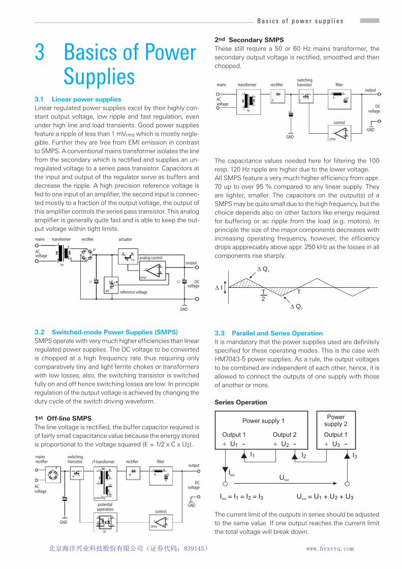
3.1 Linear power suppliesLinear regulated power supplies excel by their highly con-stant output voltage, low ripple and fast regulation, even under high line and load transients. Good power supplies feature a ripple of less than 1 mVrms which is mostly negle-gible. Further they are free from EMI emission in contrast to SMPS. A conventional mains transformer isolates the line from the secondary which is recti ed and supplies an un-regulated voltage to a series pass transistor. Capacitors at the input and output of the regulator serve as buffers and decrease the ripple. A high precision reference voltage is fed to one input of an ampli er, the second input is connec-ted mostly to a fraction of the output voltage, the output of this ampli er controls the series pass transistor. This analog ampli er is generally uite fast and is a le to keep the out-put voltage within tight limits.
3.2 Switched-mode Power Supplies (SMPS)SM S operate with very much higher ef ciencies than linear regulated power supplies. The DC voltage to be converted is chopped at a high frequency rate thus requiring only comparatively tiny and light ferrite chokes or transformers with low losses, also, the switching transistor is switched fully on and off hence switching losses are low. In principle regulation of the output voltage is achieved by changing the duty cycle of the switch driving waveform.
1st Off-line SMPSThe line voltage is recti ed, the uffer capacitor re uired is of fairly small capacitance value because the energy stored is proportional to the voltage squared (E = 1/2 x C x U2).
ACvoltage
mains transformer recti�er actuator
analog controloutput
reference voltageREF
DC voltage
GND
C1OPVA
C2
B1
TR1
ACvoltage
mainsrecti�er rf-transformer recti�er �lter
output
potential seperation
DCvoltage
GND
switchingtransistor
screening
OPVAOC
B
control
GND
2nd Secondary SMPSThese still require a 50 or 60 Hz mains transformer, the secondary output voltage is recti ed, smoothed and then chopped.
The capacitance values needed here for ltering the 100 resp. 120 Hz ripple are higher due to the lower voltage. All SM S feature a very much higher ef ciency from appr. 70 up to over 95 % compared to any linear supply. They are lighter, smaller. The capacitors on the output(s) of a SMPS may be quite small due to the high frequency, but the choice depends also on other factors like energy required for buffering or ac ripple from the load (e.g. motors). In principle the size of the major components decreases with increasing operating fre uency, however, the ef ciency drops apppreciably above appr. 250 kHz as the losses in all components rise sharply.
3.3 Parallel and Series OperationIt is mandatory that the power supplies used are de nitely speci ed for these operating modes. This is the case with HM7043-5 power supplies. As a rule, the output voltages to be combined are independent of each other, hence, it is allowed to connect the outputs of one supply with those of another or more.
Series Operation
The current limit of the outputs in series should be adjusted to the same value. If one output reaches the current limit the total voltage will break down.
ACvoltage
switchingtransistorrecti�er �lter
output
DCvoltage
GND
transformer
OPVA
control
TR
D T
GND
mains
TT
2
� Q2
� Q1
� I
B a s i c s o f p o w e r s u p p l i e s
北京海洋兴业科技股份有限公司(证券代码:839145) www.hyxyyq.com

Parallel Operation
In order to increase the total available current the outputs of supplies can be paralleled. The output voltages of the supplies involved are adjusted as accurately as possible to the same value. In this mode it is possible that one or more supplies enter the current limit mode. The output voltage remains in regulation as long as still at least one supply is in the voltage control mode. It is recommended but not a solutely necessary to ne ad ust the voltages such that the individual current contributions remain nearly equal. Of course, the maximum available output current is the sum of the individual supplies‘ maximum currents.
Example:A load requires 12 V at 2.7 A. Each 32 V output of the HM7042-5 can deliver 2 A. First set both supplies to 12 V. Then connect both black and both red safety connectors respectively in parallel. The load is connected to one of the supplies. With the pushbutton OUTPUT the voltage will be turned on. It is normal that one output will current limit at 2 A while the other will contribute the balance of 0.7 A in voltage regulation.
3.4 Current LimitCurrent limit means that a maximum current can be set. This is e.g. useful in order to protect a sensitive test circuit. In case of an inadvertent short in the test circuit the current will be limited to the value set which will in most cases prevent damage.
In case you should parallel power supplies of other manuf-acturers with HM7042-5 power supplies make sure all are specified for this mode of operation. If one supply of those connected in parallel should have insufficient overload protection it may be destroyed. HM7042-5 power supplies are specified for series and parallel operation.
The picture shows that the output voltage Vout remains stable, while the current I increases until the current limit selected will be reached. At this moment the instrument will change from constant voltage regulation to constant current regulation. Any further load increase will cause the current to remain stable while the voltage decreases ultimately to zero.
3.5 Electronic FuseIn order to provide a still better protection than current limiting offers the HM7042-5 features an electronic fuse. As soon as Imax is reached all outputs will be immediately simultaneously disabled. They may be turned on again by depressing OUPUT .
B a s i c s o f p o w e r s u p p l i e s
In this mode the output voltages add, the output current is the same for all supplies. As the sum of all voltages may well surpass the 42 V limit touching of live parts may be fatal! Only qualified and well instructed personnel is allowed to operate such installations.
I
out
U
out
U
const
I
max
I
out
U
out
U
const
I
max
Current limit
starts at 110% of I
max
short cut at
approx. 20% of I
max
Current limit
Adjustment of current
Ad
justm
en
to
fvo
lta
ge
C o n c e p t o f t h e H M 7 0 4 2 - 5
北京海洋兴业科技股份有限公司(证券代码:839145) www.hyxyyq.com

B a s i c s o f p o w e r s u p p l i e s
4 Concept of the HM7042-5
In this instrument the advantages of a SMPS, especially high ef ciency, and those of a linear regulator, e.g. high quality regulation, are combined. A high power DC/DC converter is used as a preregulator for the following linear regulators, this reduces the high losses typical of purely linear regulation. The HM 7042-5 has 3 independent and isolated voltage sources. In addition to the standard mode of operation as a triple output supply all outputs may be series or parallel connected.
In series conncetion the maximum available current is limited to 2 A. Paralleling the two 32 V outputs will yield 4 A at a maximum of 32 V. Please note that series as well as parallel conncetion may in uence some speci cations valid such as output impedance, noise, regulation.
4.1 Output power of the HM7042-5The maximum combined output power is 155.5 W. The HM7042-5 has a temperature-controlled fan the rpm of which will increase with rising temperature. This will ensure sufficient cooling under all normal operating conditions.
4.2 Switching the display on/offAll HM7042-5 power supplies feature a pushbutton which turns the outputs ON/OFF while the supply remains func-tioning. This allows to preset all voltages to their respective desired values prior to turning the outputs on by depressing OUTPUT .
Exceeding the Low Voltage Protection! For the series connection of all output voltages, it is pos-sible to exceed the low voltage protection of 42 V. Please note that in this case any contact with live components is life-threatening. It is assumed that only qualified and trained personnel service the power supplies and the connected loads.
5 Introduction to the operation
5.1 First time operationPlease observe especially the following notes:
– The line voltage indicated on the rear panel correspondsto the available line voltage, also, the correct fuses forthis line voltage are installed. The fuses are containedin the line voltage connector housing.
– The connection to the mains is either by plugging intoa socket with safety ground terminal or via an isolationtransformer of protection class II.
– No visible damage to the instrument.– No visible damage to the line cord.
No loose parts oating around in the instrument.
5.2 Turning on the HM7042-5After turning on all outputs will remain disabled, protecting the loads. Prior to pressing OUPUT all output voltages should be set to their desired values. Also, after turn-on the instrument will be in the operating mode “Current limit“. The maximum current available can be set by CURRENT . The mode “Electronic fuse“ may be selected after turn-on, but after each turn-off-on cycle “Current limit“ will be set.
C o n c e p t o f t h e H M 7 0 4 2 - 5
北京海洋兴业科技股份有限公司(证券代码:839145) www.hyxyyq.com

26
6 Operating controls and displays
6.1 Channel I + III0 – 32 V / 2 AOutput voltage, adjustable 0 – 32 V. Safety terminals for 4 mm plugs. The outputs are short circuit-proof with no time limit.
VOLT 4 digit displays (7 segment LEDs), of the actual values of all voltages, the resolution is 10 mV. The display are always operative, even when the outputs are disabled allowing pre-setting of all output voltages before the loads are connected to them. We recommend to follow always the procedure of setting the output voltages rst and then turn the outputs on.
LEDThese LEDs will light up if current limit is reached.
AMP4 digit displays (7 segment LEDs) of the actual output cur-rents, resolution 1 mA. We recommend to set the output current (Imax) before setting the output voltage and then turn on the outputs.
VOLTAGE/FINEotary controls for the coarse/ ne ad ustment of the 0 32
V outputs.
0 – 32 V / 2 AOutputs, 4 mm safety connectors
CURRENTRotary controls for setting the maximum currents of the 0 – 32 V outputs. If a control is turned CCW to 0 A all outputs
will be turned off immediately if the function “electronic fuse“ was activated. In case “Current limit“ was selected the LEDs will light up, the voltage will drop to zero.
0 – 5.5 V / 5 AThis output voltage can be adjusted 0 – 5.5 V. 4 mm sa-fety connectors. This output is short-circuit proof without a time limit.
6.2 Channel II VOLT
3 digit displays (7 segment LEDs) of the actual output voltage, resolution 10 mV. This display will show the output voltage even if the output was switched off. We recommend to follow always the procedure of setting the output voltage rst and then turn the output on.
LEDIf the current limit Imax is reached this LED will light up.
AMP. 3 digit displays (7 segment LEDs) of actual output currents, resolution 10 mA. We recommend to set the output current Imax prior to turning on the output voltages.
VOLTAGERotary control for setting the 0 – 5.5 V
0 – 5.5 V / 5 AOutput, 4 mm safety connectors.
CURRENT Rotary control for setting the maximum output current 0 – 5 A. If the control is turned CCW to 0 A all outpts will beturned off immediately if the mode “electronic fuse“ wasselected. In “current limit“ mode the LED will light up,the voltage will drop to zero.
O p e r a t i n g c o n t r o l s a n d d i s p l a y sO p e r a t i n g c o n t r o l s a n d d i s p l a y s
北京海洋兴业科技股份有限公司(证券代码:839145) www.hyxyyq.com

ELECTRONIC FUSE This pushbutton will activate the electronic fuse mode, indicated by LED [ON].
OUTPUTPushbutton for turning all 3 channels simultaneously ON/OFF, indicated by the LED [ON]. The voltage displays will remain unaffected.
6.3 Current LimitingAfter turn-on of the power supply it will always start in the CURRENT LIMIT mode. Using the CURRENT con-trols the maximum output current Imax can be set for each output separately. Onset of current limiting in one channel will not in uence the others. In order to ad ust Imax the appropriate output has to e short-circuited rst, then Imax can be set, the associated LED or will light up and indicate the current limit mode.
6.4 Electronic FusePrior to selection of this mode the current limits have to be set using the CURRENT controls. As outlined each output has to e short-circuited rst efore ad usting the appropriate CURRENT control. After setting Imax, the short has to be remov-ed. Then Electronic Fuse is depressed, the LED [ON] will light up indicating that the HM7042-5 is in the Electronic Fuse mode. In this mode all outputs will be immediately deactivated if the Imax of one channel is reached. In order to leave this mode press Electronic Fuse
again.
The current limits can be set using the controls CURRENT 0 – 2 A / 0 – 5 A. If a control is set CCW to 0 A indeed the
current will be zero, so the output capacitances will be dischar-ged slowly to 0 V. In “Current Limit“ mode the CCW position of a control will cause the associated LED to light up, the output voltage will decrease slowly. In the Electronic Fuse mode the CCW position of any CURRENT control will result in immedi-ate switching off of all channels after depressing OUPUT .
O p e r a t i n g c o n t r o l s a n d d i s p l a y sO p e r a t i n g c o n t r o l s a n d d i s p l a y s