hoffmann® ii surgical technique and brochure fixation frames allow for a wide range of elasticity...
TRANSCRIPT
Copy Goes Here™
Hoffmann® IISurgical Technique and Brochure

2
Gernot Asche, MDDepartment of TraumatologyRegional Hospital, Freudenstadt
Franz Burny, MS, PhDChairman, Department of OrthopaedicSurgeryCliniques Universitaires de BruxellesHôpital ErasmeUniversité Libre de Bruxelles
Charles M. Court-Brown, MD,FRCS(ORTH.)Consultant Orthopaedic SurgeonRoyal Infirmary of Edinburgh
Gabriele Falzarano, MDAzienda Ospedaliera “Rummo”Benevento
Erkki O. Karaharju, MD, MScDAssociate Professor of Orthopaedics andTraumatologyUniversity of Helsinki
Loren Latta, PE, PhDProfessor and Director of ResearchDepartment of Orthopaedics andRehabilitationUniversity of Miami School of Medicine
David Seligson, MDProfessor, Department of OrthopaedicSurgeryUniversity of LouisvilleHealth Science Center
Gregory Zych, DOAssociate ProfessorChief, Orthopaedic TraumaHealth Science CenterUniversity of Miami School of Medicine
8
3
4
2
1
6
5
3
IntroductionThe Hoffmann® II External Fixation Systemis a second generation modular external fixator offering advanced technology andease of application while maintaining thevalues of the original Hoffmann® ExternalFixation System.
Major improvements in materials and func-tion make the Hoffmann® II System pre-ferred over others. Clamp designs offer trueindependent pin placement with a patented“Snap-Fit” mechanism eliminating the needto pre-assemble components. Because of thesnap-fit design, components may be added to the frame at any time without having todismantle the frame and risk the loss ofreduction.
In addition to this patented feature,enhanced materials are used in the Clampsand Connecting rods. Clamps are made of aluminum alloy, significantly reducingweight without compromising stability.Connecting Rods are available in stainlesssteel, carbon fiber and aluminum allowingfor varying degrees of elasticity.
The Hoffmann® II System is fully compatiblewith the Monotube® Triax™, Hoffmann® IICompact™ and Hoffmann® II HybridExternal Fixation Systems.
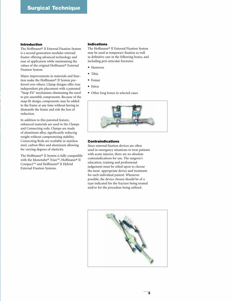
IndicationsThe Hoffmann® II External Fixation Systemmay be used as temporary fixation as well as definitive care in the following bones, andincluding peri-articular fractures:
• Humerus
• Tibia
• Femur
• Pelvis
• Other long bones in selected cases
ContraindicationsSince external fixation devices are often used in emergency situations to treat patientswith acute injuries, there are no absolutecontraindications for use. The surgeon's education, training and professional judgement must be relied upon to choose the most appropriate device and treatmentfor each individual patient. Whenever possible, the device chosen should be of atype indicated for the fracture being treatedand/or for the procedure being utilized.
Surgical Technique
4
Features & Benefits
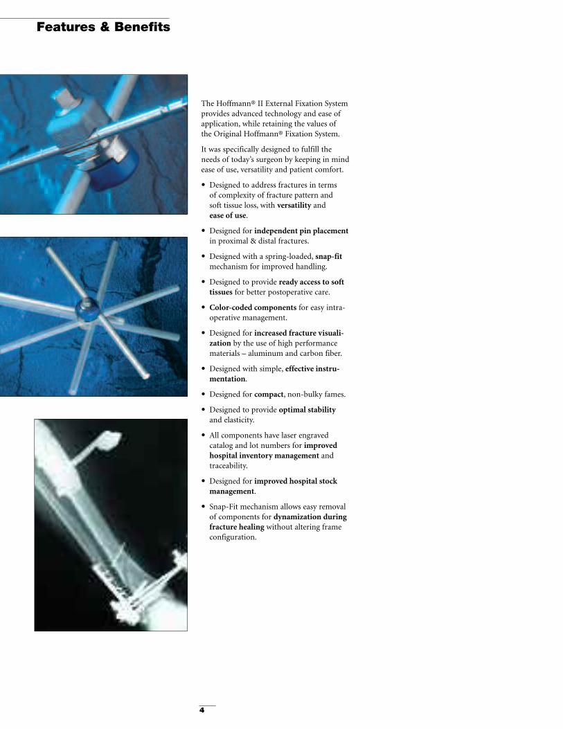
The Hoffmann® II External Fixation Systemprovides advanced technology and ease ofapplication, while retaining the values ofthe Original Hoffmann® Fixation System.
It was specifically designed to fulfill theneeds of today’s surgeon by keeping in mindease of use, versatility and patient comfort.
• Designed to address fractures in terms of complexity of fracture pattern and soft tissue loss, with versatility and ease of use.
• Designed for independent pin placementin proximal & distal fractures.
• Designed with a spring-loaded, snap-fitmechanism for improved handling.
• Designed to provide ready access to softtissues for better postoperative care.
• Color-coded components for easy intra-operative management.
• Designed for increased fracture visuali-zation by the use of high performancematerials – aluminum and carbon fiber.
• Designed with simple, effective instru-mentation.
• Designed for compact, non-bulky fames.
• Designed to provide optimal stabilityand elasticity.
• All components have laser engraved catalog and lot numbers for improvedhospital inventory management andtraceability.
• Designed for improved hospital stockmanagement.
• Snap-Fit mechanism allows easy removalof components for dynamization duringfracture healing without altering frameconfiguration.
5
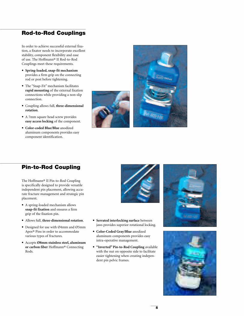
Rod-to-Rod Couplings
In order to achieve successful external fixa-tion, a fixator needs to incorporate excellentstability, component flexibility and ease of use. The Hoffmann® II Rod-to-RodCouplings meet these requirements.
• Spring-loaded, snap-fit mechanismprovides a firm grip on the connecting rod or post before tightening.
• The “Snap-Fit” mechanism facilitates rapid mounting of the external fixationconnections while providing a non-slipconnection.
• Coupling allows full, three-dimensionalrotation.
• A 7mm square head screw provides easy access locking of the component.
• Color-coded Blue/Blue anodized aluminum components provides easycomponent identification.
The Hoffmann® II Pin-to-Rod Coupling is specifically designed to provide versatileindependent pin placement, allowing accu-rate fracture management and strategic pinplacement.
• A spring-loaded mechanism allows snap-fit fixation and ensures a firm grip of the fixation pin.
• Allows full, three-dimensional rotation.
• Designed for use with Ø4mm and Ø5mmApex® Pins in order to accommodate various types of fractures.
• Accepts Ø8mm stainless steel, aluminumor carbon fiber Hoffmann® ConnectingRods.
• Serrated interlocking surface betweenjaws provides superior rotational locking.
• Color-Coded Gray/Blue anodized aluminum components provides easyintra-operative management.
• “Inverted” Pin-to-Rod Coupling availablewith the nut on opposite side to facilitateeasier tightening when creating indepen-dent pin pelvic frames.
Pin-to-Rod Coupling
6
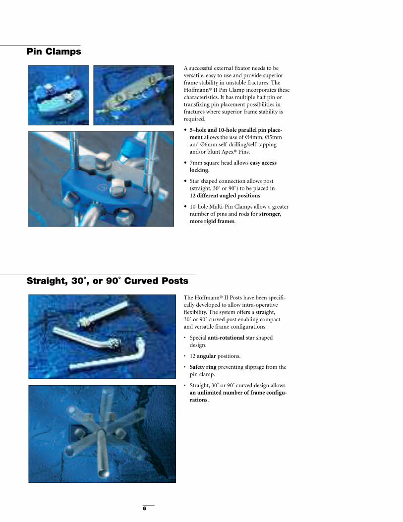
A successful external fixator needs to be versatile, easy to use and provide superiorframe stability in unstable fractures. TheHoffmann® II Pin Clamp incorporates thesecharacteristics. It has multiple half pin ortransfixing pin placement possibilities infractures where superior frame stability isrequired.
• 5–hole and 10-hole parallel pin place-ment allows the use of Ø4mm, Ø5mmand Ø6mm self-drilling/self-tappingand/or blunt Apex® Pins.
• 7mm square head allows easy access locking.
• Star shaped connection allows post(straight, 30˚ or 90˚) to be placed in 12 different angled positions.
• 10-hole Multi-Pin Clamps allow a greaternumber of pins and rods for stronger,more rigid frames.
The Hoffmann® II Posts have been specifi-cally developed to allow intra-operative flexibility. The system offers a straight,30˚ or 90˚ curved post enabling compactand versatile frame configurations.
• Special anti-rotational star shapeddesign.
• 12 angular positions.
• Safety ring preventing slippage from thepin clamp.
• Straight, 30˚ or 90˚ curved design allowsan unlimited number of frame configu-rations.
Pin Clamps
Straight, 30˚, or 90˚ Curved Posts

7
Dynamization/Distraction Rod
The Dynamization & Distraction Rod has an integrated variable elasticity mechanismallowing postoperative adjustment of the external fixation frame rigidity.
• Adjustable spring mechanism for variable elasticity, following the successful philosophy of the Monotube® Triax™ System.
• Degree of elastic incremental loading can be controlled by pre-setting the maximummovement of the device from 0 - 3mm.
• Compression/distraction device with a precise and easily adjustable 4.5cm integrallengthening device.
• Specifically designed Tube-to-Rod connections for secure fixation to the frame.
The compression of bone fragments in external fixation has remained a vital issue since an anatomical reduction is often the key to successful healing. With this in mind,the Hoffmann® II External Fixation System has developed a compression/distractiondevice that is versatile and easy to use.
• 4.5cm of compression and distraction.
• Visible calibration on the tube.
• 7mm square head screw that controls the compression/distraction.
• Specially designed Tube-to-Rod connections for secure fixation to the frame.
• Simple instrumentation.
• Laser engraved catalog and lot numbers for improved hospital inventory management and traceability.
Through the use of various materials such as aluminum or carbon fiber, the Hoffmann® II External Fixation System has complemented its range of existing stainless steel connecting rods, providing:
• Connecting rods in carbon fiber and anodized aluminum.
• Complete fracture visualization, thanks to the use of carbon fiber connecting rods,which permit x-ray visualization from angles otherwise obstructed by conventionalframes.
• Lightweight connecting rods (aluminum and carbon fiber) provide additional comfort for the patient and ease of assembly for the surgeon.
• Available in lengths from 65mm – 500mm.
Compression/Distraction Rod
Hoffmann® II Connecting Rods
8
Instruments
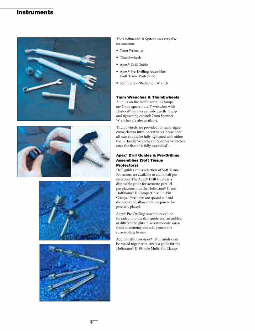
The Hoffmann® II System uses very fewinstruments:
• 7mm Wrenches
• Thumbwheels
• Apex® Drill Guide
• Apex® Pre-Drilling Assemblies (Soft Tissue Protectors)
• Stabilization/Reduction Wrench
7mm Wrenches & ThumbwheelsAll nuts on the Hoffmann® II Clamps are 7mm square nuts. T-wrenches withElastocil® handles provide excellent grip and tightening control: 7mm SpannerWrenches are also available.
Thumbwheels are provided for hand-tight-ening clamps intra-operatively (Please note:all nuts should be fully tightened with eitherthe T-Handle Wrenches or Spanner Wrenchesonce the fixator is fully assembled).
Apex® Drill Guides & Pre-DrillingAssemblies (Soft TissueProtectors)Drill guides and a selection of Soft TissueProtectors are available to aid in half pininsertion. The Apex® Drill Guide is a disposable guide for accurate parallel pin placement in the Hoffmann® II andHoffmann® II Compact™ Multi-Pin Clamps. Five holes are spaced at fixed distances and allow multiple pins to be precisely placed.
Apex® Pre-Drilling Assemblies can bethreaded into the drill guide and assembledat different heights to accommodate varia-tions in anatomy and still protect the surrounding tissues.
Additionally, two Apex® Drill Guides can be mated together to create a guide for theHoffmann® II 10-hole Multi-Pin Clamp.

9
Stabilization/Reduction WrenchesThe Stabilization/Reduction Wrenches can be used to stabilize the Pin-to-Rod and Rod-to-Rod Clamps during tightening. Using the open end of the Wrench, slide it over the clamp and hold it steady while tightening the clamp with the 7mm Wrench.
The Stabilization/Reduction Wrenches can also be used as reduction tools intra-operatively.Once the medial half of the frame is assembled, insert the wrench into the Post hole on thelateral side of the Multi-Pin Clamps, reduce the fracture, then tighten all medial components.Remove the wrenches and assemble the frame laterally. Be sure to tighten all components once the frame is fully assembled.
The Stabilization/Reduction Wrenches can also be assembled with the Multi-Pin Clamps tocreate a drill guide. Insert the wrench into the Post hole on the Multi-Pin Clamp to act as ahandle for the clamp. The newly created configuration is a perfect drill guide and can be usedwith the Pre-Drilling Assemblies to protect the surrounding tissues. Once the pins are insert-ed, the Pre-Drilling Assemblies and Stabilization/Reduction Wrench can be removed and theMulti-Pin clamp tightened to the pins.
Instruments
Assembling Stabilization/Reduction Wrench with Multi-PinClamp
Finished Drill Guide with Pre-Drilling Assemblies
10
Mechanical Characteristics
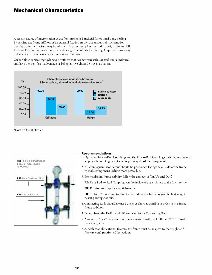
A certain degree of micromotion at the fracture site is beneficial for optimal bone healing.By varying the frame stiffness of an external fixation frame, the amount of micromotion distributed to the fracture may be adjusted. Because every fracture is different, Hoffmann® IIExternal Fixation frames allow for a wide range of elasticity by offering 3 types of connectingrod materials – stainless steel, aluminum and carbon.
Carbon fiber connecting rods have a stiffness that lies between stainless steel and aluminumand have the significant advantage of being lightweight and x-ray transparent.
0.00Stiffness Weight
20.00
40.00
60.00
80.00
100.00
Characteristic comparisons between ¿8mm carbon, aluminium and stainless steel rods
100.00
66.28
39.45
100.00
19.34
34.45
*Force given for 0.2 [mm]remanent deformation after
permanent relaxation
%
Stainless SteelCarbonAluminium
0.00HOFFMANN II
coupling tightened on
stainless steel rod
HOFFMANN IIcoupling tightened
on stainlesssteel rod
Competitor A coupling
tightened on stainless steel rod
HOFFMANN II coupling
tightened onaluminium rod
HOFFMANN IIcoupling tightened
on carbon rod
Competitor Acouplingtightened
on carbon rod
50.0
100.0
150.0
200.0
250.0
% Comparitive torsion measurements in Rod-to-Rod couplings
229.1
179.8
100.0
133.0
93.4
50.9
Recommendations1. Open the Rod-to-Rod Couplings and the Pin-to-Rod Couplings until the mechanical
stop is achieved to guarantee a proper snap-fit of the component.
2. All 7mm square head screws should be positioned facing the outside of the frame to make component locking more accessible.
3. For maximum frame stability, follow the analogy of “In, Up and Out”.
IN: Place Rod-to-Rod Couplings on the inside of posts, closest to the fracture site.
UP: Position nuts up for easy tightening.
OUT: Place Connecting Rods on the outside of the frame to give the best weight bearing configurations.
4. Connecting Rods should always be kept as short as possible in order to maximize frame stability.
5. Do not bend the Hoffmann® Ø8mm Aluminum Connecting Rods.
6. Always use Apex® Fixation Pins in combination with the Hoffmann® II ExternalFixation System.
7. As with modular external fixators, the frame must be adapted to the weight and fracture configuration of the patient.
IN: Rod-to-Rod Clamps on Inside of Post, Closest to Fracture.
UP: Nuts Positioned Up
OUT: Rods Face Out
*
*Data on file at Stryker

11
Humeral Frame - Unilateral1. 4mm Apex® Half Pins are placed in the humeral diaphysis using classical parallel pin
placement of two Pin Clamp Assemblies (The Multi-Pin Clamp Assemblies should be used as a guide for pin insertion to guarantee parallel pin placement).
2. The Proximal Pins should be placed in the lateral and/or posterior aspects of the humerus.
3. Two 30˚Angled Posts are inserted into the Multi-Pin Clamps in an inverted “V” position.
4. Connect the two Pin Clamp Assemblies together using two Rod-to-Rod Clamps and an8mm Connecting Rod of the proper length.
5. Since precise reduction is not required prior to pin insertion, the frame may be assembledand the final reduction made with the frame in situ.
6. If a bony fragment must be stabilized, capture the fragment with an additional 4mm Apex®Half Pin and connect to the 8mm Connecting Rod with a Pin-to-Rod Clamp.
Humerus
Surgical Technique
Humeral Frame – Independent PinThe frame provides minimal external fixation for stabilization of the humerus.
1. Independent pin placement of two proximal Apex® Half Pins in the lateral and/or posterioraspect of the distal humerus is performed.
2. Connect all Single Pins to two 8mm Connecting Rods using Pin-to-Rod Clamps.
CAT # DESCRIPTION QTY4920-1-020 Hoffmann® II Pin-to-Rod Clamp 4
Ø8mm Connecting Rods 2Apex® Pins 4
CAT # DESCRIPTION QTY4920-1-010 Hoffmann® II Rod-to-Rod Clamp 24920-2-020 Hoffmann® II Multi-Pin Clamp 24920-2-140 Hoffmann® II 30˚ Post 2
Ø8mm Connecting Rods 1Apex® Pins 4

12
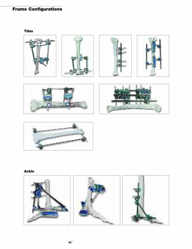
Tibia
Proximal Tibia Circular Frame1. Place three Ø5mm Apex® Half Pins
independently in the proximal tibia using the Curved Rod as a guide.
2. Connect all pins to the Curved Rod using Pin-to-Rod Clamps.
3. Place two Ø5mm Apex® Half Pins in thetibial diaphysis using classical parallel pinplacement with the Multi-Pin ClampAssembly (The Multi-Pin Clamp shouldbe used as a guide for parallel placementof the pins).
4. Two 30˚ Angled Posts are inserted into the Multi-Pin Clamps in an inverted “V”position.
5. Connect the Multi-Pin Clamp assembly to the Curved Rod with two 8mmConnecting Rods and four Rod-to RodClamps.
Standard Mid-Shaft Tibia Frame
1. 5mm Apex® Half Pins are placed in thetibia using classical parallel pin placement(The Multi-Pin Clamp should be used as a guide for parallel placement of the pin).
2. Four 30˚ Angled Posts are inserted into the Multi Pin Clamp in an inverted “V”position.
3. Connect the two Pin Clamp Assembliesusing four Rod-to-Rod Clamps and two Ø8 mm Connecting Rods of the appropri-ate length and material.
4. Since precise reduction is not requiredprior to pin insertion, the frame can beassembled and the final reduction can beperformed with the frame in situ before all components are locked in place.
5. If greater stability is required or a bonyfragment must be stabilized, use two additional Rod-to-Rod Clamps and an8mm Connecting Rod to join the medialand lateral Connecting Rods.
6. Capture the bony fragment with a 5mm Apex® Half Pin and attach to thetransverse 8mm Connecting Rod with a Pin-to-Rod Clamp.
CAT # DESCRIPTION QTY5029-7-030 Hoffmann® II Curved Aluminum Rod 14920-1-020 Hoffmann® II Pin-to-Rod Clamp 34920-1-010 Hoffmann® II Rod-to-Rod Clamp 44920-2-020 Hoffmann® II Multi-Pin Clamp 14920-2-140 Hoffmann® II 30˚ Post 2
Ø8mm Connecting Rods 2Apex® Pins 5
CAT # DESCRIPTION QTY4920-1-010 Hoffmann® II Rod-to-Rod Clamp 44920-2-020 Hoffmann® II Multi-Pin Clamp 24920-2-140 Hoffmann® II 30˚ Post 4
Ø8mm Connecting Rods 2Apex® Pins 4

13
Tibia
Distal Tibia Circular Frame
1. Place three 5mm Apex® Half Pins independently in the distal tibia using the Curved Rod as a guide.
2. Connect all Single Pins to the Curved Rod using Pin-to-Rod Clamps.
3. 5mm Apex® Half Pins are placed in thetibia using classical parallel pin placement(The Multi-Pin Clamp should be used as a guide for parallel placement of the pins).
4. Two 30˚ Angled Posts are inserted into the Multi-Pin Clamp in an inverted “V”position.
5. Connect the Multi-Pin Clamp Assembly tothe Curved Aluminum Rod with two 8mmConnecting Rods and four Rod-to-RodClamps.
Distal Tibia Independent PinFrame
This frame is for extra-articular and distaltibial fractures close to the joint. It may be supplemented with internal fixation.
1. 5mm Apex® Half Pins are placed in thetibial diaphysis using classical parallel pinplacement (The Multi-Pin Clamp shouldbe used as a guide for parallel pin place-ments).
2. Two 30˚ Angled Posts are inserted into the Multi-Pin Clamp in an inverted “V”position.
3. Independent pin placement is in theantero-medial and lateral planes of thetibia using 5mm Apex® Half Pins.
4. Connect the Proximal Pin Clamp assemblyto the Distal Pins using Pin-to-Rod andRod-to-Rod Clamps and the appropriatelength Connecting Rods.
CAT # DESCRIPTION QTY5029-7-030 Hoffmann® II Curved 1
Aluminum Rod4920-1-020 Hoffmann® II Pin-to-Rod Clamp 34920-1-010 Hoffmann® II Rod-to-Rod Clamp 44920-2-020 Hoffmann® II Multi-Pin Clamp 14920-2-140 Hoffmann® II 30˚ Post 2
Ø8mm Connecting Rods 2Apex® Pins 5
CAT # DESCRIPTION QTY4920-1-020 Hoffmann® II Pin-to-Rod Clamp 24920-1-010 Hoffmann® II Rod-to-Rod Clamp 24920-2-020 Hoffmann® II Multi-Pin Clamp 14920-2-140 Hoffmann® II 30˚ Post 2
Ø8mm Connecting Rods 2Apex® Pins 4

14
Ankle
Ankle Stabilization Frame
1. Place 5mm Apex® Half Pins independentlyin the tibial diaphysis and the calcaneus.
2. Place a 4mm Apex® Half Pin independentlyin the first metatarsal.
3. Connect all Single Pins to 8mm ConnectingRods of the appropriate length.
4. Connect the 8mm Rods with a Rod-to-RodClamp.
Ankle Bridging Frame
1. Place two parallel 4mm Apex® TransfixingPins in the calcaneus.
2. A Multi-Pin Clamp assembly should beused as a pin insertion guide to guaranteeparallel transfixing pin placement.
3. Two Multi-Pin Clamp assemblies with one 30˚ Angled Post are placed on eachside of the ankle.
4. Place two parallel 5mm Apex® Half Pinson the anterior medial aspect of the tibialcrest with a Multi-Pin Clamp and two 30˚Angled Posts.
5. Connect the Pin Clamp assemblies usingfour Rod-to-Rod Clamps and two 8mmConnecting Rods of the appropriatelength.
Ankle Stabilization Frame
1. Place 5mm Apex® Half Pins independentlyin the tibial diaphysis and the calcaneus.
2. Place a 4mm Apex® Half Pin independentlyin the first metatarsal.
3. Connect all Single Pins to 8mm ConnectingRods of the appropriate length.
4. Connect the 8mm Rods with a Rod-to-RodClamp.
CAT # DESCRIPTION QTY4920-1-020 Hoffmann® II Pin-to-Rod Clamp 44920-1-010 Hoffmann® II Rod-to-Rod Clamp 3
Ø8mm Connecting Rods 35mm Apex® Pins 34mm Apex® Pins 1
CAT # DESCRIPTION QTY4920-1-020 Hoffmann® II Pin-to-Rod Clamp 34920-1-010 Hoffmann® II Rod-to-Rod Clamp 1
Ø8mm Connecting Rods 2Apex® Pins 3
CAT # DESCRIPTION QTY4920-1-010 Hoffmann® II Rod-to-Rod Clamp 44920-2-020 Hoffmann® II Multi-Pin Clamp 34920-2-140 Hoffmann® II 30˚ Post 24920-2-120 Hoffmann® II Straight Post 2
Ø8mm Connecting Rods 2Apex® Pins 4
15
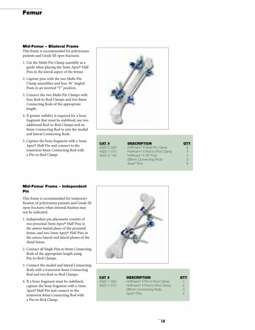
Mid-Femur Frame – IndependentPin
This frame is recommended for temporaryfixation of polytrauma patients and Grade IIIopen fractures when internal fixation maynot be indicated.
1. Independent pin placement consists oftwo proximal 5mm Apex® Half Pins in the antero-lateral plane of the proximalfemur, and two 5mm Apex® Half Pins inthe antero-lateral and lateral planes of thedistal femur.
2. Connect all Single Pins to 8mm ConnectingRods of the appropriate length using Pin-to-Rod Clamps.
3. Connect the medial and lateral ConnectingRods with a transverse 8mm ConnectingRod and two Rod-to-Rod Clamps.
4. If a bony fragment must be stabilized,capture the bony fragment with a 5mmApex® Half Pin and connect to the transverse 8mm Connecting Rod with a Pin-to-Rod Clamp.
Femur
CAT # DESCRIPTION QTY4920-2-020 Hoffmann® II Multi-Pin Clamp 24920-1-010 Hoffmann® II Rod-to-Rod Clamp 44920-2-140 Hoffmann® II 30˚ Post 4
Ø8mm Connecting Rods 2Apex® Pins 8
CAT # DESCRIPTION QTY4920-1-020 Hoffmann® II Pin-to-Rod Clamp 44920-1-010 Hoffmann® II Rod-to-Rod Clamp 2
Ø8mm Connecting Rods 3Apex® Pins 4
Mid-Femur – Bilateral Frame This frame is recommended for polytraumapatients and Grade III open fractures.
1. Use the Multi-Pin Clamp assembly as aguide when placing the 5mm Apex® HalfPins in the lateral aspect of the femur.
2. Capture pins with the two Multi-PinClamp assemblies and four 30˚ AngledPosts in an inverted “V” position.
3. Connect the two Multi-Pin Clamps withfour Rod-to-Rod Clamps and two 8mmConnecting Rods of the appropriatelength.
4. If greater stability is required for a bonyfragment that must be stabilized, use twoadditional Rod-to-Rod Clamps and an8mm Connecting Rod to join the medialand lateral Connecting Rods.
5. Capture the bony fragment with a 5mmApex® Half Pin and connect to thetransverse 8mm Connecting Rod with a Pin-to-Rod Clamp.
16
Frame Configurations
Ankle
Tibia

17
Humerus
Pelvis
Femur
18
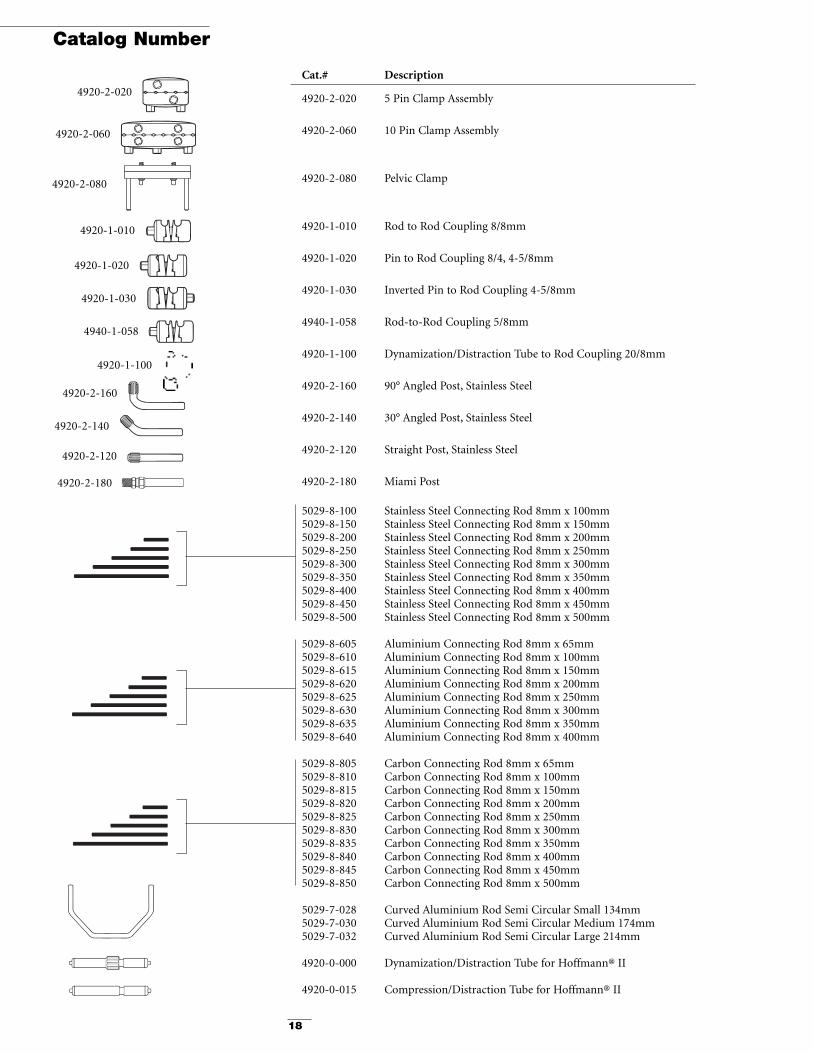
Catalog Number
Cat.# Description
4920-2-020 5 Pin Clamp Assembly
4920-2-060 10 Pin Clamp Assembly
4920-2-080 Pelvic Clamp
4920-1-010 Rod to Rod Coupling 8/8mm
4920-1-020 Pin to Rod Coupling 8/4, 4-5/8mm
4920-1-030 Inverted Pin to Rod Coupling 4-5/8mm
4940-1-058 Rod-to-Rod Coupling 5/8mm
4920-1-100 Dynamization/Distraction Tube to Rod Coupling 20/8mm
4920-2-160 90° Angled Post, Stainless Steel
4920-2-140 30° Angled Post, Stainless Steel
4920-2-120 Straight Post, Stainless Steel
4920-2-180 Miami Post
5029-8-100 Stainless Steel Connecting Rod 8mm x 100mm5029-8-150 Stainless Steel Connecting Rod 8mm x 150mm5029-8-200 Stainless Steel Connecting Rod 8mm x 200mm5029-8-250 Stainless Steel Connecting Rod 8mm x 250mm5029-8-300 Stainless Steel Connecting Rod 8mm x 300mm5029-8-350 Stainless Steel Connecting Rod 8mm x 350mm5029-8-400 Stainless Steel Connecting Rod 8mm x 400mm5029-8-450 Stainless Steel Connecting Rod 8mm x 450mm5029-8-500 Stainless Steel Connecting Rod 8mm x 500mm
5029-8-605 Aluminium Connecting Rod 8mm x 65mm5029-8-610 Aluminium Connecting Rod 8mm x 100mm5029-8-615 Aluminium Connecting Rod 8mm x 150mm5029-8-620 Aluminium Connecting Rod 8mm x 200mm5029-8-625 Aluminium Connecting Rod 8mm x 250mm5029-8-630 Aluminium Connecting Rod 8mm x 300mm5029-8-635 Aluminium Connecting Rod 8mm x 350mm5029-8-640 Aluminium Connecting Rod 8mm x 400mm
5029-8-805 Carbon Connecting Rod 8mm x 65mm5029-8-810 Carbon Connecting Rod 8mm x 100mm5029-8-815 Carbon Connecting Rod 8mm x 150mm5029-8-820 Carbon Connecting Rod 8mm x 200mm5029-8-825 Carbon Connecting Rod 8mm x 250mm5029-8-830 Carbon Connecting Rod 8mm x 300mm5029-8-835 Carbon Connecting Rod 8mm x 350mm5029-8-840 Carbon Connecting Rod 8mm x 400mm5029-8-845 Carbon Connecting Rod 8mm x 450mm5029-8-850 Carbon Connecting Rod 8mm x 500mm
5029-7-028 Curved Aluminium Rod Semi Circular Small 134mm5029-7-030 Curved Aluminium Rod Semi Circular Medium 174mm5029-7-032 Curved Aluminium Rod Semi Circular Large 214mm
4920-0-000 Dynamization/Distraction Tube for Hoffmann® II
4920-0-015 Compression/Distraction Tube for Hoffmann® II
4920-2-020
4920-2-060
4920-2-080
4920-1-010
4920-1-020
4920-1-030
4940-1-058
4920-1-100
4920-2-160
4920-2-140
4920-2-120
4920-2-180
19
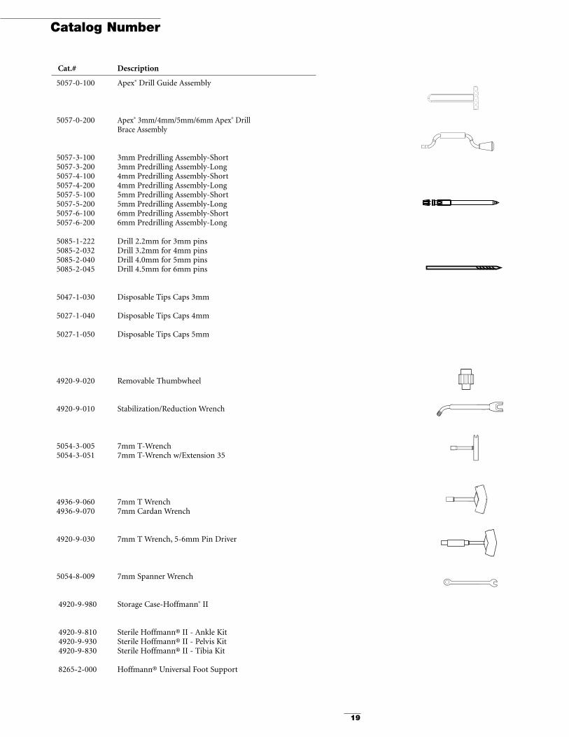
Catalog Number
Cat.# Description
5057-0-100 Apex® Drill Guide Assembly
5057-0-200 Apex® 3mm/4mm/5mm/6mm Apex® DrillBrace Assembly
5057-3-100 3mm Predrilling Assembly-Short5057-3-200 3mm Predrilling Assembly-Long5057-4-100 4mm Predrilling Assembly-Short5057-4-200 4mm Predrilling Assembly-Long5057-5-100 5mm Predrilling Assembly-Short5057-5-200 5mm Predrilling Assembly-Long5057-6-100 6mm Predrilling Assembly-Short5057-6-200 6mm Predrilling Assembly-Long
5085-1-222 Drill 2.2mm for 3mm pins5085-2-032 Drill 3.2mm for 4mm pins5085-2-040 Drill 4.0mm for 5mm pins5085-2-045 Drill 4.5mm for 6mm pins
5047-1-030 Disposable Tips Caps 3mm
5027-1-040 Disposable Tips Caps 4mm
5027-1-050 Disposable Tips Caps 5mm
4920-9-020 Removable Thumbwheel
4920-9-010 Stabilization/Reduction Wrench
5054-3-005 7mm T-Wrench5054-3-051 7mm T-Wrench w/Extension 35
4936-9-060 7mm T Wrench4936-9-070 7mm Cardan Wrench
4920-9-030 7mm T Wrench, 5-6mm Pin Driver
5054-8-009 7mm Spanner Wrench
4920-9-980 Storage Case-Hoffmann® II
4920-9-810 Sterile Hoffmann® II - Ankle Kit4920-9-930 Sterile Hoffmann® II - Pelvis Kit4920-9-830 Sterile Hoffmann® II - Tibia Kit
8265-2-000 Hoffmann® Universal Foot Support
The information presented in this brochure is intended to demonstrate the breadth of Stryker product offerings. Alwaysrefer to the package insert, product label and/or user instructions before using any Stryker product. Surgeons must alwaysrely on their own clinical judgment when deciding which treatments and procedures to use with patients. Products may notbe available in all markets. Product availability is subject to the regulatory or medical practices that govern individual mar-kets. Please contact your Stryker representative if you have questions about the availability of Stryker products in your area.
The marks bearing the symbol TM are trademarks of Stryker.The marks bearing the symbol ® are registered trademarks of Stryker.
Literature Number: LH2TG Rev. 1GC/GS 3m 07/05
Copyright ©2005 StrykerPrinted in USA
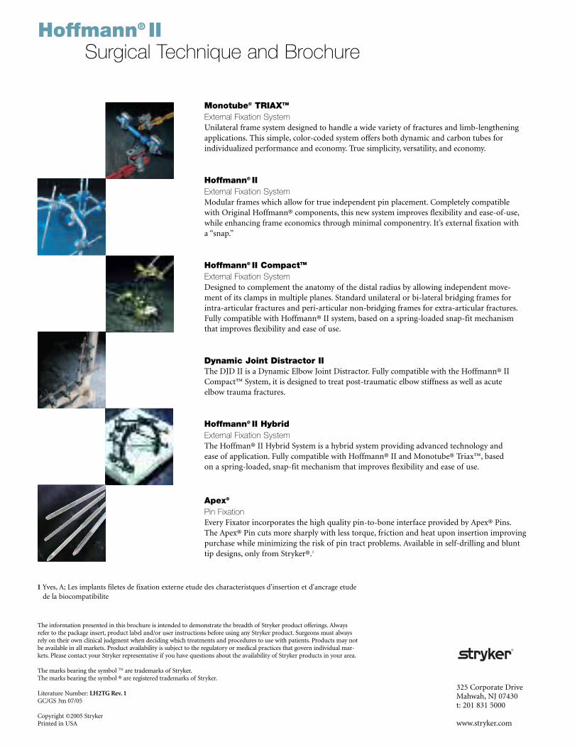
Hoffmann® IISurgical Technique and Brochure
Monotube® TRIAXTM
External Fixation SystemUnilateral frame system designed to handle a wide variety of fractures and limb-lengtheningapplications. This simple, color-coded system offers both dynamic and carbon tubes for individualized performance and economy. True simplicity, versatility, and economy.
Hoffmann® IIExternal Fixation SystemModular frames which allow for true independent pin placement. Completely compatiblewith Original Hoffmann® components, this new system improves flexibility and ease-of-use,while enhancing frame economics through minimal componentry. It’s external fixation with a “snap.”
Hoffmann® II CompactTM
External Fixation SystemDesigned to complement the anatomy of the distal radius by allowing independent move-ment of its clamps in multiple planes. Standard unilateral or bi-lateral bridging frames for intra-articular fractures and peri-articular non-bridging frames for extra-articular fractures.Fully compatible with Hoffmann® II system, based on a spring-loaded snap-fit mechanismthat improves flexibility and ease of use.
Dynamic Joint Distractor IIThe DJD II is a Dynamic Elbow Joint Distractor. Fully compatible with the Hoffmann® IICompact™ System, it is designed to treat post-traumatic elbow stiffness as well as acute elbow trauma fractures.
Hoffmann® II HybridExternal Fixation SystemThe Hoffman® II Hybrid System is a hybrid system providing advanced technology and ease of application. Fully compatible with Hoffmann® II and Monotube® Triax™, based on a spring-loaded, snap-fit mechanism that improves flexibility and ease of use.
Apex®
Pin FixationEvery Fixator incorporates the high quality pin-to-bone interface provided by Apex® Pins.The Apex® Pin cuts more sharply with less torque, friction and heat upon insertion improvingpurchase while minimizing the risk of pin tract problems. Available in self-drilling and blunttip designs, only from Stryker®.1
325 Corporate DriveMahwah, NJ 07430t: 201 831 5000
www.stryker.com
1 Yves, A; Les implants filetes de fixation externe etude des characteristques d'insertion et d'ancrage etudede la biocompatibilite