holding electromagnets holding electromagnets · 103 rectangular holding electromagnets the...
TRANSCRIPT
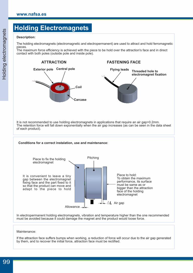
Description:
The holding electromagnets (electromagnetic and electropermanent) are used to attract and hold ferromagneticpieces.The maximum force efficiency is achieved with the piece to be hold over the attraction's face and in directcontact with both poles (outside pole and inside pole).
Conditions for a correct instalation, use and maintenance:
Holding Electromagnets
ATTRACTION FASTENING FACE
Central pole Flying leads
Carcase
Exterior pole
In electropermanent holding electromagnets, vibration and temperature higher than the one recommendedmust be avoided because it could damage the magnet and the product would loose force.
Maintenance:
If the attraction face suffers bumps when working, a reduction of force will occur due to the air gap generatedby them, and to recover the initial force, attraction face must be rectified.
Coil
It is convenient to leave a tinygap between the electromagnetfixing face and the part fixed to itso that the product can move andadapt to the piece to hold
Air gap
Pitching
Piece to hold:To obtain the maximumperformance, its surfacemust be same as orbigger than the attractionface of the holdingelectromagnet
AllowancedL
Piece to fix the holdingelectromagnet
Threaded hole toelectromagnet fixation
It is not recommended to use holding electromagnets in applications that require an air gap>0.2mm.The retention force will fall down exponentially when the air gap increases (as can be seen in the data sheetof each product).
99
www.nafsa.es
Hol
ding
ele
ctro
mag
nets
The models described in the catalogue are standard and minimum manufacturing batches are not required.However, there is the possibility of customizing them to suit better customer's needs. See below some of themost common customizations.If any modification is needed, please ask NAFSA about the possibility and the minimum manufacturing batchrequired.
CUSTOMIZATION: Holding electromagnets
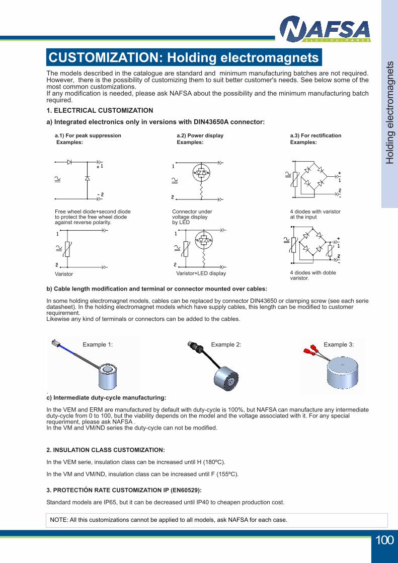
1. ELECTRICAL CUSTOMIZATION
b) Cable length modification and terminal or connector mounted over cables:
In some holding electromagnet models, cables can be replaced by connector DIN43650 or clamping screw (see each seriedatasheet). In the holding electromagnet models which have supply cables, this length can be modified to customerrequirement.Likewise any kind of terminals or connectors can be added to the cables.
3. PROTECTIÓN RATE CUSTOMIZATION IP (EN60529):
Standard models are IP65, but it can be decreased until IP40 to cheapen production cost.
.c) Intermediate duty-cycle manufacturing:
In the VEM and ERM are manufactured by default with duty-cycle is 100%, but NAFSA can manufacture any intermediateduty-cycle from 0 to 100, but the viability depends on the model and the voltage associated with it. For any specialrequeriment, please ask NAFSA .In the VM and VM/ND series the duty-cycle can not be modified.
2. INSULATION CLASS CUSTOMIZATION:
In the VEM serie, insulation class can be increased until H (180ºC).
In the VM and VM/ND, insulation class can be increased until F (155ºC).
NOTE: All this customizations cannot be applied to all models, ask NAFSA for each case.
a) Integrated electronics only in versions with DIN43650A connector:
a.1) For peak suppression Examples:
a.2) Power displayExamples:
Free wheel diode+second diodeto protect the free wheel diodeagainst reverse polarity.
Varistor
Connector undervoltage displayby LED
Varistor+LED display
4 diodes with varistorat the input
4 diodes with doblevaristor.
a.3) For rectificationExamples:
Example 1: Example 2: Example 3:
100
Hol
ding
ele
ctro
mag
nets
The models described in the catalogue are standard and minimum manufacturing batches are not required.However, there is the possibility of customizing them to suit better customer's needs. See below some of themost common customizations.If any modification is needed, please ask NAFSA about the possibility and the minimum manufacturing batchrequired.
CUSTOMIZATION: Holding electromagnets
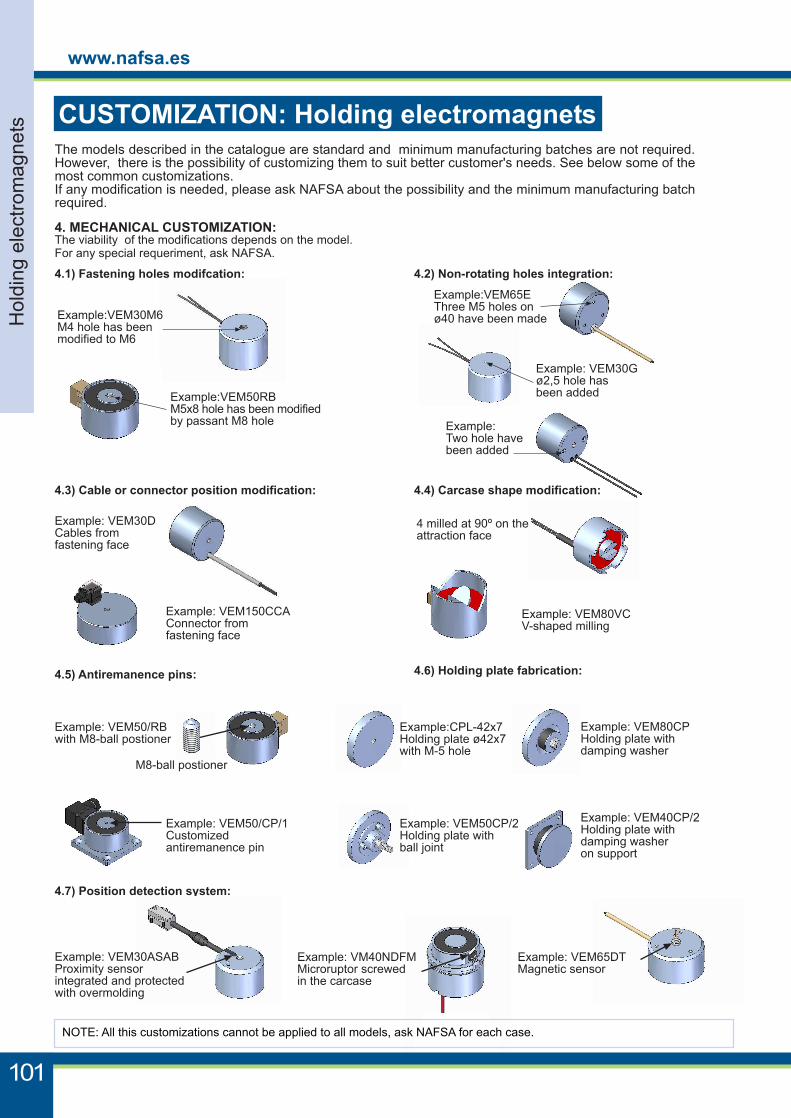
4. MECHANICAL CUSTOMIZATION:The viability of the modifications depends on the model.For any special requeriment, ask NAFSA.
NOTE: All this customizations cannot be applied to all models, ask NAFSA for each case.
4.1) Fastening holes modifcation:
4.6) Holding plate fabrication:
4.7) Position detection system:
4.2) Non-rotating holes integration:
4.3) Cable or connector position modification:
Example:VEM50RBM5x8 hole has been modifiedby passant M8 hole
Example:VEM65EThree M5 holes onø40 have been made
Example: VEM30Gø2,5 hole hasbeen added
Example: VEM30DCables fromfastening face
4 milled at 90º on theattraction face
Example: VEM80VCV-shaped milling
Example: VEM30ASABProximity sensorintegrated and protectedwith overmolding
Example: VM40NDFMMicroruptor screwedin the carcase
Example: VEM65DTMagnetic sensor
Example:VEM30M6M4 hole has beenmodified to M6
Example:CPL-42x7Holding plate ø42x7with M-5 hole
Example: VEM80CPHolding plate withdamping washer
Example: VEM50CP/2Holding plate withball joint
Example: VEM150CCAConnector fromfastening face
Example:Two hole havebeen added
4.4) Carcase shape modification:
Example: VEM40CP/2Holding plate withdamping washeron support
4.5) Antiremanence pins:
Example: VEM50/RBwith M8-ball postioner
M8-ball postioner
Example: VEM50/CP/1Customizedantiremanence pin
www.nafsa.es
Hol
ding
ele
ctro
mag
nets
101
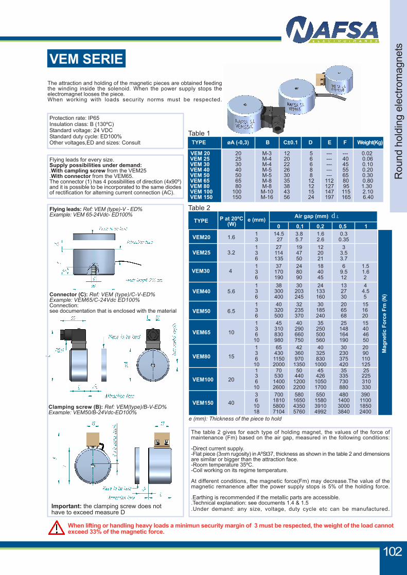
Important: the clamping screw does nothave to exceed measure D
VEM SERIEThe attraction and holding of the magnetic pieces are obtained feedingthe winding inside the solenoid. When the power supply stops theelectromagnet looses the piece.When working with loads security norms must be respected.
Protection rate: IP65Insulation class: B (130ºC)Standard voltage: 24 VDCStandard duty cycle: ED100%Other voltages,ED and sizes: Consult
Flying leads for every size.Supply possibilities under demand:.With campling screw from the VEM25.With connector from the VEM65.The connector (1) has 4 possibilities of direction (4x90º)and it is possible to be incorporated to the same diodesof rectification for alterning current connection (AC).
The table 2 gives for each type of holding magnet, the values of the force ofmaintenance (Fm) based on the air gap, measured in the following conditions:
-Direct current supply.-Flat piece (3mm rugosity) in AºSt37, thickness as shown in the table 2 and dimensionsare similar or bigger than the attraction face.-Room temperature 35ºC.-Coil working on its regime temperature.
At different conditions, the magnetic force(Fm) may decrease.The value of themagnetic remanence after the power supply stops is 5% of the holding force.
.Earthing is recommended if the metallic parts are accessible.
.Technical explanation: see documents 1.4 & 1.5
.Under demand: any size, voltage, duty cycle etc can be manufactured.
When lifting or handling heavy loads a minimun security margin of 3 must be respected, the weight of the load cannotexceed 33% of the magnetic force.
Flying leads: Ref: VEM (type)-V - ED%Example: VEM 65-24Vdc- ED100%
Connector (C): Ref: VEM (type)/C-V-ED%Example: VEM65/C-24Vdc ED100%Connection:see documentation that is enclosed with the material
Clamping screw (B): Ref: VEM(type)/B-V-ED%Example: VEM50/B-24Vdc-ED100%
Rou
nd h
oldi
ng e
lect
rom
agne
ts
102
Table 1 TYPE øA (-0,3) B C±0.1 D E F Weight(Kg)
VEM 20 20 M-3 12 5 --- --- 0.02 VEM 25 25 M-4 20 6 --- 40 0.06 VEM 30 30 M-4 22 6 --- 45 0.10 VEM 40 40 M-5 26 8 --- 55 0.20 VEM 50 50 M-5 30 8 --- 65 0.30 VEM 65 65 M-8 35 12 112 80 0.80 VEM 80 80 M-8 38 12 127 95 1.30 VEM 100 100 M-10 43 15 147 115 2.10 VEM 150 150 M-16 56 24 197 165 6.40
Mag
netic
For
ce F
m (N
)
VEM20 1.6
TYPE P at 20ºC (W)
e (mm)Air gap (mm) dL
0 0,1 0,2 0,5 1
VEM25 3.2
VEM30 4
VEM40 5.6
VEM50 6.5
VEM65 10
VEM80 15
VEM100 20
VEM150 40
e (mm): Thickness of the piece to hold
Table 2
3 700 580 550 480 390 6 1810 1650 1580 1400 1100
10 5800 4350 3910 3000 185018 7104 5760 4992 3840 2400
1 70 50 45 35 253 530 440 426 335 2256 1400 1200 1050 730 310
10 2600 2200 1700 880 330
1 65 42 40 30 203 430 360 325 230 906 1150 970 830 375 110
10 2000 1350 1000 420 125
1 45 40 35 25 153 310 290 250 148 406 830 660 500 164 46
10 980 750 560 190 50
1 40 32 30 20 153 320 235 185 65 166 500 370 240 68 20
1 38 30 24 13 43 300 203 133 27 4.56 400 245 160 30 5
1 37 24 18 6 1.53 170 80 40 9.5 1.66 190 90 45 12 2
1 27 19 12 33 114 47 20 3.56 135 50 21 3.7
1 14.5 3.8 1.6 0.33 27 5.7 2.6 0.35
103
www.nafsa.es
Rec
tang
ular
hol
ding
ele
ctro
mag
nets
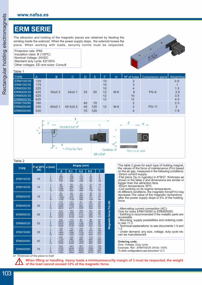
The attraction and holding of the magnetic pieces are obtained by feeding thewinding inside the solenoid. When the power supply stops, the solenoid looses thepiece. When working with loads, security norms must be respected.
When lifting or handling heavy loads a minimumsecurity margin of 3 must be respected, the weightof the load cannot exceed 33% of the magnetic force.
3
Protection rate: IP65Insulation class: B (130ºC)Nominal Voltage: 24VDCStandard duty cycle: ED100%Other voltages, ED and sizes: Consult
- Alternating current connection (AC):Only for sizes ERM150/60 to ERM500/60.- Earthing is recommended if the metallic parts areaccessible.- Mounting, supply possibilities and ordering code:to see 11.3- Technical explanations: to see documents 1.4 and1.5- Under demand: any size, voltage, duty cycle etccan be manufactured
The table 2 gives for each type of holding magnet,the values of the force of maintenance (Fm) basedon the air gap, measured in the following conditions:-Direct current supply.-Flat piece (3µ m rugosity) in AºSt37, thickness asshown in the table 2 and dimensions are similar orbigger than the attraction face.-Room temperature 35ºC.-Coil working on its regime temperature.At different conditions, the magnetic force(Fm) maydecrease.The value of the magnetic remanenceafter the power supply stops is 5% of the holdingforce.
ERM SERIE
Ordering code:Size; Voltage; Duty cycleExample: Ref.: ERM150/35 24Vdc 100%To other configurations see document 12.3
P at 20ºC (W)
ERM100/35 10
ERM150/35 14
ERM200/35 18
ERM400/35 30
ERM500/35 45
ERM600/35 53
ERM150/60 25
ERM200/60 40
ERM500/60 75
Mag
netic
forc
e Fm
(N)
TYPE e (mm) Airgap (mm)
1 32 22 12 8 6 3 396 308 120 45 8 6 604 320 190 52 1210 752 468 238 60 18 1 65 50 30 21 14 3 769 580 220 82 17 6 1090 657 368 90 2110 1450 904 490 116 35 1 80 60 42 28 14 3 928 720 260 94 20 6 1400 810 460 121 2710 1758 1108 690 136 46 1 172 131 91 60 35 3 2100 1460 537 210 45 6 3060 1722 962 263 6010 3810 2371 1297 304 93 1 210 150 100 60 36 3 2323 1806 674 234 56 6 3540 2100 1114 295 7010 4423 2745 1501 330 117 1 226 173 90 66 40 3 2653 2053 706 266 66 6 4053 2266 1286 346 8010 5026 3120 1806 400 120 1 140 112 102 75 50 3 780 680 600 445 180 6 1800 1490 1100 610 20010 1900 1500 1250 650 210 1 205 165 155 116 72 3 1130 990 890 680 250 6 2550 2160 1800 884 28010 2760 2300 1870 900 300 1 553 440 397 310 190 3 3150 2630 2320 1800 780 6 7250 5870 4650 2380 85010 7450 5950 4820 2410 910
0 0,1 0,2 0,5 1
e= Thickness of the piece to hold
Table 1
TYPE A B C D E F H Nº of holes Compresion gland Weight(kg)ERM100/35 125 10 2 0.9ERM150/35 175 10 3 1ERM200/35 225 10 4 1.5ERM400/35 425 35±0.3 34±0.1 25 50 12 M-6 8 PG-9 2.8ERM500/35 525 12 10 3.5ERM600/35 625 12 12 4.5ERM150/60 180 40 70 2 2.3ERM200/60 230 60±0.1 49.5±0.2 40 120 12 M-8 2 PG-11 3ERM500/60 530 70 120 4 7.8
Table 2
Rec
tang
ular
hol
ding
ele
ctro
mag
nets
104
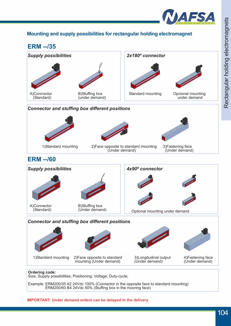
Mounting and supply possibilities for rectangular holding electromagnet
ERM --/35Supply possibilities
A)Connector (Standard)
B)Stuffing box(under demand)
2x180º connector
Standard mounting Opcional mounting under demand
1)Standard mounting 2)Face opposite to standard mounting (Under demand)
3)Fastening face (Under demand)
Connector and stuffing box different positions
ERM --/60Supply possibilities 4x90º connector
Connector and stuffing box different positions
A)Connector (Standard)
B)Stuffing box(Under demand) Optional mounting under demand
1)Standard mounting 2)Face opposite to standard mounting (Under demand)
4)Fastening face(Under demand)
3)Longitudinal output(Under demand)
IMPORTANT: Under demand orders can be delayed in the delivery
Ordering code:Size; Supply possibilities; Positioning; Voltage; Duty-cycle;
Example: ERM200/35 A2 24Vdc 100% (Connector in the opposite face to standard mounting) ERM200/60 B4 24Vdc 50% (Stuffing box in the mooring face)
105
www.nafsa.es
Rou
nd m
agne
tic h
oldi
ng e
lect
rom
agne
ts
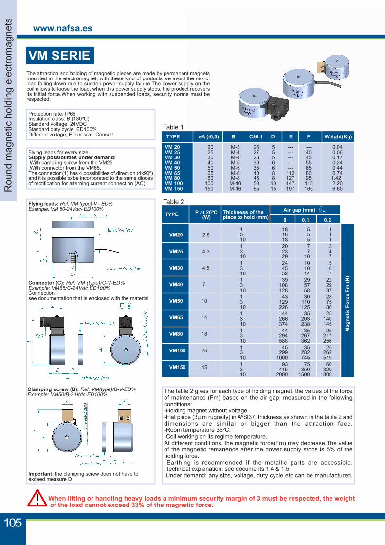
VM SERIEThe attraction and holding of magnetic pieces are made by permanent magnetsmounted in the electromagnet, with these kind of products we avoid the risk ofload falling down due to sudden power supply failure.The power supply on thecoil allows to loose the load, when this power supply stops, the product recoversits initial force.When working with suspended loads, security norms must berespected.
When lifting or handling heavy loads a minimum security margin of 3 must be respected, the weight of the load cannot exceed 33% of the magnetic force.
Protection rate: IP65Insulation class: B (130ºC)Standard voltage: 24VDCStandard duty cycle: ED100%Different voltage, ED or size: Consult
Flying leads for every sizeSupply possibilities under demand:.With campling screw from the VM25.With connector from the VM65.The connector (1) has 4 possibilities of direction (4x90º)and it is possible to be incorporated to the same diodesof rectification for alterning current connection (AC).
The table 2 gives for each type of holding magnet, the values of the forceof maintenance (Fm) based on the air gap, measured in the followingconditions:-Holding magnet without voltage.-Flat piece (3µ m rugosity) in AºSt37, thickness as shown in the table 2 anddimensions are similar or bigger than the attraction face.-Room temperature 35ºC.-Coil working on its regime temperature.At different conditions, the magnetic force(Fm) may decrease.The valueof the magnetic remanence after the power supply stops is 5% of theholding force.. Earthing is recommended if the metallic parts are accessible..Technical explanation: see documents 1.4 & 1.5.Under demand: any size, voltage, duty cycle etc can be manufactured.
Flying leads: Ref: VM (type)-V - ED%Example: VM 50-24Vdc- ED100%
Connector (C): Ref: VM (type)/C-V-ED%Example: VM65/C-24Vdc ED100%Connection:see documentation that is enclosed with the material
Clamping screw (B): Ref: VM(type)/B-V-ED%Example: VM50/B-24Vdc-ED100%
Table 2
1 18 5 13 18 5 110 18 5 11 20 7 33 23 7 410 29 10 71 24 10 53 45 10 610 52 14 71 39 29 223 108 57 2910 128 58 371 43 30 283 129 110 7510 226 125 801 44 35 253 266 203 14010 374 238 1451 44 35 253 294 267 21710 588 362 2561 45 35 253 299 282 26210 1000 745 5191 93 75 603 415 350 32010 2000 1500 1300
VM20 2.6
VM25 4.3
VM30 4.5
VM40 7
VM50 10
VM65 14
VM80 18
VM100 25
VM150 45
Mag
netic
For
ce F
m (N
)
TYPE P at 20ºC (W)
Thickness of thepiece to hold (mm)
Air gap (mm) dL
0 0.1 0.2
Table 1 TYPE øA (-0,3) B C±0.1 D E F Weight(Kg)
VM 20 20 M-3 25 5 --- --- 0.04 VM 25 25 M-4 27 5 --- 40 0.06 VM 30 30 M-4 28 5 --- 45 0.17 VM 40 40 M-5 30 6 --- 55 0.24 VM 50 50 M-5 35 6 --- 65 0.44 VM 65 65 M-8 40 8 112 80 0.74 VM 80 80 M-8 45 8 127 95 1.42 VM 100 100 M-10 50 10 147 115 2.20 VM 150 150 M-16 65 15 197 165 6.60
Important: the clamping screw does not have toexceed measure D
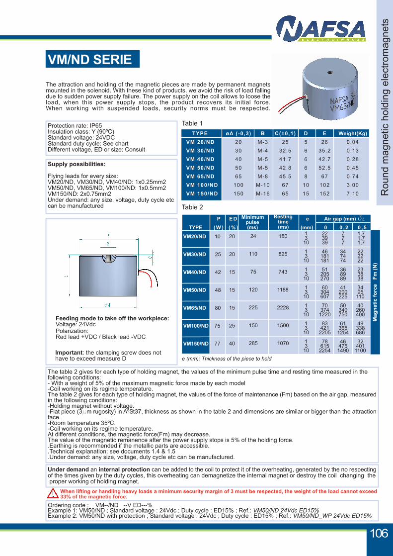
Table 2
VM/ND SERIE
Flying leads
Ordering code : VM--/ND --V ED---%Example 1: VM50/ND ; Standard voltage : 24Vdc ; Duty cycle : ED15% ; Ref.: VM50/ND 24Vdc ED15% Example 2: VM50/ND with protection ; Standard voltage : 24Vdc ; Duty cycle : ED15% ; Ref.: VM50/ND_WP 24Vdc ED15%
When lifting or handling heavy loads a minimum security margin of 3 must be respected, the weight of the load cannot exceed33% of the magnetic force.
Protection rate: IP65Insulation class: Y (90ºC)Standard voltage: 24VDCStandard duty cycle: See chartDifferent voltage, ED or size: Consult
Supply possibilities:
Flying leads for every size:VM20/ND, VM30/ND, VM40/ND: 1x0.25mm2VM50/ND, VM65/ND, VM100/ND: 1x0.5mm2VM150/ND: 2x0.75mm2Under demand: any size, voltage, duty cycle etccan be manufactured
The attraction and holding of the magnetic pieces are made by permanent magnetsmounted in the solenoid. With these kind of products, we avoid the risk of load fallingdue to sudden power supply failure. The power supply on the coil allows to loose theload, when this power supply stops, the product recovers its initial force.When working with suspended loads, security norms must be respected.
The table 2 gives for each type of holding magnet, the values of the minimum pulse time and resting time measured in thefollowing conditions:- With a weight of 5% of the maximum magnetic force made by each model-Coil working on its regime temperature.The table 2 gives for each type of holding magnet, the values of the force of maintenance (Fm) based on the air gap, measuredin the following conditions:-Holding magnet without voltage.-Flat piece (3mm rugosity) in AºSt37, thickness as shown in the table 2 and dimensions are similar or bigger than the attractionface.-Room temperature 35ºC.-Coil working on its regime temperature.At different conditions, the magnetic force(Fm) may decrease.The value of the magnetic remanence after the power supply stops is 5% of the holding force..Earthing is recommended if the metallic parts are accessible..Technical explanation: see documents 1.4 & 1.5.Under demand: any size, voltage, duty cycle etc can be manufactured.
Under demand an internal protection can be added to the coil to protect it of the overheating, generated by the no respectingof the times given by the duty cycles, this overheating can demagnetize the internal magnet or destroy the coil changing the proper working of holding magnet.
e (mm): Thickness of the piece to hold
P E D e Air gap (mm) dL
TYPE ( W ) ( % ) (mm) 0 0 , 2 0 , 5
Minimum pulse (ms)
Resting time (ms)
Rou
nd m
agne
tic h
oldi
ng e
lect
rom
agne
ts
106
Table 1 TYPE øA (-0,3) B C(±0,1) D E Weight(Kg)
VM 20/ND 20 M-3 25 5 26 0.04
VM 30/ND 30 M-4 32.5 6 35.2 0.13
VM 40/ND 40 M-5 41.7 6 42.7 0.28
VM 50/ND 50 M-5 42.8 6 52.5 0.45
VM 65/ND 65 M-8 45.5 8 67 0.74
VM 100/ND 100 M-10 67 10 102 3.00
VM 150/ND 150 M-16 65 15 152 7.10
Feeding mode to take off the workpiece:Voltage: 24VdcPolarization:Red lead +VDC / Black lead -VDC
Important: the clamping screw does nothave to exceed measure D
VM20/ND 10
VM30/ND 25
VM40/ND 42
VM50/ND 48
VM65/ND 80
VM100/ND 75
VM150/ND 77
20
20
15
15
15
25
40
24
110
75
120
225
150
285
180
825
743
1188
2228
1500
1070
1 3 10
1 3 10
1 3 10
1 3 10
1 3 10
1 3 10
1 3 10
22 39 39
46 181 181
51 205 270
60 304 607
70 3741220
83 4212205
78 6152254
7 7 7
34 74 74
36 89 89
41 200 225
50 340 750
61 3651254
46 4751490
1,7 1,7 1,7
22 22 22
23 38 38
34 95 110
40 260 400
49 338 686
32 4011100
Mag
netic
forc
e F
m (N
)
107
www.nafsa.es
Rec
tang
ular
mag
netic
hol
ding
ele
ctro
mag
nets
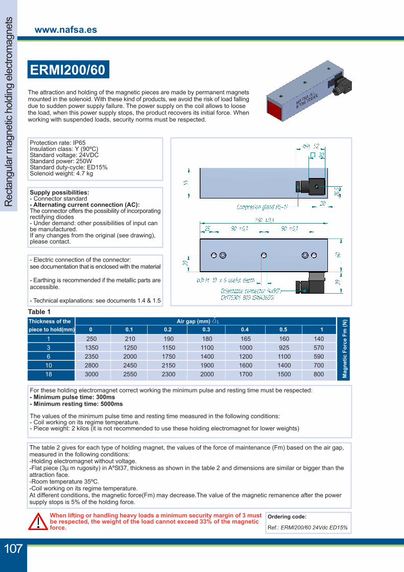
The attraction and holding of the magnetic pieces are made by permanent magnetsmounted in the solenoid. With these kind of products, we avoid the risk of load fallingdue to sudden power supply failure. The power supply on the coil allows to loosethe load, when this power supply stops, the product recovers its initial force. Whenworking with suspended loads, security norms must be respected.
When lifting or handling heavy loads a minimum security margin of 3 mustbe respected, the weight of the load cannot exceed 33% of the magneticforce.
Ordering code:
Ref.: ERMI200/60 24Vdc ED15%
The table 2 gives for each type of holding magnet, the values of the force of maintenance (Fm) based on the air gap,measured in the following conditions:-Holding electromagnet without voltage.-Flat piece (3µ m rugosity) in AºSt37, thickness as shown in the table 2 and dimensions are similar or bigger than theattraction face.-Room temperature 35ºC.-Coil working on its regime temperature.At different conditions, the magnetic force(Fm) may decrease.The value of the magnetic remanence after the powersupply stops is 5% of the holding force.
Protection rate: IP65Insulation class: Y (90ºC)Standard voltage: 24VDCStandard power: 250WStandard duty-cycle: ED15%Solenoid weight: 4.7 kg
Supply possibilities:- Connector standard- Alternating current connection (AC):The connector offers the possibility of incorporatingrectifying diodes- Under demand: other possibilities of input canbe manufactured.If any changes from the original (see drawing),please contact.
- Electric connection of the connector:see documentation that is enclosed with the material
- Earthing is recommended if the metallic parts areaccessible.
- Technical explanations: see documents 1.4 & 1.5
For these holding electromagnet correct working the minimum pulse and resting time must be respected:- Minimum pulse time: 300ms- Minimum resting time: 5000ms
The values of the minimum pulse time and resting time measured in the following conditions:- Coil working on its regime temperature.- Piece weight: 2 kilos (it is not recommended to use these holding electromagnet for lower weights)
ERMI200/60
Mag
netic
For
ce F
m (N
)
Table 1 Thickness of the Air gap (mm) dL
piece to hold(mm) 0 0.1 0.2 0.3 0.4 0.5 1
1 250 210 190 180 165 160 140 3 1350 1250 1150 1100 1000 925 570 6 2350 2000 1750 1400 1200 1100 590 10 2800 2450 2150 1900 1600 1400 700 18 3000 2550 2300 2000 1700 1500 800
N A F S A
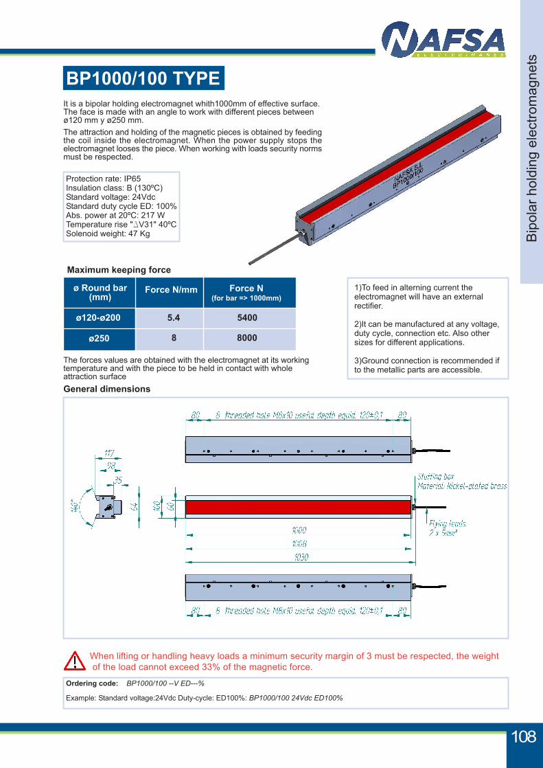
When lifting or handling heavy loads a minimum security margin of 3 must be respected, the weight of the load cannot exceed 33% of the magnetic force.
BP1000/100 TYPE
Ordering code: BP1000/100 --V ED---%
Example: Standard voltage:24Vdc Duty-cycle: ED100%: BP1000/100 24Vdc ED100%
Protection rate: IP65Insulation class: B (130ºC)Standard voltage: 24VdcStandard duty cycle ED: 100%Abs. power at 20ºC: 217 WTemperature rise "DV31" 40ºCSolenoid weight: 47 Kg
1)To feed in alterning current theelectromagnet will have an externalrectifier.
2)It can be manufactured at any voltage,duty cycle, connection etc. Also othersizes for different applications.
3)Ground connection is recommended ifto the metallic parts are accessible.
General dimensions
Bip
olar
hol
ding
ele
ctro
mag
nets
108
It is a bipolar holding electromagnet whith1000mm of effective surface.The face is made with an angle to work with different pieces betweenø120 mm y ø250 mm.The attraction and holding of the magnetic pieces is obtained by feedingthe coil inside the electromagnet. When the power supply stops theelectromagnet looses the piece. When working with loads security normsmust be respected.
The forces values are obtained with the electromagnet at its workingtemperature and with the piece to be held in contact with wholeattraction surface
ø120-ø200
ø250
ø Round bar(mm)
Force N/mm
5.4
8
Maximum keeping force
Force N(for bar => 1000mm)
5400
8000